EP2698244A1 - Sleeveless tire building drum with interchangeable width elements - Google Patents
Sleeveless tire building drum with interchangeable width elements Download PDFInfo
- Publication number
- EP2698244A1 EP2698244A1 EP13180170.6A EP13180170A EP2698244A1 EP 2698244 A1 EP2698244 A1 EP 2698244A1 EP 13180170 A EP13180170 A EP 13180170A EP 2698244 A1 EP2698244 A1 EP 2698244A1
- Authority
- EP
- European Patent Office
- Prior art keywords
- tire building
- center section
- center
- building drum
- drum
- Prior art date
- Legal status (The legal status is an assumption and is not a legal conclusion. Google has not performed a legal analysis and makes no representation as to the accuracy of the status listed.)
- Granted
Links
Images


Classifications
-
- B—PERFORMING OPERATIONS; TRANSPORTING
- B29—WORKING OF PLASTICS; WORKING OF SUBSTANCES IN A PLASTIC STATE IN GENERAL
- B29D—PRODUCING PARTICULAR ARTICLES FROM PLASTICS OR FROM SUBSTANCES IN A PLASTIC STATE
- B29D30/00—Producing pneumatic or solid tyres or parts thereof
- B29D30/06—Pneumatic tyres or parts thereof (e.g. produced by casting, moulding, compression moulding, injection moulding, centrifugal casting)
- B29D30/08—Building tyres
- B29D30/20—Building tyres by the flat-tyre method, i.e. building on cylindrical drums
- B29D30/24—Drums
- B29D30/244—Drums for manufacturing substantially cylindrical tyre components with cores or beads, e.g. carcasses
- B29D30/245—Drums for the single stage building process, i.e. the building-up of the cylindrical carcass and the toroidal expansion of it are realised on the same drum
-
- B—PERFORMING OPERATIONS; TRANSPORTING
- B29—WORKING OF PLASTICS; WORKING OF SUBSTANCES IN A PLASTIC STATE IN GENERAL
- B29D—PRODUCING PARTICULAR ARTICLES FROM PLASTICS OR FROM SUBSTANCES IN A PLASTIC STATE
- B29D30/00—Producing pneumatic or solid tyres or parts thereof
- B29D30/06—Pneumatic tyres or parts thereof (e.g. produced by casting, moulding, compression moulding, injection moulding, centrifugal casting)
- B29D30/08—Building tyres
- B29D30/20—Building tyres by the flat-tyre method, i.e. building on cylindrical drums
- B29D30/24—Drums
- B29D30/26—Accessories or details, e.g. membranes, transfer rings
Definitions
- the invention relates to a tire building drum, more particularly to a tire building drum with no center sleeve.
- the manufacture of tires typically involves a tire building drum wherein numerous tire components are applied to the drum in sequence, forming a cylindrical shaped tire carcass. This stage of the tire building process is commonly referred to as the "first stage" of the tire building process.
- the tire carcass is then typically removed from the tire building drum and sent to a second stage, expandable tire shaping drum where the carcass is expanded into a toroidal shape for receipt of the remaining components of the tire such as the belt package and a rubber tread.
- the completed toroidally shape unvulcanized tire carcass or green tire is then removed from the second stage drum and subsequently molded and vulcanized into a finished tire.
- the prior art process thus requires two tire building drums and the transfer of the carcass from one drum to the other. Further, a problem often arises in precisely locating and anchoring the tire beads on the unvulcanized tire carcass, especially during the transportation of the tire beads from the first stage drum to the second stage drum. Variations in bead positioning can result in ply distortion in the tire.
- Tire manufacturers have recently begun moving towards the utilization of a single tire building drum, for both the first and second stage tire building. This requires that the tire building drum be capable of axial expansion and contraction as well as radial expansion/contraction. Further, it is important to maintain a positive bead lock during the entire tire building process, including the tire shaping, so that the ply cord length is maintained, resulting in good tire uniformity.
- Tire manufacturers typically use a flexible cylindrical rubberized center sleeve as the outermost element on tire building drums.
- the center sleeve functions as the surface of application and point of fixation for the innermost component of the tire (innerliner).
- the section where the center sleeve wraps around the "shoulder" of the radially expansible segments also serves as a pneumatic seal against the bead area of the green tire, enabling inflation (shaping) of the green tire in the full-stage tire building process.
- the center sleeve also typically has a series of holes for providing a vacuum to secure the innerliner to the drum and the air to shape the green tire.
- the tire building drums typically have a wide range of width adjustability, while the prior art rubber center sleeves have a very limited range of width operation, typically less than 30 mm.
- the sleeve limits the action of the tire building drum, resulting in the need to change out the drum with another drum having a different width centersleeve in place.
- the necessity of changing out of the drum requires the storage of drums for different width sizes, and the loss in productivity during the drum change outs.
- a second disadvantage to the prior art center sleeves is that during the tire building cycle the drum width is progressively reduced as the shaped diameter of the green tire increases. This reduced width action may result in the bunching up or buckling of the sleeve due to compression. As the buckled diameter is larger than the bead diameter of the tire, it is necessary to widen the width of the tire building drum in order to remove the finished tire from the drum.
- a third disadvantage to the prior art center sleeves is that they are the highest maintenance component on the tire building drum, requiring frequent replacement when they become torn or blistered.
- a fourth disadvantage to the prior art center sleeves is that the use of the sleeve results in an increased amount of force required to expand the drum.
- a fifth disadvantage to the prior art center sleeves is that the use of the sleeve can result in uneven air flow distribution during inflation of the carcass, contributing to tire nonuniformity.
- Axial and “axially” means the lines or directions that are parallel or aligned with the longitudinal axis of rotation of the tire building drum.
- “Circumferential” means lines or directions extending along the perimeter of the surface of the annular tread perpendicular to the axial direction.
- Ring and radially mean directions radially toward or away from the axis of rotation of the tire building drum.
- the tire building drum 5 has a left hand side 7 and a right hand side 9 joined together by a center section 20.
- the center section 20 is further divided into a right hand side 22b and a left hand side 22a, which are both axially and radially movable, as described in more detail, below.
- Adjacent the center section 20 are first and second bead locking mechanisms 25a, 25b, which are also radially movable as shown in Figure 2 .
- Adjacent the bead locking mechanisms are first and second shoulder sections 29. Both the bead locking mechanisms and the shoulder sections are axially movable and are driven by the center screw mechanism 121.
- both the left hand side and the right hand side of the drum are axially movable.
- the center section 20 of the tire building drum further comprises a plurality of center segments 22a, 22b located about the outer circumference of the drum.
- Each of the center segments may be further split into a left hand side 22a and a right hand side 22b, although not required.
- the left hand side center segment 22a has one or more finger like projections or rods 24a, with recesses 26a located between the finger projections.
- the rods 24a slide in recesses 26b formed between fingers 24b.
- the right hand side is the mirror opposite.
- the right hand side center segments 22b has one or more finger like projections or rods 24b that slide in recess 26a which are located between fingers 24a.
- Each of the finger like projections or rods 24a are received in a respective recess 42a, 42b of mounting block 40a, 40b.
- the center section left hand side and the right hand side interdigitate or interlock like fingers of a folding hands in order to actuate the center section of the drum 20.
- a right hand center segment 22b is illustrated.
- the right hand center segment is shown having three finger like projections shaped like a rod 24b.
- Each rod 24b is received in recesses 42b of a mounting block 40b.
- the finger like projections 24b are secured within recess 42b of mounting block 40b via clamp 44b.
- a plurality of the mounting blocks 40a, 40b are arranged on opposite ends in an annular arrangement.
- the mounting blocks together with the finger like rods form the outer radial surface of the drum.
- the segments have been redesigned so that the innerliner is applied directly to the outer radial surface of the finger like rods instead of the center sleeve.
- At least one finger of a segment is equipped with holes 80 connected to a vacuum source to enable fixing the leading edge of the innerliner to the drum using vacuum.
- a finger of each of a left segment and a right segment is equipped with the holes 80.
- the holes 80 may also be used to port air to inflate the tire into a toroid.
- the radial height H of the mounting block may be increased or decreased as desired.
- the finger like projections having the same dimensions may be used interchangeably with mounting blocks of different radial dimensions in order to form drums of varying diameters. The interchangeability of the finger like projections reduce the amount of parts required to be kept in stock.
- left hand center segment 22a has three finger-like projections 24a which are slidably received in three elongate slots 26b formed between fingers 24b in an interdigitated or interlocked manner.
- right hand center segment 22b has three finger like projections 24b which are slidably received in three opposed elongate slots 26a located between fingers 24a.
- the center segments 22a, 22b thus cooperate with each other to axially expand or contract as the fingers slide within the recesses.
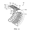
- Figure 4 shows the center section in the collapsed position.
- Figure 2 illustrates the center section 20 in the radially expanded position.
- the center section 20 can radially expand in the range of 20 to 50 mm for instance. As each center segment 22a, 22b radially expands, the gap between the fingers of the center segments increases.
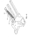
- Figure 7 further illustrates an optional feature of the tire building drum.
- Figure 9 illustrates a resilient splice plate 100.
- the splice plate has a flat surface for performing a splice.
- the first end 102 of the splice plate is hinged.
- the second end 104 of the splice plate is connected to a spring 106.
- the second end 104 of the splice plate may be in engagement with a stationary splice plate 110 located on the second half of the center section as shown in Figure 9 .
- the stationary splice plate 110 supports the resilient splice plate 100.
- the tire building drum 5 of the present invention does not have a center sleeve, nor a sleeve or any type of rubber component that extends from one end of the center section to the other end, nor a sleeve that is located in the center of the center section of the drum.
- the tire building drum of the present invention has eliminated the center sleeve, and includes a first and second shoulder seal 60a, 60b.
- the purpose of the shoulder seals is to maintain the pneumatic seal between the bead of the green tire and the tire building drum, enabling inflation and shaping of the green tire in the full stage tire building process.
- the first and second shoulder seal 60a, 60b are located on the axially outer ends of the segments 22a, 22b forming the center section.
- Each center seal preferably has an overall annular shape, having a first end 62a, 62b which is secured in seal clamps (not shown) located adjacent the center section segments.
- the first ends 62a, 62b of the seal have an outer bead projection 63 for mating reception with inner protrusion of the seal clamp.
- the shoulder seals each further comprise a second end 64a, 64b that is a free or unconstrained end.
- the free end 64a, 64b rests on the outer surface 23a, 23b ( Fig. 6 ) of the center segments 22a, 23b, and will slide relative to the center segments when the drum is radially expanded.
- the outer surface 23a, 23b has a smaller outer diameter than the center of the center section, forming a radial step so that when the shoulder seals are mounted, the shoulder seals form a flush surface with the center section of the drum.
- the shoulder seal is preferably molded into an L shape as shown in Figure 4 .
- the shoulder seal may be made of rubber or polyurethane or other flexible polymers.
- first and second annular bead locking mechanisms 25 Adjacent the center section 20 are first and second annular bead locking mechanisms 25.
- Figure 2 illustrates the bead locking mechanisms 25 in the retracted position.
- the right and left hand shoulder section 29 of the tire building drum 5 is defined as the drum components located axially outward of the centerline of the center section, inclusive of the seal clamps and the bead lock mechanisms.
- the left and right hand shoulder sections of the tire building drum are axially slidable on bearing sleeves.
- the shoulder sections 29 are actuated by drive pins 125 mounted on nuts 130, which ride along drive screw 121. When the central screw is rotated, the nuts 130 move axially inward/outward, causing the drive pins 125 and each shoulder section to move axially inward/outward in corresponding fashion.
- the drive pins are also in mechanical cooperation with the split center segments, causing the split center segments 22a, 22b to axially extend or contract.
- a central drive shaft is provided for rotational movement of the tire building drum 5 about its longitudinal axis.
- the central shaft is connected to a drive means (not shown).
- a central screw 121 Provided within the central drive shaft is a central screw 121.
- the central screw 121 is supported at each end by bearings.
- the threads on one side of the central screw 121 are left handed and on the opposite side are right handed.
- On the left hand side is an inboard nut connected to the one end of the threaded screw 121 and similarly on the opposite right hand side is an outboard ball nut connected to the central screw 121.
- An upper bladder extends axially outward from the bead lock mechanism 25 to the respective ends of the tire building drum.
- the upper bladder extends over a lower bladder, which is mounted in the shoulder area of the drum and extends axially outward to the respective ends of the tire building drum.
- the upper and lower bladders function as turnup bladders which are used to inflate and, thereby, make the turn-up ends of the ply wrap about the apex and bead cores.
Abstract
Description
- The invention relates to a tire building drum, more particularly to a tire building drum with no center sleeve.
- The manufacture of tires typically involves a tire building drum wherein numerous tire components are applied to the drum in sequence, forming a cylindrical shaped tire carcass. This stage of the tire building process is commonly referred to as the "first stage" of the tire building process. The tire carcass is then typically removed from the tire building drum and sent to a second stage, expandable tire shaping drum where the carcass is expanded into a toroidal shape for receipt of the remaining components of the tire such as the belt package and a rubber tread. The completed toroidally shape unvulcanized tire carcass or green tire is then removed from the second stage drum and subsequently molded and vulcanized into a finished tire.
- The prior art process thus requires two tire building drums and the transfer of the carcass from one drum to the other. Further, a problem often arises in precisely locating and anchoring the tire beads on the unvulcanized tire carcass, especially during the transportation of the tire beads from the first stage drum to the second stage drum. Variations in bead positioning can result in ply distortion in the tire.
- Tire manufacturers have recently begun moving towards the utilization of a single tire building drum, for both the first and second stage tire building. This requires that the tire building drum be capable of axial expansion and contraction as well as radial expansion/contraction. Further, it is important to maintain a positive bead lock during the entire tire building process, including the tire shaping, so that the ply cord length is maintained, resulting in good tire uniformity.
- Tire manufacturers typically use a flexible cylindrical rubberized center sleeve as the outermost element on tire building drums. The center sleeve functions as the surface of application and point of fixation for the innermost component of the tire (innerliner). The section where the center sleeve wraps around the "shoulder" of the radially expansible segments also serves as a pneumatic seal against the bead area of the green tire, enabling inflation (shaping) of the green tire in the full-stage tire building process. The center sleeve also typically has a series of holes for providing a vacuum to secure the innerliner to the drum and the air to shape the green tire.
- There are several disadvantages to the prior art rubber center sleeves. The tire building drums typically have a wide range of width adjustability, while the prior art rubber center sleeves have a very limited range of width operation, typically less than 30 mm. Thus the sleeve limits the action of the tire building drum, resulting in the need to change out the drum with another drum having a different width centersleeve in place. The necessity of changing out of the drum requires the storage of drums for different width sizes, and the loss in productivity during the drum change outs.
- A second disadvantage to the prior art center sleeves is that during the tire building cycle the drum width is progressively reduced as the shaped diameter of the green tire increases. This reduced width action may result in the bunching up or buckling of the sleeve due to compression. As the buckled diameter is larger than the bead diameter of the tire, it is necessary to widen the width of the tire building drum in order to remove the finished tire from the drum.
- A third disadvantage to the prior art center sleeves is that they are the highest maintenance component on the tire building drum, requiring frequent replacement when they become torn or blistered.
- A fourth disadvantage to the prior art center sleeves is that the use of the sleeve results in an increased amount of force required to expand the drum.
- A fifth disadvantage to the prior art center sleeves is that the use of the sleeve can result in uneven air flow distribution during inflation of the carcass, contributing to tire nonuniformity.
- Thus it is desired to provide a tire building drum that overcomes the above described disadvantages.
- "Axial" and "axially" means the lines or directions that are parallel or aligned with the longitudinal axis of rotation of the tire building drum.
- "Circumferential" means lines or directions extending along the perimeter of the surface of the annular tread perpendicular to the axial direction.
- "Radial" and "radially" mean directions radially toward or away from the axis of rotation of the tire building drum.
- The invention will be described by way of example and with reference to the accompanying drawings in which:
-
Figure 1A is a perspective view of a tire building drum of the present invention shown having two shoulder sleeves mounted on the crown portion of the drum; -
Figure 1B is a perspective view of the tire building drum ofFigure 1a shown with the outer covering of the left and right hand side of the drums removed. -
Figure 2 is a front cross-sectional view of the tire building drum ofFigure 1 shown in the radially expanded position; -
Figure 3 is a close-up view of the center section of the tire building drum ofFigure 1 ; -
Figure 4 is a perspective view of the center section only shown in the radially expanded position; -
Figure 5 is a perspective view of a single center section segment; -
Figure 6 is a bottom view of the single center section segment ofFig. 8 ; -
Figure 7 is a perspective view of a single center section segment having a splice plate; -
Figure 8 is a bottom view of the single center section segment ofFig. 7 illustrating the bottom spring; and -
Figure 9 is close up view of a portion of the center section showing the splice bar. - With reference to the Figures, an exemplary
tire building drum 5 of the present invention is illustrated. As shown more particularly inFigures 1A and1B , thetire building drum 5 has aleft hand side 7 and aright hand side 9 joined together by acenter section 20. Thecenter section 20 is further divided into aright hand side 22b and aleft hand side 22a, which are both axially and radially movable, as described in more detail, below. Adjacent thecenter section 20 are first and secondbead locking mechanisms Figure 2 . Adjacent the bead locking mechanisms are first andsecond shoulder sections 29. Both the bead locking mechanisms and the shoulder sections are axially movable and are driven by thecenter screw mechanism 121. Thus, both the left hand side and the right hand side of the drum are axially movable. These components are described in more detail, below. - The
center section 20 of the tire building drum, as shown inFigures 1-5 , further comprises a plurality ofcenter segments left hand side 22a and aright hand side 22b, although not required. As shown inFigure 3 , the left handside center segment 22a has one or more finger like projections orrods 24a, withrecesses 26a located between the finger projections. Therods 24a slide inrecesses 26b formed betweenfingers 24b. The right hand side is the mirror opposite. Thus the right handside center segments 22b has one or more finger like projections orrods 24b that slide inrecess 26a which are located betweenfingers 24a. Each of the finger like projections orrods 24a are received in arespective recess 42a, 42b ofmounting block drum 20. - As shown in
Figure 5 , a righthand center segment 22b is illustrated. The right hand center segment is shown having three finger like projections shaped like arod 24b. Eachrod 24b is received inrecesses 42b of amounting block 40b. The finger likeprojections 24b are secured withinrecess 42b of mountingblock 40b viaclamp 44b. A plurality of the mountingblocks Figure 7 ) is equipped withholes 80 connected to a vacuum source to enable fixing the leading edge of the innerliner to the drum using vacuum. Preferably, a finger of each of a left segment and a right segment is equipped with theholes 80. Theholes 80 may also be used to port air to inflate the tire into a toroid. - In order to have different size center sections, the radial height H of the mounting block may be increased or decreased as desired. The finger like projections having the same dimensions may be used interchangeably with mounting blocks of different radial dimensions in order to form drums of varying diameters. The interchangeability of the finger like projections reduce the amount of parts required to be kept in stock.
- As shown in
Figure 3 , lefthand center segment 22a has three finger-like projections 24a which are slidably received in threeelongate slots 26b formed betweenfingers 24b in an interdigitated or interlocked manner. Likewise, righthand center segment 22b has three finger likeprojections 24b which are slidably received in three opposedelongate slots 26a located betweenfingers 24a. Thecenter segments -
Figure 4 shows the center section in the collapsed position.Figure 2 illustrates thecenter section 20 in the radially expanded position. Thecenter section 20 can radially expand in the range of 20 to 50 mm for instance. As eachcenter segment -
Figure 7 further illustrates an optional feature of the tire building drum.
Figure 9 illustrates aresilient splice plate 100. The splice plate has a flat surface for performing a splice. Thefirst end 102 of the splice plate is hinged. Thesecond end 104 of the splice plate is connected to aspring 106. Thesecond end 104 of the splice plate may be in engagement with astationary splice plate 110 located on the second half of the center section as shown inFigure 9 . Thestationary splice plate 110 supports theresilient splice plate 100. - The
tire building drum 5 of the present invention does not have a center sleeve, nor a sleeve or any type of rubber component that extends from one end of the center section to the other end, nor a sleeve that is located in the center of the center section of the drum. The tire building drum of the present invention has eliminated the center sleeve, and includes a first andsecond shoulder seal second shoulder seal segments first end second end free end outer surface 23a, 23b (Fig. 6 ) of thecenter segments outer surface 23a, 23b has a smaller outer diameter than the center of the center section, forming a radial step so that when the shoulder seals are mounted, the shoulder seals form a flush surface with the center section of the drum. - The shoulder seal is preferably molded into an L shape as shown in
Figure 4 . The shoulder seal may be made of rubber or polyurethane or other flexible polymers. - Adjacent the
center section 20 are first and second annular bead locking mechanisms 25.Figure 2 illustrates the bead locking mechanisms 25 in the retracted position. - The right and left
hand shoulder section 29 of thetire building drum 5 is defined as the drum components located axially outward of the centerline of the center section, inclusive of the seal clamps and the bead lock mechanisms. The left and right hand shoulder sections of the tire building drum are axially slidable on bearing sleeves. Theshoulder sections 29 are actuated bydrive pins 125 mounted onnuts 130, which ride alongdrive screw 121. When the central screw is rotated, thenuts 130 move axially inward/outward, causing the drive pins 125 and each shoulder section to move axially inward/outward in corresponding fashion. In addition, the drive pins are also in mechanical cooperation with the split center segments, causing thesplit center segments - A central drive shaft is provided for rotational movement of the
tire building drum 5 about its longitudinal axis. The central shaft is connected to a drive means (not shown). Provided within the central drive shaft is acentral screw 121. Thecentral screw 121 is supported at each end by bearings. The threads on one side of thecentral screw 121 are left handed and on the opposite side are right handed. On the left hand side is an inboard nut connected to the one end of the threadedscrew 121 and similarly on the opposite right hand side is an outboard ball nut connected to thecentral screw 121. - An upper bladder extends axially outward from the bead lock mechanism 25 to the respective ends of the tire building drum. The upper bladder extends over a lower bladder, which is mounted in the shoulder area of the drum and extends axially outward to the respective ends of the tire building drum. The upper and lower bladders function as turnup bladders which are used to inflate and, thereby, make the turn-up ends of the ply wrap about the apex and bead cores.
Claims (7)
- A tire building drum comprising: a rotatable drum having a center section (20) and a first and second shoulder section (29), said center section (20) being radially expandable, wherein said center section has no center sleeve, wherein said center section has a first and second end (62a, 62b), wherein the first and second end (62a, 62b) each have a shoulder, wherein the center section (20) further comprises a first and second shoulder seal (60a, 60b) having a first end received in a clamp (44b) and a second free end slidable on the first and second end of the center section (20) so that the shoulder seal extends over the shoulder of the center section (20).
- The tire building drum of claim 1 wherein said center section has segments comprising a first half and a second half, wherein the first half is slidably mounted within the second half.
- The tire building drum of claim 2 wherein the first half and the second half are each formed from one or more mounting blocks (40a, 40b), wherein each mounting block (40a, 40b) has a recess (42a, 42B) for receiving one or more rods (24a, 24b).
- The tire building drum of claim 3 wherein the rods (24a, 24b) are removably secured to the mounting blocks (40a, 40b).
- The tire building drum of claim 3 or 4 wherein each mounting block (40a, 40b) has at least three rods separated by a recess, wherein the rods of the first half are aligned for reception into recesses of the second half.
- The tire building drum of claim 3, 4 or 5 wherein at least one rod has a plurality of holes (80).
- The tire building drum of at least one of the claims 3 to 6 wherein the mounting blocks have a radial height and are interchangeable with mounting blocks having a different radial height.
Applications Claiming Priority (2)
| Application Number | Priority Date | Filing Date | Title |
|---|---|---|---|
| US201261683242P | 2012-08-15 | 2012-08-15 | |
| US13/774,118 US20140048213A1 (en) | 2012-08-15 | 2013-02-22 | Sleeveless tire building drum with interchangeable width elements |
Publications (2)
| Publication Number | Publication Date |
|---|---|
| EP2698244A1 true EP2698244A1 (en) | 2014-02-19 |
| EP2698244B1 EP2698244B1 (en) | 2015-03-18 |
Family
ID=49000785
Family Applications (1)
| Application Number | Title | Priority Date | Filing Date |
|---|---|---|---|
| EP13180170.6A Not-in-force EP2698244B1 (en) | 2012-08-15 | 2013-08-13 | Sleeveless tire building drum with interchangeable width elements |
Country Status (4)
| Country | Link |
|---|---|
| US (1) | US20140048213A1 (en) |
| EP (1) | EP2698244B1 (en) |
| JP (1) | JP6250328B2 (en) |
| CN (1) | CN103660336B (en) |
Cited By (2)
| Publication number | Priority date | Publication date | Assignee | Title |
|---|---|---|---|---|
| EP3037249A1 (en) * | 2014-12-23 | 2016-06-29 | The Goodyear Tire & Rubber Company | Sleeveless tire building drum |
| WO2020080934A1 (en) * | 2018-10-19 | 2020-04-23 | Vmi Holland B.V. | Tire building drum and method for tire building |
Families Citing this family (5)
| Publication number | Priority date | Publication date | Assignee | Title |
|---|---|---|---|---|
| WO2016099474A1 (en) * | 2014-12-17 | 2016-06-23 | Compagnie Generale Des Etablissements Michelin | Method and apparatus for molding non-pneumatic wheels |
| WO2016099476A1 (en) * | 2014-12-17 | 2016-06-23 | Compagnie Generale Des Etablissements Michelin | Method and apparatus for molding non-pneumatic wheels |
| CN107953582B (en) * | 2017-11-30 | 2020-04-21 | 正新橡胶(中国)有限公司 | Tyre forming and jointing drum |
| CN109501346A (en) * | 2018-12-30 | 2019-03-22 | 萨驰华辰机械(苏州)有限公司 | A kind of assembly drum and tyre building machine |
| JP2023523042A (en) * | 2020-04-22 | 2023-06-01 | エー. ジョーンズ,ウィリアム | Shoulder assembly for tire building machine |
Citations (6)
| Publication number | Priority date | Publication date | Assignee | Title |
|---|---|---|---|---|
| US3207648A (en) * | 1962-02-01 | 1965-09-21 | Akron Standard Mold Co | Tire building apparatus |
| DE1579183B1 (en) * | 1966-05-03 | 1970-05-27 | Continental Gummi Werke Ag | Tire building drum |
| US4855008A (en) * | 1988-05-09 | 1989-08-08 | The Goodyear Tire & Rubber Company | Expandable tire building drum |
| US6012500A (en) * | 1998-01-23 | 2000-01-11 | Bridgestone/Firestone, Inc. | Second stage tire building machine utilizing bladderless former sleeve |
| EP2072240A1 (en) * | 2007-12-18 | 2009-06-24 | The Goodyear Tire & Rubber Company | Sleeveless tire building drum |
| WO2010103393A1 (en) * | 2009-03-13 | 2010-09-16 | Marangoni Meccanica S.P.A. | Tire carcass building method and drum |
Family Cites Families (23)
| Publication number | Priority date | Publication date | Assignee | Title |
|---|---|---|---|---|
| GB1113622A (en) * | 1964-09-08 | 1968-05-15 | Dunlop Co Ltd | Improvements in or relating to apparatus for the manufacture of pneumatic tyres |
| US3616059A (en) * | 1968-06-12 | 1971-10-26 | Nat Standard Co | Apparatus for encasing beads into a tire |
| DE2317655A1 (en) * | 1973-04-07 | 1974-10-24 | Continental Gummi Werke Ag | Tyre blank inflation without internal bag - by sealing tyre sides with plates having edge seals |
| US4148682A (en) * | 1977-07-05 | 1979-04-10 | Eaton Corporation | Fluid expandable tire building drum |
| US4214939A (en) * | 1978-03-15 | 1980-07-29 | Nrm Corporation | Tire building machine |
| US4214941A (en) * | 1978-10-02 | 1980-07-29 | The B. F. Goodrich Company | Tire drum support |
| US4210482A (en) * | 1978-10-25 | 1980-07-01 | Eaton Corporation | Variable width tire building drum |
| US4229246A (en) * | 1978-12-18 | 1980-10-21 | The Steelastic Company | Building drum assembly |
| JPS57205132A (en) * | 1981-06-12 | 1982-12-16 | Mitsubishi Heavy Ind Ltd | Bead locking device of tire forming drum |
| US4929298A (en) * | 1988-05-13 | 1990-05-29 | The Goodyear Tire & Rubber Company | Tire building drum including an expandable segmental cylinder assembly and a vacuum chamber |
| JPH0319831A (en) * | 1989-06-16 | 1991-01-29 | Sumitomo Rubber Ind Ltd | Tyre molding method and molding drum therefor |
| US5066354A (en) * | 1990-05-25 | 1991-11-19 | Cooper Tire And Rubber Company | Building drum for a tire belt-tread stock package |
| IT1303143B1 (en) * | 1998-07-10 | 2000-10-30 | Bridgestone Firestone Tech | UNISTAGE DRUM FOR TIRE FORMING |
| IT1320456B1 (en) * | 2000-06-27 | 2003-11-26 | Bridgestone Firestone Tech | DRUM FOR TIRE FORMING. |
| US6769468B2 (en) * | 2001-09-21 | 2004-08-03 | The Goodyear Tire & Rubber Company | Tire building drum having expandable center section and independently expandable bead lock assemblies in the end sections |
| US6827119B2 (en) * | 2002-03-11 | 2004-12-07 | The Goodyear Tire & Rubber Company | Radially expansible tire assembly drum and method for forming tires |
| DE602004009411T2 (en) * | 2003-02-07 | 2008-07-24 | Bridgestone Corp. | METHOD AND DEVICE FOR RETRACTING TIRE STRUCTURAL MEMBERS |
| US20050028920A1 (en) * | 2003-08-04 | 2005-02-10 | Roedseth John Kolbjoern | High crown first stage tire building drum |
| US7287568B2 (en) * | 2004-12-23 | 2007-10-30 | The Goodyear Tire & Rubber Company | High crown uni-stage tire building drum |
| JP4962833B2 (en) * | 2005-11-30 | 2012-06-27 | 横浜ゴム株式会社 | Molding drum |
| ITTO20060118A1 (en) * | 2006-02-21 | 2007-08-22 | Bridgestone Corp | TIRE DRYING DRUM |
| US20100101732A1 (en) * | 2008-10-23 | 2010-04-29 | Howley Sean E | Method and apparatus for establishing obtainable range of diameters of a working drum |
| US10259181B2 (en) * | 2012-08-15 | 2019-04-16 | The Goodyear Tire & Rubber Company | Sleeveless tire building drum |
-
2013
- 2013-02-22 US US13/774,118 patent/US20140048213A1/en not_active Abandoned
- 2013-08-13 EP EP13180170.6A patent/EP2698244B1/en not_active Not-in-force
- 2013-08-15 JP JP2013168796A patent/JP6250328B2/en active Active
- 2013-08-15 CN CN201310355012.1A patent/CN103660336B/en not_active Expired - Fee Related
Patent Citations (6)
| Publication number | Priority date | Publication date | Assignee | Title |
|---|---|---|---|---|
| US3207648A (en) * | 1962-02-01 | 1965-09-21 | Akron Standard Mold Co | Tire building apparatus |
| DE1579183B1 (en) * | 1966-05-03 | 1970-05-27 | Continental Gummi Werke Ag | Tire building drum |
| US4855008A (en) * | 1988-05-09 | 1989-08-08 | The Goodyear Tire & Rubber Company | Expandable tire building drum |
| US6012500A (en) * | 1998-01-23 | 2000-01-11 | Bridgestone/Firestone, Inc. | Second stage tire building machine utilizing bladderless former sleeve |
| EP2072240A1 (en) * | 2007-12-18 | 2009-06-24 | The Goodyear Tire & Rubber Company | Sleeveless tire building drum |
| WO2010103393A1 (en) * | 2009-03-13 | 2010-09-16 | Marangoni Meccanica S.P.A. | Tire carcass building method and drum |
Cited By (4)
| Publication number | Priority date | Publication date | Assignee | Title |
|---|---|---|---|---|
| EP3037249A1 (en) * | 2014-12-23 | 2016-06-29 | The Goodyear Tire & Rubber Company | Sleeveless tire building drum |
| WO2020080934A1 (en) * | 2018-10-19 | 2020-04-23 | Vmi Holland B.V. | Tire building drum and method for tire building |
| NL2021842B1 (en) * | 2018-10-19 | 2020-05-13 | Vmi Holland Bv | Tire building drum and method for tire building |
| US11312096B2 (en) | 2018-10-19 | 2022-04-26 | Vmi Holland B.V. | Tire building drum and method for tire building |
Also Published As
| Publication number | Publication date |
|---|---|
| CN103660336A (en) | 2014-03-26 |
| JP2014037140A (en) | 2014-02-27 |
| EP2698244B1 (en) | 2015-03-18 |
| US20140048213A1 (en) | 2014-02-20 |
| JP6250328B2 (en) | 2017-12-20 |
| CN103660336B (en) | 2016-08-17 |
Similar Documents
| Publication | Publication Date | Title |
|---|---|---|
| EP3037249B1 (en) | Sleeveless tire building drum | |
| EP2698244B1 (en) | Sleeveless tire building drum with interchangeable width elements | |
| EP2698243B1 (en) | Sleeveless tire building drum | |
| EP2868463B1 (en) | Tire building drum | |
| JP4943702B2 (en) | High crown single stage tire building drum | |
| EP1295704B1 (en) | Tire building drum | |
| US6769468B2 (en) | Tire building drum having expandable center section and independently expandable bead lock assemblies in the end sections | |
| KR101929054B1 (en) | Solid deck bead lock drum | |
| US7288160B2 (en) | Method of making a tire using a high crown uni-stage tire building drum | |
| US3698987A (en) | Tire building drum | |
| US11001022B2 (en) | Method for manufacturing motorcycle tire | |
| JP4516338B2 (en) | Method and apparatus for assembling a tread belt | |
| CN109421302B (en) | Method of building a tyre | |
| CN109421298B (en) | Method of building a tyre | |
| US20100269976A1 (en) | Process and plant for building tyres for vehicle wheels | |
| CN113002035B (en) | Tire building drum and method of building a tire | |
| JP2009160850A (en) | Tire molding apparatus | |
| JP2006224521A (en) | Tire molding machine | |
| JP2022047318A (en) | Molding method of band-like member |
Legal Events
| Date | Code | Title | Description |
|---|---|---|---|
| AK | Designated contracting states |
Kind code of ref document: A1 Designated state(s): AL AT BE BG CH CY CZ DE DK EE ES FI FR GB GR HR HU IE IS IT LI LT LU LV MC MK MT NL NO PL PT RO RS SE SI SK SM TR |
|
| AX | Request for extension of the european patent |
Extension state: BA ME |
|
| PUAI | Public reference made under article 153(3) epc to a published international application that has entered the european phase |
Free format text: ORIGINAL CODE: 0009012 |
|
| 17P | Request for examination filed |
Effective date: 20140819 |
|
| RBV | Designated contracting states (corrected) |
Designated state(s): AL AT BE BG CH CY CZ DE DK EE ES FI FR GB GR HR HU IE IS IT LI LT LU LV MC MK MT NL NO PL PT RO RS SE SI SK SM TR |
|
| GRAP | Despatch of communication of intention to grant a patent |
Free format text: ORIGINAL CODE: EPIDOSNIGR1 |
|
| INTG | Intention to grant announced |
Effective date: 20141009 |
|
| GRAS | Grant fee paid |
Free format text: ORIGINAL CODE: EPIDOSNIGR3 |
|
| GRAA | (expected) grant |
Free format text: ORIGINAL CODE: 0009210 |
|
| AK | Designated contracting states |
Kind code of ref document: B1 Designated state(s): AL AT BE BG CH CY CZ DE DK EE ES FI FR GB GR HR HU IE IS IT LI LT LU LV MC MK MT NL NO PL PT RO RS SE SI SK SM TR |
|
| REG | Reference to a national code |
Ref country code: GB Ref legal event code: FG4D |
|
| REG | Reference to a national code |
Ref country code: CH Ref legal event code: EP |
|
| REG | Reference to a national code |
Ref country code: IE Ref legal event code: FG4D |
|
| REG | Reference to a national code |
Ref country code: AT Ref legal event code: REF Ref document number: 716279 Country of ref document: AT Kind code of ref document: T Effective date: 20150415 |
|
| REG | Reference to a national code |
Ref country code: DE Ref legal event code: R096 Ref document number: 602013001242 Country of ref document: DE Effective date: 20150423 |
|
| REG | Reference to a national code |
Ref country code: NL Ref legal event code: T3 |
|
| REG | Reference to a national code |
Ref country code: FR Ref legal event code: PLFP Year of fee payment: 3 |
|
| PG25 | Lapsed in a contracting state [announced via postgrant information from national office to epo] |
Ref country code: LT Free format text: LAPSE BECAUSE OF FAILURE TO SUBMIT A TRANSLATION OF THE DESCRIPTION OR TO PAY THE FEE WITHIN THE PRESCRIBED TIME-LIMIT Effective date: 20150318 Ref country code: FI Free format text: LAPSE BECAUSE OF FAILURE TO SUBMIT A TRANSLATION OF THE DESCRIPTION OR TO PAY THE FEE WITHIN THE PRESCRIBED TIME-LIMIT Effective date: 20150318 Ref country code: HR Free format text: LAPSE BECAUSE OF FAILURE TO SUBMIT A TRANSLATION OF THE DESCRIPTION OR TO PAY THE FEE WITHIN THE PRESCRIBED TIME-LIMIT Effective date: 20150318 Ref country code: NO Free format text: LAPSE BECAUSE OF FAILURE TO SUBMIT A TRANSLATION OF THE DESCRIPTION OR TO PAY THE FEE WITHIN THE PRESCRIBED TIME-LIMIT Effective date: 20150618 Ref country code: SE Free format text: LAPSE BECAUSE OF FAILURE TO SUBMIT A TRANSLATION OF THE DESCRIPTION OR TO PAY THE FEE WITHIN THE PRESCRIBED TIME-LIMIT Effective date: 20150318 |
|
| REG | Reference to a national code |
Ref country code: AT Ref legal event code: MK05 Ref document number: 716279 Country of ref document: AT Kind code of ref document: T Effective date: 20150318 |
|
| REG | Reference to a national code |
Ref country code: LT Ref legal event code: MG4D |
|
| PG25 | Lapsed in a contracting state [announced via postgrant information from national office to epo] |
Ref country code: GR Free format text: LAPSE BECAUSE OF FAILURE TO SUBMIT A TRANSLATION OF THE DESCRIPTION OR TO PAY THE FEE WITHIN THE PRESCRIBED TIME-LIMIT Effective date: 20150619 Ref country code: LV Free format text: LAPSE BECAUSE OF FAILURE TO SUBMIT A TRANSLATION OF THE DESCRIPTION OR TO PAY THE FEE WITHIN THE PRESCRIBED TIME-LIMIT Effective date: 20150318 Ref country code: RS Free format text: LAPSE BECAUSE OF FAILURE TO SUBMIT A TRANSLATION OF THE DESCRIPTION OR TO PAY THE FEE WITHIN THE PRESCRIBED TIME-LIMIT Effective date: 20150318 |
|
| PG25 | Lapsed in a contracting state [announced via postgrant information from national office to epo] |
Ref country code: RO Free format text: LAPSE BECAUSE OF FAILURE TO SUBMIT A TRANSLATION OF THE DESCRIPTION OR TO PAY THE FEE WITHIN THE PRESCRIBED TIME-LIMIT Effective date: 20150318 Ref country code: EE Free format text: LAPSE BECAUSE OF FAILURE TO SUBMIT A TRANSLATION OF THE DESCRIPTION OR TO PAY THE FEE WITHIN THE PRESCRIBED TIME-LIMIT Effective date: 20150318 Ref country code: PT Free format text: LAPSE BECAUSE OF FAILURE TO SUBMIT A TRANSLATION OF THE DESCRIPTION OR TO PAY THE FEE WITHIN THE PRESCRIBED TIME-LIMIT Effective date: 20150720 Ref country code: CZ Free format text: LAPSE BECAUSE OF FAILURE TO SUBMIT A TRANSLATION OF THE DESCRIPTION OR TO PAY THE FEE WITHIN THE PRESCRIBED TIME-LIMIT Effective date: 20150318 Ref country code: ES Free format text: LAPSE BECAUSE OF FAILURE TO SUBMIT A TRANSLATION OF THE DESCRIPTION OR TO PAY THE FEE WITHIN THE PRESCRIBED TIME-LIMIT Effective date: 20150318 Ref country code: SK Free format text: LAPSE BECAUSE OF FAILURE TO SUBMIT A TRANSLATION OF THE DESCRIPTION OR TO PAY THE FEE WITHIN THE PRESCRIBED TIME-LIMIT Effective date: 20150318 |
|
| PG25 | Lapsed in a contracting state [announced via postgrant information from national office to epo] |
Ref country code: AT Free format text: LAPSE BECAUSE OF FAILURE TO SUBMIT A TRANSLATION OF THE DESCRIPTION OR TO PAY THE FEE WITHIN THE PRESCRIBED TIME-LIMIT Effective date: 20150318 Ref country code: IS Free format text: LAPSE BECAUSE OF FAILURE TO SUBMIT A TRANSLATION OF THE DESCRIPTION OR TO PAY THE FEE WITHIN THE PRESCRIBED TIME-LIMIT Effective date: 20150718 Ref country code: PL Free format text: LAPSE BECAUSE OF FAILURE TO SUBMIT A TRANSLATION OF THE DESCRIPTION OR TO PAY THE FEE WITHIN THE PRESCRIBED TIME-LIMIT Effective date: 20150318 |
|
| REG | Reference to a national code |
Ref country code: DE Ref legal event code: R097 Ref document number: 602013001242 Country of ref document: DE |
|
| PLBE | No opposition filed within time limit |
Free format text: ORIGINAL CODE: 0009261 |
|
| STAA | Information on the status of an ep patent application or granted ep patent |
Free format text: STATUS: NO OPPOSITION FILED WITHIN TIME LIMIT |
|
| PG25 | Lapsed in a contracting state [announced via postgrant information from national office to epo] |
Ref country code: DK Free format text: LAPSE BECAUSE OF FAILURE TO SUBMIT A TRANSLATION OF THE DESCRIPTION OR TO PAY THE FEE WITHIN THE PRESCRIBED TIME-LIMIT Effective date: 20150318 |
|
| 26N | No opposition filed |
Effective date: 20151221 |
|
| PG25 | Lapsed in a contracting state [announced via postgrant information from national office to epo] |
Ref country code: SI Free format text: LAPSE BECAUSE OF FAILURE TO SUBMIT A TRANSLATION OF THE DESCRIPTION OR TO PAY THE FEE WITHIN THE PRESCRIBED TIME-LIMIT Effective date: 20150318 |
|
| PG25 | Lapsed in a contracting state [announced via postgrant information from national office to epo] |
Ref country code: MC Free format text: LAPSE BECAUSE OF FAILURE TO SUBMIT A TRANSLATION OF THE DESCRIPTION OR TO PAY THE FEE WITHIN THE PRESCRIBED TIME-LIMIT Effective date: 20150318 Ref country code: LU Free format text: LAPSE BECAUSE OF FAILURE TO SUBMIT A TRANSLATION OF THE DESCRIPTION OR TO PAY THE FEE WITHIN THE PRESCRIBED TIME-LIMIT Effective date: 20150813 |
|
| REG | Reference to a national code |
Ref country code: IE Ref legal event code: MM4A |
|
| REG | Reference to a national code |
Ref country code: FR Ref legal event code: PLFP Year of fee payment: 4 |
|
| PG25 | Lapsed in a contracting state [announced via postgrant information from national office to epo] |
Ref country code: IE Free format text: LAPSE BECAUSE OF NON-PAYMENT OF DUE FEES Effective date: 20150813 |
|
| PG25 | Lapsed in a contracting state [announced via postgrant information from national office to epo] |
Ref country code: BE Free format text: LAPSE BECAUSE OF FAILURE TO SUBMIT A TRANSLATION OF THE DESCRIPTION OR TO PAY THE FEE WITHIN THE PRESCRIBED TIME-LIMIT Effective date: 20150318 |
|
| PG25 | Lapsed in a contracting state [announced via postgrant information from national office to epo] |
Ref country code: MT Free format text: LAPSE BECAUSE OF FAILURE TO SUBMIT A TRANSLATION OF THE DESCRIPTION OR TO PAY THE FEE WITHIN THE PRESCRIBED TIME-LIMIT Effective date: 20150318 |
|
| REG | Reference to a national code |
Ref country code: CH Ref legal event code: PL |
|
| PG25 | Lapsed in a contracting state [announced via postgrant information from national office to epo] |
Ref country code: LI Free format text: LAPSE BECAUSE OF NON-PAYMENT OF DUE FEES Effective date: 20160831 Ref country code: CH Free format text: LAPSE BECAUSE OF NON-PAYMENT OF DUE FEES Effective date: 20160831 |
|
| PG25 | Lapsed in a contracting state [announced via postgrant information from national office to epo] |
Ref country code: BG Free format text: LAPSE BECAUSE OF FAILURE TO SUBMIT A TRANSLATION OF THE DESCRIPTION OR TO PAY THE FEE WITHIN THE PRESCRIBED TIME-LIMIT Effective date: 20150318 Ref country code: HU Free format text: LAPSE BECAUSE OF FAILURE TO SUBMIT A TRANSLATION OF THE DESCRIPTION OR TO PAY THE FEE WITHIN THE PRESCRIBED TIME-LIMIT; INVALID AB INITIO Effective date: 20130813 |
|
| PG25 | Lapsed in a contracting state [announced via postgrant information from national office to epo] |
Ref country code: CY Free format text: LAPSE BECAUSE OF FAILURE TO SUBMIT A TRANSLATION OF THE DESCRIPTION OR TO PAY THE FEE WITHIN THE PRESCRIBED TIME-LIMIT Effective date: 20150318 |
|
| REG | Reference to a national code |
Ref country code: FR Ref legal event code: PLFP Year of fee payment: 5 |
|
| PGFP | Annual fee paid to national office [announced via postgrant information from national office to epo] |
Ref country code: NL Payment date: 20170814 Year of fee payment: 5 |
|
| PGFP | Annual fee paid to national office [announced via postgrant information from national office to epo] |
Ref country code: FR Payment date: 20170720 Year of fee payment: 5 Ref country code: IT Payment date: 20170817 Year of fee payment: 5 Ref country code: DE Payment date: 20170825 Year of fee payment: 5 |
|
| GBPC | Gb: european patent ceased through non-payment of renewal fee |
Effective date: 20170813 |
|
| PG25 | Lapsed in a contracting state [announced via postgrant information from national office to epo] |
Ref country code: SM Free format text: LAPSE BECAUSE OF FAILURE TO SUBMIT A TRANSLATION OF THE DESCRIPTION OR TO PAY THE FEE WITHIN THE PRESCRIBED TIME-LIMIT Effective date: 20150318 |
|
| PG25 | Lapsed in a contracting state [announced via postgrant information from national office to epo] |
Ref country code: MK Free format text: LAPSE BECAUSE OF FAILURE TO SUBMIT A TRANSLATION OF THE DESCRIPTION OR TO PAY THE FEE WITHIN THE PRESCRIBED TIME-LIMIT Effective date: 20150318 Ref country code: TR Free format text: LAPSE BECAUSE OF FAILURE TO SUBMIT A TRANSLATION OF THE DESCRIPTION OR TO PAY THE FEE WITHIN THE PRESCRIBED TIME-LIMIT Effective date: 20150318 |
|
| PG25 | Lapsed in a contracting state [announced via postgrant information from national office to epo] |
Ref country code: GB Free format text: LAPSE BECAUSE OF NON-PAYMENT OF DUE FEES Effective date: 20170813 |
|
| PG25 | Lapsed in a contracting state [announced via postgrant information from national office to epo] |
Ref country code: AL Free format text: LAPSE BECAUSE OF FAILURE TO SUBMIT A TRANSLATION OF THE DESCRIPTION OR TO PAY THE FEE WITHIN THE PRESCRIBED TIME-LIMIT Effective date: 20150318 |
|
| REG | Reference to a national code |
Ref country code: DE Ref legal event code: R119 Ref document number: 602013001242 Country of ref document: DE |
|
| REG | Reference to a national code |
Ref country code: NL Ref legal event code: MM Effective date: 20180901 |
|
| PG25 | Lapsed in a contracting state [announced via postgrant information from national office to epo] |
Ref country code: NL Free format text: LAPSE BECAUSE OF NON-PAYMENT OF DUE FEES Effective date: 20180901 |
|
| PG25 | Lapsed in a contracting state [announced via postgrant information from national office to epo] |
Ref country code: DE Free format text: LAPSE BECAUSE OF NON-PAYMENT OF DUE FEES Effective date: 20190301 Ref country code: IT Free format text: LAPSE BECAUSE OF NON-PAYMENT OF DUE FEES Effective date: 20180813 |
|
| PG25 | Lapsed in a contracting state [announced via postgrant information from national office to epo] |
Ref country code: FR Free format text: LAPSE BECAUSE OF NON-PAYMENT OF DUE FEES Effective date: 20180831 |