JP4962833B2 - Molding drum - Google Patents
Molding drum Download PDFInfo
- Publication number
- JP4962833B2 JP4962833B2 JP2005346823A JP2005346823A JP4962833B2 JP 4962833 B2 JP4962833 B2 JP 4962833B2 JP 2005346823 A JP2005346823 A JP 2005346823A JP 2005346823 A JP2005346823 A JP 2005346823A JP 4962833 B2 JP4962833 B2 JP 4962833B2
- Authority
- JP
- Japan
- Prior art keywords
- drum
- forming
- drum member
- molding
- radial direction
- Prior art date
- Legal status (The legal status is an assumption and is not a legal conclusion. Google has not performed a legal analysis and makes no representation as to the accuracy of the status listed.)
- Expired - Fee Related
Links
Images


Description
本発明は、例えば自動車用空気入りタイヤの製造工程において、インナーライナー部材、カーカス部材、サイドウォール部材等のシート状部材を巻付けて筒状に成形する成形ドラムに関するものである。 The present invention relates to a forming drum that is formed into a cylindrical shape by winding a sheet-like member such as an inner liner member, a carcass member, or a sidewall member in a manufacturing process of a pneumatic tire for an automobile, for example.
一般に、この種の成形ドラムとしては、成形ドラムの周方向に配列され、成形ドラムの外周面を形成する複数のドラム部材と、各ドラム部材を成形ドラムの径方向に移動させる移動機構とを備え、各ドラム部材にシート状部材の巻付位置に応じて所定の凹凸を設けることにより、成形ドラムの外周面を所定の形状に形成したものが知られている(例えば、特許文献1参照。)。 In general, this type of forming drum includes a plurality of drum members arranged in the circumferential direction of the forming drum and forming the outer peripheral surface of the forming drum, and a moving mechanism that moves each drum member in the radial direction of the forming drum. In addition, it is known that the outer peripheral surface of the forming drum is formed in a predetermined shape by providing each drum member with predetermined unevenness according to the winding position of the sheet-like member (see, for example, Patent Document 1). .
ところで、成形ドラムの外周面形状は成形するタイヤの種類に応じて変更する必要があるが、前記成形ドラムでは外周面形状の変更のために各ドラム部材を交換する必要があるとともに、移動機構によって支持された各ドラム部材の交換には手間がかかるので、成形ドラムの外周面形状を短時間で変更することができないという問題点があった。また、タイヤの種類に応じて複数種類のドラム部材が必要になるので、製造コストが高くつくという問題点があった。 By the way, the outer peripheral surface shape of the molding drum needs to be changed according to the type of tire to be molded, but in the molding drum, each drum member needs to be replaced to change the outer peripheral surface shape, Since replacement of each supported drum member takes time, there is a problem that the outer peripheral surface shape of the forming drum cannot be changed in a short time. In addition, since a plurality of types of drum members are required depending on the type of tire, there is a problem that the manufacturing cost is high.
また、他の成形ドラムとしては、成形ドラムの周方向に配列され、成形ドラムの外周面の一部を形成する複数の第1ドラム部材と、各第1ドラム部材にそれぞれ成形ドラムの径方向外側からボルトによって固定され、成形ドラムの外周面の他の部分を形成する複数の第2ドラム部材と、各第1ドラム部材を成形ドラムの径方向に移動させる移動機構とを備え、各第2ドラム部材を交換することにより成形ドラムの外周面形状を変更するようにし、製造コストの低減を図ったものが知られている(例えば、特許文献2参照。)。
しかしながら、後者の成形ドラムでは、各第2ドラム部材をボルトによって各第1ドラム部材に固定しているので、ボルトの着脱に長時間を要し、成形ドラムの外周面形状を短時間で変更することができないという問題点があった。 However, in the latter forming drum, since each second drum member is fixed to each first drum member by a bolt, it takes a long time to attach and detach the bolt, and the outer peripheral surface shape of the forming drum is changed in a short time. There was a problem that it was not possible.
本発明は前記問題点に鑑みてなされたものであり、その目的とするところは、成形ドラムの外周面形状を短時間で変更することができ、しかも製造コストの低減を図ることのできる成形ドラムを提供することにある。 The present invention has been made in view of the above problems, and an object of the present invention is to form a molding drum capable of changing the outer peripheral surface shape of the molding drum in a short time and reducing the manufacturing cost. Is to provide.
本発明は前記目的を達成するために、シート状部材を巻付けて筒状に成形する拡縮自在な成形ドラムにおいて、前記成形ドラムの周方向に配列され、成形ドラムの外周面の一部を形成する複数の第1ドラム部材と、各第1ドラム部材にそれぞれ成形ドラムの径方向外側から当接するように取付けられ、成形ドラムの外周面の他の部分を形成する複数の第2ドラム部材と、各第1ドラム部材にそれぞれ設けられ、成形ドラムの径方向外側から内側に向かって延びる挿入穴と、各第2ドラム部材にそれぞれ設けられ、第2ドラム部材を第1ドラム部材に成形ドラムの径方向外側から当接させると、第1ドラム部材の挿入穴に成形ドラムの径方向外側から挿入され、第2ドラム部材が第1ドラム部材に当接した状態で第2ドラム部材を第1ドラム部材に対して成形ドラムの軸方向一方に移動させると、第1ドラム部材に成形ドラムの径方向内側から係止する係止部と、第2ドラム部材の係止部が第1ドラム部材に係止している状態で第1ドラム部材に対する第2ドラム部材の成形ドラムの軸方向への移動を規制可能な移動規制機構とを備えている。 In order to achieve the above-mentioned object, the present invention provides an expandable / contractible molding drum in which a sheet-like member is wound and molded into a cylindrical shape, and is arranged in the circumferential direction of the molding drum to form a part of the outer peripheral surface of the molding drum. A plurality of first drum members, a plurality of second drum members that are attached to the first drum members so as to come into contact with each of the first drum members from the outside in the radial direction, and form other portions of the outer peripheral surface of the molding drum, Each of the first drum members is provided with an insertion hole extending from the outside in the radial direction toward the inside of the forming drum, and each second drum member is provided with the second drum member as the first drum member. When contacted from the outside in the direction, the second drum member is inserted into the insertion hole of the first drum member from the outside in the radial direction of the forming drum, and the second drum member is in contact with the first drum member in the state where the second drum member is in contact with the first drum member. If the first drum member is moved in one axial direction of the molding drum, the first drum member is locked to the first drum member, and the second drum member is locked to the first drum member. And a movement restricting mechanism capable of restricting movement of the second drum member relative to the first drum member in the axial direction of the forming drum.
これにより、成形ドラムの外周面は各第1ドラム部材及び各第2ドラム部材によって形成され、第2ドラム部材の係止部を第1ドラム部材の挿入穴に挿入して第1ドラム部材に係止させるとともに、第1ドラム部材に対する第2ドラム部材の軸方向の移動を移動規制機構によって規制することにより、第1ドラム部材に第2ドラム部材が取付けられることから、各第2ドラム部材を各第1ドラム部材に容易に着脱することができる。また、各第2ドラム部材の交換により成形ドラムの外周面形状を変更できることから、例えばタイヤの製造に用いる場合には、タイヤの種類に応じて第1ドラム部材を変更する必要がない。 Thereby, the outer peripheral surface of the forming drum is formed by each first drum member and each second drum member, and the engaging portion of the second drum member is inserted into the insertion hole of the first drum member to engage with the first drum member. Since the second drum member is attached to the first drum member by restricting the axial movement of the second drum member relative to the first drum member by the movement restricting mechanism, the second drum member is attached to the first drum member. It can be easily attached to and detached from the first drum member. Moreover, since the outer peripheral surface shape of the forming drum can be changed by replacing each second drum member, for example, when used for manufacturing a tire, it is not necessary to change the first drum member according to the type of the tire.
本発明によれば、各第2ドラム部材を各第1ドラム部材に容易に着脱することができるので、各第2ドラム部材の交換によって成形ドラムの外周面形状を短時間で変更することができ、また、例えばタイヤの製造に用いる場合には、タイヤの種類に応じて第1ドラム部材を変更する必要がないので、多品種のタイヤを少量ずつ生産する場合の生産性の向上及び製造コストの低減を図る上で極めて有利である。 According to the present invention, since each second drum member can be easily attached to and detached from each first drum member, the outer peripheral surface shape of the forming drum can be changed in a short time by replacing each second drum member. Also, for example, when used in the manufacture of tires, there is no need to change the first drum member according to the type of tire. This is extremely advantageous for reduction.
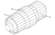
図1乃至図6は本発明の一実施形態を示すもので、図1は成形ドラムの斜視図、図2は成形ドラムの要部斜視図、図3乃至図5は第2ドラム部材を取付ける際の成形ドラムの要部側面断面図、図6は第2ドラム部材を取外す際の成形ドラムの要部側面断面図である。 1 to 6 show an embodiment of the present invention. FIG. 1 is a perspective view of a forming drum, FIG. 2 is a perspective view of a main part of the forming drum, and FIGS. 3 to 5 are views for attaching a second drum member. FIG. 6 is a side cross-sectional view of the main part of the forming drum when the second drum member is removed.
本実施形態の成形ドラムは、成形ドラムの外周面の一部を形成するように周方向に配列された第1ドラム部材10と、各第1ドラム部材10に成形ドラムの径方向外側からそれぞれ当接するように取付けられ、成形ドラムの外周面の他の部分を形成する複数の第2ドラム部材20と、第1ドラム部材10に対する第2ドラム部材20の成形ドラムの軸方向への移動を規制可能な移動規制機構30とを備えている。成形ドラムとしては、インナーライナー部材、カーカス部材、サイドウォール部材を巻付けてバンド部材を成形するバンド成形ドラムや、ベルト部材、トレッド部材を巻付けてベルト部材を成形するベルト成形ドラム等がある。
The molding drum of the present embodiment has a
各第1ドラム部材10は成形ドラムの軸方向に延びる板状部材から成り、成形ドラムの径方向内側を図示しない移動機構によって支持されている。移動機構は各第1ドラム部材10を成形ドラムの径方向に移動可能であり、各第1ドラム部材10の移動により成形ドラムが拡縮する。各第1ドラム部材10には、第1ドラム部材10を成形ドラムの径方向に貫通する挿入穴11と、挿入穴11から成形ドラムの軸方向に延びる係止溝12とが設けられている。挿入穴11は成形ドラムの軸方向に長く形成された長方形の穴である。係止溝12は成形ドラムの径方向内側に開口するとともに、挿入穴11側に開口している。
Each
各第2ドラム部材20は成形ドラムの軸方向に延びる板状部材から成り、成形ドラムにおける軸方向両端部が軸方向外側に向かって成形ドラムの径方向内側に傾斜している。各第2ドラム部材には成形ドラムの径方向内側に係止部材21がそれぞれ設けられている。係止部材21は、成形ドラムの径方向内側に向かって延びる径方向延設部21aと、径方向延設部21aの先端から成形ドラムの軸方向一方に向かって延びる軸方向延設部21bとを有する。軸方向延設部21bは第2ドラム部材20と所定の間隔をおいて成形ドラムの軸方向一方に向かって延びている。軸方向延設部21bの先端部は先端に向かって成形ドラムの径方向内側に傾斜している。また、各第2ドラム部材20には上下方向に貫通する係合孔20aがそれぞれ設けられている。
Each
係止部材21は第1ドラム部材10の挿入穴11に成形ドラムの径方向外側から挿入可能である。係止部材21を挿入穴11に挿入するとともに(図3参照)、第2ドラム部材20を第1ドラム部材10に対して成形ドラムの軸方向一方に移動させることにより(図4参照)、係止部材21が第1ドラム部材10の係止溝12内に挿入される。係止部材21の軸方向延設部21bは第1ドラム部材10の係止溝12に沿うように形成されている。係止部材21が係止溝12内に挿入されると、第2ドラム部材20が第1ドラム部材10に成形ドラムの径方向外側から当接するように、係止部材21が第1ドラム部材10に成形ドラムの径方向内側から係止する(図5参照)。また、係止部材21と係止溝12とが成形ドラムの周方向に係止する。
The
移動規制機構30は各第1ドラム部材10にそれぞれ設けられている。各移動規制機構30は、第1ドラム部材10を成形ドラムの径方向に挿通する係合部材としての係合ピン31と、係合ピン31を成形ドラムの径方向外側に向かって付勢する周知のコイルスプリングから成る付勢部材としてのスプリング32と、スプリング32を成形ドラムの径方向内側から支持するケース33とを有する。
The
係合ピン31は第1ドラム部材10を成形ドラムの径方向に挿通し、一端が第1ドラム部材10から成形ドラムの径方向外側に突出可能な円柱部31aと、円柱部31aの他端に設けられ、スプリング32と成形ドラムの径方向に当接するフランジ部31bとを有する。係合ピン31はスプリング32によって付勢されることにより、円柱部31aの一端が第1ドラム部材10から成形ドラムの径方向外側に突出する。第2ドラム部材20の係止部材21を係止溝12内の所定の位置まで挿入した際に、係合ピン31が第2ドラム部材20の係合孔20aに挿入される。
The
ケース33は第1ドラム部材10に成形ドラムの径方向内側から固定されている。
The
以上のように構成された成形ドラムにおいて、第1ドラム部材10に第2ドラム部材20を取付ける場合は、先ず、第1ドラム部材10の挿入穴11に第2ドラム部材20の係止部材21が成形ドラムの径方向外側から挿入されるように、第2ドラム部材20を第1ドラム部材に成形ドラムの径方向外側から当接させる(図3参照)。次に、第2ドラム部材20を第1ドラム部材10に対して成形ドラムの軸方向一方に移動させる。これにより、係止部材21の軸方向延設部21bが係止溝12内に挿入され、係止部材21の軸方向延設部21bが第1ドラム部材10に成形ドラムの径方向内側から係止する(図4参照)。また、係止部材21の軸方向延設部21bが係止溝12内の所定の位置まで挿入されると、移動規制機構30の係合ピン31が第2ドラム部材20の係合孔20a内に挿入され、第1ドラム部材10に対する第2ドラム部材20の成形ドラムの軸方向への移動が規制される(図5参照)。
In the molding drum configured as described above, when attaching the
次に、第1ドラム部材10から第2ドラム部材20を取外す場合は、移動規制機構30の係合ピン31を成形ドラムの径方向内側に向かって押しながら、第2ドラム部材20を第1ドラム部材10に対して成形ドラムの軸方向他方に移動させる(図6参照)。係合ピン31は第2ドラム部材20の係合孔20aの内径よりも小さい外径を有するシャフト22によって押すことができる。これにより、係合ピン31と係合孔20aとの係合が解除され、第2ドラム部材20を第1ドラム部材10から取外すことができる。
Next, when removing the
このように、本実施形態によれば、成形ドラムの外周面は各第1ドラム部材10及び第2ドラム部材20によって形成され、第2ドラム部材20の係止部材21を第1ドラム部材10の挿入穴11に挿入して第1ドラム部材10に成形ドラムの径方向内側から係止させるとともに、第1ドラム部材10と第2ドラム部材20との軸方向の移動を移動規制機構30によって規制することにより、第1ドラム部材10に第2ドラム部材20が取付けられることから、各第2ドラム部材20を各第1ドラム部材10に容易に着脱することができ、各第2ドラム部材20の交換によって成形ドラムの外周面形状を短時間で変更することができる。また、第2ドラム部材20の交換により成形ドラムの外周面形状を変更できることから、タイヤの種類に応じて第1ドラム部材を変更する必要がない。従って、多品種のタイヤを少量ずつ生産する場合の生産性の向上及び成形ドラムの製造コストの低減を図る上で極めて有利である。
Thus, according to this embodiment, the outer peripheral surface of the forming drum is formed by the
また、係止部材21に、第2ドラム部材20と所定の間隔をおいて成形ドラムの軸方向一方に向かって延び、第1ドラム部材10に成形ドラムの径方向内側から係止可能な軸方向延設部21bを設けたので、係止部材21を簡単な構造にすることができ、成形ドラムの製造コストの低減を図る上で有利である。
Further, the locking
また、移動規制機構30を、一端が第1ドラム部材10から径方向外側に向かって突出可能に設けられ、第1ドラム部材10から突出することにより第2ドラム部材20の係合孔20aと成形ドラムの軸方向に係合可能な係合ピン31と、係合ピン31を成形ドラムの径方向外側に向かって付勢するスプリング32とから構成したので、簡単な構造によって第1ドラム部材10に対する第2ドラム部材20の軸方向の移動を確実に規制することができ、成形ドラムの製造コストの低減を図る上で有利である。
In addition, the
尚、本実施形態では、第1ドラム部材10に成形ドラムの径方向に貫通する挿入穴11を設けたものを示したが、挿入穴11が第1ドラム部材10を貫通していない場合でも、挿入穴11が成形ドラムの径方向外側から内側に向かって延びるように設けられるとともに、係止溝12が挿入穴11から成形ドラムの軸方向に延びるように設けられていれば、第2ドラム部材20の係止部材21を第1ドラム部材10に係止させることができる。
In the present embodiment, the
また、本実施形態では、移動規制機構30を第1ドラム部材10に設けたものを示したが、図7及び図8に示すように、第2ドラム部材20に移動規制機構40を設けることも可能である。
In the present embodiment, the
この場合、移動規制機構40は、一端が第2ドラム部材20から成形ドラムの径方向内側に突出可能な係合部材としての係合ピン41と、係合ピン41を成形ドラムの径方向内側に向かって付勢する周知のコイルスプリングから成る付勢部材としてのスプリング42とを有する。一方、第1ドラム部材10には係合ピン41の一端を成形ドラムの径方向外側から挿入可能な係合孔10aが設けられている。第2ドラム部材20の係止部材21を係止溝12内の所定の位置まで挿入した際に、係合ピン41の一端が係合孔10aに挿入され、係合ピン41が係合孔10aに成形ドラムの軸方向に係合する。これにより、簡単な構造によって第1ドラム部材10と第2ドラム部材20との成形ドラムの軸方向への移動を確実に規制することができ、成形ドラムの製造コストの低減を図る上で有利である。
In this case, the
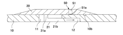
また、第2ドラム部材20に周知のボールプランジャ51から構成された移動規制機構50を設けることも可能である。
Further, it is possible to provide the
この場合、ボールプランジャ51は第2ドラム部材20に固定され、ボールプランジャ51のボール51aは第2ドラム部材20から成形ドラムの径方向内側に突出可能である。一方、第1ドラム部材10にはボールプランジャ51のボール51aと成形ドラムの軸方向に係合可能な凹状部10bが設けられている。第2ドラム部材20の係止部材21を係止溝12内の所定の位置まで挿入した際に、ボールプランジャ51のボール51aが凹状部10bに係合する。これにより、簡単な構造によって第1ドラム部材10と第2ドラム部材20との成形ドラムの軸方向への移動を確実に規制することができ、成形ドラムの製造コストの低減を図る上で有利である。
In this case, the
また、第2ドラム部材20に成形ドラムの軸方向への力を加えると、ボールプランジャ51のボール51が凹状部10bの傾斜面によって成形ドラムの径方向外側に移動し、ボール51aと凹状部10bとの係合を解除することができるので、第2ドラム部材20の交換をより短時間で行うことができる。
Further, when a force in the axial direction of the forming drum is applied to the
10…第1ドラム部材、10a…係合孔、10b…凹状部、11…挿入穴、12…係止溝、20…第2ドラム部材、21…係止部材、21a…径方向延設部、21b…軸方向延設部、30…移動規制機構、31…係合ピン、31a…円柱部、31b…フランジ部、32…スプリング、33…ケース、40…移動規制機構、41…係合ピン、42…スプリング、50…移動規制機構、51…ボールプランジャ、51a…ボール。
DESCRIPTION OF
Claims (4)
前記成形ドラムの周方向に配列され、成形ドラムの外周面の一部を形成する複数の第1ドラム部材と、
各第1ドラム部材にそれぞれ成形ドラムの径方向外側から当接するように取付けられ、成形ドラムの外周面の他の部分を形成する複数の第2ドラム部材と、
各第1ドラム部材にそれぞれ設けられ、成形ドラムの径方向外側から内側に向かって延びる挿入穴と、
各第2ドラム部材にそれぞれ設けられ、第2ドラム部材を第1ドラム部材に成形ドラムの径方向外側から当接させると、第1ドラム部材の挿入穴に成形ドラムの径方向外側から挿入され、第2ドラム部材が第1ドラム部材に当接した状態で第2ドラム部材を第1ドラム部材に対して成形ドラムの軸方向一方に移動させると、第1ドラム部材に成形ドラムの径方向内側から係止する係止部と、
第2ドラム部材の係止部が第1ドラム部材に係止している状態で第1ドラム部材に対する第2ドラム部材の成形ドラムの軸方向への移動を規制可能な移動規制機構とを備えた
ことを特徴とする成形ドラム。 In an expandable / contractible forming drum that winds a sheet-like member and forms it into a cylindrical shape,
A plurality of first drum members arranged in a circumferential direction of the molding drum and forming a part of an outer circumferential surface of the molding drum;
A plurality of second drum members that are attached to the respective first drum members so as to come into contact with each other from the outside in the radial direction of the molding drum, and form other portions of the outer peripheral surface of the molding drum;
An insertion hole provided in each first drum member, extending from the outside in the radial direction of the forming drum toward the inside;
Provided in each second drum member, and when the second drum member is brought into contact with the first drum member from the outside in the radial direction of the molding drum, the insertion hole of the first drum member is inserted from the outside in the radial direction of the molding drum, When the second drum member is moved in one axial direction of the molding drum with respect to the first drum member while the second drum member is in contact with the first drum member, the first drum member is moved from the radially inner side of the molding drum. A locking portion for locking;
A movement restricting mechanism capable of restricting movement of the second drum member relative to the first drum member in the axial direction of the forming drum in a state where the engaging portion of the second drum member is engaged with the first drum member; A forming drum characterized by that.
ことを特徴とする請求項1記載の成形ドラム。 The locking portion is provided with an axially extending portion that extends in one axial direction of the forming drum at a predetermined interval from the second drum member, and that can be locked to the first drum member from the radially inner side of the forming drum. The forming drum according to claim 1.
ことを特徴とする請求項1または2記載の成形ドラム。 The movement restricting mechanism is provided so as to be able to protrude from the first drum member toward the outside in the radial direction of the forming drum, and when the protrusion is protruded from the first drum member, the second drum member and the forming drum can be engaged in the axial direction. The forming drum according to claim 1 or 2, comprising a member and an urging member that urges the engaging member toward a radially outer side of the forming drum.
ことを特徴とする請求項1または2記載の成形ドラム。
The movement restricting mechanism is provided so as to be able to protrude from the second drum member toward the inside in the radial direction of the forming drum, and when it protrudes from the second drum member, the first drum member and the forming drum can be engaged in the axial direction. The forming drum according to claim 1 or 2, comprising a member and an urging member that urges the engaging member toward a radially inner side of the forming drum.
Priority Applications (1)
| Application Number | Priority Date | Filing Date | Title |
|---|---|---|---|
| JP2005346823A JP4962833B2 (en) | 2005-11-30 | 2005-11-30 | Molding drum |
Applications Claiming Priority (1)
| Application Number | Priority Date | Filing Date | Title |
|---|---|---|---|
| JP2005346823A JP4962833B2 (en) | 2005-11-30 | 2005-11-30 | Molding drum |
Publications (2)
| Publication Number | Publication Date |
|---|---|
| JP2007152574A JP2007152574A (en) | 2007-06-21 |
| JP4962833B2 true JP4962833B2 (en) | 2012-06-27 |
Family
ID=38237547
Family Applications (1)
| Application Number | Title | Priority Date | Filing Date |
|---|---|---|---|
| JP2005346823A Expired - Fee Related JP4962833B2 (en) | 2005-11-30 | 2005-11-30 | Molding drum |
Country Status (1)
| Country | Link |
|---|---|
| JP (1) | JP4962833B2 (en) |
Cited By (2)
| Publication number | Priority date | Publication date | Assignee | Title |
|---|---|---|---|---|
| CN109968707A (en) * | 2017-12-28 | 2019-07-05 | 东洋橡胶工业株式会社 | The winding method and winch spool of sheet element |
| KR20230027518A (en) * | 2021-08-19 | 2023-02-28 | 금호타이어 주식회사 | Tire belt building drum with variable curvature |
Families Citing this family (5)
| Publication number | Priority date | Publication date | Assignee | Title |
|---|---|---|---|---|
| FR2939711B1 (en) * | 2008-12-16 | 2012-07-27 | Michelin Soc Tech | MODIFYING ELEMENT FOR SHAPING A TIRED BLIND TIRE |
| FR2952849B1 (en) * | 2009-11-25 | 2012-02-24 | Michelin Soc Tech | DEVICE FOR ASSEMBLING PNEUMATIC BRAKE COMPRISING REMOVABLE ORGANS |
| JP5913337B2 (en) * | 2010-10-29 | 2016-04-27 | ピレリ・タイヤ・ソチエタ・ペル・アツィオーニ | Method and apparatus for building different series of tires |
| US20140048213A1 (en) * | 2012-08-15 | 2014-02-20 | The Goodyear Tire & Rubber Company | Sleeveless tire building drum with interchangeable width elements |
| JP7240906B2 (en) * | 2019-03-11 | 2023-03-16 | 旭化成株式会社 | Multilayer barrier shrink film and package |
Family Cites Families (14)
| Publication number | Priority date | Publication date | Assignee | Title |
|---|---|---|---|---|
| JPS5663087U (en) * | 1979-10-22 | 1981-05-27 | ||
| JPS6157334A (en) * | 1984-08-29 | 1986-03-24 | Yokohama Rubber Co Ltd:The | Molding drum |
| JPS6147620U (en) * | 1984-08-30 | 1986-03-31 | 横浜ゴム株式会社 | Forming drum drum diameter changing device |
| JPS62212135A (en) * | 1986-03-14 | 1987-09-18 | Yokohama Rubber Co Ltd:The | Split type tire molding drum for first stage molding |
| JPS6485742A (en) * | 1987-09-28 | 1989-03-30 | Ohtsu Tire & Rubber Co Ltd | Link type tire molding drum |
| JPH07102628B2 (en) * | 1991-04-30 | 1995-11-08 | 住友ゴム工業株式会社 | Ring member forming device |
| JP3193417B2 (en) * | 1991-10-07 | 2001-07-30 | 株式会社ブリヂストン | Drum for tire building |
| JP2691519B2 (en) * | 1995-03-17 | 1997-12-17 | 株式会社森鐵工所 | Device for fixing drum segment member to drum body of tire forming drum device and tire forming drum device |
| JPH091693A (en) * | 1995-06-23 | 1997-01-07 | Mori Tekkosho:Kk | Tire molding drum device and drum segment fixing method in said device |
| JP3549422B2 (en) * | 1998-12-11 | 2004-08-04 | 住友ゴム工業株式会社 | Tire component material holding device |
| US6488797B1 (en) * | 2000-05-12 | 2002-12-03 | Bridgestone/Firestone North American Tire, Llc | First stage run flat tire building drum and method of using same |
| JP4651885B2 (en) * | 2001-09-12 | 2011-03-16 | 株式会社ブリヂストン | Tire molding drum |
| JP4763940B2 (en) * | 2001-09-14 | 2011-08-31 | 住友ゴム工業株式会社 | Tire belt layer forming device |
| JP4226495B2 (en) * | 2004-03-05 | 2009-02-18 | 株式会社ブリヂストン | Tire molding drum and molding system, process design method, and manufacturing method of tire molded thereby |
-
2005
- 2005-11-30 JP JP2005346823A patent/JP4962833B2/en not_active Expired - Fee Related
Cited By (4)
| Publication number | Priority date | Publication date | Assignee | Title |
|---|---|---|---|---|
| CN109968707A (en) * | 2017-12-28 | 2019-07-05 | 东洋橡胶工业株式会社 | The winding method and winch spool of sheet element |
| CN109968707B (en) * | 2017-12-28 | 2022-01-04 | 东洋橡胶工业株式会社 | Method and apparatus for manufacturing belt for tire |
| KR20230027518A (en) * | 2021-08-19 | 2023-02-28 | 금호타이어 주식회사 | Tire belt building drum with variable curvature |
| KR102512950B1 (en) * | 2021-08-19 | 2023-03-23 | 금호타이어 주식회사 | Tire belt building drum with variable curvature |
Also Published As
| Publication number | Publication date |
|---|---|
| JP2007152574A (en) | 2007-06-21 |
Similar Documents
| Publication | Publication Date | Title |
|---|---|---|
| JP4962833B2 (en) | Molding drum | |
| US8720942B2 (en) | Steering wheel | |
| US20110120258A1 (en) | Steering wheel | |
| US20140225318A1 (en) | Spring assembly and manufacturing method therefor | |
| US20130334750A1 (en) | Spring assembly | |
| JP4275476B2 (en) | Tire manufacturing core | |
| CN207762075U (en) | Module units | |
| KR100545114B1 (en) | Tire mold | |
| US20150190976A1 (en) | Tire shaping drum | |
| US6886891B2 (en) | Wheel-cap mounting structure | |
| US5161860A (en) | Wheel cap | |
| US8727589B2 (en) | Vehicular lamp, vehicular component part for use in the same, and method of producing the vehicular component | |
| US20200282787A1 (en) | Top suspension mount comprising a removable insert, assembly comprising such a mount, and manufacturing process for such a mount | |
| CN107584787B (en) | Forming machine for forming bead core | |
| US20180017100A1 (en) | Slide bearing | |
| JP2009040557A (en) | Ribbon winding device | |
| US20130320666A1 (en) | Locking device for pipe member | |
| WO2015122057A1 (en) | Bearing device and method for manufacturing bearing device | |
| KR100811694B1 (en) | Device for fixing pedal switch of automotive vehicle | |
| CN105679608B (en) | Electromagnetic switch and vehicle starter | |
| JP2007196702A (en) | Sensor mounting structure, vehicle wheel and wheel/tire assembly | |
| US20180045564A1 (en) | Exterior fixing mechanism for analysis device | |
| WO2015068612A1 (en) | Bearing device and method for manufacturing bearing device | |
| KR101790485B1 (en) | Bead lock structure of greentire building drum | |
| CN110520643A (en) | Roller bearing unit with snap ring and the method for dismantling snap ring |
Legal Events
| Date | Code | Title | Description |
|---|---|---|---|
| A621 | Written request for application examination |
Free format text: JAPANESE INTERMEDIATE CODE: A621 Effective date: 20081028 |
|
| A977 | Report on retrieval |
Free format text: JAPANESE INTERMEDIATE CODE: A971007 Effective date: 20110418 |
|
| A131 | Notification of reasons for refusal |
Free format text: JAPANESE INTERMEDIATE CODE: A131 Effective date: 20110420 |
|
| TRDD | Decision of grant or rejection written | ||
| A01 | Written decision to grant a patent or to grant a registration (utility model) |
Free format text: JAPANESE INTERMEDIATE CODE: A01 Effective date: 20120302 |
|
| A01 | Written decision to grant a patent or to grant a registration (utility model) |
Free format text: JAPANESE INTERMEDIATE CODE: A01 |
|
| A61 | First payment of annual fees (during grant procedure) |
Free format text: JAPANESE INTERMEDIATE CODE: A61 Effective date: 20120315 |
|
| R150 | Certificate of patent or registration of utility model |
Free format text: JAPANESE INTERMEDIATE CODE: R150 |
|
| FPAY | Renewal fee payment (event date is renewal date of database) |
Free format text: PAYMENT UNTIL: 20150406 Year of fee payment: 3 |
|
| FPAY | Renewal fee payment (event date is renewal date of database) |
Free format text: PAYMENT UNTIL: 20150406 Year of fee payment: 3 |
|
| LAPS | Cancellation because of no payment of annual fees |