EP2697606B1 - Geodetic marking system for marking target points - Google Patents
Geodetic marking system for marking target points Download PDFInfo
- Publication number
- EP2697606B1 EP2697606B1 EP12714697.5A EP12714697A EP2697606B1 EP 2697606 B1 EP2697606 B1 EP 2697606B1 EP 12714697 A EP12714697 A EP 12714697A EP 2697606 B1 EP2697606 B1 EP 2697606B1
- Authority
- EP
- European Patent Office
- Prior art keywords
- marking
- unit
- air vehicle
- target point
- target
- Prior art date
- Legal status (The legal status is an assumption and is not a legal conclusion. Google has not performed a legal analysis and makes no representation as to the accuracy of the status listed.)
- Active
Links
- 238000000034 method Methods 0.000 claims description 39
- 230000005855 radiation Effects 0.000 claims description 32
- 230000008685 targeting Effects 0.000 claims description 30
- 238000012937 correction Methods 0.000 claims description 27
- 230000003287 optical effect Effects 0.000 claims description 25
- 238000005259 measurement Methods 0.000 claims description 22
- 238000012545 processing Methods 0.000 claims description 18
- 230000001276 controlling effect Effects 0.000 claims description 17
- 230000008859 change Effects 0.000 claims description 9
- 230000001133 acceleration Effects 0.000 claims description 7
- 230000001105 regulatory effect Effects 0.000 claims description 6
- 238000013500 data storage Methods 0.000 claims description 4
- 230000000694 effects Effects 0.000 claims description 4
- 238000004590 computer program Methods 0.000 claims description 3
- 230000003993 interaction Effects 0.000 claims description 3
- 230000033228 biological regulation Effects 0.000 claims description 2
- 238000005457 optimization Methods 0.000 claims description 2
- 230000033001 locomotion Effects 0.000 description 22
- 230000008569 process Effects 0.000 description 12
- 238000001514 detection method Methods 0.000 description 9
- 239000000725 suspension Substances 0.000 description 7
- 238000013459 approach Methods 0.000 description 6
- 239000003550 marker Substances 0.000 description 6
- 230000006870 function Effects 0.000 description 5
- 239000003973 paint Substances 0.000 description 4
- 239000007921 spray Substances 0.000 description 4
- 230000004913 activation Effects 0.000 description 3
- 238000005507 spraying Methods 0.000 description 3
- 238000003860 storage Methods 0.000 description 3
- 230000005540 biological transmission Effects 0.000 description 2
- 238000004364 calculation method Methods 0.000 description 2
- 238000004891 communication Methods 0.000 description 2
- 230000007613 environmental effect Effects 0.000 description 2
- 238000011156 evaluation Methods 0.000 description 2
- 238000003384 imaging method Methods 0.000 description 2
- 238000004519 manufacturing process Methods 0.000 description 2
- 230000002093 peripheral effect Effects 0.000 description 2
- 230000004044 response Effects 0.000 description 2
- 206010003830 Automatism Diseases 0.000 description 1
- 230000009471 action Effects 0.000 description 1
- 239000000853 adhesive Substances 0.000 description 1
- 230000001070 adhesive effect Effects 0.000 description 1
- 238000013479 data entry Methods 0.000 description 1
- 230000001419 dependent effect Effects 0.000 description 1
- 238000013461 design Methods 0.000 description 1
- 230000001605 fetal effect Effects 0.000 description 1
- 239000011888 foil Substances 0.000 description 1
- 238000007429 general method Methods 0.000 description 1
- 230000005484 gravity Effects 0.000 description 1
- 230000008447 perception Effects 0.000 description 1
- 239000011435 rock Substances 0.000 description 1
- 230000006641 stabilisation Effects 0.000 description 1
- 238000011105 stabilization Methods 0.000 description 1
- 238000002604 ultrasonography Methods 0.000 description 1
- 230000000007 visual effect Effects 0.000 description 1
Images


Classifications
-
- G—PHYSICS
- G01—MEASURING; TESTING
- G01C—MEASURING DISTANCES, LEVELS OR BEARINGS; SURVEYING; NAVIGATION; GYROSCOPIC INSTRUMENTS; PHOTOGRAMMETRY OR VIDEOGRAMMETRY
- G01C15/00—Surveying instruments or accessories not provided for in groups G01C1/00 - G01C13/00
-
- B—PERFORMING OPERATIONS; TRANSPORTING
- B64—AIRCRAFT; AVIATION; COSMONAUTICS
- B64C—AEROPLANES; HELICOPTERS
- B64C19/00—Aircraft control not otherwise provided for
-
- B—PERFORMING OPERATIONS; TRANSPORTING
- B64—AIRCRAFT; AVIATION; COSMONAUTICS
- B64C—AEROPLANES; HELICOPTERS
- B64C39/00—Aircraft not otherwise provided for
- B64C39/02—Aircraft not otherwise provided for characterised by special use
-
- G—PHYSICS
- G01—MEASURING; TESTING
- G01C—MEASURING DISTANCES, LEVELS OR BEARINGS; SURVEYING; NAVIGATION; GYROSCOPIC INSTRUMENTS; PHOTOGRAMMETRY OR VIDEOGRAMMETRY
- G01C15/00—Surveying instruments or accessories not provided for in groups G01C1/00 - G01C13/00
- G01C15/002—Active optical surveying means
-
- G—PHYSICS
- G01—MEASURING; TESTING
- G01S—RADIO DIRECTION-FINDING; RADIO NAVIGATION; DETERMINING DISTANCE OR VELOCITY BY USE OF RADIO WAVES; LOCATING OR PRESENCE-DETECTING BY USE OF THE REFLECTION OR RERADIATION OF RADIO WAVES; ANALOGOUS ARRANGEMENTS USING OTHER WAVES
- G01S17/00—Systems using the reflection or reradiation of electromagnetic waves other than radio waves, e.g. lidar systems
- G01S17/02—Systems using the reflection of electromagnetic waves other than radio waves
- G01S17/06—Systems determining position data of a target
- G01S17/42—Simultaneous measurement of distance and other co-ordinates
-
- G—PHYSICS
- G01—MEASURING; TESTING
- G01S—RADIO DIRECTION-FINDING; RADIO NAVIGATION; DETERMINING DISTANCE OR VELOCITY BY USE OF RADIO WAVES; LOCATING OR PRESENCE-DETECTING BY USE OF THE REFLECTION OR RERADIATION OF RADIO WAVES; ANALOGOUS ARRANGEMENTS USING OTHER WAVES
- G01S19/00—Satellite radio beacon positioning systems; Determining position, velocity or attitude using signals transmitted by such systems
- G01S19/01—Satellite radio beacon positioning systems transmitting time-stamped messages, e.g. GPS [Global Positioning System], GLONASS [Global Orbiting Navigation Satellite System] or GALILEO
- G01S19/03—Cooperating elements; Interaction or communication between different cooperating elements or between cooperating elements and receivers
- G01S19/07—Cooperating elements; Interaction or communication between different cooperating elements or between cooperating elements and receivers providing data for correcting measured positioning data, e.g. DGPS [differential GPS] or ionosphere corrections
- G01S19/071—DGPS corrections
-
- G—PHYSICS
- G01—MEASURING; TESTING
- G01S—RADIO DIRECTION-FINDING; RADIO NAVIGATION; DETERMINING DISTANCE OR VELOCITY BY USE OF RADIO WAVES; LOCATING OR PRESENCE-DETECTING BY USE OF THE REFLECTION OR RERADIATION OF RADIO WAVES; ANALOGOUS ARRANGEMENTS USING OTHER WAVES
- G01S19/00—Satellite radio beacon positioning systems; Determining position, velocity or attitude using signals transmitted by such systems
- G01S19/01—Satellite radio beacon positioning systems transmitting time-stamped messages, e.g. GPS [Global Positioning System], GLONASS [Global Orbiting Navigation Satellite System] or GALILEO
- G01S19/03—Cooperating elements; Interaction or communication between different cooperating elements or between cooperating elements and receivers
- G01S19/10—Cooperating elements; Interaction or communication between different cooperating elements or between cooperating elements and receivers providing dedicated supplementary positioning signals
- G01S19/11—Cooperating elements; Interaction or communication between different cooperating elements or between cooperating elements and receivers providing dedicated supplementary positioning signals wherein the cooperating elements are pseudolites or satellite radio beacon positioning system signal repeaters
-
- G—PHYSICS
- G01—MEASURING; TESTING
- G01S—RADIO DIRECTION-FINDING; RADIO NAVIGATION; DETERMINING DISTANCE OR VELOCITY BY USE OF RADIO WAVES; LOCATING OR PRESENCE-DETECTING BY USE OF THE REFLECTION OR RERADIATION OF RADIO WAVES; ANALOGOUS ARRANGEMENTS USING OTHER WAVES
- G01S19/00—Satellite radio beacon positioning systems; Determining position, velocity or attitude using signals transmitted by such systems
- G01S19/38—Determining a navigation solution using signals transmitted by a satellite radio beacon positioning system
- G01S19/39—Determining a navigation solution using signals transmitted by a satellite radio beacon positioning system the satellite radio beacon positioning system transmitting time-stamped messages, e.g. GPS [Global Positioning System], GLONASS [Global Orbiting Navigation Satellite System] or GALILEO
- G01S19/42—Determining position
- G01S19/51—Relative positioning
-
- G—PHYSICS
- G05—CONTROLLING; REGULATING
- G05D—SYSTEMS FOR CONTROLLING OR REGULATING NON-ELECTRIC VARIABLES
- G05D1/00—Control of position, course or altitude of land, water, air, or space vehicles, e.g. automatic pilot
- G05D1/10—Simultaneous control of position or course in three dimensions
- G05D1/101—Simultaneous control of position or course in three dimensions specially adapted for aircraft
- G05D1/102—Simultaneous control of position or course in three dimensions specially adapted for aircraft specially adapted for vertical take-off of aircraft
-
- B—PERFORMING OPERATIONS; TRANSPORTING
- B64—AIRCRAFT; AVIATION; COSMONAUTICS
- B64U—UNMANNED AERIAL VEHICLES [UAV]; EQUIPMENT THEREFOR
- B64U2101/00—UAVs specially adapted for particular uses or applications
- B64U2101/30—UAVs specially adapted for particular uses or applications for imaging, photography or videography
Definitions
- the invention relates to a geodetic marker with a positioning device, in particular a theodolite, a total station or a GNSS system, in particular with a GNSS reference station, and with an auto-mobile aircraft for marking a known destination according to claim 1, a method for controlling a Marking with a marking system according to the invention according to claim 6, an auto-mobile aircraft according to claim 10 for a marking system according to the invention and a marking arrangement according to claim 13 for a marking system according to the invention.
- geodetic surveying equipment include the theodolite, tachymeter and total station, also referred to as an electronic tachymeter or computer tachymeter.
- a geodetic measuring device of the prior art is disclosed in the publication EP 1 686 350 described. Such devices have electrosensitive angular and distance measuring functions which allow direction and distance determination to a selected target. The angle or distance variables are determined in the inner reference system of the device and must be for a absolute position determination may still be linked to an external reference system.
- Many geodetic applications measure points by placing specially designed targets. These usually consist of a pole with a targetable module, e.g. a reflector for defining the measuring section or the measuring point. These target objects are targeted by means of a surveying device, determining a direction and a distance to the objects and thus deriving a position of the objects.
- a targetable module e.g. a reflector for defining the measuring section or the measuring point.
- a marking of already known target points or of points whose position was defined in advance of a marking process can take place.
- the position or the coordinates of the points to be marked are known in this case and should be marked.
- a pole or a surveying rod is usually also used, which is guided by a user and positioned on a target point.
- the user can approach the target position of the target point on the basis of position information generated by the surveying device, whereby the surveying rod is automatically aimed at by the surveying device by a second person or by an automatism assigned to the surveying device.
- the user can mark the point.
- Modern surveying equipment such as a total station for such marking and surveying tasks have microprocessors for digital processing and storage of acquired measurement data.
- the devices are in the Usually produced in a compact and integrated design, with mostly coaxial distance and angle measuring elements and computing, control and storage units are integrated in one device.
- means are integrated for the motorisation of the target optics, for reflectorless distance measurement, for the automatic target search and tracking and for the remote control of the entire device.
- Total stations known from the prior art furthermore have a radio data interface for establishing a radio connection to external peripheral components, such as e.g. to a data acquisition device, which can be configured in particular as a handheld data logger, remote control unit, field computer, notebook, small computer or PDA.
- a data acquisition device which can be configured in particular as a handheld data logger, remote control unit, field computer, notebook, small computer or PDA.
- the data interface it is possible to output measured data stored and stored by the total station for external further processing, to read in externally acquired measurement data for storage and / or further processing in the total station, remote control signals for remote control of the total station or another external component, in particular in mobile field use . and output control software in the total station.
- a sighting telescope such as an optical telescope
- the scope is generally rotatable about a vertical standing axis and about a horizontal tilting axis relative to a base of the measuring device so that the telescope can be aligned by pivoting and tilting on the point to be measured.
- Modern devices can additively to the optical view channel one in the Riflescope integrated and, for example coaxially or parallel aligned camera for capturing an image, wherein the captured image in particular as a live image on the display of the display control unit and / or on a display of the peripheral device used for remote control - such as the data logger or the remote control unit - can be displayed.
- the optics of the sighting device may have a manual focus - for example, an adjusting screw for changing the position of a focusing optics - or have an autofocus, wherein the changing of the focus position, for example by servomotors.
- Automatic focusing devices for riflescopes of geodetic devices are eg from DE 197 107 22 , of the DE 199 267 06 or the DE 199 495 80 known.
- the target unit or a surveying rod provided with the target unit is aimed at or observed by a stationary position-determining unit such as, for example, a dead-center station.
- a stationary position-determining unit such as, for example, a dead-center station.
- an operator can be directed by marking on the display of the target unit to the target point by means of correlation between the currently measured from the stationary measuring station position data, including camera image for the mobile station, stored data with the intended position of the target point , eg by indication of direction by means of an arrow on the display.
- a device for further acceleration and simplification of a surveying or stakeout method is disclosed in the European patent application EP 2 431 708 A1 described.
- a remote control unit is described with a camera for recording a camera image in a defined recording direction, wherein by means of a position determination unit and the camera, the image data of the camera are brought in a coordinate system in spatial relation with the target points.
- This allows the operator to target the target more selectively, further reducing the duration of the survey process.
- this target search by the operator continues to require an active search of the target point position and an associated, in particular multiple, comparison of the Target point position with its current position or the position of the survey staff.
- WO 2008/124713 A2 discloses a geodetic marker system with a remotely controllable destination unit.
- the object of the present invention is to provide a surveying or marking system with associated units for the system as well as a corresponding method with which a marking of a target point is faster, easier and with a higher degree of automation, especially in a terrain that is difficult to access with a surveying bar. can be done.
- a specific object of the invention is to provide a way to prevent a visual comparison of its position or a position of a surveying bar with a target point position to be carried out by a user during a marking process.
- the invention relates to a geodetic marking system for marking a known target point with an auto-mobile, unmanned, remotely controlled target unit, wherein the target unit according to the invention is embodied by an aircraft, and with a geodetic position determining arrangement for the external Istpositionsbehlen the target unit, wherein the target unit is designed in that the target unit is, at least temporarily, largely positionally fixed, in particular floating, positionable. Furthermore, the target unit carries a, in particular modular removable, marking unit for marking the target point.
- the marking system has a control unit, wherein the control unit is configured such that depending on, in particular continuously determinable, external actual position and a known target point position of the target point, the target unit in a defined target position, in particular in a defined tolerance range around the target position, relative to Target point position, in particular continuously, automatically controlled positionable and that, taking into account the actual position, the target position and a defined marking direction of the marking unit to the target point, the marking unit to mark the target point is controllable, so that the target point in the defined marking direction with geodetic accuracy, ie to millimeters accurate or with a sub-centimeter accuracy, especially sub-millimeter accuracy, markable.
- Such a marking system can enable marking of target points in such a way that the positioning of the marking target unit runs completely automatically and thus no iterative approach of a user to a predetermined target point is required.
- the aircraft can be remotely controlled, for example by means of radio signals or signals that are wired, via infrared or via Bluetooth to the destination unit to be controlled to a defined position.
- a target unit for example, as an off-road vehicle, however, we used in the invention, an airworthy aircraft which can be positioned by a targeted control of motor-driven rotors, wherein the respective aircraft unmanned and simultaneously, in particular remotely controlled, by means of the intended motorization is movable.
- a position of the target unit can be determined with the marking system.
- a position determination arrangement is provided. This arrangement may be a total station, a theodolite, a tachymeter or e.g. have a GNSS system, wherein each one corresponding to the corresponding arrangement module is arranged target unit side.
- a position comparison can be carried out on the basis of the currently determined target unit position and / or the target unit or the aircraft can be controlled depending on the respective positions. From this information, further, a target position for the target unit can be derived and this target position can be defined as a target position for the target unit. The control of the target unit can then take place such that it is controlled to the target position and positioned there. A positioning of the target unit can thus at least temporarily take place as far as possible fixed in position, ie the target unit can hold independent of external influences over a temporary period of time, a stationary position without fluctuation. This can be special be achieved by a coordinated control of the target unit.
- a determination of the position of the target unit or a deviation from a predetermined position can be carried out continuously by the position-determining arrangement in contact with the target unit.
- a transmission unit assigned to the position determination arrangement can provide positioning signals that can be received by a receiver at the destination unit. If this arrangement has e.g. a GNSS transmitter or a GNSS system is used to accurately determine the position of the target unit, the target unit may have a GNSS receiver, by means of which a position information can be received and from which a position can be determined.
- a GNSS system that is customary for this purpose can be represented, for example, by GPS or GLONASS.
- a GNSS antenna can be arranged at the destination unit in order to be able to receive the signals assigned to the respective system.
- a GNSS reference station may be provided, which is also designed to receive GNSS signals and also provides reference data or correction data, for example for one of the known DGPS, RTK or VRS methods for increasing accuracy for position determination.
- a target unit adapted for such a reference system can thus also be designed to receive correction signals and perform a geodetic position determination taking these signals into account.
- the actual position of the target unit can be determined by a module arranged on the target unit, for example a reflector of one Surveying equipment, for example, from a total station or a theodolite, is targeted.
- the position of the surveying device can already be known, for example, by virtue of the fact that a calibration process was carried out on the surveying device and the device could thus carry out its own position determination by measuring known points. If a reflector at the target unit is now targeted by this surveying station, the direction to the target unit can be determined by determining the orientation of an emitted measuring beam and a distance to the target unit can be determined by means of a distance measurement carried out by means of the measuring beam.
- the relative position of the target unit to the surveying device can be determined unambiguously and accurately, and with knowledge of the position of the surveying device an absolute, in particular geodetically accurate, positioning of the target unit can be derived.
- the control of the unit can be performed.
- control data can be obtained from the position information, and by means of this, the target unit can be driven or flown to a defined desired position.
- the desired position can be determined in particular from the coordinates or position information of a destination point. If this represents, for example, a ground point in the terrain, the ground point itself can be defined as the target point, which - as regards an alternative, non-inventive aspect - can be approached by a vehicle.
- a target area around the target position can be defined here, with the target point as reached as soon as the vehicle or the position of the vehicle indicating component is in the target area.
- a target position can be defined, for example, between two and ten meters vertically above the ground point or at a certain angle, in particular within a defined Angular range, and distance to the ground point is located.
- a target or target area which has a defined position tolerance, are clamped around the target position, wherein the target position is considered reached when the aircraft or in turn the component of the aircraft, which indicates its current position, in the Target range is located.
- the aircraft can maintain a variable within a predefined setpoint range by compensating counter-control against an externally acting deflection force.
- a described positioning of the target unit with geodetic accuracy can be used for different applications.
- the target unit is equipped with a marking unit or carries such a marking unit.
- the marking unit can be embodied as an optical marking unit, in particular as a laser beam source, the target point being optically visibly marked by emitting the laser beam, and / or a marking of the target point can be made by attaching a panel made of color, e.g. Spray paint or ink jet, make existing mark.
- the marking of the target point may be accomplished by subjecting an article, e.g. a magnet is "dropped" at the target point position by the target unit and thus placed on the target point.
- an adhesive marking for example a label or a reflector foil, may be applied to the target point or a projectile, e.g. a nail from the target unit are fired so that is marked by an impact of the projectile at the target point this.
- a control of the target unit and the marker for marking can be done by means of a control unit.
- This control unit can on the one hand control the positioning of the destination unit by means of a, in particular constantly running, comparison of the current position of the target unit (actual position), the target position and the target point position.
- the target unit can be moved to the desired position or desired range by the control unit, for example by generating control data, as a function of these positions and the target unit can be positioned or held there when the desired range is reached.
- the relative Be known ratio of actual, target and target point position and continue to be controlled by means of the control unit with additional consideration of a marking of the marking this unit so that the marking of the target point is done.
- the marking unit is activated and / or controlled so that the target point is marked when, taking into account the actual position of the target unit and the marking of the marking unit, the target point is exactly met or hit with a mark generated by the marking unit.
- the data processing that takes place for this purpose can be carried out, for example, on the target unit, on the surveying device or on a remote control unit.
- the position determination arrangement can have at least one transmission unit for transmitting positioning signals and the target unit can be configured such that the positioning signals, in particular by means of a GNSS antenna, can be received and the actual position of the destination unit can be determined from the positioning signals.
- a geodetically accurate position determination of the target unit can be made, which can be detected and taken into account for the positioning of the target unit.
- This type of position determination also assumes that the positioning signals provided by the transmitting unit can be received by the destination unit, ie that the signals are not blocked or blocked by any obstacles existing between the transmitting unit and the destination unit.
- the transmitting unit can be embodied as a GNSS transmitter, in particular a GNSS satellite, in particular a GPS, GLONASS or Galileo satellite, and the positioning signals can be embodied by GNSS signals or the transmitting unit can have a pseudo-satellite module and the positioning signal be embodied by pseudo-satellite signals. If, for example, the position of the aircraft and the marking of a target point in a closed space, for example in a production hall, take place, then often no GNSS signal can be received there from the destination unit. In this case, a positioning by means of a pseudo-satellite module, so-called pseudolites or pseudo-satellites, be made in the hall.
- the pseudolites can be placed at respectively known positions and can transmit position information therefrom by means of the pseudo-satellite signals, for example in a signal format similar to a GNSS signal, by means of which a position determination on the part of the target unit can again be carried out.
- the signals may allow a determination of a relative position within, for example, a coordinate system or an object coordinate system representing the manufacturing space.
- an absolute, global position determination of the target unit can also be indirectly feasible.
- signals from four pseudolites can be received by the aircraft, in particular, with a common time base of the signals, the reception of three signals makes a position determination exactly feasible. For example, when positioning the target unit in a known height, two signals for position determination may be sufficient.
- the position-determining arrangement may have a GNSS reference station for transmitting GNSS correction signals and the target unit may be designed such that the GNSS correction signals can be received and the actual position of the destination unit from the received GNSS signals and the GNSS Correction signals are determinable.
- the thus additionally provided correction signals enable a more exact absolute position determination of the target unit.
- the aircraft can have a reflector and the position-determining arrangement a geodetic surveying device, in particular the theodolite or total station.
- the surveying device has at least one targeting device, in particular a target telescope, wherein the targeting device is pivotable relative to a base of the surveying device for changing its orientation, in particular motorized, and at least one emission unit defining an optical target axis and a radiation source for emitting an optical measuring beam for distance measurement parallel, in particular coaxial, to the optical target axis has.
- an angle measurement functionality for high-precision detection of the alignment of the target axis and evaluation means for data storage and control of the alignment of the target device are provided.
- the measuring beam can thus be aligned with the reflector so that the actual position of the target unit can be determined.
- the Measuring radiation to the measuring unit reflected back and recorded there.
- a distance from the surveying device to the target unit or to the reflector can be determined from this reflected measuring radiation and the position of the target unit can be specified taking into account the alignment of the targeting device.
- a signal which can be transmitted to the destination unit in particular wherein the signal is embodied by a radio signal, a signal modulated by a laser beam or an electronic signal, can be position information, the position information being convertible into control data in a first processing unit assigned to the destination unit, or the control data itself, wherein the control data can be determined from the position information by means of a second processing unit assigned to the surveying device.
- the detected position information can be directly transmitted e.g. be transmitted by radio to the destination unit and destination unit side, the position information for control, in particular for the generation of control data, are used.
- the position information can be further processed directly on the side of the surveying device and based on this information control signals or control data for controlling the target unit to be transmitted to this.
- the target unit embodied as an aircraft can also be positioned, at least temporarily, largely horizontally so that it can be positioned in a fixed position, in particular an effect on the positioning by external influences, in particular air flow, pressure and / or temperature fluctuation, can be compensated in the vertical direction.
- a position compensation can ensure a correct and usable positioning of the destination unit. If, for example, a wind force or a wind direction changes, which is taken into account for a floating positioning of the aircraft, a counter-control with a drive unit, for example a rotor of the aircraft, can take place in response thereto. It may be advantageous if the aircraft largely holds its horizontal position in a backlash and compensation takes place a correction or repositioning mainly in the vertical direction.
- the marking system can have a remote control unit for controlling the destination unit, in particular wherein the remote control unit has a display for displaying information.
- control-relevant data can be transmitted and / or received to the destination unit, or else a manual control of the destination unit by an operator can take place.
- a communication and power supply between the remote control unit, the target unit and / or a surveying device can be done for example via a cable.
- data processing may be performed for control on the remote control unit, the remote control unit e.g. as a PDA, smartphone or tablet PC can be realized.
- a marking of positions of boreholes on a wall can be carried out with the marking system.
- a digital model of a building or room can be used in the system be deposited, depending on the model, a definition of the positions of the holes can be made.
- the target unit can also be positioned relative to a borehole position, for example likewise depending on the digital model, and thereby effect the marking of the hole, for example by visible laser radiation.
- an operator of the system can now set the respective borehole or mark the position manually and subsequently control the target unit to the next borehole position or automatically assume the next position. There again, such a mark can be made and thus the holes are sequentially marked or drilled.
- the target unit may have a sensor unit for determining an orientation and / or the actual position of the target unit, in particular an inclination sensor, a magnetometer, an acceleration sensor, a rotation rate sensor and / or a speed sensor.
- the target unit may have a component indicating the orientation of the target unit
- the marking system may have a detection device, in particular a camera, for detecting and / or targeting the component and for determining the orientation of the target unit from the position and arrangement of the component.
- the determination of position and orientation of the aircraft can be done for example by a laser tracker.
- the orientation of the aircraft may be detected by a measurement of the location of markers disposed on the unit by the scanning unit. From the knowledge of the location and the arrangement of the markers and the knowledge of the position of the laser tracker relative to the aircraft, the Orientation of the aircraft are derived. From the position and the orientation information follows the knowledge of the situation in space. Such a general method for orientation determination is described for example in US Pat WO 2006/097408 described.
- the orientation may also be determined by means of an offset of a receiver to a measuring beam axis which is defined by a measuring beam aimed at the receiver, the optical system of the receiver thereby having only a limited opening angle.
- the determination of the alignment can be carried out by a method, wherein a emitting of a laser beam in the direction of a detector arranged on the target unit takes place and an emission direction of the laser beam is defined. This is followed by determining an impact point of the laser beam on the detector. From this impact point, the direction of incidence is derived. Based on a linking of the direction of incidence with the direction of emission, it is now possible to determine the orientation of the detector relative to the laser source and thus the target unit.
- a method is for example from the WO 2008/138507 known.
- the position of the destination unit is tracked and a direction of movement is determined from the position changes. Based on the assumption that the direction of movement corresponds to a specific orientation of the destination unit, information about the orientation of the destination unit can be derived therefrom.
- the position change can be determined, for example, by means of a continuous position determination by GPS.
- the position and rotational position or orientation of an object in space can be effected by means of an optical measuring device.
- the measuring device can have an imaging optics and a detector which is spatially resolving in two dimensions.
- the object or the destination unit can have a known code pattern, eg a barcode or pseudo-random code, and the pattern detected with the measuring device can be evaluated. Depending on the location of the detected code can be closed by the respective location of the target unit in the room.
- a method corresponding to this principle is used, for example, in US Pat EP 1 066 497 revealed.
- the marking system according to the invention may also have a control functionality, wherein the actual position of the aircraft is continuously determined during execution of the control functionality controlled by the control unit during a Markierzeitmits.
- This actual position can be determined by means of an interaction of the geodetic surveying device with the reflector and / or by means of the sensor unit and the aircraft based on it are kept stable so that the target point is continuously marked throughout the Markierzeittens by means of the marking unit with geodetic accuracy.
- the positioning of the aircraft can be regulated such that the aircraft during the entire Markierzeitraps present in the desired position and / or the marking direction is continuously adjusted and / or in an at least temporarily non-complies the marking of the target point, an error is output.
- a method for controlling a geodetic-precision marking of a known destination point has an auto-mobile, unmanned, remotely controllable aircraft as destination unit, wherein an external actual position of the destination unit, in particular continuously, is determined.
- the target unit carries a, in particular modular detachable, marking unit for marking the target point.
- the target unit is positioned in a defined target position, in particular in a defined tolerance range around the target position, relative to the target point position, in particular continuously, depending on, in particular continuously determined, external actual position and a known target point position of the target point.
- the marking unit for marking the destination point is controlled so that the destination point is marked in the defined marking direction with geodetic accuracy.
- an aircraft target unit
- Such positioning may provide a general basis for further action to be performed on the destination unit.
- the marking of the target point can take place with the present invention.
- the target unit is initially controlled as a function of its actual position and the target point position in a specific position - in the target position - and positioned there largely fixed position.
- the marking unit is controlled in dependence on the actual position, the target position, in particular depending on whether the target unit is in the desired position or in the desired range, and the marking of the marking such that the target point is marked by the marking.
- positioning signals can be received by the target unit and the external actual position, in particular an alignment of the target unit, can be determined from the positioning signals, in particular wherein the positioning signals are embodied by GNSS signals, pseudo-satellite signals and / or GNSS correction signals and the actual position is determined from the GNSS signals and / or the GNSS-like signals, in particular taking into account the GNSS correction signals.
- a measuring beam can be reflected on the aircraft side and the outer actual position can be determined by means of the reflected measuring beam.
- an absolute, geodetically accurate position of the target unit can be determined and, based on this, a positioning thereof can be carried out. If it is necessary to ensure that the signals can be received when positioning signals or GNSS signals are used, a position determination can be carried out in the case of reflection of a measuring beam independently of possible signal shielding.
- an orientation of the target unit in particular in pitch, roll and yaw direction, and / or a distance to an object, in particular to an obstacle, determined, and / or an image, in particular wherein the image has the target point , are recorded.
- the target point can thus be located in the field of view of the camera.
- a determination of the orientation of the target unit can, for example, be taken into account in a control for positioning or be used for a required or for a positioning in a defined orientation.
- obstacles in a flight path or a route of the destination unit can be detected and either, in particular automatically, bypassed or the destination unit can be positioned taking into account the respective obstacle.
- images of an environment in which the target unit is moved can be detected.
- a movement or a path along which the destination unit moves can also be determined and, as a result, a continuous determination of the actual position can be derived.
- the target unit in the case of co-detection of the target point on an image, the target unit can furthermore be controlled or placed at a target position on the basis of the image information.
- a user can thus have image information available on the basis of which the target unit can also be controlled manually.
- the marking of the target point can take place with optically visible radiation and a radiation direction of the radiation can lie parallel, in particular coaxially, to the marking direction.
- the Marking radiation can be activated upon reaching the desired position and proper alignment of the marking and emitted continuously and / or pulsating to indicate the target point.
- the marking direction of the marking unit can be aligned in parallel, in particular automatically, with respect to the perpendicular direction and / or relative to the alignment of the target unit, in particular with the marking unit being gimbaled and / or the target unit having alignment means for the defined alignment of the marking direction, in particular wherein the marking unit is pivoted in two, in particular in three, axes. Due to the gimbal suspension, the marking direction can be automatically aligned parallel to the perpendicular direction, ie parallel to the gravity vector, the earth and has the consequence that an exact alignment of the target unit in a vertical positioning over the target point for marking the target point is not mandatory.
- the marking direction may be aligned by the alignment means such that the target point is marked at a certain angle to the plumb line.
- the alignment means can enable pivoting or rotation of the marking direction by up to three axes and thus not only punctiform marking of the target point, but also a marking by a pattern, which, for example, arises during rapid movement of a designed as laser radiation marker.
- a path in the context of the method, can be defined by waypoints, wherein the destination unit is moved along the path, in particular wherein an optimization of a path course, in particular automatically, takes place and / or the path has the destination point and / or the desired position, and / or marking the position of the waypoints as intermediate destination points continuously along the path.
- waypoints can be staked out, which define the way to a destination point and / or which intermediate destination points form and thus should also be marked.
- the movement path of the destination unit can be optimized, in particular if known obstacles are bypassed in advance by the definition of the waypoints.
- the marking of the waypoints can also by means of an optical system, such as a visible laser beam, or by means of a color marking, for example with a paint or spray paint done.
- the marking can run fully automatically, ie, the target unit moves continuously from waypoint to waypoint and makes, if necessary, each mark before or semiautomatic, ie the target unit automatically moves to a waypoint and holds the position to a user a signal for positioning on next waypoint there.
- information and / or control commands in particular the destination point position, can be entered into the destination unit, and / or information, in particular the captured image, in particular on a display, can be output.
- the actual position of the aircraft can be continuously determined during a regulation during a marking time window and the aircraft can be kept stable based on the measuring beam reflected by the aircraft device or by means of a sensor unit for determining an orientation and / or the actual position of the aircraft the target point is continuously marked during the entire marking time window by means of the marking unit with geodetic accuracy.
- the positioning of the aircraft can be regulated such that the aircraft is present in the desired position during the entire Markierzeitfen ⁇ and / or the marking direction are continuously adjusted and / or carried out at an at least temporarily non-complies the marking of the target point an error output.
- Another object of the invention is an auto-mobile, unmanned, remote-controlled target unit, wherein the target unit according to the invention is designed as an aircraft, in particular as a drone, for use in a marking system according to the invention.
- the target unit is also designed in such a way that the target unit is at least temporarily largely fixed in position, in particular floating, positionable. Furthermore, position information for determining an external actual position of the destination unit and for generating control data and / or the control data can be transmitted directly to the destination unit.
- the destination unit carries a marking unit for marking one destination point, in particular wherein the marking unit is modularly detachable, and the control data are configured such that, depending on the, in particular continuously determinable, external actual position and a known destination point position of the destination point, the destination unit in a defined target position , in particular in a defined tolerance range around the target position, relative to the target point position, in particular continuously, can be positioned.
- the marking unit can be controlled to mark the target point, so that the target point can be marked in the defined marking direction with geodetic precision.
- the target unit according to the invention can be embodied, for example, by an aircraft which can be positioned largely in a positionally stable manner by means of at least two rotors and / or nozzles.
- the Destination unit for example, by an all-terrain vehicle, which can be controlled to drive to a target position and is positioned so be embodied.
- the destination unit may be e.g. be remotely controlled by means of radio signals, via a laser beam or by cable, the target unit itself being unmanned and automobile, i. has a motorized drive, which provides an independent locomotion of the target unit is executed.
- the destination unit additionally has a marking unit with which a marking of the destination point can be carried out.
- the target unit can be controlled and placed taking into consideration the own position (actual position), the target point position and a position in which the target unit is to be positioned (target position). With an additional consideration of the marking direction in the control data, the destination point can then be geodetically accurately marked by the marking unit.
- a destination unit can have a receiver for positioning signals, in particular a GNSS antenna, and a processing unit for determining an actual position of the destination unit from the positioning signals.
- the positioning signals may be embodied by GNSS signals, in particular where the GNSS signals are represented by GPS, GLONASS or Galileo signals, pseudo-satellite signals and / or GNSS correction signals and the actual position from the GNSS signals and / or the GNSS-like signals, in particular taking into account the GNSS correction signals, be determinable.
- the target unit may have a reflector. By means of such receivers or by means of Reflectors, an absolute position of the target unit can be determined by either the positioning signals or GNSS signals detected and converted into position information or the reflector is targeted and thereby the position of the target unit is determined.
- a target unit according to the invention may further comprise a sensor unit for determining an orientation and / or the actual position of the target unit, in particular a tilt sensor, a magnetometer, an acceleration sensor, a rotation rate sensor and / or a speed sensor.
- a sensor unit for determining an orientation and / or the actual position of the target unit, in particular a tilt sensor, a magnetometer, an acceleration sensor, a rotation rate sensor and / or a speed sensor.
- the target unit according to the invention can have a sensor for measuring the distance to objects, in particular radar, whereby, for example, obstacles can be detected by means of this sensor and thus taken into account or avoided during the movement of the target unit.
- the target unit may further comprise an optical detection unit, in particular a camera, for detecting an image, in particular wherein the image has the target point or the target point is located in the image field.
- this detection unit such as a video camera
- one or more images of a camera environment or an aerial photograph of a terrain can be detected and detected by image processing processes such as a change in the position of the target unit.
- the image information can be used to perform the control of the target unit, in particular towards a defined position, and / or an operator provide image information for measurement or marking processes or images for documentation of a surveying process.
- a position determination of the destination unit can take place as a function of captured images.
- a series of images can be captured whose image areas each partially overlap.
- the overlapping areas can, for example, be matched by a comparison of patterns captured on the images, in particular by image processing or comparison of the overlapping areas of the images.
- the relative position of an image to a subsequent image can be determined and a movement progress of the image acquisition unit from the size of the Studentslappuhgs Kunststoffs and a rotation angle by which the subsequent image image processing must be rotated so that a match of a prominent pattern can be achieved in the overlap area and hence the destination unit.
- a recognition of distinctive waypoints, whose coordinates are known, take place and from this an absolute horizontal position can be determined directly.
- such a position determination for example, in case of failure of the GNSS system or coverage of the GNSS signals, so that no position determination is possible, be feasible, with a coordinatively known starting point of the target unit can be taken into account in the determination.
- zoom factors of one or more images can be compared with each other and, in turn, be deduced from any pattern matching a height change.
- the target unit can be identified on the basis of a time-invariant texture, e.g. Positionally stabilize on the ground.
- This stabilization can in turn be carried out by a comparison of temporally spaced detected images such that a position correction of the target unit with the aim of bringing a currently detected image or a texture detected on the image on a temporally previously acquired image takes place , This may at the same time support the precision of the marking or, in the event of a temporary interruption of a control signal, make the target unit positionable.
- an autonomous movement back of the destination unit to the respective starting point can take place.
- This movement back may be done by moving along a route derived from the images or moving through image comparison.
- the image comparison can be executed as a comparison of captured images of moving with images captured on the move back.
- a target unit according to the invention for defined, in particular automatically parallel, alignment of the marking direction can have a cardan suspension and / or alignment means for the marking unit, in particular wherein the marking unit can be pivoted in two axes, in particular in three axes.
- the marking unit can furthermore have a beam source for emitting optically visible radiation and the beam source can be arranged such that an emission direction of the optical radiation runs parallel, in particular coaxially, to the marking direction.
- a continuous alignment of the marking direction or the optically visible radiation for example a laser radiation in the visible wavelength range, be realized parallel to the direction of the earth so that when positioning the marker unit carrying target vertically above a ground point of this ground point upon activation of the marking unit, ie, for example, when emitting the laser radiation is automatically marked.
- the marking direction can be aligned at a defined angle relative to the perpendicular direction and thus also be made to mark a target point, if the target unit is not vertically above the target point, but is offset from the perpendicular direction.
- the marking of the spot may still be performed.
- a targeted alignment of the marking direction to compensate for or compensate for caused by external influences unwanted changes in position of the target unit can be done so that despite such an offset, a marking of the target point can be done.
- the destination unit can be an input unit, in particular a keyboard, touch-sensitive display and / or data interface, for inputting information and / or control commands, in particular the destination point position, and / or an output unit, in particular a display, for outputting information, in particular that of the camera captured image.
- Such input options can one Allow or facilitate the input of information needed to work with the target device.
- a target point position can be stored and the target unit automatically and automatically approach this position and thus make fully automatic marking of a target point feasible.
- Corresponding position information can also be transmitted via the data interface in and / or out of the destination unit.
- An additionally provided display may further facilitate data entry for a user and / or provide, for example, environmental information.
- a remote control unit for controlling the destination unit can also be assigned to a target unit according to the invention, in particular wherein the remote control unit has a display for displaying information and / or the image captured by the camera.
- This remote control unit may provide the user with additional or alternative input and output means.
- a programming of the target unit can be done by means of this remote control unit and, for example, displayed on a display on the remote control unit target image side captured image so that a continuously generated environmental image for control, in particular to a manual control by an operator, can be used.
- a marking arrangement according to the invention for marking a known target point and for use in a marking system according to the invention has a remotely controllable marking unit and a geodetic positioning arrangement, in particular theodolite or fetal station, for determining the external position of the marking unit, wherein an external actual position of the marking unit Marking, in particular continuously, by means of the position determination arrangement can be determined on.
- the marking arrangement has a control unit, wherein the control unit is configured in such a way that the target unit in a defined target position, in particular in a defined tolerance range around the target position relative to the target point position, depending on the, in particular continuously determinable, external actual position and a known target point position of the target point , in particular continuously, can be positioned.
- the control unit is configured such that, taking into account the actual position, the desired position and a defined marking direction from the marking unit to the target point, the marking unit is controllable, so that the target point can be marked in the defined marking direction with geodetic precision.
- the absolute and current position of the marking unit can be determined, in particular so that the marking unit can be tracked and as a result the position of this continuously or continuously detected.
- the marking unit can be controlled in dependence on these two positions so that it can be positioned in a specific desired position.
- the marking unit can be further controlled so that, taking into account the current marker unit position, in particular in accordance with the desired position, and an orientation of the marking, the marking of the target point can be done by the marking.
- the positioning arrangement of the marking arrangement according to the invention can have at least one transmitting unit for emitting positioning signals and the marking unit can be configured such that the positioning signals, in particular by means of a GNSS antenna, can be received and the actual position of the marking unit can be determined from the positioning signals.
- the transmitting unit can be embodied as a GNSS transmitter, in particular a GNSS satellite, in particular a GPS, GLONASS or Galileo satellite, and the positioning signals can be embodied by GNSS signals.
- the transmitting unit may further comprise a pseudo-satellite module and the positioning signal may be embodied by pseudo-satellite signals.
- the position-determining arrangement can have a GNSS reference station for transmitting GNSS correction signals
- the marking unit can be configured such that the GNSS correction signals can be received and the actual position of the marking unit can be determined from the received GNSS signals and the GNSS correction signals.
- Another position determination possibility according to the invention can be realized with the position determination arrangement with a geodetic surveying device, in particular theodolite or total station, wherein the position of the marking unit is indicated by a reflector in space with high precision.
- an angle measurement functionality for high-precision detection of the alignment of the target axis and evaluation means for data storage and control of the alignment of the target device are provided.
- the measuring beam can thus be aligned with the reflector so that the actual position of the marking unit can be determined.
- determining a position with a surveying device a possible limited reception of GNSS signals and an associated limited or impossible position determination can be replaced and the determination can nevertheless be carried out.
- the determination of the current position of the marking unit can be carried out when there is a line of sight between the surveying device and the marking unit.
- the marking unit can have a data interface, in particular embodied by radio module, Bluetooth interface, infrared interface and / or Com port, for controlling and / or exchanging information with an auto-mobile, unmanned, remotely controllable destination unit embodied as an aircraft ,
- the data interface can serve to connect the marking unit to a destination unit and thus to provide a variable positioning, in particular an automatic and / or controllable positioning, of the marking unit. Any information between the two components can be exchanged via the data interface and thus, for example, a feedback for the controller to a User or a direct control of the destination unit.
- Another object of the invention is a computer program product according to the invention, which is stored on a machine-readable carrier, or computer data signal, represented by an electromagnetic wave, with program code for carrying out a method according to the invention, in particular if the program is executed in an electronic data processing unit ,
- the computer program product or computer data signal can be designed in such a way that it contains control instructions, in particular in the form of algorithms, with which a method according to the invention for controlling a geodesically accurate marking of a known destination with an auto-mobile, unmanned, remote controlled target unit can be done.
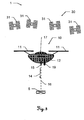
- FIG. 1 shows a surveying system 50 of the prior art.
- the system 50 has a surveying device 51 and a surveying bar 52.
- a reflector 54 On the surveying rod 52, a reflector 54, a releasably attachable to the rod 52 controller 56 with a display 57 and on a point tapered lower end 58 are further provided.
- An aiming device of the surveying device 51 can emit a measuring beam 55 with which the reflector 54 can be aimed and thus a distance from the surveying device to the surveying bar can be determined.
- a surveying device 51 according to the prior art can have protractors by means of which an orientation of the surveying device 51 can be detected.
- a relative position ie a position determination in an inner coordinate system of the surveying device 51
- the surveying rod 52 to the surveying device 51 clearly, taking into account the orientation and the distance to be determined.
- an absolute position ie a position in an external coordinate system
- After setting up the surveying device 51 it can be measured in an environment and thus the absolute position of the measuring device 51 can be determined.
- Such a calibration can be done, for example, by measuring already known target points in the measurement environment.
- an absolute position determination of any point detected or targeted by the surveying device 51 can now be carried out.
- the surveying device 51 may comprise a camera, with which an image of the measuring environment, in particular in the direction of the targeting direction, can be detected.
- a camera image produced in this way can be displayed, for example, on the measuring device side or on the display 57 of the controller 56.
- Such a measurement system 50 can be used, for example, for measuring objects.
- the surveying bar 52 can be placed at a point 59 on the object to be measured by a user and vertically aligned.
- the reflector 54 can then be targeted by the surveying device 51 and its position can be determined. Taking into account the length of the rod 52, the position of the point 59 can be calculated unambiguously and accurately and its coordinates determined.
- Another use of the surveying system 50 is the marking of already known destination points 59.
- the point coordinates can be stored in the system 50, wherein a user by finding and placing the survey rod 52 on the destination point 59 locate the destination point 59 and then mark.
- this marking operation can be carried out by a user, especially when the user can simultaneously guide the surveying bar 52 and obtain information about the current position of the surveying bar and the destination point position. This can be realized by a radio link between the controller 56 and the surveying device 51.
- the position of the rod 52 and the reflector 54 can be continuously determined and transmitted to the controller 56.
- this position By comparing this position with a stored target point position - again by including the length of the rod 52 - the user can thus approach or be guided to the desired target point. If the target point 59 is reached, this can be marked, for example, by means of a pile or by means of spray paint.
- the surveying device 51 can, in particular, be automatically aligned and "coupled” to the reflector 54 of the surveying rod 52 for facilitating the setting-off process, so that an automatic target tracking of the rod 52 can take place.
- target tracking can be realized by means of an automatic target recognition device (ATR) integrated into the surveying device 51.
- ATR automatic target recognition device
- the deviation of a laser beam reflected by the reflector 54 from a zero position on a photodiode can be detected such that a direction of movement of the deviation Reflector 54 can be derived relative to the surveying device 51 and the surveying device 51 correspondingly track this movement or the alignment of the surveying device 51 can be adjusted to the reflector 54, so that the deviation is minimized on the photodiode.
- FIG. 2 shows a marking system 1 according to the invention with an aircraft 10, which represents the target unit 10 of the system 1 according to the invention, and a surveying station 20, wherein the surveying station 20 embodies the position-determining arrangement.
- the aircraft 10 has two drive units 11, in particular rotors, which allow at least temporary, largely stationary positioning of the aircraft 10 in a defined position, wherein the positioning can be done vertically above a defined point floating.
- the aircraft 10 can be aligned and / or moved in one direction or a direction of movement can be changed.
- the target unit 10 has a sensor unit 12, wherein the sensor unit 12 may have a magnetometer, an at least biaxial inclination sensor, acceleration sensors and / or a gyroscope.
- the sensor unit 12 may thus provide a determination of an inclination or orientation of the target unit 10.
- sensors for distance measurement 7 to objects 9, in particular obstacles are provided in order to prevent a collision with such an obstacle during an automated movement of the aircraft 10 and to be able to circumvent these objects 9, in particular also automatically, or the aircraft 10 to on a predefined Distance 18 to approach the object 9 can.
- radar, ultrasound and / or optical sensors such as a camera or laser scanner, may be provided for this purpose.
- Such obstacles can further prevent reaching a target position 6 with the target unit 10.
- the target unit 10 further carries a marking unit 15 for marking target points 5.
- the marking unit 15 can have, for example, a laser beam source for emitting optically visible laser radiation 16 in parallel, in particular coaxially, to a marking direction 14.
- the alignment of the marking direction 14 and the laser beam 16 can be done by means of the marking unit 15 associated alignment.
- Actuators that make pivoting of the marking unit 15 feasible, or mirror, with which a deflection of the laser beam 16 can be carried out, be provided.
- the alignment or deflection can take place at least in two axes, in particular in three axes, so that not only a punctiform marking of the target point 5, but also a marking with a pattern or an alternative two-dimensional optical mark can take place.
- the laser radiation can also be emitted pulsed.
- the laser radiation 16 or a radiation generated by an additional optical radiation source can be used to measure a distance to an object or to the target point 5.
- the orientation of the marking direction 14 in the direction of the target track 5 can be controlled by a control unit of the marking system 1.
- the position of the target unit 10 can be determined and taken into account for the calculation of the orientation.
- Positioning may, in one embodiment, be accomplished by aiming a reflector 21 disposed on the target unit 10 through a surveying station 20, as known in the art.
- a measuring beam 22 can be directed to the reflector 21, the reflected beam detected by the surveying device and from the removal of the target unit 10 are determined by the surveying device 20.
- the surveying station 20 can, in turn, be automatically aligned with the reflector 21 of the target unit 10 and "coupled" to it, so that an automatic target tracking of the reflector 21 or the target unit 10 can take place.
- a target tracking can be realized according to the prior art by means of an automatic target recognition device (Automated Target Recognition, ATR) integrated in the surveying station 20.
- ATR Automatic Target Recognition
- the deviation of a measuring beam 22 reflected by the reflector 21 from a zero position on a photodiode can be detected such that a direction of movement of the reflector 21 relative to the surveying station 20 can be derived from the deviation and the surveying station 20 tracks this movement accordingly or the orientation the surveying station 20 adjusted to the reflector 21 can be so that the deviation is minimized on the photodiode.
- the generated position information can be converted in the surveying station 20 into control signals for controlling the aircraft 10 and transmitted to the aircraft 10, for example by means of radio signals 26 or by means of a laser beam, in particular as information modulated onto the laser beam. Alternatively or additionally, the position information can also be sent to the aircraft 10 and further processed there to control the device 10.
- FIG. 3 shows a further embodiment of a marking system 1 according to the invention with a target unit 10 according to the invention and a GNSS system 30 as position-determining arrangement.
- the GNSS system can be embodied by a number of satellites 31, which each emit signals for determining the position of the target unit 10.
- a GNSS receiver 17 is arranged at the destination unit 10, with which signals transmitted by the satellites 31 can be received. From these signals, in turn, a position determination can be carried out on the part of the target unit 10 and, accordingly, a geodetically accurate position for the target unit 10 can be determined.
- the target unit 10 can have drive units 11 for moving the target unit 10, a sensor unit 12 for determining the orientation of the target unit 10 and a detection unit 19, in particular a video camera.
- the sensor unit 12 can contribute to improving the positioning of the target unit 10, for example, in that with an acceleration sensor smallest changes in position can be detected and based on this detection, a counter-control of the target unit 10 can take place.
- the camera 19 an image or an image sequence of a measurement environment can be detected, stored and / or transmitted via a transmitter to a remote control of the target unit 10 and displayed on a display. Furthermore, by image processing of an image sequence, a movement or a path along which the destination unit 10 moves can be derived.
- a marking unit 15 is arranged on the target unit 10, wherein the marking direction 14 of the marking unit 15 is directed substantially parallel to the earth's gravitational field.
- This alignment can be realized by a gimbal suspension of the marking unit 15 and thus ensure a continuous automatic such alignment.
- the marking unit 15 may be embodied by a laser beam source which emits laser radiation 16 in the visually perceptible wavelength range, wherein the control or activation of the beam source may be effected by a control unit taking into account the positioning of the aircraft 10. The radiation can be emitted continuously or pulsed.
- FIG. 4 A combination of the embodiment FIG. 3 with a GNSS reference station 40 is in FIG. 4 shown.
- the GNSS signals emitted by the satellites 31 of the GNSS system 30 are used together with the Reference station 40 received GNSS correction signals 41 received at a receiving unit 42 at the destination unit 10 and further processed. From the signals can be made a position determination, which has a higher accuracy compared to a position determination made only with GNSS signals.
- the marking of the target point 5 with such a marking system 1 according to the invention can likewise be analogous to that for FIG. 3 Marking process described done.
- the aircraft 10 By the rotors 11, the aircraft 10 can be positioned vertically above a target point 5 in a target position 6.
- the marking unit 15 can be suspended gimbal such that the marking direction 14 of the activated marking unit 15 is automatically aligned with the target point 5 and marks it, for example, with a laser beam 16.
- FIG. 5 shows a target unit 10 according to the invention embodied by an aircraft 10, for example a drone with four drive units 11, in particular rotors, a receiving module 17 and a marking unit 15, wherein the marking unit 15 is mounted modularly detachable on the aircraft 10.
- the rotors 11 can be controlled such that by a respective orientation and / or a respective individually adjustable rotational speed, a floating positioning of the aircraft 10 at any point, for example, at a target position 6, can be positioned.
- the target position 6 can typically be vertical, ie in the direction parallel to the gravitational field of the earth, above a target point 5 to be marked.
- the reception module 17 can be designed, for example, to receive GNSS signals, GNSS correction signals and / or radio signals in order to determine the position make the target unit 10 feasible.
- the determination of the position of the target unit 10 can furthermore take place by means of a surveying station whose targeting unit can measure and track the target unit 10 or a reflector arranged on the target unit 10 and thus determine a distance and angle to the unit 10.
- the position and control information derivable in this way can be sent to the destination unit 10 and received there by the reception module 17.
- the marking unit 15 can have a laser beam source for emitting a target point 5 marking, optically visible laser beam 16 and / or other marking means, for example a spraying device for marking the point 5 by spraying a marking to mark the target point 5.
- a marking direction 14 of the marking unit 15, depending on the embodiment, for example the emission direction of the laser radiation 16 and / or a spray direction of the spraying device, can always be directed parallel to the direction of the perpendicular in the case of a cardan suspension of the marking unit 15.
- alignment means for aligning the marking direction 14, in particular defined alignable mirror, or for aligning the marking unit 15, in particular servomotors may be provided at a defined angle to the gravitational field or gravitational vector.
- a pivoting of the marking direction 14 or the marking unit 15 can take place in up to three axes.
- the destination unit 10 can have a device for distance measurement 15a for an object, in particular for the destination point 5.
- the distance measuring device 15a can in turn be aligned by further alignment means, in particular in three axes, to a point to be measured.
- a distance measurement by means of the laser beam 16 can be carried out for marking.
- an image or an image sequence of a measurement environment can be detected, stored and / or transmitted via a transmitter to a remote control of the target unit 10 and displayed there on a display.
- This image may facilitate a user's control of the aircraft or allow accurate positioning.
- image processing of an image sequence a movement or a path along which the destination unit 10 moves can be derived.
- FIG. 6 is the inventive aircraft 10 (target unit) off FIG. 5 shown, wherein further a positioning sequence for reaching a target position 6 with the target unit 10 is shown.
- the target unit 10 is here at a current actual position 4. Depending on the actual position 4 and a known position of the target point 5, the target unit 10 can be positioned in a target position 6. A control of the movement of the target unit 10 toward this target position 6 can take place by means of the rotors 11, for which purpose signals are received by the receiving module 17. To mark the target point 5, in turn, the marking unit 15 is provided.
- further waypoints 7 may be predetermined and / or, in particular automatically, determined from a terrain model, along which the destination unit 10 can move.
- the terrain model may include information about the terrain, such as terrain vegetation and / or positions and dimensions of buildings, from a geodetic information database.
- a path 8, in particular a trajectory, for a movement of the target unit 10 may be defined such that already known obstacles in the motion environment can be considered and circumvented.
- FIG. 7 1 shows a determination according to the invention of the orientation of the marking direction 14a, 14b represented by the laser beams 16a, 16b of the marking unit 15 of the target unit 10.
- the target unit 10 is here already-controlled by the signals received by the receiving module 17 and by the rotors 11-floating in one Target position 6 is positioned. If the coordinates of the position of the target point 5a, 5b in three dimensions are known, the alignment angles for the marking direction 14a, 14b can be calculated from the target position 6 and the alignment of the target unit 10 and the target point position 5a, 5b. If, on the other hand, only the horizontal coordinates of the target point 5a, 5b are known, it is not possible to unambiguously determine the orientation of the marking direction 14a, 14b from this information.
- a digital terrain model can additionally be used for the calculation.
- terrain surfaces 60a, 60b can be cut with a vertical axis 60 defining the horizontal position, and the target point positions 5a, 5b can be determined from the intersection points.
- An alignment of the laser radiation 16a, 16b can then take place taking into account the target point positions 5a, 5b.
- a distance to the marked target point 5a, 5b can be measured by means of a distance measuring device arranged on the target unit 10. From the known position of the target unit 10 and the measured distance with known orientation of the marking direction 14a, 14b, a correct marking of the target point 5a, 5b can thus be checked.
- the target point 5a, 5b or the vertical position of the point 5a, 5b by a section of the vertical axis 61 and the laser radiation 16a, 16b, taking into account a calculated target distance, in response to an angle between the marking direction 14a, 14b and vertical axis 61 can be determined, from the destination unit 10 to the destination point 5a, 5b.
Description
Die Erfindung betrifft ein geodätisches Markiersystem mit einer Positionsbestimmungsanordnung, insbesondere einem Theodoliten, einer Totalstation oder einem GNSS-System, insbesondere mit einer GNSS-Referenzstation, und mit einem auto-mobilen Fluggerät zur Markierung eines bekannten Zielpunkts nach Anspruch 1, ein Verfahren zum Steuern eines Markiervorgangs mit einem erfindungsgemässen Markiersystem nach Anspruch 6, ein auto-mobiles Fluggerät nach Anspruch 10 für ein erfindungsgemässes Markiersystem und eine Markieranordnung nach Anspruch 13 für ein erfindungsgemässes Markiersystem.The invention relates to a geodetic marker with a positioning device, in particular a theodolite, a total station or a GNSS system, in particular with a GNSS reference station, and with an auto-mobile aircraft for marking a known destination according to
Zum Vermessen eines oder insbesondere mehrerer Zielpunkte sind seit der Antike zahlreiche geodätische Vermessungsgeräte bekannt. Als räumliche Standarddaten werden dabei Entfernung und Richtung bzw. Winkel von einem Messgerät zum zu vermessenden Zielpunkt aufgenommen sowie insbesondere die absolute Position des Messgerätes nebst eventuell vorhandenen Bezugspunkten erfasst.Numerous geodetic surveying instruments have been known since ancient times for measuring one or, in particular, several target points. In this case, the distance and direction or angle from a measuring device to the target point to be measured are recorded as spatial standard data and, in particular, the absolute position of the measuring device together with any existing reference points are recorded.
Allgemein bekannte Beispiele für solche geodätische Vermessungsgeräte stellen Theodolit, Tachymeter und Totalstation, die auch als elektronischer Tachymeter oder Computer-Tachymeter bezeichnet wird, dar. Eine geodätische Messvorrichtung des Stands der Technik ist beispielsweise in der Veröffentlichungsschrift
In vielen geodätischen Anwendungen erfolgt eine Vermessung von Punkten, indem dort speziell ausgestaltete Zielobjekte platziert werden. Diese bestehen meist aus einem Lotstock mit einem anzielbaren Modul z.B. einem Reflektor zur Definition der Messtrecke bzw. des Messpunktes. Diese Zielobjekte werden mittels eines Vermessungsgeräts angezielt, eine Richtung und eine Distanz zu den Objekten bestimmt und somit eine Position der Objekte abgeleitet.Many geodetic applications measure points by placing specially designed targets. These usually consist of a pole with a targetable module, e.g. a reflector for defining the measuring section or the measuring point. These target objects are targeted by means of a surveying device, determining a direction and a distance to the objects and thus deriving a position of the objects.
In Analogie zu dieser Punktvermessung kann eine Markierung bereits bekannter Zielpunkte bzw. von Punkten, deren Position im Vorfeld eines Markiervorgangs definiert wurde, erfolgen. Im Gegensatz zur Punktvermessung sind in diesem Fall die Position bzw. die Koordinaten der zu markierenden Punkte bekannt und sollen markiert werden. Für einen solchen Markiervorgang wird üblicherweise ebenfalls ein Lotstock bzw. eine Vermessungsstange verwendet, die von einem Benutzer geführt und auf einem Zielpunkt positioniert wird. Der Benutzer kann sich hierfür auf Basis von durch das Vermessungsgerät generierten Positionsinformationen an die Zielposition des Zielpunktes herantasten, wobei der Vermessungsstab von dem Vermessungsgerät durch eine zweite Person oder durch einen dem Vermessungsgerät zugeordneten Automatismus automatisch angezielt wird. Ist der Zielpunkt erreicht, kann der Benutzer eine Markierung des Punktes vornehmen.In analogy to this point measurement, a marking of already known target points or of points whose position was defined in advance of a marking process can take place. In contrast to the point measurement, the position or the coordinates of the points to be marked are known in this case and should be marked. For such a marking process, a pole or a surveying rod is usually also used, which is guided by a user and positioned on a target point. For this purpose, the user can approach the target position of the target point on the basis of position information generated by the surveying device, whereby the surveying rod is automatically aimed at by the surveying device by a second person or by an automatism assigned to the surveying device. When the target point is reached, the user can mark the point.
Moderne Vermessungsgeräte wie eine Totalstation für derartige Markier- und Vermessungsaufgaben verfügen über Mikroprozessoren zur digitalen Weiterverarbeitung und Speicherung erfasster Messdaten. Die Geräte sind in der Regel in kompakter und integrierter Bauweise hergestellt, wobei meist koaxiale Distanz- und Winkelmesselemente sowie Rechen-, Steuer- und Speichereinheiten in einem Gerät integriert sind. Abhängig von der Ausbaustufe der Totalstation sind Mittel zur Motorisierung der Zieloptik, zur reflektorlosen Streckenmessung, zur automatischen Zielsuche und -verfolgung und zur Fernsteuerung des gesamten Geräts integriert.Modern surveying equipment such as a total station for such marking and surveying tasks have microprocessors for digital processing and storage of acquired measurement data. The devices are in the Usually produced in a compact and integrated design, with mostly coaxial distance and angle measuring elements and computing, control and storage units are integrated in one device. Depending on the expansion stage of the total station, means are integrated for the motorisation of the target optics, for reflectorless distance measurement, for the automatic target search and tracking and for the remote control of the entire device.
Aus dem Stand der Technik bekannte Totalstationen verfügen des Weiteren über eine Funkdatenschnittstelle zum Aufbau einer Funkverbindung zu externen Peripheriekomponenten wie z.B. zu einem Datenerfassungsgerät, welches insbesondere als handhaltbarer Datenlogger, Fernbedieneinheit, Feldrechner, Notebook, Kleincomputer oder PDA ausgebildet sein kann. Mittels der Datenschnittstelle ist es möglich, von der Totalstation erfasste und gespeicherte Messdaten zur externen Weiterverarbeitung auszugeben, extern erfasste Messdaten zur Speicherung und/oder Weiterverarbeitung in die Totalstation einzulesen, Fernsteuersignale zur Fernsteuerung der Totalstation oder einer weiteren externen Komponente insbesondere im mobilen Feldeinsatz ein- bzw. auszugeben und Steuerungs-Software in die Totalstation zu überspielen.Total stations known from the prior art furthermore have a radio data interface for establishing a radio connection to external peripheral components, such as e.g. to a data acquisition device, which can be configured in particular as a handheld data logger, remote control unit, field computer, notebook, small computer or PDA. By means of the data interface, it is possible to output measured data stored and stored by the total station for external further processing, to read in externally acquired measurement data for storage and / or further processing in the total station, remote control signals for remote control of the total station or another external component, in particular in mobile field use . and output control software in the total station.
Zum Anvisieren bzw. Anzielen des zu vermessenden Zielpunkts weisen gattungsgemässe geodätische Vermessungsgeräte beispielsweise ein Zielfernrohr, wie z.B. ein optisches Teleskop, als Visiereinrichtung auf. Das Zielfernrohr ist im Allgemeinen um eine vertikale Stehachse und um eine horizontale Kippachse relativ zu einer Basis des Messgeräts drehbar, sodass das Fernrohr durch Schwenken und Kippen auf den zu vermessenden Punkt ausgerichtet werden kann. Moderne Geräte können additiv zum optischen Sichtkanal eine in das Zielfernrohr integrierte und beispielsweise koaxial oder parallel ausgerichtete Kamera zur Erfassung eines Bildes aufweisen, wobei das erfasste Bild insbesondere als Live-Bild auf dem Display der Anzeige-Steuereinheit und/oder auf einem Display des zur Fernsteuerung verwendeten Peripheriegeräts - wie z.B. des Datenloggers oder der Fernbedieneinheit - dargestellt werden kann. Die Optik der Visiereinrichtung kann dabei einen manuellen Fokus - beispielsweise eine Stellschraube zur Veränderung der Position einer Fokussieroptik - aufweisen oder über einen Autofokus verfügen, wobei das Verändern der Fokusposition z.B. durch Servomotoren erfolgt. Automatische Fokussiereinrichtungen für Zielfernrohre geodätischer Geräte sind z.B. aus der
Den vorgenannten Vermessungssystemen aus dem Stand der Technik ist gemeinsam, dass, gegebenenfalls auch unter Verwendung einer Kamera, die Zieleinheit bzw. ein mit der Zieleinheit versehener Vermessungsstab von einer stationären Positionsbestimmungseinheit wie beispielsweise einer Tötalstation anvisiert oder beobachtet wird. Es wird jedoch keine automatisierte Führung eines Benutzers bzw. Operators, unter Verwendung der von der stationären Positionsbestimmungseinheit aufgenommenen Bilddaten, zu einem vorgesehenen Zielpunkt zwecks dessen Absteckung offenbart, so dass der Absteckungsprozess für einen Operator relativ mühsam und mit einem erheblichen Zeitaufwand verbunden ist, wenn eine genaue Absteckung des Zielpunkts gewährleistet werden soll.It is common to the above-mentioned surveying systems of the prior art that, if appropriate also using a camera, the target unit or a surveying rod provided with the target unit is aimed at or observed by a stationary position-determining unit such as, for example, a dead-center station. However, it does not disclose automated guidance of an operator, using the image data captured by the stationary position determination unit, to a designated destination for its stakeout, so that the stakeout process for an operator is relatively cumbersome and time consuming, if any accurate stakeout of the target point should be guaranteed.
Für eine Lösung dieses Problems wird in der
Eine Vorrichtung zur weiteren Beschleunigung und Vereinfachung eines Vermessungs- oder Absteckverfahrens wird in der europäischen Patentanmeldung
Das Dokument
Aufgabe der vorliegenden Erfindung ist es, ein Vermessungs- bzw. Markierungssystem mit zugehörigen Einheiten für das System sowie ein entsprechendes Verfahren bereitzustellen, mit welchen eine Markierung eines Zielpunkts schneller, einfacher und mit einem höheren Automatisierungsgrad, insbesondere in einem schwer mit einem Vermessungsstabs zugänglichen Gelände, erfolgen kann. Eine spezielle Aufgabe der Erfindung ist es, eine Möglichkeit bereitzustellen, ein bei einem Markierungsprozess von einem Benutzer durchzuführendes visuelles Vergleichen seiner Position bzw. einer Position eines Vermessungsstabs mit einer Zielpunktposition vermeidbar zu machen.The object of the present invention is to provide a surveying or marking system with associated units for the system as well as a corresponding method with which a marking of a target point is faster, easier and with a higher degree of automation, especially in a terrain that is difficult to access with a surveying bar. can be done. A specific object of the invention is to provide a way to prevent a visual comparison of its position or a position of a surveying bar with a target point position to be carried out by a user during a marking process.
Diese Aufgabe wird durch die Verwirklichung der kennzeichnenden Merkmale der unabhängigen Ansprüche gelöst. Merkmale, die die Erfindung in alternativer oder vorteilhafter Weise weiterbilden, sind den abhängigen Patentansprüchen zu entnehmen.This object is achieved by the realization of the characterizing features of the independent claims. Features which further develop the invention in an alternative or advantageous manner can be found in the dependent claims.
Gegenstand der Erfindung ist ein geodätisches Markiersystem zur Markierung eines bekannten Zielpunkts mit einer auto-mobilen, unbemannten, fernsteuerbaren Zieleinheit, wobei die Zieleinheit erfindungsgemäss durch ein Fluggerät verkörpert ist, und mit einer geodätischen Positionsbestimmungsanordnung zur äusseren Istpositionsbestimmung der Zieleinheit, wobei die Zieleinheit derart ausgebildet ist, dass die Zieleinheit zumindest vorübergehend weitestgehend positionsfest, insbesondere schwebend, positionierbar ist. Weiterhin trägt die Zieleinheit eine, insbesondere modulartig abnehmbare, Markiereinheit zur Markierung des Zielpunkts. Darüber hinaus weist das Markiersystem eine Steuereinheit auf, wobei die Steuereinheit derart konfiguriert ist, dass in Abhängigkeit der, insbesondere fortlaufend bestimmbaren, äusseren Istposition und einer bekannten Zielpunktposition des Zielpunkts die Zieleinheit in einer definierten Sollposition, insbesondere in einem definierten Toleranzbereich um die Sollposition, relativ zur Zielpunktposition, insbesondere fortlaufend, automatisch gesteuert positionierbar ist und dass unter Berücksichtigung der Istposition, der Sollposition und einer definierten Markierrichtung von der Markiereinheit zum Zielpunkt die Markiereinheit zur Markierung des Zielpunkts steuerbar ist, sodass der Zielpunkt in der definierten Markierrichtung mit geodätischer Genauigkeit, d.h. auf Millimeter genau bzw. mit einer Sub-Zentimeter Genauigkeit, insbesondere Sub-Millimeter Genauigkeit, markierbar ist.The invention relates to a geodetic marking system for marking a known target point with an auto-mobile, unmanned, remotely controlled target unit, wherein the target unit according to the invention is embodied by an aircraft, and with a geodetic position determining arrangement for the external Istpositionsbestimmung the target unit, wherein the target unit is designed in that the target unit is, at least temporarily, largely positionally fixed, in particular floating, positionable. Furthermore, the target unit carries a, in particular modular removable, marking unit for marking the target point. About that In addition, the marking system has a control unit, wherein the control unit is configured such that depending on, in particular continuously determinable, external actual position and a known target point position of the target point, the target unit in a defined target position, in particular in a defined tolerance range around the target position, relative to Target point position, in particular continuously, automatically controlled positionable and that, taking into account the actual position, the target position and a defined marking direction of the marking unit to the target point, the marking unit to mark the target point is controllable, so that the target point in the defined marking direction with geodetic accuracy, ie to millimeters accurate or with a sub-centimeter accuracy, especially sub-millimeter accuracy, markable.
Ein derartiges erfindungsgemässes Markiersystem kann eine Markierung von Zielpunkten so ermöglichen, dass die Positionierung der markierenden Zieleinheit völlig automatisch abläuft und damit kein iteratives Annähern eines Benutzers an einen vorgegebenen Zielpunkt erforderlich ist. Hierzu kann das Fluggerät ferngesteuert z.B. mittels Funksignalen oder mittels Signalen, die kabelgebunden, via Infrarot oder via Bluetooth an die Zieleinheit übermittelt werden, zu einer definierten Position gesteuert werden. In einem anderen Zusammenhang kann als Zieleinheit beispielsweise als ein geländegängiges Fahrzeug verwendet werden, jedoch wir im Rahmen der Erfindung ein flugfähiges Fluggerät verwendet, welches durch eine gezielte Ansteuerung von motorgetriebenen Rotoren positionierbar ist, wobei das jeweilige Flugzeug unbemannt und gleichzeitig, insbesondere ferngesteuert, mittels der vorgesehenen Motorisierung bewegbar ist.Such a marking system according to the invention can enable marking of target points in such a way that the positioning of the marking target unit runs completely automatically and thus no iterative approach of a user to a predetermined target point is required. For this purpose, the aircraft can be remotely controlled, for example by means of radio signals or signals that are wired, via infrared or via Bluetooth to the destination unit to be controlled to a defined position. In another context may be used as a target unit, for example, as an off-road vehicle, however, we used in the invention, an airworthy aircraft which can be positioned by a targeted control of motor-driven rotors, wherein the respective aircraft unmanned and simultaneously, in particular remotely controlled, by means of the intended motorization is movable.
Zur Steuerung der Zieleinheit bzw. zur Erzeugung von Steuersignalen zur Steuerung kann mit dem Markiersystem eine Position der Zieleinheit bestimmt werden. Hierfür ist eine Positionsbestimmungsanordnung vorgesehen. Diese Anordnung kann eine Totalstation, einen Theodoliten, ein Tachymeter oder z.B. ein GNSS-System aufweisen, wobei jeweils ein mit der entsprechenden Anordnung korrespondierendes Modul zieleinheitsseitig angeordnet ist. Durch eine so erreichbare Interaktion zwischen einem zur Positionsbestimmung vorgesehenen Gerät und einer darauf abgestimmten Komponente kann eine Position der Zieleinheit exakt bestimmt und darüber hinaus die Position der Zieleinheit fortlaufend bzw. kontinuierlich verfolgt werden.For controlling the target unit or for generating control signals for the control, a position of the target unit can be determined with the marking system. For this purpose, a position determination arrangement is provided. This arrangement may be a total station, a theodolite, a tachymeter or e.g. have a GNSS system, wherein each one corresponding to the corresponding arrangement module is arranged target unit side. By thus achievable interaction between a device provided for determining the position and a component matched thereto, a position of the target unit can be determined exactly and, moreover, the position of the target unit can be tracked continuously or continuously.
In Kenntnis einer bekannten Zielpunktposition des Zielpunkts kann auf Basis der aktuell bestimmten Zieleinheitsposition ein Positionsvergleich durchgeführt werden und/oder abhängig von den jeweiligen Positionen die Zieleinheit bzw. das Fluggerät gesteuert werden. Aus diesen Informationen kann sich weiters eine Sollposition für die Zieleinheit ableiten lassen und diese Sollposition als Zielposition für die Zieleinheit definiert werden. Die Steuerung der Zieleinheit kann dann derart erfolgen, dass diese zu der Zielposition gesteuert und dort positioniert wird. Eine Positionierung der Zieleinheit kann so zumindest vorübergehend weitestgehend positionsfest erfolgen, d.h. die Zieleinheit kann unabhängig von äusseren Einflüssen über einen vorübergehenden Zeitraum hinweg eine ortsfeste Position schwankungsfrei halten. Dies kann insbesondere durch eine abgestimmte Steuerung der Zieleinheit erreicht werden.With knowledge of a known target point position of the target point, a position comparison can be carried out on the basis of the currently determined target unit position and / or the target unit or the aircraft can be controlled depending on the respective positions. From this information, further, a target position for the target unit can be derived and this target position can be defined as a target position for the target unit. The control of the target unit can then take place such that it is controlled to the target position and positioned there. A positioning of the target unit can thus at least temporarily take place as far as possible fixed in position, ie the target unit can hold independent of external influences over a temporary period of time, a stationary position without fluctuation. This can be special be achieved by a coordinated control of the target unit.
Eine Feststellung der Position der Zieleinheit oder einer Abweichung aus einer vorgegebenen Position kann fortlaufend durch die mit der Zieleinheit, in Kontakt stehende Positionsbestimmungsanordnung erfolgen. Dafür kann eine der Positionsbestimmungsanordnung zugeordnete Sendeeinheit Positionierungssignale bereitstellen, die von einem Empfänger an der Zieleinheit empfangen werden können. Weist diese Anordnung z.B. einen GNSS-Sender auf bzw. wird ein GNSS-System dafür genutzt die Position der Zieleinheit genau zu bestimmen, so kann die Zieleinheit einen GNSS-Empfänger aufweisen, mittels welchem eine Positionsinformation empfangen und daraus eine Position bestimmt werden kann. Ein hierfür gebräuchliches GNSS-System kann beispielsweise durch GPS oder GLONASS repräsentiert sein. Entsprechend kann an der Zieleinheit eine GNSS-Antenne angeordnet sein, um die dem jeweiligen System zugeordneten Signale empfangen zu können. Zusätzlich dazu kann eine GNSS-Referenzstation vorgesehen sein, welche ebenfalls zum Empfang von GNSS-Signalen ausgebildet ist und zudem Referenzdaten bzw. Korrekturdaten beispielsweise für eines der bekannten DGPS-, RTK- oder VRS-Verfahren zur Genauigkeitssteigerung für eine Positionsbestimmung zur Verfügung stellt. Eine für ein derartiges Referenzsystem angepasste Zieleinheit kann somit zusätzlich zum Empfang von Korrektursignalen ausgebildet sein und eine geodätische Positionsbestimmung unter Berücksichtigung dieser Signale durchführen.A determination of the position of the target unit or a deviation from a predetermined position can be carried out continuously by the position-determining arrangement in contact with the target unit. For this purpose, a transmission unit assigned to the position determination arrangement can provide positioning signals that can be received by a receiver at the destination unit. If this arrangement has e.g. a GNSS transmitter or a GNSS system is used to accurately determine the position of the target unit, the target unit may have a GNSS receiver, by means of which a position information can be received and from which a position can be determined. A GNSS system that is customary for this purpose can be represented, for example, by GPS or GLONASS. Accordingly, a GNSS antenna can be arranged at the destination unit in order to be able to receive the signals assigned to the respective system. In addition, a GNSS reference station may be provided, which is also designed to receive GNSS signals and also provides reference data or correction data, for example for one of the known DGPS, RTK or VRS methods for increasing accuracy for position determination. A target unit adapted for such a reference system can thus also be designed to receive correction signals and perform a geodetic position determination taking these signals into account.
Insbesondere kann die Istposition der Zieleinheit festgestellt werden, indem ein an der Zieleinheit angeordnetes Modul z.B. ein Reflektor von einem Vermessungsgerät, beispielsweise von einer Totalstation oder einem Theodoliten, anzielbar ist. Dabei kann die Position des Vermessungsgeräts z.B. dadurch bereits bekannt sein, dass ein Einmessvorgang vermessungsgeräteseitig durchgeführt wurde und das Gerät somit durch Anmessung bekannter Punkte eine Eigenpositionsbestimmung durchführen konnte. Wird nun von dieser Vermessungsstation ein Reflektor an der Zieleinheit angezielt, kann durch Bestimmung der Ausrichtung eines emittierten Messstrahls die Richtung zu der Zieleinheit bestimmt und anhand einer mittels des Messstrahls durchgeführten Entfernungsmessung eine Distanz zu der Zieleinheit festgestellt werden. Aus diesen Grössen kann die relative Position der Zieleinheit zum Vermessungsgerät eindeutig und exakt bestimmt und mit Kenntnis der Position des Vermessungsgeräts eine absolute, insbesondere geodätisch genaue, Positionierung der Zieleinheit abgeleitet werden. Auf Basis der so, insbesondere fortlaufend, bestimmten Position der Zieleinheit kann die Steuerung der Einheit durchgeführt werden. Dafür können aus den Positionsinformationen Steuerungsdaten gewonnen und mittels dieser die Zieleinheit zu einer definierten Sollposition gefahren bzw. geflogen werden.In particular, the actual position of the target unit can be determined by a module arranged on the target unit, for example a reflector of one Surveying equipment, for example, from a total station or a theodolite, is targeted. In this case, the position of the surveying device can already be known, for example, by virtue of the fact that a calibration process was carried out on the surveying device and the device could thus carry out its own position determination by measuring known points. If a reflector at the target unit is now targeted by this surveying station, the direction to the target unit can be determined by determining the orientation of an emitted measuring beam and a distance to the target unit can be determined by means of a distance measurement carried out by means of the measuring beam. From these quantities, the relative position of the target unit to the surveying device can be determined unambiguously and accurately, and with knowledge of the position of the surveying device an absolute, in particular geodetically accurate, positioning of the target unit can be derived. Based on the so, in particular continuously, determined position of the target unit, the control of the unit can be performed. For this purpose, control data can be obtained from the position information, and by means of this, the target unit can be driven or flown to a defined desired position.
Die Sollposition kann insbesondere aus den Koordinaten oder Positionsangaben eines Zielpunktes bestimmt werden. Repräsentiert dieser beispielsweise einen Bodenpunkt im Gelände kann der Bodenpunkt selbst als Zielpunkt definiert werden, welcher - einen alternativen, nicht erfindungsgemässen Aspekt betreffend - durch ein Fahrzeug angefahren werden kann. Zur Erleichterung einer Positionierung des Fahrzeugs kann hier ein Zielbereich um die Sollposition definiert werden, wobei der Zielpunkt als erreicht gilt, sobald das Fahrzeug bzw. die die Position des Fahrzeugs angebende Komponente in dem Zielbereich liegt.The desired position can be determined in particular from the coordinates or position information of a destination point. If this represents, for example, a ground point in the terrain, the ground point itself can be defined as the target point, which - as regards an alternative, non-inventive aspect - can be approached by a vehicle. In order to facilitate a positioning of the vehicle, a target area around the target position can be defined here, with the target point as reached as soon as the vehicle or the position of the vehicle indicating component is in the target area.
Ist die Zieleinheit erfindungsgemäss als Fluggerät - beispielsweise Drohne - ausgebildet und soll die Sollposition schwebend eingenommen werden können, so kann wiederum eine Sollposition definiert werden, die sich beispielsweise zwischen zwei und zehn Metern senkrecht über dem Bodenpunkt oder in einem bestimmten Winkel, insbesondere innerhalb eines definierten Winkelbereichs, und Abstand zum Bodenpunkt befindet. Auch für diese Ausführung kann ein Ziel- bzw. Sollbereich, welcher eine definierte Positionstoleranz aufweist, um die Sollposition aufgespannt werden, wobei die Sollposition als erreicht gilt wenn das Fluggerät bzw. wiederum die Komponente des Fluggeräts, die seine aktuelle Position angibt, sich in dem Sollbereich befindet. Insbesondere da durch äussere Einflüsse auf das Fluggerät, beispielsweise durch Änderungen in der Luftströmung, Temperaturänderung und/oder veränderliche Druckverhältnisse, dieses oftmals nicht unbegrenzt lange an einer fixen Position schwebend gehalten werden kann, kann eine Definition eines entsprechenden Sollbereichs zur Positionierung vorteilhaft sein. Jedoch kann das Fluggerät durch eine ausgleichende Gegensteuerung gegen eine von aussen einwirkende Auslenkkraft eine innerhalb eines vorher definierten Sollbereichs veränderliche Position bewahren.If the target unit according to the invention as an aircraft - for example, drone - trained and the target position can be taken floating, so again a target position can be defined, for example, between two and ten meters vertically above the ground point or at a certain angle, in particular within a defined Angular range, and distance to the ground point is located. Also, for this embodiment, a target or target area, which has a defined position tolerance, are clamped around the target position, wherein the target position is considered reached when the aircraft or in turn the component of the aircraft, which indicates its current position, in the Target range is located. In particular, since external influences on the aircraft, for example due to changes in the air flow, temperature change and / or variable pressure conditions, can often not be kept suspended at a fixed position indefinitely, a definition of a corresponding desired range for positioning can be advantageous. However, the aircraft can maintain a variable within a predefined setpoint range by compensating counter-control against an externally acting deflection force.
Eine beschriebene Positionierung der Zieleinheit mit geodätischer Genauigkeit kann für unterschiedliche Anwendungen genutzt werden.A described positioning of the target unit with geodetic accuracy can be used for different applications.
Mit der vorliegenden Erfindung kann unter Verwendung der geodätisch genauen Positionierung der Zieleinheit (Fluggerät) eine Markierung eines Zielpunkts erfolgen. Hierfür ist die Zieleinheit mit einer Markiereinheit ausgestattet bzw. trägt eine derartige Markiereinheit. Die Markiereinheit kann als optische Markiereinheit, insbesondere als Laserstrahlquelle ausgeführt sein, wobei der Zielpunkt durch Aussenden des Laserstrahls optisch sichtbar markiert wird, und/oder kann eine Markierung des Zielpunkts mittels Anbringung einer aus Farbe, z.B. Sprühlack oder Tintenstrahl, bestehenden Markierung durchführen. Ferner kann die Markierung des Zielpunkts dadurch erfolgen, dass ein Gegenstand, z.B. ein Magnet, an der Zielpunktposition von der Zieleinheit "fallen gelassen" wird und damit auf dem Zielpunkt platziert wird. Ausserdem kann mittels der Zieleinheit eine klebende Markierung, beispielsweise ein Etikett oder eine Reflektorfolie, an dem Zielpunkt angebracht werden oder zur Markierung ein Projektil, z.B. ein Nagel von der Zieleinheit derart abgefeuert werden, dass durch ein Auftreffen des Projektils am Zielpunkt dieser markiert wird.With the present invention, using the geodetically accurate positioning of the target unit (aircraft), a marking of a target point can be made. For this purpose, the target unit is equipped with a marking unit or carries such a marking unit. The marking unit can be embodied as an optical marking unit, in particular as a laser beam source, the target point being optically visibly marked by emitting the laser beam, and / or a marking of the target point can be made by attaching a panel made of color, e.g. Spray paint or ink jet, make existing mark. Further, the marking of the target point may be accomplished by subjecting an article, e.g. a magnet is "dropped" at the target point position by the target unit and thus placed on the target point. In addition, by means of the target unit an adhesive marking, for example a label or a reflector foil, may be applied to the target point or a projectile, e.g. a nail from the target unit are fired so that is marked by an impact of the projectile at the target point this.
Eine Steuerung der Zieleinheit und der Markiereinheit zum Markieren kann mittels einer Steuereinheit erfolgen. Diese Steuereinheit kann zum einen die Positionierung der Zieleinheit durch einen, insbesondere ständig ablaufenden, Vergleich der aktuellen Position der Zieleinheit (Istposition), der Sollposition und der Zielpunktposition steuern. Dafür kann durch die Steuereinheit, z.B. durch Erzeugen von Steuerdaten, in Abhängigkeit dieser Positionen die Zieleinheit zu der Sollposition bzw. Sollbereich bewegt und bei Erreichen des Sollbereichs die Zieleinheit dort positioniert bzw. gehalten werden. Damit kann das relative Verhältnis von Ist-, Soll- und Zielpunktposition bekannt sein und weiter mittels der Steuereinheit unter zusätzlicher Berücksichtigung einer Markierrichtung der Markiereinheit diese Einheit derart angesteuert werden, dass die Markierung des Zielpunkts erfolgt. D.h. die Markiereinheit wird so aktiviert und/oder gesteuert, dass der Zielpunkt dann markiert wird, wenn unter Berücksichtigung der Istposition der Zieleinheit und der Markierrichtung der Markiereinheit der Zielpunkt genau mit einer durch die Markiereinheit erzeugten Markierung erreicht bzw. getroffen wird. Die hierfür erfolgende Datenverarbeitung kann beispielsweise auf der Zieleinheit, am Vermessungsgerät oder auf einer Fernbedieneinheit durchgeführt werden.A control of the target unit and the marker for marking can be done by means of a control unit. This control unit can on the one hand control the positioning of the destination unit by means of a, in particular constantly running, comparison of the current position of the target unit (actual position), the target position and the target point position. For this purpose, the target unit can be moved to the desired position or desired range by the control unit, for example by generating control data, as a function of these positions and the target unit can be positioned or held there when the desired range is reached. Thus, the relative Be known ratio of actual, target and target point position and continue to be controlled by means of the control unit with additional consideration of a marking of the marking this unit so that the marking of the target point is done. That is, the marking unit is activated and / or controlled so that the target point is marked when, taking into account the actual position of the target unit and the marking of the marking unit, the target point is exactly met or hit with a mark generated by the marking unit. The data processing that takes place for this purpose can be carried out, for example, on the target unit, on the surveying device or on a remote control unit.
Insbesondere kann in einer Ausführungsform des erfindungsgemässen Markiersystems die Positionsbestimmungsänordnung mindestens eine Sendeeinheit zur Aussendung von Positionierungssignalen aufweisen und die Zieleinheit derart ausgebildet sein, dass die Positionierungssignale, insbesondere mittels einer GNSS-Antenne, empfangbar und die Istposition der Zieleinheit aus den Positionierungssignalen bestimmbar sind. Somit kann eine geodätisch genaue Positionsbestimmung der Zieleinheit erfolgen, welche für die Positionierung der Zieleinheit erfasst und berücksichtigt werden kann. Diese Art der Positionsbestimmung setzt zudem voraus, dass die Positionierungssignale, die von der Sendeeinheit bereitgestellt werden, von der Zieleinheit empfangen werden können, d.h. dass die Signale nicht durch allfällig vorhandene Hindernisse zwischen der Sendeeinheit und der Zieleinheit abgehalten bzw. blockiert werden.In particular, in one embodiment of the marking system according to the invention, the position determination arrangement can have at least one transmission unit for transmitting positioning signals and the target unit can be configured such that the positioning signals, in particular by means of a GNSS antenna, can be received and the actual position of the destination unit can be determined from the positioning signals. Thus, a geodetically accurate position determination of the target unit can be made, which can be detected and taken into account for the positioning of the target unit. This type of position determination also assumes that the positioning signals provided by the transmitting unit can be received by the destination unit, ie that the signals are not blocked or blocked by any obstacles existing between the transmitting unit and the destination unit.
Insbesondere können erfindungsgemäss die Sendeeinheit als GNSS-Sender, insbesondere GNSS-Satellit, insbesondere GPS-, GLONASS- oder Galileo-Satellit, ausgebildet sein und die Positionierungssignale durch GNSS-Signale verkörpert sein oder die Sendeeinheit ein Pseudo-Satelliten-Modul aufweisen und die Positionierungssignal durch Pseudo-Satelliten-Signale verkörpert sein. Soll z.B. die Positionsbestimmung des Fluggeräts und die Markierung eines Zielpunkts in einem geschlossenen Raum, beispielsweise in einer Fertigungshalle, erfolgen, so kann dort oftmals kein GNSS-Signal von der Zieleinheit empfangen werden. In diesem Fall kann eine Positionierung mittels eines Pseudo-Satelliten-Moduls, so genannten Pseudoliten oder Pseudo-Satelliten, in der Halle vorgenommen werden. Die Pseudoliten können an jeweils bekannten Positionen platziert werden und können von dort Positionsinformationen mittels der Pseudo-Satelliten-Signale, z.B. in einem einem GNSS-Signal ähnlichen Signalformat, aussenden, mittels welchem wiederum eine Positionsbestimmung auf Seiten der Zieleinheit durchgeführt werden kann. Die Signale können eine Bestimmung einer relativen Position innerhalb eines z.B. den Fertigungsraum repräsentierenden Koordinatensystems oder eines Objektkoordinatensystems erlauben. Sind ferner die Positionen der Pseudoliten relativ zu einem globalen Koordinatensystem bekannt, so kann auch eine absolute, globale Positionsbestimmung der Zieleinheit mittelbar durchführbar sein. Für eine derartige exakte Positionsbestimmung können seitens des Fluggeräts Signale von vier Pseudoliten empfangen werden, insbesondere wobei bei einer gemeinsamen Zeitbasis der Signale der Empfang von drei Signalen eine Positionsbestimmung genau durchführbar macht. Z.B. bei einer Positionierung der Zieleinheit in einer bekannten Höhe, können zwei Signale zur Positionsbestimmung ausreichend sein.In particular, according to the invention, the transmitting unit can be embodied as a GNSS transmitter, in particular a GNSS satellite, in particular a GPS, GLONASS or Galileo satellite, and the positioning signals can be embodied by GNSS signals or the transmitting unit can have a pseudo-satellite module and the positioning signal be embodied by pseudo-satellite signals. If, for example, the position of the aircraft and the marking of a target point in a closed space, for example in a production hall, take place, then often no GNSS signal can be received there from the destination unit. In this case, a positioning by means of a pseudo-satellite module, so-called pseudolites or pseudo-satellites, be made in the hall. The pseudolites can be placed at respectively known positions and can transmit position information therefrom by means of the pseudo-satellite signals, for example in a signal format similar to a GNSS signal, by means of which a position determination on the part of the target unit can again be carried out. The signals may allow a determination of a relative position within, for example, a coordinate system or an object coordinate system representing the manufacturing space. Furthermore, if the positions of the pseudolites are known relative to a global coordinate system, an absolute, global position determination of the target unit can also be indirectly feasible. For such an exact position determination, signals from four pseudolites can be received by the aircraft, in particular, with a common time base of the signals, the reception of three signals makes a position determination exactly feasible. For example, when positioning the target unit in a known height, two signals for position determination may be sufficient.
Weiterhin kann erfindungsgemäss zur Steigerung der Genauigkeit bei der Positionsbestimmung die Positionsbestimmungsanordnung eine GNSS-Referenzstation zur Aussendung von GNSS-Korrektursignalen aufweisen und die Zieleinheit derart ausgebildet sein, dass die GNSS-Korrektursignale empfangbar und die Istposition der Zieleinheit aus den empfangenen GNSS-Signalen und den GNSS-Korrektursignalen bestimmbar sind. Durch die so zusätzlich zur Verfügung gestellten Korrektursignale wird eine exaktere absolute Positionsbestimmung der Zieleinheit ermöglicht.Furthermore, according to the invention, in order to increase the accuracy in the position determination, the position-determining arrangement may have a GNSS reference station for transmitting GNSS correction signals and the target unit may be designed such that the GNSS correction signals can be received and the actual position of the destination unit from the received GNSS signals and the GNSS Correction signals are determinable. The thus additionally provided correction signals enable a more exact absolute position determination of the target unit.
In einer weiteren erfindungsgemässen Ausführung des Markiersystems kann das Fluggerät einen Reflektor und die Positionsbestimmungsanordnung ein geodätisches Vermessungsgerät, insbesondere Theodolit oder Totalstation, aufweisen. Das Vermessungsgerät verfügt dabei mindestens über eine Anzieleinrichtung, insbesondere Ziel-Fernrohr, wobei die Anzieleinrichtung gegenüber einer Basis des Vermessungsgeräts zur Änderung deren Ausrichtung, insbesondere motorisiert, schwenkbar ist und zumindest eine eine optische Zielachse definierende Emissionseinheit und eine Strahlungsquelle zur Emission eines optischen Messstrahls zur Entfernungsmessung parallel, insbesondere koaxial, zur optische Zielachse, aufweist. Darüber hinaus sind eine Winkelmessfunktionalität zur hochpräzisen Erfassung der Ausrichtung der Zielachse und Auswertemittel zur Datenspeicherung und Steuerung der Ausrichtung der Anzieleinrichtung vorgesehen. Der Messstrahl ist somit auf den Reflektor ausrichtbar, sodass die Istposition der Zieleinheit bestimmbar ist. Am Reflektor kann die Messstrahlung zur Vermessungseinheit zurück reflektiert und dort erfasst werden. So kann aus dieser reflektierten Messstrahlung eine Entfernung von dem Vermessungsgerät zur Zieleinheit bzw. zum Reflektor bestimmt und unter Berücksichtigung der Ausrichtung der Anzieleinrichtung die Position der Zieleinheit angegeben werden.In a further embodiment of the marking system according to the invention, the aircraft can have a reflector and the position-determining arrangement a geodetic surveying device, in particular the theodolite or total station. The surveying device has at least one targeting device, in particular a target telescope, wherein the targeting device is pivotable relative to a base of the surveying device for changing its orientation, in particular motorized, and at least one emission unit defining an optical target axis and a radiation source for emitting an optical measuring beam for distance measurement parallel, in particular coaxial, to the optical target axis has. In addition, an angle measurement functionality for high-precision detection of the alignment of the target axis and evaluation means for data storage and control of the alignment of the target device are provided. The measuring beam can thus be aligned with the reflector so that the actual position of the target unit can be determined. On the reflector, the Measuring radiation to the measuring unit reflected back and recorded there. Thus, a distance from the surveying device to the target unit or to the reflector can be determined from this reflected measuring radiation and the position of the target unit can be specified taking into account the alignment of the targeting device.
Weiters kann im Rahmen der Erfindung ein zu der Zieleinheit übermittelbares Signal, insbesondere wobei das Signal verkörpert ist durch ein Funksignal, ein einem Laserstrahl aufmoduliertes Signal oder elektronisches Signal, eine Positionsinformation, wobei die Positionsinformation in einer ersten der Zieleinheit zugeordneten Verarbeitungseinheit in Steuerungsdaten umsetzbar ist, oder die Steuerungsdaten selbst, wobei die Steuerungsdaten mittels einer zweiten dem Vermessungsgerät zugeordneten Verarbeitungseinheit aus der Positionsinformation ermittelbar sind, aufweisen. Wird somit mit einem Vermessungsgerät die Position der Zieleinheit bestimmt, so können die erfassten Positionsinformationen direkt z.B. mittels Funk zu der Zieleinheit übertragen werden und zieleinheitsseitig die Positionsinformationen zur Steuerung, insbesondere zur Erzeugung von Steuerungsdaten, herangezogen werden. Alternativ oder zusätzlich dazu können die Positionsinformationen direkt auf Seiten des Vermessungsgeräts weiterverarbeitet werden und auf Basis dieser Information Steuerungssignale oder Steuerdaten zur Steuerung der Zieleinheit an diese übermittelt werden.Furthermore, within the scope of the invention, a signal which can be transmitted to the destination unit, in particular wherein the signal is embodied by a radio signal, a signal modulated by a laser beam or an electronic signal, can be position information, the position information being convertible into control data in a first processing unit assigned to the destination unit, or the control data itself, wherein the control data can be determined from the position information by means of a second processing unit assigned to the surveying device. Thus, if the position of the target unit is determined with a surveying device, the detected position information can be directly transmitted e.g. be transmitted by radio to the destination unit and destination unit side, the position information for control, in particular for the generation of control data, are used. Alternatively or additionally, the position information can be further processed directly on the side of the surveying device and based on this information control signals or control data for controlling the target unit to be transmitted to this.
Erfindungsgemäss kann die als Fluggerät ausgebildete Zieleinheit ausserdem zumindest vorübergehend weitestgehend horizontal positionsfest schwebend positionierbar sein, insbesondere wobei eine Einwirkung auf die Positionierung durch äussere Einflüsse, insbesondere Luftströmung, Druck- und/oder Temperaturschwankung, in vertikaler Richtung ausgleichbar sind. Insbesondere bei einem als Zieleinheit vorgesehenen Fluggerät kann ein derartiger Positionsausgleich eine korrekte und nutzbare Positionierung der Zieleinheit gewährleisten. Ändert sich z.B. eine Windstärke oder eine Windrichtung, welche für eine schwebende Positionierung des Fluggeräts berücksichtigt wird, so kann eine Gegensteuerung mit einer Antriebseinheit z.B. einem Rotor des Fluggeräts als Reaktion darauf erfolgen. Dabei kann vorteilhaft sein, wenn das Fluggerät bei einer Gegenreaktion seine horizontale Position weitgehend hält und zum Ausgleich eine Korrektur bzw. Neupositionierung hauptsächlich in vertikaler Richtung erfolgt.According to the invention, the target unit embodied as an aircraft can also be positioned, at least temporarily, largely horizontally so that it can be positioned in a fixed position, in particular an effect on the positioning by external influences, in particular air flow, pressure and / or temperature fluctuation, can be compensated in the vertical direction. In particular, in the case of an aircraft designed as a destination unit, such a position compensation can ensure a correct and usable positioning of the destination unit. If, for example, a wind force or a wind direction changes, which is taken into account for a floating positioning of the aircraft, a counter-control with a drive unit, for example a rotor of the aircraft, can take place in response thereto. It may be advantageous if the aircraft largely holds its horizontal position in a backlash and compensation takes place a correction or repositioning mainly in the vertical direction.
Zudem kann das Markiersystem eine Fernsteuereinheit zur Steuerung der Zieleinheit aufweisen, insbesondere wobei die Fernsteuereinheit ein Display zur Darstellung von Information aufweist. Mit einer derartigen Fernsteuereinheit können steuerungsrelevante Daten zur Zieleinheit übertragen und/oder empfangen werden oder ferner eine manuelle Steuerung der Zieleinheit durch einen Bediener erfolgen. Eine Kommunikation und Energieversorgung zwischen der Fernsteuereinheit, der Zieleinheit und/oder einem Vermessungsgerät kann dabei beispielsweise über ein Kabel erfolgen. Weiters kann eine Datenverarbeitung zur Steuerung auf der Fernsteuereinheit erfolgen, wobei die Fernsteuereinheit z.B. als PDA, Smartphone oder Tablet-PC realisiert sein kann.In addition, the marking system can have a remote control unit for controlling the destination unit, in particular wherein the remote control unit has a display for displaying information. With such a remote control unit, control-relevant data can be transmitted and / or received to the destination unit, or else a manual control of the destination unit by an operator can take place. A communication and power supply between the remote control unit, the target unit and / or a surveying device can be done for example via a cable. Furthermore, data processing may be performed for control on the remote control unit, the remote control unit e.g. as a PDA, smartphone or tablet PC can be realized.
Im Rahmen der Erfindung kann mit dem Markiersystem beispielsweise eine Markierung von Positionen von Bohrlöchern an einer Wand durchgeführt werden. Hierfür kann im System ein digitales Modell eines Gebäudes oder Raumes hinterlegt sein, wobei in Abhängigkeit des Modells eine Definition der Positionen der Löcher vorgenommen werden kann. Die Zieleinheit kann, z.B. ebenfalls in Abhängigkeit des Digitalmodells, definiert relativ zu einer Bohrlochposition positioniert werden und dabei die Markierung des Lochs, z.B. durch sichtbare Laserstrahlung, bewirken. Mittels dieser Markierung kann nun ein Bediener des Systems das jeweilige Bohrloch setzten oder die Position manuell markieren und im Anschluss die Zieleinheit zur nächsten Bohrlochposition steuern bzw. automatisch die nächste Position einnehmen lassen. Dort kann wiederum eine derartige Markierung erfolgen und somit die Bohrlöcher nacheinander markiert oder gebohrt werden.In the context of the invention, for example, a marking of positions of boreholes on a wall can be carried out with the marking system. For this, a digital model of a building or room can be used in the system be deposited, depending on the model, a definition of the positions of the holes can be made. The target unit can also be positioned relative to a borehole position, for example likewise depending on the digital model, and thereby effect the marking of the hole, for example by visible laser radiation. By means of this marking, an operator of the system can now set the respective borehole or mark the position manually and subsequently control the target unit to the next borehole position or automatically assume the next position. There again, such a mark can be made and thus the holes are sequentially marked or drilled.
Zudem kann erfindungsgemäss die Zieleinheit eine Sensoreinheit zur Bestimmung einer Ausrichtung und/oder der Istposition der Zieleinheit aufweisen, insbesondere einen Neigungssensor, ein Magnetometer, einen Beschleunigungssensor, einen Drehratensensor und/oder einen Geschwindigkeitssensor. Ausserdem kann die Zieleinheit eine die Ausrichtung der Zieleinheit angebende Komponente aufweisen und das Markiersystem eine Erfassungsvorrichtung, insbesondere Kamera, zur Erfassung und/oder Anzielung der Komponente und zur Bestimmung der Ausrichtung der Zieleinheit aus der Lage und Anordnung der Komponente aufweisen.In addition, according to the invention, the target unit may have a sensor unit for determining an orientation and / or the actual position of the target unit, in particular an inclination sensor, a magnetometer, an acceleration sensor, a rotation rate sensor and / or a speed sensor. In addition, the target unit may have a component indicating the orientation of the target unit, and the marking system may have a detection device, in particular a camera, for detecting and / or targeting the component and for determining the orientation of the target unit from the position and arrangement of the component.
Die Bestimmung von Position und Orientierung des Fluggeräts kann dabei z.B. durch einen Lasertracker erfolgen. Die Orientierung des Fluggeräts kann durch eine Messung der Lage von auf der Einheit angeordneten Markierungen von der Abtasteinheit erfasst werden. Aus der Kenntnis der Lage und der Anordnung der Markierungen und der Kenntnis der Lage des Lasertrackers relativ zu dem Fluggerät kann die Orientierung des Fluggeräts abgeleitet werden. Aus der Positions- und der Orientierungsinformation folgt damit die Kenntnis der Lage im Raum. Ein derartiges generelles Verfahren zur Ausrichtungsbestimmung wird beispielsweise in der
Weiters kann das Bestimmen der Ausrichtung durch ein Verfahren durchgeführt werden, wobei ein Emittieren eines Laserstrahls in Richtung eines an der Zieleinheit angeordneten Detektors erfolgt und eine Aussendrichtung des Laserstrahls definiert wird. Es folgt ein Bestimmen eines Auftreffpunktes des Laserstrahls auf dem Detektor. Aus diesem Auftreffpunkt wird die Einfallsrichtung abgeleitet. Anhand eines Verknüpfens der Einfallsrichtung mit der Aussendrichtung ist nun das Bestimmen der Ausrichtung des Detektors relativ zur Laserquelle und damit der Zieleinheit möglich. Ein solches Verfahren ist z.B. aus der
Bei einer weiteren bekannten Möglichkeit, Informationen über die Orientierung der Zieleinheit bereitzustellen, wird die Position der Zieleinheit verfolgt und aus den Positionsänderungen eine Bewegungsrichtung bestimmt. Mit der Annahme, dass die Bewegungsrichtung einer bestimmten Orientierung der Zieleinheit entspreche, kann daraus Information über die Orientierung der Zieleinheit abgeleitet werden. Die Positionsänderung kann z.B. mittels einer fortlaufenden Positionsbestimmung durch GPS bestimmt werden.In a further known possibility of providing information about the orientation of the destination unit, the position of the destination unit is tracked and a direction of movement is determined from the position changes. Based on the assumption that the direction of movement corresponds to a specific orientation of the destination unit, information about the orientation of the destination unit can be derived therefrom. The position change can be determined, for example, by means of a continuous position determination by GPS.
Zudem kann die Position und Drehlage bzw. Ausrichtung eines Objekts im Raum mittels einer optischen Messvorrichtung erfolgen. Die Messvorrichtung kann dabei eine Abbildungsoptik und einen in zwei Dimensionen ortsauflösenden Detektor aufweisen. Das Objekt bzw. die Zieleinheit kann ein bekanntes Codemuster, z.B. einen Barcode oder Pseudo-Random-Code, aufweisen und das mit der Messvorrichtung erfasste Muster ausgewertet werden. Je nach Lage des erfassten Codes kann dadurch auf die jeweilige Lage der Zieleinheit im Raum geschlossen werden. Ein diesem Prinzip entsprechendes Verfahren wird beispielsweise in der
Die vorgenannten Möglichkeiten zur Bestimmung einer Ausrichtung können in Kombination mit einer Positionsbestimmung der Zieleinheit zur exakten Bestimmung der sechs Freiheitsgrade (six degrees of freedom, 6-DoF) und somit der genauen Lage der Zieleinheit im Raum dienen.The abovementioned possibilities for determining an orientation can be used in combination with a position determination of the target unit for the exact determination of the six degrees of freedom (6-DoF) and thus the exact position of the target unit in space.
Das erfindungsgemässe Markiersystem kann ferner eine Regelungsfunktionalität aufweisen, wobei bei Ausführung der Regelungsfunktionalität gesteuert durch die Steuereinheit während eines Markierzeitfensters die Istposition des Fluggeräts fortlaufend bestimmt wird. Diese Istposition kann dabei vermittels eines Zusammenwirkens des geodätischen Vermessungsgeräts mit dem Reflektor und/oder vermittels der Sensoreinheit bestimmt werden und das Fluggerät basierend darauf derart stabil gehalten werden, dass der Zielpunkt fortlaufend während des gesamten Markierzeitfensters vermittels der Markiereinheit mit geodätischer Genauigkeit markiert wird.The marking system according to the invention may also have a control functionality, wherein the actual position of the aircraft is continuously determined during execution of the control functionality controlled by the control unit during a Markierzeitfensters. This actual position can be determined by means of an interaction of the geodetic surveying device with the reflector and / or by means of the sensor unit and the aircraft based on it are kept stable so that the target point is continuously marked throughout the Markierzeitfensters by means of the marking unit with geodetic accuracy.
Insbesondere kann dabei die Positionierung des Fluggeräts derart geregelt werden, dass das Fluggerät während des gesamten Markierzeitfensters in der Sollposition vorliegt und/oder die Markierrichtung fortlaufend angepasst wird und/oder bei einem zumindest zeitweise Nicht-Erflogen des Markierens des Zielpunkts eine Fehlerausgabe erfolgt.In particular, the positioning of the aircraft can be regulated such that the aircraft during the entire Markierzeitfensters present in the desired position and / or the marking direction is continuously adjusted and / or in an at least temporarily non-complies the marking of the target point, an error is output.
Ein erfindungsgemässes Verfahren zum Steuern eines mit geodätischer Genauigkeit erfolgenden Markierens eines bekannten Zielpunkts weist ein auto-mobiles, unbemanntes, fernsteuerbares Fluggerät als Zieleinheit auf, wobei eine äussere Istposition der Zieleinheit, insbesondere fortlaufend, bestimmt wird. Die Zieleinheit trägt eine, insbesondere modulartig abnehmbare, Markiereinheit zum Markieren des Zielpunkts. Im Rahmen des Verfahrens wird in Abhängigkeit der, insbesondere fortlaufend bestimmten, äusseren Istposition und einer bekannten Zielpunktposition des Zielpunkts die Zieleinheit in einer definierten Sollposition, insbesondere in einem definierten Toleranzbereich um die Sollposition, relativ zur Zielpunktposition, insbesondere fortlaufend, positioniert. Weiterhin wird unter Berücksichtigen der Istposition, der Sollposition und einer definierten Markierrichtung von der Markiereinheit zum Zielpunkt die Markiereinheit zur Markierung des Zielpunkts gesteuert, sodass der Zielpunkt in der definierten Markierrichtung mit geodätischer Genauigkeit markiert wird.A method according to the invention for controlling a geodetic-precision marking of a known destination point has an auto-mobile, unmanned, remotely controllable aircraft as destination unit, wherein an external actual position of the destination unit, in particular continuously, is determined. The target unit carries a, in particular modular detachable, marking unit for marking the target point. In the context of the method, the target unit is positioned in a defined target position, in particular in a defined tolerance range around the target position, relative to the target point position, in particular continuously, depending on, in particular continuously determined, external actual position and a known target point position of the target point. Furthermore, taking into account the actual position, the desired position and a defined marking direction from the marking unit to the destination point, the marking unit for marking the destination point is controlled so that the destination point is marked in the defined marking direction with geodetic accuracy.
Mit dem erfindungsgemässen Verfahren kann allgemein ein Fluggerät (Zieleinheit), in eine definierte Position relativ zu einer bekannten Zielpunktposition oder relativ zu einem beliebigen Punkt, dessen Position bekannt ist, gebracht werden. Ein derartiges Positionieren kann eine allgemeine Basis für eine weiter mit der Zieleinheit auszuführende Aktion bilden. Mit der vorliegenden Erfindung kann insbesondere das Markieren des Zielpunkts erfolgen.With the method according to the invention, it is generally possible to bring an aircraft (target unit) into a defined position relative to a known target point position or relative to any point whose position is known. Such positioning may provide a general basis for further action to be performed on the destination unit. In particular, the marking of the target point can take place with the present invention.
Hierzu wird die Zieleinheit vorerst in Abhängigkeit ihrer Istposition und der Zielpunktposition in eine bestimmte Position - in die Sollposition - gesteuert und dort weitgehend positionsfix positioniert. Zum Markieren des Zielpunkts wird die Markiereinheit in Abhängigkeit der Istposition, der Sollposition, insbesondere in Abhängigkeit davon, ob die Zieleinheit sich in der Sollposition bzw. im Sollbereich befindet, und der Markierrichtung der Markiereinheit derart gesteuert, dass durch die Markiereinheit der Zielpunkt markiert wird.For this purpose, the target unit is initially controlled as a function of its actual position and the target point position in a specific position - in the target position - and positioned there largely fixed position. To mark the target point, the marking unit is controlled in dependence on the actual position, the target position, in particular depending on whether the target unit is in the desired position or in the desired range, and the marking of the marking such that the target point is marked by the marking.
Insbesondere können im Rahmen des erfindungsgemässen Verfahrens Positionierungssignale von der Zieleinheit empfangen und die äussere Istposition, insbesondere eine Ausrichtung der Zieleinheit, aus den Positionierungssignalen bestimmt werden, insbesondere wobei die Positionierungssignale durch GNSS-Signale, Pseudo-Satelliten-Signale und/oder GNSS-Korrektursignale verkörpert werden und die Istposition aus den GNSS-Signalen und/oder den GNSS-ähnlichen Signalen, insbesondere unter Berücksichtigen der GNSS-Korrektursignale, bestimmt wird. Zusätzlich oder alternativ dazu kann ein Messstrahl fluggerätseitig reflektiert und die äussere Istposition mittels des reflektierten Messstrahls bestimmt werden. Mittels einer dieser Methoden oder durch eine Kombination der Methoden untereinander kann eine absolute, geodätisch genaue Position der Zieleinheit bestimmt werden und basierend darauf eine Positionierung dieser erfolgen. Muss bei der Verwendung von Positionierungssignalen bzw. GNSS-Signalen auf eine Empfangbarkeit der Signale geachtet werden, kann bei einer Reflexion eines Messstrahls unabhängig von einer möglichen Signalabschirmung eine Positionsbestimmung erfolgen.In particular, within the scope of the method according to the invention, positioning signals can be received by the target unit and the external actual position, in particular an alignment of the target unit, can be determined from the positioning signals, in particular wherein the positioning signals are embodied by GNSS signals, pseudo-satellite signals and / or GNSS correction signals and the actual position is determined from the GNSS signals and / or the GNSS-like signals, in particular taking into account the GNSS correction signals. Additionally or alternatively, a measuring beam can be reflected on the aircraft side and the outer actual position can be determined by means of the reflected measuring beam. By means of one of these methods or by a combination of the methods with one another, an absolute, geodetically accurate position of the target unit can be determined and, based on this, a positioning thereof can be carried out. If it is necessary to ensure that the signals can be received when positioning signals or GNSS signals are used, a position determination can be carried out in the case of reflection of a measuring beam independently of possible signal shielding.
Weiterhin können im Rahmen der Erfindung eine Ausrichtung der Zieleinheit, insbesondere in Nick-, Roll- und Gierrichtung, und/oder ein Abstand zu einem Objekt, insbesondere zu einem Hindernis, bestimmt, und/oder ein Bild, insbesondere wobei das Bild den Zielpunkt aufweist, erfasst werden. Der Zielpunkt kann sich somit im Bildfeld der Kamera befinden. Eine Bestimmung der Ausrichtung der Zieleinheit kann beispielsweise bei einer Steuerung zur Positionierung berücksichtigt werden oder für eine geforderte bzw. für eine Positionierung in einer definierten Ausrichtung genutzt werden. Darüber hinaus können durch die Bestimmung von Abständen zu Objekten Hindernisse in einer Flugbahn bzw. einer Route der Zieleinheit erkannt und entweder, insbesondere automatisch, umgangen oder die Zieleinheit unter Berücksichtigung des jeweiligen Hindernisses positioniert werden. Zusätzlich können Bilder einer Umgebung erfasst werden, in welcher die Zieleinheit bewegt wird. Durch das Erfassen einer Bildabfolge kann auch eine Bewegung bzw. ein Pfad, entlang welchem sich die Zieleinheit bewegt, bestimmt und in Folge dessen eine fortlaufende Bestimmung der Istposition abgeleitet werden. Insbesondere bei der Miterfassung des Zielpunktes auf einem Bild kann weiters die Zieleinheit auf Grundlage der Bildinformation zu einer Sollposition gesteuert oder dort platziert werden. Ausserdem kann einem Benutzer so eine Bildinformation zur Verfügung stehen auf deren Basis dieser die Zieleinheit - auch manuell - steuern kann.Furthermore, in the context of the invention, an orientation of the target unit, in particular in pitch, roll and yaw direction, and / or a distance to an object, in particular to an obstacle, determined, and / or an image, in particular wherein the image has the target point , are recorded. The target point can thus be located in the field of view of the camera. A determination of the orientation of the target unit can, for example, be taken into account in a control for positioning or be used for a required or for a positioning in a defined orientation. In addition, by determining distances to objects, obstacles in a flight path or a route of the destination unit can be detected and either, in particular automatically, bypassed or the destination unit can be positioned taking into account the respective obstacle. In addition, images of an environment in which the target unit is moved can be detected. By capturing an image sequence, a movement or a path along which the destination unit moves can also be determined and, as a result, a continuous determination of the actual position can be derived. In particular, in the case of co-detection of the target point on an image, the target unit can furthermore be controlled or placed at a target position on the basis of the image information. In addition, a user can thus have image information available on the basis of which the target unit can also be controlled manually.
Weiter kann - erfindungsgemäss - das Markieren des Zielpunkts mit optisch sichtbarer Strahlung erfolgen und eine Strahlungsrichtung der Strahlung parallel, insbesondere koaxial, zur Markierrichtung liegen. Die Markierstrahlung kann bei Erreichen der Sollposition und passender Ausrichtung der Markierrichtung aktiviert und kontinuierlich und/oder pulsierend emittiert werden, um den Zielpunkt anzuzeigen.Furthermore, according to the invention, the marking of the target point can take place with optically visible radiation and a radiation direction of the radiation can lie parallel, in particular coaxially, to the marking direction. The Marking radiation can be activated upon reaching the desired position and proper alignment of the marking and emitted continuously and / or pulsating to indicate the target point.
Insbesondere kann im Rahmen des erfindungsgemässen Verfahrens die Markierrichtung der Markiereinheit parallel, insbesondere selbsttätig, zur Lotrichtung und/oder definiert relativ zur Ausrichtung der Zieleinheit ausgerichtet werden, insbesondere wobei die Markiereinheit kardanisch aufgehängt ist und/oder die Zieleinheit Ausrichtmittel zum definierten Ausrichten der Markierrichtung aufweist, insbesondere wobei die Markiereinheit in zwei, insbesondere in drei, Achsen geschwenkt wird. Durch die kardanische Aufhängung kann die Markierrichtung ständig automatisch parallel zur Lotrichtung, d.h. parallel zum Schwerkraftvektor, der Erde ausgerichtet sein und hat zur Folge, dass eine exakte Ausrichtung der Zieleinheit bei einer senkrechten Positionierung über dem Zielpunkt zum Markieren des Zielpunkts nicht zwingend erforderlich ist. Wird jedoch die Zieleinheit nicht senkrecht über einem Zielpunkt positioniert, beispielsweise deshalb weil ein Hindernis wie z.B. ein Baum eine derartige Positionierung verhindert, so kann die Markierrichtung mittels der Ausrichtmittel derart ausgerichtet werden, dass der Zielpunkt in einem bestimmten Winkel zur Lotrichtung markiert wird. Zusätzlich können die Ausrichtmittel ein Schwenken bzw. Rotieren der Markierrichtung um bis zu drei Achsen und damit eine nicht nur punktuelle Markierung des Zielpunkts, sondern auch eine Markierung durch ein Muster ermöglichen, welches z.B. bei schneller Bewegung einer als Laserstrahlung ausgestalteten Markierung entsteht.In particular, in the context of the method according to the invention, the marking direction of the marking unit can be aligned in parallel, in particular automatically, with respect to the perpendicular direction and / or relative to the alignment of the target unit, in particular with the marking unit being gimbaled and / or the target unit having alignment means for the defined alignment of the marking direction, in particular wherein the marking unit is pivoted in two, in particular in three, axes. Due to the gimbal suspension, the marking direction can be automatically aligned parallel to the perpendicular direction, ie parallel to the gravity vector, the earth and has the consequence that an exact alignment of the target unit in a vertical positioning over the target point for marking the target point is not mandatory. However, if the target unit is not positioned vertically above a target point, for example because an obstacle such as a tree prevents such positioning, then the marking direction may be aligned by the alignment means such that the target point is marked at a certain angle to the plumb line. In addition, the alignment means can enable pivoting or rotation of the marking direction by up to three axes and thus not only punctiform marking of the target point, but also a marking by a pattern, which, for example, arises during rapid movement of a designed as laser radiation marker.
Bei einer Einwirkung auf die Positionierung der Zieleinheit (Fluggerät) durch äussere Einflüsse, insbesondere durch Luftströmung, Druck- und/oder Temperaturschwankung, kann alternativ oder zusätzlich zu einer definierten Positionsänderung der Zieleinheit zur Beibehaltung einer Zielpunktmarkierung eine Neuausrichtung der Markierrichtung der Markiereinheit erfolgen. Hierbei kann z.B. die Ausrichtung eines zur Markierung dienenden Laserstrahls durch die Ausrichtmittel so verändert werden, dass eine Änderung eines Emissionswinkels des Laserstrahls in Abhängigkeit eines verursachten Versatzes der Zieleinheit erfolgt und der Strahl damit auf den Zielpunkt gerichtet bleibt und diesen in der versetzten Position der Zieleinheit weiterhin markiert.When an effect on the positioning of the target unit (aircraft) by external influences, in particular by air flow, pressure and / or temperature fluctuation, alternatively or in addition to a defined change in position of the target unit to maintain a Zielpunktmarkierung a reorientation of the marking of the marking. Here, e.g. the orientation of a laser beam used for the marking by the alignment means are changed so that a change in an emission angle of the laser beam in dependence of a caused offset of the target unit and the beam thus remains directed to the target point and continues to mark it in the staggered position of the target unit.
In einer Ausführungsform kann im Rahmen des Verfahrens ein Pfad durch Wegpunkte definiert werden, wobei die Zieleinheit entlang des Pfads bewegt wird, insbesondere wobei ein Optimieren eines Pfadverlaufs, insbesondere automatisch, erfolgt und/oder der Pfad den Zielpunkt und/oder die Sollposition aufweist, und/oder ein Markieren der Position der Wegpunkte als Zwischenzielpunkte fortlaufend entlang des Pfads erfolgt. Damit können Wegpunkte abgesteckte werden, welche den Weg hin zu einem Zielpunkt definieren und/oder welche Zwischenzielpunkte bilden und somit ebenfalls markiert werden sollen. Auf Basis der bestimmten Wegpunkte kann darüber hinaus der Bewegungspfad der Zieleinheit optimiert werden, insbesondere wenn durch die Definition der Wegpunkte bekannte Hindernisse im Voraus umflogen werden. Die Markierung der Wegpunkte kann ferner mittels eines optischen Systems, wie beispielsweise eines sichtbaren Laserstrahls, oder mittels einer Farbmarkierung z.B. mit einen Lack oder Sprühlack erfolgen. Zudem kann die Markierung vollautomatisch ablaufen, d.h. die Zieleinheit bewegt sich fortlaufend von Wegpunkt zu Wegpunkt und nimmt gegebenenfalls jeweils eine Markierung vor, oder semiautomatisch erfolgen, d.h. die Zieleinheit bewegt sich automatisch zu einem Wegpunkt und hält die Position bis ein Benutzer ein Signal zur Positionierung am nächsten Wegpunkt gibt.In one embodiment, in the context of the method, a path can be defined by waypoints, wherein the destination unit is moved along the path, in particular wherein an optimization of a path course, in particular automatically, takes place and / or the path has the destination point and / or the desired position, and / or marking the position of the waypoints as intermediate destination points continuously along the path. Thus, waypoints can be staked out, which define the way to a destination point and / or which intermediate destination points form and thus should also be marked. On the basis of the determined waypoints, moreover, the movement path of the destination unit can be optimized, in particular if known obstacles are bypassed in advance by the definition of the waypoints. The marking of the waypoints can also by means of an optical system, such as a visible laser beam, or by means of a color marking, for example with a paint or spray paint done. In addition, the marking can run fully automatically, ie, the target unit moves continuously from waypoint to waypoint and makes, if necessary, each mark before or semiautomatic, ie the target unit automatically moves to a waypoint and holds the position to a user a signal for positioning on next waypoint there.
In einer weiteren Ausführung der Erfindung können Informationen und/oder Steuerbefehle, insbesondere die Zielpunktposition, in die Zieleinheit eingegeben werden, und/oder Informationen, insbesondere das erfasste Bild, insbesondere auf einem Display, ausgegeben werden. Durch diese Kommunikationsmöglichkeit mit der Zieleinheit kann ein Programmieren und/oder Steuern der Zieleinheit vereinfacht und beschleunigt werden.In a further embodiment of the invention, information and / or control commands, in particular the destination point position, can be entered into the destination unit, and / or information, in particular the captured image, in particular on a display, can be output. By this communication possibility with the destination unit programming and / or controlling the destination unit can be simplified and accelerated.
Im Rahmen des erfindungsgemässen Verfahrens kann bei einer Regelung während eines Markierzeitfensters die Istposition des Fluggeräts fortlaufend bestimmt werden und vermittels des fluggerätseitig reflektierten Messstrahls oder vermittels einer Sensoreinheit zum Bestimmen einer Ausrichtung und/oder der Istposition des Fluggeräts das Fluggerät basierend darauf derart stabil gehalten werden, dass der Zielpunkt fortlaufend während des gesamten Markierzeitfensters vermittels der Markiereinheit mit geodätischer Genauigkeit markiert wird. Dabei können insbesondere das Positionieren des Fluggeräts derart geregelt werden, dass das Fluggerät während des gesamten Markierzeitfensters in der Sollposition vorliegt und/oder die Markierrichtung fortlaufend angepasst werden und/oder bei einem zumindest zeitweise Nicht-Erflogen des Markierens des Zielpunkts eine Fehlerausgabe erfolgen.In the context of the method according to the invention, the actual position of the aircraft can be continuously determined during a regulation during a marking time window and the aircraft can be kept stable based on the measuring beam reflected by the aircraft device or by means of a sensor unit for determining an orientation and / or the actual position of the aircraft the target point is continuously marked during the entire marking time window by means of the marking unit with geodetic accuracy. In this case, in particular the positioning of the aircraft can be regulated such that the aircraft is present in the desired position during the entire Markierzeitfen¬ and / or the marking direction are continuously adjusted and / or carried out at an at least temporarily non-complies the marking of the target point an error output.
Ein weiterer Gegenstand der Erfindung ist eine auto-mobile, unbemannte, fernsteuerbare Zieleinheit, wobei die Zieleinheit erfindungsgemäss als Fluggerät ausgebildet ist, insbesondere als Drohne, zur Verwendung in einem erfindungsgemässen Markiersystem. Die Zieleinheit ist zudem derart ausgebildet, dass die Zieleinheit zumindest vorübergehend weitestgehend positionsfest, insbesondere schwebend, positionierbar ist. Weiters sind Positionsinformationen zur Bestimmung einer äusseren Istposition der Zieleinheit und zur Erzeugung von Steuerungsdaten und/oder die Steuerungsdaten direkt zur Zieleinheit übermittelbar. Zusätzlich trägt die Zieleinheit eine Markiereinheit zur Markierung eins Zielpunkts, insbesondere wobei die Markiereinheit modulartig abnehmbar ausgeführt ist, und die Steuerungsdaten derart ausgestaltet sind, dass in Abhängigkeit der, insbesondere fortlaufend bestimmbaren, äusseren Istposition und einer bekannten Zielpunktposition des Zielpunkts die Zieleinheit in einer definierten Sollposition, insbesondere in einem definierten Toleranzbereich um die Sollposition, relativ zur Zielpunktposition, insbesondere fortlaufend, positionierbar ist. Unter Berücksichtigung der Istposition, der Sollposition und einer definierten Markierrichtung von der Markiereinheit zum Zielpunkt ist die Markiereinheit zur Markierung des Zielpunkts steuerbar, sodass der Zielpunkt in der definierten Markierrichtung mit geodätischer Genauigkeit markierbar ist.Another object of the invention is an auto-mobile, unmanned, remote-controlled target unit, wherein the target unit according to the invention is designed as an aircraft, in particular as a drone, for use in a marking system according to the invention. The target unit is also designed in such a way that the target unit is at least temporarily largely fixed in position, in particular floating, positionable. Furthermore, position information for determining an external actual position of the destination unit and for generating control data and / or the control data can be transmitted directly to the destination unit. In addition, the destination unit carries a marking unit for marking one destination point, in particular wherein the marking unit is modularly detachable, and the control data are configured such that, depending on the, in particular continuously determinable, external actual position and a known destination point position of the destination point, the destination unit in a defined target position , in particular in a defined tolerance range around the target position, relative to the target point position, in particular continuously, can be positioned. Taking into account the actual position, the target position and a defined marking direction from the marking unit to the target point, the marking unit can be controlled to mark the target point, so that the target point can be marked in the defined marking direction with geodetic precision.
Die erfindungsgemässe Zieleinheit kann z.B. verkörpert werden durch ein Fluggerät, welches mittels mindestens zweier Rotoren und/oder Düsen weitgehend positionsfest schwebend positioniert werden kann. Einen alternativen, nicht erfindungsgemässen Aspekt betreffend kann die Zieleinheit z.B. durch ein geländegängiges Fahrzeug, welches fahrend zu einer Zielposition gesteuert werden kann und so positionierbar ist verkörpert sein.The target unit according to the invention can be embodied, for example, by an aircraft which can be positioned largely in a positionally stable manner by means of at least two rotors and / or nozzles. As regards an alternative, non-inventive aspect, the Destination unit, for example, by an all-terrain vehicle, which can be controlled to drive to a target position and is positioned so be embodied.
Weiterhin kann die Zieleinheit z.B. mittels Funksignalen, über einen Laserstrahl oder kabelgebunden ferngesteuert werden, wobei die Zieleinheit selbst unbemannt und automobil, d.h. über einen motorisierten Antrieb verfügt, welcher eine unabhängige Fortbewegung der Zieleinheit bereitstellt, ausgeführt ist. Die Zieleinheit weist zusätzlich eine Markiereinheit auf, mit der eine Markierung des Zielpunkts durchführbar ist. Durch Steuerdaten kann die Zieleinheit unter Berücksichtigung der eigenen Position (Istposition), der Zielpunktposition und einer Position in welcher die Zieleinheit positioniert werden soll (Sollposition) gesteuert und platziert werden. Unter einer zusätzlichen Berücksichtigung der Markierrichtung in den Steuerdaten kann der Zielpunkt dann durch die Markiereinheit geodätisch genau markiert werden.Furthermore, the destination unit may be e.g. be remotely controlled by means of radio signals, via a laser beam or by cable, the target unit itself being unmanned and automobile, i. has a motorized drive, which provides an independent locomotion of the target unit is executed. The destination unit additionally has a marking unit with which a marking of the destination point can be carried out. By controlling data, the target unit can be controlled and placed taking into consideration the own position (actual position), the target point position and a position in which the target unit is to be positioned (target position). With an additional consideration of the marking direction in the control data, the destination point can then be geodetically accurately marked by the marking unit.
Insbesondere kann eine erfindungsgemässe Zieleinheit einen Empfänger für Positionierungssignale, insbesondere eine GNSS-Antenne, und eine Verarbeitungseinheit zur Bestimmung einer Istposition der Zieleinheit aus den Positionierungssignalen aufweisen. Ferner können insbesondere die Positionierungssignale durch GNSS-Signale, insbesondere wobei die GNSS-Signale repräsentiert werden durch GPS-, GLONASS- oder Galileo-Signale, Pseudo-Satelliten-Signale und/oder GNSS-Korrektursignale verkörpert sein und die Istposition aus den GNSS-Signalen und/oder den GNSS-ähnlichen Signalen, insbesondere unter Berücksichtigung der GNSS-Korrektursignale, bestimmbar sein. Weiterhin kann die Zieleinheit einen Reflektor aufweisen. Mittels derartiger Empfänger oder mittels des Reflektors kann eine absolute Position der Zieleinheit bestimmt werden, indem entweder die Positionierungssignale bzw. GNSS-Signale erfasst und in Positionsinformation umgesetzt werden oder der Reflektor angezielt und dadurch die Position der Zieleinheit bestimmt wird.In particular, a destination unit according to the invention can have a receiver for positioning signals, in particular a GNSS antenna, and a processing unit for determining an actual position of the destination unit from the positioning signals. In particular, the positioning signals may be embodied by GNSS signals, in particular where the GNSS signals are represented by GPS, GLONASS or Galileo signals, pseudo-satellite signals and / or GNSS correction signals and the actual position from the GNSS signals and / or the GNSS-like signals, in particular taking into account the GNSS correction signals, be determinable. Furthermore, the target unit may have a reflector. By means of such receivers or by means of Reflectors, an absolute position of the target unit can be determined by either the positioning signals or GNSS signals detected and converted into position information or the reflector is targeted and thereby the position of the target unit is determined.
Eine Zieleinheit im Sinne der Erfindung (Fluggerät) kann ferner eine Sensoreinheit zur Bestimmung einer Ausrichtung und/oder der Istposition der Zieleinheit aufweisen, insbesondere einen Neigungssensor, ein Magnetometer, einen Beschleunigungssensor, einen Drehratensensor und/oder einen Geschwindigkeitssensor. Mittels einer solchen Sensoreinheit und er damit erfassbaren Ausrichtung der Zieleinheit kann eine Berücksichtigung der Ausrichtung z.B. bei der Positionierung der Einheit erfolgen und/oder die Ausrichtung der Zieleinheit definiert gesteuert werden.A target unit according to the invention (aircraft) may further comprise a sensor unit for determining an orientation and / or the actual position of the target unit, in particular a tilt sensor, a magnetometer, an acceleration sensor, a rotation rate sensor and / or a speed sensor. By means of such a sensor unit and thus detectable alignment of the target unit, consideration of the alignment of e.g. take place during the positioning of the unit and / or the orientation of the target unit to be controlled defined.
Ausserdem kann die erfindungsgemässe Zieleinheit einen Sensor zur Abstandsmessung zu Objekten, insbesondere Radar, aufweisen, wobei mittels dieses Sensors z.B. Hindernisse erkannt und damit bei der Bewegung der Zieleinheit berücksichtigt oder umgangen werden können. Die Zieleinheit kann weiter eine optische Erfassungseinheit, insbesondere Kamera, zur Erfassung eines Bildes aufweisen, insbesondere wobei das Bild den Zielpunkt aufweist bzw. sich der Zielpunkt im Bildfeld befindet. Mit dieser Erfassungseinheit, z.B. einer Videokamera, können ein oder mehrere Bilder einer Kameraumgebung bzw. eine Luftaufnahme eines Geländes erfasst werden und durch Bildverarbeitungsprozesse z.B. eine Änderung in der Position der Zieleinheit festgestellt werden. Zusätzlich kann die Bildinformation dazu verwendet werden, um die Steuerung der Zieleinheit, insbesondere hin zu einer definierten Position, durchzuführen und/oder einem Operator eine Bildinformation für Mess- oder Markierungsprozesse oder Bilder zur Dokumentation eines Vermessungsprozesses bereitzustellen.In addition, the target unit according to the invention can have a sensor for measuring the distance to objects, in particular radar, whereby, for example, obstacles can be detected by means of this sensor and thus taken into account or avoided during the movement of the target unit. The target unit may further comprise an optical detection unit, in particular a camera, for detecting an image, in particular wherein the image has the target point or the target point is located in the image field. With this detection unit, such as a video camera, one or more images of a camera environment or an aerial photograph of a terrain can be detected and detected by image processing processes such as a change in the position of the target unit. In addition, the image information can be used to perform the control of the target unit, in particular towards a defined position, and / or an operator provide image information for measurement or marking processes or images for documentation of a surveying process.
Zudem kann in Abhängigkeit von erfassten Bildern eine Positionsbestimmung der Zieleinheit erfolgen. Dafür kann eine Serie von Bildern erfasst werden, deren Bildbereiche sich jeweils teilweise überlappen. Die Überlappungsbereiche können beispielsweise durch einen Vergleich von auf den Bildern erfassten Mustern, insbesondere durch Bildverarbeitung bzw. Vergleich der Überlappungsbereiche der Bilder, abgeglichen werden. Daraus kann die relative Lage eines Bildes zu einem nachfolgenden Bild bestimmt werden und aus der Grösse des Überlappuhgsbereichs und einem Drehwinkel, um den das nachfolgende Bild bildverarbeitungsmässig gedreht werden muss damit eine Übereinstimmung z.B. eines markanten Musters in dem Überlappungsbereich erreicht werden kann, ein Bewegungsfortschritt der Bilderfassungseinheit und damit der Zieleinheit abgeleitet werden. Weiters kann eine Erkennung von markanten Wegpunkten, deren Koordinaten bekannt sind, erfolgen und daraus direkt eine zumindest horizontale Absolutposition bestimmbar sein. Insbesondere kann eine derartige Positionsbestimmung beispielsweise bei einem Ausfall des GNSS-Systems oder einer Abdeckung der GNSS-Signale, sodass keine Positionsbestimmung möglich ist, durchführbar sein, wobei ein koordinativ bekannter Startpunkt der Zieleinheit bei der Bestimmung berücksichtigt werden kann. Zur zumindest groben Bestimmung einer vertikalen Positionsänderung können Zoomfaktoren einzelner oder mehrerer Bilder miteinander verglichen und wiederum aus allfälligen Bildmusterübereinstimmungen auf eine Höhenänderung geschlossen werden.In addition, a position determination of the destination unit can take place as a function of captured images. For this purpose, a series of images can be captured whose image areas each partially overlap. The overlapping areas can, for example, be matched by a comparison of patterns captured on the images, in particular by image processing or comparison of the overlapping areas of the images. From this, the relative position of an image to a subsequent image can be determined and a movement progress of the image acquisition unit from the size of the Überlappuhgsbereichs and a rotation angle by which the subsequent image image processing must be rotated so that a match of a prominent pattern can be achieved in the overlap area and hence the destination unit. Furthermore, a recognition of distinctive waypoints, whose coordinates are known, take place and from this an absolute horizontal position can be determined directly. In particular, such a position determination, for example, in case of failure of the GNSS system or coverage of the GNSS signals, so that no position determination is possible, be feasible, with a coordinatively known starting point of the target unit can be taken into account in the determination. For at least coarse determination of a vertical position change, zoom factors of one or more images can be compared with each other and, in turn, be deduced from any pattern matching a height change.
Mittels der erfassten Bilder kann sich die Zieleinheit anhand einer zeitinvarianten Textur z.B. am Boden positionell stabilisieren. Diese Stabilisation kann wiederum durch einen Vergleich zeitlich beabstandet erfasster Bilder derart erfolgen, dass eine Positionskorrektur der Zieleinheit mit dem Ziel eines In-Übereinstimmung-Bringens eines aktuell erfassten Bildes bzw. einer auf dem Bild erfassten Textur mit der Textur auf einem zeitlich vorher erfassten Bild erfolgt. Dies kann gleichzeitig die Präzision der Markierung unterstützen oder bei einer zeitweiligen Unterbrechung eines Steuersignals die Zieleinheit positionierbar machen.By means of the captured images, the target unit can be identified on the basis of a time-invariant texture, e.g. Positionally stabilize on the ground. This stabilization can in turn be carried out by a comparison of temporally spaced detected images such that a position correction of the target unit with the aim of bringing a currently detected image or a texture detected on the image on a temporally previously acquired image takes place , This may at the same time support the precision of the marking or, in the event of a temporary interruption of a control signal, make the target unit positionable.
Zusätzlich kann auf Basis der bei einem Hinbewegen der Zieleinheit zu einem Zielpunkt erfassten Bilder ein autonomes Zurückbewegen der Zieleinheit zum jeweiligen Startpunkt erfolgen. Dieses Zurückbewegen kann zum einen durch ein Bewegen entlang einer aus den Bildern abgeleitten Route oder durch ein Bewegen mittels Bildvergleich erfolgen. Der Bildvergleich kann dabei als Vergleich von erfassten Bildern des Hinbewegens mit beim Zurückbewegen erfassten Bildern ausführbar sein.In addition, on the basis of the images acquired when the destination unit has moved to a destination point, an autonomous movement back of the destination unit to the respective starting point can take place. This movement back may be done by moving along a route derived from the images or moving through image comparison. The image comparison can be executed as a comparison of captured images of moving with images captured on the move back.
Darüber hinaus kann eine erfindungsgemässe Zieleinheit zur definierten, insbesondere selbsttätig parallelen, Ausrichtung der Markierrichtung eine kardanische Aufhängung und/oder Ausrichtmittel für die Markiereinheit aufweisen, insbesondere wobei die Markiereinheit in zwei, insbesondere in drei, Achsen schwenkbar ist. Insbesondere kann die Markiereinheit ferner eine Strahlquelle zur Emission optisch sichtbarer Strahlung aufweisen und die Strahlquelle derart angeordnet sein, dass eine Emissionsrichtung der optischen Strahlung parallel, insbesondere koaxial, zur Markierrichtung verläuft. Bei kardanischer Aufhängung der Markiereinheit kann eine stetige Ausrichtung der Markierrichtung bzw. der optisch sichtbaren Strahlung, beispielsweise einer Laserstrahlung im sichtbaren Wellenlängenbereich, parallel zur Lotrichtung der Erde derart realisiert werden, dass bei einer Positionierung der die Markiereinheit tragenden Zieleinheit vertikal über einem Bodenpunkt dieser Bodenpunkt bei Aktivierung der Markiereinheit, d.h. beispielsweise bei Emission der Laserstrahlung, automatisch markiert wird. Mit Hilfe der Ausrichtmittel kann die Markierrichtung in einem definierten Winkel relativ zur Lotrichtung ausgerichtet werden und damit einem Markierung eines Zielpunkts auch dann erfolgen, wenn sich die Zieleinheit nicht lotrecht über dem Zielpunkt befindet, sondern versetzt zur Lotrichtung platziert ist. Insbesondere wenn ein Hindernis im Gelände, z.B. ein Baum oder Felsvorsprung, eine vertikale Positionierung der Zieleinheit über dem Zielpunkt verhindert, kann die Markierung des Punkts dennoch durchgeführt werden. Ferner kann eine gezielte Ausrichtung der Markierrichtung zur Kompensation oder zum Ausgleich von durch äussere Einflüsse verursachten, ungewollten Positionsveränderungen der Zieleinheit erfolgen, sodass trotz eines derartigen Versatzes ein Markieren des Zielpunkts erfolgen kann.In addition, a target unit according to the invention for defined, in particular automatically parallel, alignment of the marking direction can have a cardan suspension and / or alignment means for the marking unit, in particular wherein the marking unit can be pivoted in two axes, in particular in three axes. In particular, the marking unit can furthermore have a beam source for emitting optically visible radiation and the beam source can be arranged such that an emission direction of the optical radiation runs parallel, in particular coaxially, to the marking direction. In cardanic suspension of Marking unit, a continuous alignment of the marking direction or the optically visible radiation, for example a laser radiation in the visible wavelength range, be realized parallel to the direction of the earth so that when positioning the marker unit carrying target vertically above a ground point of this ground point upon activation of the marking unit, ie, for example, when emitting the laser radiation is automatically marked. With the aid of the alignment means, the marking direction can be aligned at a defined angle relative to the perpendicular direction and thus also be made to mark a target point, if the target unit is not vertically above the target point, but is offset from the perpendicular direction. In particular, if an obstacle in the terrain, such as a tree or rock ledge, prevents vertical positioning of the target unit above the target point, the marking of the spot may still be performed. Furthermore, a targeted alignment of the marking direction to compensate for or compensate for caused by external influences, unwanted changes in position of the target unit can be done so that despite such an offset, a marking of the target point can be done.
Weiters kann die Zieleinheit - erfindungsgemäss - eine Eingabeeinheit, insbesondere Tastatur, berührungssensitives Display und/oder Datenschnittstelle, zur Eingabe von Information und/oder Steuerbefehlen, insbesondere der Zielpunktposition, und/oder eine Ausgabeeinheit, insbesondere Display, zur Ausgabe von Information, insbesondere des von der Kamera erfassten Bildes, aufweisen. Derartige Eingabemöglichkeiten können einem Benutzer die Eingabe von Informationen, die für einen Arbeitsvorgang mit der Zieleinheit benötigt werden, ermöglichen bzw. vereinfachen. So kann damit eine Zielpunktposition gespeichert werden und die Zieleinheit automatisch und selbsttätig diese Position anfliegen und damit ein vollautomatisches Markieren eines Zielpunkts durchführbar machen. Entsprechende Positionsinformationen können auch über die Datenschnittstelle in und/oder aus der Zieleinheit übermittelt werden. Ein zusätzlich vorgesehenes Display kann einem Benutzer die Dateneingabe weiter erleichtern und/oder z.B. Umgebungsinformationen bereitstellen.Furthermore, according to the invention, the destination unit can be an input unit, in particular a keyboard, touch-sensitive display and / or data interface, for inputting information and / or control commands, in particular the destination point position, and / or an output unit, in particular a display, for outputting information, in particular that of the camera captured image. Such input options can one Allow or facilitate the input of information needed to work with the target device. Thus, a target point position can be stored and the target unit automatically and automatically approach this position and thus make fully automatic marking of a target point feasible. Corresponding position information can also be transmitted via the data interface in and / or out of the destination unit. An additionally provided display may further facilitate data entry for a user and / or provide, for example, environmental information.
Eine Fernsteuereinheit zur Steuerung der Zieleinheit kann ausserdem einer erfindungsgemässen Zieleinheit zugeordnet sein, insbesondere wobei die Fernsteuereinheit ein Display zur Darstellung von Information und/oder des von der Kamera erfassten Bildes aufweist. Diese Fernsteuereinheit kann dem Benutzer zusätzliche oder alternative Eingabe- und Ausgabemittel bieten. So kann eine Programmierung der Zieleinheit mittels dieser Fernsteuereinheit erfolgen und beispielsweise auf einem Display an der Fernsteuereinheit ein zieleinheitsseitiges erfasstes Bild so angezeigt werden, dass ein fortlaufend erzeugtes Umgebungsbild zur Steuerung, insbesondere zu einem manuellen Steuerung durch einen Bediener, herangezogen werden kann.A remote control unit for controlling the destination unit can also be assigned to a target unit according to the invention, in particular wherein the remote control unit has a display for displaying information and / or the image captured by the camera. This remote control unit may provide the user with additional or alternative input and output means. Thus, a programming of the target unit can be done by means of this remote control unit and, for example, displayed on a display on the remote control unit target image side captured image so that a continuously generated environmental image for control, in particular to a manual control by an operator, can be used.
Eine erfindungsgemässe Markieranordnung zur Markierung eines bekannten Zielpunkts und zur Verwendung in einem erfindungsgemässen Markiersystem weist eine fernsteuerbare Markiereinheit und eine geodätische Positionsbestimmungsanordnung, insbesondere Theodolit oder Tötalstation, zur äusseren Positionsbestimmung der Markiereinheit, wobei eine äussere Istposition der Markiereinheit, insbesondere fortlaufend, mittels der Positionsbestimmungsanordnung bestimmbar ist, auf. Die Markieranordnung verfügt über eine Steuereinheit, wobei die Steuereinheit derart konfiguriert ist, dass in Abhängigkeit der, insbesondere fortlaufend bestimmbaren, äusseren Istposition und einer bekannten Zielpunktposition des Zielpunkts die Zieleinheit in einer definierten Sollposition, insbesondere in einem definierten Toleranzbereich um die Sollposition, relativ zur Zielpunktposition, insbesondere fortlaufend, positionierbar ist. Weiters ist die Steuereinheit so konfiguriert, dass unter Berücksichtigung der Istposition, der Sollposition und einer definierten Markierrichtung von der Markiereinheit zum Zielpunkt die Markiereinheit steuerbar ist, sodass der Zielpunkt in der definierten Markierrichtung mit geodätischer Genauigkeit markierbar ist.A marking arrangement according to the invention for marking a known target point and for use in a marking system according to the invention has a remotely controllable marking unit and a geodetic positioning arrangement, in particular theodolite or fetal station, for determining the external position of the marking unit, wherein an external actual position of the marking unit Marking, in particular continuously, by means of the position determination arrangement can be determined on. The marking arrangement has a control unit, wherein the control unit is configured in such a way that the target unit in a defined target position, in particular in a defined tolerance range around the target position relative to the target point position, depending on the, in particular continuously determinable, external actual position and a known target point position of the target point , in particular continuously, can be positioned. Furthermore, the control unit is configured such that, taking into account the actual position, the desired position and a defined marking direction from the marking unit to the target point, the marking unit is controllable, so that the target point can be marked in the defined marking direction with geodetic precision.
Mit der Positionsbestimmungsanordnung kann die absolute und aktuelle Position der Markiereinheit festgestellt werden, insbesondere kann damit die Markiereinheit verfolgt und als Folge die Position dieser fortlaufend bzw. kontinuierlich erfasst werden. In Kenntnis der aktuellen Position der Markiereinheit und der Zielpunktposition kann in Abhängigkeit dieser beiden Positionen die Markiereinheit so gesteuert werden, dass diese in einer bestimmten Sollposition positionierbar ist. Mittels der Steuereinheit kann die Markiereinheit ferner so angesteuert werden, dass unter Berücksichtigung der aktuellen Markiereinheitsposition, insbesondere bei Übereinstimmung mit der Sollposition, und einer Ausrichtung der Markierrichtung die Markierung des Zielpunkts durch die Markiereinheit erfolgen kann.With the position determination arrangement, the absolute and current position of the marking unit can be determined, in particular so that the marking unit can be tracked and as a result the position of this continuously or continuously detected. With knowledge of the current position of the marking unit and the target point position, the marking unit can be controlled in dependence on these two positions so that it can be positioned in a specific desired position. By means of the control unit, the marking unit can be further controlled so that, taking into account the current marker unit position, in particular in accordance with the desired position, and an orientation of the marking, the marking of the target point can be done by the marking.
Die Positionsbestimmungsanordnung der Markieranordnung gemäss der Erfindung kann mindestens eine Sendeeinheit zur Aussendung von Positionierungssignalen aufweisen und die Markiereinheit kann derart ausgebildet sein, dass die Positionierungssignale, insbesondere mittels einer GNSS-Antenne, empfangbar und die Istposition der Markiereinheit aus den Positionierungssignalen bestimmbar sind. Insbesondere können die Sendeeinheit als GNSS-Sender, insbesondere GNSS-Satellit, insbesondere GPS-, GLONASS- oder Galileo-Satellit, ausgebildet sein und die Positionierungssignale durch GNSS-Signale verkörpert sein. Die Sendeeinheit kann ferner ein Pseudo-Satelliten-Modul aufweisen und die Positionierungssignal durch Pseudo-Satelliten-Signale verkörpert sein. Insbesondere kann die Positionsbestimmungsanordnung eine GNSS-Referenzstation zur Aussendung von GNSS-Korrektursignalen aufweisen und die Markiereinheit derart ausgebildet sein, dass die GNSS-Korrektursignale empfangbar und die Istposition der Markiereinheit aus den empfangenen GNSS-Signalen und den GNSS-Korrektursignalen bestimmbar sind.The positioning arrangement of the marking arrangement according to the invention can have at least one transmitting unit for emitting positioning signals and the marking unit can be configured such that the positioning signals, in particular by means of a GNSS antenna, can be received and the actual position of the marking unit can be determined from the positioning signals. In particular, the transmitting unit can be embodied as a GNSS transmitter, in particular a GNSS satellite, in particular a GPS, GLONASS or Galileo satellite, and the positioning signals can be embodied by GNSS signals. The transmitting unit may further comprise a pseudo-satellite module and the positioning signal may be embodied by pseudo-satellite signals. In particular, the position-determining arrangement can have a GNSS reference station for transmitting GNSS correction signals, and the marking unit can be configured such that the GNSS correction signals can be received and the actual position of the marking unit can be determined from the received GNSS signals and the GNSS correction signals.
Eine weitere Positionsbestimmungsmöglichkeit gemäss der Erfindung kann mit der Positionsbestimmungsanordnung mit einem geodätischen Vermessungsgerät, insbesondere Theodolit oder Totalstation, wobei die Position der Markiereinheit durch einen Reflektor im Raum hochpräzise angegeben wird, realisiert sein. Dabei weist das geodätische Vermessungsgerät eine Anzieleinrichtung auf, insbesondere Ziel-Fernrohr, wobei die Anzieleinrichtung gegenüber einer Basis des Vermessungsgeräts zur Änderung deren Ausrichtung, insbesondere motorisiert, schwenkbar ist und zumindest eine eine optische Zielachse definierende Emissionseinheit und eine Strahlungsquelle zur Emission eines optischen Messstrahls parallel, insbesondere koaxial, zur optische Zielachse zur Entfernungsmessung, aufweist. Zusätzlich sind eine Winkelmessfunktionalität zur hochpräzisen Erfassung der Ausrichtung der Zielachse und Auswertemitteln zur Datenspeicherung und Steuerung der Ausrichtung der Anzieleinrichtung vorgesehen. Der Messstrahl kann somit auf den Reflektor ausrichtbar sein, sodass die Istposition der Markiereinheit dadurch bestimmbar ist. Durch eine Positionsbestimmung mit einem Vermessungsgerät kann eine allfällig eingeschränkte Empfangbarkeit von GNSS-Signalen und ein damit verbundene eingeschränkte oder nicht mögliche Positionsbestimmung ersetzt und die Bestimmung dennoch durchgeführt werden. Hierfür ist - nachdem eine absolute Position des Vermessungsgeräts z.B. mittels eines initialisierenden Einmessvorgangs bekannt ist - die Bestimmung der aktuellen Position der Markiereinheit dann durchführbar, wenn eine Sichtverbindung zwischen Vermessungsgerät und Markiereinheit besteht.Another position determination possibility according to the invention can be realized with the position determination arrangement with a geodetic surveying device, in particular theodolite or total station, wherein the position of the marking unit is indicated by a reflector in space with high precision. In this case, the geodetic surveying device on a targeting device, in particular target telescope, wherein the targeting device relative to a base of the surveying device for changing their orientation, in particular motorized, is pivotable and at least one defining an optical target axis emission unit and a radiation source for emission of an optical Measuring beam parallel, in particular coaxial, to the optical target axis for distance measurement has. In addition, an angle measurement functionality for high-precision detection of the alignment of the target axis and evaluation means for data storage and control of the alignment of the target device are provided. The measuring beam can thus be aligned with the reflector so that the actual position of the marking unit can be determined. By determining a position with a surveying device, a possible limited reception of GNSS signals and an associated limited or impossible position determination can be replaced and the determination can nevertheless be carried out. For this purpose - after an absolute position of the surveying device is known, for example by means of an initializing calibration process - the determination of the current position of the marking unit can be carried out when there is a line of sight between the surveying device and the marking unit.
In einer erfindungsgemässen Markieranordnung kann die Markiereinheit eine Datenschnittstelle, insbesondere verkörpert durch Funkmodul, Bluetooth-Schnittstelle, Infrarot-Schnittstelle und/oder Com-Port, zur Steuerung und/oder zum Informationsaustausch mit einer auto-mobilen, unbemannten, fernsteuerbaren als Fluggerät verkörperten Zieleinheit aufweisen. Die Datenschnittstelle kann dazu dienen die Markiereinheit mit einer Zieleinheit zu verbinden und damit eine variable Positionierung, insbesondere eine automatische und/oder steuerbare Positionierung, der Markiereinheit bereitstellen. Über die Datenschnittstelle können beliebige Informationen zwischen den beiden Komponenten ausgetauscht werden und dadurch beispielsweise eine Rückmeldung für die Steuerung an einen Benutzer oder eine direkte Ansteuerung der Zieleinheit erfolgen.In a marking arrangement according to the invention, the marking unit can have a data interface, in particular embodied by radio module, Bluetooth interface, infrared interface and / or Com port, for controlling and / or exchanging information with an auto-mobile, unmanned, remotely controllable destination unit embodied as an aircraft , The data interface can serve to connect the marking unit to a destination unit and thus to provide a variable positioning, in particular an automatic and / or controllable positioning, of the marking unit. Any information between the two components can be exchanged via the data interface and thus, for example, a feedback for the controller to a User or a direct control of the destination unit.
Ein weiterer Gegenstand der Erfindung stellt ein erfindungsgemässes Computerprogrammprodukt, das auf einem maschinenlesbaren Träger gespeichert ist, oder Computer-Daten-Signal, verkörpert durch eine elektromagnetische Welle, mit Programmcode zur Durchführung eines erfindungsgemässen Verfahrens dar, insbesondere wenn das Programm in einer elektronischen Datenverarbeitungseinheit ausgeführt wird. Das Computerprogrammprodukt oder Computer-Daten-Signal kann derart gestaltet sein, dass darin Steuerungsanweisungen, insbesondere in Form von Algorithmen, vorgesehen sind, mit welchen ein erfindungsgemässes Verfahren zum Steuern eines mit geodätischer Genauigkeit erfolgenden Markierens eines bekannten Zielpunkts mit einer auto-mobilen, unbemannten, fernsteuerbaren Zieleinheit erfolgen kann.Another object of the invention is a computer program product according to the invention, which is stored on a machine-readable carrier, or computer data signal, represented by an electromagnetic wave, with program code for carrying out a method according to the invention, in particular if the program is executed in an electronic data processing unit , The computer program product or computer data signal can be designed in such a way that it contains control instructions, in particular in the form of algorithms, with which a method according to the invention for controlling a geodesically accurate marking of a known destination with an auto-mobile, unmanned, remote controlled target unit can be done.
Das erfindungsgemässe Verfahren, das erfindungsgemässe Markiersystem, die erfindungsgemässe Zieleinheit und die erfindungsgemässe Markieranordnung werden nachfolgend anhand von in den Zeichnungen schematisch dargestellten konkreten Ausführungsbeispielen rein beispielhaft näher beschrieben, wobei auch auf weitere Vorteile der Erfindung eingegangen wird. Im Einzelnen zeigen:
- Fig. 1
- ein Markier- bzw. Vermessungssystem nach dem Stand der Technik;
- Fig. 2
- ein erfindungsgemässes Markiersystem mit einer Vermessungsstation und einem als Zieleinheit ausgebildeten Fluggerät;
- Fig. 3
- eine weitere Ausführungsform des erfindungsgemässen Markiersystems mit einem GNSS-System und einem als Zieleinheit ausgebildeten Fluggerät;
- Fig. 4
- eine weitere Ausführungsform des erfindungsgemässen Markiersystems mit einem GNSS-System, einer GNSS-Referenzstation und einem als Zieleinheit ausgebildeten Fluggerät;
- Fig. 5
- eine Ausführungsform eines erfindungsgemässen Fluggeräts;
- Fig. 6
- einen erfindungsgemässen Bewegungspfad für eine erfindungsgemässe Zieleinheit;
- Fig. 7
- eine erfindungsgemässe Bestimmung der Ausrichtung einer Markierrichtung.
- Fig. 1
- a marking system of the prior art;
- Fig. 2
- a marking system according to the invention with a surveying station and an aircraft designed as a target unit;
- Fig. 3
- a further embodiment of the marking system according to the invention with a GNSS system and an aircraft designed as a target unit;
- Fig. 4
- a further embodiment of the marking system according to the invention with a GNSS system, a GNSS reference station and an aircraft designed as a target unit;
- Fig. 5
- an embodiment of an inventive aircraft;
- Fig. 6
- a movement path according to the invention for a target unit according to the invention;
- Fig. 7
- an inventive determination of the orientation of a marking direction.
Ein derartiges Vermessungssystem 50 kann beispielsweise zur Vermessung von Objekten eingesetzt werden. Hierfür kann der Vermessungsstab 52 an einem Punkt 59 an dem zu vermessenden Objekt von einem Benutzer platziert und vertikal ausgerichtet werden. In dieser Positionierung kann dann der Reflektor 54 vom Vermessungsgerät 51 angezielt werden und seine Position bestimmt werden. Unter Berücksichtigung der Länge des Stabes 52 kann dadurch eindeutig und exakt die Position des Punktes 59 berechnet und dessen Koordinaten bestimmt werden.Such a
Eine weitere Verwendung des Vermessungssystems 50 stellt die Markierung von bereits bekannten Zielpunkten 59 dar. Hierbei können die Punktkoordinaten im System 50 gespeichert sein, wobei ein Benutzer durch das Führen und Platzieren des Vermessungsstabs 52 auf dem Zielpunkt 59 den Zielpunkt 59 auffinden und anschliessend markieren kann. Nach dem aktuellen Stand der Technik kann dieser Markiervorgang von einem Benutzer insbesondere dann allein ausgeführt werden, wenn der Benutzer gleichzeitig den Vermessungsstab 52 führen und eine Information über die aktuelle Position des Vermessungsstabs und die Zielpunktposition erhalten kann. Dies kann durch eine Funkverbindung zwischen dem Controller 56 und dem Vermessungsgerät 51 realisiert werden. So kann fortlaufend die Position der Stange 52 bzw. des Reflektors 54 bestimmt und an den Controller 56 übermittelt werden. Durch einen Vergleich dieser Position mit einer gespeicherten Zielpunktposition - wiederum unter Einberechnung der Länge der Stabes 52 - kann der Benutzer sich so an den gesuchten Zielpunkt herantasten bzw. führen lassen. Ist der Zielpunkt 59 erreicht, kann dieser z.B. mittels eines Pfahls oder mittels Sprühfarbe markiert werden.Another use of the
Das Vermessungsgerät 51 kann zur Erleichterung des Absteckprozesses auf den Reflektor 54 des Vermessungsstabs 52 insbesondere automatisch ausgerichtet und an diesen "angekoppelt" werden, sodass eine automatische Zielverfolgung des Stabs 52 erfolgen kann. Eine derartige Zielverfolgung kann mittels einer in das Vermessungsgerät 51 integrierten automatischen Zielerkennungsvorrichtung (Automated Target Recognition, ATR) realisiert werden. Hierfür kann die Abweichung eines von dem Reflektor 54 reflektierten Laserstrahls von einer Nullposition auf einer Photodiode derart erfasst werden, dass aus der Abweichung eine Bewegungsrichtung des Reflektors 54 relativ zum Vermessungsgerät 51 abgeleitet werden kann und das Vermessungsgeräts 51 dieser Bewegung entsprechend nachgeführt bzw. die Ausrichtung des Vermessungsgeräts 51 auf den Reflektor 54 nachgestellt werden kann, sodass die Abweichung auf der Photodiode minimiert wird.The surveying
In
Die Zieleinheit 10 trägt ferner eine Markiereinheit 15 zur Markierung von Zielpunkten 5. Die Markiereinheit 15 kann hierzu beispielsweise eine Laserstrahlquelle zur Emission optisch sichtbarer Laserstrahlung 16 parallel, insbesondere koaxial, zu einer Markierrichtung 14 aufweisen. Die Ausrichtung der Markierrichtung 14 bzw. des Laserstrahls 16 kann mittels der Markiereinheit 15 zugeordneten Ausrichtmittel erfolgen. Zur Ausrichtung können z.B. Stellmotoren, die ein Schwenken der Markiereinheit 15 durchführbar machen, oder Spiegel, mit denen eine Auslenkung des Laserstrahls 16 erfolgen kann, vorgesehen sein. Die Ausrichtung bzw. Auslenkung kann dabei zumindest in zwei Achsen, insbesondere in drei Achsen erfolgen, sodass nicht nur eine punktuelle Markierung des Zielpunkts 5, sondern auch eine Markierung mit einem Muster oder einer alternativen zweidimensionalen optischen Marke erfolgen kann. Zur besseren Wahrnehmung der Markierung durch einen Benutzer des Systems 1 kann die Laserstrahlung auch gepulst emittiert werden. Insbesondere kann die Laserstrahlung 16 oder eine durch eine zusätzlich optische Strahlungsquelle erzeugte Strahlung zur Messung einer Entfernung zu einem Objekt bzw. zum Zielpunkt 5 verwendet werden.The
Die Ausrichtung der Markierrichtung 14 in Richtung des Zielpurikts 5 kann durch eine Steuereinheit des Markiersystems 1 gesteuert werden. Für eine zielgenaue Ausrichtung kann die Position der Zieleinheit 10 bestimmt und zur Berechnung der Ausrichtung berücksichtigt werden. Die Positionsbestimmung kann in einer Ausführungsform durch ein Anzielen eines an der Zieleinheit 10 angeordneten Reflektors 21 durch eine Vermessungsstation 20 - wie aus dem Stand der Technik bekannt - erfolgen. Ein Messstrahl 22 kann dabei auf den Reflektor 21 gerichtet, der reflektierte Strahl vom Vermessungsgerät detektiert und daraus die Entfernung der Zieleinheit 10 vom Vermessungsgerät 20 bestimmt werden. Mittels jeweils eines Winkelmessers in der schwenkbaren Basis 23 und der schwenkbaren Aufhängung 24 der Anzieleinrichtung 25 kann in Folge eine exakte Position der Zieleinheit 15 relativ zum Vermessungsgerät 20 und bei Verknüpfung des inneren Koordinatensystems des Vermessungsgerät 20 mit einem äusseren Koordinatensystem eine absolute Position der Zieleinheit 10 bestimmt werden.The orientation of the marking
Die Vermessungsstation 20 kann wiederum auf den Reflektor 21 der Zieleinheit 10 insbesondere automatisch ausgerichtet und an diesen "angekoppelt" werden, sodass eine automatische Zielverfolgung des Reflektors 21 bzw. der Zieleinheit 10 erfolgen kann. Eine derartige Zielverfolgung kann gemäss des Standes der Technik mittels einer in die Vermessungsstation 20 integrierten automatischen Zielerkennungsvorrichtung (Automated Target Recognition, ATR) realisiert werden. Hierfür kann die Abweichung eines von dem Reflektor 21 reflektierten Messstrahls 22 von einer Nullposition auf einer Photodiode derart erfasst werden, dass aus der Abweichung eine Bewegungsrichtung des Reflektors 21 relativ zur Vermessungsstation 20 abgeleitet werden kann und die Vermessungsstation 20 dieser Bewegung entsprechend nachgeführt bzw. die Ausrichtung die Vermessungsstation 20 auf den Reflektor 21 nachgestellt werden kann, sodass die Abweichung auf der Photodiode minimiert wird.The surveying
Die generierten Positionsinformationen können in der Vermessungsstation 20 in Steuersignale zur Steuerung des Fluggeräts 10 umgesetzt und beispielsweise mittels Funksignalen 26 oder mittels eines Laserstrahls, insbesondere als dem Laserstrahl aufmodulierte Information, an das Fluggerät 10 übertragen werden. Alternativ oder zusätzlich können auch die Positionsinformationen an das Fluggerät 10 gesendet und dort zur Steuerung des Geräts 10 weiterverarbeitet werden.The generated position information can be converted in the surveying
Zur Markierung eines Zielpunkts 5 ist an der Zieleinheit 10 eine Markiereinheit 15 angeordnet, wobei die Markierrichtung 14 der Markiereinheit 15 im Wesentlichen parallel zum Erdgravitationsfeld gerichtet ist. Diese Ausrichtung kann durch eine kardanische Aufhängung der Markiereinheit 15 realisiert sein und somit eine stetige automatische derartige Ausrichtung gewährleisten. Wird die Zieleinheit 10 vertikal über einem zu markierenden Zielpunkt 5 positioniert, so kann die Markierung des Zielpunkts 5 aufgrund dieser Aufhängung allein durch eine Aktivierung der bzw. ein aktive Markiereinheit 15 erfolgen. Insbesondere kann die Markiereinheit 15 durch eine Laserstrahlquelle, die Laserstrahlung 16 im visuell wahrnehmbaren Wellenlängenbereich emittiert, verkörpert sein, wobei die Steuerung bzw. Aktivierung der Strahlquelle durch eine Steuerungseinheit unter Berücksichtigung der Positionierung des Fluggeräts 10 erfolgen kann. Die Strahlung kann dabei kontinuierlich oder gepulst emittiert werden.For marking a
Eine Kombination der Ausführungsform aus
Die Markierung des Zielpunkts 5 mit einem derartigen erfindungsgemässen Markiersystem 1 kann ebenfalls analog zu dem für
Weiters kann die Markiereinheit 15 zur Markierung des Zielpunkts 5 eine Laserstrahlquelle zur Emission eines den Zielpunkt 5 markierenden, optisch sichtbaren Laserstrahls 16 und/oder andere Markiermittel, z.B. eine Sprühvorrichtung zum Markieren des Punktes 5 mittels Versprühen einer Markierfarbe, aufweisen. Eine Markierrichtung 14 der Markiereinheit 15, je nach Ausführung beispielsweise die Emissionsrichtung der Laserstrahlung 16 und/oder eine Sprührichtung der Sprühvorrichtung, kann bei einer kardanischen Aufhängung der Markiereinheit 15 stets parallel zur Lotrichtung gerichtet sein. Alternativ oder zusätzlich können Ausrichtemittel zur Ausrichtung der Markierrichtung 14, insbesondere definiert ausrichtbare Spiegel, oder zur Ausrichtung der Markiereinheit 15, insbesondere Stellmotoren, in einem definierten Winkel zum Gravitationsfeld bzw. Gravitätionsvektor vorgesehen sein. Dabei kann ein Schwenken der Markierrichtung 14 bzw. der Markiereinheit 15 in bis zu drei Achsen erfolgen. Darüber hinaus kann die Zieleinheit 10 über eine Vorrichtung zur Entfernungsmessung 15a zu einem Objekt, insbesondere zum Zielpunkt 5, verfügen. Die Entfernungsmessvorrichtung 15a kann wiederum über weitere Ausrichtemittel, insbesondere in drei Achsen, auf einen zu vermessenden Punkt ausgerichtet werden. Alternativ kann eine Entfernungsmessung mittels des Laserstahls 16 zur Markierung durchführbar sein.Furthermore, the marking
Mittels einer zusätzlich an der Zieleinheit 10 angeordneten Erfassungseinheit, z.B. einer Kamera, kann ein Bild oder eine Bildsequenz einer Messumgebung erfasst, gespeichert und/oder über einen Sender zu einer Fernsteuerung der Zieleinheit 10 übermittelt und dort auf einem Display dargestellt werden. Dieses Bild kann einem Benutzer die Steuerung des Fluggeräts erleichtern oder eine genaue Positionierung ermöglichen. Weiterhin kann durch Bildverarbeitung einer Bilderfolge eine Bewegung bzw. ein Pfad, entlang dessen sich die Zieleinheit 10 bewegt, abgeleitet werden.By means of an additionally arranged on the
In
Ausserdem können weitere Wegpunkte 7 vorbestimmt sein und/oder, insbesondere automatisch, aus einem Geländemodell bestimmt werden, entlang derer sich die Zieleinheit 10 bewegen kann. Zudem kann das Geländemodell Informationen über das Gelände, wie beispielsweise ein Geländebewuchs und/oder Positionen und Abmessungen von Gebäuden, aus einer geodätische Informationen aufweisenden Datenbank aufweisen. Somit kann ein Pfad 8, insbesondere eine Flugbahn, für eine Fortbewegung der Zieleinheit 10 derart definiert sein, dass bereits bekannte Hindernisse in der Bewegungsumgebung berücksichtigt und umfahren bzw. umflogen werden können.In addition,
Es versteht sich, dass diese dargestellten Figuren nur mögliche Ausführungsbeispiele schematisch darstellen. Die verschiedenen Ansätze können erfindungsgemäss ebenso miteinander sowie mit Systemen und Verfahren zum Markieren von Objekten oder Zielpunkten des Stands der Technik kombiniert werden.It is understood that these illustrated figures represent only possible embodiments schematically. According to the invention, the various approaches can also be combined with one another as well as with systems and methods for marking objects or target points of the prior art.
Claims (15)
- A geodetic marking system (1) for marking a known target point (5, 5a, 5b) having an automotive, unmanned, remote controllable targeting unit (10) and having a geodetic position determination arrangement (20, 30, 40) for the external actual position determination of the targeting unit (10), wherein the targeting unit (10) is implemented in such a manner that the targeting unit (10) is positionable at least temporarily substantially fixed in position, in particular floating,
wherein• the targeting unit (10) carries a marking unit (15), which is in particular modularly removable, for marking the target point (5, 5a, 5b) and• the marking system (1) has a control unit, wherein the control unit is configured in such a manner thatcharacterized in that∘ as a function of the external actual position (4), which is determinable continuously in particular, and a known target point position of the target point (5, 5a, 5b), the targeting unit (10) is positionable in an automatically controlled manner in a defined setpoint position (6), in particular in a defined tolerance region around the setpoint position (6), relative to the target point position, in particular continuously, and∘ in consideration of the actual position (4), the setpoint position (6), and a defined marking direction (14, 14a, 14b) from the marking unit (15) to the target point (5, 5a, 5b), the marking unit (15) is controllable for marking the target point (5, 5a, 5b) such that the target point (5, 5a, 5b) can be marked in the defined marking direction (14, 14a, 14b) with geodetic precision,
the targeting unit (10) is an air vehicle. - The marking system (1) as claimed in claim 1,
characterized in that• the position determination arrangement (20, 30, 40) has at least one transmitter unit for emitting positioning signals and• the air vehicle (10) is implemented in such a manner that the positioning signals are receivable, in particular by means of a GNSS antenna, and the actual position (4) of the air vehicle (10) is determinable from the positioning signals,in particular wherein• the transmitter unit is implemented as a GNSS transmitter, in particular a GNSS satellite (31), in particular a GPS, GLONASS, or Galileo satellite, and the positioning signals are embodied by GNSS signals or• the transmitter unit has a pseudo-satellite module and the positioning signals are embodied by pseudo-satellite signals,in particular wherein• the position determination arrangement (20, 30, 40) has a GNSS reference station (40) for emitting GNSS correction signals (41) and• the air vehicle (10) is implemented in such a manner that the GNSS correction signals (41) are receivable and the actual position (4) of the air vehicle (10) is determinable from the received GNSS signals and the GNSS correction signals (41). - The marking system (1) as claimed in any one of claims 1 and 2,
characterized in that• the air vehicle (10) has a reflector (21),• the position determination arrangement (20, 30, 40) has a geodetic surveying device (20), in particular a theodolite or total station, having at least∘ one targeting apparatus (25), in particular a telescopic sight, wherein the targeting apparatus (25) is pivotable, in particular by a motor, with respect to a base (23) of the surveying device to change the alignment thereof, and has at least• one emission unit which defines an optical target axis and• one radiation source for the emission of an optical measuring beam (22) for the distance measurement in parallel, in particular coaxially, to the optical target axis,∘ angle measuring functionality for the high-precision acquisition of the alignment of the target axis, and∘ analysis means for data storage and control of the alignment of the targeting apparatus,and• the measuring beam (22) can be aligned on the reflector (21), such that the actual position (4) of the air vehicle (10) is determinable,in particular wherein• a signal transmittable to the air vehicle (10), in particular wherein the signal is embodied by a radio signal, a signal modulated on a laser beam, or an electronic signal, has∘ an item of position information, wherein the item of position information can be converted into control data in a first processing unit assigned to the air vehicle (10), or∘ the control data, wherein the control data can be ascertained from the item of position information by means of a second processing unit (20), which is assigned to the surveying device (20). - The marking system (1) as claimed in any one of claims 1 to 3,
characterized in that
the air vehicle (10) has a sensor unit (12) for determining an alignment and/or the actual position of the air vehicle (10), in particular an inclination sensor, a magnetometer, an acceleration sensor, a yaw rate sensor, and/or a velocity sensor,
and/or
the air vehicle (10) has a component which specifies the alignment of the air vehicle (10) and the marking system (1) has an acquisition device, in particular a camera, for acquiring and/or targeting the component and for determining the alignment of the air vehicle (10) from the location and arrangement of the component,
and/or
the air vehicle (10) is positionable at least temporarily floating substantially horizontally fixed in position, in particular wherein an effect on the positioning by external influences, in particular air flow, pressure variation, and/or temperature variation, can be compensated for in the vertical direction,
and/or
the marking system (1) has a remote control unit for controlling the air vehicle (10), in particular wherein the remote control unit has a display screen for displaying information. - The marking system (1) as claimed in claim 4, characterized in that
the marking system (1) has a regulating functionality, wherein upon execution of the regulating functionality, controlled by the control unit during a marking time window, the actual position of the air vehicle (10) is continuously determined• by means of interaction of the geodetic surveying device (20) with the reflector (21) and/or• by means of the sensor unit (12),and the air vehicle (10) is held stable based thereon in such a manner that the target point (5, 5a, 5b) is continuously marked with geodetic precision during the entire marking time window by means of the marking unit (15), in particular wherein• the positioning of the air vehicle (10) is regulated in such a manner that the air vehicle (10) is present in the setpoint position (6) during the entire marking time window and/or• the marking direction (14, 14a, 14b) is continuously adapted and/or• an error output is performed in the event of at least temporary non-occurrence of the marking of the target point (5, 5a, 5b). - A method for controlling a marking of a known target point (5, 5a, 5b), which is performed with geodetic precision, using an automotive, unmanned, remote controllable targeting unit (10), wherein an external actual position (4) of the targeting unit (10) is determined, in particular continuously,
wherein• the targeting unit (10) carries a marking unit (15), which is removable, in particular modularly, for marking the target point (5, 5a, 5b), and• as a function of the external actual position (4) which is determined, in particular continuously, and a known target point position of the target point (5, 5a, 5b), the targeting unit (10) is positioned in an automatically controlled manner in a defined setpoint position (6), in particular in a defined tolerance region around the setpoint position (6), relative to the target point position, in particular continuously, and• in consideration of the actual position (4), the setpoint position (6), and a defined marking direction (14, 14a, 14b) from the marking unit (15) to the target point (5, 5a, 5b), the marking unit (15) is controlled to mark the target point (5, 5a, 5b), such that the target point (5, 5a, 5b) is marked in the defined marking direction (14, 14a, 14b) with geodetic precision,characterized in that,
the targeting unit (10) is an air vehicle. - The method for controlling the marking as claimed in claim 6,
characterized in that,
in the scope of the method, positioning signals are received by the air vehicle (10) and the external actual position (4), in particular an alignment of the air vehicle (10), is determined from the positioning signals,
in particular wherein
the positioning signals are embodied by GNSS signals, pseudo-satellite signals, and/or GNSS correction signals and the actual position (4) is determined from the GNSS signals and/or the GNSS-like signals, in particular in consideration of the GNSS correction signals, and/or a measuring beam (22) is reflected on the air vehicle side and the external actual position (4) is determined by means of the reflected measuring beam (22). - The method for controlling the marking as claimed in any one of claims 6 and 7,
characterized in that
the alignment of the air vehicle (10), in particular in the pitch, roll, and yaw directions, and/or a distance to an object, in particular to an obstruction, are determined,
and/or an image, in particular wherein the image has the target point (5, 5a, 5b), is acquired and/or the marking of the target point (5, 5a, 5b) is performed using optically visible radiation (16, 16a, 16b) and a radiation direction of the radiation is parallel, in particular coaxial, to the marking direction (14, 14a, 14b),
and/or the marking direction (14, 14a, 14b) of the marking unit (15) is aligned in parallel, in particular independently, to the vertical direction and/or in a defined manner relative to the alignment of the air vehicle (10), in particular wherein the marking unit (15) is gimbal mounted and/or the air vehicle (10) has alignment means for the defined alignment of the marking direction (14, 14a, 14b), in particular wherein the marking unit (15) is pivoted in two axes, in particular in three axes. - The method for controlling the marking as claimed in any one of claims 6 to 8,
characterized in that
in the scope of a regulation during a marking time window, the actual position of the air vehicle (10) is continuously determined• by means of the measuring beam (22) reflected on the air vehicle side or• by means of a sensor unit (12) for determining an alignment and/or the actual position of the air vehicle (10),and the air vehicle (10) is held stable based thereon in such a manner that the target point (5, 5a, 5b) is continuously marked with geodetic precision during the entire marking time window by means of the marking unit (15), in particular wherein• the positioning of the air vehicle (10) is regulated in such a manner that the air vehicle (10) is present in the setpoint position (6) during the entire marking time window and/or• the marking direction (14, 14a, 14b) is continuously adapted and/or• an error output is performed in the event of at least temporary non-occurrence of the marking of the target point (5, 5a, 5b),and/or
in the scope of the method, a path (8) is defined by waypoints (7), wherein the air vehicle (10) is moved along the path (8), in particular wherein an optimization of a path course is performed, in particular automatically, and/or the path (8) has the target point (5, 5a, 5b) and/or the setpoint position (6), and/or marking of the position of the waypoints (7) as intermediate target points is performed continuously along the path (8),
and/or items of information and/or control commands, in particular the target point position, are input into the air vehicle (10), and/or items of information, in particular the acquired image, are output, in particular on a display screen. - An automotive, unmanned, remote controllable air vehicle (10), in particular a drone, for use in a marking system (1) as claimed in any one of claims 1 to 5, wherein• the air vehicle (10) is implemented in such a manner that the air vehicle (10) is positionable at least temporarily substantially fixed in position, in particular floating,• items of position information for determining an external actual position (4) of the air vehicle (10) and for generating control data and/or the control data are transmittable directly to the air vehicle (10),characterized in that• the air vehicle (10) carries a marking unit (15) for marking a target point (5, 5a, 5b), in particular wherein the marking unit (15) is embodied as modularly removable, and• the control data are embodied in such a manner that∘ as a function of the external actual position (4), which is determinable, in particular continuously, and a known target point position of the target point (5, 5a, 5b), the air vehicle (10) is positionable in a defined setpoint position (6), in particular in a defined tolerance region around the setpoint position (6), relative to the target point position, in particular continuously, in an automatically controlled manner, and∘ in consideration of the actual position (4), the setpoint position (6), and a defined marking direction (14, 14a, 14b) from the marking unit (15) to the target point (5, 5a, 5b), the marking unit (15) is controllable to mark the target point (5, 5a, 5b) such that the target point (5, 5a, 5b) can be marked in the defined marking direction (14, 14a, 14b) with geodetic precision.
- The air vehicle (10) as claimed in claim 10 for use in a marking system (1) as claimed in any one of claims 1 to 5,
characterized in that
the air vehicle (10) has a receiver (17, 42) for positioning signals, in particular a GNSS antenna, and a processing unit for determining an actual position (4) of the air vehicle (10) from the positioning signals,
in particular wherein
the positioning signals are embodied by GNSS signals, in particular wherein the GNSS signals are represented by GPS, GLONASS or Galileo signals, pseudo-satellite signals, and/or GNSS correction signals and the actual position (4) is determinable from the GNSS signals and/or the GNSS-like signals, in particular in consideration of the GNSS correction signals, and/or
the air vehicle (10) has a reflector (21). - The air vehicle (10) as claimed in any one of claims 10 and 11 for use in a marking system (1) as claimed in any one of claims 1 to 5,
characterized in that
the air vehicle (10) has a sensor unit (12) for determining an alignment and/or the actual position of the air vehicle (10), in particular an inclination sensor, a magnetometer, an acceleration sensor, a yaw rate sensor, and/or a velocity sensor,
and/or the air vehicle (10) has a sensor for distance measurement (13) to objects, in particular radar,
and/or the air vehicle (10) has an optical acquisition unit (19), in particular a camera, for acquiring an image, in particular wherein the image has the target point (5, 5a, 5b),
and/or the air vehicle (10), for the defined alignment, in particular independently parallel alignment to the vertical direction, of the marking direction (14, 14a, 14b), has a gimbal mount and/or alignment means for the marking unit (15), in particular wherein the marking unit (15) is pivotable in two axes, in particular in three axes,
and/or the marking unit (15) has a beam source for the emission of optically visible radiation (16, 16a, 16b) and the beam source is arranged in such a manner that an emission direction of the optical radiation extends in parallel, in particular coaxially, to the marking direction (14, 14a, 14b), and/or
the air vehicle (10) has an input unit, in particular a keyboard, touch-sensitive display screen, and/or data interface, for inputting information and/or control commands, in particular the target point position,
and/or the air vehicle (10) has an output unit, in particular a display screen, for outputting information, in particular the image acquired by the camera,
and/or the air vehicle (10) has a remote control unit for controlling the air vehicle (10), in particular wherein the remote control unit has a display screen for displaying information and/or the image acquired by the camera. - A marking arrangement for marking a known target point (5, 5a, 5b) and for use in a marking system (1) as claimed in any one of claims 1 to 5, wherein the marking arrangement comprises• the remote controllable marking unit (15) and• the geodetic position determination arrangement (20, 30, 40), in particular a theodolite or total station, for the external position determination of the marking unit (15),and wherein an external actual position (4) of the marking unit (15) is determinable, in particular continuously, by means of the position determination arrangement (20, 30, 40),
wherein• the marking unit (15) has a data interface, in particular embodied by radio module, Bluetooth interface, infrared interface, and/or com-port, for control and/or information exchange with an automotive, unmanned, remote controllable targeting unit (10) and• the marking arrangement has a control unit, wherein the control unit is configured in such a manner thatcharacterized in that,∘ as a function of the external actual position (4), which is determinable, in particular continuously, and a known target point position of the target point (5, 5a, 5b), the marking unit (15) is positionable, in particular continuously, in a defined setpoint position (6), in particular in a defined tolerance region around the setpoint position (6), relative to the target point position, and∘ in consideration of the actual position (4), the setpoint position (6), and a defined marking direction (14, 14a, 14b) from the marking unit (15) to the target point, the marking unit is controllable such that the target point (5, 5a, 5b) can be marked in the defined marking direction (14, 14a, 14b) with geodetic precision,
the targeting unit (10) is an air vehicle. - The marking arrangement for marking a known target point (5, 5a, 5b) as claimed in claim 13 for use in a marking system (1) as claimed in any one of claims 1 to 5,
characterized in that• the position determination arrangement (20, 30, 40) has at least one transmitter unit for emitting positioning signals and• the marking unit (15) is implemented in such a manner that the positioning signals are receivable, in particular by means of a GNSS antenna, and the actual position (4) of the marking unit (15) is determinable from the positioning signals,in particular wherein• the transmitter unit is implemented as a GNSS transmitter, in particular a GNSS satellite (31), in particular a GPS, GLONASS, or Galileo satellite, and the positioning signals are embodied by GNSS signals or• the transmitter unit has a pseudo-satellite module and the positioning signals are embodied by pseudo-satellite signals,in particular wherein• the position determination arrangement (20, 30, 40) has a GNSS reference station (40) for emitting GNSS correction signals (41) and• the marking unit (15) is implemented in such a manner that the GNSS correction signals (41) are receivable and the actual position (4) of the marking unit (15) is determinable from the received GNSS signals and the GNSS correction signals (41),and/or
the position determination arrangement (20, 30, 40) has a geodetic surveying device (20), in particular a theodolite or total station, wherein the position of the marking unit (15) is specified with high precision in space by a reflector (21), having at least• one targeting apparatus (25), in particular a telescopic sight, wherein the targeting apparatus (25) is pivotable, in particular by a motor, in relation to a base (23) of the surveying device (20) to change the alignment thereof and has at least∘ one emission unit which defines an optical target axis and∘ one radiation source for the emission of an optical measuring beam (22) in parallel, in particular coaxially, to the optical target axis for the distance measurement,• angle measuring functionality for the high-precision acquisition of the alignment of the target axis, and• analysis means for data storage and control of the alignment of the targeting apparatus,and wherein
the measuring beam (22) can be aligned on the reflector (21), such that the actual position (4) of the marking unit (15) is determinable. - A computer program product, which is stored on a machine-readable carrier, or computer data signal, embodied by an electromagnetic wave, having program code for carrying out the method as claimed in any one of claims 6 to 9, in particular when the program is executed in an electronic data processing unit.
Priority Applications (1)
| Application Number | Priority Date | Filing Date | Title |
|---|---|---|---|
| EP12714697.5A EP2697606B1 (en) | 2011-04-14 | 2012-04-13 | Geodetic marking system for marking target points |
Applications Claiming Priority (3)
| Application Number | Priority Date | Filing Date | Title |
|---|---|---|---|
| EP11162509A EP2511659A1 (en) | 2011-04-14 | 2011-04-14 | Geodesic marking system for marking target points |
| EP12714697.5A EP2697606B1 (en) | 2011-04-14 | 2012-04-13 | Geodetic marking system for marking target points |
| PCT/EP2012/056757 WO2012140188A1 (en) | 2011-04-14 | 2012-04-13 | Geodetic marking system for marking target points |
Publications (2)
| Publication Number | Publication Date |
|---|---|
| EP2697606A1 EP2697606A1 (en) | 2014-02-19 |
| EP2697606B1 true EP2697606B1 (en) | 2016-11-30 |
Family
ID=44501736
Family Applications (2)
| Application Number | Title | Priority Date | Filing Date |
|---|---|---|---|
| EP11162509A Withdrawn EP2511659A1 (en) | 2011-04-14 | 2011-04-14 | Geodesic marking system for marking target points |
| EP12714697.5A Active EP2697606B1 (en) | 2011-04-14 | 2012-04-13 | Geodetic marking system for marking target points |
Family Applications Before (1)
| Application Number | Title | Priority Date | Filing Date |
|---|---|---|---|
| EP11162509A Withdrawn EP2511659A1 (en) | 2011-04-14 | 2011-04-14 | Geodesic marking system for marking target points |
Country Status (8)
| Country | Link |
|---|---|
| US (1) | US9233751B2 (en) |
| EP (2) | EP2511659A1 (en) |
| KR (1) | KR101632244B1 (en) |
| CN (1) | CN103477189B (en) |
| AU (1) | AU2012241777B2 (en) |
| BR (1) | BR112013026034A2 (en) |
| CA (1) | CA2833184C (en) |
| WO (1) | WO2012140188A1 (en) |
Families Citing this family (87)
| Publication number | Priority date | Publication date | Assignee | Title |
|---|---|---|---|---|
| EP2511659A1 (en) * | 2011-04-14 | 2012-10-17 | Hexagon Technology Center GmbH | Geodesic marking system for marking target points |
| EP2511658A1 (en) * | 2011-04-14 | 2012-10-17 | Hexagon Technology Center GmbH | Measuring system and method for new point determination |
| EP2736416A1 (en) * | 2011-07-29 | 2014-06-04 | Gammex, Inc. | Computerized movable laser system for radiographic patient positioning |
| EP2698499B1 (en) * | 2012-08-13 | 2014-11-05 | Bauer Spezialtiefbau GmbH | Method and device producing and measuring a borehole |
| US9002719B2 (en) | 2012-10-08 | 2015-04-07 | State Farm Mutual Automobile Insurance Company | Device and method for building claim assessment |
| US8818572B1 (en) | 2013-03-15 | 2014-08-26 | State Farm Mutual Automobile Insurance Company | System and method for controlling a remote aerial device for up-close inspection |
| US9082015B2 (en) | 2013-03-15 | 2015-07-14 | State Farm Mutual Automobile Insurance Company | Automatic building assessment |
| US8874454B2 (en) | 2013-03-15 | 2014-10-28 | State Farm Mutual Automobile Insurance Company | Systems and methods for assessing a roof |
| US8872818B2 (en) | 2013-03-15 | 2014-10-28 | State Farm Mutual Automobile Insurance Company | Methods and systems for capturing the condition of a physical structure |
| DE102013211414A1 (en) | 2013-06-18 | 2014-12-18 | Kuka Laboratories Gmbh | Driverless transport vehicle and method for operating a driverless transport vehicle |
| CN103543751A (en) * | 2013-09-12 | 2014-01-29 | 深圳市大疆创新科技有限公司 | Unmanned aerial vehicle and control device of same |
| JP6302660B2 (en) * | 2013-12-16 | 2018-03-28 | 株式会社ニコン・トリンブル | Information acquisition system, unmanned air vehicle control device |
| EP2902802B1 (en) * | 2014-01-31 | 2016-10-26 | S.M.S. Smart Microwave Sensors GmbH | Sensor device |
| US9581443B2 (en) | 2014-03-17 | 2017-02-28 | Ronald D. Shaw | Surveying system |
| US10078136B2 (en) * | 2014-03-25 | 2018-09-18 | Amazon Technologies, Inc. | Sense and avoid for automated mobile vehicles |
| DE102015105070A1 (en) * | 2014-06-11 | 2015-12-17 | Rheinmetall Defence Electronics Gmbh | Device and system for displaying hits of missiles and / or missiles and method therefor |
| JP6290735B2 (en) * | 2014-07-11 | 2018-03-07 | 株式会社パスコ | Survey method |
| US10877176B2 (en) | 2014-07-17 | 2020-12-29 | The Charles Machine Works, Inc. | Airborne locator of an underground object |
| US10459105B2 (en) * | 2014-07-17 | 2019-10-29 | The Charles Machine Works, Inc. | Airborne locator of an underground object |
| EP3069306A4 (en) | 2014-08-01 | 2017-07-19 | Ronald D. Shaw | Surveying system |
| EP3021079B1 (en) * | 2014-11-14 | 2017-03-01 | Leica Geosystems AG | Geodetic surveying system with task list visualization |
| EP3021078B1 (en) * | 2014-11-14 | 2018-09-26 | Leica Geosystems AG | Geodetic surveying system with virtual camera |
| EP3029488B1 (en) | 2014-12-04 | 2019-02-27 | Hexagon Technology Center GmbH | Distance measuring device with a laser-type light source |
| EP3034995B1 (en) * | 2014-12-19 | 2024-02-28 | Leica Geosystems AG | Method for determining a position and orientation offset of a geodetic surveying device and corresponding measuring device |
| EP3037779A1 (en) * | 2014-12-23 | 2016-06-29 | HILTI Aktiengesellschaft | Method for transferring an object to a boundary area |
| EP3062066A1 (en) * | 2015-02-26 | 2016-08-31 | Hexagon Technology Center GmbH | Determination of object data by template-based UAV control |
| CA2977945A1 (en) | 2015-03-03 | 2016-09-09 | Prenav Inc. | Scanning environments and tracking unmanned aerial vehicles |
| EP3086283B1 (en) * | 2015-04-21 | 2019-01-16 | Hexagon Technology Center GmbH | Providing a point cloud using a surveying instrument and a camera device |
| EP3093616A1 (en) * | 2015-05-13 | 2016-11-16 | Centre National d'Etudes Spatiales | Device and method for designating characteristic points |
| US10048069B2 (en) | 2015-07-17 | 2018-08-14 | Raul Romero | Utility locating tool |
| EP3353706A4 (en) * | 2015-09-15 | 2019-05-08 | SZ DJI Technology Co., Ltd. | System and method for supporting smooth target following |
| WO2017071143A1 (en) * | 2015-10-30 | 2017-05-04 | SZ DJI Technology Co., Ltd. | Systems and methods for uav path planning and control |
| CN106323229A (en) * | 2015-10-10 | 2017-01-11 | 北京控制与电子技术研究所 | Orienting theodolite based on satellite orientation |
| EP3168704B1 (en) | 2015-11-12 | 2021-02-24 | Hexagon Technology Center GmbH | 3d surveying of a surface by mobile vehicles |
| IL242858A (en) | 2015-11-30 | 2017-04-30 | Elbit Systems Land & C4I Ltd | Autonomous vehicle control system |
| US9898638B2 (en) * | 2016-01-22 | 2018-02-20 | International Business Machines Corporation | Optical marker for delivery drone cargo delivery |
| US9592912B1 (en) * | 2016-03-08 | 2017-03-14 | Unmanned Innovation, Inc. | Ground control point assignment and determination system |
| US9903954B1 (en) * | 2016-03-31 | 2018-02-27 | Rockwell Collins, Inc. | Systems and methods for absolute position navigation using pseudolites |
| US10176527B1 (en) | 2016-04-27 | 2019-01-08 | State Farm Mutual Automobile Insurance Company | Providing shade for optical detection of structural features |
| US9541633B2 (en) * | 2016-04-29 | 2017-01-10 | Caterpillar Inc. | Sensor calibration system |
| CN106454069B (en) * | 2016-08-31 | 2019-11-08 | 歌尔股份有限公司 | A kind of method, apparatus and wearable device of the shooting of control unmanned plane |
| JP6773503B2 (en) * | 2016-09-27 | 2020-10-21 | 株式会社トプコン | Laser scanner system and point cloud data registration method |
| AU2017204859B2 (en) * | 2016-10-04 | 2018-08-30 | HZW Holdings Pty Ltd | A gravimetry assembly |
| CN108251878B (en) * | 2016-12-29 | 2019-12-20 | 中国空气动力研究与发展中心超高速空气动力研究所 | Method for manufacturing surface mark points of binocular front light positioned aluminum alloy model |
| JP2020510903A (en) | 2017-02-02 | 2020-04-09 | プレナヴ インコーポレイテッド | Tracking image collection for digital capture of environments and related systems and methods |
| JP6884003B2 (en) * | 2017-02-20 | 2021-06-09 | 株式会社トプコン | Unmanned aerial vehicle tracking equipment, unmanned aerial vehicle tracking methods, unmanned aerial vehicle tracking systems and programs |
| JP2018146546A (en) * | 2017-03-09 | 2018-09-20 | エアロセンス株式会社 | Information processing system, information processing device, and information processing method |
| EP3410063B1 (en) * | 2017-05-31 | 2020-10-14 | Leica Geosystems AG | Geodetic surveying with correction for instrument tilt |
| DE102017112931A1 (en) | 2017-06-13 | 2018-12-13 | Prüftechnik Dieter Busch Aktiengesellschaft | Mobile means of transporting data collectors, data collection system and data collection procedures |
| US20190039720A1 (en) * | 2017-08-07 | 2019-02-07 | Bell Helicopter Textron Inc. | System and Method for Rotorcraft Approach to Hover |
| US10338592B2 (en) | 2017-08-24 | 2019-07-02 | Saudi Arabian Oil Company | High accuracy remote coordinate machine |
| US10831199B2 (en) * | 2017-09-29 | 2020-11-10 | Deere & Company | Using unmanned aerial vehicles to provide ground control points for aerial survey |
| JP7086554B2 (en) * | 2017-09-29 | 2022-06-20 | 株式会社トプコン | Unmanned aerial vehicle control method and unmanned aerial vehicle control program |
| US11709230B2 (en) * | 2017-10-12 | 2023-07-25 | John Matthews | Geodesic system and method of use |
| KR101881121B1 (en) * | 2017-12-14 | 2018-07-23 | 주식회사 엠지아이티 | Drone for measuring distance and method for controlling drone |
| CN108415454B (en) * | 2018-02-02 | 2021-04-27 | 特力惠信息科技股份有限公司 | Real-time interactive interpretation method and terminal for unmanned aerial vehicle |
| JP7096022B2 (en) * | 2018-03-22 | 2022-07-05 | 株式会社トプコン | Marking point marking system using UAV |
| JP7139018B2 (en) * | 2018-05-09 | 2022-09-20 | 株式会社日立プラントサービス | Autonomous Inking Robot |
| JP7112978B2 (en) * | 2018-05-15 | 2022-08-04 | 東邦ガスネットワーク株式会社 | inspection equipment |
| DE102018113244B3 (en) * | 2018-06-04 | 2019-11-07 | Deutsches Zentrum für Luft- und Raumfahrt e.V. | Method and apparatus for measuring vibrations of an object using a drone |
| US10768661B2 (en) * | 2018-06-13 | 2020-09-08 | Goodrich Corporation | Automatic orientation of a display of a portable aircraft cargo control and monitor panel |
| WO2020031171A1 (en) * | 2018-08-07 | 2020-02-13 | Civdrone Ltd. | Hovering device for land surveying |
| EP3614101B1 (en) * | 2018-08-22 | 2021-03-31 | Leica Geosystems AG | Construction task referencing |
| US11397266B2 (en) | 2018-08-29 | 2022-07-26 | Subsite, Llc | GPS assisted walkover locating system and method |
| KR102123367B1 (en) * | 2018-11-20 | 2020-06-16 | 주식회사 공간정보 | Smart Pole Drone for Simplicity Measurement |
| CN109323656A (en) * | 2018-11-24 | 2019-02-12 | 上海勘察设计研究院(集团)有限公司 | A kind of novel target and its extraction algorithm for point cloud registering |
| EP3660451B1 (en) | 2018-11-28 | 2022-04-27 | Hexagon Technology Center GmbH | Intelligent stationing module |
| KR102130655B1 (en) * | 2018-11-30 | 2020-07-06 | 한국해양과학기술원 | Drones for geo-rectification with improved Discrimination |
| JP7051743B2 (en) * | 2019-03-28 | 2022-04-11 | 東邦瓦斯株式会社 | Inspection equipment |
| EP3734222A1 (en) * | 2019-05-02 | 2020-11-04 | Leica Geosystems AG | Coordinate measuring and/or stake out device |
| US11577397B2 (en) | 2019-08-12 | 2023-02-14 | Dusty Robotics, Irc. | Position accuracy robotic printing system |
| CN110550526B (en) * | 2019-09-19 | 2020-12-25 | 日立楼宇技术(广州)有限公司 | Method, device and system for detecting steel wire rope of elevator |
| CN110806570B (en) * | 2019-10-23 | 2022-04-05 | 成都飞机工业(集团)有限责任公司 | Temperature error compensation method for laser tracker |
| US11892559B2 (en) * | 2019-12-18 | 2024-02-06 | Rohde & Schwarz Gmbh & Co. Kg | Radar calibration system and method for moving a radar calibration target along a desired movement path |
| JP6975818B2 (en) * | 2020-03-31 | 2021-12-01 | 西日本電信電話株式会社 | Location information acquisition system, location information acquisition method and program |
| WO2022059605A1 (en) * | 2020-09-18 | 2022-03-24 | 富士フイルム株式会社 | Position determining device, position determining method and program, and position determining system |
| KR102200679B1 (en) * | 2020-09-22 | 2021-01-11 | 주식회사 함께드론맵핑 | Distance surveying drone |
| DE102020124832A1 (en) * | 2020-09-23 | 2022-03-24 | Hydromapper GmbH | excavation survey |
| CN112229386A (en) * | 2020-10-10 | 2021-01-15 | 王莉飞 | Directional distance detection equipment for engineering exploration and detection method thereof |
| US11255669B1 (en) | 2020-11-12 | 2022-02-22 | Shadi Khnifes | Device and method for marking indicia on terrestrial surfaces in topographical surveying |
| KR102445618B1 (en) * | 2020-11-25 | 2022-09-23 | 대한민국 | Pesticide spraying system of drones for vespa velutina nest and vespa velutina nest removal method thereof |
| JP2022087978A (en) * | 2020-12-02 | 2022-06-14 | 三菱電機株式会社 | Position attitude calculation device, position attitude calculation method and surveying device |
| US11668568B2 (en) * | 2021-05-14 | 2023-06-06 | Jason Kosmos | Survey marking rod |
| KR20240018503A (en) * | 2021-06-11 | 2024-02-13 | 가부시키가이샤 니콘 | Position measuring device and position measuring method |
| KR102346368B1 (en) * | 2021-09-10 | 2022-01-03 | 주식회사 함께드론맵핑 | Drone that is easy to maintain level according to the movement of survey means |
| CN114623852B (en) * | 2022-04-02 | 2023-03-24 | 杭州通泰测绘有限公司 | Supplementary protective equipment based on survey and drawing is total powerstation monitoring for engineering |
| DE102022117041A1 (en) | 2022-07-08 | 2024-01-11 | Universität Stuttgart, Körperschaft Des Öffentlichen Rechts | Laser arrangement and method for processing objects using a laser beam |
Citations (4)
| Publication number | Priority date | Publication date | Assignee | Title |
|---|---|---|---|---|
| DE10246781A1 (en) * | 2002-10-08 | 2004-04-22 | Stotz-Feinmesstechnik Gmbh | Three-dimensional measurement of objects involves determining measurement element positions by location method in relation to fixed reference system specified by associated location system |
| US20060023204A1 (en) * | 2004-07-28 | 2006-02-02 | Zoltan Filep | Laser-GPS marking and targeting system |
| EP1703300A1 (en) * | 2005-03-17 | 2006-09-20 | Leica Geosystems AG | Method and system for determining position and orientation of an object |
| WO2008124713A2 (en) * | 2007-04-09 | 2008-10-16 | Sam Stathis | A system and method capable of navigating and/or mapping any multi-dimensional space |
Family Cites Families (29)
| Publication number | Priority date | Publication date | Assignee | Title |
|---|---|---|---|---|
| US5100229A (en) * | 1990-08-17 | 1992-03-31 | Spatial Positioning Systems, Inc. | Spatial positioning system |
| DE19710722C2 (en) | 1996-03-15 | 2003-06-05 | Pentax Corp | Automatic focusing device for a telescope |
| DE19726706A1 (en) | 1997-06-24 | 1999-01-07 | Henkel Ecolab Gmbh & Co Ohg | Impeller drive for paste containers |
| ATE423789T1 (en) | 1997-09-16 | 2009-03-15 | Univ Oregon Health & Science | RECOMBINANT MHC MOLECULES WHICH ARE USEFUL FOR THE MANIPULATION OF ANTIGEN-SPECIFIC T-CELLS |
| DE19812609C2 (en) | 1998-03-23 | 2001-12-13 | Leica Geosystems Ag | Method for determining the position and rotational orientation of an object |
| JP3174551B2 (en) | 1998-06-11 | 2001-06-11 | 旭光学工業株式会社 | Focus adjustment lens position detector |
| JP3500077B2 (en) | 1998-10-14 | 2004-02-23 | ペンタックス株式会社 | Automatic focusing mechanism of collimating telescope |
| US6836285B1 (en) * | 1999-09-03 | 2004-12-28 | Arete Associates | Lidar with streak-tube imaging,including hazard detection in marine applications; related optics |
| JP5037765B2 (en) | 2001-09-07 | 2012-10-03 | 株式会社トプコン | Operator guidance system |
| WO2003067276A2 (en) * | 2002-02-04 | 2003-08-14 | Bae Systems Information And Electronic Systems Integration Inc. | Reentry vehicle interceptor with ir and variable fov laser radar |
| US7095488B2 (en) * | 2003-01-21 | 2006-08-22 | Rosemount Aerospace Inc. | System for profiling objects on terrain forward and below an aircraft utilizing a cross-track laser altimeter |
| US8737720B2 (en) * | 2003-04-30 | 2014-05-27 | Deere & Company | System and method for detecting and analyzing features in an agricultural field |
| US8855405B2 (en) * | 2003-04-30 | 2014-10-07 | Deere & Company | System and method for detecting and analyzing features in an agricultural field for vehicle guidance |
| US6955324B2 (en) * | 2003-10-22 | 2005-10-18 | The Boeing Company | Laser-tethered vehicle |
| EP1686350A1 (en) | 2005-01-26 | 2006-08-02 | Leica Geosystems AG | Modularly expandable geodetic total station |
| KR100812724B1 (en) * | 2006-09-29 | 2008-03-12 | 삼성중공업 주식회사 | Multi function robot for moving on wall using indoor global positioning system |
| EP1990649A1 (en) | 2007-05-10 | 2008-11-12 | Leica Geosystems AG | Positioning method, laser beam detector and detector-reflector device for a positioning system |
| US8345047B2 (en) * | 2007-05-30 | 2013-01-01 | Deere & Company | Method for displaying performance information for one or more vehicles |
| US8188919B2 (en) * | 2009-06-16 | 2012-05-29 | L3 Communications Integrated Systems, L.P. | Globally-convergent geo-location algorithm |
| US20130278631A1 (en) * | 2010-02-28 | 2013-10-24 | Osterhout Group, Inc. | 3d positioning of augmented reality information |
| US9513139B2 (en) * | 2010-06-18 | 2016-12-06 | Leica Geosystems Ag | Method for verifying a surveying instruments external orientation |
| EP2400261A1 (en) * | 2010-06-21 | 2011-12-28 | Leica Geosystems AG | Optical measurement method and system for determining 3D coordination in a measuring object surface |
| EP2431708A1 (en) | 2010-09-16 | 2012-03-21 | Leica Geosystems AG | Geodesic measuring system with camera integrated in a remote control unit |
| US9758239B2 (en) * | 2011-04-14 | 2017-09-12 | Hexagon Technology Center Gmbh | System and method for controlling an unmanned air vehicle |
| EP2511659A1 (en) * | 2011-04-14 | 2012-10-17 | Hexagon Technology Center GmbH | Geodesic marking system for marking target points |
| MX339356B (en) * | 2011-06-10 | 2016-05-17 | Pictometry Int Corp | System and method for forming a video stream containing gis data in real-time. |
| EP2829842B1 (en) * | 2013-07-22 | 2022-12-21 | Hexagon Technology Center GmbH | Method, system and computer programme product for determination of an absolute volume of a stock pile using a structure from motion algorithm |
| EP2835613B1 (en) * | 2013-08-08 | 2019-01-16 | Hexagon Technology Center GmbH | Geodesic measuring device with a microlens array |
| KR101351566B1 (en) * | 2013-08-28 | 2014-01-16 | 주식회사대경지에스엠 | Triangular surveying system |
-
2011
- 2011-04-14 EP EP11162509A patent/EP2511659A1/en not_active Withdrawn
-
2012
- 2012-04-13 BR BR112013026034A patent/BR112013026034A2/en active Search and Examination
- 2012-04-13 CN CN201280018464.4A patent/CN103477189B/en active Active
- 2012-04-13 WO PCT/EP2012/056757 patent/WO2012140188A1/en active Application Filing
- 2012-04-13 EP EP12714697.5A patent/EP2697606B1/en active Active
- 2012-04-13 KR KR1020137030062A patent/KR101632244B1/en active IP Right Grant
- 2012-04-13 AU AU2012241777A patent/AU2012241777B2/en not_active Ceased
- 2012-04-13 US US14/008,519 patent/US9233751B2/en active Active
- 2012-04-13 CA CA2833184A patent/CA2833184C/en not_active Expired - Fee Related
Patent Citations (4)
| Publication number | Priority date | Publication date | Assignee | Title |
|---|---|---|---|---|
| DE10246781A1 (en) * | 2002-10-08 | 2004-04-22 | Stotz-Feinmesstechnik Gmbh | Three-dimensional measurement of objects involves determining measurement element positions by location method in relation to fixed reference system specified by associated location system |
| US20060023204A1 (en) * | 2004-07-28 | 2006-02-02 | Zoltan Filep | Laser-GPS marking and targeting system |
| EP1703300A1 (en) * | 2005-03-17 | 2006-09-20 | Leica Geosystems AG | Method and system for determining position and orientation of an object |
| WO2008124713A2 (en) * | 2007-04-09 | 2008-10-16 | Sam Stathis | A system and method capable of navigating and/or mapping any multi-dimensional space |
Non-Patent Citations (1)
Also Published As
| Publication number | Publication date |
|---|---|
| KR101632244B1 (en) | 2016-06-21 |
| EP2511659A1 (en) | 2012-10-17 |
| CA2833184A1 (en) | 2012-10-18 |
| KR20130140880A (en) | 2013-12-24 |
| WO2012140188A1 (en) | 2012-10-18 |
| CN103477189A (en) | 2013-12-25 |
| BR112013026034A2 (en) | 2016-12-20 |
| CN103477189B (en) | 2016-11-02 |
| AU2012241777B2 (en) | 2014-11-20 |
| CA2833184C (en) | 2017-08-22 |
| US20140163775A1 (en) | 2014-06-12 |
| EP2697606A1 (en) | 2014-02-19 |
| AU2012241777A1 (en) | 2013-10-03 |
| US9233751B2 (en) | 2016-01-12 |
Similar Documents
| Publication | Publication Date | Title |
|---|---|---|
| EP2697606B1 (en) | Geodetic marking system for marking target points | |
| EP2697700B1 (en) | System and method for controlling an unmanned air vehicle | |
| EP2697605B1 (en) | Measuring system and method for determining new points | |
| EP2616770B1 (en) | Geodetic survey system having a camera integrated in a remote control unit | |
| EP2810019B2 (en) | Measuring system with a measuring device and a scan module | |
| EP2638358B1 (en) | Device for measuring and marking of points along horizontal contour lines | |
| EP2756262B1 (en) | Geodesic measuring system and method with multiple target tracking functionality | |
| EP2697604B1 (en) | Measuring system for determining 3d coordinates of an object surface | |
| EP2742323B1 (en) | Measuring device and method with a scalable targeting functionality based on the alignment of a remote control unit | |
| EP1859298B1 (en) | Method and system for determining position and orientation of an object | |
| EP3894785A1 (en) | Measurement method, measurement systems and auxiliary measurement instruments | |
| DE112007002393T5 (en) | Navigation system with GPS and laser reference | |
| DE102011077080A1 (en) | System for two-dimensional floor plan and point transfer | |
| EP2381208B1 (en) | Method for determining positional data of a target object in a reference system | |
| DE102016110477B4 (en) | Method for positioning an in particular unmanned aircraft with the aid of an active static ground station and aircraft and ground station for carrying out the method |
Legal Events
| Date | Code | Title | Description |
|---|---|---|---|
| PUAI | Public reference made under article 153(3) epc to a published international application that has entered the european phase |
Free format text: ORIGINAL CODE: 0009012 |
|
| 17P | Request for examination filed |
Effective date: 20130903 |
|
| AK | Designated contracting states |
Kind code of ref document: A1 Designated state(s): AL AT BE BG CH CY CZ DE DK EE ES FI FR GB GR HR HU IE IS IT LI LT LU LV MC MK MT NL NO PL PT RO RS SE SI SK SM TR |
|
| DAX | Request for extension of the european patent (deleted) | ||
| RIC1 | Information provided on ipc code assigned before grant |
Ipc: G01S 19/07 20100101ALI20160422BHEP Ipc: G05D 1/10 20060101ALI20160422BHEP Ipc: G05D 1/02 20060101ALI20160422BHEP Ipc: G01S 17/42 20060101ALI20160422BHEP Ipc: B64C 39/02 20060101ALI20160422BHEP Ipc: G01S 19/51 20100101ALI20160422BHEP Ipc: B64C 19/00 20060101ALI20160422BHEP Ipc: G01C 15/00 20060101AFI20160422BHEP Ipc: G01S 19/11 20100101ALI20160422BHEP |
|
| GRAP | Despatch of communication of intention to grant a patent |
Free format text: ORIGINAL CODE: EPIDOSNIGR1 |
|
| INTG | Intention to grant announced |
Effective date: 20160624 |
|
| GRAS | Grant fee paid |
Free format text: ORIGINAL CODE: EPIDOSNIGR3 |
|
| GRAA | (expected) grant |
Free format text: ORIGINAL CODE: 0009210 |
|
| AK | Designated contracting states |
Kind code of ref document: B1 Designated state(s): AL AT BE BG CH CY CZ DE DK EE ES FI FR GB GR HR HU IE IS IT LI LT LU LV MC MK MT NL NO PL PT RO RS SE SI SK SM TR |
|
| REG | Reference to a national code |
Ref country code: CH Ref legal event code: EP Ref country code: GB Ref legal event code: FG4D Free format text: NOT ENGLISH |
|
| REG | Reference to a national code |
Ref country code: AT Ref legal event code: REF Ref document number: 850227 Country of ref document: AT Kind code of ref document: T Effective date: 20161215 |
|
| REG | Reference to a national code |
Ref country code: IE Ref legal event code: FG4D Free format text: LANGUAGE OF EP DOCUMENT: GERMAN |
|
| REG | Reference to a national code |
Ref country code: DE Ref legal event code: R096 Ref document number: 502012008912 Country of ref document: DE |
|
| REG | Reference to a national code |
Ref country code: CH Ref legal event code: NV Representative=s name: KAMINSKI HARMANN PATENTANWAELTE AG, LI |
|
| PG25 | Lapsed in a contracting state [announced via postgrant information from national office to epo] |
Ref country code: LV Free format text: LAPSE BECAUSE OF FAILURE TO SUBMIT A TRANSLATION OF THE DESCRIPTION OR TO PAY THE FEE WITHIN THE PRESCRIBED TIME-LIMIT Effective date: 20161130 |
|
| REG | Reference to a national code |
Ref country code: NL Ref legal event code: FP |
|
| REG | Reference to a national code |
Ref country code: SE Ref legal event code: TRGR |
|
| REG | Reference to a national code |
Ref country code: LT Ref legal event code: MG4D |
|
| REG | Reference to a national code |
Ref country code: FR Ref legal event code: PLFP Year of fee payment: 6 |
|
| PG25 | Lapsed in a contracting state [announced via postgrant information from national office to epo] |
Ref country code: NO Free format text: LAPSE BECAUSE OF FAILURE TO SUBMIT A TRANSLATION OF THE DESCRIPTION OR TO PAY THE FEE WITHIN THE PRESCRIBED TIME-LIMIT Effective date: 20170228 Ref country code: GR Free format text: LAPSE BECAUSE OF FAILURE TO SUBMIT A TRANSLATION OF THE DESCRIPTION OR TO PAY THE FEE WITHIN THE PRESCRIBED TIME-LIMIT Effective date: 20170301 Ref country code: LT Free format text: LAPSE BECAUSE OF FAILURE TO SUBMIT A TRANSLATION OF THE DESCRIPTION OR TO PAY THE FEE WITHIN THE PRESCRIBED TIME-LIMIT Effective date: 20161130 |
|
| PG25 | Lapsed in a contracting state [announced via postgrant information from national office to epo] |
Ref country code: ES Free format text: LAPSE BECAUSE OF FAILURE TO SUBMIT A TRANSLATION OF THE DESCRIPTION OR TO PAY THE FEE WITHIN THE PRESCRIBED TIME-LIMIT Effective date: 20161130 Ref country code: FI Free format text: LAPSE BECAUSE OF FAILURE TO SUBMIT A TRANSLATION OF THE DESCRIPTION OR TO PAY THE FEE WITHIN THE PRESCRIBED TIME-LIMIT Effective date: 20161130 Ref country code: PL Free format text: LAPSE BECAUSE OF FAILURE TO SUBMIT A TRANSLATION OF THE DESCRIPTION OR TO PAY THE FEE WITHIN THE PRESCRIBED TIME-LIMIT Effective date: 20161130 Ref country code: HR Free format text: LAPSE BECAUSE OF FAILURE TO SUBMIT A TRANSLATION OF THE DESCRIPTION OR TO PAY THE FEE WITHIN THE PRESCRIBED TIME-LIMIT Effective date: 20161130 Ref country code: RS Free format text: LAPSE BECAUSE OF FAILURE TO SUBMIT A TRANSLATION OF THE DESCRIPTION OR TO PAY THE FEE WITHIN THE PRESCRIBED TIME-LIMIT Effective date: 20161130 Ref country code: PT Free format text: LAPSE BECAUSE OF FAILURE TO SUBMIT A TRANSLATION OF THE DESCRIPTION OR TO PAY THE FEE WITHIN THE PRESCRIBED TIME-LIMIT Effective date: 20170330 |
|
| PG25 | Lapsed in a contracting state [announced via postgrant information from national office to epo] |
Ref country code: DK Free format text: LAPSE BECAUSE OF FAILURE TO SUBMIT A TRANSLATION OF THE DESCRIPTION OR TO PAY THE FEE WITHIN THE PRESCRIBED TIME-LIMIT Effective date: 20161130 Ref country code: SK Free format text: LAPSE BECAUSE OF FAILURE TO SUBMIT A TRANSLATION OF THE DESCRIPTION OR TO PAY THE FEE WITHIN THE PRESCRIBED TIME-LIMIT Effective date: 20161130 Ref country code: RO Free format text: LAPSE BECAUSE OF FAILURE TO SUBMIT A TRANSLATION OF THE DESCRIPTION OR TO PAY THE FEE WITHIN THE PRESCRIBED TIME-LIMIT Effective date: 20161130 Ref country code: CZ Free format text: LAPSE BECAUSE OF FAILURE TO SUBMIT A TRANSLATION OF THE DESCRIPTION OR TO PAY THE FEE WITHIN THE PRESCRIBED TIME-LIMIT Effective date: 20161130 Ref country code: EE Free format text: LAPSE BECAUSE OF FAILURE TO SUBMIT A TRANSLATION OF THE DESCRIPTION OR TO PAY THE FEE WITHIN THE PRESCRIBED TIME-LIMIT Effective date: 20161130 |
|
| PG25 | Lapsed in a contracting state [announced via postgrant information from national office to epo] |
Ref country code: SM Free format text: LAPSE BECAUSE OF FAILURE TO SUBMIT A TRANSLATION OF THE DESCRIPTION OR TO PAY THE FEE WITHIN THE PRESCRIBED TIME-LIMIT Effective date: 20161130 Ref country code: BG Free format text: LAPSE BECAUSE OF FAILURE TO SUBMIT A TRANSLATION OF THE DESCRIPTION OR TO PAY THE FEE WITHIN THE PRESCRIBED TIME-LIMIT Effective date: 20170228 Ref country code: IT Free format text: LAPSE BECAUSE OF FAILURE TO SUBMIT A TRANSLATION OF THE DESCRIPTION OR TO PAY THE FEE WITHIN THE PRESCRIBED TIME-LIMIT Effective date: 20161130 |
|
| REG | Reference to a national code |
Ref country code: DE Ref legal event code: R097 Ref document number: 502012008912 Country of ref document: DE |
|
| PLBE | No opposition filed within time limit |
Free format text: ORIGINAL CODE: 0009261 |
|
| STAA | Information on the status of an ep patent application or granted ep patent |
Free format text: STATUS: NO OPPOSITION FILED WITHIN TIME LIMIT |
|
| 26N | No opposition filed |
Effective date: 20170831 |
|
| PG25 | Lapsed in a contracting state [announced via postgrant information from national office to epo] |
Ref country code: SI Free format text: LAPSE BECAUSE OF FAILURE TO SUBMIT A TRANSLATION OF THE DESCRIPTION OR TO PAY THE FEE WITHIN THE PRESCRIBED TIME-LIMIT Effective date: 20161130 |
|
| REG | Reference to a national code |
Ref country code: IE Ref legal event code: MM4A |
|
| PG25 | Lapsed in a contracting state [announced via postgrant information from national office to epo] |
Ref country code: MC Free format text: LAPSE BECAUSE OF FAILURE TO SUBMIT A TRANSLATION OF THE DESCRIPTION OR TO PAY THE FEE WITHIN THE PRESCRIBED TIME-LIMIT Effective date: 20161130 |
|
| PG25 | Lapsed in a contracting state [announced via postgrant information from national office to epo] |
Ref country code: LU Free format text: LAPSE BECAUSE OF NON-PAYMENT OF DUE FEES Effective date: 20170413 |
|
| REG | Reference to a national code |
Ref country code: BE Ref legal event code: MM Effective date: 20170430 |
|
| REG | Reference to a national code |
Ref country code: FR Ref legal event code: PLFP Year of fee payment: 7 |
|
| PG25 | Lapsed in a contracting state [announced via postgrant information from national office to epo] |
Ref country code: IE Free format text: LAPSE BECAUSE OF NON-PAYMENT OF DUE FEES Effective date: 20170413 |
|
| PG25 | Lapsed in a contracting state [announced via postgrant information from national office to epo] |
Ref country code: BE Free format text: LAPSE BECAUSE OF NON-PAYMENT OF DUE FEES Effective date: 20170430 |
|
| REG | Reference to a national code |
Ref country code: AT Ref legal event code: MM01 Ref document number: 850227 Country of ref document: AT Kind code of ref document: T Effective date: 20170413 |
|
| PG25 | Lapsed in a contracting state [announced via postgrant information from national office to epo] |
Ref country code: AT Free format text: LAPSE BECAUSE OF NON-PAYMENT OF DUE FEES Effective date: 20170413 |
|
| PG25 | Lapsed in a contracting state [announced via postgrant information from national office to epo] |
Ref country code: MT Free format text: LAPSE BECAUSE OF FAILURE TO SUBMIT A TRANSLATION OF THE DESCRIPTION OR TO PAY THE FEE WITHIN THE PRESCRIBED TIME-LIMIT Effective date: 20161130 |
|
| PG25 | Lapsed in a contracting state [announced via postgrant information from national office to epo] |
Ref country code: HU Free format text: LAPSE BECAUSE OF FAILURE TO SUBMIT A TRANSLATION OF THE DESCRIPTION OR TO PAY THE FEE WITHIN THE PRESCRIBED TIME-LIMIT; INVALID AB INITIO Effective date: 20120413 |
|
| PG25 | Lapsed in a contracting state [announced via postgrant information from national office to epo] |
Ref country code: CY Free format text: LAPSE BECAUSE OF NON-PAYMENT OF DUE FEES Effective date: 20161130 |
|
| PG25 | Lapsed in a contracting state [announced via postgrant information from national office to epo] |
Ref country code: MK Free format text: LAPSE BECAUSE OF FAILURE TO SUBMIT A TRANSLATION OF THE DESCRIPTION OR TO PAY THE FEE WITHIN THE PRESCRIBED TIME-LIMIT Effective date: 20161130 |
|
| PG25 | Lapsed in a contracting state [announced via postgrant information from national office to epo] |
Ref country code: TR Free format text: LAPSE BECAUSE OF FAILURE TO SUBMIT A TRANSLATION OF THE DESCRIPTION OR TO PAY THE FEE WITHIN THE PRESCRIBED TIME-LIMIT Effective date: 20161130 |
|
| PG25 | Lapsed in a contracting state [announced via postgrant information from national office to epo] |
Ref country code: AL Free format text: LAPSE BECAUSE OF FAILURE TO SUBMIT A TRANSLATION OF THE DESCRIPTION OR TO PAY THE FEE WITHIN THE PRESCRIBED TIME-LIMIT Effective date: 20161130 Ref country code: IS Free format text: LAPSE BECAUSE OF FAILURE TO SUBMIT A TRANSLATION OF THE DESCRIPTION OR TO PAY THE FEE WITHIN THE PRESCRIBED TIME-LIMIT Effective date: 20170330 |
|
| PGFP | Annual fee paid to national office [announced via postgrant information from national office to epo] |
Ref country code: CH Payment date: 20200420 Year of fee payment: 9 Ref country code: NL Payment date: 20200427 Year of fee payment: 9 |
|
| PGFP | Annual fee paid to national office [announced via postgrant information from national office to epo] |
Ref country code: SE Payment date: 20200427 Year of fee payment: 9 |
|
| REG | Reference to a national code |
Ref country code: SE Ref legal event code: EUG |
|
| REG | Reference to a national code |
Ref country code: NL Ref legal event code: MM Effective date: 20210501 |
|
| PG25 | Lapsed in a contracting state [announced via postgrant information from national office to epo] |
Ref country code: LI Free format text: LAPSE BECAUSE OF NON-PAYMENT OF DUE FEES Effective date: 20210430 Ref country code: CH Free format text: LAPSE BECAUSE OF NON-PAYMENT OF DUE FEES Effective date: 20210430 Ref country code: SE Free format text: LAPSE BECAUSE OF NON-PAYMENT OF DUE FEES Effective date: 20210414 |
|
| PG25 | Lapsed in a contracting state [announced via postgrant information from national office to epo] |
Ref country code: NL Free format text: LAPSE BECAUSE OF NON-PAYMENT OF DUE FEES Effective date: 20210501 |
|
| PGFP | Annual fee paid to national office [announced via postgrant information from national office to epo] |
Ref country code: FR Payment date: 20230424 Year of fee payment: 12 Ref country code: DE Payment date: 20220620 Year of fee payment: 12 |
|
| PGFP | Annual fee paid to national office [announced via postgrant information from national office to epo] |
Ref country code: GB Payment date: 20230419 Year of fee payment: 12 |