EP2697589B1 - Heat exchanger - Google Patents
Heat exchanger Download PDFInfo
- Publication number
- EP2697589B1 EP2697589B1 EP12717951.3A EP12717951A EP2697589B1 EP 2697589 B1 EP2697589 B1 EP 2697589B1 EP 12717951 A EP12717951 A EP 12717951A EP 2697589 B1 EP2697589 B1 EP 2697589B1
- Authority
- EP
- European Patent Office
- Prior art keywords
- tubes
- heat exchanger
- tabs
- tube
- airflow
- Prior art date
- Legal status (The legal status is an assumption and is not a legal conclusion. Google has not performed a legal analysis and makes no representation as to the accuracy of the status listed.)
- Active
Links
Images


Classifications
-
- F—MECHANICAL ENGINEERING; LIGHTING; HEATING; WEAPONS; BLASTING
- F28—HEAT EXCHANGE IN GENERAL
- F28F—DETAILS OF HEAT-EXCHANGE AND HEAT-TRANSFER APPARATUS, OF GENERAL APPLICATION
- F28F1/00—Tubular elements; Assemblies of tubular elements
-
- F—MECHANICAL ENGINEERING; LIGHTING; HEATING; WEAPONS; BLASTING
- F28—HEAT EXCHANGE IN GENERAL
- F28F—DETAILS OF HEAT-EXCHANGE AND HEAT-TRANSFER APPARATUS, OF GENERAL APPLICATION
- F28F1/00—Tubular elements; Assemblies of tubular elements
- F28F1/02—Tubular elements of cross-section which is non-circular
- F28F1/022—Tubular elements of cross-section which is non-circular with multiple channels
-
- F—MECHANICAL ENGINEERING; LIGHTING; HEATING; WEAPONS; BLASTING
- F28—HEAT EXCHANGE IN GENERAL
- F28F—DETAILS OF HEAT-EXCHANGE AND HEAT-TRANSFER APPARATUS, OF GENERAL APPLICATION
- F28F1/00—Tubular elements; Assemblies of tubular elements
- F28F1/10—Tubular elements and assemblies thereof with means for increasing heat-transfer area, e.g. with fins, with projections, with recesses
- F28F1/12—Tubular elements and assemblies thereof with means for increasing heat-transfer area, e.g. with fins, with projections, with recesses the means being only outside the tubular element
- F28F1/14—Tubular elements and assemblies thereof with means for increasing heat-transfer area, e.g. with fins, with projections, with recesses the means being only outside the tubular element and extending longitudinally
- F28F1/16—Tubular elements and assemblies thereof with means for increasing heat-transfer area, e.g. with fins, with projections, with recesses the means being only outside the tubular element and extending longitudinally the means being integral with the element, e.g. formed by extrusion
-
- F—MECHANICAL ENGINEERING; LIGHTING; HEATING; WEAPONS; BLASTING
- F28—HEAT EXCHANGE IN GENERAL
- F28F—DETAILS OF HEAT-EXCHANGE AND HEAT-TRANSFER APPARATUS, OF GENERAL APPLICATION
- F28F1/00—Tubular elements; Assemblies of tubular elements
- F28F1/10—Tubular elements and assemblies thereof with means for increasing heat-transfer area, e.g. with fins, with projections, with recesses
- F28F1/12—Tubular elements and assemblies thereof with means for increasing heat-transfer area, e.g. with fins, with projections, with recesses the means being only outside the tubular element
- F28F1/14—Tubular elements and assemblies thereof with means for increasing heat-transfer area, e.g. with fins, with projections, with recesses the means being only outside the tubular element and extending longitudinally
- F28F1/22—Tubular elements and assemblies thereof with means for increasing heat-transfer area, e.g. with fins, with projections, with recesses the means being only outside the tubular element and extending longitudinally the means having portions engaging further tubular elements
-
- F—MECHANICAL ENGINEERING; LIGHTING; HEATING; WEAPONS; BLASTING
- F28—HEAT EXCHANGE IN GENERAL
- F28F—DETAILS OF HEAT-EXCHANGE AND HEAT-TRANSFER APPARATUS, OF GENERAL APPLICATION
- F28F1/00—Tubular elements; Assemblies of tubular elements
- F28F1/10—Tubular elements and assemblies thereof with means for increasing heat-transfer area, e.g. with fins, with projections, with recesses
- F28F1/12—Tubular elements and assemblies thereof with means for increasing heat-transfer area, e.g. with fins, with projections, with recesses the means being only outside the tubular element
- F28F1/14—Tubular elements and assemblies thereof with means for increasing heat-transfer area, e.g. with fins, with projections, with recesses the means being only outside the tubular element and extending longitudinally
- F28F1/16—Tubular elements and assemblies thereof with means for increasing heat-transfer area, e.g. with fins, with projections, with recesses the means being only outside the tubular element and extending longitudinally the means being integral with the element, e.g. formed by extrusion
- F28F1/18—Tubular elements and assemblies thereof with means for increasing heat-transfer area, e.g. with fins, with projections, with recesses the means being only outside the tubular element and extending longitudinally the means being integral with the element, e.g. formed by extrusion the element being built-up from finned sections
-
- F—MECHANICAL ENGINEERING; LIGHTING; HEATING; WEAPONS; BLASTING
- F28—HEAT EXCHANGE IN GENERAL
- F28F—DETAILS OF HEAT-EXCHANGE AND HEAT-TRANSFER APPARATUS, OF GENERAL APPLICATION
- F28F2215/00—Fins
-
- F—MECHANICAL ENGINEERING; LIGHTING; HEATING; WEAPONS; BLASTING
- F28—HEAT EXCHANGE IN GENERAL
- F28F—DETAILS OF HEAT-EXCHANGE AND HEAT-TRANSFER APPARATUS, OF GENERAL APPLICATION
- F28F2215/00—Fins
- F28F2215/08—Fins with openings, e.g. louvers
Definitions
- the subject matter disclosed herein relates to heat exchangers. More specifically, the subject disclosure relates to tube and fin configuration for heat exchangers.
- US 2005/109496 discloses a heat exchanger having the features of the preamble of claim 1.
- Micro-channel heat exchangers have represented the typical construction of heat exchangers for, for example, automotive and heating, ventilation and air conditioning (HVAC) applications, for several years. These heat exchangers are finding wider application in residential and even aerospace HVAC products due to their compactness, relatively low cost, and reduced refrigerant charge when compared to other heat exchanger configurations.
- HVAC heating, ventilation and air conditioning
- heat exchanger tubing includes at least a pair of tubes that are connected to and separated by a connecting member.
- the connecting member has a number of fin projections extending at an angle from the member, each fin projection having an opening to allow air to pass through the member.
- the tubing is arranged between headers of a heat exchanger in an angled configuration so that the fins align with the air flow passing across the tubing for enhanced heat exchange.
- a heat exchanger comprising tubes that are connected to and separated by connecting members including projections extending at an angle from the members is also disclosed by FR 1 524 182 A .
- a heat exchanger comprises: a plurality of tubes to be disposed substantially transverse to a direction of airflow through the heat exchanger and to be arranged in a plurality of tube rows extending substantially along the direction of airflow; a plurality of webs substantially integral to at least two tubes of the plurality of tubes, each web extending between and connected to adjacent tubes of the plurality of tubes; and a plurality of tabs disposed at the plurality of webs substantially transverse to the airflow to generate vortices in the airflow.
- the plurality of tabs include a first row of tabs, the first row of tabs extending along a tube length between a pair of adjacent tubes of the plurality of tubes, and a second row of tabs, the second row of tabs extending parallel to the first row of tabs between the same pair of adjacent tubes of the plurality of tubes; wherein the tips of the tabs of the first row extend in a common first direction, and wherein the tips of the tabs of the second row extend in a common second direction different than the first direction.
- the heat exchanger may comprise additionally the following features:
- At least one tube of the plurality of tubes may have an oval or airfoil- shaped cross-section.
- the heat exchanger comprises two or more louvers disposed in two or more louver rows at a web between adjacent tubes of the plurality of tubes.
- the louver has a louver face at an angle to the direction of airflow.
- At least one tube of the plurality of tubes comprises two or more fluid-conveying pathways.
- the number or fluid-conveying pathways of the at least one tube is in the range of two to four.
- the tab is substantially transverse to the airflow to generate vortices in the airflow.
- the plurality of webs form a ruffled or wavy surface.
- the plurality of tubes in a first tube row of the plurality of tube rows are substantially staggered in position relative to the plurality of tubes in an adjacent second tube row of the plurality of tube rows.
- At least one tube of the plurality of tubes has a cross section with an aspect ratio greater than 1:1, relative to a substantially horizontal web.
- the number or fluid-conveying pathways of the at least one tube is in the range of two to four.
- one or more louvers are disposed in the plurality of webs.
- the one or more louvers have a louver face aligned substantially parallel to the direction of airflow.
- the heat exchanger 10 is a micro-channel heat exchanger (MCHX).
- MCHX micro-channel heat exchanger
- the heat exchanger 10 has an integrated tube-fin structure where a plurality of tubes 12 are arranged with a plurality of webs 14 extending between adjacent tubes 12 of the plurality of tubes 12, and acting as fins in this structure.
- the webs 14 are substantially integral to the tubes 12.
- a refrigerant flow 16 for example, a liquid or two phase refrigerant, is flowed through the plurality of tubes 12. While the term "refrigerant flow" is utilized throughout the present application, it is to be appreciated that any selected liquid, gas, or two-phase fluid may be flowed through the plurality of tubes 12 for the purposes of heat transfer.
- the plurality of tubes 12 are arranged in rows 18.
- An airflow 20 flows across the plurality of tubes 12 and the plurality of webs 14 such that thermal energy is transferred between the airflow 20 and the refrigerant flow 16 via the tube 12 and web 14 structure.
- a direction of the airflow 20 is substantially perpendicular to the refrigerant flow 16.
- the tubes 12 have a cross-section that improves air flow 20 and thus heat transfer between the airflow 20 and the heat exchanger 10.
- the cross-section of the tubes 12 are elliptical or may be airfoil shaped as shown in FIG. 3 . Elliptic or airfoil shapes reduce the wake size behind the tubes 12, which decreases pressure drop and improves heat transfer.
- the webs 14 include a plurality of louvers 22 formed in the webs 14 which extend into the airflow 20.
- the louvers 22 may be formed by, for example, a punching operation which cuts the web 14 on three sides of the louver 22 and folds the louver 22 into position, resulting in a web opening 24 in the web 14.
- the louvers 22 each have a louver face 42 which is aligned substantially parallel to the airflow 20.
- the webs 14 are configured with multiple rows of multiple louvers 22 between adjacent tubes 12. Utilizing louvers 22 and web openings 24 allows for reduction in material and refrigerant volume compared to a conventional micro-channel heat exchanger and allows for drainage of condensate through the web openings 24 to reduce condensate/ice buildup and/or corrosion.
- the webs 14 between adjacent tubes 12 are substantially equal in web length 26. It is to be appreciated, however, that the web length 26 may vary as desired.
- the tubes 12 in a first row 18a of tubes 12 can be offset or staggered relative to an adjacent second row 18b of tubes 12 along a length 30 of the heat exchanger 10 to allow for a more compact structure and to increase heat transfer between the airflow 20 and the refrigerant flow 16.
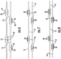
- FIGs. 6-8 address this problem by providing multiple smaller refrigerant pathways 32 in each tube 12 of the plurality of tubes 12.
- two, three, or four pathways 32 may be arranged in each tube 12 to decrease the pressure drop compared to a similar-sized tube 12 with a single pathway while increasing the heat transfer capability of the tube 12 and reducing connections to the header. While it is possible to include more than four pathways 32 in the tube 12, the heat transfer effectiveness of the additional pathways will be decreased since heat conduction from innermost pathways will be limited compared to the outermost pathways.
- louvers 22 may be utilized with these multi-pathway 32 configurations to increase heat transfer and to provide condensate drainage through the web openings 24.
- the heat exchanger 10 may include vortex generators, for example, tabs 34 disposed along the web 14.
- the tabs 34 are oriented across the airflow 20, as shown schematically in FIG. 11 , in order to generate streamwise votices 36 in the airflow 20 as the airflow passes along the web 14.
- the presence of vortices 36 can increase heat transfer between the web 14 and the airflow 20.
- the tabs 34 are triangular in shape, or may be other shapes, for example, trapezoidal, or asymmetrically polygonal, or the like, to generate the desired vortices 36.
- the tabs 34 are disposed in rows 40 extending along a tube length 38, with multiple rows, for example, two or three rows of tabs 34 between adjacent tubes 12.
- the positions of tabs 34 in a first row 40a may be staggered relative to the positions of tabs 34 in a second row 40b, or may be aligned, depending on the vortex 36 desired.
- tabs 34 are aligned such that a tab tip 42 of the tabs 34 faces the same direction, while according to the invention as shown in FIG. 12 , tab tips 42 of tabs 34 or rows of tabs 34 face opposing directions. Further, as shown in FIG. 13 , tabs 34 may be located and oriented to boost a strength of the vortices 36 along the web 14.
- the webs 14 may not be substantially planar, but may be a wave or ruffle shape to further have a desired effect on the airflow 20, such as increased vortex generation.
- the wavy web 14 may be utilized in conjunction with the louvers 22, and/or tabs 34.
Description
- The subject matter disclosed herein relates to heat exchangers. More specifically, the subject disclosure relates to tube and fin configuration for heat exchangers.
US 2005/109496 discloses a heat exchanger having the features of the preamble of claim 1. - Micro-channel heat exchangers have represented the typical construction of heat exchangers for, for example, automotive and heating, ventilation and air conditioning (HVAC) applications, for several years. These heat exchangers are finding wider application in residential and even aerospace HVAC products due to their compactness, relatively low cost, and reduced refrigerant charge when compared to other heat exchanger configurations.
- In micro-channel heat exchangers, liquid or two-phase refrigerant flows through small ports internal to extruded tubes. Air flows through folded fins arranged between the tubes. Due to the high surface density of this construction, and a flat shape of the typical tube, these heat exchangers are prone to moisture and condensate retention and subsequent frost accumulation issues. This is especially problematic when the tubes are arranged horizontally. Water collects on the horizontal surfaces of the tubes, resulting in higher flow and thermal resistance as well as corrosion and pitting of the tube surfaces.
- According to
US 2005/109496 A1 heat exchanger tubing includes at least a pair of tubes that are connected to and separated by a connecting member. The connecting member has a number of fin projections extending at an angle from the member, each fin projection having an opening to allow air to pass through the member. The tubing is arranged between headers of a heat exchanger in an angled configuration so that the fins align with the air flow passing across the tubing for enhanced heat exchange. - A heat exchanger comprising tubes that are connected to and separated by connecting members including projections extending at an angle from the members is also disclosed by
FR 1 524 182 A - According to an aspect of the invention, a heat exchanger comprises: a plurality of tubes to be disposed substantially transverse to a direction of airflow through the heat exchanger and to be arranged in a plurality of tube rows extending substantially along the direction of airflow; a plurality of webs substantially integral to at least two tubes of the plurality of tubes, each web extending between and connected to adjacent tubes of the plurality of tubes; and a plurality of tabs disposed at the plurality of webs substantially transverse to the airflow to generate vortices in the airflow. The plurality of tabs include a first row of tabs, the first row of tabs extending along a tube length between a pair of adjacent tubes of the plurality of tubes, and a second row of tabs, the second row of tabs extending parallel to the first row of tabs between the same pair of adjacent tubes of the plurality of tubes; wherein the tips of the tabs of the first row extend in a common first direction, and wherein the tips of the tabs of the second row extend in a common second direction different than the first direction.
- In further embodiments, the heat exchanger may comprise additionally the following features:
- At least one tube of the plurality of tubes may have an oval or airfoil- shaped cross-section.
- In an embodiment the heat exchanger comprises two or more louvers disposed in two or more louver rows at a web between adjacent tubes of the plurality of tubes.
- In an embodiment the louver has a louver face at an angle to the direction of airflow.
- In an embodiment at least one tube of the plurality of tubes comprises two or more fluid-conveying pathways.
- In an embodiment the number or fluid-conveying pathways of the at least one tube is in the range of two to four.
- In an embodiment the tab is substantially transverse to the airflow to generate vortices in the airflow.
- In an embodiment the plurality of webs form a ruffled or wavy surface.
- In an embodiment the plurality of tubes in a first tube row of the plurality of tube rows are substantially staggered in position relative to the plurality of tubes in an adjacent second tube row of the plurality of tube rows.
- In another embodiment the heat exchanger comprises:
- a plurality of tubes disposed substantially transverse to a direction of airflow through the heat exchanger and arranged in a plurality of tube rows extending substantially along the direction of airflow,
- at least one tube of the plurality of tubes including two or more fluid-conveying pathways; and a plurality of webs substantially integral to two or more tubes of the plurality of tubes, each web extending between and connected to adjacent tubes of the plurality of tubes.
- In an embodiment at least one tube of the plurality of tubes has a cross section with an aspect ratio greater than 1:1, relative to a substantially horizontal web.
- In an embodiment the number or fluid-conveying pathways of the at least one tube is in the range of two to four.
- In an embodiment one or more louvers are disposed in the plurality of webs.
- In an embodiment the one or more louvers have a louver face aligned substantially parallel to the direction of airflow.
- The subject matter, which is regarded as the invention, is particularly pointed out and distinctly claimed in the claims at the conclusion of the specification. The foregoing and other features, and advantages of the invention are apparent from the following detailed description taken in conjunction with the accompanying drawings in which:
-
FIG. 1 is a perspective view of an integral tube and fin heat exchanger not belonging to the invention. -
FIG. 2 is an example not belonging to the invention of an integral tube and fin heat exchanger having elliptical tubes; -
FIG. 3 is an example not belonging to the invention of an integral tube and fin heat exchanger having airfoil- shaped tubes; -
FIG. 4 is an example not belonging to the invention of an integral tube and fin heat exchanger having web louvers; -
FIG. 5 is an example not belonging to the invention of an integral tube and fin heat exchanger having multiple web louvers; -
FIG. 6 is an example not belonging to the invention of an integral tube and fin heat exchanger having multiple fluid pathways per tube; -
FIG. 7 is another example not belonging to the invention of an integral tube and fin heat exchanger having multiple fluid pathways per tube; -
FIG. 8 is yet another example not belonging to the invention of an integral tube and fin heat exchanger having multiple fluid pathways per tube; -
FIG. 9 is still another example not belonging to the invention of an integral tube and fin heat exchanger having multiple fluid pathways per tube; -
FIG. 10 is an example not belonging to the invention of an integral tube and fin heat exchanger including web tabs; -
FIG. 11 is a schematic of vortex flow through an embodiment of an integral tube and fin heat exchanger; -
FIG. 12 is an embodiment of an integral tube and fin heat exchanger including web tabs; -
FIG. 13 is another schematic of vortex flow through an embodiment of an integral tube and fin heat exchanger; and -
FIG. 14 is another example not belonging to the invention of aheat exchanger 10. - The detailed description explains embodiments of the invention, together with advantages and features, by way of example with reference to the drawings.
- Shown in the
FIG. 1 is aheat exchanger 10 structure. In some examples , theheat exchanger 10 is a micro-channel heat exchanger (MCHX). Theheat exchanger 10 has an integrated tube-fin structure where a plurality oftubes 12 are arranged with a plurality ofwebs 14 extending betweenadjacent tubes 12 of the plurality oftubes 12, and acting as fins in this structure. Thewebs 14 are substantially integral to thetubes 12. Arefrigerant flow 16, for example, a liquid or two phase refrigerant, is flowed through the plurality oftubes 12. While the term "refrigerant flow" is utilized throughout the present application, it is to be appreciated that any selected liquid, gas, or two-phase fluid may be flowed through the plurality oftubes 12 for the purposes of heat transfer. In some embodiments, the plurality oftubes 12 are arranged inrows 18. Anairflow 20 flows across the plurality oftubes 12 and the plurality ofwebs 14 such that thermal energy is transferred between theairflow 20 and therefrigerant flow 16 via thetube 12 andweb 14 structure. In some embodiments, a direction of theairflow 20 is substantially perpendicular to therefrigerant flow 16. - Referring now to
FIG. 2 , thetubes 12 have a cross-section that improvesair flow 20 and thus heat transfer between theairflow 20 and theheat exchanger 10. In some embodiments, as shown inFIG. 2 , the cross-section of thetubes 12 are elliptical or may be airfoil shaped as shown inFIG. 3 . Elliptic or airfoil shapes reduce the wake size behind thetubes 12, which decreases pressure drop and improves heat transfer. Referring toFIG. 4 , thewebs 14 include a plurality oflouvers 22 formed in thewebs 14 which extend into theairflow 20. Thelouvers 22 may be formed by, for example, a punching operation which cuts theweb 14 on three sides of thelouver 22 and folds thelouver 22 into position, resulting in aweb opening 24 in theweb 14. In some embodiments, thelouvers 22 each have alouver face 42 which is aligned substantially parallel to theairflow 20. As shown inFIG. 5 , thewebs 14 are configured with multiple rows ofmultiple louvers 22 betweenadjacent tubes 12. Utilizinglouvers 22 andweb openings 24 allows for reduction in material and refrigerant volume compared to a conventional micro-channel heat exchanger and allows for drainage of condensate through theweb openings 24 to reduce condensate/ice buildup and/or corrosion. - In some embodiments, the
webs 14 betweenadjacent tubes 12 are substantially equal in web length 26. It is to be appreciated, however, that the web length 26 may vary as desired. In some embodiments, as also shown inFIG. 2 , thetubes 12 in afirst row 18a oftubes 12 can be offset or staggered relative to an adjacentsecond row 18b oftubes 12 along alength 30 of theheat exchanger 10 to allow for a more compact structure and to increase heat transfer between theairflow 20 and therefrigerant flow 16. - Referring now to
FIG. 6 , it is desired to increase a distance between thetubes 12 or reduce the number oftubes 12 because heat transfer via thewebs 14 is highly effective. Further, reducing a number oftubes 12 reduces necessary connections oftubes 12 to a header (not shown) which distributesrefrigerant flow 16 to thetubes 12. A reduction of the number oftubes 12 alone, however, increases a refrigerant flow pressure drop for the same capacity and flow rates. Further, a reduction of the number oftubes 12 combined with an increase in the cross-sectional area of thetubes 12 to increase flow capacity, results in a reduction in heat transfer due to an increase in a hydraulic diameter of thetubes 12 and a reduction in a total refrigerant side heat transfer area. - The examples of
FIGs. 6-8 address this problem by providing multiple smallerrefrigerant pathways 32 in eachtube 12 of the plurality oftubes 12. As shown inFIGs. 6, 7, and 8 , respectively, two, three, or fourpathways 32 may be arranged in eachtube 12 to decrease the pressure drop compared to a similar-sized tube 12 with a single pathway while increasing the heat transfer capability of thetube 12 and reducing connections to the header. While it is possible to include more than fourpathways 32 in thetube 12, the heat transfer effectiveness of the additional pathways will be decreased since heat conduction from innermost pathways will be limited compared to the outermost pathways. As shown inFIG. 9 ,louvers 22 may be utilized with these multi-pathway 32 configurations to increase heat transfer and to provide condensate drainage through theweb openings 24. - Referring now to
FIG. 10 , theheat exchanger 10 may include vortex generators, for example,tabs 34 disposed along theweb 14. Thetabs 34 are oriented across theairflow 20, as shown schematically inFIG. 11 , in order to generatestreamwise votices 36 in theairflow 20 as the airflow passes along theweb 14. The presence ofvortices 36 can increase heat transfer between theweb 14 and theairflow 20. Referring again toFIG. 10 , thetabs 34 are triangular in shape, or may be other shapes, for example, trapezoidal, or asymmetrically polygonal, or the like, to generate the desiredvortices 36. Thetabs 34 are disposed in rows 40 extending along atube length 38, with multiple rows, for example, two or three rows oftabs 34 betweenadjacent tubes 12. The positions oftabs 34 in afirst row 40a may be staggered relative to the positions oftabs 34 in asecond row 40b, or may be aligned, depending on thevortex 36 desired. - Comparing
FIGs. 10 and12 , it can be seen that in some examples thetabs 34 are aligned such that atab tip 42 of thetabs 34 faces the same direction, while according to the invention as shown inFIG. 12 ,tab tips 42 oftabs 34 or rows oftabs 34 face opposing directions. Further, as shown inFIG. 13 ,tabs 34 may be located and oriented to boost a strength of thevortices 36 along theweb 14. - Referring to
FIG. 14 , in some embodiments, thewebs 14 may not be substantially planar, but may be a wave or ruffle shape to further have a desired effect on theairflow 20, such as increased vortex generation. Thewavy web 14 may be utilized in conjunction with thelouvers 22, and/ortabs 34. - While the invention has been described in detail in connection with only a limited number of embodiments, it should be readily understood that the invention is not limited to such disclosed embodiments. Rather, the invention can be modified to incorporate any number of variations, alterations, substitutions or equivalent arrangements not heretofore described, but which are commensurate with the scope of the invention. Additionally, while various embodiments of the invention have been described, it is to be understood that aspects of the invention may include only some of the described embodiments. Accordingly, the invention is not to be seen as limited by the foregoing description, but is only limited by the scope of the appended claims.
Claims (9)
- A heat exchanger (10) comprising:a plurality of tubes (12) to be disposed substantially transverse to a direction of airflow through the heat exchanger (10) and to be arranged in a plurality of tube (12) rows (40, 40a, 40b) extending substantially along the direction of airflow;a plurality of webs (14) substantially integral to at least two tubes (12) of the plurality of tubes (12), each web (14) extending between and connected to adjacent tubes (12) of the plurality of tubes (12); anda plurality of tabs (34) disposed at the plurality of webs (14) substantially transverse to the airflow to generate vortices in the airflow;wherein the plurality of tabs (34) include a first row of tabs (34), the first row of tabs (34) extending along a tube length (38) between a pair of adjacent tubes (12) of the plurality of tubes (12), and a second row of tabs (34), the second row of tabs (34) extending parallel to the first row of tabs (34) between the same pair of adjacent tubes (12) of the plurality of tubes (12); characterised in that the tips (42) of the tabs (34) of the first row extend in a common first direction, and wherein the tips (42) of the tabs (34) of the second row extend in a common second direction different than the first direction.
- The heat exchanger (10) of Claim 1, wherein the plurality of tabs (34) are substantially triangular or trapezoidal.
- The heat exchanger (10) of Claim 1, wherein at least one tube (12) of the plurality of tubes (12) has a cross section with an aspect ratio greater than 1:1, relative to a substantially horizontal web (14).
- The heat exchanger (10) of Claim 1, wherein at least one tube (12) of the plurality of tubes (12) has an oval or airfoil- shaped cross-section.
- The heat exchanger (10) of Claim 3, wherein at least one tube (12) of the plurality of tubes (12) comprises two or more fluid-conveying pathways.
- The heat exchanger (10) of Claim 4, wherein the number or fluid-conveying pathways of the at least one tube (12) is in the range of two to four.
- The heat exchanger (10) of Claim 1, further comprising one or more louvers (22) disposed in the plurality of webs (14).
- The heat exchanger (10) of Claim 6, further comprising two or more louvers (22) disposed in two or more louver rows at a web (14) between adjacent tubes (12) of the plurality of tubes (12).
- The heat exchanger (10) of Claim 7 or 8, wherein the one or more louvers (22) have a louver face aligned substantially parallel to the direction of airflow.
Applications Claiming Priority (2)
| Application Number | Priority Date | Filing Date | Title |
|---|---|---|---|
| US201161475448P | 2011-04-14 | 2011-04-14 | |
| PCT/US2012/032984 WO2012142070A1 (en) | 2011-04-14 | 2012-04-11 | Heat exchanger |
Publications (2)
| Publication Number | Publication Date |
|---|---|
| EP2697589A1 EP2697589A1 (en) | 2014-02-19 |
| EP2697589B1 true EP2697589B1 (en) | 2020-09-30 |
Family
ID=46022655
Family Applications (1)
| Application Number | Title | Priority Date | Filing Date |
|---|---|---|---|
| EP12717951.3A Active EP2697589B1 (en) | 2011-04-14 | 2012-04-11 | Heat exchanger |
Country Status (5)
| Country | Link |
|---|---|
| US (1) | US20140027098A1 (en) |
| EP (1) | EP2697589B1 (en) |
| CN (1) | CN103477177B (en) |
| ES (1) | ES2834434T3 (en) |
| WO (1) | WO2012142070A1 (en) |
Families Citing this family (21)
| Publication number | Priority date | Publication date | Assignee | Title |
|---|---|---|---|---|
| US20120261104A1 (en) * | 2011-04-12 | 2012-10-18 | Altex Technologies Corporation | Microchannel Heat Exchangers and Reactors |
| WO2013055519A2 (en) * | 2011-10-13 | 2013-04-18 | Carrier Corporation | Heat exchanger |
| KR20150126386A (en) * | 2013-03-01 | 2015-11-11 | 사파 에이에스 | Multi port extrusion (mpe) design |
| WO2016036726A1 (en) * | 2014-09-05 | 2016-03-10 | Carrier Corporation | Multiport extruded heat exchanger |
| WO2017004061A1 (en) * | 2015-06-29 | 2017-01-05 | Carrier Corporation | Microtube heat exchanger |
| US10378835B2 (en) * | 2016-03-25 | 2019-08-13 | Unison Industries, Llc | Heat exchanger with non-orthogonal perforations |
| DE202017104743U1 (en) * | 2016-08-08 | 2017-11-14 | Bundy Refrigeration International Holding B.V. | Heat exchanger with microchannel structure or wing tube structure |
| CN107869930B (en) * | 2016-09-28 | 2020-08-11 | 丹佛斯微通道换热器(嘉兴)有限公司 | Heat exchange assembly for heat exchanger, heat exchanger and mold |
| AT518986B1 (en) * | 2016-10-07 | 2018-03-15 | Dipl Ing Thomas Euler Rolle | heat exchangers |
| FR3057943A1 (en) * | 2016-10-20 | 2018-04-27 | Patrick Ouvry | DEVICE FOR THERMAL ACCUMULATOR WITH ICE HOLD |
| US11262132B2 (en) | 2017-08-03 | 2022-03-01 | Mitsubishi Electric Corporation | Heat exchanger and refrigeration cycle apparatus |
| CN107504854A (en) * | 2017-09-29 | 2017-12-22 | 上海蓝滨石化设备有限责任公司 | A kind of porous surface high flux heat transfer plate pipe and board-like reboiler |
| CN107976101B (en) | 2017-12-22 | 2023-07-14 | 上海发电设备成套设计研究院有限责任公司 | Using method of outer fin heat exchange tube |
| JP7044969B2 (en) * | 2018-03-01 | 2022-03-31 | ダイキン工業株式会社 | Heat exchanger |
| CN108626915A (en) * | 2018-06-22 | 2018-10-09 | 河南科隆集团有限公司 | The parallel-flow evaporator used on refrigerator/freezer |
| WO2020012549A1 (en) * | 2018-07-10 | 2020-01-16 | 三菱電機株式会社 | Heat exchanger, heat exchange device, heat exchanger unit, and refrigeration system |
| WO2020044391A1 (en) * | 2018-08-27 | 2020-03-05 | 三菱電機株式会社 | Heat exchanger, heat exchanger unit, and refrigeration cycle device |
| KR102130086B1 (en) * | 2018-11-29 | 2020-07-06 | 한국생산기술연구원 | Heat Exchanger Having Wing-Shaped Tube |
| US11098962B2 (en) * | 2019-02-22 | 2021-08-24 | Forum Us, Inc. | Finless heat exchanger apparatus and methods |
| DE202019104073U1 (en) * | 2019-07-23 | 2020-10-26 | Bundy Refrigeration Gmbh | Extruded wing tube section, wing tube with extruded wing tube section and heat exchanger with wing tube |
| EP3982074A4 (en) * | 2019-10-08 | 2022-08-10 | Hangzhou Sanhua Research Institute Co., Ltd. | Heat exchanger |
Family Cites Families (17)
| Publication number | Priority date | Publication date | Assignee | Title |
|---|---|---|---|---|
| US3046758A (en) * | 1960-08-11 | 1962-07-31 | Olin Mathieson | Heat exchangers |
| FR1524182A (en) * | 1967-02-24 | 1968-05-10 | Rubanox Soc | Improvements to finned heat exchangers |
| US4817709A (en) * | 1987-12-02 | 1989-04-04 | Carrier Corporation | Ramp wing enhanced plate fin |
| JPH0651758U (en) * | 1990-03-13 | 1994-07-15 | 三星電子株式会社 | Evaporator structure for refrigerator |
| US5647433A (en) * | 1993-12-09 | 1997-07-15 | Sanden Corporation | Heat exchanger |
| JP4451981B2 (en) * | 2000-11-21 | 2010-04-14 | 三菱重工業株式会社 | Heat exchange tube and finless heat exchanger |
| GB0107107D0 (en) * | 2001-03-21 | 2001-05-09 | Dwyer Robert C | Fluid to gas exchangers |
| JP2004125352A (en) * | 2002-10-07 | 2004-04-22 | Denso Corp | Heat exchanger |
| US7007504B2 (en) * | 2003-01-29 | 2006-03-07 | Kyeong-Hwa Kang | Condenser |
| US7028766B2 (en) * | 2003-11-25 | 2006-04-18 | Alcoa Inc. | Heat exchanger tubing with connecting member and fins and methods of heat exchange |
| JP4338667B2 (en) * | 2005-04-01 | 2009-10-07 | カルソニックカンセイ株式会社 | Heat exchanger |
| JP2006322698A (en) * | 2005-04-22 | 2006-11-30 | Denso Corp | Heat exchanger |
| CN1967135A (en) * | 2006-04-21 | 2007-05-23 | 王磊 | Aluminium-made extrusion slender section |
| CN101294779A (en) * | 2008-04-15 | 2008-10-29 | 西安交通大学 | Heat exchange tube fin structure |
| CN101493229A (en) * | 2009-01-15 | 2009-07-29 | 哈尔滨工业大学 | Control method for multiple tail tube pulsating combustor and apparatus |
| CN101493299A (en) * | 2009-01-23 | 2009-07-29 | 江苏双良空调设备股份有限公司 | Wing tube heat exchanger |
| US20110036553A1 (en) * | 2009-08-12 | 2011-02-17 | Brian John Christen | Integral evaporator and defrost heater system |
-
2012
- 2012-04-11 EP EP12717951.3A patent/EP2697589B1/en active Active
- 2012-04-11 CN CN201280018452.1A patent/CN103477177B/en active Active
- 2012-04-11 WO PCT/US2012/032984 patent/WO2012142070A1/en active Application Filing
- 2012-04-11 US US14/111,077 patent/US20140027098A1/en not_active Abandoned
- 2012-04-11 ES ES12717951T patent/ES2834434T3/en active Active
Non-Patent Citations (1)
| Title |
|---|
| None * |
Also Published As
| Publication number | Publication date |
|---|---|
| CN103477177B (en) | 2016-11-16 |
| ES2834434T3 (en) | 2021-06-17 |
| EP2697589A1 (en) | 2014-02-19 |
| CN103477177A (en) | 2013-12-25 |
| WO2012142070A1 (en) | 2012-10-18 |
| US20140027098A1 (en) | 2014-01-30 |
Similar Documents
| Publication | Publication Date | Title |
|---|---|---|
| EP2697589B1 (en) | Heat exchanger | |
| US7913750B2 (en) | Louvered air center with vortex generating extensions for compact heat exchanger | |
| JP6647319B2 (en) | Heat exchanger | |
| US20100263847A1 (en) | Microchannel heat exchanger | |
| US20140231056A1 (en) | Heat exchanger | |
| US20160123681A1 (en) | Fin tube heat exchanger | |
| US10422588B2 (en) | Heat exchanger coil with offset fins | |
| WO2012027098A2 (en) | Microchannel heat exchanger fin | |
| EP3314189B1 (en) | Microtube heat exchanger | |
| JP2005106328A (en) | Heat exchanging device | |
| EP3362759B1 (en) | Heat exchanger for residential hvac applications | |
| EP3608618B1 (en) | Heat exchanger and refrigeration cycle device | |
| US20060266503A1 (en) | Heat transfer fin, heat exchanger, evaporator and condenser for use in car air-conditioner | |
| CN108474629B (en) | Folded conduits for heat exchanger applications | |
| JP2009139085A (en) | Louver type corrugated insert for heat exchanger | |
| US20220128320A1 (en) | Microchannel heat exchanger for a furnace | |
| CN212457513U (en) | Heat exchanger and air conditioner | |
| CN218097370U (en) | Fin for tube-fin heat exchanger and tube-fin heat exchanger | |
| WO2022049886A1 (en) | Corrugated fin-type heat exchanger | |
| US20240060727A1 (en) | Fin device, heat exchanger having the same and method for manufacturing a fin device | |
| CN111928539A (en) | Heat exchanger and air conditioner | |
| WO2016036732A1 (en) | Frost tolerant microchannel heat exchanger for heat pump and refrigeration applications | |
| JP2008286446A (en) | Heat transfer member and heat exchanger using the same | |
| KR20110080899A (en) | Fin for heat exchanger | |
| KR20110090522A (en) | Fin for heat exchanger |
Legal Events
| Date | Code | Title | Description |
|---|---|---|---|
| PUAI | Public reference made under article 153(3) epc to a published international application that has entered the european phase |
Free format text: ORIGINAL CODE: 0009012 |
|
| 17P | Request for examination filed |
Effective date: 20131015 |
|
| AK | Designated contracting states |
Kind code of ref document: A1 Designated state(s): AL AT BE BG CH CY CZ DE DK EE ES FI FR GB GR HR HU IE IS IT LI LT LU LV MC MK MT NL NO PL PT RO RS SE SI SK SM TR |
|
| RIN1 | Information on inventor provided before grant (corrected) |
Inventor name: YAZDANI, MIAD Inventor name: WHITON, JOHN H. Inventor name: MUNOZ, JULES R. Inventor name: ALAHYARI, ABBAS A. |
|
| DAX | Request for extension of the european patent (deleted) | ||
| STAA | Information on the status of an ep patent application or granted ep patent |
Free format text: STATUS: EXAMINATION IS IN PROGRESS |
|
| 17Q | First examination report despatched |
Effective date: 20190916 |
|
| GRAP | Despatch of communication of intention to grant a patent |
Free format text: ORIGINAL CODE: EPIDOSNIGR1 |
|
| STAA | Information on the status of an ep patent application or granted ep patent |
Free format text: STATUS: GRANT OF PATENT IS INTENDED |
|
| INTG | Intention to grant announced |
Effective date: 20200515 |
|
| GRAS | Grant fee paid |
Free format text: ORIGINAL CODE: EPIDOSNIGR3 |
|
| GRAA | (expected) grant |
Free format text: ORIGINAL CODE: 0009210 |
|
| STAA | Information on the status of an ep patent application or granted ep patent |
Free format text: STATUS: THE PATENT HAS BEEN GRANTED |
|
| AK | Designated contracting states |
Kind code of ref document: B1 Designated state(s): AL AT BE BG CH CY CZ DE DK EE ES FI FR GB GR HR HU IE IS IT LI LT LU LV MC MK MT NL NO PL PT RO RS SE SI SK SM TR |
|
| REG | Reference to a national code |
Ref country code: CH Ref legal event code: EP Ref country code: GB Ref legal event code: FG4D |
|
| REG | Reference to a national code |
Ref country code: AT Ref legal event code: REF Ref document number: 1319235 Country of ref document: AT Kind code of ref document: T Effective date: 20201015 |
|
| REG | Reference to a national code |
Ref country code: DE Ref legal event code: R096 Ref document number: 602012072554 Country of ref document: DE |
|
| REG | Reference to a national code |
Ref country code: IE Ref legal event code: FG4D |
|
| PG25 | Lapsed in a contracting state [announced via postgrant information from national office to epo] |
Ref country code: BG Free format text: LAPSE BECAUSE OF FAILURE TO SUBMIT A TRANSLATION OF THE DESCRIPTION OR TO PAY THE FEE WITHIN THE PRESCRIBED TIME-LIMIT Effective date: 20201230 Ref country code: SE Free format text: LAPSE BECAUSE OF FAILURE TO SUBMIT A TRANSLATION OF THE DESCRIPTION OR TO PAY THE FEE WITHIN THE PRESCRIBED TIME-LIMIT Effective date: 20200930 Ref country code: NO Free format text: LAPSE BECAUSE OF FAILURE TO SUBMIT A TRANSLATION OF THE DESCRIPTION OR TO PAY THE FEE WITHIN THE PRESCRIBED TIME-LIMIT Effective date: 20201230 Ref country code: HR Free format text: LAPSE BECAUSE OF FAILURE TO SUBMIT A TRANSLATION OF THE DESCRIPTION OR TO PAY THE FEE WITHIN THE PRESCRIBED TIME-LIMIT Effective date: 20200930 Ref country code: GR Free format text: LAPSE BECAUSE OF FAILURE TO SUBMIT A TRANSLATION OF THE DESCRIPTION OR TO PAY THE FEE WITHIN THE PRESCRIBED TIME-LIMIT Effective date: 20201231 Ref country code: FI Free format text: LAPSE BECAUSE OF FAILURE TO SUBMIT A TRANSLATION OF THE DESCRIPTION OR TO PAY THE FEE WITHIN THE PRESCRIBED TIME-LIMIT Effective date: 20200930 |
|
| REG | Reference to a national code |
Ref country code: AT Ref legal event code: MK05 Ref document number: 1319235 Country of ref document: AT Kind code of ref document: T Effective date: 20200930 |
|
| PG25 | Lapsed in a contracting state [announced via postgrant information from national office to epo] |
Ref country code: LV Free format text: LAPSE BECAUSE OF FAILURE TO SUBMIT A TRANSLATION OF THE DESCRIPTION OR TO PAY THE FEE WITHIN THE PRESCRIBED TIME-LIMIT Effective date: 20200930 Ref country code: RS Free format text: LAPSE BECAUSE OF FAILURE TO SUBMIT A TRANSLATION OF THE DESCRIPTION OR TO PAY THE FEE WITHIN THE PRESCRIBED TIME-LIMIT Effective date: 20200930 |
|
| REG | Reference to a national code |
Ref country code: NL Ref legal event code: MP Effective date: 20200930 |
|
| REG | Reference to a national code |
Ref country code: LT Ref legal event code: MG4D |
|
| PG25 | Lapsed in a contracting state [announced via postgrant information from national office to epo] |
Ref country code: EE Free format text: LAPSE BECAUSE OF FAILURE TO SUBMIT A TRANSLATION OF THE DESCRIPTION OR TO PAY THE FEE WITHIN THE PRESCRIBED TIME-LIMIT Effective date: 20200930 Ref country code: CZ Free format text: LAPSE BECAUSE OF FAILURE TO SUBMIT A TRANSLATION OF THE DESCRIPTION OR TO PAY THE FEE WITHIN THE PRESCRIBED TIME-LIMIT Effective date: 20200930 Ref country code: LT Free format text: LAPSE BECAUSE OF FAILURE TO SUBMIT A TRANSLATION OF THE DESCRIPTION OR TO PAY THE FEE WITHIN THE PRESCRIBED TIME-LIMIT Effective date: 20200930 Ref country code: NL Free format text: LAPSE BECAUSE OF FAILURE TO SUBMIT A TRANSLATION OF THE DESCRIPTION OR TO PAY THE FEE WITHIN THE PRESCRIBED TIME-LIMIT Effective date: 20200930 Ref country code: PT Free format text: LAPSE BECAUSE OF FAILURE TO SUBMIT A TRANSLATION OF THE DESCRIPTION OR TO PAY THE FEE WITHIN THE PRESCRIBED TIME-LIMIT Effective date: 20210201 Ref country code: RO Free format text: LAPSE BECAUSE OF FAILURE TO SUBMIT A TRANSLATION OF THE DESCRIPTION OR TO PAY THE FEE WITHIN THE PRESCRIBED TIME-LIMIT Effective date: 20200930 Ref country code: SM Free format text: LAPSE BECAUSE OF FAILURE TO SUBMIT A TRANSLATION OF THE DESCRIPTION OR TO PAY THE FEE WITHIN THE PRESCRIBED TIME-LIMIT Effective date: 20200930 |
|
| PG25 | Lapsed in a contracting state [announced via postgrant information from national office to epo] |
Ref country code: AT Free format text: LAPSE BECAUSE OF FAILURE TO SUBMIT A TRANSLATION OF THE DESCRIPTION OR TO PAY THE FEE WITHIN THE PRESCRIBED TIME-LIMIT Effective date: 20200930 Ref country code: AL Free format text: LAPSE BECAUSE OF FAILURE TO SUBMIT A TRANSLATION OF THE DESCRIPTION OR TO PAY THE FEE WITHIN THE PRESCRIBED TIME-LIMIT Effective date: 20200930 Ref country code: PL Free format text: LAPSE BECAUSE OF FAILURE TO SUBMIT A TRANSLATION OF THE DESCRIPTION OR TO PAY THE FEE WITHIN THE PRESCRIBED TIME-LIMIT Effective date: 20200930 Ref country code: IS Free format text: LAPSE BECAUSE OF FAILURE TO SUBMIT A TRANSLATION OF THE DESCRIPTION OR TO PAY THE FEE WITHIN THE PRESCRIBED TIME-LIMIT Effective date: 20210130 |
|
| REG | Reference to a national code |
Ref country code: ES Ref legal event code: FG2A Ref document number: 2834434 Country of ref document: ES Kind code of ref document: T3 Effective date: 20210617 |
|
| PG25 | Lapsed in a contracting state [announced via postgrant information from national office to epo] |
Ref country code: SK Free format text: LAPSE BECAUSE OF FAILURE TO SUBMIT A TRANSLATION OF THE DESCRIPTION OR TO PAY THE FEE WITHIN THE PRESCRIBED TIME-LIMIT Effective date: 20200930 |
|
| REG | Reference to a national code |
Ref country code: DE Ref legal event code: R097 Ref document number: 602012072554 Country of ref document: DE |
|
| PLBE | No opposition filed within time limit |
Free format text: ORIGINAL CODE: 0009261 |
|
| STAA | Information on the status of an ep patent application or granted ep patent |
Free format text: STATUS: NO OPPOSITION FILED WITHIN TIME LIMIT |
|
| PG25 | Lapsed in a contracting state [announced via postgrant information from national office to epo] |
Ref country code: DK Free format text: LAPSE BECAUSE OF FAILURE TO SUBMIT A TRANSLATION OF THE DESCRIPTION OR TO PAY THE FEE WITHIN THE PRESCRIBED TIME-LIMIT Effective date: 20200930 |
|
| 26N | No opposition filed |
Effective date: 20210701 |
|
| PG25 | Lapsed in a contracting state [announced via postgrant information from national office to epo] |
Ref country code: IT Free format text: LAPSE BECAUSE OF FAILURE TO SUBMIT A TRANSLATION OF THE DESCRIPTION OR TO PAY THE FEE WITHIN THE PRESCRIBED TIME-LIMIT Effective date: 20200930 |
|
| REG | Reference to a national code |
Ref country code: DE Ref legal event code: R119 Ref document number: 602012072554 Country of ref document: DE |
|
| PG25 | Lapsed in a contracting state [announced via postgrant information from national office to epo] |
Ref country code: SI Free format text: LAPSE BECAUSE OF FAILURE TO SUBMIT A TRANSLATION OF THE DESCRIPTION OR TO PAY THE FEE WITHIN THE PRESCRIBED TIME-LIMIT Effective date: 20200930 Ref country code: MC Free format text: LAPSE BECAUSE OF FAILURE TO SUBMIT A TRANSLATION OF THE DESCRIPTION OR TO PAY THE FEE WITHIN THE PRESCRIBED TIME-LIMIT Effective date: 20200930 |
|
| GBPC | Gb: european patent ceased through non-payment of renewal fee |
Effective date: 20210411 |
|
| PG25 | Lapsed in a contracting state [announced via postgrant information from national office to epo] |
Ref country code: LU Free format text: LAPSE BECAUSE OF NON-PAYMENT OF DUE FEES Effective date: 20210411 |
|
| REG | Reference to a national code |
Ref country code: BE Ref legal event code: MM Effective date: 20210430 |
|
| PG25 | Lapsed in a contracting state [announced via postgrant information from national office to epo] |
Ref country code: GB Free format text: LAPSE BECAUSE OF NON-PAYMENT OF DUE FEES Effective date: 20210411 Ref country code: DE Free format text: LAPSE BECAUSE OF NON-PAYMENT OF DUE FEES Effective date: 20211103 Ref country code: CH Free format text: LAPSE BECAUSE OF NON-PAYMENT OF DUE FEES Effective date: 20210430 Ref country code: LI Free format text: LAPSE BECAUSE OF NON-PAYMENT OF DUE FEES Effective date: 20210430 |
|
| PG25 | Lapsed in a contracting state [announced via postgrant information from national office to epo] |
Ref country code: IE Free format text: LAPSE BECAUSE OF NON-PAYMENT OF DUE FEES Effective date: 20210411 |
|
| PG25 | Lapsed in a contracting state [announced via postgrant information from national office to epo] |
Ref country code: IS Free format text: LAPSE BECAUSE OF FAILURE TO SUBMIT A TRANSLATION OF THE DESCRIPTION OR TO PAY THE FEE WITHIN THE PRESCRIBED TIME-LIMIT Effective date: 20210130 |
|
| PG25 | Lapsed in a contracting state [announced via postgrant information from national office to epo] |
Ref country code: BE Free format text: LAPSE BECAUSE OF NON-PAYMENT OF DUE FEES Effective date: 20210430 |
|
| PGFP | Annual fee paid to national office [announced via postgrant information from national office to epo] |
Ref country code: FR Payment date: 20230321 Year of fee payment: 12 |
|
| PG25 | Lapsed in a contracting state [announced via postgrant information from national office to epo] |
Ref country code: HU Free format text: LAPSE BECAUSE OF FAILURE TO SUBMIT A TRANSLATION OF THE DESCRIPTION OR TO PAY THE FEE WITHIN THE PRESCRIBED TIME-LIMIT; INVALID AB INITIO Effective date: 20120411 Ref country code: CY Free format text: LAPSE BECAUSE OF FAILURE TO SUBMIT A TRANSLATION OF THE DESCRIPTION OR TO PAY THE FEE WITHIN THE PRESCRIBED TIME-LIMIT Effective date: 20200930 |
|
| PGFP | Annual fee paid to national office [announced via postgrant information from national office to epo] |
Ref country code: ES Payment date: 20230502 Year of fee payment: 12 |