EP2697587B1 - Verfahren zum betrieb eines elektrolichtbogenofens - Google Patents
Verfahren zum betrieb eines elektrolichtbogenofens Download PDFInfo
- Publication number
- EP2697587B1 EP2697587B1 EP12711347.0A EP12711347A EP2697587B1 EP 2697587 B1 EP2697587 B1 EP 2697587B1 EP 12711347 A EP12711347 A EP 12711347A EP 2697587 B1 EP2697587 B1 EP 2697587B1
- Authority
- EP
- European Patent Office
- Prior art keywords
- oxygen
- furnace
- containing gas
- input element
- input
- Prior art date
- Legal status (The legal status is an assumption and is not a legal conclusion. Google has not performed a legal analysis and makes no representation as to the accuracy of the status listed.)
- Active
Links
Images


Classifications
-
- F—MECHANICAL ENGINEERING; LIGHTING; HEATING; WEAPONS; BLASTING
- F27—FURNACES; KILNS; OVENS; RETORTS
- F27B—FURNACES, KILNS, OVENS OR RETORTS IN GENERAL; OPEN SINTERING OR LIKE APPARATUS
- F27B3/00—Hearth-type furnaces, e.g. of reverberatory type; Electric arc furnaces ; Tank furnaces
- F27B3/10—Details, accessories or equipment, e.g. dust-collectors, specially adapted for hearth-type furnaces
- F27B3/22—Arrangements of air or gas supply devices
- F27B3/225—Oxygen blowing
-
- C—CHEMISTRY; METALLURGY
- C21—METALLURGY OF IRON
- C21C—PROCESSING OF PIG-IRON, e.g. REFINING, MANUFACTURE OF WROUGHT-IRON OR STEEL; TREATMENT IN MOLTEN STATE OF FERROUS ALLOYS
- C21C5/00—Manufacture of carbon-steel, e.g. plain mild steel, medium carbon steel or cast steel or stainless steel
- C21C5/52—Manufacture of steel in electric furnaces
- C21C5/5211—Manufacture of steel in electric furnaces in an alternating current [AC] electric arc furnace
- C21C5/5217—Manufacture of steel in electric furnaces in an alternating current [AC] electric arc furnace equipped with burners or devices for injecting gas, i.e. oxygen, or pulverulent materials into the furnace
-
- C—CHEMISTRY; METALLURGY
- C21—METALLURGY OF IRON
- C21C—PROCESSING OF PIG-IRON, e.g. REFINING, MANUFACTURE OF WROUGHT-IRON OR STEEL; TREATMENT IN MOLTEN STATE OF FERROUS ALLOYS
- C21C7/00—Treating molten ferrous alloys, e.g. steel, not covered by groups C21C1/00 - C21C5/00
- C21C7/04—Removing impurities by adding a treating agent
- C21C7/072—Treatment with gases
-
- F—MECHANICAL ENGINEERING; LIGHTING; HEATING; WEAPONS; BLASTING
- F27—FURNACES; KILNS; OVENS; RETORTS
- F27D—DETAILS OR ACCESSORIES OF FURNACES, KILNS, OVENS OR RETORTS, IN SO FAR AS THEY ARE OF KINDS OCCURRING IN MORE THAN ONE KIND OF FURNACE
- F27D13/00—Apparatus for preheating charges; Arrangements for preheating charges
- F27D13/002—Preheating scrap
-
- F—MECHANICAL ENGINEERING; LIGHTING; HEATING; WEAPONS; BLASTING
- F27—FURNACES; KILNS; OVENS; RETORTS
- F27D—DETAILS OR ACCESSORIES OF FURNACES, KILNS, OVENS OR RETORTS, IN SO FAR AS THEY ARE OF KINDS OCCURRING IN MORE THAN ONE KIND OF FURNACE
- F27D17/00—Arrangements for using waste heat; Arrangements for using, or disposing of, waste gases
- F27D17/20—Arrangements for treatment or cleaning of waste gases
- F27D17/22—Arrangements for treatment or cleaning of waste gases for removing solid constituents
-
- C—CHEMISTRY; METALLURGY
- C21—METALLURGY OF IRON
- C21C—PROCESSING OF PIG-IRON, e.g. REFINING, MANUFACTURE OF WROUGHT-IRON OR STEEL; TREATMENT IN MOLTEN STATE OF FERROUS ALLOYS
- C21C5/00—Manufacture of carbon-steel, e.g. plain mild steel, medium carbon steel or cast steel or stainless steel
- C21C5/52—Manufacture of steel in electric furnaces
- C21C5/5211—Manufacture of steel in electric furnaces in an alternating current [AC] electric arc furnace
- C21C2005/5223—Manufacture of steel in electric furnaces in an alternating current [AC] electric arc furnace with post-combustion
-
- Y—GENERAL TAGGING OF NEW TECHNOLOGICAL DEVELOPMENTS; GENERAL TAGGING OF CROSS-SECTIONAL TECHNOLOGIES SPANNING OVER SEVERAL SECTIONS OF THE IPC; TECHNICAL SUBJECTS COVERED BY FORMER USPC CROSS-REFERENCE ART COLLECTIONS [XRACs] AND DIGESTS
- Y02—TECHNOLOGIES OR APPLICATIONS FOR MITIGATION OR ADAPTATION AGAINST CLIMATE CHANGE
- Y02P—CLIMATE CHANGE MITIGATION TECHNOLOGIES IN THE PRODUCTION OR PROCESSING OF GOODS
- Y02P10/00—Technologies related to metal processing
- Y02P10/20—Recycling
Definitions
- the invention relates to a method for operating an electric arc furnace, in which located in a bottom vessel molten material, in particular steel, is heated with at least one arc, wherein on the bottom vessel a lid is arranged, wherein at least one point of the electric arc furnace, an outlet opening is arranged from which kiln exhaust gases are led out of the interior of the kiln and fed to a dedusting plant and wherein an oxygen-containing gas is introduced into the interior of the kiln for afterburning.
- Electric arc furnaces of this type and methods for their operation are well known in the art.
- the electric arc furnace can be designed as a direct current furnace with a melting electrode and a bottom electrode or as an alternating current furnace with three melting electrodes.
- An electrode regulator serves to maintain a defined arc length.
- the furnace vessel comprises a masonry or tamped bottom vessel made of refractory material, as well as a top vessel provided with cooling elements and a pivotable lid.
- auxiliary burners are often provided (operation with natural gas and oxygen). With swung lid can Scrap and additives are charged into the oven.
- the tapping of the molten steel is done in a pan.
- the slag can be drained into a slag bucket.
- a relevant topic here is a targeted post-combustion using oxygen-containing gas or oxygen, with which the scrap bed can be preheated or melted. It is known to initiate the afterburning at suitable locations of the furnace, the oxygen-containing gas into the furnace interior.
- the EP 0 834 049 B1 discloses for this purpose to inject oxygen-containing gas at high speed and into the interior of the oven in such a way that the gas is in rotation.
- relatively high nozzle exit speeds between 50 m / s and 125 m / s are desired.
- the invention is therefore based on the object, a method of the type mentioned in such a way that an improved afterburning is reached in the oven. In this case, an optimal use of the introduced gas should be achieved.
- the solution of this problem by the invention is characterized in that the introduction of the oxygen-containing gas takes place at an inlet opening which is spaced from the outlet opening, wherein the oxygen-containing gas is flowed into the oven interior by means of at least one input element, wherein the at least one input element radially aligned in the wall of the bottom vessel is arranged or wherein the at least one input element to the furnace center aligned in the wall of the bottom vessel is arranged, wherein the exit direction of the input element to the horizontal angle between 5 ° and 15 ° downwardly includes, wherein the oxygen-containing gas so via which at least one input element is allowed to flow into the interior of the oven, that it has a flow velocity of less than 5 m / s, wherein the oxygen-containing gas is fed via a feed line to the at least one input element and the gas in de r supply line immediately before reaching the input element, an overpressure against the pressure in the electric arc furnace of a maximum of 0.5 bar, preferably of at most 0.25 bar, having.
- the outlet opening is usually arranged in the lid, wherein the bottom vessel and the lid may have a substantially round basic shape and wherein the outlet opening and the inlet opening preferably lie diagonally opposite one another. It is particularly preferred that in addition to the input of oxygen-containing gas at the inlet opening arranged diagonally from the outlet opening no input of oxygen-containing gas at a speed over 5 m / s takes place; it So no entry of oxygen-containing gas at high speed (jet function of the burner).
- the bottom vessel is preferably designed for receiving molten material up to a maximum level, wherein the inlet opening is arranged as deep as possible, but without the risk of clogging with liquid or doughy material.
- the inlet opening is in a range between 20 and 150 cm above the maximum level height.
- the oxygen-containing gas can also be input via a plurality of input elements, which are arranged horizontally next to one another and / or in vertical direction one above the other. Depending on the size of the furnace can therefore also be provided that the input elements are arranged one above the other. All input elements can be arranged on the circumference of the wall horizontally next to each other or in several levels one above the other. In any case, it must be ensured that the input elements extend over a maximum of 75% of the oven circumference, which are farthest from the discharge opening to the dedusting system. Otherwise, there is a risk that input oxygen is sucked unused into the exhaust system.
- the at least one input element preferably has a funnel-shaped broadening in its exit end region.
- the entered oxygen-containing gas which may also be technically pure oxygen, introduced quasi-pressure in the scrap bulk ("breathed") is.
- the distribution of the gas is not carried out by an initially discontinued at the nozzle exit exit velocity, but by the passage in the furnace interior, which takes place through the deduction of the furnace gas through the cover hole.
- the oxygen-containing gas is supplied in the supply line, for example, with a factory line pressure of 14 bar.
- the invention provides that the oxygen immediately relaxes on leaving the input element in the furnace interior, d. H. is essentially depressurized.
- a strong increase in the velocity of the gas takes place when leaving the nozzle.
- the aim is for the oxygen to be supplied in such a way that it comes to rest as much as possible.
- the production of the draft is due to the primary dedusting
- the input elements are positioned as low as possible, with due consideration being given to the oven wall (which is generally known to the oven operator). The aim is then, even at low Ofenhellgraden, the post-combustion take place in the scrap pile.
- the input elements which act as diffusers, above burners, because there are normally no caking there.
- the primary dedusting system attracts the flue gases. This then also the post-combustion oxygen with the existing carbon monoxide and the hydrogen in combination and thus reacted.
- an electric arc furnace 1 is schematically outlined. This has a masonry bottom vessel 2, in which molten material 3, in particular in the form of steel, can be recorded (covered by a slag layer). A lid 5 covers the bottom vessel 2. Three electrodes 14 arranged in the cover 5 are arranged above the level of the molten material 3. In a known manner, an arc 4 is generated by establishing a potential between the electrodes 14 and material 3, which causes the melting process of the material 3.
- an outlet opening for the furnace gas which is passed from here to a dedusting system 8.
- oxygen-containing gas G which may be technically pure oxygen
- outlet opening 7 and the inlet opening 9 are virtually diagonal in Furnace arranged, ie they have the maximum possible distance from each other (if one assumes the outlet opening 7 as given).
- FIG. 3 shows that the oxygen-containing gas G is brought into the furnace interior by means of at least one input element 11 in the form of a diffuser.
- the diffuser has - in contrast to a gas nozzle - in its end a funnel-shaped widening 13, so that the exiting gas is not accelerated, but is slowed down.
- the aim is namely that the gas leaves the input element 11 in the exit direction S with the lowest possible outflow velocity v.
- the outlet direction S of the input element 11 is aligned towards the middle of the furnace, so that the gas enters the interior of the furnace without twisting.
- the outlet direction S can be radially aligned; however, it is shown that the outlet direction S points downward at a small angle ⁇ (preferably between 5 ° and 15 °) relative to the horizontal.
- the at least one input element 11 is arranged as deep as possible in the bottom vessel 2.
- the bottom vessel 2 is designed to receive molten material 3 up to a maximum level height of h.
- the at least one input element 11 is arranged in a height range ⁇ h over h. This additional height ⁇ h is to be chosen as small as possible and depends on the degree of fermentation that is to be expected.
- the input element 11 is supported by a holder 15, which is welded to the wall 10 of the bottom vessel 2, in particular to the outer panel of the wall 10th
- the oxygen-containing gas G is supplied to the input element 11.
- the funnel-shaped widening 13 ensures a low outflow velocity v of the gas G into the interior of the oven.
- All input elements 11 can be supplied via a feed line 12 with gas G.
Landscapes
- Engineering & Computer Science (AREA)
- Mechanical Engineering (AREA)
- General Engineering & Computer Science (AREA)
- Chemical & Material Sciences (AREA)
- Environmental & Geological Engineering (AREA)
- Materials Engineering (AREA)
- Metallurgy (AREA)
- Organic Chemistry (AREA)
- Manufacturing & Machinery (AREA)
- Vertical, Hearth, Or Arc Furnaces (AREA)
Description
- Die Erfindung betrifft ein Verfahren zum Betrieb eines Elektrolichtbogenofens, bei dem sich in einem Bodengefäß befindliches schmelzflüssiges Material, insbesondere Stahl, mit mindestens einem Lichtbogen erhitzt wird, wobei auf dem Bodengefäß ein Deckel angeordnet ist, wobei an zumindest einer Stelle des Elektrolichtbogenofens eine Austrittsöffnung angeordnet ist, von der aus Ofenabgase aus dem Ofeninneren heraus geleitet und einer Entstaubungsanlage zugeführt werden und wobei zur Nachverbrennung ein sauerstoffhaltiges Gas in das Ofeninnere eingeleitet wird.
- Elektrolichtbogenöfen dieser Art sowie Verfahren zu deren Betrieb sind im Stand der Technik hinlänglich bekannt. Der Lichtbogenofen kann als Gleichstromofen mit einer Schmelzeelektrode und einer Bodenelektrode oder als Wechselstromofen mit drei Schmelzeelektroden ausgeführt sein. Zur Einhaltung einer definierten Lichtbogenlänge dient ein Elektrodenregler. Das Ofengefäß umfasst ein gemauertes oder gestampftes Bodengefäß aus Feuerfestmaterial, sowie ein mit Kühlelementen versehenes Obergefäß und einen schwenkbaren Deckel. Im Obergefäß sind häufig Hilfsbrenner (Betrieb mit Erdgas und Sauerstoff) vorgesehen. Bei aufgeschwenktem Deckel können Schrott und Zusatzstoffe in den Ofen chargiert werden. Der Abstich des geschmolzenen Stahls erfolgt in eine Pfanne. Die Schlacke kann in einen Schlackenkübel abgelassen werden.
- Beim Betrieb des Lichtbogenofens sind verschiedene Problemkreise zu beachten, um eine qualitativ hochwertige Stahlverarbeitung sicherzustellen sowie eine kostengünstige Produktion zu ermöglichen.
- Ein hierbei relevantes Thema ist eine gezielte Nachverbrennung unter Einsatz von sauerstoffhaltigem Gas bzw. Sauerstoff, womit die Schrottschüttung vorgewärmt bzw. geschmolzen werden kann. Dabei ist es bekannt, zur Nachverbrennung an geeigneten Stellen des Ofens das sauerstoffhaltige Gas in das Ofeninnere einzuleiten.
- Die
EP 0 834 049 B1 offenbart hierzu, sauerstoffhaltiges Gas mit hoher Geschwindigkeit und so in das Ofeninnere einzudüsen, dass sich das Gas in Rotation befindet. Hierbei werden relativ hohe Düsenaustrittsgeschwindigkeiten zwischen 50 m/s und 125 m/s angestrebt. - In der
DE 25 41 086 A1 wird Luft unkontrolliert ins Innere eines Elektrolichtbogenofens eingesaugt. Im Ofeninneren selbst wird hierzu ein Unterdruck aufrecht erhalten. - Es hat sich erwiesen, dass der Nachverbrennungseffekt insbesondere unter dem Gesichtspunkt der Vorwärmung bzw. der Aufschmelzung des Schrotts noch nicht optimal ist.
- Der Erfindung liegt daher die Aufgabe zugrunde, ein Verfahren der eingangs genannten Art so fortzubilden, dass eine verbesserte Nachverbrennung im Ofen erreicht wird. Dabei soll eine optimale Nutzung des eingebrachten Gases erreicht werden.
- Die Lösung dieser Aufgabe durch die Erfindung ist dadurch gekennzeichnet, dass die Einleitung des sauerstoffhaltigen Gases an einer Eintrittsöffnung erfolgt, die von der Austrittsöffnung beabstandet ist, wobei das sauerstoffhaltige Gas mittels mindestens eines Eingabeelements in das Ofeninnere einströmen gelassen wird, wobei das mindestens eine Eingabeelement radial ausgerichtet in der Wandung des Bodengefäßes angeordnet ist oder wobei das mindestens eine Eingabeelement zur Ofenmitte hin ausgerichtet in der Wandung des Bodengefäßes angeordnet ist, wobei die Austrittsrichtung des Eingabeelements zur Horizontalen einen Winkel zwischen 5° und 15° nach unten einschließt, wobei das sauerstoffhaltige Gas so über das mindestens eine Eingabeelement in das Ofeninnere einströmen gelassen wird, dass es eine Ausströmgeschwindigkeit von weniger als 5 m/s aufweist, wobei das sauerstoffhaltige Gas über eine Zuleitung dem mindestens einen Eingabeelement zugeführt wird und das Gas in der Zuleitung unmittelbar vor dem Erreichen des Eingabeelements einen Überdruck gegenüber dem Druck im Elektrolichtbogenofen von maximal 0,5 bar, vorzugsweise von maximal 0,25 bar, aufweist.
- Die Austrittsöffnung ist zumeist im Deckel angeordnet, wobei das Bodengefäß und der Deckel eine im wesentlichen runde Grundform haben können und wobei sich die Austrittsöffnung und die Eintrittsöffnung bevorzugt diagonal gegenüberliegen. Besonders bevorzugt ist vorgesehen, dass neben der Eingabe von sauerstoffhaltigem Gas an der diagonal von der Austrittsöffnung angeordneten Eintrittsöffnung keine Eingabe von sauerstoffhaltigem Gas mit einer Geschwindigkeit über 5 m/s erfolgt; es erfolgt also keine Eingabe von sauerstoffhaltigem Gas mit hoher Geschwindigkeit (Jet-Funktion der Brenner).
- Das Bodengefäß ist bevorzugt zur Aufnahme von schmelzflüssigem Material bis zu einer maximalen Pegelhöhe ausgebildet, wobei die Eintrittsöffnung möglichst tief, aber ohne die Gefahr, mit flüssigem oder teigigem Material zu verstopften, angeordnet ist. Besonders bevorzugt liegt die Eintrittsöffnung in einem Bereich zwischen 20 und 150 cm oberhalb der maximalen Pegelhöhe.
- Das sauerstoffhaltige Gas kann auch über mehrere Eingabeelemente eingegeben werden, die parallel horizontal nebeneinander und/oder in vertikale Richtung übereinander angeordnet sind. In Abhängigkeit der Größe des Ofens kann also auch vorgesehen werden, dass die Eingabeelemente übereinander angeordnet sind. Alle Eingabeelemente können am Umfang der Wandung horizontal nebeneinander oder auch in mehreren Ebene übereinander angeordnet sein. In jedem Falle muss sichergestellt sein, dass die Eingabeelemente sich über maximal die 75 % des Ofenumfangs erstrecken, die am weitesten von der Austrittsöffnung zur Entstaubungsanlage entfernt sind. Ansonsten besteht die Gefahr, dass eingegebener Sauerstoff ungenutzt in die Abgasstrecke gesaugt wird.
- Das mindestens eine Eingabeelement weist bevorzugt in seinem Austrittsendbereich eine trichterförmige Verbreiterung auf.
- Mit der vorgeschlagenen Vorgehensweise wird erreicht, dass das eingegebene sauerstoffhaltige Gas, bei dem es sich auch um technisch reinen Sauerstoff handeln kann, quasi drucklos in die Schrottschüttung eingebracht ("gehaucht") wird. Die Verteilung des Gases erfolgt nicht durch eine anfänglich beim Düsenaustritt aufgegebenen Austrittsgeschwindigkeit, sondern durch den Durchzug im Ofeninneren, der durch den Abzug des Ofengases durch das Deckelloch erfolgt.
- Das sauerstoffhaltige Gas wird in der zuführenden Leitung beispielsweise mit einem Werkleitungs-Druck von 14 bar zugeführt. Indes sieht die Erfindung vor, dass sich der Sauerstoff beim Verlassen des Eingabeelements im Ofeninneren sofort entspannt, d. h. im wesentlichen drucklos wird. Im Stand der Technik wird indes vorgesehen, dass über Düsen oder Injektoren ein starker Geschwindigkeitsanstieg des Gases beim Verlassen der Düse erfolgt. Es wird also letztlich angestrebt, dass der Sauerstoff so zugeführt wird, dass er möglichst zur Ruhe kommt. Die Erzeugung des Durchzuges erfolgt aufgrund der Primärentstaubung
- Möglich ist eine vorteilhafte Betriebsweise, bei der im Falle dessen, dass keine Nachverbrennung gewünscht wird, durch die Eingabeelemente Pressluft geleitet wird, um die Eingabeelemente freizuhalten.
- Die Eingabeelemente werden erfindungsgemäß so tief wie möglich positioniert, wobei Verbärungen an der Ofenwand entsprechend zu berücksichtigen sind (die dem Ofenbetreiber in der Regel bekannt sind). Ziel ist es dabei, dann auch bei niedrigen Ofenfüllgraden, die Nachverbrennung in der Schrottschüttung stattfinden zu lassen. Eine Möglichkeit ist es auch, die Eingabeelemente, die als Diffusoren wirken, oberhalb von Brennern anzuordnen, weil dort im Normalfall keine Anbackungen sind.
- Die Primärentstaubung zieht die Rauchgase an. Damit wird dann auch der Nachverbrennungs-Sauerstoff mit dem vorhandenen Kohlenmonoxid und dem Wasserstoff in Verbindung und damit zur Reaktion gebracht.
- In der Zeichnung ist ein Ausführungsbeispiel der Erfindung dargestellt. Es zeigen:
- Fig. 1
- schematisch die Seitenansicht eines Elektrolichtbogenofens im Schnitt,
- Fig. 2
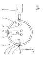
- schematisch die Draufsicht auf den Elektrolichtbogenofen nach
Fig. 1 und - Fig. 3
- die Einzelheit "X" gemäß
Fig. 1 . - In den Figuren ist ein Elektrolichtbogenofen 1 schematisch skizziert. Dieser hat ein gemauertes Bodengefäß 2, in dem schmelzflüssiges Material 3, insbesondere in Form von Stahl, aufgenommen werden kann (bedeckt von einer Schlackeschicht). Ein Deckel 5 deckt das Bodengefäß 2 ab. Drei im Deckel 5 angeordnete Elektroden 14 sind oberhalb des Pegels des schmelzflüssigen Materials 3 angeordnet. In bekannter Weise wird durch Aufbau eines Potentials zwischen Elektroden 14 und Material 3 ein Lichtbogen 4 erzeugt, der den Schmelzprozess des Materials 3 hervorruft.
- An einer Stelle 6 befindet sich im Deckel 5 eine Austrittsöffnung für das Ofengas, das von hier zu einer Entstaubungsanlage 8 geleitet wird. Zur Nachverbrennung im Ofeninneren wird sauerstoffhaltiges Gas G (das auch technisch reiner Sauerstoff sein kann) in das Ofeninnere geleitet; dies erfolgt über eine Eintrittsöffnung 9.
- Wie in der Zusammenschau der
Figuren 1 und2 gesehen werden kann, sind dabei die Austrittsöffnung 7 und die Eintrittsöffnung 9 quasi diagonal im Ofen angeordnet, d. h. sie haben voneinander den maximal möglichen Abstand (wenn man die Austrittsöffnung 7 als gegeben voraussetzt). - Ferner ergibt sich - was am besten aus
Fig. 3 hervorgeht -, dass das sauerstoffhaltige Gas G mittels mindestens eines Eingabeelement 11 in Form eines Diffusors ins Ofeninnere gebracht wird. Der Diffusor weist - im Unterschied zu einer Gasdüse - in seinem Endbereich eine trichterförmige Verbreiterung 13 auf, so dass das austretende Gas nicht beschleunigt, sondern verlangsamt wird. Angestrebt wird nämlich, dass das Gas mit möglichst geringer Ausströmgeschwindigkeit v das Eingabeelement 11 in Austrittsrichtung S verlässt. - Das Gas soll quasi durch die Schrottschüttung gezogen werden. Hierzu ist die Austrittsrichtung S des Eingabeelements 11 zur Ofenmitte hin ausgerichtet, so dass das Gas drallfrei ins Ofeninnere eintritt. Dabei kann die Austrittsrichtung S radial ausgerichtet sein; dargestellt ist indes, dass die Austrittsrichtung S unter einem kleinen Winkel α (vorzugsweise zwischen 5° und 15°) zur Horizontalen nach unten weist.
- Das mindestens eine Eingabeelement 11 ist dabei möglichst tief im Bodengefäß 2 angeordnet. In
Fig. 1 ist zu sehen, dass das Bodengefäß 2 ausgelegt ist, schmelzflüssiges Material 3 bis zu einer maximalen Pegelhöhe von h aufzunehmen. Das mindestens eine Eingabeelement 11 ist in einem Höhen-Bereich Δh über h angeordnet. Diese zusätzliche Höhe Δh ist möglichst gering zu wählen und hängt vom Grad der Verbärungen ab, die zu erwarten sind. - Die Anordnung des Eingabeelements 11 in der Wandung 10 des Bodengefäßes 2 ist aus
Fig. 3 ersichtlich. - Das Eingabeelement 11 wird von einer Halterung 15 getragen, die an der Wandung 10 des Bodengefäßes 2 angeschweißt ist, insbesondere an dem Außenpanel der Wandung 10.
- Über die Zuleitung 12 wird das sauerstoffhaltige Gas G dem Eingabeelement 11 zugeführt. Die trichterförmige Verbreiterung 13 stellt eine geringe Ausströmgeschwindigkeit v des Gases G ins Ofeninnere sicher.
- Vorteilhaft ist auch die Anordnung mehrerer baugleicher Eingabeelemente 11 horizontal nebeneinander oder zwei oder mehrreihig übereinander in unmittelbarer Nachbarschaft. Alle Eingabeelemente 11 können über eine Zuleitung 12 mit Gas G versorgt werden.
-
- 1
- Elektrolichtbogenofen
- 2
- Bodengefäß
- 3
- schmelzflüssiges Material (Stahl)
- 4
- Lichtbogen
- 5
- Deckel
- 6
- Stelle der Austrittsöffnung
- 7
- Austrittsöffnung
- 8
- Entstaubungsanlage
- 9
- Eintrittsöffnung
- 10
- Wandung des Bodengefäßes
- 11
- Eingabeelement
- 12
- Zuleitung
- 13
- trichterförmige Verbreiterung
- 14
- Elektrode
- 15
- Halterung
- G
- sauerstoffhaltiges Gas
- h
- maximale Pegelhöhe
- Δh
- Bereich oberhalb der maximalen Pegelhöhe
- v
- Ausströmgeschwindigkeit
- S
- Austrittsrichtung
- α
- Winkel
Claims (7)
- Verfahren zum Betrieb eines Elektrolichtbogenofens (1), bei dem sich in einem Bodengefäß (2) befindliches schmelzflüssiges Material (3), insbesondere Stahl, mit mindestens einem Lichtbogen (4) erhitzt wird, wobei auf dem Bodengefäß (2) ein Deckel (5) angeordnet ist, wobei an zumindest einer Stelle (6) des Elektrolichtbogenofens (1) eine Austrittsöffnung (7) angeordnet ist, von der aus Ofenabgase aus dem Ofeninneren heraus geleitet und einer Entstaubungsanlage (8) zugeführt werden und wobei zur Nachverbrennung ein sauerstoffhaltiges Gas (G) in das Ofeninnere eingeleitet wird,
wobei die Einleitung des sauerstoffhaltigen Gases (G) an einer Eintrittsöffnung (9) erfolgt, die von der Austrittsöffnung (7) beabstandet ist, wobei das sauerstoffhaltige Gas (G) mittels mindestens eines Eingabeelements (11) in das Ofeninnere einströmen gelassen wird,
wobei das mindestens eine Eingabeelement (11) radial ausgerichtet in der Wandung (10) des Bodengefäßes (2) angeordnet ist oder wobei das mindestens eine Eingabeelement (1) zur Ofenmitte hin ausgerichtet in der Wandung (10) des Bodengefäßes (2) angeordnet ist,
wobei die Austrittsrichtung (S) des Eingabeelements (11) zur Horizontalen einen Winkel (α) zwischen 5° und 15° nach unten einschließt,
wobei das sauerstoffhaltige Gas (G) so über das mindestens eine Eingabeelement (11) in das Ofeninnere einströmen gelassen wird, dass es eine Ausströmgeschwindigkeit (v) von weniger als 5 m/s aufweist,
wobei das sauerstoffhaltige Gas (G) über eine Zuleitung (12) dem mindestens einen Eingabeelement (11) zugeführt wird und das Gas (G) in der Zuleitung (12) unmittelbar vor dem Erreichen des Eingabeelements (11) einen Überdruck gegenüber dem Druck im Elektrolicht-bogenofen (1) von maximal 0,5 bar, vorzugsweise von maximal 0,25 bar, aufweist. - Verfahren nach Anspruch 1, dadurch gekennzeichnet, dass die Austrittsöffnung (7) im Deckel (5) angeordnet ist, wobei das Bodengefäß (2) und der Deckel (5) eine im wesentlichen runde Grundform haben und wobei sich die Austrittsöffnung (7) und die Eintrittsöffnung (9) diagonal gegenüberliegen.
- Verfahren nach Anspruch 2, dadurch gekennzeichnet, dass abgesehen von der Eingabe von sauerstoffhaltigem Gas (G) an der diagonal von der Austrittsöffnung (7) angeordneten Eintrittsöffnung (9) keine Eingabe von sauerstoffhaltigem Gas (G) mit einer Geschwindigkeit über 5 m/s erfolgt.
- Verfahren nach einem der Ansprüche 1 bis 3, dadurch gekennzeichnet, dass das Bodengefäß (2) zur Aufnahme von schmelzflüssigem Material bis zu einer maximalen Pegelhöhe (h) ausgebildet ist, wobei die Eintrittsöffnung (9) in einem Bereich (Δh) zwischen 20 und 150 cm oberhalb der maximalen Pegelhöhe (h) angeordnet ist.
- Verfahren nach einem der Ansprüche 1 bis 4, dadurch gekennzeichnet, dass das sauerstoffhaltige Gas (G) über mehrere Eingabeelemente (11) eingegeben wird, die parallel horizontal nebeneinander und/oder in vertikale Richtung übereinander angeordnet sind.
- Verfahren nach Anspruch 5, dadurch gekennzeichnet, dass alle Eingabeelemente (11) am Umfang der Wandung (10) horizontal nebeneinander so angeordnet sind, dass sie einen Umfangsabschnitt von maximal 270° besetzen.
- Verfahren nach einem der Ansprüche 1 bis 6, dadurch gekennzeichnet, dass das mindestens eine Eingabeelement (1) in seinem Austritts-endbereich eine trichterförmige Verbreiterung (13) aufweist.
Applications Claiming Priority (2)
| Application Number | Priority Date | Filing Date | Title |
|---|---|---|---|
| DE102011016943A DE102011016943A1 (de) | 2011-04-13 | 2011-04-13 | Verfahren zum Betrieb eines Elektrolichtbogenofens |
| PCT/EP2012/001331 WO2012139708A1 (de) | 2011-04-13 | 2012-03-27 | Verfahren zum betrieb eines elektrolichtbogenofens |
Publications (2)
| Publication Number | Publication Date |
|---|---|
| EP2697587A1 EP2697587A1 (de) | 2014-02-19 |
| EP2697587B1 true EP2697587B1 (de) | 2015-02-18 |
Family
ID=45922640
Family Applications (1)
| Application Number | Title | Priority Date | Filing Date |
|---|---|---|---|
| EP12711347.0A Active EP2697587B1 (de) | 2011-04-13 | 2012-03-27 | Verfahren zum betrieb eines elektrolichtbogenofens |
Country Status (3)
| Country | Link |
|---|---|
| EP (1) | EP2697587B1 (de) |
| DE (1) | DE102011016943A1 (de) |
| WO (1) | WO2012139708A1 (de) |
Family Cites Families (2)
| Publication number | Priority date | Publication date | Assignee | Title |
|---|---|---|---|---|
| DE2541086A1 (de) * | 1975-09-15 | 1977-03-17 | Toshin Steel Co | Verfahren und vorrichtung zur stahlerzeugung |
| FR2735563B1 (fr) | 1995-06-19 | 1997-07-25 | Air Liquide | Procede de fusion d'une charge dans un four |
-
2011
- 2011-04-13 DE DE102011016943A patent/DE102011016943A1/de not_active Ceased
-
2012
- 2012-03-27 EP EP12711347.0A patent/EP2697587B1/de active Active
- 2012-03-27 WO PCT/EP2012/001331 patent/WO2012139708A1/de not_active Ceased
Also Published As
| Publication number | Publication date |
|---|---|
| DE102011016943A1 (de) | 2012-10-18 |
| EP2697587A1 (de) | 2014-02-19 |
| WO2012139708A1 (de) | 2012-10-18 |
Similar Documents
| Publication | Publication Date | Title |
|---|---|---|
| DE10029983C2 (de) | Verfahren und Vorrichtung zum Schmelzen und Läutern von Glas mit Wärmerückgewinnung | |
| DE69332574T2 (de) | Verfahren und Vorrichtung zur Vakuumentgasung von Stahlschmelzen | |
| DE2504946C2 (de) | Verfahren und Vorrichtung zum Einschmelzen von Schrott, Eisenschwamm, Pellets oder dgl | |
| EP2171101B1 (de) | Schachtofen und verfahren zum betreiben eines schachtofens | |
| DD157915A5 (de) | Verfahren und vorrichtung zur herstellung von fluessigem roheisen oder stahlvormaterial | |
| DE1433431A1 (de) | Schmelzofen zur Herstellung von Stahl und Verfahren zum Betrieb des Ofens | |
| DE2062144A1 (de) | Verfahren und Vertikalofen fur die Schmelzraffination von Kupfer | |
| EP1080236A1 (de) | Variabel einsetzbare kombilanze mit verschiebbaren brenner- und blaslanzenkörpern | |
| EP2215418B1 (de) | Verfahren zum herstellen und schmelzen von flüssigem roheisen oder flüssigen stahlvorprodukten in einem einschmelzvergaser | |
| EP2734649B1 (de) | Schmelzreduktionsaggregat und verfahren zum betrieb eines schmelzreduktionsaggregats | |
| WO2012139708A1 (de) | Verfahren zum betrieb eines elektrolichtbogenofens | |
| EP1948833B1 (de) | Verfahren zum betreiben eines schachtofens | |
| EP1090148B1 (de) | Elektrolichtbogenofen | |
| EP2253916B1 (de) | Metallurgisches Schmelz- und Behandlungsaggregat | |
| DE69700267T2 (de) | Verfahren zum Beschicken eines Kupolofens mit Schrott und Koks | |
| EP4449038A1 (de) | Schmelzaggregat zur stahlerzeugung mit einem abstichgewicht zwischen 60 t und 350 t | |
| EP2653568A1 (de) | Vorrichtung und Verfahren zur Flächenbegasung in einem Reduktionsreaktorschacht | |
| DE102004010407B4 (de) | Reaktor zur thermischen Abfallbehandlung | |
| DE10117962A1 (de) | Verfahren zur thermischen Behandlung von Rohmaterialien und eine Vorrichtung zur Durchführung des Verfahrens | |
| EP2095051B1 (de) | Metallurgisches gefäss, insbesondere lichtbogenofen | |
| DE102012016142B3 (de) | Heißwindlanze mit einem am Heißwindaustritt angeordneten Düsenstein | |
| EP2440872A1 (de) | Verfahren zum betrelben eines bodenspülsystems eines bof-konverters | |
| DE10317195A1 (de) | Verfahren zur Verbesserung der Energiezufuhr in ein Schrotthaufwerk | |
| DE244496C (de) | ||
| DE29807145U1 (de) | Variabel einsetzbare Kombilanze |
Legal Events
| Date | Code | Title | Description |
|---|---|---|---|
| PUAI | Public reference made under article 153(3) epc to a published international application that has entered the european phase |
Free format text: ORIGINAL CODE: 0009012 |
|
| 17P | Request for examination filed |
Effective date: 20131008 |
|
| AK | Designated contracting states |
Kind code of ref document: A1 Designated state(s): AL AT BE BG CH CY CZ DE DK EE ES FI FR GB GR HR HU IE IS IT LI LT LU LV MC MK MT NL NO PL PT RO RS SE SI SK SM TR |
|
| DAX | Request for extension of the european patent (deleted) | ||
| GRAP | Despatch of communication of intention to grant a patent |
Free format text: ORIGINAL CODE: EPIDOSNIGR1 |
|
| INTG | Intention to grant announced |
Effective date: 20140924 |
|
| GRAS | Grant fee paid |
Free format text: ORIGINAL CODE: EPIDOSNIGR3 |
|
| GRAA | (expected) grant |
Free format text: ORIGINAL CODE: 0009210 |
|
| AK | Designated contracting states |
Kind code of ref document: B1 Designated state(s): AL AT BE BG CH CY CZ DE DK EE ES FI FR GB GR HR HU IE IS IT LI LT LU LV MC MK MT NL NO PL PT RO RS SE SI SK SM TR |
|
| REG | Reference to a national code |
Ref country code: GB Ref legal event code: FG4D Free format text: NOT ENGLISH |
|
| REG | Reference to a national code |
Ref country code: CH Ref legal event code: EP |
|
| REG | Reference to a national code |
Ref country code: AT Ref legal event code: REF Ref document number: 710828 Country of ref document: AT Kind code of ref document: T Effective date: 20150315 |
|
| REG | Reference to a national code |
Ref country code: IE Ref legal event code: FG4D Free format text: LANGUAGE OF EP DOCUMENT: GERMAN |
|
| REG | Reference to a national code |
Ref country code: DE Ref legal event code: R096 Ref document number: 502012002292 Country of ref document: DE Effective date: 20150402 |
|
| REG | Reference to a national code |
Ref country code: NL Ref legal event code: VDEP Effective date: 20150218 |
|
| REG | Reference to a national code |
Ref country code: LT Ref legal event code: MG4D |
|
| PG25 | Lapsed in a contracting state [announced via postgrant information from national office to epo] |
Ref country code: LT Free format text: LAPSE BECAUSE OF FAILURE TO SUBMIT A TRANSLATION OF THE DESCRIPTION OR TO PAY THE FEE WITHIN THE PRESCRIBED TIME-LIMIT Effective date: 20150218 Ref country code: SE Free format text: LAPSE BECAUSE OF FAILURE TO SUBMIT A TRANSLATION OF THE DESCRIPTION OR TO PAY THE FEE WITHIN THE PRESCRIBED TIME-LIMIT Effective date: 20150218 Ref country code: NO Free format text: LAPSE BECAUSE OF FAILURE TO SUBMIT A TRANSLATION OF THE DESCRIPTION OR TO PAY THE FEE WITHIN THE PRESCRIBED TIME-LIMIT Effective date: 20150518 Ref country code: ES Free format text: LAPSE BECAUSE OF FAILURE TO SUBMIT A TRANSLATION OF THE DESCRIPTION OR TO PAY THE FEE WITHIN THE PRESCRIBED TIME-LIMIT Effective date: 20150218 Ref country code: HR Free format text: LAPSE BECAUSE OF FAILURE TO SUBMIT A TRANSLATION OF THE DESCRIPTION OR TO PAY THE FEE WITHIN THE PRESCRIBED TIME-LIMIT Effective date: 20150218 Ref country code: FI Free format text: LAPSE BECAUSE OF FAILURE TO SUBMIT A TRANSLATION OF THE DESCRIPTION OR TO PAY THE FEE WITHIN THE PRESCRIBED TIME-LIMIT Effective date: 20150218 |
|
| PG25 | Lapsed in a contracting state [announced via postgrant information from national office to epo] |
Ref country code: NL Free format text: LAPSE BECAUSE OF FAILURE TO SUBMIT A TRANSLATION OF THE DESCRIPTION OR TO PAY THE FEE WITHIN THE PRESCRIBED TIME-LIMIT Effective date: 20150218 Ref country code: LV Free format text: LAPSE BECAUSE OF FAILURE TO SUBMIT A TRANSLATION OF THE DESCRIPTION OR TO PAY THE FEE WITHIN THE PRESCRIBED TIME-LIMIT Effective date: 20150218 Ref country code: IS Free format text: LAPSE BECAUSE OF FAILURE TO SUBMIT A TRANSLATION OF THE DESCRIPTION OR TO PAY THE FEE WITHIN THE PRESCRIBED TIME-LIMIT Effective date: 20150618 Ref country code: RS Free format text: LAPSE BECAUSE OF FAILURE TO SUBMIT A TRANSLATION OF THE DESCRIPTION OR TO PAY THE FEE WITHIN THE PRESCRIBED TIME-LIMIT Effective date: 20150218 Ref country code: GR Free format text: LAPSE BECAUSE OF FAILURE TO SUBMIT A TRANSLATION OF THE DESCRIPTION OR TO PAY THE FEE WITHIN THE PRESCRIBED TIME-LIMIT Effective date: 20150519 |
|
| PG25 | Lapsed in a contracting state [announced via postgrant information from national office to epo] |
Ref country code: RO Free format text: LAPSE BECAUSE OF FAILURE TO SUBMIT A TRANSLATION OF THE DESCRIPTION OR TO PAY THE FEE WITHIN THE PRESCRIBED TIME-LIMIT Effective date: 20150218 Ref country code: EE Free format text: LAPSE BECAUSE OF FAILURE TO SUBMIT A TRANSLATION OF THE DESCRIPTION OR TO PAY THE FEE WITHIN THE PRESCRIBED TIME-LIMIT Effective date: 20150218 Ref country code: SK Free format text: LAPSE BECAUSE OF FAILURE TO SUBMIT A TRANSLATION OF THE DESCRIPTION OR TO PAY THE FEE WITHIN THE PRESCRIBED TIME-LIMIT Effective date: 20150218 Ref country code: DK Free format text: LAPSE BECAUSE OF FAILURE TO SUBMIT A TRANSLATION OF THE DESCRIPTION OR TO PAY THE FEE WITHIN THE PRESCRIBED TIME-LIMIT Effective date: 20150218 Ref country code: CZ Free format text: LAPSE BECAUSE OF FAILURE TO SUBMIT A TRANSLATION OF THE DESCRIPTION OR TO PAY THE FEE WITHIN THE PRESCRIBED TIME-LIMIT Effective date: 20150218 |
|
| REG | Reference to a national code |
Ref country code: CH Ref legal event code: PL |
|
| REG | Reference to a national code |
Ref country code: DE Ref legal event code: R097 Ref document number: 502012002292 Country of ref document: DE |
|
| PG25 | Lapsed in a contracting state [announced via postgrant information from national office to epo] |
Ref country code: MC Free format text: LAPSE BECAUSE OF FAILURE TO SUBMIT A TRANSLATION OF THE DESCRIPTION OR TO PAY THE FEE WITHIN THE PRESCRIBED TIME-LIMIT Effective date: 20150218 Ref country code: PL Free format text: LAPSE BECAUSE OF FAILURE TO SUBMIT A TRANSLATION OF THE DESCRIPTION OR TO PAY THE FEE WITHIN THE PRESCRIBED TIME-LIMIT Effective date: 20150218 |
|
| PLBE | No opposition filed within time limit |
Free format text: ORIGINAL CODE: 0009261 |
|
| STAA | Information on the status of an ep patent application or granted ep patent |
Free format text: STATUS: NO OPPOSITION FILED WITHIN TIME LIMIT |
|
| PG25 | Lapsed in a contracting state [announced via postgrant information from national office to epo] |
Ref country code: IT Free format text: LAPSE BECAUSE OF FAILURE TO SUBMIT A TRANSLATION OF THE DESCRIPTION OR TO PAY THE FEE WITHIN THE PRESCRIBED TIME-LIMIT Effective date: 20150218 |
|
| REG | Reference to a national code |
Ref country code: FR Ref legal event code: ST Effective date: 20151130 |
|
| REG | Reference to a national code |
Ref country code: IE Ref legal event code: MM4A |
|
| 26N | No opposition filed |
Effective date: 20151119 |
|
| PG25 | Lapsed in a contracting state [announced via postgrant information from national office to epo] |
Ref country code: LI Free format text: LAPSE BECAUSE OF NON-PAYMENT OF DUE FEES Effective date: 20150331 Ref country code: CH Free format text: LAPSE BECAUSE OF NON-PAYMENT OF DUE FEES Effective date: 20150331 Ref country code: IE Free format text: LAPSE BECAUSE OF NON-PAYMENT OF DUE FEES Effective date: 20150327 |
|
| PG25 | Lapsed in a contracting state [announced via postgrant information from national office to epo] |
Ref country code: FR Free format text: LAPSE BECAUSE OF NON-PAYMENT OF DUE FEES Effective date: 20150420 Ref country code: SI Free format text: LAPSE BECAUSE OF FAILURE TO SUBMIT A TRANSLATION OF THE DESCRIPTION OR TO PAY THE FEE WITHIN THE PRESCRIBED TIME-LIMIT Effective date: 20150218 |
|
| GBPC | Gb: european patent ceased through non-payment of renewal fee |
Effective date: 20160327 |
|
| PG25 | Lapsed in a contracting state [announced via postgrant information from national office to epo] |
Ref country code: MT Free format text: LAPSE BECAUSE OF FAILURE TO SUBMIT A TRANSLATION OF THE DESCRIPTION OR TO PAY THE FEE WITHIN THE PRESCRIBED TIME-LIMIT Effective date: 20150218 |
|
| PG25 | Lapsed in a contracting state [announced via postgrant information from national office to epo] |
Ref country code: GB Free format text: LAPSE BECAUSE OF NON-PAYMENT OF DUE FEES Effective date: 20160327 |
|
| PG25 | Lapsed in a contracting state [announced via postgrant information from national office to epo] |
Ref country code: BG Free format text: LAPSE BECAUSE OF FAILURE TO SUBMIT A TRANSLATION OF THE DESCRIPTION OR TO PAY THE FEE WITHIN THE PRESCRIBED TIME-LIMIT Effective date: 20150218 Ref country code: SM Free format text: LAPSE BECAUSE OF FAILURE TO SUBMIT A TRANSLATION OF THE DESCRIPTION OR TO PAY THE FEE WITHIN THE PRESCRIBED TIME-LIMIT Effective date: 20150218 Ref country code: HU Free format text: LAPSE BECAUSE OF FAILURE TO SUBMIT A TRANSLATION OF THE DESCRIPTION OR TO PAY THE FEE WITHIN THE PRESCRIBED TIME-LIMIT; INVALID AB INITIO Effective date: 20120327 |
|
| PG25 | Lapsed in a contracting state [announced via postgrant information from national office to epo] |
Ref country code: CY Free format text: LAPSE BECAUSE OF FAILURE TO SUBMIT A TRANSLATION OF THE DESCRIPTION OR TO PAY THE FEE WITHIN THE PRESCRIBED TIME-LIMIT Effective date: 20150218 |
|
| PG25 | Lapsed in a contracting state [announced via postgrant information from national office to epo] |
Ref country code: BE Free format text: LAPSE BECAUSE OF NON-PAYMENT OF DUE FEES Effective date: 20150331 Ref country code: PT Free format text: LAPSE BECAUSE OF FAILURE TO SUBMIT A TRANSLATION OF THE DESCRIPTION OR TO PAY THE FEE WITHIN THE PRESCRIBED TIME-LIMIT Effective date: 20150618 |
|
| PG25 | Lapsed in a contracting state [announced via postgrant information from national office to epo] |
Ref country code: TR Free format text: LAPSE BECAUSE OF FAILURE TO SUBMIT A TRANSLATION OF THE DESCRIPTION OR TO PAY THE FEE WITHIN THE PRESCRIBED TIME-LIMIT Effective date: 20150218 |
|
| PG25 | Lapsed in a contracting state [announced via postgrant information from national office to epo] |
Ref country code: LU Free format text: LAPSE BECAUSE OF NON-PAYMENT OF DUE FEES Effective date: 20150327 |
|
| REG | Reference to a national code |
Ref country code: AT Ref legal event code: MM01 Ref document number: 710828 Country of ref document: AT Kind code of ref document: T Effective date: 20170327 |
|
| PG25 | Lapsed in a contracting state [announced via postgrant information from national office to epo] |
Ref country code: MK Free format text: LAPSE BECAUSE OF FAILURE TO SUBMIT A TRANSLATION OF THE DESCRIPTION OR TO PAY THE FEE WITHIN THE PRESCRIBED TIME-LIMIT Effective date: 20150218 |
|
| PG25 | Lapsed in a contracting state [announced via postgrant information from national office to epo] |
Ref country code: AT Free format text: LAPSE BECAUSE OF NON-PAYMENT OF DUE FEES Effective date: 20170327 |
|
| PG25 | Lapsed in a contracting state [announced via postgrant information from national office to epo] |
Ref country code: AL Free format text: LAPSE BECAUSE OF FAILURE TO SUBMIT A TRANSLATION OF THE DESCRIPTION OR TO PAY THE FEE WITHIN THE PRESCRIBED TIME-LIMIT Effective date: 20150218 |
|
| P01 | Opt-out of the competence of the unified patent court (upc) registered |
Effective date: 20230512 |
|
| PGFP | Annual fee paid to national office [announced via postgrant information from national office to epo] |
Ref country code: DE Payment date: 20260113 Year of fee payment: 15 |