EP2697478B1 - Cimentation etagée a l'aide d'un outil à vanne à manchon coulissant - Google Patents
Cimentation etagée a l'aide d'un outil à vanne à manchon coulissant Download PDFInfo
- Publication number
- EP2697478B1 EP2697478B1 EP12715795.6A EP12715795A EP2697478B1 EP 2697478 B1 EP2697478 B1 EP 2697478B1 EP 12715795 A EP12715795 A EP 12715795A EP 2697478 B1 EP2697478 B1 EP 2697478B1
- Authority
- EP
- European Patent Office
- Prior art keywords
- packer
- tubular
- piston assembly
- tool
- tubular body
- Prior art date
- Legal status (The legal status is an assumption and is not a legal conclusion. Google has not performed a legal analysis and makes no representation as to the accuracy of the status listed.)
- Active
Links
- 238000000034 method Methods 0.000 title claims description 22
- 239000004568 cement Substances 0.000 claims description 42
- 239000012530 fluid Substances 0.000 claims description 25
- 239000003795 chemical substances by application Substances 0.000 claims description 14
- 238000004891 communication Methods 0.000 claims description 11
- 238000007789 sealing Methods 0.000 claims description 9
- 229910044991 metal oxide Inorganic materials 0.000 claims description 7
- 150000004706 metal oxides Chemical class 0.000 claims description 7
- 230000003213 activating effect Effects 0.000 claims description 4
- 150000001875 compounds Chemical class 0.000 claims description 4
- 230000004888 barrier function Effects 0.000 claims description 3
- BRPQOXSCLDDYGP-UHFFFAOYSA-N calcium oxide Chemical compound [O-2].[Ca+2] BRPQOXSCLDDYGP-UHFFFAOYSA-N 0.000 claims description 3
- ODINCKMPIJJUCX-UHFFFAOYSA-N calcium oxide Inorganic materials [Ca]=O ODINCKMPIJJUCX-UHFFFAOYSA-N 0.000 claims description 3
- 239000000292 calcium oxide Substances 0.000 claims description 3
- 230000015572 biosynthetic process Effects 0.000 description 6
- 230000008569 process Effects 0.000 description 4
- 238000012986 modification Methods 0.000 description 2
- 230000004048 modification Effects 0.000 description 2
- 230000009467 reduction Effects 0.000 description 2
- 239000004215 Carbon black (E152) Substances 0.000 description 1
- VYPSYNLAJGMNEJ-UHFFFAOYSA-N Silicium dioxide Chemical compound O=[Si]=O VYPSYNLAJGMNEJ-UHFFFAOYSA-N 0.000 description 1
- 230000015556 catabolic process Effects 0.000 description 1
- 230000008878 coupling Effects 0.000 description 1
- 238000010168 coupling process Methods 0.000 description 1
- 238000005859 coupling reaction Methods 0.000 description 1
- 238000006073 displacement reaction Methods 0.000 description 1
- 239000002360 explosive Substances 0.000 description 1
- -1 farek oxide Chemical compound 0.000 description 1
- 229930195733 hydrocarbon Natural products 0.000 description 1
- 150000002430 hydrocarbons Chemical class 0.000 description 1
- 230000002706 hydrostatic effect Effects 0.000 description 1
- 238000002347 injection Methods 0.000 description 1
- 239000007924 injection Substances 0.000 description 1
- 239000000463 material Substances 0.000 description 1
- 229910052752 metalloid Inorganic materials 0.000 description 1
- 150000002738 metalloids Chemical class 0.000 description 1
- TWNQGVIAIRXVLR-UHFFFAOYSA-N oxo(oxoalumanyloxy)alumane Chemical compound O=[Al]O[Al]=O TWNQGVIAIRXVLR-UHFFFAOYSA-N 0.000 description 1
- 230000001105 regulatory effect Effects 0.000 description 1
- 239000002002 slurry Substances 0.000 description 1
- 230000003068 static effect Effects 0.000 description 1
- 238000006467 substitution reaction Methods 0.000 description 1
- XLYOFNOQVPJJNP-UHFFFAOYSA-N water Substances O XLYOFNOQVPJJNP-UHFFFAOYSA-N 0.000 description 1
Images


Classifications
-
- E—FIXED CONSTRUCTIONS
- E21—EARTH DRILLING; MINING
- E21B—EARTH DRILLING, e.g. DEEP DRILLING; OBTAINING OIL, GAS, WATER, SOLUBLE OR MELTABLE MATERIALS OR A SLURRY OF MINERALS FROM WELLS
- E21B33/00—Sealing or packing boreholes or wells
- E21B33/10—Sealing or packing boreholes or wells in the borehole
- E21B33/13—Methods or devices for cementing, for plugging holes, crevices, or the like
- E21B33/14—Methods or devices for cementing, for plugging holes, crevices, or the like for cementing casings into boreholes
- E21B33/146—Stage cementing, i.e. discharging cement from casing at different levels
-
- E—FIXED CONSTRUCTIONS
- E21—EARTH DRILLING; MINING
- E21B—EARTH DRILLING, e.g. DEEP DRILLING; OBTAINING OIL, GAS, WATER, SOLUBLE OR MELTABLE MATERIALS OR A SLURRY OF MINERALS FROM WELLS
- E21B21/00—Methods or apparatus for flushing boreholes, e.g. by use of exhaust air from motor
- E21B21/10—Valve arrangements in drilling-fluid circulation systems
- E21B21/103—Down-hole by-pass valve arrangements, i.e. between the inside of the drill string and the annulus
-
- E—FIXED CONSTRUCTIONS
- E21—EARTH DRILLING; MINING
- E21B—EARTH DRILLING, e.g. DEEP DRILLING; OBTAINING OIL, GAS, WATER, SOLUBLE OR MELTABLE MATERIALS OR A SLURRY OF MINERALS FROM WELLS
- E21B2200/00—Special features related to earth drilling for obtaining oil, gas or water
- E21B2200/06—Sleeve valves
Definitions
- the present invention relates to an apparatus for use while completing a subterranean hydrocarbon producing well. More specifically, the invention relates to an apparatus for the staging of cement between casing and a wellbore.
- casing When completing a subterranean well, casing is typically inserted into the wellbore and secured in place by injecting cement within the casing. The cement is then forced through a lower end of the casing and into an annulus between the casing and wellbore wall.
- a wiper plug is typically used for pushing the cement from the casing.
- a displacement fluid such as water, or an appropriately weighted mud is pumped into the casing above the plug, the pressurized fluid serves as a motive force to urge the plug downward through the casing to extrude the cement from the casing outlet and back up into the annulus.
- the hydraulics for cementing the casing wellbore annulus in a substantially deep well makes the single stage cement injection process impracticable.
- cement is not provided in portions of the well, where the well formation pressure is less than well hydrostatic pressure, or where the formation is too porous so high cement slurry pressure in the case induces formation breakdown, which leads to losses in the formation, as a result, no cement is present.
- the casing string is cemented in sections, which is known as a staging process.
- Staging involves placing cement staging tools integral within the casing string; the staging tools allow cement to flow downward therethrough to a lower section of the casing string during primary or first stage cementing operations.
- the staging tool selectively closes its bore and opens a side port to divert cement into the surrounding annulus where the cement can flow upwards in the annulus.
- the cement staging tools also are equipped with packers for sealing the annular area between the tool and wellbore.
- US-A-3.527.299 discloses a downhole cementing tool having the features of the pre-characterizing portion of claim 1.
- the downhole tool 24 is made up of a tubular body 25 integrally formed within a casing string where a port 46 is formed through a wall of the tubular body 25.
- An inflatable packer 66 is included that circumscribes a portion of the tubular body 25 and an annular cylinder 56 is provided in the tubular body 25 that is in fluid communication with the packer 66.
- a sleeve 54 is set coaxially within the tubular body 25 and selectively changeable between a pass through and by-pass configuration. When in the pass through configuration the sleeve 54 defines a flow barrier between an annulus of the tubular body 25 and the port.
- the annulus of the tubular body 25 is in fluid communication with the port 46 and having a portion of the sleeve 54 inserted into the cylinder 56. Also included is a fluid disposed in the cylinder 56 and remains in the cylinder 56 when the sleeve 54 is set in the pass through configuration and is pushed into the packer 66 when the sleeve 54 is in the by-pass configuration for inflating the packer 66.
- a reactive compound is provided in the packer 66 for selectively expanding the packer 66.
- the reactive compound comprises a metal oxide.
- the metal oxide comprises calcium oxide.
- a ball seat disposed in the sleeve 54, in this example embodiment the ball seat has a profiled shoulder configured for receiving a ball therein.
- a sealing interface may be formed along where the ball contacts the shoulder, so that when a force is applied to the ball to urge the ball against the shoulder, the sleeve 54 is moved into the by-pass configuration.
- a spring may be engaged with the sleeve 54, where the spring becomes compressed as the sleeve 54 is moved into the by-pass configuration, so that when the force applied to the ball is removed, the spring returns to an uncompressed state and moves the sleeve 54 to the pass through configuration.
- the fluid is selectively pressurized on an upper surface of the ball to generate the force applied to the ball.
- a stage cementing tool is included with the tubular, where the stage cementing tool is made up of a tubular body 25 having a passage formed through a sidewall of the tubular body 25.
- an inflatable packer 66 that circumscribes a portion of the tubular body 25.
- a sleeve 54 that can slide within the tubular body 25 and fluid that is in communication with the sleeve 54 and the packer 66. The method further includes simultaneously inflating the packer 66 and flowing cement from within the tubular into an annulus between the tubular and the wellbore.
- the stage cementing tool further comprises an expanding agent in the packer 66, the method further comprising selectively activating the expanding agent for inflating the packer 66.
- the expanding agent includes a metal oxide.
- selectively activating the expanding agent can involve introducing moisture to the expanding agent.
- the packer 66 expands radially outward from the stage cementing tool and forms a sealing interface with a wall of the wellbore.
- the stage cementing tool is a first stage cementing tool and the method further involves repeating the above steps of inflating the packer 66 and flowing cement from within the tubular into an annulus between the tubular and the wellbore and at a depth above the first stage cement tool.
- cement introduced into the annulus at each stage cementing tool flows in the annulus downward where is supported on a lower end by a packer to wellbore interface formed at a lower adjacent stage cementing tool.
- FIG. 1 Shown in side sectional view in Figure 1 is an example of a string of casing 10 set in a wellbore 12.
- the casing 10 is shown supported on its upper end by a wellhead assembly 14 disposed at the entrance to the wellbore 12 on the surface.
- cement 16 is shown being inserted into an annulus 18 formed between the casing 10 and walls of the wellbore 12.
- the cement 16 secures the casing 10 to the formation 20 that circumscribes the wellbore 12.
- the cement 16 may be injected into the casing 10 via the wellhead assembly 14, a plug 22 can be inserted into the casing 10 above the cement 16. Pressure applied to the upper end of the plug 22 urges the plug and cement 16 through and out of the bottom of the casing 10.
- the cement 16 After exiting the casing 10, the cement 16 flows into the lower end of the annulus 18 and upwards within the annulus 18. How far up the annulus 18 the cement 16 flows is dictated by the pressure at the bottom end of the casing 10. To overcome the high static pressures faced when cementing deep wellbores, cementing may require multiple stages at various depths along the casing to limit the amount of pressure applied into the casing 10 from the surface.
- an example embodiments of staging tools 24 are shown included at locations within the string of casing 10. In the embodiment of Figure 1 , the upper level of the cement 16, in the initial cementing step, is generally maintained at a depth below the staging tool 24.
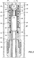
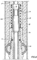
- the staging tool 24 is illustrated as a generally annular device having an annular body 25 with a tubular piston assembly 26 inserted within the body 25.
- a lip 27 On an upper end of the body 25 is a lip 27 that extends radially inward towards an axis A X of the staging tool 24.
- the piston assembly 26 has a piston body 28 shown generally coaxial with the body 25 also having a lip 30 on its upper end. Unlike the inwardly extending lip 27, the lip 30 of the piston body 28 extends radially outward from the upper end of the body 28.
- the lip 30 is shown axially urged against a lower surface of the lip 27 on the staging tool body 25.
- an annular space 32 is shown defined by the region bounded on its lateral sides by the outer circumference of the body 28 and the inner circumference of the tool body 25.
- the upper end of the annular space 32 is defined by a portion of the lower surface of the lip 30.
- a coiled spring 34 is shown set within the annular space 32 and, as will be described in more detail below, the spring 32 is selectively compressed and provides a restoring force for maintaining the piston body 28 in the configuration of Figure 2 .
- Optional O-ring seals 36 are shown on an outer circumference of the lip 30 that form a sealing interface between the piston assembly 26 and inner circumference of the tool body 25.
- An annular ball seat 38 is shown coupled to the inner circumference of the piston body 28 and depending radially inward towards the axis A X .
- a threaded connection 39 may be used for coupling the ball seat 38 with the piston body 28.
- An upwardly facing lateral surface of the ball seat 38 is shown having a profile that defines an upper face 40, wherein the upper face slopes downward and away from the lip 27 with distance away from the piston body 28 and approaching the axis A X .
- an axial vent 42 is shown formed through the body of the ball seat 38 thereby providing pressure communication from the upper face 40 and lower surface 43 of the ball seat 38.
- a ring-like piston head 44 Shown on an axial end of the piston assembly 26 opposite the lip 30 is a ring-like piston head 44 having optional O-ring seals on its inner and outer circumference. Radial ports 46 are further illustrated that are formed through a side wall of the body 25 and a location adjacent the annular space 32.
- the piston assembly 26, through its piston body 28, O-ring seals 36, and o-ring seals around the piston head 44 defines a flow barrier between the annulus 18 and inner confines of the staging tool 24. Accordingly, in the example configuration of Figure 2 , cement can flow through the string of casing 10 and the staging tool 24 to a lower depth as illustrated in Figure 1 .
- Optional screen filters 48 may be provided as shown within the circulating ports 46. The presence of the screen filters 48 may shield debris and other desired matter from entering the ports 46.
- An optional radial vent 50 is further illustrated through the side wall of the body 25 and between the outer circumference of the body 25 and into the annular space 32. As indicated above, the force of the spring 34 may exert a force on the piston assembly 26 that urges the lip 36 up against a lower surface of the lip 27 of the body 25.
- Shear pins 52 are shown inserted into a passage in the body 25 and a passage (shown registered with the passage in the body 25) depending radially inward from an outer surface on the piston body 28.
- a sleeve 54 is further illustrated that depends coaxially from a lower end of the piston body 28 and downward within a lower portion of the staging tool 24.
- the radial inward position of the sleeve 54 as well as an annular channel formed on an inner surface of the body 25 define an annular cylinder 56 that is disposed between the sleeve 54 and body 25.
- the upper end of the cylinder 56 is defined by lower surface of the piston head 44.
- a fluid 58 is shown provided within the annular cylinder 56.
- a fluid circuit 60 shown extending through the body 25, is made up of a flow line 62 with an integral check valve 64.
- the check valve 64 allows flow away from the cylinder 56 but prevents flow from returning the cylinder 56 across the check valve 64.
- the end of the fluid circuit 60 opposite where it communicates with the cylinder 56 is shown communicating with an inner circumference of an inflatable packer 66.
- the inflatable packer 66 circumscribes a portion of the outer surface of the body 25.
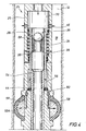
- FIG. 3 an example embodiment of the staging tool 24 is shown wherein a ball 68 has been dropped within the wellbore 12 and landed on the upper shoulder 40.
- the ball 68 defines a pressure seal along the interface of contact between the ball 68 and upper surface 40 of the ball seat 48. It should be pointed out however, that the dimensions of the ball 68 are such that the vent 42 remains in communication with the portions of the wellbore 12 above the ball 68.
- the annulus 70 may be pressurized in to generate a downward force, as represented by the arrow, on the upper surface of the ball 68 that is transferred to the ball seat 38.
- the transferred force on the ball seat 38 in turn downwardly urges the piston body 28 and compresses the spring 34.
- Continued application of downward force moves the upper end of the piston body 28 below the ports 46, thereby allowing fluid communication between the annulus 70 and annulus 18.
- an expandable agent 71 may be included in the space between the packer 66, 66A and body 25 that can be activated and expand in a non-explosive manner.
- the expandable agent include metal oxides or metalloid oxides, wherein examples are silicone dioxide, aluminum oxide, farek oxide, calcium oxide, and combinations thereof.
- the agent may be obtained from KMK Regulatory Services Inc., 1-888-447-7769. Further examples have the tradename Crack-a-Might®, Dexpan® and Split-AG®. As such, the packer 66, 66A may be expanded and set by application of a downward force resulting from pressure applied in the wellbore 12.
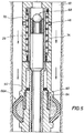
- the annulus 70 is again pressurized to apply a downward force onto the ball 68 thereby opening ports 46.
- Cement 16 may then be pumped into the annulus 70 where it flows through the staging tool 24 and is bypassed outward through the ports 46 and into the annulus 18 for securing the casing string 10 to the wall of the wellbore 12.
- any cement flowing down the wellbore 12 and into the annulus 70 may exit the staging tool 24 via the ports 46 for application of cement into the space between the casing string 10 ( Figure 1 ) and wellbore wall for securing the casing string within the wellbore 12.
- the flow of cement 16 also fills the space below the ports 46 and downward to the packer 66, 66A. As such, the cement 16 fills the space from the packer 66, 66A and upwards either to surface or to the next adjacently positioned staging tool 24.
- the pressure may be reduced within the annulus 70, so that the spring 34 may return the piston assembly 26 in the configuration of Figure 7 and so that the body of the piston 28 blocks flow between the annulus 70 and to the ports 46.
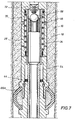
- a plug 72 is shown landed on top of the ball 68.
- the cement in the annulus 70 above the ball 68 may be removed and urged lower and out through the ports 46.
- FIG 8 an example embodiment of the portion of the casing string 10 having the staging tool 24 is shown after the plug 72 and ball 68 have been removed with a drill bit, or other subterranean excavating device.
- cement 16 is filling the annulus 18 thereby securing the portion of the casing as shown.
- a single springloaded piston may be employed to not only provide fluid communication from within the casing string into the annulus between the string and the formation, but may also be used for the step of inflating the packer 66, 66A and sealing in the space between the staging tool and wellbore.
- the implementation of the spring 34 means that the plug 72 may be used for wiping cement from the casing and is not required to close ports within the staging tool as is required in prior art references.
Claims (14)
- Outil de fond de trou (24) à utiliser dans l'achèvement d'un puits de forage comprenant :un corps tubulaire (25) pouvant être inséré dans une colonne de tubage ;un orifice (46) formé à travers une paroi du corps tubulaire (25) ;un élément d'obturation gonflable (66) entourant une partie du corps tubulaire (25) ;un cylindre annulaire (56) formé dans le corps tubulaire (25) et en communication fluidique avec l'élément d'obturation (66) ;caractérisé par,un ensemble de piston tubulaire (26) de manière coaxiale dans le corps tubulaire (25) sélectivement réglé dans une configuration passante et définissant une barrière d'écoulement entre un espace annulaire (70) du corps tubulaire (25) et l'orifice (46), et sélectivement coulissant dans une configuration de bypass avec l'espace annulaire (70) du corps tubulaire (25) en communication fluidique avec l'orifice (46) et présentant une partie de l'ensemble de piston tubulaire (26) insérée dans le cylindre annulaire (56) ;un fluide qui est dans le cylindre annulaire (56) lorsque l'ensemble de piston tubulaire (26) est réglé dans la configuration passante et dans l'élément d'obturation (66) lorsque l'ensemble de piston tubulaire (26) est dans la configuration de bypass ; etun ressort (34) mis en prise avec l'ensemble de piston tubulaire (26) et qui est comprimé quand l'ensemble de piston tubulaire (26) est forcé dans la configuration de bypass, de sorte que, lorsque la force appliquée à l'ensemble de piston tubulaire (26) est enlevé, le ressort (34) revient dans un état non-comprimé et force l'ensemble de piston tubulaire (26) en configuration passante.
- Outil de fond de trou (24) selon la revendication 1, caractérisé en outre par un composé réactif dans l'élément obturateur (66) permettant de dilater sélectivement l'élément obturateur (66).
- Outil de fond de trou (24) selon la revendication 2, caractérisé en ce que le composé réactif comprend un oxyde métallique.
- Outil de fond de trou (24) selon la revendication 3, caractérisé en ce que l'oxyde métallique comprend un oxyde de calcium.
- Outil de fond de trou (24) selon l'une quelconque des revendications 1 à 4, caractérisé en outre par un siège de bille (38) disposé dans l'ensemble de piston tubulaire (26), le siège de bille présentant un épaulement profilé configuré afin de recevoir une bille (68) à l'intérieur qui définit une interface d'étanchéité le long de l'endroit où la bille (68) entre en contact avec l'épaulement, de sorte que, lorsqu'une force est appliquée à la bille (68) afin de pousser la bille (68) contre l'épaulement, l'ensemble de piston tubulaire (26) est déplacé dans la configuration de bypass.
- Outil de fond de trou (24) selon l'une quelconque des revendications précédentes, caractérisé en outre par un circuit de fluide s'étendant à travers le corps tubulaire (25) et constitué de :une ligne d'écoulement (62) fournissant une communication fluidique entre un cylindre annulaire (56) et une circonférence interne d'un élément d'obturation gonflable (66) ; etun clapet de non-retour (64) qui permet au fluide de s'écouler depuis le cylindre annulaire (56) mais empêche l'écoulement de fluide de revenir vers le cylindre annulaire à travers le clapet de non-retour.
- Outil de fond de trou (24) selon la revendication 5, caractérisé en ce que le fluide est sélectivement pressurisé sur une surface supérieure de la bille (68) afin de générer la force appliquée à la bille (68).
- Procédé de cimentation d'une partie d'un élément tubulaire de fond de trou dans un puits de forage comprenant :(a) la fourniture d'un outil de cimentation étagé (24), l'outil de cimentation étagé comprenant : un corps tubulaire (25) présentant un orifice (46) formé à travers une paroi latérale du corps tubulaire (25), un élément d'obturation gonflable (66) entourant une partie du corps tubulaire (25), un ensemble de piston tubulaire (26) coulissant dans le corps tubulaire (25), un ressort (34) en prise avec l'ensemble de piston tubulaire (26) ; et un fluide en communication avec un manchon (54) et l'élément d'obturation (66) ;(b) le gonflage simultané de l'élément d'obturation (66) et l'écoulement de ciment depuis l'intérieur de l'élément tubulaire dans un cylindre annulaire et le puits de forage en appliquant une force afin de pousser l'ensemble de piston tubulaire (26) de manière axiale dans le corps tubulaire (25) depuis une position qui bloque l'écoulement à travers l'orifice (46) vers une position permettant l'écoulement à travers l'orifice (46) et le long d'un chemin qui force le fluide dans l'élément d'obturation (66) ; et(c) la suppression de la force de sorte que le ressort remette l'ensemble de piston tubulaire (26) dans la position qui bloque l'écoulement à travers le passage.
- Procédé selon la revendication 8, dans lequel l'outil de cimentation étagé (24) est en outre caractérisé par un agent dilatant dans l'élément d'obturation (66), le procédé comprenant en outre l'activation sélective de l'agent dilatant permettant de faire gonfler l'élément d'obturation (66).
- Procédé selon la revendication 9, caractérisé en ce que l'agent dilatant comprend un oxyde métallique.
- Procédé selon la revendication 9, caractérisé en ce que l'étape consistant à activer sélectivement l'agent dilatant comprend l'introduction d'humidité dans l'agent dilatant.
- Procédé selon l'une quelconque des revendications 8 à 11, caractérisé en ce que l'élément d'obturation (66) se dilate de manière radiale vers l'extérieur depuis l'outil de cimentation étagée (24) et forme une interface étanche avec une paroi du puits de forage.
- Procédé selon l'une quelconque des revendications 8 à 12, caractérisé en ce que le procédé comprend la fourniture d'un premier outil de cimentation étagée et le procédé comprenant en outre la répétition des étapes (a) et (b) à une profondeur supérieure au premier outil de cimentation étagée.
- Procédé selon la revendication 13, caractérisé en ce que le ciment introduit dans le cylindre annulaire à chaque outil de cimentation étagée s'écoule dans le cylindre annulaire vers le bas lorsqu'il est supporté sur une extrémité inférieure par une interface entre l'élément d'obstruction et le puits de forage formée au niveau d'un outil de cimentation étagée adjacent inférieur.
Applications Claiming Priority (2)
| Application Number | Priority Date | Filing Date | Title |
|---|---|---|---|
| US13/085,187 US8720561B2 (en) | 2011-04-12 | 2011-04-12 | Sliding stage cementing tool and method |
| PCT/US2012/033055 WO2012142112A1 (fr) | 2011-04-12 | 2012-04-11 | Outil et procédé de cimentation étagée avec vanne à fourreau coulissant |
Publications (2)
| Publication Number | Publication Date |
|---|---|
| EP2697478A1 EP2697478A1 (fr) | 2014-02-19 |
| EP2697478B1 true EP2697478B1 (fr) | 2020-04-01 |
Family
ID=45992863
Family Applications (1)
| Application Number | Title | Priority Date | Filing Date |
|---|---|---|---|
| EP12715795.6A Active EP2697478B1 (fr) | 2011-04-12 | 2012-04-11 | Cimentation etagée a l'aide d'un outil à vanne à manchon coulissant |
Country Status (5)
| Country | Link |
|---|---|
| US (1) | US8720561B2 (fr) |
| EP (1) | EP2697478B1 (fr) |
| AU (1) | AU2012242913B2 (fr) |
| CA (1) | CA2832071C (fr) |
| WO (1) | WO2012142112A1 (fr) |
Families Citing this family (47)
| Publication number | Priority date | Publication date | Assignee | Title |
|---|---|---|---|---|
| EP2728108A1 (fr) * | 2012-10-31 | 2014-05-07 | Welltec A/S | Système de fond de trou et dispositif de chute |
| US20140262290A1 (en) * | 2013-03-14 | 2014-09-18 | Baker Hughes Incorpoarated | Method and system for treating a borehole |
| US9605519B2 (en) | 2013-07-24 | 2017-03-28 | Baker Hughes Incorporated | Non-ballistic tubular perforating system and method |
| US9410398B2 (en) | 2013-09-27 | 2016-08-09 | Baker Hughes Incorporated | Downhole system having compressable and expandable member to cover port and method of displacing cement using member |
| US9441455B2 (en) * | 2013-09-27 | 2016-09-13 | Baker Hughes Incorporated | Cement masking system and method thereof |
| US9976384B2 (en) | 2013-12-05 | 2018-05-22 | Weatherford Technology Holdings, Llc | Toe sleeve isolation system for cemented casing in borehole |
| US9970258B2 (en) * | 2014-05-16 | 2018-05-15 | Weatherford Technology Holdings, Llc | Remotely operated stage cementing methods for liner drilling installations |
| WO2015197532A1 (fr) * | 2014-06-23 | 2015-12-30 | Welltec A/S | Système de stimulation de fond de trou |
| WO2015200397A1 (fr) * | 2014-06-25 | 2015-12-30 | Schlumberger Canada Limited | Outil de commande d'écoulement de forage |
| CN104088601A (zh) * | 2014-06-30 | 2014-10-08 | 中国海洋石油总公司 | 一种水泥浆填充管外封隔器封窜工具 |
| NO338447B1 (en) | 2015-01-19 | 2016-08-15 | Archer Oiltools As | A casing annulus cement foundation system and a method for forming a flange collar constituting a cement foundation |
| US10156124B2 (en) | 2015-01-20 | 2018-12-18 | Tam International, Inc. | Balanced piston toe sleeve |
| CN104727777B (zh) * | 2015-04-04 | 2017-03-08 | 东营百华石油技术开发有限公司 | 温控型液压封隔器 |
| US9650859B2 (en) | 2015-06-11 | 2017-05-16 | Saudi Arabian Oil Company | Sealing a portion of a wellbore |
| US9482062B1 (en) | 2015-06-11 | 2016-11-01 | Saudi Arabian Oil Company | Positioning a tubular member in a wellbore |
| US10563475B2 (en) | 2015-06-11 | 2020-02-18 | Saudi Arabian Oil Company | Sealing a portion of a wellbore |
| US10107067B2 (en) | 2015-09-22 | 2018-10-23 | Aarbakke Innovation, A.S. | Methods for placing a barrier material in a wellbore to permanently leave tubing in casing for permanent wellbore abandonment |
| US9945206B2 (en) | 2015-11-25 | 2018-04-17 | Saudi Arabian Oil Company | Stage cementing tool and method |
| CA3010275C (fr) * | 2016-01-20 | 2023-09-19 | China Petroleum & Chemical Corporation | Outil de perforation, garnissage et fracturation, et colonne de tubage comportant ledit outil |
| RU2613405C1 (ru) * | 2016-01-28 | 2017-03-16 | Публичное акционерное общество "Татнефть" имени В.Д. Шашина | Устройство для поинтервальной обработки пласта в открытом горизонтальном стволе скважины |
| US10961814B2 (en) * | 2016-05-24 | 2021-03-30 | Halliburton Energy Services, Inc. | Apparatus and method for isolating flow through wellbore |
| US10364644B2 (en) * | 2016-09-07 | 2019-07-30 | Saudi Arabian Oil Company | Stage cementing tool |
| US10641061B2 (en) * | 2016-09-23 | 2020-05-05 | Tam International, Inc. | Hydraulic port collar |
| US10443345B2 (en) * | 2017-05-01 | 2019-10-15 | Comitt Well Solutions LLC | Methods and systems for a complementary valve |
| GB2567838B (en) * | 2017-10-25 | 2023-03-15 | Coretrax Tech Limited | An improved inflow test packer for drilling applications |
| AU2018385362B2 (en) * | 2017-12-12 | 2022-03-03 | Welltec Oilfield Solutions Ag | Abandonment plug and plug and abandonment system |
| EP3517728A1 (fr) * | 2018-01-25 | 2019-07-31 | Welltec Oilfield Solutions AG | Outil d'intervention de câble de fond de trou |
| CN108590556B (zh) * | 2018-04-02 | 2020-07-10 | 中国石油天然气股份有限公司 | 用于挤灰作业的封隔器及挤灰方法 |
| CN109162663B (zh) * | 2018-10-18 | 2021-09-28 | 西南石油大学 | 一种圆锥阀式自动井下防喷器装置及使用方法 |
| CN111101886B (zh) * | 2018-10-25 | 2023-08-04 | 中国石油化工股份有限公司 | 一种分段固井工具及工艺方法 |
| US11299944B2 (en) * | 2018-11-15 | 2022-04-12 | Baker Hughes, A Ge Company, Llc | Bypass tool for fluid flow regulation |
| WO2020236141A1 (fr) * | 2019-05-17 | 2020-11-26 | Halliburton Energy Services, Inc. | Dispositif d'isolation de puits de forage |
| CN110905442B (zh) * | 2019-12-12 | 2022-04-01 | 中国石油集团渤海钻探工程有限公司 | 一种套管外环空水泥浆填充封隔器 |
| US11280157B2 (en) | 2020-07-17 | 2022-03-22 | Halliburton Energy Services, Inc. | Multi-stage cementing tool |
| EP3981947A1 (fr) * | 2020-10-06 | 2022-04-13 | Welltec Oilfield Solutions AG | Bouchon et système d'abandon |
| US11732549B2 (en) | 2020-12-03 | 2023-08-22 | Saudi Arabian Oil Company | Cement placement in a wellbore with loss circulation zone |
| US11274519B1 (en) | 2020-12-30 | 2022-03-15 | Halliburton Energy Services, Inc. | Reverse cementing tool |
| US20220341280A1 (en) * | 2021-04-26 | 2022-10-27 | Halliburton Energy Services, Inc. | Expandable packer with activatable sealing element |
| US11566489B2 (en) | 2021-04-29 | 2023-01-31 | Halliburton Energy Services, Inc. | Stage cementer packer |
| US11519242B2 (en) | 2021-04-30 | 2022-12-06 | Halliburton Energy Services, Inc. | Telescopic stage cementer packer |
| US11898416B2 (en) | 2021-05-14 | 2024-02-13 | Halliburton Energy Services, Inc. | Shearable drive pin assembly |
| US11448042B1 (en) * | 2021-09-21 | 2022-09-20 | Halliburton Energy Services, Inc. | Expandable metal for junction locking and junction sealant applications |
| US11885197B2 (en) | 2021-11-01 | 2024-01-30 | Halliburton Energy Services, Inc. | External sleeve cementer |
| US11867021B2 (en) | 2022-04-27 | 2024-01-09 | Saudi Arabian Oil Company | Off-bottom cementing pod |
| US11873696B1 (en) | 2022-07-21 | 2024-01-16 | Halliburton Energy Services, Inc. | Stage cementing tool |
| US11851974B1 (en) * | 2022-08-26 | 2023-12-26 | Saudi Arabian Oil Company | Resettable packer system for pumping operations |
| US11873698B1 (en) | 2022-09-30 | 2024-01-16 | Halliburton Energy Services, Inc. | Pump-out plug for multi-stage cementer |
Family Cites Families (24)
| Publication number | Priority date | Publication date | Assignee | Title |
|---|---|---|---|---|
| US1944442A (en) * | 1931-07-06 | 1934-01-23 | Mrs S E Manning | Cementing apparatus |
| US2815817A (en) * | 1950-07-10 | 1957-12-10 | Baker Oil Tools Inc | Well packer and setting apparatus therefor |
| US2671510A (en) * | 1950-07-22 | 1954-03-09 | Inst Of Inventive Res | Well packer and testing tool combination |
| US2845130A (en) * | 1952-08-19 | 1958-07-29 | Baker Oil Tools Inc | Apparatus for bridging and cementing well casing |
| US3527299A (en) | 1968-11-25 | 1970-09-08 | Dow Chemical Co | Float shoe apparatus |
| US3575238A (en) * | 1969-08-04 | 1971-04-20 | Harold E Shillander | Inflatable packer |
| US4648448A (en) * | 1984-12-20 | 1987-03-10 | Tam International, Inc. | Packer assembly |
| US5143015A (en) * | 1991-01-18 | 1992-09-01 | Halliburton Company | Coiled tubing set inflatable packer, bridge plug and releasing tool therefor |
| US5236201A (en) * | 1991-10-29 | 1993-08-17 | Vance Sr James C | Reinforcement structure for inflatable downhole packers |
| US5383520A (en) * | 1992-09-22 | 1995-01-24 | Halliburton Company | Coiled tubing inflatable packer with circulating port |
| US5526878A (en) | 1995-02-06 | 1996-06-18 | Halliburton Company | Stage cementer with integral inflation packer |
| US5718292A (en) * | 1996-07-15 | 1998-02-17 | Halliburton Company | Inflation packer method and apparatus |
| US5711375A (en) * | 1996-08-02 | 1998-01-27 | Halliburton Company | Well stabilization tools and methods |
| US5738171A (en) * | 1997-01-09 | 1998-04-14 | Halliburton Company | Well cementing inflation packer tools and methods |
| US6009951A (en) | 1997-12-12 | 2000-01-04 | Baker Hughes Incorporated | Method and apparatus for hybrid element casing packer for cased-hole applications |
| US6164378A (en) * | 1998-01-20 | 2000-12-26 | Baker Hughes Incorporated | Pressure-compensation system |
| GB9916513D0 (en) | 1999-07-15 | 1999-09-15 | Churchill Andrew P | Bypass tool |
| CA2318703A1 (fr) * | 1999-09-16 | 2001-03-16 | Bj Services Company | Compositions et methodes de cimentation utilisant des particules elastiques |
| EP1305500A2 (fr) * | 2000-04-26 | 2003-05-02 | Triangle Equipment AS | Packer de production, outil de montage de packer et procede de montage de packer |
| US6651743B2 (en) * | 2001-05-24 | 2003-11-25 | Halliburton Energy Services, Inc. | Slim hole stage cementer and method |
| US7178603B2 (en) * | 2003-01-29 | 2007-02-20 | Baker Hughes Incorporated | Method and apparatus for ECP element inflation utilizing solid laden fluid mixture |
| GB0513140D0 (en) | 2005-06-15 | 2005-08-03 | Lee Paul B | Novel method of controlling the operation of a downhole tool |
| ATE474031T1 (de) | 2007-04-06 | 2010-07-15 | Schlumberger Services Petrol | Verfahren und zusammensetzung zur zonenisolierung eines bohrlochs |
| US7806192B2 (en) | 2008-03-25 | 2010-10-05 | Foster Anthony P | Method and system for anchoring and isolating a wellbore |
-
2011
- 2011-04-12 US US13/085,187 patent/US8720561B2/en active Active
-
2012
- 2012-04-11 WO PCT/US2012/033055 patent/WO2012142112A1/fr active Application Filing
- 2012-04-11 EP EP12715795.6A patent/EP2697478B1/fr active Active
- 2012-04-11 CA CA2832071A patent/CA2832071C/fr active Active
- 2012-04-11 AU AU2012242913A patent/AU2012242913B2/en not_active Ceased
Non-Patent Citations (1)
| Title |
|---|
| None * |
Also Published As
| Publication number | Publication date |
|---|---|
| WO2012142112A1 (fr) | 2012-10-18 |
| AU2012242913B2 (en) | 2015-05-21 |
| CA2832071A1 (fr) | 2012-10-18 |
| US8720561B2 (en) | 2014-05-13 |
| EP2697478A1 (fr) | 2014-02-19 |
| AU2012242913A1 (en) | 2013-10-31 |
| US20120261127A1 (en) | 2012-10-18 |
| CA2832071C (fr) | 2015-09-29 |
Similar Documents
| Publication | Publication Date | Title |
|---|---|---|
| EP2697478B1 (fr) | Cimentation etagée a l'aide d'un outil à vanne à manchon coulissant | |
| EP2689096B1 (fr) | Outil de cimentage à étage coulissant | |
| EP1437480B1 (fr) | Outil double sans elastomere, avec haute expansion | |
| US10487626B2 (en) | Fracturing valve and fracturing tool string | |
| US8931557B2 (en) | Wellbore servicing assemblies and methods of using the same | |
| EP3380699B1 (fr) | Outil et procédé de cimentation d'étage | |
| US20100051276A1 (en) | Stage cementing tool | |
| US20090178808A1 (en) | Convertible seal | |
| AU2016203183A1 (en) | A Buoyancy assist tool | |
| US8584758B2 (en) | Apparatus for fracturing of wells | |
| EP2959098B1 (fr) | Ensemble de remplissage automatique et de circulation et son procédé d'utilisation | |
| CA2723012C (fr) | Appareil et methode de forage d'un puits avec cuvelage et cimentation du cuvelage dans le puits | |
| CA2873541A1 (fr) | Vanne de fracturation et train d'outils de fracturation | |
| US20230072189A1 (en) | Hydraulic Setting Chamber Isolation Mechanism From Tubing Pressure During Production And Stimulation Of The Well | |
| RU2777032C1 (ru) | Комплект оборудования для многостадийного гидроразрыва пласта | |
| WO2015054077A1 (fr) | Garniture de fond et procédé de traitement d'une formation de fond à l'aide de la garniture de fond |
Legal Events
| Date | Code | Title | Description |
|---|---|---|---|
| PUAI | Public reference made under article 153(3) epc to a published international application that has entered the european phase |
Free format text: ORIGINAL CODE: 0009012 |
|
| 17P | Request for examination filed |
Effective date: 20131011 |
|
| AK | Designated contracting states |
Kind code of ref document: A1 Designated state(s): AL AT BE BG CH CY CZ DE DK EE ES FI FR GB GR HR HU IE IS IT LI LT LU LV MC MK MT NL NO PL PT RO RS SE SI SK SM TR |
|
| DAX | Request for extension of the european patent (deleted) | ||
| STAA | Information on the status of an ep patent application or granted ep patent |
Free format text: STATUS: EXAMINATION IS IN PROGRESS |
|
| 17Q | First examination report despatched |
Effective date: 20170410 |
|
| GRAP | Despatch of communication of intention to grant a patent |
Free format text: ORIGINAL CODE: EPIDOSNIGR1 |
|
| STAA | Information on the status of an ep patent application or granted ep patent |
Free format text: STATUS: GRANT OF PATENT IS INTENDED |
|
| INTG | Intention to grant announced |
Effective date: 20191211 |
|
| GRAS | Grant fee paid |
Free format text: ORIGINAL CODE: EPIDOSNIGR3 |
|
| GRAA | (expected) grant |
Free format text: ORIGINAL CODE: 0009210 |
|
| STAA | Information on the status of an ep patent application or granted ep patent |
Free format text: STATUS: THE PATENT HAS BEEN GRANTED |
|
| AK | Designated contracting states |
Kind code of ref document: B1 Designated state(s): AL AT BE BG CH CY CZ DE DK EE ES FI FR GB GR HR HU IE IS IT LI LT LU LV MC MK MT NL NO PL PT RO RS SE SI SK SM TR |
|
| REG | Reference to a national code |
Ref country code: GB Ref legal event code: FG4D |
|
| REG | Reference to a national code |
Ref country code: CH Ref legal event code: EP Ref country code: AT Ref legal event code: REF Ref document number: 1251554 Country of ref document: AT Kind code of ref document: T Effective date: 20200415 |
|
| REG | Reference to a national code |
Ref country code: DE Ref legal event code: R096 Ref document number: 602012068886 Country of ref document: DE |
|
| REG | Reference to a national code |
Ref country code: IE Ref legal event code: FG4D |
|
| REG | Reference to a national code |
Ref country code: NL Ref legal event code: FP |
|
| REG | Reference to a national code |
Ref country code: NO Ref legal event code: T2 Effective date: 20200401 |
|
| PG25 | Lapsed in a contracting state [announced via postgrant information from national office to epo] |
Ref country code: BG Free format text: LAPSE BECAUSE OF FAILURE TO SUBMIT A TRANSLATION OF THE DESCRIPTION OR TO PAY THE FEE WITHIN THE PRESCRIBED TIME-LIMIT Effective date: 20200701 |
|
| REG | Reference to a national code |
Ref country code: LT Ref legal event code: MG4D |
|
| PG25 | Lapsed in a contracting state [announced via postgrant information from national office to epo] |
Ref country code: SE Free format text: LAPSE BECAUSE OF FAILURE TO SUBMIT A TRANSLATION OF THE DESCRIPTION OR TO PAY THE FEE WITHIN THE PRESCRIBED TIME-LIMIT Effective date: 20200401 Ref country code: LT Free format text: LAPSE BECAUSE OF FAILURE TO SUBMIT A TRANSLATION OF THE DESCRIPTION OR TO PAY THE FEE WITHIN THE PRESCRIBED TIME-LIMIT Effective date: 20200401 Ref country code: GR Free format text: LAPSE BECAUSE OF FAILURE TO SUBMIT A TRANSLATION OF THE DESCRIPTION OR TO PAY THE FEE WITHIN THE PRESCRIBED TIME-LIMIT Effective date: 20200702 Ref country code: FI Free format text: LAPSE BECAUSE OF FAILURE TO SUBMIT A TRANSLATION OF THE DESCRIPTION OR TO PAY THE FEE WITHIN THE PRESCRIBED TIME-LIMIT Effective date: 20200401 Ref country code: IS Free format text: LAPSE BECAUSE OF FAILURE TO SUBMIT A TRANSLATION OF THE DESCRIPTION OR TO PAY THE FEE WITHIN THE PRESCRIBED TIME-LIMIT Effective date: 20200801 Ref country code: CZ Free format text: LAPSE BECAUSE OF FAILURE TO SUBMIT A TRANSLATION OF THE DESCRIPTION OR TO PAY THE FEE WITHIN THE PRESCRIBED TIME-LIMIT Effective date: 20200401 Ref country code: PT Free format text: LAPSE BECAUSE OF FAILURE TO SUBMIT A TRANSLATION OF THE DESCRIPTION OR TO PAY THE FEE WITHIN THE PRESCRIBED TIME-LIMIT Effective date: 20200817 |
|
| REG | Reference to a national code |
Ref country code: AT Ref legal event code: MK05 Ref document number: 1251554 Country of ref document: AT Kind code of ref document: T Effective date: 20200401 |
|
| PG25 | Lapsed in a contracting state [announced via postgrant information from national office to epo] |
Ref country code: LV Free format text: LAPSE BECAUSE OF FAILURE TO SUBMIT A TRANSLATION OF THE DESCRIPTION OR TO PAY THE FEE WITHIN THE PRESCRIBED TIME-LIMIT Effective date: 20200401 Ref country code: HR Free format text: LAPSE BECAUSE OF FAILURE TO SUBMIT A TRANSLATION OF THE DESCRIPTION OR TO PAY THE FEE WITHIN THE PRESCRIBED TIME-LIMIT Effective date: 20200401 Ref country code: RS Free format text: LAPSE BECAUSE OF FAILURE TO SUBMIT A TRANSLATION OF THE DESCRIPTION OR TO PAY THE FEE WITHIN THE PRESCRIBED TIME-LIMIT Effective date: 20200401 |
|
| REG | Reference to a national code |
Ref country code: CH Ref legal event code: PL |
|
| PG25 | Lapsed in a contracting state [announced via postgrant information from national office to epo] |
Ref country code: AL Free format text: LAPSE BECAUSE OF FAILURE TO SUBMIT A TRANSLATION OF THE DESCRIPTION OR TO PAY THE FEE WITHIN THE PRESCRIBED TIME-LIMIT Effective date: 20200401 |
|
| REG | Reference to a national code |
Ref country code: DE Ref legal event code: R097 Ref document number: 602012068886 Country of ref document: DE |
|
| PG25 | Lapsed in a contracting state [announced via postgrant information from national office to epo] |
Ref country code: RO Free format text: LAPSE BECAUSE OF FAILURE TO SUBMIT A TRANSLATION OF THE DESCRIPTION OR TO PAY THE FEE WITHIN THE PRESCRIBED TIME-LIMIT Effective date: 20200401 Ref country code: LI Free format text: LAPSE BECAUSE OF NON-PAYMENT OF DUE FEES Effective date: 20200430 Ref country code: LU Free format text: LAPSE BECAUSE OF NON-PAYMENT OF DUE FEES Effective date: 20200411 Ref country code: ES Free format text: LAPSE BECAUSE OF FAILURE TO SUBMIT A TRANSLATION OF THE DESCRIPTION OR TO PAY THE FEE WITHIN THE PRESCRIBED TIME-LIMIT Effective date: 20200401 Ref country code: CH Free format text: LAPSE BECAUSE OF NON-PAYMENT OF DUE FEES Effective date: 20200430 Ref country code: MC Free format text: LAPSE BECAUSE OF FAILURE TO SUBMIT A TRANSLATION OF THE DESCRIPTION OR TO PAY THE FEE WITHIN THE PRESCRIBED TIME-LIMIT Effective date: 20200401 Ref country code: DK Free format text: LAPSE BECAUSE OF FAILURE TO SUBMIT A TRANSLATION OF THE DESCRIPTION OR TO PAY THE FEE WITHIN THE PRESCRIBED TIME-LIMIT Effective date: 20200401 Ref country code: IT Free format text: LAPSE BECAUSE OF FAILURE TO SUBMIT A TRANSLATION OF THE DESCRIPTION OR TO PAY THE FEE WITHIN THE PRESCRIBED TIME-LIMIT Effective date: 20200401 Ref country code: SM Free format text: LAPSE BECAUSE OF FAILURE TO SUBMIT A TRANSLATION OF THE DESCRIPTION OR TO PAY THE FEE WITHIN THE PRESCRIBED TIME-LIMIT Effective date: 20200401 Ref country code: AT Free format text: LAPSE BECAUSE OF FAILURE TO SUBMIT A TRANSLATION OF THE DESCRIPTION OR TO PAY THE FEE WITHIN THE PRESCRIBED TIME-LIMIT Effective date: 20200401 Ref country code: EE Free format text: LAPSE BECAUSE OF FAILURE TO SUBMIT A TRANSLATION OF THE DESCRIPTION OR TO PAY THE FEE WITHIN THE PRESCRIBED TIME-LIMIT Effective date: 20200401 |
|
| REG | Reference to a national code |
Ref country code: BE Ref legal event code: MM Effective date: 20200430 |
|
| PLBE | No opposition filed within time limit |
Free format text: ORIGINAL CODE: 0009261 |
|
| STAA | Information on the status of an ep patent application or granted ep patent |
Free format text: STATUS: NO OPPOSITION FILED WITHIN TIME LIMIT |
|
| PG25 | Lapsed in a contracting state [announced via postgrant information from national office to epo] |
Ref country code: BE Free format text: LAPSE BECAUSE OF NON-PAYMENT OF DUE FEES Effective date: 20200430 Ref country code: PL Free format text: LAPSE BECAUSE OF FAILURE TO SUBMIT A TRANSLATION OF THE DESCRIPTION OR TO PAY THE FEE WITHIN THE PRESCRIBED TIME-LIMIT Effective date: 20200401 Ref country code: SK Free format text: LAPSE BECAUSE OF FAILURE TO SUBMIT A TRANSLATION OF THE DESCRIPTION OR TO PAY THE FEE WITHIN THE PRESCRIBED TIME-LIMIT Effective date: 20200401 |
|
| 26N | No opposition filed |
Effective date: 20210112 |
|
| PG25 | Lapsed in a contracting state [announced via postgrant information from national office to epo] |
Ref country code: IE Free format text: LAPSE BECAUSE OF NON-PAYMENT OF DUE FEES Effective date: 20200411 |
|
| PG25 | Lapsed in a contracting state [announced via postgrant information from national office to epo] |
Ref country code: SI Free format text: LAPSE BECAUSE OF FAILURE TO SUBMIT A TRANSLATION OF THE DESCRIPTION OR TO PAY THE FEE WITHIN THE PRESCRIBED TIME-LIMIT Effective date: 20200401 |
|
| PGFP | Annual fee paid to national office [announced via postgrant information from national office to epo] |
Ref country code: GB Payment date: 20220303 Year of fee payment: 11 |
|
| PG25 | Lapsed in a contracting state [announced via postgrant information from national office to epo] |
Ref country code: TR Free format text: LAPSE BECAUSE OF FAILURE TO SUBMIT A TRANSLATION OF THE DESCRIPTION OR TO PAY THE FEE WITHIN THE PRESCRIBED TIME-LIMIT Effective date: 20200401 Ref country code: MT Free format text: LAPSE BECAUSE OF FAILURE TO SUBMIT A TRANSLATION OF THE DESCRIPTION OR TO PAY THE FEE WITHIN THE PRESCRIBED TIME-LIMIT Effective date: 20200401 Ref country code: CY Free format text: LAPSE BECAUSE OF FAILURE TO SUBMIT A TRANSLATION OF THE DESCRIPTION OR TO PAY THE FEE WITHIN THE PRESCRIBED TIME-LIMIT Effective date: 20200401 |
|
| PGFP | Annual fee paid to national office [announced via postgrant information from national office to epo] |
Ref country code: NL Payment date: 20220314 Year of fee payment: 11 Ref country code: FR Payment date: 20220308 Year of fee payment: 11 |
|
| PG25 | Lapsed in a contracting state [announced via postgrant information from national office to epo] |
Ref country code: MK Free format text: LAPSE BECAUSE OF FAILURE TO SUBMIT A TRANSLATION OF THE DESCRIPTION OR TO PAY THE FEE WITHIN THE PRESCRIBED TIME-LIMIT Effective date: 20200401 |
|
| PGFP | Annual fee paid to national office [announced via postgrant information from national office to epo] |
Ref country code: NO Payment date: 20220411 Year of fee payment: 11 Ref country code: DE Payment date: 20220302 Year of fee payment: 11 |
|
| P01 | Opt-out of the competence of the unified patent court (upc) registered |
Effective date: 20230526 |
|
| REG | Reference to a national code |
Ref country code: DE Ref legal event code: R119 Ref document number: 602012068886 Country of ref document: DE |
|
| REG | Reference to a national code |
Ref country code: NO Ref legal event code: MMEP |
|
| REG | Reference to a national code |
Ref country code: NL Ref legal event code: MM Effective date: 20230501 |
|
| GBPC | Gb: european patent ceased through non-payment of renewal fee |
Effective date: 20230411 |
|
| PG25 | Lapsed in a contracting state [announced via postgrant information from national office to epo] |
Ref country code: GB Free format text: LAPSE BECAUSE OF NON-PAYMENT OF DUE FEES Effective date: 20230411 |
|
| PG25 | Lapsed in a contracting state [announced via postgrant information from national office to epo] |
Ref country code: NO Free format text: LAPSE BECAUSE OF NON-PAYMENT OF DUE FEES Effective date: 20230430 Ref country code: NL Free format text: LAPSE BECAUSE OF NON-PAYMENT OF DUE FEES Effective date: 20230501 Ref country code: GB Free format text: LAPSE BECAUSE OF NON-PAYMENT OF DUE FEES Effective date: 20230411 Ref country code: FR Free format text: LAPSE BECAUSE OF NON-PAYMENT OF DUE FEES Effective date: 20230430 Ref country code: DE Free format text: LAPSE BECAUSE OF NON-PAYMENT OF DUE FEES Effective date: 20231103 |