EP2697458B1 - Locking system - Google Patents
Locking system Download PDFInfo
- Publication number
- EP2697458B1 EP2697458B1 EP12721712.3A EP12721712A EP2697458B1 EP 2697458 B1 EP2697458 B1 EP 2697458B1 EP 12721712 A EP12721712 A EP 12721712A EP 2697458 B1 EP2697458 B1 EP 2697458B1
- Authority
- EP
- European Patent Office
- Prior art keywords
- spring element
- lever
- locking system
- spring
- stable
- Prior art date
- Legal status (The legal status is an assumption and is not a legal conclusion. Google has not performed a legal analysis and makes no representation as to the accuracy of the status listed.)
- Active
Links
- 230000005489 elastic deformation Effects 0.000 claims description 4
- 238000006073 displacement reaction Methods 0.000 claims 6
- 238000000034 method Methods 0.000 description 3
- 230000003667 anti-reflective effect Effects 0.000 description 1
- 230000015572 biosynthetic process Effects 0.000 description 1
- 239000002131 composite material Substances 0.000 description 1
- 230000000694 effects Effects 0.000 description 1
- 230000003993 interaction Effects 0.000 description 1
- 230000007774 longterm Effects 0.000 description 1
- 230000000149 penetrating effect Effects 0.000 description 1
Images


Classifications
-
- E—FIXED CONSTRUCTIONS
- E05—LOCKS; KEYS; WINDOW OR DOOR FITTINGS; SAFES
- E05B—LOCKS; ACCESSORIES THEREFOR; HANDCUFFS
- E05B83/00—Vehicle locks specially adapted for particular types of wing or vehicle
- E05B83/36—Locks for passenger or like doors
-
- E—FIXED CONSTRUCTIONS
- E05—LOCKS; KEYS; WINDOW OR DOOR FITTINGS; SAFES
- E05B—LOCKS; ACCESSORIES THEREFOR; HANDCUFFS
- E05B15/00—Other details of locks; Parts for engagement by bolts of fastening devices
- E05B15/0053—Other details of locks; Parts for engagement by bolts of fastening devices means providing a stable, i.e. indexed, position of lock parts
-
- E—FIXED CONSTRUCTIONS
- E05—LOCKS; KEYS; WINDOW OR DOOR FITTINGS; SAFES
- E05B—LOCKS; ACCESSORIES THEREFOR; HANDCUFFS
- E05B81/00—Power-actuated vehicle locks
- E05B81/12—Power-actuated vehicle locks characterised by the function or purpose of the powered actuators
- E05B81/16—Power-actuated vehicle locks characterised by the function or purpose of the powered actuators operating on locking elements for locking or unlocking action
-
- E—FIXED CONSTRUCTIONS
- E05—LOCKS; KEYS; WINDOW OR DOOR FITTINGS; SAFES
- E05B—LOCKS; ACCESSORIES THEREFOR; HANDCUFFS
- E05B81/00—Power-actuated vehicle locks
- E05B81/24—Power-actuated vehicle locks characterised by constructional features of the actuator or the power transmission
- E05B81/26—Output elements
- E05B81/30—Rotary elements
-
- E—FIXED CONSTRUCTIONS
- E05—LOCKS; KEYS; WINDOW OR DOOR FITTINGS; SAFES
- E05B—LOCKS; ACCESSORIES THEREFOR; HANDCUFFS
- E05B81/00—Power-actuated vehicle locks
- E05B81/24—Power-actuated vehicle locks characterised by constructional features of the actuator or the power transmission
- E05B81/32—Details of the actuator transmission
- E05B81/34—Details of the actuator transmission of geared transmissions
- E05B81/36—Geared sectors, e.g. fan-shaped gears
-
- E—FIXED CONSTRUCTIONS
- E05—LOCKS; KEYS; WINDOW OR DOOR FITTINGS; SAFES
- E05B—LOCKS; ACCESSORIES THEREFOR; HANDCUFFS
- E05B15/00—Other details of locks; Parts for engagement by bolts of fastening devices
- E05B15/04—Spring arrangements in locks
- E05B2015/0458—Leaf springs; Non-wound wire springs
-
- E—FIXED CONSTRUCTIONS
- E05—LOCKS; KEYS; WINDOW OR DOOR FITTINGS; SAFES
- E05B—LOCKS; ACCESSORIES THEREFOR; HANDCUFFS
- E05B15/00—Other details of locks; Parts for engagement by bolts of fastening devices
- E05B15/04—Spring arrangements in locks
- E05B2015/0496—Springs actuated by cams or the like
-
- E—FIXED CONSTRUCTIONS
- E05—LOCKS; KEYS; WINDOW OR DOOR FITTINGS; SAFES
- E05B—LOCKS; ACCESSORIES THEREFOR; HANDCUFFS
- E05B81/00—Power-actuated vehicle locks
- E05B81/02—Power-actuated vehicle locks characterised by the type of actuators used
- E05B81/04—Electrical
- E05B81/06—Electrical using rotary motors
-
- Y—GENERAL TAGGING OF NEW TECHNOLOGICAL DEVELOPMENTS; GENERAL TAGGING OF CROSS-SECTIONAL TECHNOLOGIES SPANNING OVER SEVERAL SECTIONS OF THE IPC; TECHNICAL SUBJECTS COVERED BY FORMER USPC CROSS-REFERENCE ART COLLECTIONS [XRACs] AND DIGESTS
- Y10—TECHNICAL SUBJECTS COVERED BY FORMER USPC
- Y10T—TECHNICAL SUBJECTS COVERED BY FORMER US CLASSIFICATION
- Y10T292/00—Closure fasteners
- Y10T292/08—Bolts
- Y10T292/1043—Swinging
- Y10T292/1075—Operating means
- Y10T292/108—Lever
Definitions
- the invention relates to a locking system, in particular a motor vehicle door lock, with at least one lever, and with a position assurance unit for the lever, wherein the position assurance unit has at least one spring element and is adapted to define at least one stable position of the lever, wherein the spring element, the lever in the region of Passes through opening, wherein the opening pivotal movements of the lever relative to the spring element in a predetermined pivoting angle range permits and the opening in the lever has two substantially opposite and spaced contact surfaces for the spring element and the contact surfaces have a distance from each other, which is a multiple of a diameter of the spring element ,
- the spring is used in conjunction with an associated contour on the lever for the composite formation of the bistable position assurance unit.
- the spring is a leg spring with two spring legs.
- To support and support the spring or leg spring is a pin which passes through an associated spring coil.
- a locking system with multi-stable component-spring element device is described.
- an eccentric portion is provided on a component which is pivoted along a movement path between at least a first stable position and a second stable position.
- the spring element between a fixed bearing and a floating bearing is clamped and formed from a single-straight spring wire, which is bent at both ends by 90 °.
- the procedure is consistently that the spring element performs more or less pronounced movements when taking the at least one stable position or when changing position.
- the procedure is such that the spring element carries out a more or less pronounced linear movement, at least in the area of the movable bearing.
- the described rotary and / or linear movements of the spring element are observed in addition to the already obligatory and elastic deformations of the spring element and occur.
- fatigue problems of the spring element may occur during intensive and long-term use, or there is a risk that the spring element does not or no longer completely fills the desired function. That is, on long time scales in the state of the art under certain circumstances, the functional safety is at risk.
- the invention aims to provide a total remedy.
- a locking system has the features of the first claim.
- the spring element is made predominantly of a straight spring wire.
- it is usually the procedure that the spring element is clamped at each endpoints.
- an intermediate region remaining between the two end points can be elastically deformed, the lever interacting with the spring element providing the desired elastic deformations of this intermediate region.
- a spring element designed as a straight spring wire which adjoins Endpoints is clamped.
- any linear movements, rotations, etc., of the spring element are not permitted in the beginning of operation, so that the previously described fatigue problems can not or no longer occur.
- the elasticity of the spring is used in the invention in order to represent the at least one stable position of the lever can.
- the position assurance unit is designed bistable. That is, the lever can be pivoted into two stable positions, wherein the two respective stable positions are defined by the interaction of the lever with the spring element respectively. This is done in detail by the fact that the spring or the spring element engages through the opening in the lever and the opening is designed so that the described pivoting movements of the lever are allowed. In most cases, the lever can be pivoted from one stable position to the other stable position, wherein the angular range between these two stable positions represents the predetermined swivel angle range,
- the opening in the lever has two substantially opposite and spaced contact surfaces for the spring element.
- the spring element In order to allow the Schwenkbarkelt of the lever against the spring element penetrating him taking into account the predetermined pivoting angle range, have the antireflective surfaces over a distance to each other, which is a multiple of a diameter of the spring element.
- the spring element is predominantly designed as a straight spring wire or produced predominantly from such a straight spring wire.
- the straight spring wire typically has a cylindrical shape with a circular cross-section and associated diameter. The diameter of the spring element fits usually two or even three times side by side between the two defining the opening in the lever contact surfaces.
- the distance between the two said contact surfaces for example, twice, three times, etc., the diameter of the spring element.
- decimal multiples are conceivable and are included, for. B. such that the distance is 1.5 times, 2.5 times the diameter of the spring element.
- the two defining the opening in the lever contact surfaces are designed differently.
- the contact surfaces are, on the one hand, a deflection surface and, on the other hand, a stop surface.
- the deflection surface abuts against the spring element during all pivoting movements of the lever.
- the stop surface moves only to define the stable position against the spring element.
- the deflection deflects the spring element or the straight spring wire between the two stable positions on one side, that is in one direction. Because the spring wire or the spring element is clamped at its end points in each case, so that the spring element acting on the deflection surface for the described elastic deformation of the spring element in one direction, that is one-sided, provides. In the respectively stable position, however, the spring element undergoes substantially no deflection. That is, in this stable position, the deflection surface does not or practically does not act on the spring element.
- the tilting point corresponds to the fact that the spring element generates a maximum of the lever counteracting force by the maximum deflection, so that the lever is always anxious to avoid in one or the other direction compared to the tipping point.
- the opposing forces built up by the spring element are designed to be smaller than in the region of the tipping point.
- the tipping point is centered between the two stable positions. This central position is compared to the predetermined swivel angle range. In addition to this predetermined swivel angle range with end-side stable positions and central tilting point, an overstroke range is observed beyond the stable position.
- the spring element undergoes a two-sided deflection. That is, the spring element is deflected in the overstroke in two directions, namely radially outwardly and radially inwardly compared to a pivot point or a rotation axis of the lever mounted on the relevant axis respectively pivot lever. In contrast, the spring element experiences in the tipping point and between the two stable positions only a deflection radially outward.
- the spring element builds up particularly strong and acting on the lever counter forces, which the lever in the direction of the stable Apply position back.
- the two Studentshub Kunststoffe each beyond the stable position thus represent as it are resilient end stops, so that the lever is not expressly against any mechanically fixed stops .. Rather, the end stops - if you will - designed resilient, namely, are in the form of each described Kochhub Kunststoffe in front.
- These overstroke ranges correspond to a two-sided deflection of the spring element and thus to the fact that the lever located in the overstroke region experiences a force acting on it in the direction of the stable position.
- the lever is typically a pivoting lever mounted on the axis already mentioned.
- the lever is usually equipped with a motor drive, which ensures a certain self-locking of the lever. That is, the opposing forces built up by the spring element assist in a motorized movement of the lever in the direction towards the stable position or counteract a motorized movement of the lever beyond the stable position.
- the opposing forces of the spring element which then arise in the associated overstroke range ensure that the motor drive and with it the lever are, as it were, turned back. This explains the function of the thus realized elastic end stops.
- the locking system according to the invention can be used particularly advantageously for the realization of a worm drive. That is, the lever including the motor drive advantageously acts as a worm drive, which can be used, for example, in conjunction with a locking lever, an anti-theft lever, etc. of a motor vehicle door lock.
- mechanical end stops are not required because the locking system according to the invention is equipped with alternative resilient end stops. This increases the life and reliability, especially since fatigue of the spring element according to the invention - in contrast to the prior art - are no longer observed.
- the main benefits are the main benefits.
- a locking system is shown, in this case partially a motor vehicle door lock. From this motor vehicle door lock only a worm wheel 1 is shown, which is offset by means of a screw 2 in rotation about an axis 3. For this purpose, the worm wheel 2 is connected to an output-side output shaft of a motor drive 4. The motor drive 4 may be acted upon by a control unit, not shown.
- the worm wheel 1 can work on a not explicitly shown central locking lever, an anti-theft lever, etc., or coincide with such a lever.
- the basic mode of operation may be designed as in the DE 197 13 864 C2 the applicant is described.
- the locking system according to the invention shown in excerpts is typically found in a motor vehicle door lock or is with such a congruent. This is not to be understood as limiting.
- the worm wheel 1 and the lever 1 realized at this point are - as already mentioned - a lever or pivoting lever 1, which is mounted on the axle 3 and can perform pivoting movements about this axis 3.
- the pivoting movements of the lever 1 are limited, by a position assurance unit 5, 6, 7, 8 for the lever 1.
- the position assurance unit 5, 6, 7, 8 has at least one spring element 5.
- the position assurance unit 5, 6, 7, 8 is set up to define at least one stable position I of the lever 1.
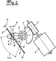
- two stable positions E of the lever 1 are observed, namely a first stable end position E as in the Fig. 2 is shown and a second stable end position E corresponding to Fig. 3 , Between these two stable end positions E, the lever 1 passes over a predetermined swivel angle range 9, which corresponds to an associated swivel angle ⁇ .
- the pivot angle ⁇ is about 60 ° to 80 °, in particular about 70 °.
- the spring element 5 is designed here as a straight spring wire 5.
- the spring element 5 is clamped at each end points 5 '.
- the straight spring wire 5 may be angled in the region of the end points 5 'by 90 ° in comparison to the plane of the drawing and in associated ones Receiving holes are anchored in a lock housing, not shown.
- the spring element 5 or the straight spring wire 5 according to the invention performs no linear movements, which can be traced back to its fixed clamping at the two associated end points 5 '.
- the spring element 5 passes through the lever 1 in the region of an opening 8.
- the opening allows 8 pivotal movements of the lever 1 relative to the spring 5 and the spring element 5 in the predetermined pivoting angle range 9.
- two substantially opposing and spaced bearing surfaces 6, 7 for the spring element 5 are realized.
- the two contact surfaces 6, 7 have a distance A from each other, which is a multiple of a diameter D of the spring element 5.
- the spring element or the straight spring wire 5 is designed predominantly cylindrical with a circular cross section.
- the distance A between the two contact surfaces 6, 7 moves within the scope of the embodiment in the range of about three times the diameter. That is, it applies: A ⁇ 3 D ,
- the lever or pivot lever 1 in the Fig. 1 to 3 perform pivoting movements taking into account the predetermined pivoting angle range 9 and the associated pivot angle ⁇ .
- the one bearing surface 7 is formed as a deflection 7.
- the other bearing surface 6 is a stop surface 6.
- the stop surface 6 moves only to define the respective stable position E as shown in the Fig. 2 and 3 That is, as soon as the stop surface 6 moves against the spring element 5, the stable position E is corresponding to the Fig. 2 or according to the Fig. 3 taken by the lever or pivot lever 1.
- the deflection surface 7 ensures that the spring element 5 is deflected on one side, ie in one direction, between these two stable positions E previously referred to. In the present case experiences the spring element or the straight spring wire 5 through the deflection surface 7 a deflection radially outwardly compared to the axis of rotation 3 of the pivot lever 1. This is indicated by an arrow in Fig. 1 indicated and results from the dashed or dash-dotted lines undeflected course of the spring element or the straight spring wire in the Fig. 1 to 5 ,
- the spring element 5 in the region of a tilting point K after Fig. 1 a maximum unilateral deflection experiences radially outward.
- the tilting point K is located between the two stable positions E Fig. 2 and Fig. 3 , That is, the corresponding end position positions E.
- the tilting point K is arranged approximately in the center between the two stable positions or between the two end positions E with respect to the predetermined pivot angle range 9.
- the locking system described has, as it were, elastically formed end stops or resilient end stops which exert an effect in the overstroke range Ü.
- elastically formed end stops or resilient end stops which exert an effect in the overstroke range Ü.
- the two contact surfaces 6, 7 in conjunction with the opening 8 in the lever 1 in combination with the spring element 5 for the described positioning of the lever respectively pivot lever provide and can also provide.
- the stop surface 6 is designed predominantly circular, whereas the deflection 7 a T-shaped character with each have two arcuate end portions 7 'and a predominantly straight central portion 7 "As long as the lever 1 moves in the predetermined pivoting angle range 9, provides mainly the slightly curved central region 7" for the radially outwardly directed deflection of the spring element 5.
- the arcuate curved end portions 7 'of the deflection surface 7 predominantly used when the lever 1 moves in the respective Matterhub Schle Ü.
Landscapes
- Lock And Its Accessories (AREA)
Description
Die Erfindung betrifft ein Schließsystem, insbesondere ein Kraftfahrzeugtürschloss, mit wenigstens einem Hebel, und mit einer Positionssicherungseinheit für den Hebel, wobei die Positionssicherungseinheit wenigstens ein Federelement aufweist und zur Definition zumindest einer stabilen Position des Hebels eingerichtet ist, wobei das Federelement den Hebel im Bereich einer Öffnung durchgreift, wobei die Öffnung Schwenkbewegungen des Hebels gegenüber dem Federelement in einem vorgegebenen Schwenkwinkelbereich zulässt und die Öffnung im Hebel zwei sich im Wesentlichen gegenüberliegende sowie beabstandete Anlageflächen für das Federelement aufweist und die Anlageflächen einen Abstand zueinander besitzen, welcher ein Mehrfaches eines Durchmessers des Federelementes beträgt. Bei einem Schließsystem entsprechend der
Im Rahmen der
Im Stand der Technik wird durchweg so vorgegangen, dass das Federelement bei Einnahme der zumindest einen stabilen Position respektive beim Positionswechsel mehr oder minder ausgeprägte Bewegungen vollführt. Tatsächlich beobachtet man im Rahmen der
Aus der Druckschrift
Die beschriebenen rotativen und/oder linearen Bewegungen des Federelementes werden ergänzend zu den ohnehin obligatorischen und elastischen Verformungen des Federelementes beobachtet und treten hinzu. Als Folge hiervon können sich bei Intensivem und langfristigen Gebrauch Ermüdungsprobleme des Federelementes einstellen bzw. besteht die Gefahr, dass das Federelement die gewünschte Funktion nicht oder nicht mehr vollständig ausfüllt. Das heißt, auf langen Zeitskalen ist im Stand der Technik unter Umständen die Funktionssicherheit gefährdet. Hier will die Erfindung insgesamt Abhilfe schaffen.The described rotary and / or linear movements of the spring element are observed in addition to the already obligatory and elastic deformations of the spring element and occur. As a result, fatigue problems of the spring element may occur during intensive and long-term use, or there is a risk that the spring element does not or no longer completely fills the desired function. That is, on long time scales in the state of the art under certain circumstances, the functional safety is at risk. Here, the invention aims to provide a total remedy.
Zur Lösung dieser technischen Problemstellung weist ein Schließsystem die Merkmale des ersten Anspruchs auf.To solve this technical problem, a locking system has the features of the first claim.
Nach vorteilhafter Ausgestaltung ist das Federelement überwiegend aus einem geraden Federdraht hergestellt. Außerdem wird meistens so vorgegangen dass das Federelement jeweils an Endpunkten eingespannt wird. Ein zwischen den beiden Endpunkten verbleibender Zwischenbereich kann dagegen elastisch verformt werden, wobei der mit dem Federelement wechselwirkende Hebel für die gewünschten elastischen Verformungen dieses Zwischenbereiches sorgt.According to an advantageous embodiment, the spring element is made predominantly of a straight spring wire. In addition, it is usually the procedure that the spring element is clamped at each endpoints. On the other hand, an intermediate region remaining between the two end points can be elastically deformed, the lever interacting with the spring element providing the desired elastic deformations of this intermediate region.
Im Rahmen der Erfindung kommt also zunächst einmal und überwiegend ein als gerader Federdraht ausgebildetes Federelement zum Einsatz, welches an Endpunkten eingespannt ist. Dadurch werden im Betrieb etwaige Linearbewegungen, Rotationen etc. des Federelementes schon vom Ansatz her nicht zugelassen, so dass die zuvor beschriebenen Ermüdungsprobleme nicht oder nicht mehr auftreten können. Gleichwohl wird die Elastizität der Feder im Rahmen der Erfindung genutzt, um die zumindest eine stabile Position des Hebels darstellen zu können.In the context of the invention, therefore, first and foremost, a spring element designed as a straight spring wire is used which adjoins Endpoints is clamped. As a result, any linear movements, rotations, etc., of the spring element are not permitted in the beginning of operation, so that the previously described fatigue problems can not or no longer occur. However, the elasticity of the spring is used in the invention in order to represent the at least one stable position of the lever can.
Meistens ist die Positionssicherungseinheit bistabil ausgelegt. Das heißt, der Hebel lässt sich in zwei stabile Positionen verschwenken, wobei die beiden jeweils stabilen Positionen durch die Wechselwirkung des Hebels mit dem Federelement jeweils definiert werden. Das geschieht im Detail dadurch, dass die Feder bzw. das Federelement die Öffnung im Hebel durchgreift und die Öffnung so ausgelegt ist, dass die beschriebenen Schwenkbewegungen des Hebels zugelassen werden. Meistens lässt sich der Hebel von einer stabilen Position in die andere stabile Position verschwenken, wobei der Winkelbereich zwischen diesen beiden stabilen Positionen den vorgegebenen SchwenkwinkelBereich darstellt,In most cases, the position assurance unit is designed bistable. That is, the lever can be pivoted into two stable positions, wherein the two respective stable positions are defined by the interaction of the lever with the spring element respectively. This is done in detail by the fact that the spring or the spring element engages through the opening in the lever and the opening is designed so that the described pivoting movements of the lever are allowed. In most cases, the lever can be pivoted from one stable position to the other stable position, wherein the angular range between these two stable positions represents the predetermined swivel angle range,
Um dies im Detail zu erreichen, verfügt die Öffnung im Hebel über zwei sich im Wesentlichen gegenüberliegende sowie beabstandete Anlageflächen für das Federelement. Um die Schwenkbarkelt des Hebels gegenüber dem ihn durchgreifenden Federelement unter Berücksichtigung des vorgegebenen Schwenkwinkelbereiches zu ermöglichen, verfügen die Antageflächen
über einen Abstand zueinander, welcher ein Mehrfaches eines Durchmessers des Federelementes beträgt. Wie bereits erläutert, ist das Federelement überwiegend als gerader Federdraht ausgebildet bzw. überwiegend aus einem solchen geraden Federdraht hergestellt. Der gerade Federdraht verfügt typischerweise über eine zylindrische Gestalt mit Kreisquerschnitt und zugehörigem Durchmesser. Der Durchmesser des Federelementes passt meistens zweimal oder sogar dreimal nebeneinander zwischen die beiden die Öffnung im Hebel definierenden Anlageflächen.To achieve this in detail, the opening in the lever has two substantially opposite and spaced contact surfaces for the spring element. In order to allow the Schwenkbarkelt of the lever against the spring element penetrating him taking into account the predetermined pivoting angle range, have the antireflective surfaces
over a distance to each other, which is a multiple of a diameter of the spring element. As already explained, the spring element is predominantly designed as a straight spring wire or produced predominantly from such a straight spring wire. The straight spring wire typically has a cylindrical shape with a circular cross-section and associated diameter. The diameter of the spring element fits usually two or even three times side by side between the two defining the opening in the lever contact surfaces.
Anders ausgedrückt, beträgt der Abstand zwischen den beiden besagten Anlageflächen beispielsweise des Zweifache, das Dreifache etc. des Durchmessers des Federelementes. Dabei sind selbstverständlich auch Dezimalvielfache denkbar und werden umfasst, z. B. derart, dass der Abstand das 1,5 fache, das 2,5 fache des Durchmessers des Federelementes beträgt.In other words, the distance between the two said contact surfaces, for example, twice, three times, etc., the diameter of the spring element. Of course, decimal multiples are conceivable and are included, for. B. such that the distance is 1.5 times, 2.5 times the diameter of the spring element.
Die beiden die Öffnung im Hebel definierenden Anlageflächen sind unterschiedlich ausgelegt. Tatsächlich handelt es sich bei den Anlageflächen einerseits um eine Auslenkfläche und andererseits eine Anschlagfläche. Die Auslenkfläche liegt während sämtlicher Schwenkbewegungen des Hebels an dem Federelement an. Dagegen fährt die Anschlagfläche lediglich zur Definition der stabilen Position gegen das Federelement.The two defining the opening in the lever contact surfaces are designed differently. In fact, the contact surfaces are, on the one hand, a deflection surface and, on the other hand, a stop surface. The deflection surface abuts against the spring element during all pivoting movements of the lever. In contrast, the stop surface moves only to define the stable position against the spring element.
Aufgrund dieser Auslegung erklärt sich, dass die Auslenkfläche das Federelement bzw. den geraden Federdraht zwischen den beiden stabilen Positionen einseitig, das heißt in einer Richtung, auslenkt. Denn der Federdraht bzw. das Federelement ist an seinen Endpunkten jeweils eingespannt, so dass die das Federelement beaufschlagende Auslenkfläche für die beschriebene elastische Verformung des Federelementes in einer Richtung, das heißt einseitig, sorgt. In der jeweils stabilen Position erfährt das Federelement jedoch im Wesentlichen keine Auslenkung. Das heißt, in dieser stabilen Position beaufschlagt die Auslenkfläche das Federelement nicht oder praktisch nicht.Due to this interpretation explains that the deflection deflects the spring element or the straight spring wire between the two stable positions on one side, that is in one direction. Because the spring wire or the spring element is clamped at its end points in each case, so that the spring element acting on the deflection surface for the described elastic deformation of the spring element in one direction, that is one-sided, provides. In the respectively stable position, however, the spring element undergoes substantially no deflection. That is, in this stable position, the deflection surface does not or practically does not act on the spring element.
Auf diese Weise stellt sich ein Kipppunkt des Hebels zwischen den beiden stabilen Positionen ein. Im Bereich dieses Kipppunktes erfährt das Federelement eine maximale einseitige Auslenkung, und zwar mit Hilfe der Auslenkfläche.In this way, a tilting point of the lever between the two stable positions. In the region of this tilting point, the spring element undergoes a maximum unilateral deflection, with the aid of the deflection surface.
Tatsächlich korrespondiert der Kipppunkt dazu, dass das Federelement durch die maximale Auslenkung eine maximal den Hebel entgegenwirkende Kraft erzeugt, so dass der Hebel jeweils bestrebt ist, in die eine oder andere Richtung im Vergleich zum Kipppunkt auszuweichen. Denn in beiden Richtungen beidseitig des Kipppunktes sind die von dem Federelement aufgebauten Gegenkräfte kleiner ausgelegt als im Bereich des Kipppunktes. Hierdurch erklärt sich, dass die Positionssicherungseinheit bistabil ausgelegt ist, weil die beiden jeweils stabilen Positionen dazu korrespondieren, dass das Federelement keine oder allenfalls eine geringe Gegenkraft auf den Hebel ausübt und dieser folgerichtig die betreffende stabile Position vorteilhaft einnimmt.In fact, the tilting point corresponds to the fact that the spring element generates a maximum of the lever counteracting force by the maximum deflection, so that the lever is always anxious to avoid in one or the other direction compared to the tipping point. Because in both directions on both sides of the tipping point, the opposing forces built up by the spring element are designed to be smaller than in the region of the tipping point. This explains why the position assurance unit is designed to be bistable, because the two stable positions correspond to the fact that the spring element exerts no or at most a small counterforce on the lever and this logically assumes the relevant stable position advantageous.
Im Allgemeinen ist der Kipppunkt mittig zwischen den beiden stabilen Positionen angeordnet. Diese mittige Position stellt sich im Vergleich zu dem vorgegebenen Schwenkwinkelbereich dar. Neben diesem vorgegebenen Schwenkwinkelbereich mit jeweils endseitigen stabilen Positionen und mittigem Kipppunkt wird jeweils jenseits der stabilen Position ein Überhubbereich beobachtet. In diesem Überhubbereich erfährt das Federelement eine zweiseitige Auslenkung. Das heißt, das Federelement wird im Überhubbereich in zwei Richtungen ausgelenkt, und zwar radial auswärts und radial einwärts im Vergleich zu einem Drehpunkt bzw. einer Drehachse des auf der betreffenden Achse gelagerten Hebels respektive Schwenkhebels. Demgegenüber erfährt das Federelement im Kipppunkt und zwischen den beiden stabilen Positionen lediglich eine Auslenkung radial auswärts.In general, the tipping point is centered between the two stable positions. This central position is compared to the predetermined swivel angle range. In addition to this predetermined swivel angle range with end-side stable positions and central tilting point, an overstroke range is observed beyond the stable position. In this Überhubbereich the spring element undergoes a two-sided deflection. That is, the spring element is deflected in the overstroke in two directions, namely radially outwardly and radially inwardly compared to a pivot point or a rotation axis of the lever mounted on the relevant axis respectively pivot lever. In contrast, the spring element experiences in the tipping point and between the two stable positions only a deflection radially outward.
Die Auslenkung des Federelementes im Überhubbereich sowohl radial auswärts als auch radial einwärts führt dazu, dass das Federelement in diesem Überhubbereich einen angenähert S-bogenförmigen Verlauf beschreibt. Als Folge hiervon baut das Federelement besonders starke und auf den Hebel einwirkende Gegenkräfte auf, welche den Hebel in Richtung auf die stabile Position zurück beaufschlagen. Die beiden Überhubbereiche jeweils jenseits der stabilen Position stellen also gleichsam federnde Endanschläge dar, so dass der Hebel ausdrücklich nicht gegen etwaige mechanisch feste Endanschläge fährt.. Vielmehr sind die Endanschläge - wenn man so will - federnd ausgelegt, liegen nämlich in Gestalt der jeweils beschriebenen Überhubbereiche vor. Diese Überhubbereiche korrespondieren zu einer zweiseitigen Auslenkung des Federelementes und damit dazu, dass der im Überhubbereich jeweils befindliche Hebel eine ihn beaufschlagende Kraft in Richtung auf die stabile Position erfährt.The deflection of the spring element in the overstroke range both radially outwardly and radially inwardly causes the spring element to describe an approximately S-curved course in this overstroke region. As a result, the spring element builds up particularly strong and acting on the lever counter forces, which the lever in the direction of the stable Apply position back. The two Überhubbereiche each beyond the stable position thus represent as it are resilient end stops, so that the lever is not expressly against any mechanically fixed stops .. Rather, the end stops - if you will - designed resilient, namely, are in the form of each described Überhubbereiche in front. These overstroke ranges correspond to a two-sided deflection of the spring element and thus to the fact that the lever located in the overstroke region experiences a force acting on it in the direction of the stable position.
Eine derartige Auslegung ist besonders vorteilhaft vor dem Hintergrund, dass es sich bei dem Hebel typischerweise um einen auf der bereits angesprochenen Achse gelagerten Schwenkhebel handelt. Außerdem ist der Hebel meistens mit einem motorischen Antrieb ausgerüstet, welcher für eine gewisse Selbsthemmung des Hebels sorgt. Das heißt, die von dem Federelement aufgebauten Gegenkräfte unterstützen eine motorische Bewegung des Hebels in Richtung jeweils auf die stabile Position bzw. wirken einer motorischen Bewegung des Hebels über die stabile Position hinaus entgegen. Sobald also der motorische Antrieb den Hebel über die stabile Position hinaus beaufschlagt, sorgen die dann im dazu gehörigen Überhubbereich entstehenden Gegenkräfte des Federelementes dafür, dass der motorische Antrieb und mit ihm der Hebel gleichsam zurückgedreht werden. Hierdurch erklärt sich die Funktion der solchermaßen realisierten elastischen Endanschläge.Such a design is particularly advantageous in the light of the fact that the lever is typically a pivoting lever mounted on the axis already mentioned. In addition, the lever is usually equipped with a motor drive, which ensures a certain self-locking of the lever. That is, the opposing forces built up by the spring element assist in a motorized movement of the lever in the direction towards the stable position or counteract a motorized movement of the lever beyond the stable position. Thus, as soon as the motor drive acts on the lever beyond the stable position, the opposing forces of the spring element which then arise in the associated overstroke range ensure that the motor drive and with it the lever are, as it were, turned back. This explains the function of the thus realized elastic end stops.
Auf diese Weise kann das erfindungsgemäße Schließsystem besonders vorteilhaft zur Realisierung eines Schneckenantriebes eingesetzt werden. Das heißt, der Hebel inklusive motorischem Antrieb fungiert vorteilhaft als Schneckenantrieb, der beispielsweise in Verbindung mit einem Verriegelungshebel, einem Diebstahlsicherungshebel etc. eines Kraftfahrzeugtürschlosses zum Einsatz kommen kann. Dabei sind ausdrücklich mechanische Endanschläge nicht erforderlich, weil das erfindungsgemäße Schließsystem mit alternativen federnden Endanschlägen ausgerüstet ist. Das steigert die Lebensdauer und Funktionssicherheit, zumal Ermüdungserscheinungen des erfindungsgemäßen Federelementes - im Gegensatz zum Stand der Technik - nicht mehr beobachtet werden. Hierin sind die wesentlichen Vorteile zu sehen.In this way, the locking system according to the invention can be used particularly advantageously for the realization of a worm drive. That is, the lever including the motor drive advantageously acts as a worm drive, which can be used, for example, in conjunction with a locking lever, an anti-theft lever, etc. of a motor vehicle door lock. In this case, mechanical end stops are not required because the locking system according to the invention is equipped with alternative resilient end stops. This increases the life and reliability, especially since fatigue of the spring element according to the invention - in contrast to the prior art - are no longer observed. Here are the main benefits.
Im Folgenden wird die Erfindung anhand einer lediglich ein Ausführungsbeispiel darstellenden Zeichnung näher erläutert; es zeigen:
- Fig. 1
bis 3 - das erfindungsgemäße Schließsystem in verschiedenen Funktionsstellungen unter Berücksichtigung eines vorgege-benen Schwenkwinkelbereiches und
- Fig. 4 und 5
- das Schließsystem nach den
Fig. 1 in jeweils einem Überhubbereich bzw. die Funktionsweise der federnden Endanschläge.bis 3
- Fig. 1 to 3
- the locking system according to the invention in different functional positions, taking into account a pre-given pivoting angle range and
- 4 and 5
- the locking system after the
Fig. 1 to 3 in each case an overstroke or the operation of the resilient end stops.
In den Figuren ist ein Schließsystem dargestellt, vorliegend ausschnittsweise ein Kraftfahrzeugtürschloss. Von diesem Kraftfahrzeugtürschloss ist lediglich ein Schneckenrad 1 gezeigt, welches mit Hilfe einer Schnecke 2 in Rotationen um eine Achse 3 versetzt wird. Zu diesem Zweck ist das Schneckenrad 2 an eine ausgangsseitige Abtriebswelle eines motorischen Antriebes 4 angeschlossen. Der motorische Antrieb 4 mag von einer nicht dargestellten Steuereinheit beaufschlagt werden.In the figures, a locking system is shown, in this case partially a motor vehicle door lock. From this motor vehicle door lock only a
Außerdem kann das Schneckenrad 1 auf einen nicht explizit dargestellten Zentralverriegelungshebel, einen Diebstahlsicherungshebel etc. arbeiten bzw. mit einem derartigen Hebel zusammenfallen.In addition, the
Die grundsätzliche Funktionsweise mag dabei so ausgelegt sein, wie dies in der
Bei dem Schneckenrad 1 bzw. dem an dieser Stelle realisierten Hebel 1 handelt es sich - wie bereits gesagt - um einen Hebel bzw. Schwenkhebel 1, der auf der Achse 3 gelagert ist und um diese Achse 3 Schwenkbewegungen vollführen kann. Die Schwenkbewegungen des Hebels 1 werden begrenzt, und zwar durch eine Positionssicherungseinheit 5, 6, 7, 8 für den Hebel 1. Die Positionssicherungseinheit 5, 6, 7, 8 weist wenigstens ein Federelement 5 auf. Außerdem ist die Positionssicherungseinheit 5, 6, 7, 8 zur Definition zumindest einer stabilen Position I des Hebels 1 eingerichtet.The
Im Rahmen des Ausführungsbeispiels werden zwei stabile Positionen E des Hebels 1 beobachtet, nämlich eine erste stabile Endposition E wie sie in der
Das Federelement 5 ist vorliegend als gerader Federdraht 5 ausgelegt. Außerdem ist das Federelement 5 jeweils an Endpunkten 5' eingespannt. Zu diesem Zweck mag der gerade Federdraht 5 im Bereich der Endpunkte 5' um jeweils 90° im Vergleich zu der Zeichenebene abgewinkelt sein und in zugehörige Aufnahmebohrungen in einem nicht dargestellten Schlossgehäuse verankert werden. Jedenfalls vollführt das Federelement 5 bzw. der gerade Federdraht 5 erfindungsgemäß keine Linearbewegungen, was sich auf seine feste Einspannung an den beiden zugehörigen Endpunkten 5' zurückführen lässt.The
Man erkennt, dass das Federelement 5 den Hebel 1 im Bereich einer Öffnung 8 durchgreift. Dabei lässt die Öffnung 8 Schwenkbewegungen des Hebels 1 gegenüber der Feder 5 bzw. dem Federelement 5 in dem vorgegebenen Schwenkwinkelbereich 9 zu. Um dies im Detail zu erreichen, sind im Bereich der Öffnung 8 zwei sich im Wesentlichen gegenüberliegende sowie beabstandete Anlagenfläche 6, 7 für das Federelement 5 realisiert.It can be seen that the
Die beiden Anlageflächen 6, 7 weisen einen Abstand A zueinander auf, welcher ein Mehrfaches eines Durchmessers D des Federelementes 5 beträgt. Tatsächlich ist das Federelement bzw. der gerade Federdraht 5 überwiegend zylindrisch mit Kreisquerschnitt ausgelegt. Der Abstand A zwischen den beiden Anlageflächen 6, 7 bewegt sich im Rahmen des Ausführungsbeispiels im Bereich von etwa dem Dreifachen des Durchmessers. Das heißt, es gilt: ![]()
![]()
Auf diese Weise kann der Hebel bzw. Schwenkhebel 1 die in den
Die eine Anlagefläche 7 ist als Auslenkfläche 7 ausgebildet. Bei der anderen Anlagefläche 6 handelt es sich demgegenüber um eine Anschlagfläche 6. Beim Vergleich der
Die Auslenkfläche 7 sorgt dafür, dass das Federelement 5 zwischen diesen beiden zuvor bereits in Bezug genommenen stabilen Positionen E einseitig, das heißt in einer Richtung ausgelenkt wird. Vorliegend erfährt das Federelement bzw. der gerade Federdraht 5 durch die Auslenkfläche 7 eine Auslenkung nach radial auswärts im Vergleich zur Drehachse 3 des Schwenkhebels 1. Das ist durch einen Pfeil in
Man erkennt, dass das Federelement 5 im Bereich eines Kipppunktes K nach
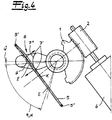
Sobald der Schwenkhebel 1 eine Bewegung jenseits der stabilen Positionen bzw. Endpositionen E erfährt, wie dies in den
Die Auslenkung radial auswärts wird dabei erneut von der Auslenkfläche 7 bewirkt, wohingegen die Anschlagfläche 6 dafür sorgt, dass das Federelement 5 zusätzlich radial einwärts beaufschlagt wird. Als Folge hiervon beschreibt das Federelement im Überhubbereich Ü und auch darüber hinaus einen angenähert S-bogenförmigen Verlauf. Aufgrund dieses S-bogenförmigen Verlaufes des Federelementes 5 werden starke Rückstellkräfte auf den Hebel 1 in Richtung auf die jeweilige Endposition E ausgeübt, welche den Hebel bzw. Schwenkhebel 1 gleichsam in Richtung auf die Endposition E um die Achse 3 zurückverschwenken bzw. in dieser Richtung beaufschlagen. Dabei mögen diese Kräfte so stark sein, dass gegebenenfalls sogar der Antrieb 4 für den Hebel 1 zurückgedreht wird.The deflection radially outward is effected again by the
Als Folge hiervon verfügt das beschriebene Schließsystem gleichsam über elastisch ausgebildete Endanschläge bzw. federnde Endanschläge, die im Überhubbereich Ü Wirkung entfalten. Denn sobald der Hebel 1 in den jeweiligen Überhubbereich Ü jenseits der stabilen Endposition E überführt wird, führen diese Kräfte dazu, dass der Schwenkhebel 1 mit zurückdrehenden Kräften in Folge der S-bogenförmigen Verformung des Federelementes 5 beaufschlagt wird.As a consequence thereof, the locking system described has, as it were, elastically formed end stops or resilient end stops which exert an effect in the overstroke range Ü. For as soon as the
Anhand der vorangestellten Erläuterungen wird deutlich, dass die beiden Anlageflächen 6, 7 in Verbindung mit der Öffnung 8 in dem Hebel 1 in Kombination mit dem Federelement 5 für die beschriebene Positionierung des Hebels respektive Schwenkhebels sorgen und auch sorgen können. Folgerichtig definieren die beiden Anlageflächen 6, 7 in Verbindung mit der Öffnung 8 und dem Federelement 5 die zuvor bereits in Bezug genommene Positionssicherungseinheit 5, 6, 7, 8. Dabei ist die Anschlagfläche 6 überwiegend kreisförmig ausgelegt, wohingegen die Auslenkfläche 7 einen T-förmigen Charakter mit jeweils zwei bogenförmigen Endbereichen 7' und einem überwiegend geraden Mittelabschnitt 7" aufweist. Solange sich der Hebel 1 in dem vorgegebenen Schwenkwinkelbereich 9 bewegt, sorgt überwiegend der leicht gekrümmte Mittelbereich 7" für die nach radial auswärts gerichtete Auslenkung des Federelementes 5. Dagegen kommen die bogenförmig gekrümmten Endbereiche 7' der Auslenkfläche 7 überwiegend dann zum Einsatz, wenn der Hebel 1 in den jeweiligen Überhubbereiche Ü fährt.With reference to the preceding explanations it is clear that the two
Claims (12)
- Locking system, in particular vehicle door lock, with at least one lever (1), and with a position securing unit (5, 6, 7, 8) for the lever (1), wherein the position securing unit (5, 6, 7, 8) has at least one spring element (5) and is configured to define at least one stable position (E) of the lever (1), wherein the spring element (5) reaches through the lever (1) in an area of an opening (8), wherein the opening (8) allows swivel movements of the lever (1) relatively to the spring element (5) in a predetermined swivel angle range (9) and the opening (8) has two contact surfaces (6, 7) for the spring element (5) that are substantially facing each other as well as are spaced, and wherein the contact surfaces (6, 7) have a distance (A) between each other, which amounts to a multiple of a diameter (D) of the spring element (5), characterized in that the contact surfaces (6, 7) are formed on the one hand as displacement surface (7) and on the other hand as stop surface (6), wherein the displacement surface (7) lies against the spring element (5) during all swivel movements of the lever (1), whereas the stop surface (6) run against the spring element (5) only for the defining of the stable position (E).
- Locking system according to claim 1, characterized in that the displacement surface (7) displaces the spring element (5) to one side between two stable positions (E), whereas the spring element (5) is substantially not subject to displacement when being in the respective stable position (E).
- Locking system according to one of the claims 1 or 2, characterized in that the spring element (5) has a maximum displacement to one side in an area of a tilting point (K).
- Locking system according to claim 3, characterized in that the tilting point (K) is arranged centrically compared to the predetermined swivel angle range (9) between the two stable positions (E).
- Locking system according to one of the claims 1 to 4, characterized in that the spring element (5) is subject to a displacement to two sides when being beyond the respective stable position (E), in a over stroke area (Ü).
- Locking system according to claim 5, characterized in that the spring element (5) performs an S-curved run in the over stroke area (0).
- Locking system according to one of the claims 1 to 6, characterized in that the spring element (5) is formed in a linear extending manner.
- Locking system according to claim 7, characterized in that the spring element (5) is mainly made of a straight spring wire (5).
- Locking system according to one of the claims 1 to 8, characterized in that the spring element (5) is mounted at respective end points (5'), whereas an intermediate area between end points (51) is subject to elastic deformation caused by the lever (1).
- Locking system according to one of the claims 1 to 9, characterized in that the lever (1) is formed as a swiveling lever (1) mounted on an axis (3).
- Locking system according to one of the claims 1 to 10, characterized in that the lever (1) has a motor drive (4).
- Locking system according to one of the claims 1 to 11, characterized in that the lever (1) including the drive (4) is formed as a worm drive for as an example a locking lever or a theft protection lever of a vehicle door lock.
Applications Claiming Priority (2)
| Application Number | Priority Date | Filing Date | Title |
|---|---|---|---|
| DE201120005086 DE202011005086U1 (en) | 2011-04-09 | 2011-04-09 | locking system |
| PCT/DE2012/000317 WO2012139544A1 (en) | 2011-04-09 | 2012-03-24 | Locking system |
Publications (2)
| Publication Number | Publication Date |
|---|---|
| EP2697458A1 EP2697458A1 (en) | 2014-02-19 |
| EP2697458B1 true EP2697458B1 (en) | 2017-05-10 |
Family
ID=46124234
Family Applications (1)
| Application Number | Title | Priority Date | Filing Date |
|---|---|---|---|
| EP12721712.3A Active EP2697458B1 (en) | 2011-04-09 | 2012-03-24 | Locking system |
Country Status (8)
| Country | Link |
|---|---|
| US (1) | US9371670B2 (en) |
| EP (1) | EP2697458B1 (en) |
| JP (1) | JP6037143B2 (en) |
| KR (1) | KR101531126B1 (en) |
| CN (1) | CN103597156B (en) |
| CA (1) | CA2832352A1 (en) |
| DE (1) | DE202011005086U1 (en) |
| WO (1) | WO2012139544A1 (en) |
Families Citing this family (4)
| Publication number | Priority date | Publication date | Assignee | Title |
|---|---|---|---|---|
| DE102017105657A1 (en) * | 2017-03-16 | 2018-09-20 | Kiekert Ag | ACTUATOR FOR MOTOR VEHICLE APPLICATIONS |
| DE102017111704A1 (en) | 2017-05-30 | 2018-12-06 | Kiekert Ag | Locking system with rotatable actuator and spring element |
| CN110388142A (en) * | 2018-04-19 | 2019-10-29 | 开开特股份公司 | Automobile door lock |
| DE102018109898A1 (en) * | 2018-04-25 | 2019-10-31 | Kiekert Aktiengesellschaft | Motor vehicle lock |
Family Cites Families (17)
| Publication number | Priority date | Publication date | Assignee | Title |
|---|---|---|---|---|
| FR2267438B1 (en) * | 1974-04-11 | 1976-10-08 | Peugeot & Renault | |
| FR2559827B1 (en) * | 1984-02-17 | 1986-07-04 | Mecanismes Comp Ind De | CLUTCH AND RELEASE DEVICE, PARTICULARLY FOR AN ELECTRIC LOCKING MECHANISM FOR A MOTOR VEHICLE DOOR |
| GB2207698B (en) * | 1987-08-07 | 1990-11-28 | Rockwell Automotive Body Co | Vehicle door latches and locking mechanism |
| JPH02256775A (en) * | 1989-03-29 | 1990-10-17 | Nippondenso Co Ltd | Door lock driving device |
| JPH0643961Y2 (en) * | 1989-05-30 | 1994-11-14 | 市光工業株式会社 | Toggle switch |
| US5267460A (en) * | 1991-11-21 | 1993-12-07 | Supra Products, Inc. | Combination lock |
| JP2999401B2 (en) * | 1995-09-14 | 2000-01-17 | リズム時計工業株式会社 | Rotating decoration mechanism |
| DE19713864C2 (en) | 1997-04-04 | 1999-09-09 | Kiekert Ag | Motor vehicle door lock |
| FR2778197B1 (en) * | 1998-04-30 | 2000-06-23 | Valeo Securite Habitacle | MOTOR VEHICLE DOOR LOCK WITH EMERGENCY CONVICTION |
| FR2816073B1 (en) * | 2000-10-26 | 2003-09-12 | Peugeot Citroen Automobiles Sa | DEVICE FOR CONTROLLING ONE OR MORE MECHANISMS, PARTICULARLY FOR A SUNLOCK OF A MOTOR VEHICLE |
| DE10206813A1 (en) * | 2002-02-19 | 2003-08-28 | Huf Huelsbeck & Fuerst Gmbh | Lock for motor vehicle doors, flaps or similar, has actuating element with actuating surface increasing radially in direction of rotation, reverse motion blocking section |
| GB0217665D0 (en) * | 2002-07-31 | 2002-09-11 | Arvinmeritor Light Vehicle Sys | Actuator assembly |
| US7261338B2 (en) * | 2004-08-09 | 2007-08-28 | Meritor Technology Inc. | Single actuator power close latch mechanism with failsafe |
| WO2009030046A1 (en) * | 2007-09-05 | 2009-03-12 | Magna Closures Inc. | Door latch with child lock and double lock |
| CN201129086Y (en) * | 2007-11-02 | 2008-10-08 | 杨海平 | Lock body of motor vehicle lockset |
| DE102007055413B4 (en) | 2007-11-19 | 2017-06-22 | Kiekert Ag | Locking system with multi-stable component-spring element device |
| DE102008011545A1 (en) | 2008-02-28 | 2009-09-03 | Kiekert Ag | Motor vehicle door lock |
-
2011
- 2011-04-09 DE DE201120005086 patent/DE202011005086U1/en not_active Expired - Lifetime
-
2012
- 2012-03-24 US US14/110,246 patent/US9371670B2/en active Active
- 2012-03-24 CA CA 2832352 patent/CA2832352A1/en not_active Abandoned
- 2012-03-24 CN CN201280028155.5A patent/CN103597156B/en active Active
- 2012-03-24 KR KR1020137029368A patent/KR101531126B1/en active IP Right Grant
- 2012-03-24 WO PCT/DE2012/000317 patent/WO2012139544A1/en active Application Filing
- 2012-03-24 JP JP2014502988A patent/JP6037143B2/en active Active
- 2012-03-24 EP EP12721712.3A patent/EP2697458B1/en active Active
Also Published As
| Publication number | Publication date |
|---|---|
| JP6037143B2 (en) | 2016-11-30 |
| JP2014513220A (en) | 2014-05-29 |
| US20140091580A1 (en) | 2014-04-03 |
| CA2832352A1 (en) | 2012-10-18 |
| CN103597156A (en) | 2014-02-19 |
| DE202011005086U1 (en) | 2014-06-06 |
| EP2697458A1 (en) | 2014-02-19 |
| US9371670B2 (en) | 2016-06-21 |
| WO2012139544A1 (en) | 2012-10-18 |
| KR101531126B1 (en) | 2015-06-23 |
| KR20130140168A (en) | 2013-12-23 |
| CN103597156B (en) | 2016-01-20 |
Similar Documents
| Publication | Publication Date | Title |
|---|---|---|
| EP1659298B1 (en) | Linear drive | |
| EP1963600B1 (en) | Bowden cable arrangement for a motor vehicle door lock | |
| EP2836417A1 (en) | Steering gear | |
| EP3027830B1 (en) | Motor vehicle door lock | |
| EP2697458B1 (en) | Locking system | |
| DE102009016139A1 (en) | elastomer joint | |
| DE202005007923U1 (en) | Steering gear e.g. for toothed rack steering in vehicles, has housing with rack along axle can be adjusted and auxiliary support is at axial end of housing with auxiliary support limits bend of rack | |
| EP2734406A2 (en) | Adjusting device for a motor vehicle seat, comprising at least one stop | |
| DE102015201649A1 (en) | connecting element | |
| EP1879758B1 (en) | Split electromechanical motor vehicle stabiliser with locking device and method for roll stabilisation when the active motor vehicle stabiliser fails or is switched off | |
| EP2320100B1 (en) | Traction-pressure rod | |
| DE102009006423B4 (en) | gripping device | |
| WO2018204956A1 (en) | Furniture drive | |
| EP2044341B1 (en) | Safety nut | |
| EP3643562B1 (en) | Vehicle seat element for a vehicle seat with a residual spring path adjustment device | |
| DE69102559T2 (en) | Hinge with integrated hold-open device for vehicle doors or other sashes. | |
| DE102017214199B4 (en) | Arrangement and method for fastening a tailpipe cover | |
| DE102012021702A1 (en) | Locking device for a vehicle component and vehicle seat | |
| WO2017059836A1 (en) | Motor-vehicle door lock having a motion damper | |
| EP4004314B1 (en) | Drive unit for motor-vehicle applications | |
| DE102008036647A1 (en) | Wobble joint fitting for a vehicle seat comprises a spring having a support region which divides the spring into two regions | |
| WO2021083452A1 (en) | Motor vehicle clip connection element | |
| DE112021002299T5 (en) | STEERING COLUMN OF A VEHICLE | |
| EP3348773B1 (en) | Device for opening, closing and locking lamellae of a lamella construction | |
| WO2020200362A1 (en) | Motor vehicle door lock |
Legal Events
| Date | Code | Title | Description |
|---|---|---|---|
| PUAI | Public reference made under article 153(3) epc to a published international application that has entered the european phase |
Free format text: ORIGINAL CODE: 0009012 |
|
| 17P | Request for examination filed |
Effective date: 20131017 |
|
| AK | Designated contracting states |
Kind code of ref document: A1 Designated state(s): AL AT BE BG CH CY CZ DE DK EE ES FI FR GB GR HR HU IE IS IT LI LT LU LV MC MK MT NL NO PL PT RO RS SE SI SK SM TR |
|
| RIN1 | Information on inventor provided before grant (corrected) |
Inventor name: SCHOENENBERG, THOMAS Inventor name: WAHMANN, HENDRIK |
|
| DAX | Request for extension of the european patent (deleted) | ||
| REG | Reference to a national code |
Ref country code: DE Ref legal event code: R079 Ref document number: 502012010321 Country of ref document: DE Free format text: PREVIOUS MAIN CLASS: E05B0015040000 Ipc: E05B0081160000 |
|
| GRAP | Despatch of communication of intention to grant a patent |
Free format text: ORIGINAL CODE: EPIDOSNIGR1 |
|
| RIC1 | Information provided on ipc code assigned before grant |
Ipc: E05B 83/36 20140101ALI20161121BHEP Ipc: E05B 81/34 20140101ALI20161121BHEP Ipc: E05B 81/16 20140101AFI20161121BHEP Ipc: E05B 81/36 20140101ALI20161121BHEP Ipc: E05B 81/06 20140101ALN20161121BHEP Ipc: E05B 81/30 20140101ALI20161121BHEP Ipc: E05B 15/04 20060101ALI20161121BHEP |
|
| INTG | Intention to grant announced |
Effective date: 20161214 |
|
| GRAS | Grant fee paid |
Free format text: ORIGINAL CODE: EPIDOSNIGR3 |
|
| GRAA | (expected) grant |
Free format text: ORIGINAL CODE: 0009210 |
|
| AK | Designated contracting states |
Kind code of ref document: B1 Designated state(s): AL AT BE BG CH CY CZ DE DK EE ES FI FR GB GR HR HU IE IS IT LI LT LU LV MC MK MT NL NO PL PT RO RS SE SI SK SM TR |
|
| REG | Reference to a national code |
Ref country code: GB Ref legal event code: FG4D Free format text: NOT ENGLISH |
|
| REG | Reference to a national code |
Ref country code: AT Ref legal event code: REF Ref document number: 892502 Country of ref document: AT Kind code of ref document: T Effective date: 20170515 Ref country code: CH Ref legal event code: EP |
|
| REG | Reference to a national code |
Ref country code: IE Ref legal event code: FG4D Free format text: LANGUAGE OF EP DOCUMENT: GERMAN |
|
| REG | Reference to a national code |
Ref country code: DE Ref legal event code: R096 Ref document number: 502012010321 Country of ref document: DE |
|
| REG | Reference to a national code |
Ref country code: NL Ref legal event code: MP Effective date: 20170510 |
|
| REG | Reference to a national code |
Ref country code: LT Ref legal event code: MG4D |
|
| PG25 | Lapsed in a contracting state [announced via postgrant information from national office to epo] |
Ref country code: GR Free format text: LAPSE BECAUSE OF FAILURE TO SUBMIT A TRANSLATION OF THE DESCRIPTION OR TO PAY THE FEE WITHIN THE PRESCRIBED TIME-LIMIT Effective date: 20170811 Ref country code: HR Free format text: LAPSE BECAUSE OF FAILURE TO SUBMIT A TRANSLATION OF THE DESCRIPTION OR TO PAY THE FEE WITHIN THE PRESCRIBED TIME-LIMIT Effective date: 20170510 Ref country code: LT Free format text: LAPSE BECAUSE OF FAILURE TO SUBMIT A TRANSLATION OF THE DESCRIPTION OR TO PAY THE FEE WITHIN THE PRESCRIBED TIME-LIMIT Effective date: 20170510 Ref country code: NO Free format text: LAPSE BECAUSE OF FAILURE TO SUBMIT A TRANSLATION OF THE DESCRIPTION OR TO PAY THE FEE WITHIN THE PRESCRIBED TIME-LIMIT Effective date: 20170810 Ref country code: ES Free format text: LAPSE BECAUSE OF FAILURE TO SUBMIT A TRANSLATION OF THE DESCRIPTION OR TO PAY THE FEE WITHIN THE PRESCRIBED TIME-LIMIT Effective date: 20170510 Ref country code: FI Free format text: LAPSE BECAUSE OF FAILURE TO SUBMIT A TRANSLATION OF THE DESCRIPTION OR TO PAY THE FEE WITHIN THE PRESCRIBED TIME-LIMIT Effective date: 20170510 |
|
| PG25 | Lapsed in a contracting state [announced via postgrant information from national office to epo] |
Ref country code: PL Free format text: LAPSE BECAUSE OF FAILURE TO SUBMIT A TRANSLATION OF THE DESCRIPTION OR TO PAY THE FEE WITHIN THE PRESCRIBED TIME-LIMIT Effective date: 20170510 Ref country code: IS Free format text: LAPSE BECAUSE OF FAILURE TO SUBMIT A TRANSLATION OF THE DESCRIPTION OR TO PAY THE FEE WITHIN THE PRESCRIBED TIME-LIMIT Effective date: 20170910 Ref country code: NL Free format text: LAPSE BECAUSE OF FAILURE TO SUBMIT A TRANSLATION OF THE DESCRIPTION OR TO PAY THE FEE WITHIN THE PRESCRIBED TIME-LIMIT Effective date: 20170510 Ref country code: LV Free format text: LAPSE BECAUSE OF FAILURE TO SUBMIT A TRANSLATION OF THE DESCRIPTION OR TO PAY THE FEE WITHIN THE PRESCRIBED TIME-LIMIT Effective date: 20170510 Ref country code: RS Free format text: LAPSE BECAUSE OF FAILURE TO SUBMIT A TRANSLATION OF THE DESCRIPTION OR TO PAY THE FEE WITHIN THE PRESCRIBED TIME-LIMIT Effective date: 20170510 Ref country code: SE Free format text: LAPSE BECAUSE OF FAILURE TO SUBMIT A TRANSLATION OF THE DESCRIPTION OR TO PAY THE FEE WITHIN THE PRESCRIBED TIME-LIMIT Effective date: 20170510 Ref country code: BG Free format text: LAPSE BECAUSE OF FAILURE TO SUBMIT A TRANSLATION OF THE DESCRIPTION OR TO PAY THE FEE WITHIN THE PRESCRIBED TIME-LIMIT Effective date: 20170810 |
|
| PG25 | Lapsed in a contracting state [announced via postgrant information from national office to epo] |
Ref country code: EE Free format text: LAPSE BECAUSE OF FAILURE TO SUBMIT A TRANSLATION OF THE DESCRIPTION OR TO PAY THE FEE WITHIN THE PRESCRIBED TIME-LIMIT Effective date: 20170510 Ref country code: DK Free format text: LAPSE BECAUSE OF FAILURE TO SUBMIT A TRANSLATION OF THE DESCRIPTION OR TO PAY THE FEE WITHIN THE PRESCRIBED TIME-LIMIT Effective date: 20170510 Ref country code: SK Free format text: LAPSE BECAUSE OF FAILURE TO SUBMIT A TRANSLATION OF THE DESCRIPTION OR TO PAY THE FEE WITHIN THE PRESCRIBED TIME-LIMIT Effective date: 20170510 Ref country code: RO Free format text: LAPSE BECAUSE OF FAILURE TO SUBMIT A TRANSLATION OF THE DESCRIPTION OR TO PAY THE FEE WITHIN THE PRESCRIBED TIME-LIMIT Effective date: 20170510 |
|
| REG | Reference to a national code |
Ref country code: DE Ref legal event code: R097 Ref document number: 502012010321 Country of ref document: DE |
|
| PG25 | Lapsed in a contracting state [announced via postgrant information from national office to epo] |
Ref country code: IT Free format text: LAPSE BECAUSE OF FAILURE TO SUBMIT A TRANSLATION OF THE DESCRIPTION OR TO PAY THE FEE WITHIN THE PRESCRIBED TIME-LIMIT Effective date: 20170510 Ref country code: SM Free format text: LAPSE BECAUSE OF FAILURE TO SUBMIT A TRANSLATION OF THE DESCRIPTION OR TO PAY THE FEE WITHIN THE PRESCRIBED TIME-LIMIT Effective date: 20170510 |
|
| PLBE | No opposition filed within time limit |
Free format text: ORIGINAL CODE: 0009261 |
|
| STAA | Information on the status of an ep patent application or granted ep patent |
Free format text: STATUS: NO OPPOSITION FILED WITHIN TIME LIMIT |
|
| REG | Reference to a national code |
Ref country code: FR Ref legal event code: PLFP Year of fee payment: 7 |
|
| 26N | No opposition filed |
Effective date: 20180213 |
|
| PG25 | Lapsed in a contracting state [announced via postgrant information from national office to epo] |
Ref country code: SI Free format text: LAPSE BECAUSE OF FAILURE TO SUBMIT A TRANSLATION OF THE DESCRIPTION OR TO PAY THE FEE WITHIN THE PRESCRIBED TIME-LIMIT Effective date: 20170510 |
|
| PG25 | Lapsed in a contracting state [announced via postgrant information from national office to epo] |
Ref country code: MT Free format text: LAPSE BECAUSE OF FAILURE TO SUBMIT A TRANSLATION OF THE DESCRIPTION OR TO PAY THE FEE WITHIN THE PRESCRIBED TIME-LIMIT Effective date: 20170510 |
|
| REG | Reference to a national code |
Ref country code: CH Ref legal event code: PL |
|
| GBPC | Gb: european patent ceased through non-payment of renewal fee |
Effective date: 20180324 |
|
| PG25 | Lapsed in a contracting state [announced via postgrant information from national office to epo] |
Ref country code: MC Free format text: LAPSE BECAUSE OF FAILURE TO SUBMIT A TRANSLATION OF THE DESCRIPTION OR TO PAY THE FEE WITHIN THE PRESCRIBED TIME-LIMIT Effective date: 20170510 |
|
| REG | Reference to a national code |
Ref country code: BE Ref legal event code: MM Effective date: 20180331 |
|
| REG | Reference to a national code |
Ref country code: IE Ref legal event code: MM4A |
|
| PG25 | Lapsed in a contracting state [announced via postgrant information from national office to epo] |
Ref country code: LU Free format text: LAPSE BECAUSE OF NON-PAYMENT OF DUE FEES Effective date: 20180324 |
|
| PG25 | Lapsed in a contracting state [announced via postgrant information from national office to epo] |
Ref country code: IE Free format text: LAPSE BECAUSE OF NON-PAYMENT OF DUE FEES Effective date: 20180324 |
|
| PG25 | Lapsed in a contracting state [announced via postgrant information from national office to epo] |
Ref country code: CH Free format text: LAPSE BECAUSE OF NON-PAYMENT OF DUE FEES Effective date: 20180331 Ref country code: LI Free format text: LAPSE BECAUSE OF NON-PAYMENT OF DUE FEES Effective date: 20180331 Ref country code: BE Free format text: LAPSE BECAUSE OF NON-PAYMENT OF DUE FEES Effective date: 20180331 Ref country code: GB Free format text: LAPSE BECAUSE OF NON-PAYMENT OF DUE FEES Effective date: 20180324 |
|
| REG | Reference to a national code |
Ref country code: AT Ref legal event code: MM01 Ref document number: 892502 Country of ref document: AT Kind code of ref document: T Effective date: 20180324 |
|
| PG25 | Lapsed in a contracting state [announced via postgrant information from national office to epo] |
Ref country code: AT Free format text: LAPSE BECAUSE OF NON-PAYMENT OF DUE FEES Effective date: 20180324 |
|
| PG25 | Lapsed in a contracting state [announced via postgrant information from national office to epo] |
Ref country code: TR Free format text: LAPSE BECAUSE OF FAILURE TO SUBMIT A TRANSLATION OF THE DESCRIPTION OR TO PAY THE FEE WITHIN THE PRESCRIBED TIME-LIMIT Effective date: 20170510 |
|
| PG25 | Lapsed in a contracting state [announced via postgrant information from national office to epo] |
Ref country code: HU Free format text: LAPSE BECAUSE OF FAILURE TO SUBMIT A TRANSLATION OF THE DESCRIPTION OR TO PAY THE FEE WITHIN THE PRESCRIBED TIME-LIMIT; INVALID AB INITIO Effective date: 20120324 Ref country code: PT Free format text: LAPSE BECAUSE OF FAILURE TO SUBMIT A TRANSLATION OF THE DESCRIPTION OR TO PAY THE FEE WITHIN THE PRESCRIBED TIME-LIMIT Effective date: 20170510 |
|
| PG25 | Lapsed in a contracting state [announced via postgrant information from national office to epo] |
Ref country code: CY Free format text: LAPSE BECAUSE OF FAILURE TO SUBMIT A TRANSLATION OF THE DESCRIPTION OR TO PAY THE FEE WITHIN THE PRESCRIBED TIME-LIMIT Effective date: 20170510 Ref country code: MK Free format text: LAPSE BECAUSE OF NON-PAYMENT OF DUE FEES Effective date: 20170510 |
|
| PG25 | Lapsed in a contracting state [announced via postgrant information from national office to epo] |
Ref country code: AL Free format text: LAPSE BECAUSE OF FAILURE TO SUBMIT A TRANSLATION OF THE DESCRIPTION OR TO PAY THE FEE WITHIN THE PRESCRIBED TIME-LIMIT Effective date: 20170510 |
|
| P01 | Opt-out of the competence of the unified patent court (upc) registered |
Effective date: 20230529 |
|
| PGFP | Annual fee paid to national office [announced via postgrant information from national office to epo] |
Ref country code: DE Payment date: 20240321 Year of fee payment: 13 Ref country code: CZ Payment date: 20240308 Year of fee payment: 13 |
|
| PGFP | Annual fee paid to national office [announced via postgrant information from national office to epo] |
Ref country code: FR Payment date: 20240319 Year of fee payment: 13 |