EP2697447B1 - Method of protecting the end of a multi-tendon cable - Google Patents
Method of protecting the end of a multi-tendon cable Download PDFInfo
- Publication number
- EP2697447B1 EP2697447B1 EP11730736.3A EP11730736A EP2697447B1 EP 2697447 B1 EP2697447 B1 EP 2697447B1 EP 11730736 A EP11730736 A EP 11730736A EP 2697447 B1 EP2697447 B1 EP 2697447B1
- Authority
- EP
- European Patent Office
- Prior art keywords
- chamber
- protective material
- anchor block
- injected
- tendons
- Prior art date
- Legal status (The legal status is an assumption and is not a legal conclusion. Google has not performed a legal analysis and makes no representation as to the accuracy of the status listed.)
- Active
Links
Images



Classifications
-
- B—PERFORMING OPERATIONS; TRANSPORTING
- B29—WORKING OF PLASTICS; WORKING OF SUBSTANCES IN A PLASTIC STATE IN GENERAL
- B29C—SHAPING OR JOINING OF PLASTICS; SHAPING OF MATERIAL IN A PLASTIC STATE, NOT OTHERWISE PROVIDED FOR; AFTER-TREATMENT OF THE SHAPED PRODUCTS, e.g. REPAIRING
- B29C45/00—Injection moulding, i.e. forcing the required volume of moulding material through a nozzle into a closed mould; Apparatus therefor
- B29C45/14—Injection moulding, i.e. forcing the required volume of moulding material through a nozzle into a closed mould; Apparatus therefor incorporating preformed parts or layers, e.g. injection moulding around inserts or for coating articles
- B29C45/14336—Coating a portion of the article, e.g. the edge of the article
- B29C45/14426—Coating the end of wire-like or rod-like or cable-like or blade-like or belt-like articles
-
- E—FIXED CONSTRUCTIONS
- E04—BUILDING
- E04C—STRUCTURAL ELEMENTS; BUILDING MATERIALS
- E04C5/00—Reinforcing elements, e.g. for concrete; Auxiliary elements therefor
- E04C5/08—Members specially adapted to be used in prestressed constructions
- E04C5/12—Anchoring devices
-
- E—FIXED CONSTRUCTIONS
- E04—BUILDING
- E04C—STRUCTURAL ELEMENTS; BUILDING MATERIALS
- E04C5/00—Reinforcing elements, e.g. for concrete; Auxiliary elements therefor
- E04C5/08—Members specially adapted to be used in prestressed constructions
- E04C5/12—Anchoring devices
- E04C5/122—Anchoring devices the tensile members are anchored by wedge-action
Definitions
- the present invention relates to structural cables used in construction works. It applies, in particular, to the anchoring of stay cables or pre-stressing cables.
- Such structural cables are frequently made of a plurality of parallel tendons. Their ends are anchored using blocks in which channels are formed for receiving and blocking individually the tendons, for example by means of split conical jaws.
- the tendons of the cable are made of metal, for example in the form of strands.
- they are often contained in individual sheaths of plastic material which isolate them from the environment and thus protect them from corrosive agents.
- plastic sheath is removed in the anchoring region. It is then necessary to provide particular anti-corrosion protection measures in the anchoring region.
- the volume containing the exposed portions of the tendons is filled with a protective material injected under pressure into the anchoring region.
- the injection step must be carried out with caution so as to avoid any remaining voids in the volume to be filled, since such voids may be the starting point of the corrosion phenomenon for the metal of the tendons, in particular if water leaks in.
- Wax is an interesting example of protective material to be injected in the anchoring region, in view of its properties of adherence, corrosion protection and fatigue behavior.
- the wax is in a solid state at room temperature and becomes liquid when heated. It can thus form a reversible filling, which is useful for allowing inspection of the anchorage.
- injectable protective materials can be used, in particular thick materials, e.g. grease, or hardening materials, e.g. a resin or a polymer.
- the protective material is selected by taking into account the required functionalities for installing and or maintaining the anchorage.
- the volume to be filled with protective material includes a chamber located on the front side of the anchorage and closed by a cover.
- the end portions of the tendons of the cable, protruding from the anchorage, are located in that chamber.
- the rear side of the anchor block does not have a second chamber containing the tendons collectively.
- the ends of the individual sheaths of the tendons are located in the channels of the anchor block, or in extensions of those channels provided on the rear side of the anchor block.
- the injection is performed once the tendons have been installed and tensioned.
- the filling material is injected by an inlet located in a low portion of the anchorage until it flows out by a vent located in a high portion of the anchorage. This minimizes the risk of leaving voids in the volume to be filled.
- the different channels form competing flow paths.
- the head loss in those channels is not uniform because the contents of channels can be different from one channel to another.
- the block has one or more communication channels in addition to the channels containing tendons, the fluid material has a tendency to flow through the communication channels, so that the other channels may remain with voids, thus exposing the metallic tendons.
- the possible presence of debris in a channel when the injection starts also changes the head loss through that channel and causes a risk of incomplete filling. If there are no communication channels and/or if there is a chamber only on the front side of the anchorage, it is also quite difficult to ensure a complete filling of the channels containing the tendons.
- the invention solves this problem with a method according to claim 1.
- the first injection phase makes it possible to ensure that the channels are properly filled. In particular, they can be filled individually by injecting a controlled amount of protective material. Typically, each channel of the anchor block containing a tendon receives protective material in the first injection phase.
- the protective material injected into the channels of the anchor block in the first phase may be a wax or grease.
- the first injection phase comprises, for each channel:
- the bell-shaped cover may have a passage for that tendon. It is then possible to attach the bell-shaped cover to the tendon when the protective material is injected in order to withstand the injection pressure.
- the proposed method is also advantageous in that the protective material injected into the chamber in the second phase can be chosen different from the protective material injected into the channels of the anchor block in the first phase.
- the selection of the protective materials is made as a function of desired functionalities for each part of the anchorage in order to optimize the properties of the anchorage.
- the method is applicable to an anchorage in which the chamber has two parts on the front and rear sides of the anchor block, respectively, connected together by at least one communication channel extending through the anchor block.
- the communication channel is not filled with protective material in the first injection phase. In most cases, no tendon of the cable will be put in such a communication channel.
- the second injection phase may have a common step of injecting protective material into one of the parts of the chamber and, from said one of the parts of the chamber, into another part of the chamber through the at least one communication channel.
- This chamber contains end portions of the plurality of tendons of the cable, and receives protective material e.g. a wax or grease, in the second injection phase.
- first chamber containing tensioned portions of the tendons, formed on the rear side of the anchor block
- second chamber containing the end portions of the tendons, formed on a front side of the anchor block.
- protective material is injected into the first chamber and separately into the second chamber.
- the protective material e.g. a polymer or a resin
- injected into the first chamber can be chosen different from the protective material, e.g. a wax or grease, injected into the second chamber.
- the structural cable shown in figure 1 is made of a plurality of tendons 10 each consisting of a metallic strand 11 contained in an individual plastic sheath 12. Only two tendons 10 are shown in the figures for simplicity of the drawing. Typically, a higher number of tendons, e.g. a few tens of tendons, are used.
- the tendons 10 extend parallel to each other along the prescribed path of the structural cable, e.g. along the inclined path of a stay cable between the deck and a pylon of a bridge, or along the path specified for a pre-stressing cable.
- the structural cable is anchored at both ends.
- the anchoring devices transfer the tensile load of the cable to the structure.
- the plastic sheaths 12 are removed at the ends of the tendons 10, thus exposing the metal of the strands 11.
- the bare parts of the tendons 10 extend through and beyond an anchor block 15 of the anchoring device.
- the anchor block 15 has a number of channels 16 extending between its rear side 17 (towards the running part of the cable where the tendons will be under tension) and its front side 18. Each tendon 10 is received within one of the channels 16 with a blocking member 19.
- each channel 16 designed to receive a tendon 10 has a cylindrical part near the rear side 17 of the anchor block 15, with a diameter slightly larger than that of the strand 11, extended by a conical part which tapers outwardly towards the front side 18 of the anchor block 15.
- the blocking member is in the form of a conical jaw 19 placed in the conical part of the channel 16 to grip the metallic strand 11.
- the jaw 19 has a cylindrical axial bore for receiving the strand, and is made of a plurality of sectors (e.g. three sectors) held together by a ring 20 inserted in an annular groove located near the wide end of the jaw 19.
- the cable To install the cable, its tendons 10 are inserted into their respective channels 16 with the conical jaws 19, the tensile force is applied by holding the strands 11 in their parts projecting from the front face 18 of the anchor block 15, pulling them using an actuator such as a hydraulic jack, and pushing the jaws 19 into the channels 16. When the actuator is deactivated, the jaws 19 block the strands 11 in their channels 16. This tensioning operation can be performed strand by strand, group of strands by group of strands, or collectively for the whole cable.
- a first injection phase is carried out to make sure that these intervals are filled with a substance 100 which will protect the metal from corrosion.
- the substance with which the channels 16 are filled in the first injection phase is a wax or grease.
- it may also be a curing material such as a polymer or a resin.
- the first injection phase can be performed for each channel 16 by using a bell-shaped cover 25 over the inlet of the channel.
- the cover 25 is sealingly applied against the front side 18 of the anchor block 15 using a gasket 26, and its opposite end has an aperture providing a passage for the strand 11.
- a sealing ring 27 is placed around the strand 11 to seal the front end of the cover 25 which is secured in its position by a ring 28 clamped on the free end of the strand 11.
- the protective material 100 is injected in a fluid or soft phase through an inlet 29 provided in the cover 25. Since the volume of the intervals not occupied by the metallic strand and jaw is known with precision, a regulated amount of protective material can be injected into each channel 16 to ensure complete filling of the channel. An injection pump (not shown) is controlled to inject the set amount of protective material 100 inside the cover 25 to completely fill the channel 16.
- the attachment of the bell-shaped cover 25 to the strand 11 ensures that the cover 25 is kept in place at the inlet of the channel 16 while the protective material is injected under pressure to overcome the head loss within the channel 16. It will be noted that other mechanisms can be used to hold the cover in that step, for example attached to the anchor block 15.
- the filling material 100 injected into the channels 16 is allowed to cure (if it is a polymer or resin) or to solidify by cooling (if it is a wax) and the cover 25 is removed from the front side of the anchor block 15. If the filling 100 is a thick material such as grease, no hardening time is needed and the cover may be removed just after the injection. An amount of protective material 100 may or may not remain on the portion of the strand 11 which was contained in the cover 25.
- a second injection phase is carried out to fill the other closed volume(s) of the anchorage with protective material.
- the first chamber 30 on the rear side 17 of the anchor block is delimited radially by a tube 32 through with the tensioned parts of the tendons 10 extend.
- the ends of the plastic sheaths 12 of the tendons are located within the chamber 30.
- the chamber 30 is closed by a sealing device 34, for example a stuffing box arrangement as described in WO 01 /20098 A1 , which isolates the chamber 30 from the outside while leaving passages for the tendons 10.
- the front end of the tube 32 has a flange 33 which forms a bearing surface for the anchor block 15, the flange 33 being applied against the structure equipped with the cable.
- the anchorage may have various other arrangements within the scope of the present invention.
- the injection of the protective material 200 into the first chamber 30 is performed though an inlet which, in the illustrated example, is formed by an opening 35 provided in the anchor block 15, in a low part of the chamber 30.
- the opening 35 is bent to be accessible on a lateral side of the anchor block 15. It may also be straight and accessible on the front side 18 of the anchor block 15.
- a vent 36 is formed in an upper part of the tube 32 to evacuate the air contained in the chamber 30 during the injection step. Once the injection is complete, the vent 36 is closed by a plug 37 ( figure 3 ) and the protective material 200 is allowed to harden or solidify, if needed, prior to closing the inlet opening 35 with another plug 38.
- the second chamber 31 on the front side 18 of the anchor block is delimited by a case 40 shown in figure 4 .
- the case 40 is mounted on the anchor block 15 by means of bolts or other fixing means (not shown).
- a sealing ring 41 is provided between the rear end of the case 40 and the front face 18 of the anchor block to prevent the protective material from leaking when injected.
- the case 40 is dimensioned to contain the bare ends of all the tendons 10 of the cable. Its lower part has an opening 42 for injecting the protective material 300 and its upper part has a vent 43 for evacuating the air when the protective material 300 is injected.
- the protective material 300 injected into the second chamber 31 fills all the remaining voids. When it flows out though the vent 43, the injection is stopped and a plug 45 is placed on the vent 43. The injected protective material 300 is allowed to harden or solidify, if needed, prior to closing the inlet opening 42 with another plug.
- the protective material injected to fill (i) the channels 16, (ii) the chamber 30 at the rear of the anchor block 15 and (iii) the chamber 31 at the front of the anchor block 15 can be selected independently for each volume to be filled, thus permitting an optimization of the anchorage by choosing each material for its properties as desired.
- the chamber 31 located at the front of the anchor block 15 may be opened, by removing the case 40, during the lifetime of the anchorage to enable checking of its proper operation. For this reason, it is typically desirable to use in that chamber 31 a protective material 300 which can be easily removed.
- a wax is an advantageous material for this purpose since it can be melted or at least softened by heating and pumped out. Grease can also be used.
- a flexible material 100 having lubricating properties such as grease or wax, is suitable in view of its good fatigue behavior which enhances the ultimate strength of the tendons.
- the chamber 30 at the rear of the anchor block 15 is potentially exposed to infiltrations of water flowing along the structure or the cable.
- a flexible, sticky and coherent material 200 is often a good choice to best prevent such infiltrations.
- a polymer or a resin is advantageously injected in that part of the anchorage.
- Figure 5 illustrates an alternative embodiment of an anchoring device, for which the second injection phase, i.e. after filling of the channels 16 where the tendons are blocked, is essentially performed in one step.
- the chamber thus filled is made of two parts 50, 51 connected together by one or more communication channels 52.
- the first part 50 is located on the rear side 17 of the anchor block 15 and is functionally similar to the first chamber 30 of the embodiment shown in figures 1-4 , being delimited by a cylindrical tube 32 and a stuffing box-type of sealing device 34.
- the second part 51 is located on the front side 18 of the anchor block 15 and is functionally similar to the second chamber 31 of the embodiment shown in figures 1-4 , being delimited by a case 40.
- the communication channels 52 do not contain tendons and extend through the anchor block 15 parallel to the channels 16 containing the tendons.
- the first injection phase is performed to fill the channels 16 with a protective substance 100 as described with reference to figure 1 .
- the case 40 is assembled on the anchor block 15 and the second injection phase is performed to inject a protective material 400 in the two-part chamber 50-51.
- FIG. 5 is, for example, that of the anchorage of the lower end of an inclined stay cable.
- the lower part of the anchorage is in the lower part of the case an inlet 42 is provided.
- two vents 36, 43 are provided, one (36) in the upper part of the rear part 50 of the chamber and the other (43) in the upper part of the front part 51 of the chamber.
- the level of the fluid material 400 rises.
- the vent 43 it overflows and a plug 45 is put on that vent 43 to continue the injection, thus permitting the protective material 400 to rise further through the communication channels 52 and into the rear part 50 of the chamber.
- the second injection phase is over and a plug is put on the vent 36.
- the protective material 400 is allowed to harden or solidify, if needed, prior to closing the inlet opening 42 with another plug.
- the protective material 400 injected into the chamber 50-51 in the second phase is preferably, though not necessarily, the same as the protective material 100 injected into the channels 16 in the first phase.
- a wax or grease may be injected into the channels 16 and then into the two-part chamber 50-51.
- specifications of a given work can make it preferable to use different filler materials.
- the chamber filled in the second injection phase is located only on the front side of the anchor block 15.
- the plastic sheaths 12 of the tendons 10 then have their end sections inside the channels 16 of the anchor block 15 or in individual extensions of those channels behind the anchor block 15.
- the first injection phase is performed to fill the channels 16 and/or their extensions with the protective material 100.
- the filling is made at least in the parts of the channels 16 and/or their extensions where the metal of the strand is free of plastic sheath.
- the separate injection of the protective material into the channels 16 and/or their extensions ensures a reliable filling irrespective of the variable head losses typically experienced by the injected substance in those channels.
- the second injection phase is carried out to introduce the protective material 300, which is preferably different from the previously injected protective material 100, into the chamber 31 located only on the front side 18 of the anchor block 15 and containing the end portions of the strands 11. This can be performed in the same manner as described with reference to figure 4 .
- the chamber 31 to be filled with protective material is located only on the front side of the anchor block 15
- wax or grease will often be a suitable choice for the protective material both in the channels 16 and in the chamber 31 because of its good fatigue properties (for the channels 16) and because it is relatively easy to remove (for the chamber 31).
- other choices may be suitable or preferable. For instance, water-tightness at the rear of the channels in such an anchorage design can be a concern. For this reason, an adhering filler material such as a polymer or a resin may be used in the channels 16, while a wax or grease is injected into the chamber 31.
- the above-described method of protecting the bare ends of the tendons of a structural cable using two or more injection phases in different parts of the anchoring device is applicable to the installation of a new cable. It is also applicable to the maintenance or repair of an existing cable.
- the protective filler material which was previously located in the different parts of the anchoring device may be removed (for example using a method as described in French patent application No. 11 52557 filed on March 28, 2011 ) prior to injecting one or more new protective material(s) in two or more phases as described above.
Landscapes
- Engineering & Computer Science (AREA)
- Architecture (AREA)
- Civil Engineering (AREA)
- Structural Engineering (AREA)
- Manufacturing & Machinery (AREA)
- Mechanical Engineering (AREA)
- Bridges Or Land Bridges (AREA)
- Piles And Underground Anchors (AREA)
- Processing Of Terminals (AREA)
- Ropes Or Cables (AREA)
Description
- The present invention relates to structural cables used in construction works. It applies, in particular, to the anchoring of stay cables or pre-stressing cables.
- Such structural cables are frequently made of a plurality of parallel tendons. Their ends are anchored using blocks in which channels are formed for receiving and blocking individually the tendons, for example by means of split conical jaws.
- The tendons of the cable are made of metal, for example in the form of strands. In the main part of the cable, they are often contained in individual sheaths of plastic material which isolate them from the environment and thus protect them from corrosive agents. In order to firmly hold a tendon in the anchor block, its plastic sheath is removed in the anchoring region. It is then necessary to provide particular anti-corrosion protection measures in the anchoring region. In general, the volume containing the exposed portions of the tendons is filled with a protective material injected under pressure into the anchoring region.
- The injection step must be carried out with caution so as to avoid any remaining voids in the volume to be filled, since such voids may be the starting point of the corrosion phenomenon for the metal of the tendons, in particular if water leaks in.
- Wax is an interesting example of protective material to be injected in the anchoring region, in view of its properties of adherence, corrosion protection and fatigue behavior. The wax is in a solid state at room temperature and becomes liquid when heated. It can thus form a reversible filling, which is useful for allowing inspection of the anchorage.
- Other injectable protective materials can be used, in particular thick materials, e.g. grease, or hardening materials, e.g. a resin or a polymer.
- For a given construction work, the protective material is selected by taking into account the required functionalities for installing and or maintaining the anchorage.
- The volume to be filled with protective material includes a chamber located on the front side of the anchorage and closed by a cover. The end portions of the tendons of the cable, protruding from the anchorage, are located in that chamber.
- In certain anchorage designs (see, e.g.,
WO 01 /20098 A1 EP 0 323 285 A1 discloses a similar method according to the preamble of claim 1. - In other kinds of anchorage design (see, e.g.,
EP 0 896 108 A2 orEP 1 227 200 A1 ), the rear side of the anchor block does not have a second chamber containing the tendons collectively. The ends of the individual sheaths of the tendons are located in the channels of the anchor block, or in extensions of those channels provided on the rear side of the anchor block. - The injection is performed once the tendons have been installed and tensioned. Conventionally, the filling material is injected by an inlet located in a low portion of the anchorage until it flows out by a vent located in a high portion of the anchorage. This minimizes the risk of leaving voids in the volume to be filled.
- However, that risk is not completely eliminated. When the level of the filling material rises and reaches the anchor block, the different channels form competing flow paths. The head loss in those channels is not uniform because the contents of channels can be different from one channel to another. For example, if the block has one or more communication channels in addition to the channels containing tendons, the fluid material has a tendency to flow through the communication channels, so that the other channels may remain with voids, thus exposing the metallic tendons. The possible presence of debris in a channel when the injection starts also changes the head loss through that channel and causes a risk of incomplete filling. If there are no communication channels and/or if there is a chamber only on the front side of the anchorage, it is also quite difficult to ensure a complete filling of the channels containing the tendons.
- There is thus a need for an improved method of filling the inner volumes of an anchorage system to protect the tendons and other metallic components of the anchorage from corrosion.
- The invention solves this problem with a method according to claim 1.
- The first injection phase makes it possible to ensure that the channels are properly filled. In particular, they can be filled individually by injecting a controlled amount of protective material. Typically, each channel of the anchor block containing a tendon receives protective material in the first injection phase.
- The protective material injected into the channels of the anchor block in the first phase may be a wax or grease.
- In an embodiment, the first injection phase comprises, for each channel:
- sealingly applying a bell-shaped cover on an inlet of the channel;
- injecting protective material inside the bell-shaped cover to force the protective material into the channel; and
- removing the bell-shaped cover.
- For a channel which contains a tendon of the cable, the bell-shaped cover may have a passage for that tendon. It is then possible to attach the bell-shaped cover to the tendon when the protective material is injected in order to withstand the injection pressure.
- The proposed method is also advantageous in that the protective material injected into the chamber in the second phase can be chosen different from the protective material injected into the channels of the anchor block in the first phase. The selection of the protective materials is made as a function of desired functionalities for each part of the anchorage in order to optimize the properties of the anchorage.
- The method is applicable to an anchorage in which the chamber has two parts on the front and rear sides of the anchor block, respectively, connected together by at least one communication channel extending through the anchor block. Preferably, the communication channel is not filled with protective material in the first injection phase. In most cases, no tendon of the cable will be put in such a communication channel. The second injection phase may have a common step of injecting protective material into one of the parts of the chamber and, from said one of the parts of the chamber, into another part of the chamber through the at least one communication channel.
- It is also applicable to anchorages in which there is a chamber only on the front side of the anchor block. This chamber contains end portions of the plurality of tendons of the cable, and receives protective material e.g. a wax or grease, in the second injection phase.
- It is further applicable to anchorages having two chambers, namely a first chamber containing tensioned portions of the tendons, formed on the rear side of the anchor block, and a second chamber containing the end portions of the tendons, formed on a front side of the anchor block. In such an embodiment, protective material is injected into the first chamber and separately into the second chamber. The protective material, e.g. a polymer or a resin, injected into the first chamber can be chosen different from the protective material, e.g. a wax or grease, injected into the second chamber.
- Other features and advantages of the method and apparatus disclosed herein will become apparent from the following description of nonlimiting embodiments, with reference to the appended drawings.
-
-
Figure 1 is a schematic view of an exemplary anchoring device for a structural cable, in a first injection phase; -
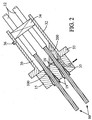
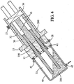
Figures 2-4 are schematic views of the anchoring device offigure 1 , in other phases of a method according to an embodiment of the invention; and -
Figure 5 is a schematic view of another embodiment of the anchoring device. - The structural cable shown in
figure 1 is made of a plurality oftendons 10 each consisting of ametallic strand 11 contained in an individualplastic sheath 12. Only twotendons 10 are shown in the figures for simplicity of the drawing. Typically, a higher number of tendons, e.g. a few tens of tendons, are used. Thetendons 10 extend parallel to each other along the prescribed path of the structural cable, e.g. along the inclined path of a stay cable between the deck and a pylon of a bridge, or along the path specified for a pre-stressing cable. - The structural cable is anchored at both ends. The anchoring devices transfer the tensile load of the cable to the structure.
- In order to firmly grip the
tendons 10 in the anchoring devices, theplastic sheaths 12 are removed at the ends of thetendons 10, thus exposing the metal of thestrands 11. At each end of the cable, the bare parts of thetendons 10 extend through and beyond ananchor block 15 of the anchoring device. Theanchor block 15 has a number ofchannels 16 extending between its rear side 17 (towards the running part of the cable where the tendons will be under tension) and itsfront side 18. Eachtendon 10 is received within one of thechannels 16 with a blockingmember 19. - In the illustrated embodiment, each
channel 16 designed to receive atendon 10 has a cylindrical part near therear side 17 of theanchor block 15, with a diameter slightly larger than that of thestrand 11, extended by a conical part which tapers outwardly towards thefront side 18 of theanchor block 15. The blocking member is in the form of aconical jaw 19 placed in the conical part of thechannel 16 to grip themetallic strand 11. Thejaw 19 has a cylindrical axial bore for receiving the strand, and is made of a plurality of sectors (e.g. three sectors) held together by aring 20 inserted in an annular groove located near the wide end of thejaw 19. - To install the cable, its
tendons 10 are inserted into theirrespective channels 16 with theconical jaws 19, the tensile force is applied by holding thestrands 11 in their parts projecting from thefront face 18 of theanchor block 15, pulling them using an actuator such as a hydraulic jack, and pushing thejaws 19 into thechannels 16. When the actuator is deactivated, thejaws 19 block thestrands 11 in theirchannels 16. This tensioning operation can be performed strand by strand, group of strands by group of strands, or collectively for the whole cable. - After the cable has been tensioned, there remain some intervals in the
channels 16, in particular around thestrands 11 in their cylindrical parts and between the jaw sectors in their conical parts. - A first injection phase is carried out to make sure that these intervals are filled with a
substance 100 which will protect the metal from corrosion. - In an embodiment, the substance with which the
channels 16 are filled in the first injection phase is a wax or grease. However, it may also be a curing material such as a polymer or a resin. - As shown in
figure 1 , the first injection phase can be performed for eachchannel 16 by using a bell-shapedcover 25 over the inlet of the channel. Thecover 25 is sealingly applied against thefront side 18 of theanchor block 15 using agasket 26, and its opposite end has an aperture providing a passage for thestrand 11. A sealingring 27 is placed around thestrand 11 to seal the front end of thecover 25 which is secured in its position by aring 28 clamped on the free end of thestrand 11. - The
protective material 100 is injected in a fluid or soft phase through aninlet 29 provided in thecover 25. Since the volume of the intervals not occupied by the metallic strand and jaw is known with precision, a regulated amount of protective material can be injected into eachchannel 16 to ensure complete filling of the channel. An injection pump (not shown) is controlled to inject the set amount ofprotective material 100 inside thecover 25 to completely fill thechannel 16. - The attachment of the bell-shaped
cover 25 to thestrand 11 ensures that thecover 25 is kept in place at the inlet of thechannel 16 while the protective material is injected under pressure to overcome the head loss within thechannel 16. It will be noted that other mechanisms can be used to hold the cover in that step, for example attached to theanchor block 15. - The filling
material 100 injected into thechannels 16 is allowed to cure (if it is a polymer or resin) or to solidify by cooling (if it is a wax) and thecover 25 is removed from the front side of theanchor block 15. If the filling 100 is a thick material such as grease, no hardening time is needed and the cover may be removed just after the injection. An amount ofprotective material 100 may or may not remain on the portion of thestrand 11 which was contained in thecover 25. - After the first injection phase, a second injection phase is carried out to fill the other closed volume(s) of the anchorage with protective material. In the embodiment illustrated by
figures 1-4 , there are two chambers to be filled, one 30 on the rear side of theanchor block 15 and one 31 on the front side. These twochambers protective material - The
first chamber 30 on therear side 17 of the anchor block is delimited radially by atube 32 through with the tensioned parts of thetendons 10 extend. The ends of theplastic sheaths 12 of the tendons are located within thechamber 30. Opposite theanchor block 15, thechamber 30 is closed by a sealingdevice 34, for example a stuffing box arrangement as described inWO 01 /20098 A1 chamber 30 from the outside while leaving passages for thetendons 10. - In this example, the front end of the
tube 32 has aflange 33 which forms a bearing surface for theanchor block 15, theflange 33 being applied against the structure equipped with the cable. It will be appreciated that the anchorage may have various other arrangements within the scope of the present invention. - The injection of the
protective material 200 into the first chamber 30 (figure 2 ) is performed though an inlet which, in the illustrated example, is formed by anopening 35 provided in theanchor block 15, in a low part of thechamber 30. In the illustrated structure, theopening 35 is bent to be accessible on a lateral side of theanchor block 15. It may also be straight and accessible on thefront side 18 of theanchor block 15. Avent 36 is formed in an upper part of thetube 32 to evacuate the air contained in thechamber 30 during the injection step. Once the injection is complete, thevent 36 is closed by a plug 37 (figure 3 ) and theprotective material 200 is allowed to harden or solidify, if needed, prior to closing the inlet opening 35 with anotherplug 38. - The
second chamber 31 on thefront side 18 of the anchor block is delimited by acase 40 shown infigure 4 . Thecase 40 is mounted on theanchor block 15 by means of bolts or other fixing means (not shown). A sealingring 41 is provided between the rear end of thecase 40 and thefront face 18 of the anchor block to prevent the protective material from leaking when injected. Thecase 40 is dimensioned to contain the bare ends of all thetendons 10 of the cable. Its lower part has anopening 42 for injecting theprotective material 300 and its upper part has avent 43 for evacuating the air when theprotective material 300 is injected. - The
protective material 300 injected into thesecond chamber 31 fills all the remaining voids. When it flows out though thevent 43, the injection is stopped and aplug 45 is placed on thevent 43. The injectedprotective material 300 is allowed to harden or solidify, if needed, prior to closing the inlet opening 42 with another plug. - The protective material injected to fill (i) the
channels 16, (ii) thechamber 30 at the rear of theanchor block 15 and (iii) thechamber 31 at the front of theanchor block 15 can be selected independently for each volume to be filled, thus permitting an optimization of the anchorage by choosing each material for its properties as desired. - The
chamber 31 located at the front of theanchor block 15 may be opened, by removing thecase 40, during the lifetime of the anchorage to enable checking of its proper operation. For this reason, it is typically desirable to use in that chamber 31 aprotective material 300 which can be easily removed. A wax is an advantageous material for this purpose since it can be melted or at least softened by heating and pumped out. Grease can also be used. - The gripping and anchoring of the
tendons 10 takes place in thechannels 16. Aflexible material 100 having lubricating properties, such as grease or wax, is suitable in view of its good fatigue behavior which enhances the ultimate strength of the tendons. - The
chamber 30 at the rear of theanchor block 15 is potentially exposed to infiltrations of water flowing along the structure or the cable. A flexible, sticky andcoherent material 200 is often a good choice to best prevent such infiltrations. A polymer or a resin is advantageously injected in that part of the anchorage. -
Figure 5 illustrates an alternative embodiment of an anchoring device, for which the second injection phase, i.e. after filling of thechannels 16 where the tendons are blocked, is essentially performed in one step. The chamber thus filled is made of twoparts more communication channels 52. Thefirst part 50 is located on therear side 17 of theanchor block 15 and is functionally similar to thefirst chamber 30 of the embodiment shown infigures 1-4 , being delimited by acylindrical tube 32 and a stuffing box-type of sealingdevice 34. Thesecond part 51 is located on thefront side 18 of theanchor block 15 and is functionally similar to thesecond chamber 31 of the embodiment shown infigures 1-4 , being delimited by acase 40. Thecommunication channels 52 do not contain tendons and extend through theanchor block 15 parallel to thechannels 16 containing the tendons. - After installation and tensioning of the
tendons 10, the first injection phase is performed to fill thechannels 16 with aprotective substance 100 as described with reference tofigure 1 . Then thecase 40 is assembled on theanchor block 15 and the second injection phase is performed to inject aprotective material 400 in the two-part chamber 50-51. - The example of
figure 5 is, for example, that of the anchorage of the lower end of an inclined stay cable. In this configuration the lower part of the anchorage is in the lower part of the case aninlet 42 is provided. As in the previous embodiment, twovents rear part 50 of the chamber and the other (43) in the upper part of thefront part 51 of the chamber. During the second injection phase, the level of thefluid material 400 rises. When it reaches thevent 43, it overflows and aplug 45 is put on thatvent 43 to continue the injection, thus permitting theprotective material 400 to rise further through thecommunication channels 52 and into therear part 50 of the chamber. When theother vent 36 is reached, the second injection phase is over and a plug is put on thevent 36. Theprotective material 400 is allowed to harden or solidify, if needed, prior to closing the inlet opening 42 with another plug. - In the embodiment of
figure 5 , theprotective material 400 injected into the chamber 50-51 in the second phase is preferably, though not necessarily, the same as theprotective material 100 injected into thechannels 16 in the first phase. For example, a wax or grease may be injected into thechannels 16 and then into the two-part chamber 50-51. However, specifications of a given work can make it preferable to use different filler materials. - In yet another embodiment, the chamber filled in the second injection phase is located only on the front side of the
anchor block 15. Theplastic sheaths 12 of thetendons 10 then have their end sections inside thechannels 16 of theanchor block 15 or in individual extensions of those channels behind theanchor block 15. - In this case, the first injection phase is performed to fill the
channels 16 and/or their extensions with theprotective material 100. The filling is made at least in the parts of thechannels 16 and/or their extensions where the metal of the strand is free of plastic sheath. The separate injection of the protective material into thechannels 16 and/or their extensions ensures a reliable filling irrespective of the variable head losses typically experienced by the injected substance in those channels. - Afterwards, the second injection phase is carried out to introduce the
protective material 300, which is preferably different from the previously injectedprotective material 100, into thechamber 31 located only on thefront side 18 of theanchor block 15 and containing the end portions of thestrands 11. This can be performed in the same manner as described with reference tofigure 4 . - In the case where the
chamber 31 to be filled with protective material is located only on the front side of theanchor block 15, wax or grease will often be a suitable choice for the protective material both in thechannels 16 and in thechamber 31 because of its good fatigue properties (for the channels 16) and because it is relatively easy to remove (for the chamber 31). However, other choices may be suitable or preferable. For instance, water-tightness at the rear of the channels in such an anchorage design can be a concern. For this reason, an adhering filler material such as a polymer or a resin may be used in thechannels 16, while a wax or grease is injected into thechamber 31. - The above-described method of protecting the bare ends of the tendons of a structural cable using two or more injection phases in different parts of the anchoring device is applicable to the installation of a new cable. It is also applicable to the maintenance or repair of an existing cable. In this case, the protective filler material which was previously located in the different parts of the anchoring device may be removed (for example using a method as described in French patent application No.
11 52557 filed on March 28, 2011 - While a detailed description of exemplary embodiments of the invention has been given above, various alternatives, modifications, and equivalents will be apparent to those skilled in the art.
- In particular, it will be appreciated that the above-mentioned choices for the protective materials with which the different parts of the anchorage are filled is a matter of design optimization, and may be changed depending on the functionalities desired for a specific anchorage design having a specific geometrical configuration or disposition.
- It will also be appreciated that the above-described installation method, using several injection phases to fill first the
channels 16 containing tendons and then one or more chambers on one or both sides of theanchor block 15, provides the benefit of ensuring proper filling and protection of the metallic tendons even in cases where the same protective substance is used in all parts of the anchorage.
Claims (15)
- A method of protecting an end of a cable made of a plurality of parallel tendons (10) and anchored using an anchor block (15) having a front side (18), a rear side (17) and channels (16, 52) extending between the front and rear sides, each tendon of the cable being held in a respective channel of the anchor block with a blocking member (19), characterised in that said method comprises:- performing a first phase of injecting protective material (100) into at least some of the channels (16) of the anchor block, each of said channels (16, 25) receiving one of said tendons (10);- forming a chamber (31; 50-51) on at least the front side of the anchor block, end portions of the plurality of tendons being contained in said chamber; and- performing a second phase of injecting protective material (300; 400) into said chamber, whereby the protective material injected in the second phase is in contact with the end portions of the tendons and is filling said chamber.
- The method as claimed in claim 1, wherein each channel (16) of the anchor block (15) containing a tendon (10) receives protective material (100) in the first injection phase.
- The method as claimed in claim 1 or 2, wherein the first injection phase comprises, for each channel (16):- sealingly applying a bell-shaped cover (25) on an inlet of the channel;- injecting protective material (100) inside the bell-shaped cover to force the protective material into the channel; and- removing the bell-shaped cover.
- The method as claimed in claim 3, wherein the bell-shaped cover (25) has a passage for a tendon (10) of the cable extending through the channel (16), and wherein the bell-shaped cover is attached to said tendon when the protective material (100) is injected inside the bell-shaped cover.
- The method as claimed in any one of the preceding claims, wherein the protective material (100) injected into the channels (16) of the anchor block (15) in the first phase is a wax or grease.
- The method as claimed in any one of the preceding claims, wherein the protective material (300; 400) injected into the chamber (31; 50-51) in the second phase is different from the protective material (100) injected into the channels (16) of the anchor block (15) in the first phase.
- The method as claimed in any one of the preceding claims, wherein the chamber has at least two parts (50-51) on the front and rear sides of the anchor block, respectively, connected together by at least one communication channel (52) extending through the anchor block (15), wherein protective material is not injected into the communication channel in the first injection phase and wherein the second injection phase has a common step of injecting protective material (400) into one of the parts of the chamber and, from said one of the parts of the chamber, into another part of the chamber through the at least one communication channel.
- The method as claimed in claim 7, wherein no tendon of the cable is put in the communication channel (52).
- The method as claimed in any one of claims 1 to 6, wherein a first chamber (30) containing tensioned portions of the tendons (10) is formed on the rear side (17) of the anchor block (15), wherein a second chamber (31) containing said end portions of the tendons is formed on a front side (18) of the anchor block, and wherein protective material (200, 300) is injected into the first chamber and separately into the second chamber.
- The method as claimed in claim 9, wherein the protective material (200) injected into the first chamber (30) is different from the protective material (300) injected into the second chamber (31).
- The method as claimed in claim 10, wherein the protective material (200) injected into the first chamber (30) is a polymer or a resin.
- The method as claimed in claim 10 or 11, wherein the protective material (300) injected into the second chamber (31) is a wax or grease.
- The method as claimed in any one of claims 1 to 6, wherein a chamber is formed only on the front side of the anchor block (15), said chamber containing end portions of the plurality of tendons (10) of the cable and receiving protective material (300) in the second injection phase.
- The method as claimed in claim 13, wherein the protective material (300) injected into said chamber in the second injection phase is a wax or grease.
- The method as claimed in claim 13 or 14, wherein the protective material (100) injected into the channels (16) of the anchor block (15) in the first phase is a polymer or a resin.
Priority Applications (1)
| Application Number | Priority Date | Filing Date | Title |
|---|---|---|---|
| HUE11730736A HUE029019T2 (en) | 2011-04-15 | 2011-04-15 | Method of protecting the end of a multi-tendon cable |
Applications Claiming Priority (1)
| Application Number | Priority Date | Filing Date | Title |
|---|---|---|---|
| PCT/IB2011/001046 WO2012140462A1 (en) | 2011-04-15 | 2011-04-15 | Method of protecting the end of a multi-tendon cable |
Publications (2)
| Publication Number | Publication Date |
|---|---|
| EP2697447A1 EP2697447A1 (en) | 2014-02-19 |
| EP2697447B1 true EP2697447B1 (en) | 2016-02-24 |
Family
ID=44628235
Family Applications (1)
| Application Number | Title | Priority Date | Filing Date |
|---|---|---|---|
| EP11730736.3A Active EP2697447B1 (en) | 2011-04-15 | 2011-04-15 | Method of protecting the end of a multi-tendon cable |
Country Status (11)
| Country | Link |
|---|---|
| US (1) | US9446541B2 (en) |
| EP (1) | EP2697447B1 (en) |
| KR (3) | KR20190097322A (en) |
| AU (1) | AU2011365314B2 (en) |
| DK (1) | DK2697447T3 (en) |
| ES (1) | ES2572636T3 (en) |
| HU (1) | HUE029019T2 (en) |
| MX (1) | MX339730B (en) |
| PL (1) | PL2697447T3 (en) |
| RU (1) | RU2566541C2 (en) |
| WO (1) | WO2012140462A1 (en) |
Families Citing this family (5)
| Publication number | Priority date | Publication date | Assignee | Title |
|---|---|---|---|---|
| DE102013215136A1 (en) * | 2013-08-01 | 2015-02-05 | Dywidag-Systems International Gmbh | Corrosion-protected tension member and plastically deformable disc made of anti-corrosion material for such a tension member |
| IT201800005437A1 (en) * | 2018-05-16 | 2019-11-16 | FIXING DEVICE FOR TIE ROPES | |
| CN109098086A (en) * | 2018-10-22 | 2018-12-28 | 湖南路桥建设集团有限责任公司 | A kind of anticorrosion structure and method of suspension cable anchor head steel strand wires |
| JP6807482B1 (en) * | 2020-08-18 | 2021-01-06 | 中日本ハイウェイ・エンジニアリング東京株式会社 | Tendon's head fixation structure |
| US12054947B1 (en) * | 2024-01-08 | 2024-08-06 | King Faisal University | Multi-layer wedge anchorage for FRP plates and FRP tendons |
Citations (9)
| Publication number | Priority date | Publication date | Assignee | Title |
|---|---|---|---|---|
| FR2492870A1 (en) | 1980-10-27 | 1982-04-30 | Precontrainte Structures Ste F | Anchor for cable in concrete - has perforated plate sandwiched between sealing cap and steel support plate |
| DE3339058A1 (en) | 1983-10-28 | 1985-05-15 | Dyckerhoff & Widmann AG, 8000 München | Exposed tightenable tension member comprising one or more tension elements, such as steel rods, wires or strands |
| DE3224702C2 (en) | 1982-07-02 | 1986-01-16 | Dyckerhoff & Widmann AG, 8000 München | Device for anchoring and coupling a bundle tendon for prestressed concrete |
| CH676617A5 (en) | 1987-03-13 | 1991-02-15 | Dyckerhoff & Widmann Ag | |
| DE3801451C2 (en) | 1987-10-15 | 1994-09-29 | Dyckerhoff & Widmann Ag | Corrosion-protected free tension member, primarily tendon for prestressed concrete without bond |
| DE3644551C2 (en) | 1986-12-24 | 1994-12-08 | Zueblin Ag | Anchoring for a composite tendon |
| EP0703326B1 (en) | 1994-09-22 | 1999-11-03 | DYCKERHOFF & WIDMANN AG | Corrosion protected tension member for use in prestressed concrete with post-tensioning |
| DE20311950U1 (en) | 2003-08-02 | 2004-12-09 | Dywidag-Systems International Gmbh | Corrosion-protected tension member, in particular tendon for prestressed concrete |
| DE60102061T4 (en) | 2000-12-04 | 2009-10-22 | Freyssinet | Individually protected strand, its use in construction engineering and process for its production |
Family Cites Families (17)
| Publication number | Priority date | Publication date | Assignee | Title |
|---|---|---|---|---|
| FR1152557A (en) | 1954-09-21 | 1958-02-20 | Device for automatic lifting of blades for shedding in table looms and at home | |
| BE794024A (en) * | 1972-01-21 | 1973-05-02 | Brandestini Antonio | ANCHORING DEVICE FOR CABLES COMPOSED OF STRANDS |
| JPS59173712U (en) * | 1983-05-09 | 1984-11-20 | 株式会社 春本鐵工所 | Bridge cable anchor socket |
| GB8407596D0 (en) | 1984-03-23 | 1984-05-02 | Manuf Aceros Caucho Sa | Reinforcing tendon |
| FR2623551B1 (en) | 1987-11-25 | 1992-04-24 | Freyssinet Int Stup | IMPROVEMENTS ON SURFACES AND THEIR COMPONENTS |
| DE4118897A1 (en) * | 1991-06-08 | 1992-12-10 | Hochtief Ag Hoch Tiefbauten | Building component anchor system e.g. for strands in concrete block, etc. - has shrouding tube around anchor cables with sepg. and lubricating coating, giving easy exchange of clamp |
| US5173982A (en) * | 1991-07-25 | 1992-12-29 | Greiner Inc, Southern | Corrosion protection system |
| DE29504739U1 (en) * | 1995-03-20 | 1995-05-18 | Dyckerhoff & Widmann AG, 81902 München | Corrosion-protected tension member, primarily external tendon for prestressed concrete without bond |
| DE19733822A1 (en) | 1997-08-05 | 1999-02-11 | Dyckerhoff & Widmann Ag | Method for installing and tensioning a freely tensioned tension member and device for carrying out the method |
| RU2131010C1 (en) * | 1997-12-30 | 1999-05-27 | Государственный научно-исследовательский, проектно-конструкторский и изыскательский институт "Атомэнергопроект" | Prestressed ferroconcrete constructions |
| FR2798410B1 (en) | 1999-09-15 | 2001-11-23 | Freyssinet Int Stup | ANCHORING DEVICE FOR ATTACHING A STRUCTURAL CABLE TO A CONSTRUCTION ELEMENT |
| DE60134304D1 (en) | 2001-01-29 | 2008-07-17 | Vsl Int Ag | Apparatus and method for anchoring a cable-stayed end to a base |
| FR2822177B1 (en) | 2001-03-15 | 2004-04-30 | Freyssinet Int Stup | ANCHORING DEVICE FOR PRE-STRESS ARMATURES, PRE-STRESS SYSTEM INCLUDING THE DEVICE, AND APPROPRIATE REINFORCEMENT |
| JP2003286759A (en) * | 2002-03-28 | 2003-10-10 | Ps Mitsubishi Construction Co Ltd | PC fixing device and method |
| JP2004052539A (en) * | 2002-05-30 | 2004-02-19 | Anderson Technology Kk | Tension end structure of prestressed concrete structure, and construction method for tension end |
| JP4387380B2 (en) * | 2006-06-15 | 2009-12-16 | 弘和産業株式会社 | Anchor repair method, anchor head and head back mechanism |
| AU2011365315B2 (en) * | 2011-04-15 | 2017-02-23 | Soletanche Freyssinet | Anchoring device for a multi-tendon cable |
-
2011
- 2011-04-15 AU AU2011365314A patent/AU2011365314B2/en active Active
- 2011-04-15 KR KR1020197023770A patent/KR20190097322A/en not_active Ceased
- 2011-04-15 US US14/009,767 patent/US9446541B2/en active Active
- 2011-04-15 RU RU2013150822/03A patent/RU2566541C2/en active
- 2011-04-15 EP EP11730736.3A patent/EP2697447B1/en active Active
- 2011-04-15 KR KR1020137029333A patent/KR20140022402A/en not_active Ceased
- 2011-04-15 MX MX2013011988A patent/MX339730B/en active IP Right Grant
- 2011-04-15 HU HUE11730736A patent/HUE029019T2/en unknown
- 2011-04-15 PL PL11730736.3T patent/PL2697447T3/en unknown
- 2011-04-15 DK DK11730736.3T patent/DK2697447T3/en active
- 2011-04-15 ES ES11730736.3T patent/ES2572636T3/en active Active
- 2011-04-15 WO PCT/IB2011/001046 patent/WO2012140462A1/en not_active Ceased
- 2011-04-15 KR KR1020187018507A patent/KR102012838B1/en active Active
Patent Citations (9)
| Publication number | Priority date | Publication date | Assignee | Title |
|---|---|---|---|---|
| FR2492870A1 (en) | 1980-10-27 | 1982-04-30 | Precontrainte Structures Ste F | Anchor for cable in concrete - has perforated plate sandwiched between sealing cap and steel support plate |
| DE3224702C2 (en) | 1982-07-02 | 1986-01-16 | Dyckerhoff & Widmann AG, 8000 München | Device for anchoring and coupling a bundle tendon for prestressed concrete |
| DE3339058A1 (en) | 1983-10-28 | 1985-05-15 | Dyckerhoff & Widmann AG, 8000 München | Exposed tightenable tension member comprising one or more tension elements, such as steel rods, wires or strands |
| DE3644551C2 (en) | 1986-12-24 | 1994-12-08 | Zueblin Ag | Anchoring for a composite tendon |
| CH676617A5 (en) | 1987-03-13 | 1991-02-15 | Dyckerhoff & Widmann Ag | |
| DE3801451C2 (en) | 1987-10-15 | 1994-09-29 | Dyckerhoff & Widmann Ag | Corrosion-protected free tension member, primarily tendon for prestressed concrete without bond |
| EP0703326B1 (en) | 1994-09-22 | 1999-11-03 | DYCKERHOFF & WIDMANN AG | Corrosion protected tension member for use in prestressed concrete with post-tensioning |
| DE60102061T4 (en) | 2000-12-04 | 2009-10-22 | Freyssinet | Individually protected strand, its use in construction engineering and process for its production |
| DE20311950U1 (en) | 2003-08-02 | 2004-12-09 | Dywidag-Systems International Gmbh | Corrosion-protected tension member, in particular tendon for prestressed concrete |
Non-Patent Citations (7)
| Title |
|---|
| "Rosario-Victoria-Brücke", STRUCTURAE, 2003, pages 1 - 3, XP055329438, Retrieved from the Internet <URL:https://structurae.de/bauwerke/rosario-victoria-bruecke> |
| "Strelasundquerung", WIKIPEDIA, pages 1 - 20, XP055329428 |
| "Ziegelgrabenbrücke", STRUCTURAE, 2007, pages 1 - 7, XP055329445 |
| CH. GLÄSER ET AL.: "?Die zweite Strelasundquerung - Erste deutsche An- wendung von Parallellitzenseilen", BAND, vol. 82, April 2007 (2007-04-01), pages 170 - 176, XP055329497 |
| D. JUNGWIRTH ET AL.: "Experience during the First Application of the New fib Stay Cable Recommendation 2005 on the Ziegelgraben Bridge to the Isle of Rügen/ Germany", ?PROCEEDINGS OF THE 2ND FIB CONGRESS, 5 June 2006 (2006-06-05), Neapel, Italien, pages 1 - 12, XP055329498 |
| EINTRAG ZUR ZIEGELGRABENBRÜCKE IN DER WEBSITE ''STRUC- TURAE, 2007, XP055329471, Retrieved from the Internet <URL:https://structurae.de/bauwerke/ziegelgraben-bruecke> |
| K. KLEINHANSS: "?Die 2. Strelasundquerung mit der Rügenbrücke - inter- aktive Entwicklung in der Bauphase", VDI-GESELLSCHAFT BAUTECHNIK, 2006, pages 224 - 240, XP055329452 |
Also Published As
| Publication number | Publication date |
|---|---|
| AU2011365314B2 (en) | 2017-04-27 |
| MX339730B (en) | 2016-06-06 |
| EP2697447A1 (en) | 2014-02-19 |
| RU2013150822A (en) | 2015-05-20 |
| KR20180077327A (en) | 2018-07-06 |
| RU2566541C2 (en) | 2015-10-27 |
| HUE029019T2 (en) | 2017-02-28 |
| KR20140022402A (en) | 2014-02-24 |
| WO2012140462A1 (en) | 2012-10-18 |
| US9446541B2 (en) | 2016-09-20 |
| KR20190097322A (en) | 2019-08-20 |
| DK2697447T3 (en) | 2016-05-30 |
| MX2013011988A (en) | 2013-11-20 |
| HK1189395A1 (en) | 2014-06-06 |
| AU2011365314A1 (en) | 2013-10-24 |
| KR102012838B1 (en) | 2019-08-21 |
| US20140021649A1 (en) | 2014-01-23 |
| ES2572636T3 (en) | 2016-06-01 |
| PL2697447T3 (en) | 2016-09-30 |
Similar Documents
| Publication | Publication Date | Title |
|---|---|---|
| EP2697446B1 (en) | Anchoring assembly | |
| US9446541B2 (en) | Method of protecting the end of a multi-tendon cable | |
| EP2550400B2 (en) | Sealing arrangement | |
| US20200199831A1 (en) | Improved assembly comprising a structural cable and a saddle | |
| KR101757406B1 (en) | Improvement for a strand guiding device | |
| KR102027925B1 (en) | Reinforcement method of bridge girder using coated strand tendon and anchoring device used therein | |
| CN105089049B (en) | Anchor cable outer anchor head steel strand protective device and installation method thereof | |
| HK1189395B (en) | Method of protecting the end of a multi-tendon cable | |
| HK1189254B (en) | Anchoring assembly | |
| KR20120110054A (en) | Method of draining a system for anchoring a structural cable to a construction element | |
| KR102292311B1 (en) | Cable anchorage construction method for watertight device using double tube | |
| JP2014147212A (en) | Cable tray water pressure processing method and water pressure structure | |
| KR102031412B1 (en) | Material testing apparatus and Method for testing material using the same | |
| JP2005207218A (en) | Cable protection and securing method | |
| JP2005207122A (en) | Cable protection and securing method | |
| HK1231148A (en) | Improvement for a strand guiding device | |
| HK1231148A1 (en) | Bridge support frame and method for protecting strand from corroding in the same | |
| HK40004740A (en) | Cable anchorage with seal element | |
| HK1177775A (en) | Improvement for a strand guiding device | |
| HK1170276B (en) | Method of draining a system for anchoring a structural cable to a construction element | |
| HK1178226B (en) | Sealing arrangement |
Legal Events
| Date | Code | Title | Description |
|---|---|---|---|
| PUAI | Public reference made under article 153(3) epc to a published international application that has entered the european phase |
Free format text: ORIGINAL CODE: 0009012 |
|
| 17P | Request for examination filed |
Effective date: 20131114 |
|
| AK | Designated contracting states |
Kind code of ref document: A1 Designated state(s): AL AT BE BG CH CY CZ DE DK EE ES FI FR GB GR HR HU IE IS IT LI LT LU LV MC MK MT NL NO PL PT RO RS SE SI SK SM TR |
|
| REG | Reference to a national code |
Ref country code: HK Ref legal event code: DE Ref document number: 1189395 Country of ref document: HK |
|
| DAX | Request for extension of the european patent (deleted) | ||
| RIN1 | Information on inventor provided before grant (corrected) |
Inventor name: MELLIER, ERIK Inventor name: SYLVESTRE, AURELIEN Inventor name: JOYE, STEPHANE Inventor name: STUBLER, JEROME |
|
| RAP1 | Party data changed (applicant data changed or rights of an application transferred) |
Owner name: SOLETANCHE FREYSSINET |
|
| GRAP | Despatch of communication of intention to grant a patent |
Free format text: ORIGINAL CODE: EPIDOSNIGR1 |
|
| INTG | Intention to grant announced |
Effective date: 20150730 |
|
| GRAS | Grant fee paid |
Free format text: ORIGINAL CODE: EPIDOSNIGR3 |
|
| GRAA | (expected) grant |
Free format text: ORIGINAL CODE: 0009210 |
|
| AK | Designated contracting states |
Kind code of ref document: B1 Designated state(s): AL AT BE BG CH CY CZ DE DK EE ES FI FR GB GR HR HU IE IS IT LI LT LU LV MC MK MT NL NO PL PT RO RS SE SI SK SM TR |
|
| REG | Reference to a national code |
Ref country code: GB Ref legal event code: FG4D |
|
| REG | Reference to a national code |
Ref country code: CH Ref legal event code: EP |
|
| REG | Reference to a national code |
Ref country code: AT Ref legal event code: REF Ref document number: 776827 Country of ref document: AT Kind code of ref document: T Effective date: 20160315 |
|
| REG | Reference to a national code |
Ref country code: IE Ref legal event code: FG4D |
|
| REG | Reference to a national code |
Ref country code: DE Ref legal event code: R096 Ref document number: 602011023409 Country of ref document: DE |
|
| REG | Reference to a national code |
Ref country code: FR Ref legal event code: PLFP Year of fee payment: 6 |
|
| REG | Reference to a national code |
Ref country code: RO Ref legal event code: EPE |
|
| REG | Reference to a national code |
Ref country code: PT Ref legal event code: SC4A Free format text: AVAILABILITY OF NATIONAL TRANSLATION Effective date: 20160520 |
|
| REG | Reference to a national code |
Ref country code: DK Ref legal event code: T3 Effective date: 20160529 |
|
| REG | Reference to a national code |
Ref country code: ES Ref legal event code: FG2A Ref document number: 2572636 Country of ref document: ES Kind code of ref document: T3 Effective date: 20160601 Ref country code: NL Ref legal event code: FP |
|
| REG | Reference to a national code |
Ref country code: LT Ref legal event code: MG4D |
|
| REG | Reference to a national code |
Ref country code: AT Ref legal event code: MK05 Ref document number: 776827 Country of ref document: AT Kind code of ref document: T Effective date: 20160224 |
|
| PG25 | Lapsed in a contracting state [announced via postgrant information from national office to epo] |
Ref country code: HR Free format text: LAPSE BECAUSE OF FAILURE TO SUBMIT A TRANSLATION OF THE DESCRIPTION OR TO PAY THE FEE WITHIN THE PRESCRIBED TIME-LIMIT Effective date: 20160224 Ref country code: FI Free format text: LAPSE BECAUSE OF FAILURE TO SUBMIT A TRANSLATION OF THE DESCRIPTION OR TO PAY THE FEE WITHIN THE PRESCRIBED TIME-LIMIT Effective date: 20160224 Ref country code: NO Free format text: LAPSE BECAUSE OF FAILURE TO SUBMIT A TRANSLATION OF THE DESCRIPTION OR TO PAY THE FEE WITHIN THE PRESCRIBED TIME-LIMIT Effective date: 20160524 |
|
| PG25 | Lapsed in a contracting state [announced via postgrant information from national office to epo] |
Ref country code: LT Free format text: LAPSE BECAUSE OF FAILURE TO SUBMIT A TRANSLATION OF THE DESCRIPTION OR TO PAY THE FEE WITHIN THE PRESCRIBED TIME-LIMIT Effective date: 20160224 Ref country code: LV Free format text: LAPSE BECAUSE OF FAILURE TO SUBMIT A TRANSLATION OF THE DESCRIPTION OR TO PAY THE FEE WITHIN THE PRESCRIBED TIME-LIMIT Effective date: 20160224 Ref country code: SE Free format text: LAPSE BECAUSE OF FAILURE TO SUBMIT A TRANSLATION OF THE DESCRIPTION OR TO PAY THE FEE WITHIN THE PRESCRIBED TIME-LIMIT Effective date: 20160224 Ref country code: RS Free format text: LAPSE BECAUSE OF FAILURE TO SUBMIT A TRANSLATION OF THE DESCRIPTION OR TO PAY THE FEE WITHIN THE PRESCRIBED TIME-LIMIT Effective date: 20160224 Ref country code: AT Free format text: LAPSE BECAUSE OF FAILURE TO SUBMIT A TRANSLATION OF THE DESCRIPTION OR TO PAY THE FEE WITHIN THE PRESCRIBED TIME-LIMIT Effective date: 20160224 |
|
| REG | Reference to a national code |
Ref country code: GR Ref legal event code: EP Ref document number: 20160400999 Country of ref document: GR Effective date: 20160628 |
|
| REG | Reference to a national code |
Ref country code: HK Ref legal event code: GR Ref document number: 1189395 Country of ref document: HK |
|
| PG25 | Lapsed in a contracting state [announced via postgrant information from national office to epo] |
Ref country code: EE Free format text: LAPSE BECAUSE OF FAILURE TO SUBMIT A TRANSLATION OF THE DESCRIPTION OR TO PAY THE FEE WITHIN THE PRESCRIBED TIME-LIMIT Effective date: 20160224 |
|
| REG | Reference to a national code |
Ref country code: DE Ref legal event code: R026 Ref document number: 602011023409 Country of ref document: DE |
|
| PLBI | Opposition filed |
Free format text: ORIGINAL CODE: 0009260 |
|
| PG25 | Lapsed in a contracting state [announced via postgrant information from national office to epo] |
Ref country code: CZ Free format text: LAPSE BECAUSE OF FAILURE TO SUBMIT A TRANSLATION OF THE DESCRIPTION OR TO PAY THE FEE WITHIN THE PRESCRIBED TIME-LIMIT Effective date: 20160224 Ref country code: SM Free format text: LAPSE BECAUSE OF FAILURE TO SUBMIT A TRANSLATION OF THE DESCRIPTION OR TO PAY THE FEE WITHIN THE PRESCRIBED TIME-LIMIT Effective date: 20160224 Ref country code: SK Free format text: LAPSE BECAUSE OF FAILURE TO SUBMIT A TRANSLATION OF THE DESCRIPTION OR TO PAY THE FEE WITHIN THE PRESCRIBED TIME-LIMIT Effective date: 20160224 |
|
| 26 | Opposition filed |
Opponent name: DYWIDAG-SYSTEMS INTERNATIONAL GMBH Effective date: 20161123 |
|
| PG25 | Lapsed in a contracting state [announced via postgrant information from national office to epo] |
Ref country code: LU Free format text: LAPSE BECAUSE OF FAILURE TO SUBMIT A TRANSLATION OF THE DESCRIPTION OR TO PAY THE FEE WITHIN THE PRESCRIBED TIME-LIMIT Effective date: 20160415 |
|
| PLAF | Information modified related to communication of a notice of opposition and request to file observations + time limit |
Free format text: ORIGINAL CODE: EPIDOSCOBS2 |
|
| PLAX | Notice of opposition and request to file observation + time limit sent |
Free format text: ORIGINAL CODE: EPIDOSNOBS2 |
|
| REG | Reference to a national code |
Ref country code: IE Ref legal event code: MM4A |
|
| PG25 | Lapsed in a contracting state [announced via postgrant information from national office to epo] |
Ref country code: BG Free format text: LAPSE BECAUSE OF FAILURE TO SUBMIT A TRANSLATION OF THE DESCRIPTION OR TO PAY THE FEE WITHIN THE PRESCRIBED TIME-LIMIT Effective date: 20160524 Ref country code: SI Free format text: LAPSE BECAUSE OF FAILURE TO SUBMIT A TRANSLATION OF THE DESCRIPTION OR TO PAY THE FEE WITHIN THE PRESCRIBED TIME-LIMIT Effective date: 20160224 |
|
| REG | Reference to a national code |
Ref country code: HU Ref legal event code: AG4A Ref document number: E029019 Country of ref document: HU |
|
| REG | Reference to a national code |
Ref country code: FR Ref legal event code: PLFP Year of fee payment: 7 |
|
| PLBB | Reply of patent proprietor to notice(s) of opposition received |
Free format text: ORIGINAL CODE: EPIDOSNOBS3 |
|
| PG25 | Lapsed in a contracting state [announced via postgrant information from national office to epo] |
Ref country code: IE Free format text: LAPSE BECAUSE OF NON-PAYMENT OF DUE FEES Effective date: 20160415 |
|
| PLBP | Opposition withdrawn |
Free format text: ORIGINAL CODE: 0009264 |
|
| PLBD | Termination of opposition procedure: decision despatched |
Free format text: ORIGINAL CODE: EPIDOSNOPC1 |
|
| REG | Reference to a national code |
Ref country code: DE Ref legal event code: R100 Ref document number: 602011023409 Country of ref document: DE |
|
| PLBM | Termination of opposition procedure: date of legal effect published |
Free format text: ORIGINAL CODE: 0009276 |
|
| STAA | Information on the status of an ep patent application or granted ep patent |
Free format text: STATUS: OPPOSITION PROCEDURE CLOSED |
|
| REG | Reference to a national code |
Ref country code: FR Ref legal event code: PLFP Year of fee payment: 8 |
|
| 27C | Opposition proceedings terminated |
Effective date: 20171113 |
|
| REG | Reference to a national code |
Ref country code: BE Ref legal event code: FP Effective date: 20160520 |
|
| PG25 | Lapsed in a contracting state [announced via postgrant information from national office to epo] |
Ref country code: CY Free format text: LAPSE BECAUSE OF FAILURE TO SUBMIT A TRANSLATION OF THE DESCRIPTION OR TO PAY THE FEE WITHIN THE PRESCRIBED TIME-LIMIT Effective date: 20160224 |
|
| PG25 | Lapsed in a contracting state [announced via postgrant information from national office to epo] |
Ref country code: MK Free format text: LAPSE BECAUSE OF FAILURE TO SUBMIT A TRANSLATION OF THE DESCRIPTION OR TO PAY THE FEE WITHIN THE PRESCRIBED TIME-LIMIT Effective date: 20160224 Ref country code: MT Free format text: LAPSE BECAUSE OF NON-PAYMENT OF DUE FEES Effective date: 20160430 Ref country code: IS Free format text: LAPSE BECAUSE OF FAILURE TO SUBMIT A TRANSLATION OF THE DESCRIPTION OR TO PAY THE FEE WITHIN THE PRESCRIBED TIME-LIMIT Effective date: 20160224 Ref country code: MC Free format text: LAPSE BECAUSE OF FAILURE TO SUBMIT A TRANSLATION OF THE DESCRIPTION OR TO PAY THE FEE WITHIN THE PRESCRIBED TIME-LIMIT Effective date: 20160224 |
|
| PG25 | Lapsed in a contracting state [announced via postgrant information from national office to epo] |
Ref country code: AL Free format text: LAPSE BECAUSE OF FAILURE TO SUBMIT A TRANSLATION OF THE DESCRIPTION OR TO PAY THE FEE WITHIN THE PRESCRIBED TIME-LIMIT Effective date: 20160224 |
|
| P01 | Opt-out of the competence of the unified patent court (upc) registered |
Effective date: 20230526 |
|
| PGFP | Annual fee paid to national office [announced via postgrant information from national office to epo] |
Ref country code: GB Payment date: 20260319 Year of fee payment: 16 |
|
| PGFP | Annual fee paid to national office [announced via postgrant information from national office to epo] |
Ref country code: DK Payment date: 20260319 Year of fee payment: 16 |
|
| PGFP | Annual fee paid to national office [announced via postgrant information from national office to epo] |
Ref country code: BE Payment date: 20260319 Year of fee payment: 16 Ref country code: IT Payment date: 20260319 Year of fee payment: 16 |
|
| PGFP | Annual fee paid to national office [announced via postgrant information from national office to epo] |
Ref country code: NL Payment date: 20260319 Year of fee payment: 16 |
|
| PGFP | Annual fee paid to national office [announced via postgrant information from national office to epo] |
Ref country code: FR Payment date: 20260319 Year of fee payment: 16 |
|
| PGFP | Annual fee paid to national office [announced via postgrant information from national office to epo] |
Ref country code: TR Payment date: 20260325 Year of fee payment: 16 |
|
| PGFP | Annual fee paid to national office [announced via postgrant information from national office to epo] |
Ref country code: PT Payment date: 20260323 Year of fee payment: 16 |
|
| PGFP | Annual fee paid to national office [announced via postgrant information from national office to epo] |
Ref country code: GR Payment date: 20260320 Year of fee payment: 16 Ref country code: PL Payment date: 20260325 Year of fee payment: 16 |
|
| REG | Reference to a national code |
Ref country code: CH Ref legal event code: U11 Free format text: ST27 STATUS EVENT CODE: U-0-0-U10-U11 (AS PROVIDED BY THE NATIONAL OFFICE) Effective date: 20260501 |
|
| PGFP | Annual fee paid to national office [announced via postgrant information from national office to epo] |
Ref country code: HU Payment date: 20260427 Year of fee payment: 16 |
|
| PGFP | Annual fee paid to national office [announced via postgrant information from national office to epo] |
Ref country code: ES Payment date: 20260504 Year of fee payment: 16 |
|
| PGFP | Annual fee paid to national office [announced via postgrant information from national office to epo] |
Ref country code: DE Payment date: 20260319 Year of fee payment: 16 |
|
| PGFP | Annual fee paid to national office [announced via postgrant information from national office to epo] |
Ref country code: RO Payment date: 20260414 Year of fee payment: 16 Ref country code: CH Payment date: 20260501 Year of fee payment: 16 |