EP2697341B1 - Verfahren zur durchführung einer hydrothermalen karbonisierungsreaktion und reaktionstank hierfür - Google Patents
Verfahren zur durchführung einer hydrothermalen karbonisierungsreaktion und reaktionstank hierfür Download PDFInfo
- Publication number
- EP2697341B1 EP2697341B1 EP12714679.3A EP12714679A EP2697341B1 EP 2697341 B1 EP2697341 B1 EP 2697341B1 EP 12714679 A EP12714679 A EP 12714679A EP 2697341 B1 EP2697341 B1 EP 2697341B1
- Authority
- EP
- European Patent Office
- Prior art keywords
- reaction
- biomass
- steam
- reaction chamber
- injection nozzles
- Prior art date
- Legal status (The legal status is an assumption and is not a legal conclusion. Google has not performed a legal analysis and makes no representation as to the accuracy of the status listed.)
- Active
Links
Images



Classifications
-
- B—PERFORMING OPERATIONS; TRANSPORTING
- B01—PHYSICAL OR CHEMICAL PROCESSES OR APPARATUS IN GENERAL
- B01J—CHEMICAL OR PHYSICAL PROCESSES, e.g. CATALYSIS OR COLLOID CHEMISTRY; THEIR RELEVANT APPARATUS
- B01J19/00—Chemical, physical or physico-chemical processes in general; Their relevant apparatus
- B01J19/24—Stationary reactors without moving elements inside
- B01J19/2405—Stationary reactors without moving elements inside provoking a turbulent flow of the reactants, such as in cyclones, or having a high Reynolds-number
-
- C—CHEMISTRY; METALLURGY
- C10—PETROLEUM, GAS OR COKE INDUSTRIES; TECHNICAL GASES CONTAINING CARBON MONOXIDE; FUELS; LUBRICANTS; PEAT
- C10L—FUELS NOT OTHERWISE PROVIDED FOR; NATURAL GAS; SYNTHETIC NATURAL GAS OBTAINED BY PROCESSES NOT COVERED BY SUBCLASSES C10G OR C10K; LIQUIFIED PETROLEUM GAS; USE OF ADDITIVES TO FUELS OR FIRES; FIRE-LIGHTERS
- C10L5/00—Solid fuels
- C10L5/40—Solid fuels essentially based on materials of non-mineral origin
- C10L5/44—Solid fuels essentially based on materials of non-mineral origin on vegetable substances
-
- C—CHEMISTRY; METALLURGY
- C01—INORGANIC CHEMISTRY
- C01B—NON-METALLIC ELEMENTS; COMPOUNDS THEREOF; METALLOIDS OR COMPOUNDS THEREOF NOT COVERED BY SUBCLASS C01C
- C01B32/00—Carbon; Compounds thereof
- C01B32/05—Preparation or purification of carbon not covered by groups C01B32/15, C01B32/20, C01B32/25, C01B32/30
-
- C—CHEMISTRY; METALLURGY
- C10—PETROLEUM, GAS OR COKE INDUSTRIES; TECHNICAL GASES CONTAINING CARBON MONOXIDE; FUELS; LUBRICANTS; PEAT
- C10L—FUELS NOT OTHERWISE PROVIDED FOR; NATURAL GAS; SYNTHETIC NATURAL GAS OBTAINED BY PROCESSES NOT COVERED BY SUBCLASSES C10G OR C10K; LIQUIFIED PETROLEUM GAS; USE OF ADDITIVES TO FUELS OR FIRES; FIRE-LIGHTERS
- C10L9/00—Treating solid fuels to improve their combustion
- C10L9/08—Treating solid fuels to improve their combustion by heat treatments, e.g. calcining
- C10L9/086—Hydrothermal carbonization
-
- B—PERFORMING OPERATIONS; TRANSPORTING
- B01—PHYSICAL OR CHEMICAL PROCESSES OR APPARATUS IN GENERAL
- B01J—CHEMICAL OR PHYSICAL PROCESSES, e.g. CATALYSIS OR COLLOID CHEMISTRY; THEIR RELEVANT APPARATUS
- B01J2219/00—Chemical, physical or physico-chemical processes in general; Their relevant apparatus
- B01J2219/24—Stationary reactors without moving elements inside
-
- B—PERFORMING OPERATIONS; TRANSPORTING
- B01—PHYSICAL OR CHEMICAL PROCESSES OR APPARATUS IN GENERAL
- B01J—CHEMICAL OR PHYSICAL PROCESSES, e.g. CATALYSIS OR COLLOID CHEMISTRY; THEIR RELEVANT APPARATUS
- B01J2219/00—Chemical, physical or physico-chemical processes in general; Their relevant apparatus
- B01J2219/24—Stationary reactors without moving elements inside
- B01J2219/2401—Reactors comprising multiple separate flow channels
- B01J2219/2402—Monolithic-type reactors
- B01J2219/2418—Feeding means
- B01J2219/2419—Feeding means for the reactants
-
- Y—GENERAL TAGGING OF NEW TECHNOLOGICAL DEVELOPMENTS; GENERAL TAGGING OF CROSS-SECTIONAL TECHNOLOGIES SPANNING OVER SEVERAL SECTIONS OF THE IPC; TECHNICAL SUBJECTS COVERED BY FORMER USPC CROSS-REFERENCE ART COLLECTIONS [XRACs] AND DIGESTS
- Y02—TECHNOLOGIES OR APPLICATIONS FOR MITIGATION OR ADAPTATION AGAINST CLIMATE CHANGE
- Y02E—REDUCTION OF GREENHOUSE GAS [GHG] EMISSIONS, RELATED TO ENERGY GENERATION, TRANSMISSION OR DISTRIBUTION
- Y02E50/00—Technologies for the production of fuel of non-fossil origin
- Y02E50/10—Biofuels, e.g. bio-diesel
-
- Y—GENERAL TAGGING OF NEW TECHNOLOGICAL DEVELOPMENTS; GENERAL TAGGING OF CROSS-SECTIONAL TECHNOLOGIES SPANNING OVER SEVERAL SECTIONS OF THE IPC; TECHNICAL SUBJECTS COVERED BY FORMER USPC CROSS-REFERENCE ART COLLECTIONS [XRACs] AND DIGESTS
- Y02—TECHNOLOGIES OR APPLICATIONS FOR MITIGATION OR ADAPTATION AGAINST CLIMATE CHANGE
- Y02E—REDUCTION OF GREENHOUSE GAS [GHG] EMISSIONS, RELATED TO ENERGY GENERATION, TRANSMISSION OR DISTRIBUTION
- Y02E50/00—Technologies for the production of fuel of non-fossil origin
- Y02E50/30—Fuel from waste, e.g. synthetic alcohol or diesel
Definitions
- the present invention relates to a method for carrying out a hydrothermal carbonization reaction in which biomass is supplied to a reaction space and the pressure and temperature reaction conditions required for the course of a hydrothermal carbonation reaction are created by blowing in steam, and a reaction tank for carrying out this process.
- a method and an apparatus for carrying it out is already known from the German Offenlegungsschrift DE 10 2007 022 840 A1 previously known.
- This method provides that in a reaction chain, first a pretreatment step is carried out, after which the pretreated biomass, which is preheated in this case, is placed in a reaction space. During transport of the biomass from the preheating in the reaction space using a feed pump in this case an increase in pressure is performed.
- WO 2010/092040 A1 discloses another method of hydrothermal carbonization.
- the essential process parameters required for the hydrothermal carbonation reaction to proceed are a sufficient pressure of the order of about 25 bar and a temperature of above 180 ° C, preferably between 210 and 230 ° C.
- the fed into the reaction chamber biomass has a certain heat capacity and therefore initially the outer, only significantly delayed then the inner regions of the supplied biomass reach the required reaction parameters, so that the Karbonmaschinesresure initially outside and significantly delayed only takes place inside.
- the present invention has the object to further improve the method for carrying out a hydrothermal Karbonmaschinesrecision.
- the basic idea underlying the invention is to distribute the biomass in the reaction space as evenly as possible and as finely as possible, so that the hydrothermal Carbonation reaction on the one hand as possible runs simultaneously in the entire biomass and thus the total duration of treatment of a batch is reduced as much as possible, and on the other hand, the carbonation reaction proceeds as completely as possible in the entire biomass in order to increase the yield as much as possible.
- a reaction tank having various types of injection nozzles for blowing in the steam can be used for this purpose.
- a first type of injection nozzles are placed tangentially to a vertical longitudinal axis of the reaction space, so that they have a circular turbulence cause the biomass within the reaction space.
- These tangential injection nozzles can be arranged, for example, in one plane and point in four different wind directions. In this case, the blowing direction is skewed with respect to the said longitudinal axis of the reaction space, so that the steam introduced from the injection nozzles practically orbits the longitudinal axis.
- vertical injection nozzles are also provided, the injection direction of which runs parallel to the said longitudinal axis of the reaction space, thereby causing the biomass to swirl against gravity.
- either the tangential or the vertical injection nozzles can be used, and a combination or a time alternation or subsequent switching on and off of individual nozzles is possible depending on the desired course of the reaction.
- the lighter carbonated particles will be more likely to be in the fluidizing center. Accordingly, it is intended to arrange the vertical injection nozzles so that they mainly blow the central part of the turbulence and thus spend the already carbonized, lighter particles further into the reaction space.
- the reaction space is an elongated Cylinder is, which has the injection nozzles in the bottom region.
- a lower section of the reaction space in the area of the injection nozzles can be tapered in a funnel shape in order to ensure the targeted recycling of the biomass which re-branches down outside the vortex to the injection nozzles.
- the steam at a particularly high speed preferably supersonic speed, ie about 350 m / s, is blown into the reaction space. Due to this enormous kinetic energy on the one hand, a particularly uniform distribution of the biomass in the reaction chamber and on the other hand, a further breaking up of the structures of the biomass, resulting in a finer grain size and thus to a faster flow of the reaction.
- An acceleration of the reaction can also be achieved by preheating the biomass prior to introduction into the reaction space, the preheating of the biomass ideally being carried out in the order of 140 ° C.
- the entire process according to the invention as described above can be influenced, for example, via a process control, by either preloading a programming adapted to the biomass used or performing it during the process.
- the essential setting parameters for this are the preheating temperature of the biomass, the injection rate of the steam and the temporal and spatial distribution of the steam to the various injection nozzles, which have a significant influence on the distribution of the biomass in the reaction space.
- This makes it possible to set different temperature and energy zones within the reaction space, so that not only the coal usually to be obtained in the process is produced, but also an operation, for example as a "bio-reactor” is possible in which in addition to the coal still others Products such as furfurals, especially hydroxymethylfurfural (HMF) arise.
- HMF hydroxymethylfurfural
- the reaction space can be subdivided into several parts, namely in particular a swirling area and a reaction area, where first the swirling takes place in the swirling area and then, after inserting the vertical injection nozzles, the biomass is brought into the reaction area where the main part of the carbonation reaction takes place. Due to this system described above, it is possible to obtain two or more different energetic potentials in a reaction space and at the same time to ensure the greatest possible uniform mixing.
- FIG. 1 shows a plant for carrying out a hydrothermal carbonization, which comprises a reaction tank 1, in which the actual carbonation reaction takes place.
- This reaction tank 1 is fed via a biomass feed 3 from a preheating tank 2 preheated biomass at a temperature of about 140 ° C. This is done via a biomass pump 4.
- hot steam of a steam supply 5 of the reaction tank 1 is provided by means of a steam pump, so that the biomass and the steam can be introduced simultaneously into the reaction tank 1.
- the reaction conditions for the course of the hydrothermal carbonization are created, which consist essentially of a suitable pressure in the amount of about 25 bar and a suitable temperature in the amount of about 210 to 230 ° C.
- the reaction tank 1 which is substantially cylindrical in shape and has a funnel-shaped formation in the bottom region, which opens in the steam supply 5 , 5 vertical injection nozzles 9 and tangential injection nozzles 10 in the region of this steam supply.
- FIG. 2 is first shown how a turbulence of the biomass is effected by the blown on the tangential injection nozzles 10 steam. Essentially, due to these tangential injection nozzles 10, rotational turbulence will take place around the longitudinal axis of the reaction tank 1, this part of the turbulence being used at the beginning of the reaction. Only after the onset of the actual carbonization is then in the FIG. 3 While the rotary swirl initially took place in a lower swirling area 7 of the reaction tank 1, a larger distribution of the reacting biomass in the reaction tank becomes due to this additional, vertical component of the swirling 1 causes, so that in this way different energy potentials can be realized in the container.
- FIG. 5 shows a plan view of the steam supply 5, which is constructed substantially bowl-shaped and in the present example a total of four tangential injection nozzles 10 and four vertical injection nozzles 9 has.
- the tangential injection nozzles 10 configured as venturi nozzles are aligned so that their blowing direction runs skewed to a longitudinal axis of the reaction tank 1 in four different directions.
- all four tangential injection nozzles 10 radiate in a common plane, but it is also readily possible to give the tangential injection nozzles a vertical component in order to achieve at least slightly upwardly directed turbulence at this stage.
- FIG. 6 more clearly shows the vertical injection nozzles 9, which are aligned substantially parallel to a vertical longitudinal axis of the reaction tank 1.
- the vertical injection nozzles 9 are substantially aligned with the center of a turbulence which arises around the longitudinal axis of the reaction tank 1 due to the action of the tangential injection nozzles 10.
- the vertical injection nozzles 9 are preferably switched on only when the carbonization reaction has already begun by the tangential injection nozzles 10.
Landscapes
- Chemical & Material Sciences (AREA)
- Organic Chemistry (AREA)
- Oil, Petroleum & Natural Gas (AREA)
- Physics & Mathematics (AREA)
- Thermal Sciences (AREA)
- Engineering & Computer Science (AREA)
- Combustion & Propulsion (AREA)
- Inorganic Chemistry (AREA)
- Chemical Kinetics & Catalysis (AREA)
- Processing Of Solid Wastes (AREA)
- Production Of Liquid Hydrocarbon Mixture For Refining Petroleum (AREA)
Description
- Die vorliegende Erfindung betrifft ein Verfahren zur Durchführung einer hydrothermalen Karbonisierungsreaktion, bei welchem einem Reaktionsraum Biomasse zugeführt und durch Einblasen von Dampf die für den Ablauf einer hydrothermalen Karbonisierungsreaktion erforderlichen Reaktionsbedingungen hinsichtlich Druck und Temperatur geschaffen werden, sowie einen Reaktionstank zur Durchführung dieses Verfahrens.
Ein derartiges Verfahren und eine Vorrichtung zur Durchführung desselben ist bereits aus der deutschen OffenlegungsschriftDE 10 2007 022 840 A1 vorbekannt. Dieses Verfahren sieht vor, dass in einer Reaktionskette zunächst ein Vorbehandlungsschritt durchgeführt wird, wonach die vorbehandelte Biomasse, welche hierbei vorgeheizt wird, in einen Reaktionsraum verbracht wird. Während des Transports der Biomasse aus dem Vorheizbehälter in den Reaktionsraum mithilfe einer Förderpumpe wird hierbei eine Druckerhöhung durchgeführt. Die in dem Reaktionsraum angekommene Biomasse wird sodann einer weiteren Druckerhöhung unterzogen, sowie mit Dampf, insbesondere Wasserdampf, beaufschlagt, um die Reaktionsbedingungen für eine hydrothermale Karbonisierung zu schaffen.WO 2010/092040 A1 offenbart ein weiteres Verfahren zur hydrothermalen Karbonisierung. Die wesentlichen Prozessparameter, welche zum Ablaufen der hydrothermalen Karbonisierungsreaktion erforderlich sind, sind ein ausreichender Druck in der Größenordnung von ca. 25 bar und eine Temperatur von oberhalb 180°C, vorzugsweise zwischen 210 und 230°C. Es besteht hierbei jedoch das Problem, dass die in den Reaktionsraum eingeförderte Biomasse eine gewisse Wärmekapazität aufweist und daher zunächst die äußeren, erst deutlich verzögert dann die inneren Bereiche der zugeführten Biomasse die erforderlichen Reaktionsparameter erreichen, so dass die Karbonisierungsreaktion zunächst außen und deutlich verzögert erst innen stattfindet. - Um dies zu umgehen, ist es bekannt, quirlartige Mischvorrichtungen innerhalb des Reaktionsraums vorzusehen, um eine gleichmäßige Verteilung der Temperatur bzw. des Drucks in der Biomasse zu erreichen. Dieses Vorgehen beschleunigt allerdings die Karbonisierungsreaktion bzw. das vollständige Durchreagieren der Biomasse nur in einem sehr geringen Umfang.
- Um den Durchsatz eines Reaktors zu erhöhen und damit die zur Aufrechterhaltung des Drucks und der Temperatur erforderliche Energie besser ausnutzen zu können, stellt sich die vorliegende Erfindung die Aufgabe, das Verfahren zur Durchführung einer hydrothermalen Karbonisierungsreaktion weiter zu verbessern.
- Dies gelingt durch ein Verfahren zur Durchführung einer hydrothermalen Karbonisierungsreaktion gemäß den Merkmalen des Hauptanspruchs sowie durch einen Reaktionstank einer Anlage zur hydrothermalen Karbonisierung von Biomasse gemäß den Merkmalen des nebengeordneten Anspruchs 10. Weitere, sinnvolle Ausgestaltungen des Verfahrens und des Reaktionstanks können den jeweiligen Unteransprüchen entnommen werden.
- Die grundsätzliche der Erfindung zu Grunde liegende Idee besteht darin, die Biomasse in dem Reaktionsraum möglichst gleichmäßig und möglichst fein zu verteilen, so dass die hydrothermale Karbonisierungsreaktion zum einen möglichst zeitgleich in der gesamten Biomasse abläuft und damit die Gesamtdauer der Behandlung eines Batches möglichst weit gesenkt wird, und andererseits die Karbonisierungsreaktion möglichst vollständig in der gesamten Biomasse abläuft, um den Ertrag möglichst weitgehend zu erhöhen.
- Hierzu wird damit gearbeitet, dass zeitgleich der benötigte Dampf mit der Biomasse in den Reaktionsraum eingebracht wird. Die Biomasse wird hierbei mit dem Dampfstrahl in Kontakt gebracht, so dass aufgrund der kinetischen Energie des Dampfstrahls eine Verwirbelung der Biomasse in dem Reaktionsraum eintritt, welche aufgrund der ebenfalls vorhandenen Wärmeenergie des Dampfstrahls auch zu einer Erhitzung der Biomasse auf die erforderliche Temperatur führt. Gleichzeitig oder auch unabhängig hiervon kann eine Druckerhöhung in dem Reaktionsraum stattfinden, um so die erforderlichen Umgebungsparameter für das Ablaufen der hydrothermalen Karbonisierungsreaktion zu schaffen. Indem der Dampfstrahl auf die Biomasse direkt gerichtet und diese in dem Reaktionsraum verwirbelt wird erfolgt zum einen eine gleichmäßige Verteilung der Biomasse in dem Reaktionsraum, und zum anderen eine weitere Zerkleinerung der Biomasse, so dass die Oberfläche der zu karbonisierenden Biomasse deutlich vergrößert wird. Damit wächst auch die Angriffsfläche für Druck und Temperatur, so dass die Karbonisierungsreaktion weitgehend zeitgleich in der gesamten Biomasse ablaufen kann.
- Im Einzelnen kann hierzu ein Reaktionstank verwendet werden, welcher verschiedene Arten von Einblasdüsen zum Einblasen des Dampfes aufweist. Eine erste Sorte von Einblasdüsen sind tangential zu einer lotrecht stehenden Längsachse des Reaktionsraums aufgestellt, so dass diese eine kreisförmige Verwirbelung der Biomasse innerhalb des Reaktionsraums bewirken. Diese tangentialen Einblasdüsen können beispielsweise in einer Ebene angeordnet sein und in vier verschiedene Windrichtungen zeigen. Hierbei ist die Einblasrichtung windschief gegenüber der genannten Längsachse des Reaktionsraums, so dass der aus den Einblasdüsen eingebrachte Dampf die Längsachse praktisch umkreist.
- Ergänzend sind auch vertikale Einblasdüsen vorgesehen sein, deren Einblasrichtung parallel zu der genannten Längsachse des Reaktionsraums verläuft, wodurch ein Aufwirbeln der Biomasse gegen die Schwerkraft bewirkt wird. Je nach gewünschtem Reaktionsverlauf können entweder die tangentialen oder die vertikalen Einblasdüsen verwendet werden, auch eine Kombination oder ein zeitliches Abwechseln bzw. späteres Zu- und Abschalten einzelner Düsen ist je nach gewünschtem Ablauf der Reaktion möglich.
Insbesondere wird als besonders vorteilhaft angesehen, wenn zunächst mithilfe der tangentialen Einblasdüsen eine Verwirbelung der Biomasse in dem Reaktionsraum erfolgt, und nach Einsetzen der Karbonisierungsreaktion dann die vertikalen Einblasdüsen zugeschaltet werden. Dies hat den Hintergrund, dass nach dem Einsetzen der Karbonisierungsreaktion die leichteren, karbonisierten Teilchen sich eher in der Verwirbelungsmitte aufhalten werden. Dementsprechend ist es vorgesehen, die vertikalen Einblasdüsen so anzuordnen, dass sie hauptsächlich den Mittelteil der Verwirbelung anblasen und somit die bereits karbonisierten, leichteren Teilchen weiter in den Reaktionsraum hinein verbringen. Insbesondere bietet es sich hierzu an, dass der Reaktionsraum ein langgestreckter Zylinder ist, welcher im Bodenbereich die Einblasdüsen aufweist. Ergänzend kann ein unterer Abschnitt des Reaktionsraums im Bereich der Einblasdüsen trichterförmig zulaufend sein, um die gezielte Rückführung der außerhalb der Wirbel wieder herabregnenden Biomasse zu den Einblasdüsen zu gewährleisten.
Um eine genügende kinetische Energie auf die Biomasse wirken zu lassen, ist es zudem vorgesehen, dass der Dampf mit einer besonders hohen Geschwindigkeit, vorzugsweise Überschallgeschwindigkeit, also ca. 350 m/s, in den Reaktionsraum eingeblasen wird. Durch diese enorme kinetische Energie erfolgt zum einen eine besonders gleichmäßige Verteilung der Biomasse in dem Reaktionsraum und andererseits auch ein weiteres Aufbrechen der Strukturen der Biomasse, was zu einer feineren Korngröße und damit zu einem schnelleren Ablauf der Reaktion führt.
Eine Beschleunigung der Reaktion kann zudem dadurch erreicht werden, dass ein Vorheizen der Biomasse vor dem Einbringen in den Reaktionsraum durchgeführt wird, wobei die Vorheizung der Biomasse idealerweise in der Größenordnung von 140°C vorgenommen wird.
Der gesamte erfindungsgemäße Prozess wie vorstehend beschrieben kann beispielsweise über eine Prozesssteuerung beeinflusst werden, indem entweder vorab eine auf die verwendete Biomasse angepasste Programmierung geladen oder während des Prozesses durchgeführt wird. Die wesentlichen Einstellparameter hierfür sind die Vorheiztemperatur der Biomasse, die Einblasgeschwindigkeit des Dampfes sowie die zeitliche und räumliche Verteilung des Dampfes auf die verschiedenen Einblasdüsen, welche wesentlichen Einfluss auf die Verteilung der Biomasse in dem Reaktionsraum haben. Hierdurch ist es möglich, innerhalb des Reaktionsraums verschiedene Temperatur- und Energiezonen einzustellen, so dass nicht lediglich die üblicherweise bei dem Prozess zu gewinnende Kohle entsteht, sondern auch ein Betrieb beispielsweise als "Bio-Reaktor" möglich ist, in welchem neben der Kohle noch andere Produkte wie beispielsweise Furfurale, insbesondere Hydroxymethylfurfural (HMF) entstehen. - Hierzu kann der Reaktionsraum in mehrere Teile unterteilt sein, nämlich insbesondere einen Verwirbelungsbereich und einen Reaktionsbereich, wobei zunächst die Verwirbelung in dem Verwirbelungsbereich stattfindet und dann nach Einsetzen der vertikalen Einblasdüsen die Biomasse in den Reaktionsbereich verbracht wird, wo der hauptsächliche Teil der Karbonisierungsreaktion abläuft. Aufgrund dieses vorbeschriebenen Systems besteht die Möglichkeit, zwei oder mehrere verschiedene energetische Potenziale in einem Reaktionsraum zu erhalten und gleichzeitig eine möglichst weitgehende, gleichmäßige Durchmischung zu gewährleisten.
- Die vorstehend beschriebene Erfindung wird im Folgenden anhand eines Ausführungsbeispiels näher erläutert.
- Es zeigen
- Figur 1
- eine Anlage zur Durchführung einer hydrothermalen Karbonisierungsreaktion in einer schematischen, perspektivischen Ansicht von schräg oben,
- Figur 2
- ein Reaktionstank mit tangentialen und vertikalen Einblasdüsen bei Betrieb lediglich der tangentialen Einblasdüsen in einer seitlichen Schnittdarstellung,
- Figur 3
- der Reaktionstank gemäß
Figur 2 bei Betrieb lediglich der vertikalen Einblasdüsen in einer seitlichen Schnittdarstellung, - Figur 4
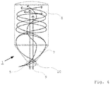
- der Reaktionstank gemäß
Figur 2 bei Betrieb sowohl der tangentialen als auch der vertikalen Einblasdüsen in einer seitlichen Schnittdarstellung, - Figur 5
- eine Dampfzuführung mit tangentialen und vertikalen Einblasdüsen in einer Draufsicht von oben, sowie
- Figur 6
- die Dampfzuführung gemäß
Figur 5 in einer perspektivischen Schnittdarstellung von schräg oben. -
Figur 1 zeigt eine Anlage zur Durchführung einer hydrothermalen Karbonisierung, welche einen Reaktionstank 1 umfasst, in welchem die eigentliche Karbonisierungsreaktion abläuft. Diesem Reaktionstank 1 wird über eine Biomassenzuführung 3 aus einem Vorheiztank 2 vorgeheizte Biomasse mit einer Temperatur von ca. 140°C zugeführt. Dies erfolgt über eine Biomassenpumpe 4. Gleichzeitig wird mithilfe einer Dampfpumpe 6 heißer Wasserdampf einer Dampfzuführung 5 des Reaktionstanks 1 zur Verfügung gestellt, so dass die Biomasse und der Dampf gleichzeitig in den Reaktionstank 1 eingebracht werden können. In dem Reaktionstank 1 werden hierdurch die Reaktionsbedingungen für den Ablauf der hydrothermalen Karbonisierung geschaffen, welche im Wesentlichen aus einem geeigneten Druck in Höhe von ca. 25 bar und einer geeigneten Temperatur in Höhe von ca. 210 bis 230°C bestehen. - Um sicherzustellen, dass die Biomasse möglichst gleichmäßig der hydrothermalen Karbonisierungsreaktion unterworfen wird, erfolgt eine Verteilung der Biomasse innerhalb des Reaktionstanks 1. Hierzu weist der Reaktionstank 1, welcher im Wesentlichen zylindrisch geformt ist und eine trichterförmige Ausbildung im Bodenbereich aufweist, welche in der Dampfzuführung 5 mündet, im Bereich dieser Dampfzuführung 5 vertikale Einblasdüsen 9 und tangentiale Einblasdüsen 10 auf.
- In
Figur 2 ist zunächst gezeigt, wie eine Verwirbelung der Biomasse durch den über die tangentialen Einblasdüsen 10 eingeblasenen Dampf erfolgt. Im Wesentlichen wird aufgrund dieser tangentialen Einblasdüsen 10 eine rotatorische Verwirbelung um die Längsachse des Reaktionstanks 1 herum stattfinden, wobei dieser Teil der Verwirbelung zu Beginn der Reaktion eingesetzt wird. Erst nach Einsetzen der eigentlichen Karbonisierung wird dann die in derFigur 3 gezeigte zweite Komponente zugeschaltet, nämlich das vertikale Einblasen von Dampf über vertikale Einblasdüsen 9. Während zunächst die rotatorische Verwirbelung in einem unteren Verwirbelungsbereich 7 des Reaktionstanks 1 stattgefunden hat, wird aufgrund dieser zusätzlichen, vertikalen Komponente der Verwirbelung eine größere Verteilung der reagierenden Biomasse in dem Reaktionstank 1 bewirkt, so dass auf diese Weise verschiedene energetische Potenziale in dem Behälter realisiert werden können. Durch die mit der vertikalen Verschiebung einhergehenden Dekompression kann die Karbonisierungsreaktion in dem oberen Reaktionsbereich 8 des Reaktors langsamer und gleichmäßiger ablaufen als in dem die Karbonisierungsreaktion initiierenden Verwirbelungsbereich 7, in dem sich die Biomasse nach Eintritt in den Reaktionstank 1 zunächst aufhält. Eine Überlagerung der beiden Verwirbelungskomponenten ist schließlich in derFigur 4 gezeigt. -
Figur 5 zeigt sodann eine Draufsicht auf die Dampfzuführung 5, welche im Wesentlichen schüsselförmig aufgebaut ist und im vorliegenden Beispiel insgesamt vier tangentiale Einblasdüsen 10 sowie vier vertikale Einblasdüsen 9 aufweist. Die als Venturi-Düsen ausgestalteten tangentialen Einblasdüsen 10 sind so ausgerichtet, dass ihre Einblasrichtung windschief zu einer Längsachse des Reaktionstanks 1 in vier unterschiedliche Richtungen verläuft. Im vorliegenden Beispiel strahlen sämtliche vier tangentialen Einblasdüsen 10 in einer gemeinsamen Ebene, jedoch ist es ohne Weiteres auch möglich, den tangentialen Einblasdüsen eine vertikalen Komponente mitzugeben, um eine bereits in diesem Stadium zumindest leicht nach oben gerichtete Verwirbelung zu erreichen.
Figur 6 zeigt deutlicher die vertikalen Einblasdüsen 9, welche im Wesentlichen parallel zu einer lotrecht stehenden Längsachse des Reaktionstanks 1 ausgerichtet sind. Die vertikalen Einblasdüsen 9 sind im Wesentlichen auf das Zentrum einer Verwirbelung ausgerichtet, welche um die Längsachse des Reaktionstanks 1 aufgrund der Wirkung der tangentialen Einblasdüsen 10 entsteht. Die vertikalen Einblasdüsen 9 werden bevorzugtermaßen erst dann zugeschaltet, wenn die Karbonisierungsreaktion durch die tangentialen Einblasdüsen 10 bereits begonnen hat.
Vorstehend beschrieben ist somit ein Verfahren und ein Reaktionstank zum Durchführen einer hydrothermalen Karbonisierungsreaktion, welche durch das Einblasen von Dampf mithilfe von vertikalen und tangentialen Einblasdüsen eine möglichst gleichmäßige, ideale Verteilung der Biomasse in dem Reaktionsraum und damit ein möglichst gleichmäßiges und ideales Ablaufen der Karbonisierungsreaktion ermöglichen. Insbesondere wird hierdurch ermöglicht, zwei verschiedene energetische Potenziale in einem Reaktionsraum zu realisieren und gleichzeitig die Durchmischung der Biomasse zu verbessern. Im Resultat wird dadurch das Ergebnis der Karbonisierungsreaktion sowohl beschleunigt als auch in der Qualität und Effizienz verbessert. -
- 1
- Reaktionstank
- 2
- Vorheiztank
- 3
- Biomassenzuführung
- 4
- Biomassenpumpe
- 5
- Dampfzuführung
- 6
- Dampfpumpe
- 7
- Verwirbelungsbereich
- 8
- Reaktionsbereich
- 9
- vertikale Einblasdüse
- 10
- tangentiale Einblasdüse
Claims (11)
- Verfahren zur Durchführung einer hydrothermalen Karbonisierungsreaktion, bei welchem einem Reaktionsraum Biomasse zugeführt und durch Einblasen von Dampf die für den Ablauf einer hydrothermalen Karbonisierungsreaktion erforderlichen Reaktionsbedingungen hinsichtlich Druck und Temperatur geschaffen werden,
dadurch gekennzeichnet, dass ein Dampfstrahl auf die Biomasse direkt gerichtet und diese in dem Reaktionsraum verwirbelt wird. - Verfahren gemäß Anspruch 1, dadurch gekennzeichnet, dass der Dampf mittels tangentialer Einblasdüsen (10) eingeblasen wird, deren Einblasrichtung windschief gegenüber einer vorzugsweise lotrecht stehenden Längsachse des Reaktionsraums verläuft.
- Verfahren gemäß Anspruch 1, dadurch gekennzeichnet, dass der Dampf mittels vertikaler Einblasdüsen (9) eingeblasen wird, deren Einblasrichtung parallel zu einer vorzugsweise lotrecht stehenden Längsachse des Reaktionsraums verläuft.
- Verfahren gemäß Anspruch 1, dadurch gekennzeichnet, dass zunächst Dampf mittels tangentialer Einblasdüsen (10) eingeblasen wird, deren Einblasrichtung windschief gegenüber einer vorzugsweise lotrecht stehenden Längsachse des Reaktionsraums verläuft und nach Einsetzen der Karbonisierungsreaktion vertikale Einblasdüsen (9), deren Einblasrichtung parallel zu der Längsachse des Reaktionsraums verläuft, zugeschaltet werden.
- Verfahren gemäß Anspruch 4, dadurch gekennzeichnet, dass die vertikalen Einblasdüsen (9) ausschließlich auf das Zentrum der von den tangentialen Einblasdüsen (10) verursachten Verwirbelung gerichtet sind.
- Verfahren gemäß einem der vorhergehenden Ansprüche, dadurch gekennzeichnet, dass der Dampf mit Überschallgeschwindigkeit, in den Reaktionsraum eingeblasen wird.
- Verfahren gemäß einem der vorhergehenden Ansprüche, dadurch gekennzeichnet, dass Dampf und Biomasse gleichzeitig in den Reaktionsraum eingebracht werden.
- Verfahren gemäß einem der vorhergehenden Ansprüche, dadurch gekennzeichnet, dass die Biomasse vor dem Einbringen in den Reaktionsraum auf zumindest näherungsweise 140°C vorgeheizt wird.
- Verfahren gemäß einem der vorhergehenden Ansprüche, dadurch gekennzeichnet, dass im Rahmen einer Parametrierung der Karbonisierungsreaktion die Vorheiztemperatur der Biomasse, die Einblasgeschwindigkeit des Dampfes, sowie die zeitliche und räumliche Verteilung des Dampfes auf verschiedene Einblasdüsen (9, 10), vorzugsweise über eine Prozesssteuerung, beeinflusst und/oder vorab festgelegt werden können.
- Reaktionstank einer Anlage zur hydrothermalen Karbonisierung von Biomasse, welcher einen Reaktionsraum mit Mitteln zur Zuführung von Biomasse (3) und Mitteln zur Zuführung von Dampf (5) umschließt, wobei die Mittel zur Zuführung von Dampf (5) wenigstens eine in einem bodennahen Verwirbelungsbereich (7) des Reaktionsraums angeordnete Einblasdüse (9, 10) zur Verwirbelung der Biomasse mithilfe des zuströmenden Dampfes umfassen
dadurch gekennzeichnet, dass die Mittel zur Zuführung von Dampf (5) wenigstens eine tangentiale Einblasdüse (10) umfassen, deren Einblasrichtung windschief gegenüber einer vorzugsweise lotrecht stehenden Längsachse des Reaktionsraums verläuft, sowie ferner wenigstens eine vertikale Einblasdüse (9) umfassen, deren Einblasrichtung parallel zu einer vorzugsweise lotrecht stehenden Längsachse des Reaktionsraums verläuft. - Reaktionstank gemäß Anspruch 10, dadurch gekennzeichnet, dass es sich bei den Einblasdüsen um Venturidüsen handelt.
Priority Applications (1)
| Application Number | Priority Date | Filing Date | Title |
|---|---|---|---|
| PL12714679T PL2697341T3 (pl) | 2011-04-11 | 2012-04-11 | Sposób przeprowadzania hydrotermalnej reakcji karbonizowania i przeznaczony do niej zbiornik reakcyjny |
Applications Claiming Priority (2)
| Application Number | Priority Date | Filing Date | Title |
|---|---|---|---|
| DE102011001954A DE102011001954B4 (de) | 2011-04-11 | 2011-04-11 | Verfahren zur Durchführung einer hydrothermalen Karbonisierungsreaktion und Reaktionstank hierfür |
| PCT/EP2012/056550 WO2012140060A1 (de) | 2011-04-11 | 2012-04-11 | Verfahren zur durchführung einer hydrothermalen karbonisierungsreaktion und reaktionstank hierfür |
Publications (2)
| Publication Number | Publication Date |
|---|---|
| EP2697341A1 EP2697341A1 (de) | 2014-02-19 |
| EP2697341B1 true EP2697341B1 (de) | 2018-11-14 |
Family
ID=45974328
Family Applications (1)
| Application Number | Title | Priority Date | Filing Date |
|---|---|---|---|
| EP12714679.3A Active EP2697341B1 (de) | 2011-04-11 | 2012-04-11 | Verfahren zur durchführung einer hydrothermalen karbonisierungsreaktion und reaktionstank hierfür |
Country Status (9)
| Country | Link |
|---|---|
| US (2) | US9238583B2 (de) |
| EP (1) | EP2697341B1 (de) |
| DE (2) | DE102011001954B4 (de) |
| DK (1) | DK2697341T3 (de) |
| ES (1) | ES2707610T3 (de) |
| HU (1) | HUE042315T2 (de) |
| PL (1) | PL2697341T3 (de) |
| TR (1) | TR201901158T4 (de) |
| WO (1) | WO2012140060A1 (de) |
Families Citing this family (6)
| Publication number | Priority date | Publication date | Assignee | Title |
|---|---|---|---|---|
| FR3037056B1 (fr) * | 2015-06-05 | 2019-11-29 | Degremont | Procede et dispositif de carbonisation hydrothermale a melange optimise de boue et vapeur |
| EP3363881B8 (de) | 2017-02-20 | 2020-08-19 | HTCycle AG | Verfahren zur durchführung einer hydrothermalen karbonisierungsreaktion |
| EP3372657B1 (de) | 2017-03-10 | 2019-09-25 | HTCycle GmbH | Vorrichtung zur durchführung einer hydrothermalen karbonisierungsreaktion |
| WO2019161272A1 (en) | 2018-02-15 | 2019-08-22 | North Carolina State University | Synthesis of micron and nanoscale carbon spheres and structures using hydrothemal carbonization |
| DE102021104733A1 (de) | 2021-02-26 | 2022-09-01 | Ipi.Ag | Beladene kohle und verfahren zu deren herstellung aus biomasse |
| DE102021105793A1 (de) | 2021-03-10 | 2022-09-15 | Ipi.Ag | Verfahren zur selektiven trennung und aufbereitung von stoffströmen aus einem hydrothermalen karbonisierungsprozess |
Citations (3)
| Publication number | Priority date | Publication date | Assignee | Title |
|---|---|---|---|---|
| US2890929A (en) * | 1954-12-31 | 1959-06-16 | Hoechst Ag | Process for carrying out exothermic chemical reactions |
| US4340566A (en) * | 1979-12-07 | 1982-07-20 | Uop Inc. | Catalyst regeneration apparatus |
| EP2681296A1 (de) * | 2011-03-04 | 2014-01-08 | AVA-Co2 Schweiz AG | Verfahren und vorrichtung zur hydrothermalen karbonisierung |
Family Cites Families (8)
| Publication number | Priority date | Publication date | Assignee | Title |
|---|---|---|---|---|
| GB1272227A (en) * | 1968-11-19 | 1972-04-26 | Ici Ltd | Injection method and apparatus therefor |
| US4435364A (en) | 1981-07-29 | 1984-03-06 | Institute Of Gas Technology | Fluidized bed gasifier or similar device for simultaneous classification of ash and unreacted coal |
| DE3139078A1 (de) * | 1981-10-01 | 1983-04-21 | Bergwerksverband Gmbh, 4300 Essen | Verfahren zur regeneration von feuchten, pulverfoermigen adsorptionsmitteln sowie vorrichtung zur durchfuehrung dieses verfahrens |
| DE102007022840A1 (de) | 2007-05-11 | 2008-12-24 | Suncoal Industries Gmbh | Verfahren zur Kühlung und Vorwärmung einer Anlage zur hydrothermalen Carbonisierung von Biomasse |
| US20090064580A1 (en) | 2007-09-12 | 2009-03-12 | Nicoll David H | Venturi inserts, interchangeable venturis, and methods of fluidizing |
| US8309052B2 (en) * | 2009-07-02 | 2012-11-13 | Pneumatic Processing Technologies, L.L.C. | Carbon heat-treatment process |
| RU2011132925A (ru) | 2009-02-10 | 2013-03-20 | Ссл Карбон Солюшнс Лтд. | Гидротермический способ получения углеподобного материала из биомассы и испарительная колонна |
| DE102009010233B4 (de) * | 2009-02-24 | 2020-06-10 | Revatec Gmbh | Verfahren zum Erzeugen von Kohle aus Biomasse |
-
2011
- 2011-04-11 DE DE102011001954A patent/DE102011001954B4/de not_active Expired - Fee Related
- 2011-04-11 DE DE202011110245U patent/DE202011110245U1/de not_active Expired - Lifetime
-
2012
- 2012-04-11 TR TR2019/01158T patent/TR201901158T4/tr unknown
- 2012-04-11 EP EP12714679.3A patent/EP2697341B1/de active Active
- 2012-04-11 WO PCT/EP2012/056550 patent/WO2012140060A1/de not_active Ceased
- 2012-04-11 HU HUE12714679A patent/HUE042315T2/hu unknown
- 2012-04-11 ES ES12714679T patent/ES2707610T3/es active Active
- 2012-04-11 US US14/009,504 patent/US9238583B2/en not_active Expired - Fee Related
- 2012-04-11 PL PL12714679T patent/PL2697341T3/pl unknown
- 2012-04-11 DK DK12714679.3T patent/DK2697341T3/en active
-
2015
- 2015-08-14 US US14/826,734 patent/US9637383B2/en active Active
Patent Citations (3)
| Publication number | Priority date | Publication date | Assignee | Title |
|---|---|---|---|---|
| US2890929A (en) * | 1954-12-31 | 1959-06-16 | Hoechst Ag | Process for carrying out exothermic chemical reactions |
| US4340566A (en) * | 1979-12-07 | 1982-07-20 | Uop Inc. | Catalyst regeneration apparatus |
| EP2681296A1 (de) * | 2011-03-04 | 2014-01-08 | AVA-Co2 Schweiz AG | Verfahren und vorrichtung zur hydrothermalen karbonisierung |
Also Published As
| Publication number | Publication date |
|---|---|
| WO2012140060A1 (de) | 2012-10-18 |
| US20150368104A1 (en) | 2015-12-24 |
| HUE042315T2 (hu) | 2019-06-28 |
| ES2707610T3 (es) | 2019-04-04 |
| TR201901158T4 (tr) | 2019-02-21 |
| US20140023580A1 (en) | 2014-01-23 |
| DE102011001954B4 (de) | 2013-05-08 |
| DK2697341T3 (en) | 2019-03-04 |
| EP2697341A1 (de) | 2014-02-19 |
| PL2697341T3 (pl) | 2019-09-30 |
| DE102011001954A1 (de) | 2012-10-11 |
| DE202011110245U1 (de) | 2013-04-24 |
| US9238583B2 (en) | 2016-01-19 |
| US9637383B2 (en) | 2017-05-02 |
Similar Documents
| Publication | Publication Date | Title |
|---|---|---|
| DE102011001954B4 (de) | Verfahren zur Durchführung einer hydrothermalen Karbonisierungsreaktion und Reaktionstank hierfür | |
| EP2681296B1 (de) | Verfahren und vorrichtung zur hydrothermalen karbonisierung | |
| DE69122890T2 (de) | Plasmafackel | |
| EP3372657B1 (de) | Vorrichtung zur durchführung einer hydrothermalen karbonisierungsreaktion | |
| EP2775240B1 (de) | Vorrichtung zum Behandeln einer Beschichtung einer Fahrzeugkarosserie | |
| EP2123613A1 (de) | Verfahren und Anlage zur Kalzinierung von Phosphorgips | |
| DE1185305B (de) | Verfahren zum Loeten, Schweissen und Abtragen von Materialien mittels eines Ladungstraegerstrahls | |
| DE102018109830A1 (de) | Verfahren und Vorrichtung zum Entpulvern eines Bauraums | |
| DE2062794C3 (de) | Verfahren und Vorrichtung zum Beschichten von Brennstoffteilchen für Kernreaktoren | |
| EP0793531B1 (de) | Verfahren zum chemischen modifizieren von alkylgruppenhaltigen feststoffen | |
| EP3122463B1 (de) | Verfahren zum fragmentieren eines stangenartigen materials, insbesondere aus polykristallinem silizium | |
| DE1792540C2 (de) | Verfahren und Anlage zum Aufschließen einer Holzschnitzelpartie in einem kontinuierlich arbeitenden Zellstoffkocher | |
| EP3323597B1 (de) | Vorrichtung und verfahren zur additiven herstellung eines dreidimensionalen produktes | |
| DE69201051T3 (de) | Verfahren und vorrichtung zum anbringen einer isolierschicht an der oberflaeche eines gegenstandes. | |
| DE2824374A1 (de) | Verfahren und vorrichtung zum mischen von feinen sowie bindigen pulvern in einem wirbelbett mit hilfe einer gaseinfuehrung durch kugelventile | |
| EP1208243B1 (de) | Verfahren zum härten mindestens einer fläche einer wand eines bauteils und vorrichtung zu seiner durchführung | |
| EP0784039B1 (de) | Verfahren und Vorrichtung zum Abbau von organischem Material | |
| EP2107862A1 (de) | Verfahren und Vorrichtung zur Behandlung von Dispersionsmaterialien | |
| CH630948A5 (de) | Anlage zur russherstellung. | |
| DE69610720T2 (de) | Fluidatbettartiges system zum reduzieren von feinem eisenerz | |
| AT516103B1 (de) | Vorrichtung und Verfahren zur insbesondere kontinuierlichen thermischen Behandlung einer Stärkesuspension | |
| EP0774635A1 (de) | Ringschachtofen | |
| EP2512737B1 (de) | Verfahren und vorrichtung zum reinigen, aktivieren und vorbehandeln eines werkstücks mittels kohlendioxidschneepartikeln | |
| DE2200448A1 (de) | Verfahren und Vorrichtung zur Waermebehandlung schwer schmelzbarer Materialien im Wirbelschichtbett | |
| AT515771B1 (de) | Vorrichtung und Verfahren zum Nachrösten von Metalloxiden |
Legal Events
| Date | Code | Title | Description |
|---|---|---|---|
| PUAI | Public reference made under article 153(3) epc to a published international application that has entered the european phase |
Free format text: ORIGINAL CODE: 0009012 |
|
| 17P | Request for examination filed |
Effective date: 20131015 |
|
| AK | Designated contracting states |
Kind code of ref document: A1 Designated state(s): AL AT BE BG CH CY CZ DE DK EE ES FI FR GB GR HR HU IE IS IT LI LT LU LV MC MK MT NL NO PL PT RO RS SE SI SK SM TR |
|
| DAX | Request for extension of the european patent (deleted) | ||
| STAA | Information on the status of an ep patent application or granted ep patent |
Free format text: STATUS: EXAMINATION IS IN PROGRESS |
|
| 17Q | First examination report despatched |
Effective date: 20161025 |
|
| RAP1 | Party data changed (applicant data changed or rights of an application transferred) |
Owner name: AVALON INDUSTRIES AG |
|
| GRAP | Despatch of communication of intention to grant a patent |
Free format text: ORIGINAL CODE: EPIDOSNIGR1 |
|
| STAA | Information on the status of an ep patent application or granted ep patent |
Free format text: STATUS: GRANT OF PATENT IS INTENDED |
|
| RIC1 | Information provided on ipc code assigned before grant |
Ipc: C01B 32/05 20170101ALI20180620BHEP Ipc: C10L 9/08 20060101AFI20180620BHEP |
|
| INTG | Intention to grant announced |
Effective date: 20180704 |
|
| GRAS | Grant fee paid |
Free format text: ORIGINAL CODE: EPIDOSNIGR3 |
|
| GRAA | (expected) grant |
Free format text: ORIGINAL CODE: 0009210 |
|
| STAA | Information on the status of an ep patent application or granted ep patent |
Free format text: STATUS: THE PATENT HAS BEEN GRANTED |
|
| AK | Designated contracting states |
Kind code of ref document: B1 Designated state(s): AL AT BE BG CH CY CZ DE DK EE ES FI FR GB GR HR HU IE IS IT LI LT LU LV MC MK MT NL NO PL PT RO RS SE SI SK SM TR |
|
| REG | Reference to a national code |
Ref country code: CH Ref legal event code: EP Ref country code: AT Ref legal event code: REF Ref document number: 1064815 Country of ref document: AT Kind code of ref document: T Effective date: 20181115 |
|
| REG | Reference to a national code |
Ref country code: DE Ref legal event code: R096 Ref document number: 502012013816 Country of ref document: DE |
|
| REG | Reference to a national code |
Ref country code: IE Ref legal event code: FG4D Free format text: LANGUAGE OF EP DOCUMENT: GERMAN |
|
| REG | Reference to a national code |
Ref country code: DE Ref legal event code: R081 Ref document number: 502012013816 Country of ref document: DE Owner name: AVA BIOCHEM AG, CH Free format text: FORMER OWNER: AVALON INDUSTRIES AG, ZUG, CH |
|
| REG | Reference to a national code |
Ref country code: RO Ref legal event code: EPE |
|
| REG | Reference to a national code |
Ref country code: CH Ref legal event code: NV Representative=s name: OFFICE ERNEST T. FREYLINGER S.A., CH |
|
| REG | Reference to a national code |
Ref country code: SE Ref legal event code: TRGR |
|
| RAP2 | Party data changed (patent owner data changed or rights of a patent transferred) |
Owner name: AVA BIOCHEM AG |
|
| REG | Reference to a national code |
Ref country code: HU Ref legal event code: HC9C Owner name: AVA BIOCHEM AG, CH Free format text: FORMER OWNER(S): AVALON INDUSTRIES AG, CH |
|
| REG | Reference to a national code |
Ref country code: DK Ref legal event code: T3 Effective date: 20190225 |
|
| REG | Reference to a national code |
Ref country code: NO Ref legal event code: T2 Effective date: 20181114 |
|
| REG | Reference to a national code |
Ref country code: NL Ref legal event code: FP |
|
| REG | Reference to a national code |
Ref country code: LT Ref legal event code: MG4D |
|
| REG | Reference to a national code |
Ref country code: ES Ref legal event code: FG2A Ref document number: 2707610 Country of ref document: ES Kind code of ref document: T3 Effective date: 20190404 |
|
| PG25 | Lapsed in a contracting state [announced via postgrant information from national office to epo] |
Ref country code: LT Free format text: LAPSE BECAUSE OF FAILURE TO SUBMIT A TRANSLATION OF THE DESCRIPTION OR TO PAY THE FEE WITHIN THE PRESCRIBED TIME-LIMIT Effective date: 20181114 Ref country code: IS Free format text: LAPSE BECAUSE OF FAILURE TO SUBMIT A TRANSLATION OF THE DESCRIPTION OR TO PAY THE FEE WITHIN THE PRESCRIBED TIME-LIMIT Effective date: 20190314 Ref country code: HR Free format text: LAPSE BECAUSE OF FAILURE TO SUBMIT A TRANSLATION OF THE DESCRIPTION OR TO PAY THE FEE WITHIN THE PRESCRIBED TIME-LIMIT Effective date: 20181114 Ref country code: LV Free format text: LAPSE BECAUSE OF FAILURE TO SUBMIT A TRANSLATION OF THE DESCRIPTION OR TO PAY THE FEE WITHIN THE PRESCRIBED TIME-LIMIT Effective date: 20181114 |
|
| REG | Reference to a national code |
Ref country code: BE Ref legal event code: HC Owner name: AVA BIOCHEM AG; CH Free format text: DETAILS ASSIGNMENT: CHANGE OF OWNER(S), CHANGEMENT DE NOM DU PROPRIETAIRE, NOM/ADRESSE; FORMER OWNER NAME: AVALON INDUSTRIES AG Effective date: 20190213 |
|
| PG25 | Lapsed in a contracting state [announced via postgrant information from national office to epo] |
Ref country code: RS Free format text: LAPSE BECAUSE OF FAILURE TO SUBMIT A TRANSLATION OF THE DESCRIPTION OR TO PAY THE FEE WITHIN THE PRESCRIBED TIME-LIMIT Effective date: 20181114 Ref country code: AL Free format text: LAPSE BECAUSE OF FAILURE TO SUBMIT A TRANSLATION OF THE DESCRIPTION OR TO PAY THE FEE WITHIN THE PRESCRIBED TIME-LIMIT Effective date: 20181114 Ref country code: PT Free format text: LAPSE BECAUSE OF FAILURE TO SUBMIT A TRANSLATION OF THE DESCRIPTION OR TO PAY THE FEE WITHIN THE PRESCRIBED TIME-LIMIT Effective date: 20190314 |
|
| REG | Reference to a national code |
Ref country code: GR Ref legal event code: EP Ref document number: 20190400470 Country of ref document: GR Effective date: 20190509 |
|
| REG | Reference to a national code |
Ref country code: HU Ref legal event code: AG4A Ref document number: E042315 Country of ref document: HU |
|
| REG | Reference to a national code |
Ref country code: AT Ref legal event code: HC Ref document number: 1064815 Country of ref document: AT Kind code of ref document: T Owner name: AVA BIOCHEM AG, CH Effective date: 20190517 |
|
| REG | Reference to a national code |
Ref country code: DE Ref legal event code: R097 Ref document number: 502012013816 Country of ref document: DE |
|
| PG25 | Lapsed in a contracting state [announced via postgrant information from national office to epo] |
Ref country code: SM Free format text: LAPSE BECAUSE OF FAILURE TO SUBMIT A TRANSLATION OF THE DESCRIPTION OR TO PAY THE FEE WITHIN THE PRESCRIBED TIME-LIMIT Effective date: 20181114 Ref country code: EE Free format text: LAPSE BECAUSE OF FAILURE TO SUBMIT A TRANSLATION OF THE DESCRIPTION OR TO PAY THE FEE WITHIN THE PRESCRIBED TIME-LIMIT Effective date: 20181114 Ref country code: SK Free format text: LAPSE BECAUSE OF FAILURE TO SUBMIT A TRANSLATION OF THE DESCRIPTION OR TO PAY THE FEE WITHIN THE PRESCRIBED TIME-LIMIT Effective date: 20181114 |
|
| PLBE | No opposition filed within time limit |
Free format text: ORIGINAL CODE: 0009261 |
|
| STAA | Information on the status of an ep patent application or granted ep patent |
Free format text: STATUS: NO OPPOSITION FILED WITHIN TIME LIMIT |
|
| 26N | No opposition filed |
Effective date: 20190815 |
|
| PG25 | Lapsed in a contracting state [announced via postgrant information from national office to epo] |
Ref country code: SI Free format text: LAPSE BECAUSE OF FAILURE TO SUBMIT A TRANSLATION OF THE DESCRIPTION OR TO PAY THE FEE WITHIN THE PRESCRIBED TIME-LIMIT Effective date: 20181114 |
|
| PG25 | Lapsed in a contracting state [announced via postgrant information from national office to epo] |
Ref country code: MC Free format text: LAPSE BECAUSE OF FAILURE TO SUBMIT A TRANSLATION OF THE DESCRIPTION OR TO PAY THE FEE WITHIN THE PRESCRIBED TIME-LIMIT Effective date: 20181114 Ref country code: LU Free format text: LAPSE BECAUSE OF NON-PAYMENT OF DUE FEES Effective date: 20190411 |
|
| PG25 | Lapsed in a contracting state [announced via postgrant information from national office to epo] |
Ref country code: IE Free format text: LAPSE BECAUSE OF NON-PAYMENT OF DUE FEES Effective date: 20190411 |
|
| REG | Reference to a national code |
Ref country code: HU Ref legal event code: HC9C Owner name: AVA BIOCHEM AG, CH Free format text: FORMER OWNER(S): AVALON INDUSTRIES AG, CH |
|
| PG25 | Lapsed in a contracting state [announced via postgrant information from national office to epo] |
Ref country code: CY Free format text: LAPSE BECAUSE OF FAILURE TO SUBMIT A TRANSLATION OF THE DESCRIPTION OR TO PAY THE FEE WITHIN THE PRESCRIBED TIME-LIMIT Effective date: 20181114 |
|
| PG25 | Lapsed in a contracting state [announced via postgrant information from national office to epo] |
Ref country code: MT Free format text: LAPSE BECAUSE OF FAILURE TO SUBMIT A TRANSLATION OF THE DESCRIPTION OR TO PAY THE FEE WITHIN THE PRESCRIBED TIME-LIMIT Effective date: 20181114 |
|
| PGFP | Annual fee paid to national office [announced via postgrant information from national office to epo] |
Ref country code: GR Payment date: 20210420 Year of fee payment: 10 Ref country code: CZ Payment date: 20210429 Year of fee payment: 10 Ref country code: RO Payment date: 20210429 Year of fee payment: 10 |
|
| PGFP | Annual fee paid to national office [announced via postgrant information from national office to epo] |
Ref country code: TR Payment date: 20210429 Year of fee payment: 10 Ref country code: HU Payment date: 20210502 Year of fee payment: 10 Ref country code: PL Payment date: 20210428 Year of fee payment: 10 Ref country code: DK Payment date: 20210420 Year of fee payment: 10 Ref country code: BG Payment date: 20210505 Year of fee payment: 10 |
|
| PG25 | Lapsed in a contracting state [announced via postgrant information from national office to epo] |
Ref country code: MK Free format text: LAPSE BECAUSE OF FAILURE TO SUBMIT A TRANSLATION OF THE DESCRIPTION OR TO PAY THE FEE WITHIN THE PRESCRIBED TIME-LIMIT Effective date: 20181114 |
|
| PGFP | Annual fee paid to national office [announced via postgrant information from national office to epo] |
Ref country code: NL Payment date: 20220428 Year of fee payment: 11 |
|
| PGFP | Annual fee paid to national office [announced via postgrant information from national office to epo] |
Ref country code: SE Payment date: 20220428 Year of fee payment: 11 Ref country code: NO Payment date: 20220520 Year of fee payment: 11 Ref country code: IT Payment date: 20220429 Year of fee payment: 11 Ref country code: GB Payment date: 20220523 Year of fee payment: 11 Ref country code: FR Payment date: 20220428 Year of fee payment: 11 Ref country code: ES Payment date: 20220518 Year of fee payment: 11 Ref country code: DE Payment date: 20220519 Year of fee payment: 11 |
|
| PGFP | Annual fee paid to national office [announced via postgrant information from national office to epo] |
Ref country code: FI Payment date: 20220429 Year of fee payment: 11 Ref country code: CH Payment date: 20220523 Year of fee payment: 11 Ref country code: BE Payment date: 20220428 Year of fee payment: 11 Ref country code: AT Payment date: 20220428 Year of fee payment: 11 |
|
| REG | Reference to a national code |
Ref country code: HU Ref legal event code: HC9C Owner name: AVA BIOCHEM AG, CH Free format text: FORMER OWNER(S): AVALON INDUSTRIES AG, CH |
|
| PG25 | Lapsed in a contracting state [announced via postgrant information from national office to epo] |
Ref country code: CZ Free format text: LAPSE BECAUSE OF NON-PAYMENT OF DUE FEES Effective date: 20220411 |
|
| REG | Reference to a national code |
Ref country code: DK Ref legal event code: EBP Effective date: 20220430 |
|
| PG25 | Lapsed in a contracting state [announced via postgrant information from national office to epo] |
Ref country code: RO Free format text: LAPSE BECAUSE OF NON-PAYMENT OF DUE FEES Effective date: 20220411 Ref country code: HU Free format text: LAPSE BECAUSE OF NON-PAYMENT OF DUE FEES Effective date: 20220412 |
|
| PG25 | Lapsed in a contracting state [announced via postgrant information from national office to epo] |
Ref country code: GR Free format text: LAPSE BECAUSE OF NON-PAYMENT OF DUE FEES Effective date: 20221107 |
|
| PG25 | Lapsed in a contracting state [announced via postgrant information from national office to epo] |
Ref country code: DK Free format text: LAPSE BECAUSE OF NON-PAYMENT OF DUE FEES Effective date: 20220430 |
|
| REG | Reference to a national code |
Ref country code: DE Ref legal event code: R119 Ref document number: 502012013816 Country of ref document: DE |
|
| REG | Reference to a national code |
Ref country code: NO Ref legal event code: MMEP |
|
| REG | Reference to a national code |
Ref country code: SE Ref legal event code: EUG |
|
| REG | Reference to a national code |
Ref country code: CH Ref legal event code: PL |
|
| REG | Reference to a national code |
Ref country code: NL Ref legal event code: MM Effective date: 20230501 |
|
| REG | Reference to a national code |
Ref country code: AT Ref legal event code: MM01 Ref document number: 1064815 Country of ref document: AT Kind code of ref document: T Effective date: 20230411 |
|
| GBPC | Gb: european patent ceased through non-payment of renewal fee |
Effective date: 20230411 |
|
| REG | Reference to a national code |
Ref country code: BE Ref legal event code: MM Effective date: 20230430 |
|
| PG25 | Lapsed in a contracting state [announced via postgrant information from national office to epo] |
Ref country code: GB Free format text: LAPSE BECAUSE OF NON-PAYMENT OF DUE FEES Effective date: 20230411 |
|
| PG25 | Lapsed in a contracting state [announced via postgrant information from national office to epo] |
Ref country code: SE Free format text: LAPSE BECAUSE OF NON-PAYMENT OF DUE FEES Effective date: 20230412 Ref country code: NO Free format text: LAPSE BECAUSE OF NON-PAYMENT OF DUE FEES Effective date: 20230430 Ref country code: NL Free format text: LAPSE BECAUSE OF NON-PAYMENT OF DUE FEES Effective date: 20230501 Ref country code: LI Free format text: LAPSE BECAUSE OF NON-PAYMENT OF DUE FEES Effective date: 20230430 Ref country code: GB Free format text: LAPSE BECAUSE OF NON-PAYMENT OF DUE FEES Effective date: 20230411 Ref country code: FR Free format text: LAPSE BECAUSE OF NON-PAYMENT OF DUE FEES Effective date: 20230430 Ref country code: FI Free format text: LAPSE BECAUSE OF NON-PAYMENT OF DUE FEES Effective date: 20230411 Ref country code: DE Free format text: LAPSE BECAUSE OF NON-PAYMENT OF DUE FEES Effective date: 20231103 Ref country code: CH Free format text: LAPSE BECAUSE OF NON-PAYMENT OF DUE FEES Effective date: 20230430 Ref country code: AT Free format text: LAPSE BECAUSE OF NON-PAYMENT OF DUE FEES Effective date: 20230411 |
|
| PG25 | Lapsed in a contracting state [announced via postgrant information from national office to epo] |
Ref country code: PL Free format text: LAPSE BECAUSE OF NON-PAYMENT OF DUE FEES Effective date: 20220411 Ref country code: BE Free format text: LAPSE BECAUSE OF NON-PAYMENT OF DUE FEES Effective date: 20230430 |
|
| PG25 | Lapsed in a contracting state [announced via postgrant information from national office to epo] |
Ref country code: IT Free format text: LAPSE BECAUSE OF NON-PAYMENT OF DUE FEES Effective date: 20230411 |
|
| REG | Reference to a national code |
Ref country code: ES Ref legal event code: FD2A Effective date: 20240531 |
|
| PG25 | Lapsed in a contracting state [announced via postgrant information from national office to epo] |
Ref country code: ES Free format text: LAPSE BECAUSE OF NON-PAYMENT OF DUE FEES Effective date: 20230412 |
|
| PG25 | Lapsed in a contracting state [announced via postgrant information from national office to epo] |
Ref country code: ES Free format text: LAPSE BECAUSE OF NON-PAYMENT OF DUE FEES Effective date: 20230412 Ref country code: BG Free format text: LAPSE BECAUSE OF NON-PAYMENT OF DUE FEES Effective date: 20220411 |