EP2696670B1 - Automated gravimetric screening platform system and method - Google Patents
Automated gravimetric screening platform system and method Download PDFInfo
- Publication number
- EP2696670B1 EP2696670B1 EP12715283.3A EP12715283A EP2696670B1 EP 2696670 B1 EP2696670 B1 EP 2696670B1 EP 12715283 A EP12715283 A EP 12715283A EP 2696670 B1 EP2696670 B1 EP 2696670B1
- Authority
- EP
- European Patent Office
- Prior art keywords
- pots
- load cell
- platform
- pot
- support
- Prior art date
- Legal status (The legal status is an assumption and is not a legal conclusion. Google has not performed a legal analysis and makes no representation as to the accuracy of the status listed.)
- Not-in-force
Links
- 238000000034 method Methods 0.000 title claims description 28
- 238000012216 screening Methods 0.000 title description 20
- XLYOFNOQVPJJNP-UHFFFAOYSA-N water Substances O XLYOFNOQVPJJNP-UHFFFAOYSA-N 0.000 claims description 71
- 239000012530 fluid Substances 0.000 claims description 46
- 241000196324 Embryophyta Species 0.000 claims description 36
- 238000002474 experimental method Methods 0.000 claims description 29
- 239000002689 soil Substances 0.000 claims description 25
- 238000005303 weighing Methods 0.000 claims description 14
- 230000006735 deficit Effects 0.000 claims description 13
- 230000007246 mechanism Effects 0.000 claims description 12
- 238000004891 communication Methods 0.000 claims description 9
- 239000008400 supply water Substances 0.000 claims description 7
- 238000013459 approach Methods 0.000 claims description 2
- 230000008569 process Effects 0.000 description 5
- 229920001296 polysiloxane Polymers 0.000 description 4
- 239000000463 material Substances 0.000 description 3
- 235000015097 nutrients Nutrition 0.000 description 3
- IJGRMHOSHXDMSA-UHFFFAOYSA-N Atomic nitrogen Chemical compound N#N IJGRMHOSHXDMSA-UHFFFAOYSA-N 0.000 description 2
- 208000005156 Dehydration Diseases 0.000 description 2
- 238000013461 design Methods 0.000 description 2
- 230000003068 static effect Effects 0.000 description 2
- 230000035882 stress Effects 0.000 description 2
- 229920002994 synthetic fiber Polymers 0.000 description 2
- 238000012360 testing method Methods 0.000 description 2
- 238000001931 thermography Methods 0.000 description 2
- 238000009825 accumulation Methods 0.000 description 1
- 230000006978 adaptation Effects 0.000 description 1
- 230000004075 alteration Effects 0.000 description 1
- 230000004888 barrier function Effects 0.000 description 1
- 238000011161 development Methods 0.000 description 1
- 238000010586 diagram Methods 0.000 description 1
- 230000008641 drought stress Effects 0.000 description 1
- 230000000694 effects Effects 0.000 description 1
- 238000005259 measurement Methods 0.000 description 1
- 238000012986 modification Methods 0.000 description 1
- 230000004048 modification Effects 0.000 description 1
- 238000012544 monitoring process Methods 0.000 description 1
- 229910052757 nitrogen Inorganic materials 0.000 description 1
- 238000009428 plumbing Methods 0.000 description 1
- 230000001737 promoting effect Effects 0.000 description 1
- 238000007789 sealing Methods 0.000 description 1
- 238000012956 testing procedure Methods 0.000 description 1
- 230000005068 transpiration Effects 0.000 description 1
- 230000000007 visual effect Effects 0.000 description 1
Images






Classifications
-
- A—HUMAN NECESSITIES
- A01—AGRICULTURE; FORESTRY; ANIMAL HUSBANDRY; HUNTING; TRAPPING; FISHING
- A01G—HORTICULTURE; CULTIVATION OF VEGETABLES, FLOWERS, RICE, FRUIT, VINES, HOPS OR SEAWEED; FORESTRY; WATERING
- A01G27/00—Self-acting watering devices, e.g. for flower-pots
- A01G27/003—Control of self-acting watering devices
-
- A—HUMAN NECESSITIES
- A01—AGRICULTURE; FORESTRY; ANIMAL HUSBANDRY; HUNTING; TRAPPING; FISHING
- A01G—HORTICULTURE; CULTIVATION OF VEGETABLES, FLOWERS, RICE, FRUIT, VINES, HOPS OR SEAWEED; FORESTRY; WATERING
- A01G25/00—Watering gardens, fields, sports grounds or the like
- A01G25/16—Control of watering
- A01G25/167—Control by humidity of the soil itself or of devices simulating soil or of the atmosphere; Soil humidity sensors
-
- A—HUMAN NECESSITIES
- A01—AGRICULTURE; FORESTRY; ANIMAL HUSBANDRY; HUNTING; TRAPPING; FISHING
- A01G—HORTICULTURE; CULTIVATION OF VEGETABLES, FLOWERS, RICE, FRUIT, VINES, HOPS OR SEAWEED; FORESTRY; WATERING
- A01G27/00—Self-acting watering devices, e.g. for flower-pots
- A01G27/02—Self-acting watering devices, e.g. for flower-pots having a water reservoir, the main part thereof being located wholly around or directly beside the growth substrate
-
- A—HUMAN NECESSITIES
- A01—AGRICULTURE; FORESTRY; ANIMAL HUSBANDRY; HUNTING; TRAPPING; FISHING
- A01G—HORTICULTURE; CULTIVATION OF VEGETABLES, FLOWERS, RICE, FRUIT, VINES, HOPS OR SEAWEED; FORESTRY; WATERING
- A01G7/00—Botany in general
-
- A—HUMAN NECESSITIES
- A01—AGRICULTURE; FORESTRY; ANIMAL HUSBANDRY; HUNTING; TRAPPING; FISHING
- A01G—HORTICULTURE; CULTIVATION OF VEGETABLES, FLOWERS, RICE, FRUIT, VINES, HOPS OR SEAWEED; FORESTRY; WATERING
- A01G9/00—Cultivation in receptacles, forcing-frames or greenhouses; Edging for beds, lawn or the like
- A01G9/02—Receptacles, e.g. flower-pots or boxes; Glasses for cultivating flowers
-
- A—HUMAN NECESSITIES
- A01—AGRICULTURE; FORESTRY; ANIMAL HUSBANDRY; HUNTING; TRAPPING; FISHING
- A01G—HORTICULTURE; CULTIVATION OF VEGETABLES, FLOWERS, RICE, FRUIT, VINES, HOPS OR SEAWEED; FORESTRY; WATERING
- A01G9/00—Cultivation in receptacles, forcing-frames or greenhouses; Edging for beds, lawn or the like
- A01G9/08—Devices for filling-up flower-pots or pots for seedlings; Devices for setting plants or seeds in pots
- A01G9/088—Handling or transferring pots
-
- A—HUMAN NECESSITIES
- A01—AGRICULTURE; FORESTRY; ANIMAL HUSBANDRY; HUNTING; TRAPPING; FISHING
- A01G—HORTICULTURE; CULTIVATION OF VEGETABLES, FLOWERS, RICE, FRUIT, VINES, HOPS OR SEAWEED; FORESTRY; WATERING
- A01G9/00—Cultivation in receptacles, forcing-frames or greenhouses; Edging for beds, lawn or the like
- A01G9/24—Devices or systems for heating, ventilating, regulating temperature, illuminating, or watering, in greenhouses, forcing-frames, or the like
- A01G9/247—Watering arrangements
-
- A—HUMAN NECESSITIES
- A01—AGRICULTURE; FORESTRY; ANIMAL HUSBANDRY; HUNTING; TRAPPING; FISHING
- A01G—HORTICULTURE; CULTIVATION OF VEGETABLES, FLOWERS, RICE, FRUIT, VINES, HOPS OR SEAWEED; FORESTRY; WATERING
- A01G9/00—Cultivation in receptacles, forcing-frames or greenhouses; Edging for beds, lawn or the like
- A01G9/14—Greenhouses
- A01G9/143—Equipment for handling produce in greenhouses
-
- Y—GENERAL TAGGING OF NEW TECHNOLOGICAL DEVELOPMENTS; GENERAL TAGGING OF CROSS-SECTIONAL TECHNOLOGIES SPANNING OVER SEVERAL SECTIONS OF THE IPC; TECHNICAL SUBJECTS COVERED BY FORMER USPC CROSS-REFERENCE ART COLLECTIONS [XRACs] AND DIGESTS
- Y02—TECHNOLOGIES OR APPLICATIONS FOR MITIGATION OR ADAPTATION AGAINST CLIMATE CHANGE
- Y02A—TECHNOLOGIES FOR ADAPTATION TO CLIMATE CHANGE
- Y02A40/00—Adaptation technologies in agriculture, forestry, livestock or agroalimentary production
- Y02A40/10—Adaptation technologies in agriculture, forestry, livestock or agroalimentary production in agriculture
- Y02A40/25—Greenhouse technology, e.g. cooling systems therefor
Definitions
- the gravimetric screening platform system 10 and method of the present disclosure maintains the pots 16 at static locations throughout an experiment without requiring the pots 16 to be moved to a different location for weighing, testing and re-watering. While one row 38 of pots is lifted at a time in the illustrated embodiments, multiple rows 38 may be lifted simultaneously in other embodiments.
Landscapes
- Life Sciences & Earth Sciences (AREA)
- Environmental Sciences (AREA)
- Engineering & Computer Science (AREA)
- Water Supply & Treatment (AREA)
- Botany (AREA)
- Biodiversity & Conservation Biology (AREA)
- Ecology (AREA)
- Forests & Forestry (AREA)
- Soil Sciences (AREA)
- Cultivation Receptacles Or Flower-Pots, Or Pots For Seedlings (AREA)
- Investigating Strength Of Materials By Application Of Mechanical Stress (AREA)
- Cultivation Of Plants (AREA)
- Investigating Or Analyzing Materials Using Thermal Means (AREA)
- Investigation Of Foundation Soil And Reinforcement Of Foundation Soil By Compacting Or Drainage (AREA)
- Investigating Or Analysing Materials By Optical Means (AREA)
Description
- The present disclosure relates to a system and method for providing controlled soil moisture conditions within potted plants in a large-scale, automated gravimetric screening system, typically located in a greenhouse.
- The gravimetric method is a known technique of imposing a precision drought stress regime on plants growing in containers or pots by measuring changes in the mass of the pot. Measuring the pot mass provides an accurate calculation of changes in soil moisture, and rewater values are determined by calculating the difference between the actual water content and the desired water content based on a predetermined water deficit program. With appropriate control of evaporative water loss from the soil, the gravimetric method allows for determination of plant transpiration and total plant water use through the duration of an experiment.
- Typically, gravimetric screening is a highly labor intensive process that limits throughput and capacity in screening specific programs. Conventional screening systems move individual pots to a weighing and re-watering station. In some cases, entire blocks of plants are moved as a unit to another location for weight measurements and re-watering. This movement introduces additional confounding effects to testing procedures such as vibrations during movement and low density growth conditions, for example, which are not typical in field environments. These known gravimetric screening systems do not make the most efficient use of greenhouse space.
-
US 2010/031568 discloses a container watering system, the container comprising a fluid reservoir having a bottom portion and vertically extending fluid channels. - Further,
DD 285 919 SU 952 167 - The automated gravimetric screening system and method of the present disclosure provides a high throughput greenhouse screening system using a support platform and pot design that maintains the plants in a static location during the testing. The system includes a lower gantry located below the support platform which has a plurality of independent load cell modules and plumbing to weigh and supply water to each row of pots. In an illustrated embodiment, each row of pots is lifted simultaneously by the load cell modules to acquire weights, calculate how much water should be added to bring the pot to a desired mass, and then supply water to the pot based on the calculation. The lower gantry is aligned with each row of pots as it moves along the length of the support platform. An entire row of pots is illustratively weighed and re-watered simultaneously within a matter of minutes without moving the pots to a separate weighing station. By weighing and re-watering the pots from beneath the platform, the present system and method permits a high-speed automated upper gantry to capture high resolution images, temperature data, or other sensor data to quantify the plant stress level or plant canopy characteristics during the experiment.
- The present system and method provides reduced noise and a more uniform and precisely controlled water stress environment for both well-watered and drought treatment groups. Improved control enables the comparison of measured physiological parameters with greater confidence as water stress is equal and uniform across the experiment.
- The platform and gantry system illustratively uses a customized pot designed to work with the lower gantry positioned under the support platform for weighing and re-watering the pots. The illustrated pots enable re-watering from below the soil surface. Each pot illustratively includes a reservoir system configured to hold water therein. The reservoir system surrounds the soil column defined by the pot from a location just below a top surface of the soil to the bottom of the pot. An illustrated embodiment provides fluid communication from the reservoir system to soil is provided via a plurality of vertical fluid channels that extend along an internal circumference of the pot. In an illustrated embodiment, a synthetic fabric mesh covers the channels to prevent root and dirt debris accumulation in the channels of the reservoir. Water and/or nutrients are illustratively delivered into the reservoir through a load cell module and through a check valve located at the bottom of the pot. Upon contact with a support surface of a load cell module, an o-ring on the pot forms a seal around the check valve to reduce water loss. The pots deliver precise amounts of water to the soil column and result in healthy plant material with acceptable growth and development.
- In one illustrated embodiment of the present disclosure, a system is provided for controlling soil moisture in a plurality of potted plants to perform water deficit experiments. The system includes a stationary platform having a plurality of openings formed therein. The openings are located in a plurality of rows on the platform. The system also includes a plurality of pots located in the plurality of openings in the platform. The pots are supported by the platform. A movable lower gantry is located below the platform. The movable lower gantry supports a plurality of load cell modules aligned with the plurality of pots located in a row of openings. Each load cell module includes a load cell having a support movable from a retracted position spaced apart from a bottom surface of a pot to an extended position in which the support of the load cell lifts the pot upwardly to support the weight of the pot thereon so that the load cell weighs the lifted pot. The system further includes a controller coupled to the load cell. The controller is programmed to determine whether the pots need watering based on the weights of the pots and the water deficit experiment. The system still further includes a water supply coupled to the load cell module. The water supply includes at least one flow control valve controlled by the controller to selectively supply water through the load cell module to the pot.
- In an illustrated embodiment, the system further includes an upper gantry movable above the platform. The upper gantry including at least one sensor located thereon to acquire data related to the plants in the plurality of pots. Illustratively, the sensor is a camera to take images of the plants in the plurality of pots, a temperature sensor, or other sensor.
- In another illustrated embodiment of the present disclosure, a method is provided for controlling soil moisture in a plurality of potted plants to perform water deficit experiments. The method includes providing a stationary platform having a plurality of openings therein, and locating a plurality of pots in the openings of the platform. The pots are supported by the platform. The method also includes lifting the pots with the plurality of load cell modules, weighing each of the plurality of pots with the load cell modules, determining whether the pots need to be watered based on the weight of the pots and the water deficit experiment, watering the pots through the load cell modules, if necessary, based on the determining step, and lowering the plurality of load cell modules so that the plurality of pots are supported by the platform.
- In an illustrated embodiment, the openings in the platform are located in a plurality of rows. The step of moving a plurality of load cell modules under the platform aligns the load cell modules with a row of pots, and the step of lifting the pots lifts an entire row of pots with the plurality of load cell modules simultaneously. The method also includes moving the load cell modules to a next row of pots and performing the lifting, weighing, determining, watering, and lowering steps for the next row of pots.
- In yet another illustrated embodiment of the present disclosure, a pot is provided, according to claim 27, for use with system for controlling soil moisture in a plurality of potted plants to perform water deficit experiments.
- In an illustrated embodiment, the pot includes a mesh forming an inner portion of the vertically extending fluid channels. The mesh permits fluid to flow through the mesh to soil within the body portion, but preventing soil debris and plant roots from accumulating in the vertically extending fluid channels of the reservoir.
- The foregoing aspects and many additional features of the present system and method will become more readily appreciated and become better understood by reference to the following detailed description when taken in conjunction with the accompanying drawings.
-
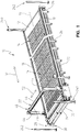
FIG. 1 is a perspective view of an automated gravimetric screening platform system in accordance with an illustrated embodiment of the present disclosure; -
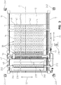
FIG. 2 is a side elevational view, with portions broken away, of the gravimetric screening platform system ofFIG. 1 ; -
FIG. 3 is a top view, with portions broken away, of the gravimetric screening platform system ofFIGs. 1 and2 ; -
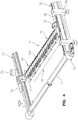
FIG. 4 is a perspective view illustrating a lower gantry including a plurality of load cell modules and a water delivery system for weighing and watering a plurality of pots of the gravimetric screening platform system; -
FIG. 5 is an enlarged perspective view, with portions broken away, of the lower gantry ofFIG. 4 ; -
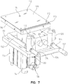
FIGs. 6 and7 are perspective views of one of the load cell modules on the lower gantry; -
FIG. 8 is a sectional view taken through the load cell module ofFIGs. 6 and7 illustrating a pot support surface of the load cell in a retracted position spaced apart from a bottom surface of one of the pots of the gravimetric screening platform system; -
FIG. 9 is a sectional view similar toFIG. 8 , in which the load cell pot support surface is moved to an upwardly extended position to lift the pot for weighing and watering the pot with the load cell module; -
FIGs. 10 and11 are perspective views of one of the pots used with the gravimetric screening platform system; -
FIG. 12 is an exploded perspective view showing a bottom end cap of a fluid reservoir including a check valve to permit water to be supplied from the load cell module to the pot; -
FIG. 13 is a sectional view, with portions broken away, of the pot ofFIGs. 10-12 ; -
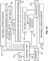
FIG. 14 is a block diagram illustrating additional components of one embodiment of the gravimetric screening platform system; and -
FIG. 15 is a flow chart illustrating steps performed during operation of the gravimetric screening platform system and method. - Corresponding reference characters indicate corresponding parts throughout the several views. Although the drawings represent embodiments of various features and components according to the present disclosure, the drawings are not necessarily to scale and certain features may be exaggerated in order to better illustrate and explain the present disclosure. The exemplification set out herein illustrates embodiments of the invention, and such exemplifications are not to be construed as limiting the scope of the invention in any manner.
- For the purposes of promoting an understanding of the principles of the present disclosure, reference will now be made to the embodiments illustrated in the drawings, which are described below. The embodiments disclosed below are not intended to be exhaustive or limit the invention to the precise form disclosed in the following detailed description. Rather, the embodiments are chosen and described so that others skilled in the art may utilize their teachings. It is understood that no limitation of the scope of the invention is thereby intended. The invention includes any alterations and further modifications in the illustrated devices and described methods and further applications of the principles of the invention which would normally occur to one skilled in the art to which the invention relates.
- Referring initially to
FIGs. 1-3 , an illustrated embodiment of a gravimetricscreening platform system 10 is disclosed. Thesystem 10 includes astationary support platform 12 having a plurality ofopenings 14 formed therein. Theopenings 14 are configured to receive a plurality of specially configured containers orpots 16 therein for growing plants in a controlled environment as discussed herein. Thesystem 10 includes a pair ofupper tracks 18 and a pair oflower tracks 20 located on opposite sides of thesupport platform 12 for supporting upper and lowermovable gantries Upper gantry 22 is best shown inFIGs. 1-3 , whilelower gantry 24 is best shown inFIGs. 4 and5 . Theplatform 12 and tracks 18 and 20 are supported by a plurality ofadjustable support legs 26 which are spaced apart around an outer periphery of theplatform 12. - In an illustrated embodiment, upper and
lower drive mechanisms lower gantries tracks platform 12 as illustrated by double headedarrow 32. In an illustrated embodiment, a chain drive system is used to move the upper andlower gantries tracks drive mechanisms platform 12 are connected byaxles lower gantries - In an illustrated embodiment, the
openings 14 ofplatform 12 are arranged in a plurality ofrows 38 across theplatform 12. As best shown inFIG. 3 , eachrow 38 ofopenings 14 extends in a direction transverse to a longitudinal axis 13 ofplatform 12. In an illustrated embodiment, theplatform 12 includes 44 rows, with 20openings 14 in each row. However, any desired number of rows and openings per row may be used in accordance with the present disclosure. - As shown in
FIG. 3 , each of theopenings 14 includes analignment notch 40 extending away from one side of theopening 14 to align thepot 16 in a proper orientation within theopenings 14 for watering as discussed below.FIG. 3 illustratescertain rows 38 havingpots 16 therein incertain rows 38 without pots located within theopenings 14. - The
upper gantry 22 illustratively includes spaced apart movable supports orshuttle members 42 which ride onupper track members 18 as best shown inFIG. 3 . In an illustrated embodiment, theshuttle members 42 slide back and forth along thetracks 18. Theshuttle members 42 may include rollers, if desired, to facilitate movement of theupper gantry 22 back and forth in the direction of double headedarrow 32.Upper gantry 22 also includes spaced apartvertical supports 44 coupled toshuttle members 42 and ahorizontal support 46 extending over theplatform 12 between the spaced apart vertical supports 44. - A
universal mounting block 48 is coupled to atrack 49 provided on thehorizontal support 46. As best shown inFIG. 3 , adrive mechanism 50, such as a chain drive, is used to move theuniversal mounting block 48 back and forth in the direction of double headedarrow 52 in a direction transverse to the longitudinal axis 13 ofsupport platform 12.Drive mechanism 50 therefore moves theuniversal mounting block 48 back and forth over therows 38 ofpots 16. - In an illustrated embodiment, a
camera 54 and atemperature sensor 56, for example, are coupled to theuniversal mounting block 48 as shown inFIG. 14 .Camera 54 provides still images or video images of the plants growing inpots 16 during an experiment. In one embodiment,camera 54 is a web camera which provides images to a remote location over a communication network. In an illustrated embodiment, thetemperature sensor 56 is an infrared camera to provide thermal imaging of the plants within thepots 16 during the experiment. In one illustrated embodiment, a model A320 infrared camera system available from FLIR Systems is used as thetemperature sensor 56. Other sensors may also be mounted touniversal mounting block 48 to quantify plant stress level and/or canopy characteristics. - As discussed below, a
system controller 100 is used to control the movement ofupper gantry 22 and theuniversal monitoring block 48 during an experiment.Drive mechanism 28 moves theupper gantry 22 back and forth in the direction of double headedarrow 32 to align thehorizontal support 46 of theupper gantry 22 with a desiredrow 38 ofpots 16.Drive mechanism 50 then moves theuniversal mounting block 48 back and forth in the direction of double headedarrow 52 inFIGs. 1 and3 over theparticular row 38 to provide visual and thermal imaging, for example, withcamera 54 andtemperature sensor 56, respectively. - Details of the
lower gantry 24 are best shown inFIGs. 4 and5 .Lower gantry 24 includes first and second moving supports orshuttle members 60 slideably coupled to spaced apartlower tracks 20 as best shown inFIG. 4 . In an illustrated embodiment,shuttle members 60 slide back and forth on thetrack 20.Shuttle members 60 may include rollers, if desired.Drive mechanism 30 moves thelower gantry 24 back and forth in the direction of double headedarrow 32 along the longitudinal axis 13 ofplatform 12.Lower gantry 24 includes a pair ofvertical support members 62 coupled toshuttle members 60 and ahorizontal support 64 extending between thevertical support members 62. - A row of
load cell modules 66 is coupled to thehorizontal support 64 oflower gantry 24. The number ofload cell modules 66 is equal to the number ofopenings 14 within eachrow 38 of thesupport platform 12.Drive mechanism 30 moves thelower gantry 24 so that the row ofload cell modules 66 is aligned directly beneath arow 38 ofpots 16 withinopenings 14 ofplatform 12. As discussed below, theload cell modules 66 are initially spaced apart from bottom surfaces of thepots 16 during movement oflower gantry 24. Once thelower gantry 24 is positioned beneath aparticular row 38 ofpots 16, pot support surfaces 86 of theload cell modules 66 are moved upwardly to engage bottom surfaces ofpots 16 and lift thepots 16. Theload cell modules 66 lift thepots 16 in order to weigh eachpot 16 separately. As further discussed below, water can is then supplied, as needed, through theload cell modules 66 and into bottom openings of thepots 16 to re-water to thepots 16 during an experiment. Therefore, the gravimetricscreening platform system 10 and method of the present disclosure maintains thepots 16 at static locations throughout an experiment without requiring thepots 16 to be moved to a different location for weighing, testing and re-watering. While onerow 38 of pots is lifted at a time in the illustrated embodiments,multiple rows 38 may be lifted simultaneously in other embodiments. - Details of the
load cell modules 66 are illustrated inFIGs. 6-9 . Alower cylinder 70 includes aninternal chamber 72 as best shown inFIGs. 8 and9 . Amovable piston 74 includes aplate 76 located withinchamber 72.Fluid supply lines chamber 70 to selectively supply fluid, such as compressed air or hydraulic fluid, to theinternal chamber 72 ofcylinder 70.Cylinder 70 is coupled tohorizontal support 64 oflower gantry 24.FIG. 8 showspiston 74 in a retracted position in which apot support 86 ofmodule 66 is spaced apart from abottom portion 82 ofpot 16 aslower gantry 24 is moved to align theload cell modules 66 with therow 38 ofpots 16. - In
FIG. 9 , compressed air from anair compressor 214 and supply line ormanifold 215 is supplied throughinlet 78 to move thepiston 74 andplate 76 upwardly in the direction ofarrow 84 to lift theload cell module 66 upwardly. One or more regulators are preferably coupled to themanifold 215. Thepot support 86 therefore also moves upwardly in the direction ofarrow 84 into engagement with thebottom surface 82 ofpot 16 and lifts thepot 16 upwardly so that thepot 16 is supported by thesupport 86.Load cell modules 66 include aload cell 88 having a first end coupled to abase 90 byfasteners 92.Pot support 86 is coupled to an opposite end ofload cell 88 byconnector 94 andfasteners - Once the
pot 16 is lifted and supported bysupport 86, theload cell 88 weighs thepot 16. Acontroller 100 coupled to theload cell 88 byconnectors 89 compares the actual mass of thepot 16 with a desired mass of thepot 16 for a particular experiment protocol.Controller 100 calculates a difference between actual water content within eachpot 16 and the desired water content within thepot 16 based on the predetermined water deficit program of the particular experiment. - If
controller 100 determines that water needs to be added to thepot 16, water can be added directly through theload cell module 66 without moving thepot 16 to another location. As shown inFIGs. 7 and8 ,water supply line 102 is connected to first and secondflow control valves conduits Conduit 130 is coupled betweenvalve 120 andconnector 104.Conduit 132 is coupled betweenvalve 122 andconnector 104.Water supply line 102 is coupled to awater supply 212.Connector 104 best shown inFIGs. 8 and9 is coupled to anopening 106 insupport 86. - In an illustrated embodiment,
flow control valve 120 provides "coarse" fluid flow, whileflow control valve 122 provides "fine" fluid flow. In one illustrated embodiment, fluid flow through courseflow control valve 120 is about ten times greater than the fluid flow throughfine control valve 122, although any desired ratio may be used. In operation,controller 100 initially opens both coarse and fineflow control valves pots 16. As the weight of the pots approaches the desired weight for the particular experiment,controller 100 shuts off the coarseflow control valve 120 and finishes the fill operation using the fineflow control valve 122 to precisely control the amount of water added to thepot 16. - In an illustrated embodiment, a top surface of
support 86 is covered with asilicone pad 108 to improve sealing between thebottom surface 82 ofpot 16 and thepad 108 on top surface ofsupport 86 so that water can be supplied to thepot 16. In an illustrated embodiment, posts 112 extend upwardly from the top surface ofsupport 86 to hold thesilicone pad 108 in place on the top surface ofsupport 86.Pad 108 includes anaperture 114 aligned withaperture 106 ofsupport 86 so that water can flow through thepad 108 and into thepot 16. Although silicone is used forpad 108 in one embodiment, other suitable materials can also be used.Support 86 ofload cell module 66 also includes a groove or notchedportion 110 which is configured to collect water and drain the water away from electrical components of theload cell module 66. - Details of an exemplary embodiment of a
pot 16 are shown inFIGs. 10-13 . Thepot 16 includes abody portion 140 which is generally cylindrically shaped. Thebody portion 140 of thepot 16 is designed to fit within theopenings 14 ofplatform 12 with enough clearance so that when theload cell module 66 lifts thepot 16, thepot 16 is entirely supported by thesupport 86 ofload cell module 66 to permit accurate weighing of thepot 16. Atop end 142 ofpot 16 includes anopening 144 to insert soil and seeds or plants into thepot 16 and permit the plant (not shown) to grow outwardly from thepot 16 in a conventional manner.Top end 142 includes anend cap 146 having anouter flange 148 configured to engage a top surface of thesupport platform 12 when thepot 16 is loaded into anopening 14.Opposite sides 149 offlange 148 are curved to facilitate loading and unloading thepots 16 on theplatform 12. - An
alignment tab 150 is also formed onend cap 146. Thealignment tab 150 is configured to be aligned with anotch 40 ofopenings 14 so that thepot 16 is located in a proper orientation on thesupport platform 12 for weighing and re-watering.Pot 16 includes aninternal water reservoir 152 including abottom portion 153 and a plurality of spaced apart verticalfluid channels 154 for receiving water therein.Bottom end 82 ofpot 16 includes a plurality of ribs 156 and threaded mountingmembers 158 as shown inFIG. 12 . An O-ring 160 is located within anannular groove 162 surrounding thebottom end 82 ofpot 16. Anend cap 164 is coupled tobottom end 82 by fasteners 156 which extend through O-rings 168 andopenings 169 incap 164 and engage threaded mountingmembers 158. - In an illustrated embodiment, a
check valve 170 is coupled to anopening 172 formed inbottom plate 164. Illustratively, adiaphragm 174 andumbrella valve 176 are coupled to theopening 172 by an O-ring seal 178. As best shown inFIGs. 8 and9 , the O-ring seal 178 extends belowbottom surface 82 ofpot 16 to engage thesilicone pad 108 on the top surface ofsupport 86 to provide a seal between theopening 72 and thepad 108 on top surface ofsupport 86. - By placing the
tabs 150 ofpots 16 intonotches 40 ofopenings 14, theopenings 172 intoreservoirs 152 ofpots 16 are automatically aligned withopenings 106 in thesupports 86 ofload cell modules 66 as best shown inFIG. 9 . Therefore, when thepot 16 is lifted as shown ifFIG. 9 , a fluid connection is automatically made betweenaperture 106 insupport 86 andopening 172 ofend cap 164 at thebottom end 82 ofpot 16. Whencontroller 100 causes water to flow by openingvalves connector 104, through theopening 106 ofsupport 86, throughdiaphragm 174 and past thecheck valve 176, and into thereservoir 152 ofpot 16. Fluid flow is illustratively shown byarrow 184 inFIG. 9 . Also as illustrated inFIG. 9 , fluid flows in the direction ofarrows 188 upwardly fromlower portion 153 ofreservoir 152 throughopenings 186 which are in fluid communication with verticalfluid channels 154.Channels 154 includeupper openings 155 located neartop end 142 to drain any water if an overfill condition occurs. As best illustrated inFIGs. 8 ,9 and13 , the internalfluid channels 154 includes an internalsynthetic fabric mesh 190 forming an inner portion of thechannels 154. Themesh 190 permits water to flow through the mesh but prevents soil, debris, or plant roots from accumulating in thevertical channels 154 of thereservoir 152. Aremovable drain plug 194 and o-ring 196 seal adrain opening 198 ofend cap 164.Reservoir 152 is drained by removing thedrain plug 194. - In another illustrated embodiment of the
pot 16, thereservoir 152 is in fluid communication with a tube or channel (not shown) which delivers water from thereservoir 152 to thetop end 142 ofpot 16 for top watering of the plant within the pot. In this embodiment, thepot 16 does not typically include thefluid channels 154 ormesh 190. In yet another embodiment, themesh 190 is replaced with a water impermeable material so that water flows from thereservoir 152 up thechannels 154 in the direction ofarrows 188 to top openings (not shown) adjacenttop end 142 ofpot 16 to provide top watering of the plant within the pot through thechannels 154. - In operation, the
pots 16 are filled with soil, seeds and/or plants as desired for the particular experiment and loaded into theopenings 14 of thesupport platform 12.Tabs 150 ofpots 16 are aligned withnotches 40 ofopenings 14. As best shown inFIG. 3 , aloading platform 200 includesmovable supports 202 coupled toupper track 18.Supports 202 are coupled to ahorizontal support 204 which supportsfolding panels 206. In one embodiment, theloading platform 200 is moved by a drive mechanism back and forth in the direction of double headedarrow 32 along the longitudinal axis 13 ofplatform 12. In another illustrated embodiment, theloading platform 200 is coupled to theupper gantry 22 by connecting arms. Therefore, theupper gantry 22 is used to move theloading platform 200 back and forth onplatform 12 to facilitate loading of thepots 16 into theopenings 14. One embodiment facilitates loading and unloading of thepots 16 at an end of thesupport platform 12. Also in an illustrative embodiment, thefoldable panels 206 permit loading and unloading ofpots 16 at a more ergonomic, lower level than the full height ofsupport platform 12. - A
center portion 208 ofloading platform 200 is opened to expose arow 38 ofopenings 14. Once theloading platform 200 is located over aparticular row 38, theside panels 206 are folded downwardly to overlieadjacent rows 38 ofopenings 14. Therefore, an operator can walk on thepanels 206 to facilitate loading or unloading ofpots 16 fromopenings 14 of the exposedrow 38. After onerow 38 is loaded withpots 16, theloading platform 200 is moved to thenext row 38. Thepanels 208 are illustratively folded upwardly before theloading platform 200 is moved. - Once all the
pots 16 are loaded into thesupport platform 12, an operator selects a particular experiment protocol. The experiment can be selected and monitored using a graphical user input (GUI) 210.GUI 210 is shown as a touch screen inFIGs. 1-3 . However,GUI 210 may include any type of user input. - Operation of the gravimetric
screening platform system 10 and method will now be described in connection withFIGs. 14 and15 . Once thepots 16 have been loaded and the particular experiment protocol has been selected usinggraphical user interface 210,controller 100 automatically controls movement of theupper gantry 22, thelower gantry 24, and theuniversal mounting block 48 relative to thesupport platform 12.Controller 100 also controls the supply of water from awater supply 212 and compressed air fromair compressor 214 to theload cell module 66 coupled to thelower gantry 24. - Referring now to
FIG. 15 , the experiment process starts atblock 220. The upper andlower gantries support platform 12 at the start of the process. Thegantries next row 38 ofopenings 14 andpots 16 as illustrated atblock 222.Controller 100 then controls movement of theuniversal mounting block 48 on thehorizontal support 46 ofupper gantry 22.Controller 100 takes images of the plants withinpots 16 usingcamera 54 and takes temperature readings usinginfrared sensing camera 56 as theuniversal mounting block 48 moves thecameras particular row 38 as illustrated atblock 224. In an illustrated embodiment, thecamera 54 andtemperature sensor 56 are located within a heat protected enclosure so that thecameras cameras memory 101 bycontroller 100. - Once the
lower gantry 24 is moved into position underneath theparticular row 38,controller 100 controls the supply of compressed air fromair supply 214 tocylinders 70 to raise each of the plurality ofload cell modules 66 from the retracted position ofFIG. 8 to the extended position ofFIG. 9 to lift eachpot 16 in therow 38 upwardly as illustrated atblock 226. As discussed above, thepots 16 are entirely supported by thesupports 86 ofload cell modules 66 in the extended positions. -
Controller 100 then weighs each pot as illustrated atblock 228 and stores the weight information for eachpot 16 inmemory 101. Next,controller 100 determines whether it is necessary to add water to any of thepots 16 as illustrated atblock 230. If no water needs to be added,controller 100 advances to block 234 ofFIG. 15 . If water needs to be added atblock 230,controller 100controls valves water supply 212 through theload cell modules 66 and into thepots 16 as discussed in detail above. Water is added until the weight of the pots reaches the desired weight for the particular experiment as illustrated atblock 232. The new pot weights taken after re-watering are stored inmemory 101. Next,controller 100 controls theair supply 214 to move thepistons 74 ofload cell module 66 from the extended position ofFIG. 9 back to the retracted position ofFIG. 8 as illustrated atblock 234. In this position, thepots 16 are again supported byflanges 148 which engage thesupport platform 12. -
Controller 100 then determines whether theparticular row 38 is thelast row 38 on thesupport platform 12 as illustrated atblock 236. If so,controller 100 moves the upper andlower gantries block 238. If the row was not the last row atblock 236,controller 100 moves the upper andlower gantries next row 38 atblock 222 and then proceeds with the remaining steps ofFIG. 15 for thenext row 38. - During the re-watering process, nutrients can be added to the soil, if desired. In addition, water can be used to flush nutrients out of the
pots 16 by overfilling the reservoirs and allowing water to escape throughoverflow openings 155. Nitrogen use efficiency (NUE) experiments may be conducted. - As best shown in
FIGs. 1-3 ,outer sensors system 10. If thedetectors controller 100 shuts off operation of thesystem 10. Once the area is clear,controller 100 starts the process again at the same step in the procedure. - While embodiments of the present disclosure have been described as having exemplary designs, the present invention may be further modified within the scope of the appended claims. This application is therefore intended to cover any variations, uses, or adaptations of the disclosure using its general principles. Further, this application is intended to cover such departures from the present disclosure as come within known or customary practice in the art to which this invention pertains, as defined in the appended claims.
Claims (30)
- A system (10) for controlling soil moisture in a plurality of potted plants to perform water deficit experiments, the system comprising:a stationary platform (12) having a plurality of openings (14) formed therein, the openings being located in a plurality of rows (38) on the platform;a plurality of pots (16) located in the plurality of openings in the platform, the pots being supported by the platform;a movable lower gantry (24) located below the platform, the movable lower gantry supporting a plurality of load cell modules (66) aligned with the plurality of pots located in a row of openings, each load cell module including a load cell (88) having a support (86) movable from a retracted position spaced apart from a bottom surface (82) of a pot to an extended position in which the support of the load cell lifts the pot upwardly to support the weight of the pot thereon, the load cell weighing the lifted pot;a controller (100) coupled to the load cell, the controller being programmed to determine whether the pots need watering based on the weights of the pots and the water deficit experiment; anda water supply (212) coupled to the load cell modules, the water supply including at least one flow control valve (120, 122) controlled by the controller to selectively supply water, characterized in that water is supplied to the pots through the load cell modules.
- The system of claim 1, further comprising an upper gantry (22) movable above the platform (12), the upper gantry including at least one sensor (56) located thereon to acquire data related to the plants in the plurality of pots (16).
- The system of claim 2, wherein the at least one sensor (56) on the upper gantry (22) includes a camera (54) to take images of the plants in the plurality of pots (16).
- The system of claim 2, wherein the at least sensor (56) on the upper gantry (22) includes a temperature sensor.
- The system of claim 4, wherein the temperature sensor (56) is an infrared camera.
- The system of claim 2, wherein the upper gantry (22) includes a drive mechanism (28) which moves the at least one sensor (56) back and forth on the upper gantry over the rows (38) of pots (16) located within the openings (14) of the platform (12).
- The system of claim 2, wherein the upper gantry (22) includes first and second spaced apart shuttle members (42) coupled to spaced apart upper tracks (18) located on opposite sides of the platform (12) to permit movement of the upper gantry over the platform, first and second spaced vertical supports (44) coupled to the first and second shuttle members, respectively, and a horizontal support (46) extending over the platform (12) between the first and second spaced vertical supports of the upper gantry, the at least one sensor (56) being coupled to the horizontal support of the upper gantry.
- The system of claim 1, wherein the lower gantry (24) includes first and second spaced apart shuttle members (60) coupled to spaced apart lower tracks (20) located on opposite sides of the platform (12) to permit movement of the lower gantry under the platform, first and second spaced vertical supports (62) coupled to the first and second shuttle members, respectively, and a horizontal support (64) extending under the platform between the first and second spaced vertical supports of the lower gantry, the plurality of load cell modules (66) being coupled to the horizontal support of the lower gantry.
- The system of claim 8, wherein the horizontal support (64) of the lower gantry supports a fluid supply line (78, 80) coupled to the load cell modules (66) for selectively extending and retracting the supports (86) of the load cell modules, and a water supply line (102) coupled to the load cell modules to supply water to the pots (16) through the load cell modules.
- The system of claim 9, wherein the supports (86) of the load cell modules (66) include an opening (106) in fluid communication with the water supply line (102), and wherein each of the plurality of pots (16) includes a fluid reservoir (152) having a fill opening (172) located on a bottom surface (82) of the pot and a check valve (170) coupled to the fill opening to permit water supplied through the opening of the support of the load cell module to enter the fill opening of the pot through the check valve.
- The system of claim 10, wherein the fluid reservoir (152) of each pot (16) includes a bottom portion (153) in communication with the fill opening (172) and a plurality of vertically extending fluid channels (154) to supply water to the soil within the pot.
- The system of claim 11, further comprising a mesh (190) forming an inner portion of the vertically extending fluid channels (154), the mesh permitting water to flow through the mesh to the soil, but preventing soil debris and plant roots from accumulating in the vertically extending fluid channels of the reservoir (152).
- The system of claim 11, further comprising an overfill opening in communication with each of the fluid channels, the overfill openings being located near a top end of the pot (16).
- The system of claim 10, wherein the fill openings (172) of the pots are offset from a center axis of the pots (16), and wherein each pot includes an alignment tab (150) configured to be located within a notched portion (40) of the opening (14) formed in the platform (12) to align the fill opening (172) of the pot with the water supply (106) opening in the support (86) of the load cell module.
- The system of claim 10, further comprising a pad (108) located on the support (86) of each load cell module (66), the pad improving a seal between the fill opening (172) of the pot and the water supply opening (106) formed in the support (86) of the load cell module (66).
- The system of claim 15, wherein the pad (108) includes an opening (114) aligned with the water supply opening (106) in the support (86) of the load cell module (66).
- The system of claim 16, wherein the support (86) of the load cell module (66) includes a plurality of posts (112) configured to align the pad (108) on the support (86).
- The system of claim 1, wherein the support (86) of the load cell module (66) includes a notched portion (110) configured to drain fluid off the support.
- The system of claim 1, wherein each load cell module (66) includes a cylinder (70) and a piston (74) located in the cylinder, the piston being coupled to the load cell (88) and movable between a retracted position and an extended position to move the load cell and the support (86) from the retracted position spaced apart from the bottom surface (82) of a pot (16) to the extended position in which the support of the load cell lifts the pot upwardly to support the weight of the pot thereon.
- The system of claim 1, wherein each pot (16) includes a cylindrically shaped body portion (140) and a flange (148) located at top end of the pot, the flange being configured to engage the platform (12) when the body portion of the pot is inserted into the opening (14) in the platform to support the pot on the platform.
- The system of claim 1, further comprising a loading platform (200) movable relative to the stationary platform (12), the loading platform including at least one foldable panel (206) configured to overlie a plurality of rows (38) of openings (14) of the platform (12) to facilitate loading of pots (16) into the openings located adjacent the foldable panel.
- The system of claim 1, wherein the water supply (212) is coupled to the load cell module (66) by first (120) and second (122) flow control valves, the first flow control valve having a fluid flow rate greater than the second flow control valve, and wherein the controller (100) initially opens both the first and second flow control valves to begin filling the pots (16), the controller closing the first flow control valve as the weight of the pots approaches a desired weight for the water deficit experiment and finishes the filling the pot with the second flow control valve to precisely control the amount of water added to the pot.
- A method for controlling soil moisture in a plurality of potted plants to perform water deficit experiments, the method comprising:providing a stationary platform (12) having a plurality of openings (14) therein;locating a plurality of pots (16) in the openings of the platform, the pots being supported by the platform;lifting the pots with a plurality of load cell modules (66);weighing each of the plurality of pots with the load cell modules;determining whether the pots need to be watered based on the weight of the pots and the water deficit experiment;watering the pots through the load cell modules, if necessary, based on the determining step; andlowering the plurality of load cell modules so that the plurality of pots are supported by the platform.
- The method of claim 23, wherein the openings (14) in the platform (12) are located in a plurality of rows (38), the step of moving a plurality of load cell modules (66) under the platform aligns the load cell modules with a row of pots (16), and the step of lifting the pots lifts an entire row of pots with the plurality of load cell modules simultaneously.
- The method of claim 24, further comprising moving the load cell modules (66) to a next row (38) of pots (16) and performing the lifting , weighing , determining, watering, and lowering steps for the next row of pots.
- The method of claim 23, further comprising moving at least one sensor (56) over the rows (38) of pots (16) to collect data related to the plants.
- A pot (16) for use with a system (10) for controlling soil moisture in a plurality of potted plants to perform water deficit experiments, the system including a stationary platform (12) having a plurality of openings (14) formed therein, the pot comprising:a body portion (140) having an open top end (142) and a bottom end (82);a flange (148) coupled to the body portion adjacent the top end, the flange being configured to be able to engage the platform to hold the body portion within an opening of the platform;a fluid reservoir (152) having a bottom portion (153) located adjacent the bottom end of the body portion, a plurality of vertically extending fluid (154) channels extending upwardly toward the top end of the body portion, wherein the bottom portion (153) of the fluid reservoir (152) is circumscribed by an end cap (164) coupled to the bottom end of the body portion, the fluid reservoir having further a fill opening (172) formed in the end cap (164) in fluid communication with the bottom portion (153) of the fluid reservoir (152); anda check valve (170) coupled to the fill opening (172) to permit fluid to be supplied to the fluid reservoir (152) from the end cap through the fill opening (172) and the check valve (170).
- The pot (16) of claim 27, further comprising a mesh (190) forming an inner portion of the vertically extending fluid channels (154), the mesh permitting fluid to flow through the mesh to soil within the body portion (140), but preventing soil debris and plant roots from accumulating in the vertically extending fluid channels of the reservoir (152).
- The pot (16) of claim 27, further comprising an overfill opening (155) in communication with each of the fluid channels (154), the overfill openings being located near the top end of the body portion (140).
- The pot (16) of claim 27, wherein the fill opening (172) is offset from a center axis of the body portion, and further comprising an alignment tab (150) located near the top end of the body portion (140), the alignment tab being configured to be located within a notched portion (40) of the opening (14) formed in the platform (12) to align the fill opening (172) with a water supply (212).
Applications Claiming Priority (2)
| Application Number | Priority Date | Filing Date | Title |
|---|---|---|---|
| US201161476055P | 2011-04-15 | 2011-04-15 | |
| PCT/US2012/033054 WO2012148676A1 (en) | 2011-04-15 | 2012-04-11 | Automated gravimetric screening platform system and method |
Publications (2)
| Publication Number | Publication Date |
|---|---|
| EP2696670A1 EP2696670A1 (en) | 2014-02-19 |
| EP2696670B1 true EP2696670B1 (en) | 2018-05-23 |
Family
ID=45976544
Family Applications (1)
| Application Number | Title | Priority Date | Filing Date |
|---|---|---|---|
| EP12715283.3A Not-in-force EP2696670B1 (en) | 2011-04-15 | 2012-04-11 | Automated gravimetric screening platform system and method |
Country Status (14)
| Country | Link |
|---|---|
| US (3) | US8955252B2 (en) |
| EP (1) | EP2696670B1 (en) |
| CN (2) | CN103747668B (en) |
| AR (1) | AR086077A1 (en) |
| AU (1) | AU2012250114B2 (en) |
| BR (1) | BR102012008743A2 (en) |
| CA (1) | CA2832878A1 (en) |
| MX (1) | MX339210B (en) |
| NZ (1) | NZ713640A (en) |
| RU (1) | RU2593906C2 (en) |
| TW (1) | TW201249330A (en) |
| UA (1) | UA113171C2 (en) |
| UY (1) | UY34021A (en) |
| WO (1) | WO2012148676A1 (en) |
Cited By (2)
| Publication number | Priority date | Publication date | Assignee | Title |
|---|---|---|---|---|
| WO2020260304A1 (en) | 2019-06-24 | 2020-12-30 | KWS SAAT SE & Co. KGaA | System and method for phenotyping of organisms |
| EP4277460A4 (en) * | 2021-01-15 | 2024-11-20 | Maui Greens, Inc. | Grow module for plant vessels |
Families Citing this family (26)
| Publication number | Priority date | Publication date | Assignee | Title |
|---|---|---|---|---|
| CA2851129C (en) * | 2011-10-30 | 2017-10-31 | Paskal Technologies Agriculture Cooperative Society Ltd. | Self-learning of plant growth strategy in a greenhouse |
| TW201325435A (en) * | 2011-12-22 | 2013-07-01 | Univ Nat Taiwan | Working stage structure and monitoring system for planting bed |
| US9451745B1 (en) * | 2012-09-21 | 2016-09-27 | The United States Of America, As Represented By The Secretary Of Agriculture | Multi-band photodiode sensor |
| TWI503074B (en) * | 2013-08-16 | 2015-10-11 | Univ Nat Taiwan | Plant growth weight measurement instrument and method thereof |
| CN103493700B (en) * | 2013-09-22 | 2015-10-28 | 同济大学 | A kind of moving nursery bed Precision Irrigation integral system |
| US9149006B1 (en) * | 2015-02-18 | 2015-10-06 | Albert J. Pope | Garden made EZ modular planter device |
| CN104663373B (en) * | 2015-03-20 | 2017-08-18 | 山东农业大学 | An automatic irrigation and water monitoring device for crop pot experiments |
| US9516820B1 (en) * | 2015-11-23 | 2016-12-13 | Control Dekk | Irrigation system for hanging plants and method of irrigating hanging plants |
| CA3022138C (en) | 2016-05-19 | 2020-11-24 | Vermeer Manufacturing Company | Self-propelled baling vehicle |
| CN106171868A (en) * | 2016-07-11 | 2016-12-07 | 北京禾木源农业科技有限责任公司 | A kind of domestic tidal irrigation device |
| DE102017203245A1 (en) * | 2017-02-28 | 2018-08-30 | Phenospex B.V. | Device for monitoring plants |
| US10524433B2 (en) | 2017-05-08 | 2020-01-07 | Daniel S. Spiro | Automated vertical plant cultivation system |
| US11129339B2 (en) * | 2017-05-08 | 2021-09-28 | Daniel S. Spiro | Automated vertical plant cultivation system |
| US11122748B2 (en) | 2017-05-08 | 2021-09-21 | Daniel S. Spiro | Automated outdoor modular vertical plant cultivation system |
| US11617309B2 (en) | 2017-05-08 | 2023-04-04 | Urban Planter, Llc | Automated vertical plant cultivation system |
| US11622510B2 (en) | 2017-05-08 | 2023-04-11 | Urban Planter, Llc | Automated vertical plant cultivation system |
| JOP20190140A1 (en) * | 2017-06-14 | 2019-06-11 | Grow Solutions Tech Llc | System and method for using water as a stabilizer in an assembly line growth chamber |
| JOP20190153A1 (en) * | 2017-06-14 | 2019-06-20 | Grow Solutions Tech Llc | Systems and methods for managing a weight of a plant in a grow pod |
| CN107371861B (en) * | 2017-07-18 | 2020-11-06 | 安徽阜阳金丰生态农业有限公司 | Stabilizer for vine crop planting |
| US11778955B2 (en) | 2017-11-29 | 2023-10-10 | Urban Planter, Llc | Automated vertical plant cultivation system |
| NL2022188B1 (en) * | 2018-12-12 | 2020-07-02 | Van Egmond Lisianthus Holding B V | A method for growing seedlings during seed germination and/or seedling growth. |
| KR20210081902A (en) * | 2019-12-24 | 2021-07-02 | 엘지전자 주식회사 | Plant cultivating apparatus |
| CN111011067B (en) * | 2020-01-03 | 2021-10-26 | 广东省农业科学院果树研究所 | Automatic sprinkling irrigation system for agricultural greenhouse |
| CN117177660A (en) * | 2021-01-15 | 2023-12-05 | 毛伊格林斯股份有限公司 | System for plant container fertilization |
| CN114794030B (en) * | 2022-06-16 | 2022-10-14 | 广东省农业科学院植物保护研究所 | A kind of citrus psyllid drug resistance monitoring device and drug resistance determination method |
| CN120603487A (en) * | 2022-08-02 | 2025-09-05 | 苏帕咨询私人有限公司 | A plant watering system |
Family Cites Families (28)
| Publication number | Priority date | Publication date | Assignee | Title |
|---|---|---|---|---|
| US2486512A (en) * | 1945-06-08 | 1949-11-01 | Nelson B Armstrong | Method and apparatus for promoting the growth of vegetation |
| US2755745A (en) * | 1951-05-28 | 1956-07-24 | Harold L Lewis | Self watering container |
| US3293799A (en) * | 1964-02-04 | 1966-12-27 | Exxon Research Engineering Co | Automatic irrigation of pot cultures in plant growth rooms and greenhouses |
| USRE27234E (en) * | 1970-04-02 | 1971-11-09 | Hydraulic lifting device with weight estimator | |
| SU952167A1 (en) * | 1978-09-22 | 1982-08-23 | Институт Физиологии Растений Ан Усср | Apparatus for watering plants |
| DD285919A5 (en) * | 1989-07-25 | 1991-01-10 | Forschzent Bodenfruchtbarkeit | AUTOMATIC VEGETATION TABLE |
| US5020275A (en) * | 1990-10-15 | 1991-06-04 | Bednarzik Uwe H | Watering method and apparatus for plants |
| US5241786A (en) * | 1991-03-29 | 1993-09-07 | The Walt Disney Company | Irrigation control system |
| US5220745A (en) | 1991-11-25 | 1993-06-22 | Irrigation Technologies, Inc. | Drip irrigation apparatus for pots and planters |
| US5351437A (en) | 1992-05-12 | 1994-10-04 | Lishman Fred W | Moisture sensitive irrigation control system |
| US5611172A (en) * | 1992-10-06 | 1997-03-18 | Agripak, Inc. | Apparatus for the treatment of live plants |
| US5761848A (en) * | 1993-09-15 | 1998-06-09 | Manlove; Steve | Nursery container |
| US5852896A (en) * | 1997-11-10 | 1998-12-29 | Flasch, Jr.; Robert J. | Container and method of growing a plant |
| US6314340B1 (en) * | 1998-11-02 | 2001-11-06 | Telsco Industries | Irrigation controller |
| US6124554A (en) * | 1999-06-01 | 2000-09-26 | Muckle; Thomas A. | Portable pallet scale |
| US6901699B2 (en) * | 2002-06-20 | 2005-06-07 | Gary Raymond Hartman | Seed-starter cell and tray for starting plants |
| US6691460B1 (en) * | 2002-09-13 | 2004-02-17 | San Fu Lee | Self-watering and fertilizing pot for plants |
| US6962022B2 (en) | 2002-10-04 | 2005-11-08 | Shannon Sandy S | Suspended barrier for a plant pot |
| US20040177553A1 (en) | 2003-03-14 | 2004-09-16 | Harbaugh Kenneth A. | Plant container with selectively sealable drainage hole |
| US20050086861A1 (en) * | 2003-10-22 | 2005-04-28 | Atchley Frederic P. | Adaptable plant root development container |
| US6843021B1 (en) | 2004-03-09 | 2005-01-18 | Shih-Ming Huang | Floatable plant cultivation device |
| US7809475B2 (en) * | 2004-12-20 | 2010-10-05 | Fw Enviro, Llc | Computer controlled fertigation system and method |
| GB0601391D0 (en) * | 2006-01-24 | 2006-03-01 | Mckenna Malachi C | Sump Action Plant Waterer |
| US20090260285A1 (en) * | 2008-04-18 | 2009-10-22 | Smith Thomas J | Self-orientating plant pot and tray system |
| US20100031568A1 (en) * | 2008-08-11 | 2010-02-11 | Lee Burnett, DO, APC | Container watering system and method |
| JP5537349B2 (en) | 2010-02-11 | 2014-07-02 | Kddi株式会社 | Method and system for changing SIP server while terminal connection is continued |
| US8584397B1 (en) * | 2010-06-25 | 2013-11-19 | James Marsh | Automated plant watering system |
| AR091288A1 (en) | 2010-09-27 | 2015-01-28 | Inst De Agrobiotecnologia De Rosario Indear | AUTOMATIC PHENOTIPATE PLATFORM |
-
2012
- 2012-04-11 CN CN201280029134.5A patent/CN103747668B/en not_active Expired - Fee Related
- 2012-04-11 CN CN201610546515.0A patent/CN106234171A/en active Pending
- 2012-04-11 CA CA2832878A patent/CA2832878A1/en not_active Abandoned
- 2012-04-11 WO PCT/US2012/033054 patent/WO2012148676A1/en not_active Ceased
- 2012-04-11 AU AU2012250114A patent/AU2012250114B2/en not_active Ceased
- 2012-04-11 EP EP12715283.3A patent/EP2696670B1/en not_active Not-in-force
- 2012-04-11 RU RU2013150820/13A patent/RU2593906C2/en not_active IP Right Cessation
- 2012-04-11 NZ NZ713640A patent/NZ713640A/en not_active IP Right Cessation
- 2012-04-11 US US13/444,095 patent/US8955252B2/en active Active
- 2012-04-11 MX MX2013012049A patent/MX339210B/en active IP Right Grant
- 2012-04-12 AR ARP120101263A patent/AR086077A1/en unknown
- 2012-04-12 TW TW101112995A patent/TW201249330A/en unknown
- 2012-04-13 BR BR102012008743-0A patent/BR102012008743A2/en not_active Application Discontinuation
- 2012-04-13 UY UY0001034021A patent/UY34021A/en not_active Application Discontinuation
- 2012-11-04 UA UAA201313265A patent/UA113171C2/en unknown
-
2014
- 2014-11-13 US US14/540,706 patent/US9681611B2/en active Active
- 2014-11-13 US US14/540,695 patent/US9675012B2/en active Active
Non-Patent Citations (1)
| Title |
|---|
| DAUZAT MYRIAM ET AL: "AUTOMATE DE PHENOTYPAGE POUR CULTIVER DES PLANTES A DES ETATS HYDRIQUES DU SOL CONTROLES", 1 January 2004 (2004-01-01), pages 21 - 33, XP055422175, Retrieved from the Internet <URL:https://www6.inra.fr/cahier_des_techniques/content/download/4351/42397/version/1/file/CT53_ART5_Auzat_Phenotypage.pdf> [retrieved on 20171107] * |
Cited By (3)
| Publication number | Priority date | Publication date | Assignee | Title |
|---|---|---|---|---|
| WO2020260304A1 (en) | 2019-06-24 | 2020-12-30 | KWS SAAT SE & Co. KGaA | System and method for phenotyping of organisms |
| EP4277460A4 (en) * | 2021-01-15 | 2024-11-20 | Maui Greens, Inc. | Grow module for plant vessels |
| EP4277462A4 (en) * | 2021-01-15 | 2025-02-12 | Maui Greens, Inc. | System for fertigation of plant vessels |
Also Published As
| Publication number | Publication date |
|---|---|
| BR102012008743A2 (en) | 2014-05-13 |
| MX2013012049A (en) | 2013-12-16 |
| WO2012148676A1 (en) | 2012-11-01 |
| US20120260569A1 (en) | 2012-10-18 |
| CN103747668A (en) | 2014-04-23 |
| AU2012250114A1 (en) | 2013-02-21 |
| RU2593906C2 (en) | 2016-08-10 |
| RU2013150820A (en) | 2015-05-20 |
| US8955252B2 (en) | 2015-02-17 |
| AU2012250114B2 (en) | 2014-11-06 |
| US20150068120A1 (en) | 2015-03-12 |
| AR086077A1 (en) | 2013-11-20 |
| US9681611B2 (en) | 2017-06-20 |
| UY34021A (en) | 2012-11-30 |
| UA113171C2 (en) | 2016-12-26 |
| US9675012B2 (en) | 2017-06-13 |
| CA2832878A1 (en) | 2012-11-01 |
| CN106234171A (en) | 2016-12-21 |
| MX339210B (en) | 2016-05-12 |
| US20150068119A1 (en) | 2015-03-12 |
| NZ713640A (en) | 2017-02-24 |
| CN103747668B (en) | 2016-08-17 |
| TW201249330A (en) | 2012-12-16 |
| EP2696670A1 (en) | 2014-02-19 |
| NZ615992A (en) | 2015-11-27 |
Similar Documents
| Publication | Publication Date | Title |
|---|---|---|
| US8955252B2 (en) | Automated gravimetric screening platform system and method | |
| US9027279B2 (en) | Plant cultivation device and feed-water control method | |
| KR101903018B1 (en) | Automatic High Position Cultivating System Based on Human Machine Interface | |
| CN113433019A (en) | Vegetation slope protection erosion penetration experiment simulation device and simulation method | |
| CN106035036A (en) | Water culturing device suitable for whole-growing-period testing of soybean | |
| KR101224110B1 (en) | Apparauts for growing strawberry seedlings | |
| AU2014262298B2 (en) | Automated gravimetric screening platform system and method | |
| CN117491591A (en) | A device and method for dynamic monitoring of the evapotranspiration process of a multifunctional composite planting system | |
| JP7337405B2 (en) | Cultivation system for growing plants | |
| CN112577877A (en) | Water and fertilizer integrated drip irrigation control migration testing device and method for black soil and multiple soil layers in cold region | |
| NZ615992B2 (en) | Automated gravimetric screening platform system and method | |
| HK1193004B (en) | Automated gravimetric screening platform system and method | |
| KR102835876B1 (en) | Measurement system for carbon dioxide elimination efficiency of moss using residual gas analyzer | |
| HK1193004A (en) | Automated gravimetric screening platform system and method | |
| KR20220061736A (en) | Green-house control system by hanging-bed weight measurement | |
| JP2017200459A (en) | Elevated culture method and elevated culture apparatus | |
| CN121128489B (en) | Melon device of growing seedlings based on intelligent regulation and control | |
| NL2022188B1 (en) | A method for growing seedlings during seed germination and/or seedling growth. | |
| CN120827064A (en) | A device and method for pre-cultivating shrub-herb combinations for ecological restoration of power transmission and transformation projects | |
| RU2641193C1 (en) | Lysimeter | |
| CN121795187A (en) | An apparatus and method for detecting the drought resistance of wheat seeds | |
| CN121128489A (en) | A melon seedling raising device based on intelligent control | |
| CN117330510A (en) | A device and method for obtaining the three-dimensional structure of wheat roots based on transparent soil | |
| AU2002244515B8 (en) | Means and method of generating feed | |
| AU2002244515A1 (en) | Means and method of generating feed |
Legal Events
| Date | Code | Title | Description |
|---|---|---|---|
| PUAI | Public reference made under article 153(3) epc to a published international application that has entered the european phase |
Free format text: ORIGINAL CODE: 0009012 |
|
| 17P | Request for examination filed |
Effective date: 20131025 |
|
| AK | Designated contracting states |
Kind code of ref document: A1 Designated state(s): AL AT BE BG CH CY CZ DE DK EE ES FI FR GB GR HR HU IE IS IT LI LT LU LV MC MK MT NL NO PL PT RO RS SE SI SK SM TR |
|
| DAX | Request for extension of the european patent (deleted) | ||
| REG | Reference to a national code |
Ref country code: DE Ref legal event code: R079 Ref document number: 602012046586 Country of ref document: DE Free format text: PREVIOUS MAIN CLASS: A01G0007000000 Ipc: A01G0009240000 |
|
| GRAP | Despatch of communication of intention to grant a patent |
Free format text: ORIGINAL CODE: EPIDOSNIGR1 |
|
| STAA | Information on the status of an ep patent application or granted ep patent |
Free format text: STATUS: GRANT OF PATENT IS INTENDED |
|
| RIC1 | Information provided on ipc code assigned before grant |
Ipc: A01G 9/08 20060101ALI20171107BHEP Ipc: A01G 9/24 20060101AFI20171107BHEP Ipc: A01G 27/02 20060101ALI20171107BHEP |
|
| INTG | Intention to grant announced |
Effective date: 20171127 |
|
| GRAS | Grant fee paid |
Free format text: ORIGINAL CODE: EPIDOSNIGR3 |
|
| GRAA | (expected) grant |
Free format text: ORIGINAL CODE: 0009210 |
|
| STAA | Information on the status of an ep patent application or granted ep patent |
Free format text: STATUS: THE PATENT HAS BEEN GRANTED |
|
| RIN1 | Information on inventor provided before grant (corrected) |
Inventor name: DONALDSON, JEFFREY D. Inventor name: HERVE, PHILIPPE Inventor name: KELLER, DOUGLAS Inventor name: GOLGOTIU, KIRSTI A. Inventor name: SWARTWOOD, TROY M. |
|
| AK | Designated contracting states |
Kind code of ref document: B1 Designated state(s): AL AT BE BG CH CY CZ DE DK EE ES FI FR GB GR HR HU IE IS IT LI LT LU LV MC MK MT NL NO PL PT RO RS SE SI SK SM TR |
|
| REG | Reference to a national code |
Ref country code: GB Ref legal event code: FG4D |
|
| REG | Reference to a national code |
Ref country code: CH Ref legal event code: EP |
|
| REG | Reference to a national code |
Ref country code: IE Ref legal event code: FG4D |
|
| REG | Reference to a national code |
Ref country code: DE Ref legal event code: R096 Ref document number: 602012046586 Country of ref document: DE |
|
| REG | Reference to a national code |
Ref country code: AT Ref legal event code: REF Ref document number: 1000738 Country of ref document: AT Kind code of ref document: T Effective date: 20180615 |
|
| REG | Reference to a national code |
Ref country code: NL Ref legal event code: MP Effective date: 20180523 |
|
| REG | Reference to a national code |
Ref country code: LT Ref legal event code: MG4D |
|
| PG25 | Lapsed in a contracting state [announced via postgrant information from national office to epo] |
Ref country code: ES Free format text: LAPSE BECAUSE OF FAILURE TO SUBMIT A TRANSLATION OF THE DESCRIPTION OR TO PAY THE FEE WITHIN THE PRESCRIBED TIME-LIMIT Effective date: 20180523 Ref country code: LT Free format text: LAPSE BECAUSE OF FAILURE TO SUBMIT A TRANSLATION OF THE DESCRIPTION OR TO PAY THE FEE WITHIN THE PRESCRIBED TIME-LIMIT Effective date: 20180523 Ref country code: NO Free format text: LAPSE BECAUSE OF FAILURE TO SUBMIT A TRANSLATION OF THE DESCRIPTION OR TO PAY THE FEE WITHIN THE PRESCRIBED TIME-LIMIT Effective date: 20180823 Ref country code: SE Free format text: LAPSE BECAUSE OF FAILURE TO SUBMIT A TRANSLATION OF THE DESCRIPTION OR TO PAY THE FEE WITHIN THE PRESCRIBED TIME-LIMIT Effective date: 20180523 Ref country code: FI Free format text: LAPSE BECAUSE OF FAILURE TO SUBMIT A TRANSLATION OF THE DESCRIPTION OR TO PAY THE FEE WITHIN THE PRESCRIBED TIME-LIMIT Effective date: 20180523 Ref country code: BG Free format text: LAPSE BECAUSE OF FAILURE TO SUBMIT A TRANSLATION OF THE DESCRIPTION OR TO PAY THE FEE WITHIN THE PRESCRIBED TIME-LIMIT Effective date: 20180823 |
|
| PG25 | Lapsed in a contracting state [announced via postgrant information from national office to epo] |
Ref country code: GR Free format text: LAPSE BECAUSE OF FAILURE TO SUBMIT A TRANSLATION OF THE DESCRIPTION OR TO PAY THE FEE WITHIN THE PRESCRIBED TIME-LIMIT Effective date: 20180824 Ref country code: RS Free format text: LAPSE BECAUSE OF FAILURE TO SUBMIT A TRANSLATION OF THE DESCRIPTION OR TO PAY THE FEE WITHIN THE PRESCRIBED TIME-LIMIT Effective date: 20180523 Ref country code: LV Free format text: LAPSE BECAUSE OF FAILURE TO SUBMIT A TRANSLATION OF THE DESCRIPTION OR TO PAY THE FEE WITHIN THE PRESCRIBED TIME-LIMIT Effective date: 20180523 Ref country code: NL Free format text: LAPSE BECAUSE OF FAILURE TO SUBMIT A TRANSLATION OF THE DESCRIPTION OR TO PAY THE FEE WITHIN THE PRESCRIBED TIME-LIMIT Effective date: 20180523 Ref country code: HR Free format text: LAPSE BECAUSE OF FAILURE TO SUBMIT A TRANSLATION OF THE DESCRIPTION OR TO PAY THE FEE WITHIN THE PRESCRIBED TIME-LIMIT Effective date: 20180523 |
|
| REG | Reference to a national code |
Ref country code: AT Ref legal event code: MK05 Ref document number: 1000738 Country of ref document: AT Kind code of ref document: T Effective date: 20180523 |
|
| PG25 | Lapsed in a contracting state [announced via postgrant information from national office to epo] |
Ref country code: SK Free format text: LAPSE BECAUSE OF FAILURE TO SUBMIT A TRANSLATION OF THE DESCRIPTION OR TO PAY THE FEE WITHIN THE PRESCRIBED TIME-LIMIT Effective date: 20180523 Ref country code: AT Free format text: LAPSE BECAUSE OF FAILURE TO SUBMIT A TRANSLATION OF THE DESCRIPTION OR TO PAY THE FEE WITHIN THE PRESCRIBED TIME-LIMIT Effective date: 20180523 Ref country code: DK Free format text: LAPSE BECAUSE OF FAILURE TO SUBMIT A TRANSLATION OF THE DESCRIPTION OR TO PAY THE FEE WITHIN THE PRESCRIBED TIME-LIMIT Effective date: 20180523 Ref country code: PL Free format text: LAPSE BECAUSE OF FAILURE TO SUBMIT A TRANSLATION OF THE DESCRIPTION OR TO PAY THE FEE WITHIN THE PRESCRIBED TIME-LIMIT Effective date: 20180523 Ref country code: CZ Free format text: LAPSE BECAUSE OF FAILURE TO SUBMIT A TRANSLATION OF THE DESCRIPTION OR TO PAY THE FEE WITHIN THE PRESCRIBED TIME-LIMIT Effective date: 20180523 Ref country code: RO Free format text: LAPSE BECAUSE OF FAILURE TO SUBMIT A TRANSLATION OF THE DESCRIPTION OR TO PAY THE FEE WITHIN THE PRESCRIBED TIME-LIMIT Effective date: 20180523 |
|
| REG | Reference to a national code |
Ref country code: DE Ref legal event code: R097 Ref document number: 602012046586 Country of ref document: DE |
|
| PG25 | Lapsed in a contracting state [announced via postgrant information from national office to epo] |
Ref country code: IT Free format text: LAPSE BECAUSE OF FAILURE TO SUBMIT A TRANSLATION OF THE DESCRIPTION OR TO PAY THE FEE WITHIN THE PRESCRIBED TIME-LIMIT Effective date: 20180523 Ref country code: SM Free format text: LAPSE BECAUSE OF FAILURE TO SUBMIT A TRANSLATION OF THE DESCRIPTION OR TO PAY THE FEE WITHIN THE PRESCRIBED TIME-LIMIT Effective date: 20180523 |
|
| PLBE | No opposition filed within time limit |
Free format text: ORIGINAL CODE: 0009261 |
|
| STAA | Information on the status of an ep patent application or granted ep patent |
Free format text: STATUS: NO OPPOSITION FILED WITHIN TIME LIMIT |
|
| 26N | No opposition filed |
Effective date: 20190226 |
|
| PG25 | Lapsed in a contracting state [announced via postgrant information from national office to epo] |
Ref country code: SI Free format text: LAPSE BECAUSE OF FAILURE TO SUBMIT A TRANSLATION OF THE DESCRIPTION OR TO PAY THE FEE WITHIN THE PRESCRIBED TIME-LIMIT Effective date: 20180523 |
|
| REG | Reference to a national code |
Ref country code: DE Ref legal event code: R119 Ref document number: 602012046586 Country of ref document: DE |
|
| PG25 | Lapsed in a contracting state [announced via postgrant information from national office to epo] |
Ref country code: AL Free format text: LAPSE BECAUSE OF FAILURE TO SUBMIT A TRANSLATION OF THE DESCRIPTION OR TO PAY THE FEE WITHIN THE PRESCRIBED TIME-LIMIT Effective date: 20180523 |
|
| REG | Reference to a national code |
Ref country code: CH Ref legal event code: PL |
|
| REG | Reference to a national code |
Ref country code: BE Ref legal event code: MM Effective date: 20190430 |
|
| GBPC | Gb: european patent ceased through non-payment of renewal fee |
Effective date: 20190411 |
|
| PG25 | Lapsed in a contracting state [announced via postgrant information from national office to epo] |
Ref country code: MC Free format text: LAPSE BECAUSE OF FAILURE TO SUBMIT A TRANSLATION OF THE DESCRIPTION OR TO PAY THE FEE WITHIN THE PRESCRIBED TIME-LIMIT Effective date: 20180523 Ref country code: LU Free format text: LAPSE BECAUSE OF NON-PAYMENT OF DUE FEES Effective date: 20190411 |
|
| PG25 | Lapsed in a contracting state [announced via postgrant information from national office to epo] |
Ref country code: LI Free format text: LAPSE BECAUSE OF NON-PAYMENT OF DUE FEES Effective date: 20190430 Ref country code: DE Free format text: LAPSE BECAUSE OF NON-PAYMENT OF DUE FEES Effective date: 20191101 Ref country code: CH Free format text: LAPSE BECAUSE OF NON-PAYMENT OF DUE FEES Effective date: 20190430 Ref country code: GB Free format text: LAPSE BECAUSE OF NON-PAYMENT OF DUE FEES Effective date: 20190411 |
|
| PG25 | Lapsed in a contracting state [announced via postgrant information from national office to epo] |
Ref country code: BE Free format text: LAPSE BECAUSE OF NON-PAYMENT OF DUE FEES Effective date: 20190430 |
|
| PG25 | Lapsed in a contracting state [announced via postgrant information from national office to epo] |
Ref country code: TR Free format text: LAPSE BECAUSE OF FAILURE TO SUBMIT A TRANSLATION OF THE DESCRIPTION OR TO PAY THE FEE WITHIN THE PRESCRIBED TIME-LIMIT Effective date: 20180523 |
|
| PG25 | Lapsed in a contracting state [announced via postgrant information from national office to epo] |
Ref country code: IE Free format text: LAPSE BECAUSE OF NON-PAYMENT OF DUE FEES Effective date: 20190411 |
|
| PG25 | Lapsed in a contracting state [announced via postgrant information from national office to epo] |
Ref country code: PT Free format text: LAPSE BECAUSE OF FAILURE TO SUBMIT A TRANSLATION OF THE DESCRIPTION OR TO PAY THE FEE WITHIN THE PRESCRIBED TIME-LIMIT Effective date: 20180924 Ref country code: FR Free format text: LAPSE BECAUSE OF NON-PAYMENT OF DUE FEES Effective date: 20190430 |
|
| PG25 | Lapsed in a contracting state [announced via postgrant information from national office to epo] |
Ref country code: CY Free format text: LAPSE BECAUSE OF FAILURE TO SUBMIT A TRANSLATION OF THE DESCRIPTION OR TO PAY THE FEE WITHIN THE PRESCRIBED TIME-LIMIT Effective date: 20180523 |
|
| PG25 | Lapsed in a contracting state [announced via postgrant information from national office to epo] |
Ref country code: IS Free format text: LAPSE BECAUSE OF FAILURE TO SUBMIT A TRANSLATION OF THE DESCRIPTION OR TO PAY THE FEE WITHIN THE PRESCRIBED TIME-LIMIT Effective date: 20180923 Ref country code: EE Free format text: LAPSE BECAUSE OF NON-PAYMENT OF DUE FEES Effective date: 20180523 |
|
| PG25 | Lapsed in a contracting state [announced via postgrant information from national office to epo] |
Ref country code: MT Free format text: LAPSE BECAUSE OF FAILURE TO SUBMIT A TRANSLATION OF THE DESCRIPTION OR TO PAY THE FEE WITHIN THE PRESCRIBED TIME-LIMIT Effective date: 20180523 Ref country code: HU Free format text: LAPSE BECAUSE OF FAILURE TO SUBMIT A TRANSLATION OF THE DESCRIPTION OR TO PAY THE FEE WITHIN THE PRESCRIBED TIME-LIMIT; INVALID AB INITIO Effective date: 20120411 |
|
| PG25 | Lapsed in a contracting state [announced via postgrant information from national office to epo] |
Ref country code: MK Free format text: LAPSE BECAUSE OF FAILURE TO SUBMIT A TRANSLATION OF THE DESCRIPTION OR TO PAY THE FEE WITHIN THE PRESCRIBED TIME-LIMIT Effective date: 20180523 |