EP2696574A2 - Wärmebildkamera mit intermittierender Bilderfassung - Google Patents
Wärmebildkamera mit intermittierender Bilderfassung Download PDFInfo
- Publication number
- EP2696574A2 EP2696574A2 EP13179943.9A EP13179943A EP2696574A2 EP 2696574 A2 EP2696574 A2 EP 2696574A2 EP 13179943 A EP13179943 A EP 13179943A EP 2696574 A2 EP2696574 A2 EP 2696574A2
- Authority
- EP
- European Patent Office
- Prior art keywords
- scene
- infrared
- camera
- capturing
- thermal imaging
- Prior art date
- Legal status (The legal status is an assumption and is not a legal conclusion. Google has not performed a legal analysis and makes no representation as to the accuracy of the status listed.)
- Granted
Links
Images



Classifications
-
- H—ELECTRICITY
- H04—ELECTRIC COMMUNICATION TECHNIQUE
- H04N—PICTORIAL COMMUNICATION, e.g. TELEVISION
- H04N23/00—Cameras or camera modules comprising electronic image sensors; Control thereof
- H04N23/20—Cameras or camera modules comprising electronic image sensors; Control thereof for generating image signals from infrared radiation only
- H04N23/23—Cameras or camera modules comprising electronic image sensors; Control thereof for generating image signals from infrared radiation only from thermal infrared radiation
Definitions
- Thermal imaging cameras are used in a variety of situations. For example, thermal imaging cameras are often used during maintenance inspections to thermally inspect equipment.
- Example equipment may include rotating machinery, electrical panels, or rows of circuit breakers, among other types of equipment.
- Thermal inspections can detect equipment hot spots such as overheating machinery or electrical components, helping to ensure timely repair or replacement of the overheating equipment before a more significant problem develops.
- the thermal imaging camera may also generate a visible light image of the same object.
- the camera may display the infrared image and the visible light image in a coordinated manner, for example, to help an operator interpret the thermal image generated by the thermal imaging camera.
- visible light images which generally provide good contrast between different objects, it is often difficult to recognize and distinguish different features in a thermal image as compared to the real-world scene. For this reason, an operator may rely on a visible light image to help interpret and focus the thermal image.
- this disclosure is directed to a thermal imaging camera that intermittently captures infrared images for long term monitoring of a scene.
- Certain embodiments of the invention include a method of monitoring a temperature of a scene using a thermal imaging camera, including selecting a temperature threshold on the camera, capturing an infrared image of the scene, detecting a thermal energy of the scene and capturing infrared images of the scene when the thermal energy of the scene changes by the threshold amount.
- mpeg encoder blocks of a system on chip may be used to detect threshold changes in the thermal energy of the scene.
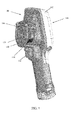
- FIG. 1 is a perspective front view of a thermal imaging camera according to some embodiments.
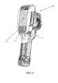
- FIG. 2 is a perspective back view of the thermal imaging camera of FIG. 1 .
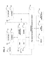
- FIG. 3 is a functional block diagram illustrating components of thermal imaging cameras according to some embodiments.
- FIG. 4 is a conceptual illustration of an example of a picture-in-picture type concurrent display of a visual image and an infrared image.
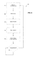
- FIG 7 is a flow chart of another process for capturing intermittent infrared images according to some embodiments.
- a thermal imaging camera may be used to detect heat patterns across a scene, including an object or objects, under observation.
- the thermal imaging camera may detect infrared radiation given off by the scene and convert the infrared radiation into an infrared image indicative of the heat patterns.
- the thermal imaging camera may also capture visible light from the scene and convert the visible light into a visible light image.
- the camera may include infrared optics to focus the infrared radiation on an infrared sensor and visible light optics to focus the visible light on a visible light sensor.
- FIGS. 1 and 2 show front and back perspective views, respectively of an example thermal imaging camera 100, which includes a housing 102, an infrared lens assembly 104, a visible light lens assembly 106, a display 108, a laser 110, and a trigger control 112.
- Housing 102 houses the various components of thermal imaging camera 100.
- the bottom portion of thermal imaging camera 100 includes a carrying handle for holding and operating the camera via one hand.
- Infrared lens assembly 104 receives infrared radiation from a scene and focuses the radiation on an infrared sensor for generating an infrared image of a scene.
- Visible light lens assembly 106 receives visible light from a scene and focuses the visible light on a visible light sensor for generating a visible light image of the same scene.
- thermal imaging camera 100 collects or captures the infrared energy and visible light energy substantially simultaneously (e.g., at the same time) so that the visible light image and the infrared image generated by the camera are of the same scene at substantially the same time.
- the infrared image generated by thermal imaging camera 100 is indicative of localized temperatures within the scene at a particular period of time while the visible light image generated by the camera is indicative of the same scene at the same period of time.
- thermal imaging camera may capture infrared energy and visible light energy from a scene at different periods of time.
- Visible light lens assembly 106 includes at least one lens that focuses visible light energy on a visible light sensor for generating a visible light image. Visible light lens assembly 106 defines a visible light optical axis which passes through the center of curvature of the at least one lens of the assembly. Visible light energy projects through a front of the lens and focuses on an opposite side of the lens. Visible light lens assembly 106 can include a single lens or a plurality of lenses (e.g., two, three, or more lenses) arranged in series. In addition, visible light lens assembly 106 can have a fixed focus or can include a focus adjustment mechanism for changing the focus of the visible light optics. In examples in which visible light lens assembly 106 includes a focus adjustment mechanism, the focus adjustment mechanism may be a manual adjustment mechanism or an automatic adjustment mechanism.
- thermal imaging camera 100 includes a focus mechanism for adjusting the focus of an infrared image captured by the camera.
- thermal imaging camera 100 includes focus ring 114.
- Focus ring 114 is operatively coupled (e.g., mechanically and/or electrically coupled) to at least one lens of infrared lens assembly 104 and configured to move the at least one lens to various focus positions so as to focus the infrared image captured by thermal imaging camera 100.
- Focus ring 114 may be manually rotated about at least a portion of housing 102 so as to move the at least one lens to which the focus ring is operatively coupled.
- focus ring 114 is also operatively coupled to display 108 such that rotation of focus ring 114 causes at least a portion of a visible light image and at least a portion of an infrared image concurrently displayed on display 108 to move relative to one another.
- thermal imaging camera 100 may include a manual focus adjustment mechanism that is implemented in a configuration other than focus ring 114.
- Data of the distance-to-target, as measured by the laser 110, can be stored and associated with the corresponding captured image. For images which are captured using automatic focus, this data will be gathered as part of the focusing process.
- the thermal imaging camera will also detect and save the distance-to-target data when an image is captured. This data may be obtained by the thermal imaging camera when the image is captured by using the laser 110 or, alternatively, by detecting the lens position and correlating the lens position to a known distance-to-target associated with that lens position.
- Infrared camera module 200 may be configured to receive infrared energy emitted by a target scene and to focus the infrared energy on an infrared sensor for generation of infrared energy data, e.g., that can be displayed in the form of an infrared image on display 108 and/or stored in memory.
- Infrared camera module 200 can include any suitable components for performing the functions attributed to the module herein.
- infrared camera module 200 is illustrated as including infrared lens assembly 104 and infrared sensor 220. As described above with respect to FIGS.
- Infrared lens assembly 104 can have a variety of different configurations.
- infrared lens assembly 104 defines a F-number (which may also be referred to as a focal ratio or F-stop) of a specific magnitude.
- a F-number may be determined by dividing the focal length of a lens (e.g., an outermost lens of infrared lens assembly 104) by a diameter of an entrance to the lens, which may be indicative of the amount of infrared radiation entering the lens.
- increasing the F-number of infrared lens assembly 104 may increase the depth-of-field, or distance between nearest and farthest objects in a target scene that are in acceptable focus, of the lens assembly.
- Infrared sensor 220 may include one or more focal plane arrays (FPA) that generate electrical signals in response to infrared energy received through infrared lens assembly 104.
- FPA focal plane arrays
- Each FPA can include a plurality of infrared sensor elements including, e.g., bolometers, photon detectors, or other suitable infrared sensor elements.
- each sensor element which may each be referred to as a sensor pixel, may change an electrical characteristic (e.g., voltage or resistance) in response to absorbing infrared energy received from a target scene.
- the change in electrical characteristic can provide an electrical signal that can be received by a processor 222 and processed into an infrared image displayed on display 108.
- the FPA array can define any suitable size and shape.
- infrared sensor 220 includes a plurality of infrared sensor elements arranged in a grid pattern such as, e.g., an array of sensor elements arranged in vertical columns and horizontal rows.
- infrared sensor 220 may include an array of vertical columns by horizontal rows of, e.g., 16 x 16, 50 x 50, 160 x 120, 120 x 160, or 650 x 480.
- infrared sensor 220 may include a smaller number of vertical columns and horizontal rows (e.g., 1 x 1), a larger number vertical columns and horizontal rows (e.g., 1000 x 1000), or a different ratio of columns to rows.
- a Read Out Integrated Circuit is incorporated on the IR sensor 220.
- the ROIC is used to output signals corresponding to each of the pixels.
- Such ROIC is commonly fabricated as an integrated circuit on a silicon substrate.
- the plurality of detector elements may be fabricated on top of the ROIC, wherein their combination provides for the IR sensor 220.
- the ROIC can include components discussed elsewhere in this disclosure (e.g. an analog-to-digital converter (ADC)) incorporated directly onto the FPA circuitry.
- ADC analog-to-digital converter
- Various embodiments may include optionally putting the thermal imaging camera into a sleep mode in which the supply of power is discontinued to some but not all of the components of the thermal imaging camera and certain data in memory are maintained.
- the power may be discontinued to all components of the camera except the delay timer, and power may be re-supplied to the entire thermal imaging camera upon expiration of the delay timer interval.
- the sleep mode may include temporarily discontinuing power to the display 108 and portions of or all of the processor 222.
Landscapes
- Health & Medical Sciences (AREA)
- Toxicology (AREA)
- Engineering & Computer Science (AREA)
- Multimedia (AREA)
- Signal Processing (AREA)
- Studio Devices (AREA)
- Radiation Pyrometers (AREA)
- Closed-Circuit Television Systems (AREA)
Applications Claiming Priority (1)
| Application Number | Priority Date | Filing Date | Title |
|---|---|---|---|
| US13/572,078 US8907282B2 (en) | 2012-08-10 | 2012-08-10 | Thermal imaging camera with intermittent image capture |
Publications (3)
| Publication Number | Publication Date |
|---|---|
| EP2696574A2 true EP2696574A2 (de) | 2014-02-12 |
| EP2696574A3 EP2696574A3 (de) | 2014-04-02 |
| EP2696574B1 EP2696574B1 (de) | 2019-04-03 |
Family
ID=48979587
Family Applications (1)
| Application Number | Title | Priority Date | Filing Date |
|---|---|---|---|
| EP13179943.9A Active EP2696574B1 (de) | 2012-08-10 | 2013-08-09 | Wärmebildkamera mit intermittierender Bilderfassung |
Country Status (3)
| Country | Link |
|---|---|
| US (1) | US8907282B2 (de) |
| EP (1) | EP2696574B1 (de) |
| CN (1) | CN103575406B (de) |
Families Citing this family (32)
| Publication number | Priority date | Publication date | Assignee | Title |
|---|---|---|---|---|
| KR101982075B1 (ko) * | 2012-09-28 | 2019-05-24 | 엘지이노텍 주식회사 | Tv 장치 |
| US9251615B2 (en) * | 2013-03-15 | 2016-02-02 | Fluke Corporation | Thermal image animation |
| USD763261S1 (en) * | 2013-04-30 | 2016-08-09 | Symbol Technologies, Llc | Ergonomic mobile computing device |
| US10493298B2 (en) * | 2013-08-02 | 2019-12-03 | Varian Medical Systems, Inc. | Camera systems and methods for use in one or more areas in a medical facility |
| CN104135601A (zh) * | 2014-07-18 | 2014-11-05 | 北京计算机技术及应用研究所 | 一种用户可定制相机及其通用相机系统 |
| CN104135627B (zh) * | 2014-08-06 | 2018-03-30 | 努比亚技术有限公司 | 物体运动轨迹拍摄方法和系统 |
| US10602082B2 (en) | 2014-09-17 | 2020-03-24 | Fluke Corporation | Triggered operation and/or recording of test and measurement or imaging tools |
| WO2016061754A1 (zh) * | 2014-10-22 | 2016-04-28 | 中国科学院自动化研究所 | 一种手持式分子影像导航系统 |
| EP3210055B1 (de) * | 2014-10-24 | 2023-02-22 | Fluke Electronics Corporation | Tragbares infrarot-bildgebungsgerät zur erkennung unterliegender strukturen |
| WO2016065262A1 (en) * | 2014-10-24 | 2016-04-28 | Fluke Corporation | Underlying wall structure finder and infrared camera |
| WO2016065261A1 (en) | 2014-10-24 | 2016-04-28 | Fluke Corporation | Imaging system employing fixed, modular mobile, and portable infrared cameras with ability to receive, communicate, and display data and images with proximity detection |
| USD781860S1 (en) | 2015-07-21 | 2017-03-21 | Symbol Technologies, Llc | Mobile computer device |
| USD807374S1 (en) | 2015-07-21 | 2018-01-09 | Symbol Technologies, Llc | Bezel component for a mobile computer device |
| US20170078544A1 (en) | 2015-09-16 | 2017-03-16 | Fluke Corporation | Electrical isolation for a camera in a test and measurement tool |
| WO2017070629A1 (en) | 2015-10-23 | 2017-04-27 | Fluke Corporation | Imaging tool for vibration and/or misalignment analysis |
| EP3381021B1 (de) * | 2015-11-23 | 2021-01-06 | Essence Security International (E.S.I.) Ltd. | Thermischer bewegungsdetektor und wärmebildkamera |
| GB2544970B (en) * | 2015-11-27 | 2018-01-24 | Sony Interactive Entertainment Inc | Image capture apparatus |
| WO2017171962A2 (en) * | 2016-01-11 | 2017-10-05 | Carrier Corporation | Infrared presence detector system |
| US11428577B2 (en) * | 2016-02-17 | 2022-08-30 | Carrier Corporation | Pyroelectric presence identification system |
| JP6387045B2 (ja) | 2016-05-26 | 2018-09-05 | キヤノン株式会社 | 放射線撮像装置およびその制御方法 |
| US10506193B2 (en) * | 2016-07-19 | 2019-12-10 | Snap-On Incorporated | Methods and systems for displaying a thermal image and information related to servicing a vehicle |
| CN106533479A (zh) * | 2016-10-20 | 2017-03-22 | 上海宜君科技有限公司 | 红外成像搜索方法及具有红外成像搜索功能的对讲机 |
| US10768682B2 (en) * | 2017-01-20 | 2020-09-08 | Flir Systems, Inc. | Detection-based wakeup of detection devices |
| TWI633496B (zh) * | 2017-10-05 | 2018-08-21 | 中國鋼鐵股份有限公司 | 用以辨識物體移動方向的方法 |
| US11070763B2 (en) * | 2018-06-27 | 2021-07-20 | Snap-On Incorporated | Method and system for displaying images captured by a computing device including a visible light camera and a thermal camera |
| USD918210S1 (en) | 2019-04-04 | 2021-05-04 | Zebra Technologies Corporation | Data capture device |
| CN110864809B (zh) * | 2019-06-28 | 2021-07-09 | 武钢集团昆明钢铁股份有限公司 | 罐体的监测方法 |
| US11363909B2 (en) * | 2020-04-15 | 2022-06-21 | Air Products And Chemicals, Inc. | Sensor device for providing control for a food processing system |
| LU101928B1 (en) | 2020-07-17 | 2022-01-17 | Microsoft Technology Licensing Llc | Modifying operation of sensors using collected sensor data |
| CN114205518A (zh) * | 2020-10-30 | 2022-03-18 | 杭州美盛红外光电技术有限公司 | 任务监测系统、检测装置和监测方法 |
| US20220417453A1 (en) * | 2021-06-29 | 2022-12-29 | Brad Ritti | System for a thermal monitoring security camera |
| US11867559B2 (en) | 2022-04-25 | 2024-01-09 | Snap-On Incorporated | Thermal imager devices |
Family Cites Families (11)
| Publication number | Priority date | Publication date | Assignee | Title |
|---|---|---|---|---|
| US6215898B1 (en) * | 1997-04-15 | 2001-04-10 | Interval Research Corporation | Data processing system and method |
| US10973397B2 (en) * | 1999-03-01 | 2021-04-13 | West View Research, Llc | Computerized information collection and processing apparatus |
| JP2004309719A (ja) * | 2003-04-04 | 2004-11-04 | Olympus Corp | 顕微鏡システム、顕微鏡システムの制御方法、及び制御プログラム |
| US7471334B1 (en) | 2004-11-22 | 2008-12-30 | Stenger Thomas A | Wildlife-sensing digital camera with instant-on capability and picture management software |
| EP2034348A4 (de) | 2006-05-15 | 2011-04-20 | Nikon Corp | Zeitraffer-fotografiereinrichtung |
| US7693679B1 (en) | 2007-02-08 | 2010-04-06 | Fluke Corporation | System and method for configuring a thermal imaging instrument |
| JP2010008856A (ja) | 2008-06-30 | 2010-01-14 | Olympus Corp | 顕微鏡撮像装置及び顕微鏡撮像システム |
| CN201919108U (zh) * | 2010-10-28 | 2011-08-03 | 刘佳茜 | 一种监控系统 |
| WO2012115881A1 (en) * | 2011-02-22 | 2012-08-30 | Flir Systems, Inc. | Infrared sensor systems and methods |
| CN202018340U (zh) * | 2011-03-21 | 2011-10-26 | 中国航天科工集团第三研究院第八三五八研究所 | 一种电子稳像装置 |
| CN102231797A (zh) * | 2011-06-22 | 2011-11-02 | 深圳中兴力维技术有限公司 | 日夜摄像装置、用于日夜摄像装置的日夜切换方法 |
-
2012
- 2012-08-10 US US13/572,078 patent/US8907282B2/en active Active
-
2013
- 2013-08-08 CN CN201310342755.5A patent/CN103575406B/zh active Active
- 2013-08-09 EP EP13179943.9A patent/EP2696574B1/de active Active
Non-Patent Citations (1)
| Title |
|---|
| None |
Also Published As
| Publication number | Publication date |
|---|---|
| US20140042319A1 (en) | 2014-02-13 |
| CN103575406A (zh) | 2014-02-12 |
| EP2696574B1 (de) | 2019-04-03 |
| US8907282B2 (en) | 2014-12-09 |
| CN103575406B (zh) | 2016-10-05 |
| EP2696574A3 (de) | 2014-04-02 |
Similar Documents
| Publication | Publication Date | Title |
|---|---|---|
| US8907282B2 (en) | Thermal imaging camera with intermittent image capture | |
| US9413988B2 (en) | Thermal imaging camera with graphical temperature plot | |
| EP2741491B1 (de) | Kamera und Verfahren zur thermischen Bildrauschverringerung unter Verwendung von Nachverarbeitungstechniken | |
| US20140267757A1 (en) | Parallax correction in thermal imaging cameras | |
| US10366496B2 (en) | Visible light image with edge marking for enhancing IR imagery | |
| US11022546B2 (en) | Optical gas imaging systems and methods | |
| US20140184805A1 (en) | Thermal camera and method for eliminating ghosting effects of hot-target thermal images | |
| US20130155249A1 (en) | Thermal imaging camera for infrared rephotography | |
| US20130155248A1 (en) | Thermal imaging camera for infrared rephotography | |
| US10965889B2 (en) | Thermal imager that analyzes temperature measurement calculation accuracy | |
| US9635283B2 (en) | Thermal imager with large dynamic range and improved signal-to-noise ratio | |
| WO2012177740A2 (en) | Thermal imager that analyzes temperature measurement calculation accuracy | |
| CN108476295B (zh) | 从多个图像生成图像的方法、热成像相机以及介质 |
Legal Events
| Date | Code | Title | Description |
|---|---|---|---|
| AK | Designated contracting states |
Kind code of ref document: A2 Designated state(s): AL AT BE BG CH CY CZ DE DK EE ES FI FR GB GR HR HU IE IS IT LI LT LU LV MC MK MT NL NO PL PT RO RS SE SI SK SM TR |
|
| AX | Request for extension of the european patent |
Extension state: BA ME |
|
| PUAI | Public reference made under article 153(3) epc to a published international application that has entered the european phase |
Free format text: ORIGINAL CODE: 0009012 |
|
| PUAL | Search report despatched |
Free format text: ORIGINAL CODE: 0009013 |
|
| AK | Designated contracting states |
Kind code of ref document: A3 Designated state(s): AL AT BE BG CH CY CZ DE DK EE ES FI FR GB GR HR HU IE IS IT LI LT LU LV MC MK MT NL NO PL PT RO RS SE SI SK SM TR |
|
| AX | Request for extension of the european patent |
Extension state: BA ME |
|
| RIC1 | Information provided on ipc code assigned before grant |
Ipc: H04N 5/33 20060101AFI20140221BHEP |
|
| 17P | Request for examination filed |
Effective date: 20141001 |
|
| RBV | Designated contracting states (corrected) |
Designated state(s): AL AT BE BG CH CY CZ DE DK EE ES FI FR GB GR HR HU IE IS IT LI LT LU LV MC MK MT NL NO PL PT RO RS SE SI SK SM TR |
|
| STAA | Information on the status of an ep patent application or granted ep patent |
Free format text: STATUS: EXAMINATION IS IN PROGRESS |
|
| 17Q | First examination report despatched |
Effective date: 20170116 |
|
| RAP1 | Party data changed (applicant data changed or rights of an application transferred) |
Owner name: FLUKE CORPORATION |
|
| GRAP | Despatch of communication of intention to grant a patent |
Free format text: ORIGINAL CODE: EPIDOSNIGR1 |
|
| STAA | Information on the status of an ep patent application or granted ep patent |
Free format text: STATUS: GRANT OF PATENT IS INTENDED |
|
| INTG | Intention to grant announced |
Effective date: 20181207 |
|
| GRAS | Grant fee paid |
Free format text: ORIGINAL CODE: EPIDOSNIGR3 |
|
| GRAA | (expected) grant |
Free format text: ORIGINAL CODE: 0009210 |
|
| STAA | Information on the status of an ep patent application or granted ep patent |
Free format text: STATUS: THE PATENT HAS BEEN GRANTED |
|
| AK | Designated contracting states |
Kind code of ref document: B1 Designated state(s): AL AT BE BG CH CY CZ DE DK EE ES FI FR GB GR HR HU IE IS IT LI LT LU LV MC MK MT NL NO PL PT RO RS SE SI SK SM TR |
|
| REG | Reference to a national code |
Ref country code: GB Ref legal event code: FG4D |
|
| REG | Reference to a national code |
Ref country code: CH Ref legal event code: EP Ref country code: AT Ref legal event code: REF Ref document number: 1117221 Country of ref document: AT Kind code of ref document: T Effective date: 20190415 |
|
| REG | Reference to a national code |
Ref country code: DE Ref legal event code: R096 Ref document number: 602013053203 Country of ref document: DE |
|
| REG | Reference to a national code |
Ref country code: IE Ref legal event code: FG4D |
|
| REG | Reference to a national code |
Ref country code: NL Ref legal event code: MP Effective date: 20190403 |
|
| REG | Reference to a national code |
Ref country code: LT Ref legal event code: MG4D |
|
| REG | Reference to a national code |
Ref country code: AT Ref legal event code: MK05 Ref document number: 1117221 Country of ref document: AT Kind code of ref document: T Effective date: 20190403 |
|
| PG25 | Lapsed in a contracting state [announced via postgrant information from national office to epo] |
Ref country code: NL Free format text: LAPSE BECAUSE OF FAILURE TO SUBMIT A TRANSLATION OF THE DESCRIPTION OR TO PAY THE FEE WITHIN THE PRESCRIBED TIME-LIMIT Effective date: 20190403 |
|
| PG25 | Lapsed in a contracting state [announced via postgrant information from national office to epo] |
Ref country code: FI Free format text: LAPSE BECAUSE OF FAILURE TO SUBMIT A TRANSLATION OF THE DESCRIPTION OR TO PAY THE FEE WITHIN THE PRESCRIBED TIME-LIMIT Effective date: 20190403 Ref country code: CZ Free format text: LAPSE BECAUSE OF FAILURE TO SUBMIT A TRANSLATION OF THE DESCRIPTION OR TO PAY THE FEE WITHIN THE PRESCRIBED TIME-LIMIT Effective date: 20190403 Ref country code: NO Free format text: LAPSE BECAUSE OF FAILURE TO SUBMIT A TRANSLATION OF THE DESCRIPTION OR TO PAY THE FEE WITHIN THE PRESCRIBED TIME-LIMIT Effective date: 20190703 Ref country code: HR Free format text: LAPSE BECAUSE OF FAILURE TO SUBMIT A TRANSLATION OF THE DESCRIPTION OR TO PAY THE FEE WITHIN THE PRESCRIBED TIME-LIMIT Effective date: 20190403 Ref country code: LT Free format text: LAPSE BECAUSE OF FAILURE TO SUBMIT A TRANSLATION OF THE DESCRIPTION OR TO PAY THE FEE WITHIN THE PRESCRIBED TIME-LIMIT Effective date: 20190403 Ref country code: ES Free format text: LAPSE BECAUSE OF FAILURE TO SUBMIT A TRANSLATION OF THE DESCRIPTION OR TO PAY THE FEE WITHIN THE PRESCRIBED TIME-LIMIT Effective date: 20190403 Ref country code: SE Free format text: LAPSE BECAUSE OF FAILURE TO SUBMIT A TRANSLATION OF THE DESCRIPTION OR TO PAY THE FEE WITHIN THE PRESCRIBED TIME-LIMIT Effective date: 20190403 Ref country code: PT Free format text: LAPSE BECAUSE OF FAILURE TO SUBMIT A TRANSLATION OF THE DESCRIPTION OR TO PAY THE FEE WITHIN THE PRESCRIBED TIME-LIMIT Effective date: 20190803 Ref country code: AL Free format text: LAPSE BECAUSE OF FAILURE TO SUBMIT A TRANSLATION OF THE DESCRIPTION OR TO PAY THE FEE WITHIN THE PRESCRIBED TIME-LIMIT Effective date: 20190403 |
|
| PG25 | Lapsed in a contracting state [announced via postgrant information from national office to epo] |
Ref country code: LV Free format text: LAPSE BECAUSE OF FAILURE TO SUBMIT A TRANSLATION OF THE DESCRIPTION OR TO PAY THE FEE WITHIN THE PRESCRIBED TIME-LIMIT Effective date: 20190403 Ref country code: BG Free format text: LAPSE BECAUSE OF FAILURE TO SUBMIT A TRANSLATION OF THE DESCRIPTION OR TO PAY THE FEE WITHIN THE PRESCRIBED TIME-LIMIT Effective date: 20190703 Ref country code: RS Free format text: LAPSE BECAUSE OF FAILURE TO SUBMIT A TRANSLATION OF THE DESCRIPTION OR TO PAY THE FEE WITHIN THE PRESCRIBED TIME-LIMIT Effective date: 20190403 Ref country code: GR Free format text: LAPSE BECAUSE OF FAILURE TO SUBMIT A TRANSLATION OF THE DESCRIPTION OR TO PAY THE FEE WITHIN THE PRESCRIBED TIME-LIMIT Effective date: 20190704 Ref country code: PL Free format text: LAPSE BECAUSE OF FAILURE TO SUBMIT A TRANSLATION OF THE DESCRIPTION OR TO PAY THE FEE WITHIN THE PRESCRIBED TIME-LIMIT Effective date: 20190403 |
|
| PG25 | Lapsed in a contracting state [announced via postgrant information from national office to epo] |
Ref country code: IS Free format text: LAPSE BECAUSE OF FAILURE TO SUBMIT A TRANSLATION OF THE DESCRIPTION OR TO PAY THE FEE WITHIN THE PRESCRIBED TIME-LIMIT Effective date: 20190803 Ref country code: AT Free format text: LAPSE BECAUSE OF FAILURE TO SUBMIT A TRANSLATION OF THE DESCRIPTION OR TO PAY THE FEE WITHIN THE PRESCRIBED TIME-LIMIT Effective date: 20190403 |
|
| REG | Reference to a national code |
Ref country code: DE Ref legal event code: R097 Ref document number: 602013053203 Country of ref document: DE |
|
| PG25 | Lapsed in a contracting state [announced via postgrant information from national office to epo] |
Ref country code: RO Free format text: LAPSE BECAUSE OF FAILURE TO SUBMIT A TRANSLATION OF THE DESCRIPTION OR TO PAY THE FEE WITHIN THE PRESCRIBED TIME-LIMIT Effective date: 20190403 Ref country code: SK Free format text: LAPSE BECAUSE OF FAILURE TO SUBMIT A TRANSLATION OF THE DESCRIPTION OR TO PAY THE FEE WITHIN THE PRESCRIBED TIME-LIMIT Effective date: 20190403 Ref country code: DK Free format text: LAPSE BECAUSE OF FAILURE TO SUBMIT A TRANSLATION OF THE DESCRIPTION OR TO PAY THE FEE WITHIN THE PRESCRIBED TIME-LIMIT Effective date: 20190403 Ref country code: EE Free format text: LAPSE BECAUSE OF FAILURE TO SUBMIT A TRANSLATION OF THE DESCRIPTION OR TO PAY THE FEE WITHIN THE PRESCRIBED TIME-LIMIT Effective date: 20190403 |
|
| PLBE | No opposition filed within time limit |
Free format text: ORIGINAL CODE: 0009261 |
|
| STAA | Information on the status of an ep patent application or granted ep patent |
Free format text: STATUS: NO OPPOSITION FILED WITHIN TIME LIMIT |
|
| PG25 | Lapsed in a contracting state [announced via postgrant information from national office to epo] |
Ref country code: SM Free format text: LAPSE BECAUSE OF FAILURE TO SUBMIT A TRANSLATION OF THE DESCRIPTION OR TO PAY THE FEE WITHIN THE PRESCRIBED TIME-LIMIT Effective date: 20190403 Ref country code: IT Free format text: LAPSE BECAUSE OF FAILURE TO SUBMIT A TRANSLATION OF THE DESCRIPTION OR TO PAY THE FEE WITHIN THE PRESCRIBED TIME-LIMIT Effective date: 20190403 |
|
| 26N | No opposition filed |
Effective date: 20200106 |
|
| PG25 | Lapsed in a contracting state [announced via postgrant information from national office to epo] |
Ref country code: TR Free format text: LAPSE BECAUSE OF FAILURE TO SUBMIT A TRANSLATION OF THE DESCRIPTION OR TO PAY THE FEE WITHIN THE PRESCRIBED TIME-LIMIT Effective date: 20190403 |
|
| PG25 | Lapsed in a contracting state [announced via postgrant information from national office to epo] |
Ref country code: SI Free format text: LAPSE BECAUSE OF FAILURE TO SUBMIT A TRANSLATION OF THE DESCRIPTION OR TO PAY THE FEE WITHIN THE PRESCRIBED TIME-LIMIT Effective date: 20190403 Ref country code: MC Free format text: LAPSE BECAUSE OF FAILURE TO SUBMIT A TRANSLATION OF THE DESCRIPTION OR TO PAY THE FEE WITHIN THE PRESCRIBED TIME-LIMIT Effective date: 20190403 Ref country code: CH Free format text: LAPSE BECAUSE OF NON-PAYMENT OF DUE FEES Effective date: 20190831 Ref country code: LU Free format text: LAPSE BECAUSE OF NON-PAYMENT OF DUE FEES Effective date: 20190809 Ref country code: LI Free format text: LAPSE BECAUSE OF NON-PAYMENT OF DUE FEES Effective date: 20190831 |
|
| REG | Reference to a national code |
Ref country code: BE Ref legal event code: MM Effective date: 20190831 |
|
| PG25 | Lapsed in a contracting state [announced via postgrant information from national office to epo] |
Ref country code: IE Free format text: LAPSE BECAUSE OF NON-PAYMENT OF DUE FEES Effective date: 20190809 |
|
| PG25 | Lapsed in a contracting state [announced via postgrant information from national office to epo] |
Ref country code: BE Free format text: LAPSE BECAUSE OF NON-PAYMENT OF DUE FEES Effective date: 20190831 |
|
| PG25 | Lapsed in a contracting state [announced via postgrant information from national office to epo] |
Ref country code: CY Free format text: LAPSE BECAUSE OF FAILURE TO SUBMIT A TRANSLATION OF THE DESCRIPTION OR TO PAY THE FEE WITHIN THE PRESCRIBED TIME-LIMIT Effective date: 20190403 |
|
| PG25 | Lapsed in a contracting state [announced via postgrant information from national office to epo] |
Ref country code: MT Free format text: LAPSE BECAUSE OF FAILURE TO SUBMIT A TRANSLATION OF THE DESCRIPTION OR TO PAY THE FEE WITHIN THE PRESCRIBED TIME-LIMIT Effective date: 20190403 Ref country code: HU Free format text: LAPSE BECAUSE OF FAILURE TO SUBMIT A TRANSLATION OF THE DESCRIPTION OR TO PAY THE FEE WITHIN THE PRESCRIBED TIME-LIMIT; INVALID AB INITIO Effective date: 20130809 |
|
| PG25 | Lapsed in a contracting state [announced via postgrant information from national office to epo] |
Ref country code: MK Free format text: LAPSE BECAUSE OF FAILURE TO SUBMIT A TRANSLATION OF THE DESCRIPTION OR TO PAY THE FEE WITHIN THE PRESCRIBED TIME-LIMIT Effective date: 20190403 |
|
| PGFP | Annual fee paid to national office [announced via postgrant information from national office to epo] |
Ref country code: DE Payment date: 20250827 Year of fee payment: 13 |
|
| PGFP | Annual fee paid to national office [announced via postgrant information from national office to epo] |
Ref country code: GB Payment date: 20250827 Year of fee payment: 13 |
|
| PGFP | Annual fee paid to national office [announced via postgrant information from national office to epo] |
Ref country code: FR Payment date: 20250825 Year of fee payment: 13 |