EP2696198A1 - Pipe treatment device and pipe treatment method - Google Patents
Pipe treatment device and pipe treatment method Download PDFInfo
- Publication number
- EP2696198A1 EP2696198A1 EP12767561.9A EP12767561A EP2696198A1 EP 2696198 A1 EP2696198 A1 EP 2696198A1 EP 12767561 A EP12767561 A EP 12767561A EP 2696198 A1 EP2696198 A1 EP 2696198A1
- Authority
- EP
- European Patent Office
- Prior art keywords
- pipe
- center axis
- processing device
- insertion body
- ultrasonic sensor
- Prior art date
- Legal status (The legal status is an assumption and is not a legal conclusion. Google has not performed a legal analysis and makes no representation as to the accuracy of the status listed.)
- Granted
Links
Images








Classifications
-
- G—PHYSICS
- G01—MEASURING; TESTING
- G01N—INVESTIGATING OR ANALYSING MATERIALS BY DETERMINING THEIR CHEMICAL OR PHYSICAL PROPERTIES
- G01N29/00—Investigating or analysing materials by the use of ultrasonic, sonic or infrasonic waves; Visualisation of the interior of objects by transmitting ultrasonic or sonic waves through the object
- G01N29/04—Analysing solids
-
- F—MECHANICAL ENGINEERING; LIGHTING; HEATING; WEAPONS; BLASTING
- F22—STEAM GENERATION
- F22B—METHODS OF STEAM GENERATION; STEAM BOILERS
- F22B37/00—Component parts or details of steam boilers
- F22B37/002—Component parts or details of steam boilers specially adapted for nuclear steam generators, e.g. maintenance, repairing or inspecting equipment not otherwise provided for
- F22B37/003—Maintenance, repairing or inspecting equipment positioned in or via the headers
-
- G—PHYSICS
- G01—MEASURING; TESTING
- G01B—MEASURING LENGTH, THICKNESS OR SIMILAR LINEAR DIMENSIONS; MEASURING ANGLES; MEASURING AREAS; MEASURING IRREGULARITIES OF SURFACES OR CONTOURS
- G01B17/00—Measuring arrangements characterised by the use of infrasonic, sonic or ultrasonic vibrations
-
- G—PHYSICS
- G01—MEASURING; TESTING
- G01N—INVESTIGATING OR ANALYSING MATERIALS BY DETERMINING THEIR CHEMICAL OR PHYSICAL PROPERTIES
- G01N29/00—Investigating or analysing materials by the use of ultrasonic, sonic or infrasonic waves; Visualisation of the interior of objects by transmitting ultrasonic or sonic waves through the object
- G01N29/04—Analysing solids
- G01N29/043—Analysing solids in the interior, e.g. by shear waves
-
- G—PHYSICS
- G01—MEASURING; TESTING
- G01N—INVESTIGATING OR ANALYSING MATERIALS BY DETERMINING THEIR CHEMICAL OR PHYSICAL PROPERTIES
- G01N29/00—Investigating or analysing materials by the use of ultrasonic, sonic or infrasonic waves; Visualisation of the interior of objects by transmitting ultrasonic or sonic waves through the object
- G01N29/22—Details, e.g. general constructional or apparatus details
- G01N29/225—Supports, positioning or alignment in moving situation
-
- G—PHYSICS
- G01—MEASURING; TESTING
- G01N—INVESTIGATING OR ANALYSING MATERIALS BY DETERMINING THEIR CHEMICAL OR PHYSICAL PROPERTIES
- G01N29/00—Investigating or analysing materials by the use of ultrasonic, sonic or infrasonic waves; Visualisation of the interior of objects by transmitting ultrasonic or sonic waves through the object
- G01N29/22—Details, e.g. general constructional or apparatus details
- G01N29/26—Arrangements for orientation or scanning by relative movement of the head and the sensor
- G01N29/265—Arrangements for orientation or scanning by relative movement of the head and the sensor by moving the sensor relative to a stationary material
-
- G—PHYSICS
- G21—NUCLEAR PHYSICS; NUCLEAR ENGINEERING
- G21C—NUCLEAR REACTORS
- G21C17/00—Monitoring; Testing ; Maintaining
- G21C17/017—Inspection or maintenance of pipe-lines or tubes in nuclear installations
-
- G—PHYSICS
- G01—MEASURING; TESTING
- G01N—INVESTIGATING OR ANALYSING MATERIALS BY DETERMINING THEIR CHEMICAL OR PHYSICAL PROPERTIES
- G01N2291/00—Indexing codes associated with group G01N29/00
- G01N2291/26—Scanned objects
- G01N2291/263—Surfaces
- G01N2291/2636—Surfaces cylindrical from inside
-
- G—PHYSICS
- G01—MEASURING; TESTING
- G01N—INVESTIGATING OR ANALYSING MATERIALS BY DETERMINING THEIR CHEMICAL OR PHYSICAL PROPERTIES
- G01N2291/00—Indexing codes associated with group G01N29/00
- G01N2291/26—Scanned objects
- G01N2291/267—Welds
-
- Y—GENERAL TAGGING OF NEW TECHNOLOGICAL DEVELOPMENTS; GENERAL TAGGING OF CROSS-SECTIONAL TECHNOLOGIES SPANNING OVER SEVERAL SECTIONS OF THE IPC; TECHNICAL SUBJECTS COVERED BY FORMER USPC CROSS-REFERENCE ART COLLECTIONS [XRACs] AND DIGESTS
- Y02—TECHNOLOGIES OR APPLICATIONS FOR MITIGATION OR ADAPTATION AGAINST CLIMATE CHANGE
- Y02E—REDUCTION OF GREENHOUSE GAS [GHG] EMISSIONS, RELATED TO ENERGY GENERATION, TRANSMISSION OR DISTRIBUTION
- Y02E30/00—Energy generation of nuclear origin
- Y02E30/30—Nuclear fission reactors
Definitions
- At least three inspection ultrasonic sensors 111 are disposed along the center axis S1 with respect to the sensor support portion 11, and the inspection ultrasonic sensor 111a positioned on the intermediate side is supported to be slidable in the protrusion direction from the outer face of the sensor support portion 11 and is elastically biased in the protrusion direction.
- the plurality of protrusion portions 18 provided to protrude on the side portion of the subject insertion body 1 is provided at the symmetrical positions based on the center axis S1, is supported to be slidable in the radial direction perpendicular to the center axis S1, and is elastically biased in the protrusion direction.
Landscapes
- Physics & Mathematics (AREA)
- General Physics & Mathematics (AREA)
- Engineering & Computer Science (AREA)
- Immunology (AREA)
- Health & Medical Sciences (AREA)
- Analytical Chemistry (AREA)
- Biochemistry (AREA)
- General Health & Medical Sciences (AREA)
- Life Sciences & Earth Sciences (AREA)
- Pathology (AREA)
- Chemical & Material Sciences (AREA)
- General Engineering & Computer Science (AREA)
- High Energy & Nuclear Physics (AREA)
- Acoustics & Sound (AREA)
- Plasma & Fusion (AREA)
- Thermal Sciences (AREA)
- Mechanical Engineering (AREA)
- Investigating Or Analyzing Materials By The Use Of Ultrasonic Waves (AREA)
Abstract
Description
- The present invention relates to, for example, a pipe processing device and a pipe processing method for inspecting or processing a pipe, and more particularly, to a pipe processing device and a pipe processing method capable of disposing the processing device at the center of the pipe with high precision.
- For example, in nuclear paraphernalia, a pipe is regularly inspected by an inspection device in order to ensure safety and reliability thereof. Then, when a surface defect such as a crack caused by a secular change occurs or when it is determined that a surface defect caused by a secular change occurs at a welding portion of a nozzle of the pipe as a result of the inspection, there is a need to cut or repair a concerned portion by a processing device. Such a processing device that inspects or processes the pipe is inserted from an opening portion of the pipe as a subject, but it is preferable to insert the processing device so that the processing device passes through the center of the pipe in order to inspect or process the pipe with high precision. In the nuclear paraphernalia, since the pipe is inspected or processed under a radiation environment, it is preferable to move the processing device by a remote operation in consideration of safety, but particularly, in a pipe with a relatively small diameter, it is difficult to insert the processing device so that the processing device passes through the center of the pipe by the remote operation.
- In the related art, for example, a pipe inspecting device and a pipe inspecting method described in
Patent Literature 1 are simply used to accurately dispose an ultrasonic sensor at the center of the pipe to detect a flaw with high precision. Then, in the device which includes an ultrasonic sensor, a driving unit, a position control unit, and an ultrasonic transmission and reception control unit and detects a flaw in a substantially cylindrical pipe, the sensor is disposed such that the pipe axis matches the sensor rotation axis and is rotated while scanning the pipe so as to detect a flaw on a pipe inner face in the radial direction. Here, the device further includes a position correcting unit which calculates the position of the pipe axis based on an ultrasonic signal, an ultrasonic propagation time, and position information of the sensor obtained by the scanning of the sensor while transmitting an ultrasonic wave in a direction perpendicular to the axis from the sensor disposed at a position assumed as the axis of the pipe before detecting the flaw and generates and transmits a control signal for correcting the position of the sensor to the position of the calculated pipe axis. - Patent Literature 1: Japanese Laid-open Patent Publication No.
2010-122175 - In the pipe inspecting device and the pipe inspecting method described in
Patent Literature 1, the ultrasonic sensor for detecting a flaw is used as the ultrasonic sensor that obtains the position information for calculating the position of the pipe axis. For this reason, the ultrasonic sensor is disposed to face the pipe inner face. That is, the pipe inspecting device described inPatent Literature 1 does not include any means for obtaining the position information of the pipe and any guidance for inserting the device into the opening portion when inserting the device into the pipe. - The invention has been made to solve the problems described above, and an object of the invention is to provide a pipe processing device and a pipe processing method capable of guiding the pipe processing device into a pipe for insertion and guiding the pipe processing device for insertion so that the pipe processing device passes through the center of the pipe.
- According to an aspect of the present invention, a pipe processing device provided with an subject insertion body, which is inserted into a pipe from an opening portion of the pipe, to be movable by a movement mechanism in an axial direction along a center axis of the subject insertion body, a radial direction perpendicular to the center axis, a rotation direction of rotating about the center axis, and an oblique direction oblique with respect to the center axis, the pipe processing device includes:
- an insertion end portion that is provided on a front side of the subject insertion body to be inserted into the pipe and is formed in a smaller outer diameter than an inner diameter of the pipe; an axial ultrasonic sensor that transmits and receives a sonic wave in an insertion direction with respect to a front end of the insertion end portion;
- a radial ultrasonic sensor that transmits and receives a sonic wave in a direction intersecting the center axis at a side portion of the insertion end portion; and a control unit that controls the movement mechanism according to detection results of the axial ultrasonic sensor and the radial ultrasonic sensor.
- According to the pipe processing device, the subject insertion body is disposed at a position of detecting a distance from the outer edge of the opening portion of the pipe by the axial ultrasonic sensor; the subject insertion body is moved in a radial direction to a position where the distance detected by the axial ultrasonic sensor is larger than the outer edge of the opening portion of the pipe; the subject insertion body is moved in an axial direction to a position where an inner face of the pipe is detected by the radial ultrasonic sensor; a distance from the inner face of the pipe is detected by the radial ultrasonic sensor while rotating the subject insertion body in a rotation direction, and the subject insertion body is moved in a radial direction to a position where the distance is the same; the subject insertion body is moved in an axial direction by a predetermined distance, a distance from the inner face of the pipe is detected by the radial ultrasonic sensor while rotating the subject insertion body in a rotation direction, and the subject insertion body is moved in a radial direction to a position where the distance is the same; and the subject insertion body is moved in an oblique direction to a position where the center axis matches a line connecting two points with the same distance from the inner face of the pipe and the subject insertion body is moved in an axial direction to insert the subject insertion body into the pipe. For this reason, the subject insertion body is inserted into the pipe with the center axis matching the center axis of the pipe. As a result, it is possible to guide the subject insertion body into the pipe for insertion and to guide the subject insertion body for insertion so that the subject insertion body passes through the center of the pipe.
- Advantageously, in the pipe processing device, the insertion end portion is formed to be tapered toward the front side.
- According to the pipe processing device, the subject insertion body is moved in the axial direction to the position where the inner face of the pipe is detected by the radial ultrasonic sensor, the distance from the inner face of the pipe is detected by the radial ultrasonic sensor while rotating the subject insertion body in the rotation direction, the subject insertion body is moved in the radial direction to the position where the distance is the same, the subject insertion body is moved in the axial direction by the predetermined distance, the distance from the inner face of the pipe is detected by the radial ultrasonic sensor while rotating the subject insertion body in the rotation direction, the subject insertion body is moved in the radial direction to the position where the distance is the same, and the subject insertion body is moved in the oblique direction to the position where the center axis matches the line connecting two points with the same distance from the inner face of the pipe. In this case, it is possible to prevent the insertion end portion from coming in contact with the inner face of the pipe. As a result, it is possible to move the subject insertion body to the more accurate position.
- Advantageously, the pipe processing device further includes a sensor support portion that is provided on the side portion of the subject insertion body and in which a plurality of inspection ultrasonic sensors transmitting and receiving a sonic wave in a direction intersecting the center axis is disposed along the center axis. A plurality of the sensor support portions is provided at symmetrical positions about the center axis.
- According to the pipe processing device, it is possible to move the inspection ultrasonic sensor along the pipe inner face and to inspect the pipe with high precision.
- Advantageously, in the pipe processing device, the sensor support portions are supported to be slidable in a radial direction perpendicular to the center axis, and are elastically biased in a protrusion direction.
- According to the pipe processing device, since the sensor support portion comes in contact with the inner face of the pipe, it is possible to move the inspection ultrasonic sensor while coming in contact with the pipe inner face and to inspect the pipe with high precision. In addition, since the sensor support portion is moved in the radial direction along the unevenness of the pipe inner face, it is possible to allow the inspection ultrasonic sensor to follow the shape of the pipe inner face and to inspect the pipe with high precision.
- Advantageously, in the pipe processing device, the sensor support portions are supported to be tiltable in a front and back direction of insertion.
- According to the pipe processing device, since the sensor support portion is moved in the front and back direction along the unevenness of the pipe inner face, it is possible to allow the inspection ultrasonic sensor to follow the shape of the pipe inner face and to inspect the pipe with high precision.
- Advantageously, in the pipe processing device, the sensor support portions supported to be tiltable in the front and back direction are elastically biased in the front direction.
- According to the pipe processing device, since the front side of the subject insertion body is tapered so that the sensor support portion is inclined to the front side when the subject insertion body is inserted into the pipe, it is possible to smoothly perform the insertion of the subject insertion body.
- Advantageously, in the pipe processing device, the sensor support portions are supported to be tiltable in a circumferential direction.
- According to the pipe processing device, since the sensor support portion is moved in the circumferential direction along the unevenness of the pipe inner face, it is possible to allow the inspection ultrasonic sensor to follow the shape of the pipe inner face and to inspect the pipe with high precision.
- Advantageously, in the pipe processing device, at least three inspection ultrasonic sensors are disposed along the center axis with respect to the sensor support portions, and the inspection ultrasonic sensor positioned on the intermediate side is supported to be slidable in a protrusion direction from an outer face of the sensor support portion and is elastically biased in the protrusion direction.
- Since a plurality of sonic waves is transmitted and received at different angles due to arranging a plurality of inspection ultrasonic sensors, precision in detection is improved. When at least three inspection ultrasonic sensors are disposed, the inspection ultrasonic sensor on the intermediate side may be separated from the pipe inner face by the unevenness of the pipe inner face. From this point, according to the pipe processing device, since the inspection ultrasonic sensor positioned on the intermediate side is elastically biased to protrude from the outer face of the sensor support portion, the inspection ultrasonic sensor positioned on the intermediate side is prevented from being separated from the pipe inner face by the unevenness of the pipe inner face, and hence it is possible to inspect the pipe with high precision.
- Advantageously, in the pipe processing device, a plurality of protrusion portions provided to protrude on the side portion of the subject insertion body is provided at symmetrical positions about the center axis, is supported to be slidable in a radial direction perpendicular to the center axis, and is elastically biased in a protrusion direction.
- According to the pipe processing device, since the protrusion portion is moved in the radial direction along the unevenness of the pipe inner face while coming in contact with the pipe inner face, it is possible to keep the state where the center axis matches the center axis of the pipe.
- Advantageously, in the pipe processing device, the protrusion portions are equally disposed in a circumferential direction about the center axis as a reference along with the sensor support portions.
- According to the pipe processing device, since each protrusion portion and each sensor support portion are equally disposed in the circumferential direction in the pipe, it is possible to stably keep the state where the center axis matches the center axis of the pipe.
- Advantageously, in the pipe processing device, at least one outer corner of the subject insertion body, the insertion end portion, the sensor support portion, or the protrusion portion is arc or chamfered-processed.
- According to the pipe processing device, it is possible to smoothly move the device in a case of the insertion of the device into the pipe, the movement of the device in the pipe, and the extraction of the device from the pipe.
- According to another aspect of the present invention, a pipe processing method for moving the pipe processing device according to any one of
claims 1 to 11 by the movement mechanism to insert the pipe processing device from the opening portion of the pipe into the pipe, the method includes: disposing the subject insertion body at a position of detecting a distance from an outer edge of the opening portion of the pipe by the axial ultrasonic sensor; moving the subject insertion body in a radial direction to a position where the distance detected by the axial ultrasonic sensor is larger than the outer edge of the opening portion of the pipe; moving the subject insertion body in an axial direction to a position where an inner face of the pipe is detected by the radial ultrasonic sensor; detecting a distance from the inner face of the pipe by the radial ultrasonic sensor while rotating the subject insertion body in a rotation direction, and moving the subject insertion body in a radial direction to a position where the distance is the same; moving the subject insertion body in an axial direction by a predetermined distance, detecting a distance from the inner face of the pipe by the radial ultrasonic sensor while rotating the subject insertion body in a rotation direction, and moving the subject insertion body in a radial direction to a position where the distance is the same; and moving the subject insertion body in an oblique direction to a position where the center axis matches a line connecting two points with the same distance from the inner face of the pipe and moving the subject insertion body in an axial direction to insert the subject insertion body into the pipe. - According to the pipe processing method, the subject insertion body is inserted into the pipe while the insertion of the device into the pipe is guided and the center axis of the subject insertion body matches the center axis of the pipe. As a result, it is possible to guide the subject insertion body into the pipe for insertion and to guide the subject insertion body for insertion so that the subject insertion body passes through the center of the pipe.
- According to the invention, it is possible to guide the subject insertion body into the pipe for insertion and to guide the subject insertion body for insertion so that the subject insertion body passes through the center of the pipe.
-
-
FIG. 1 is a schematic diagram illustrating an example of nuclear paraphernalia. -
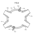
FIG. 2 is a horizontal cross-sectional view of a reactor vessel. -
FIG. 3 is a cross-sectional view of a main water nozzle. -
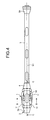
FIG. 4 is an external view of a pipe processing device according to an embodiment of the invention. -
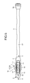
FIG. 5 is an external view while the pipe processing device illustrated inFIG. 4 is rotated about an axis by 90°. -
FIG. 6 is an external view when the pipe processing device illustrated inFIG. 4 is viewed from the front side. -
FIG. 7 is a cross-sectional view taken along the line A-A inFIG. 5 . -
FIG. 8 is a cross-sectional view taken along the line B-B inFIG. 4 . -
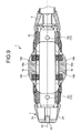
FIG. 9 is a cross-sectional view taken along the line C-C inFIG. 4 . -
FIG. 10 is a block diagram illustrating a control system of the pipe processing device according to the embodiment of the invention. -
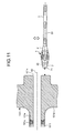
FIG. 11 is a diagram illustrating an insertion process of the pipe processing device according to the embodiment of the invention. -
FIG. 12 is a diagram illustrating an insertion process of the pipe processing device according to the embodiment of the invention. -
FIG. 13 is a diagram illustrating an insertion process of the pipe processing device according to the embodiment of the invention. -
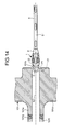
FIG. 14 is a diagram illustrating an insertion process of the pipe processing device according to the embodiment of the invention. -
FIG. 15 is a diagram illustrating an insertion process of the pipe processing device according to the embodiment of the invention. -
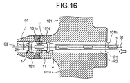
FIG. 16 is a diagram illustrating an insertion process of the pipe processing device according to the embodiment of the invention. - Hereinafter, an embodiment according to the invention will be described in detail with reference to the drawings. In addition, the invention is not limited to the embodiment. In addition, constituents in the following embodiment include a constituent which may be easily replaced by a person skilled in the art or a constituent which has substantially the same configuration.
-
FIG. 1 is a schematic diagram illustrating an example of nuclear paraphernalia, andFIG. 2 is a horizontal cross-sectional view of a reactor vessel. As illustrated inFIG. 1 , anuclear paraphernalia 100 is, for example, a pressurized water reactor (PWR). In thenuclear paraphernalia 100, areactor vessel 101, apressurizer 102, asteam generator 103, and apump 104 are sequentially connected by a primarycooling water pipe 105, to configure a circulation path of primary cooling water. In addition, a circulation path of secondary cooling water is formed between thesteam generator 103 and a turbine (not illustrated). - In the
nuclear paraphernalia 100, the primary cooling water is heated in thereactor vessel 101 to a high temperature and a high pressure, is pressurized in thepressurizer 102 to keep the pressure constant, and is supplied to thesteam generator 103 through the primarycooling water pipe 105. In thesteam generator 103, a heat exchange between the primary cooling water and the secondary cooling water is performed, and thus the secondary cooling water is evaporated to become steam. The secondary cooling water which becomes the steam by the heat exchange is supplied to the turbine. The turbine is driven by the steam of the secondary cooling water. Power of the turbine is transferred to a generator (not illustrated) to produce electric power. The steam provided for the driving of the turbine is condensed into water, which is supplied to thesteam generator 103. Meanwhile, the primary cooling water after the heat exchange is recovered in thepump 104 side through the primarycooling water pipe 105. - In the
steam generator 103, as illustrated inFIG. 1 , an inletside channel head 103a and an outletside channel head 103b are partitioned by adivider plate 103c and provided at a lower portion formed in a semispherical shape. The inletside channel head 103a and the outletside channel head 103b are partitioned from the upper portion side of thesteam generator 103 by atube sheet 103d provided at a ceiling portion thereof. On the upper portion side of thesteam generator 103, an inverted U-shaped heat-transfer tube 103e is provided. The end portion of the heat-transfer tube 103e is supported by thetube sheet 103d to connect the inletside channel head 103a and the outletside channel head 103b. In addition, the inletside channel head 103a is provided with aninlet nozzle 103f as a pipe nozzle, and theinlet nozzle 103f is connected to the primarycooling water pipe 105 on the inlet side. Meanwhile, the outletside channel head 103b is provided with anoutlet nozzle 103g as a pipe nozzle, and theoutlet nozzle 103g is connected to the primarycooling water pipe 105 on the outlet side. - As illustrated in
FIG. 1 , thereactor vessel 101 includes areactor vessel body 101a and areactor vessel head 101b mounted thereon such that a fuel assembly (not illustrated) is inserted and extracted. Thereactor vessel head 101b is provided to be opened and closed to thereactor vessel body 101a. The upper side of thereactor vessel body 101a is opened, and the lower side is formed in a semispherical shape to form a closed cylindrical shape, in which aninlet nozzle 101c and anoutlet nozzle 101d for supplying and discharging light water as the primary cooling water are provided at the upper portion thereof. Theoutlet nozzle 101d is connected to the primarycooling water pipe 105 to communicate with theinlet nozzle 103f of thesteam generator 103. In addition, theinlet nozzle 101c is connected to the primarycooling water pipe 105 to communicate with theoutlet nozzle 103g of thesteam generator 103. In addition, as illustrated inFIG. 2 , thereactor vessel 101 is provided with amain water nozzle 101e that is a pipe for main water at a position to be flush with theinlet nozzle 101c and theoutlet nozzle 101d in thereactor vessel body 101a. Themain water nozzle 101e is welded to amain water pipe 101f that is a pipe. -
FIG. 3 is a cross-sectional view of the main water nozzle. Themain water nozzle 101e is regularly inspected to secure safety or reliability of thenuclear paraphernalia 100 described above. As a result of the inspection, as illustrated inFIG. 3 , when a surface defect such as a crack caused by the secular change occurs at awelding portion 101g that is a connection portion between themain water nozzle 101e and themain water pipe 101f or when the surface defect caused by the secular change is found, thewelding portion 101g is cut or repaired. - The inspection or the process of cutting and repairing is performed, and thus the pipe processing device according to the embodiment is applied.
FIG. 4 is an external view of the pipe processing device according to the embodiment,FIG. 5 is an external view in a state where the pipe processing device illustrated inFIG. 4 is rotated about an axis by 90°,FIG. 6 is an external view of the pipe processing device illustrated inFIG. 4 viewed from the front side,FIG. 7 is a cross-sectional view taken along the line A-A inFIG. 5 ,FIG. 8 is a cross-sectional view taken along the line B-B inFIG. 4 , andFIG. 9 is a cross-sectional view taken along the line C-C inFIG. 4 . - The pipe processing device is inserted into the pipe from the
main water nozzle 101e to themain water pipe 101f in thereactor vessel 101 described above, and includes ansubject insertion body 1, aninsertion end portion 2 provided on the front side of thesubject insertion body 1 inserted into the pipe, and a fixedportion 3 provided on the back side of thesubject insertion body 1 and fixed to a manipulator having a multi-joint structure (not illustrated) as a movement mechanism 6 (seeFIG. 10 ). Theinsertion end portion 2 is configured as the pipe processing device. In addition, in the pipe processing device, theinsertion end portion 2, thesubject insertion body 1, and the fixedportion 3 are disposed in this order from the front side of the insertion along the center axis S1. In addition, in the following description, an extending direction of the center axis S1 (a direction taken along the center axis S1) is an axial direction, and a direction perpendicular to the center axis S1 is a radial direction. In addition, a direction of inserting the pipe processing device into the pipe is an insertion direction, a side directed to the insertion direction is a front side, and a reverse direction thereto is a back side. - The
insertion end portion 2 is formed with an outer diameter smaller than the inner diameters of themain water nozzle 101e and themain water pipe 101f as the pipe, and has a cylindrical shape based on the center axis S1 as illustrated inFIGS. 4 to 7 and9 . Specifically, theinsertion end portion 2 has a taperedface 2a in which the front face is substantially flat and the outer face is inclined toward the front side based on a cone shape based on the center axis S1 to be tapered toward the front side. - As illustrated in
FIGS. 5 to 7 , theinsertion end portion 2 is provided with an axialultrasonic sensor 21 and a radialultrasonic sensor 22. The axialultrasonic sensor 21 is provided at the front end of theinsertion end portion 2, and transmits and receives sonic waves in the insertion direction along the center axis S1. The radialultrasonic sensor 22 transmits and receives the sonic waves in a direction (the radial direction) intersecting (perpendicular to) the center axis S1. - As illustrated in
FIGS. 4 to 6 ,8 , and9 , thesubject insertion body 1 is configured basically with amain body portion 10 having a cylindrical shape based on the center axis S1. Themain body portion 10 is formed with an outer diameter smaller than the inner diameters of themain water nozzle 101e and themain water pipe 101f as the pipe. - As illustrated in
FIGS. 4 to 8 , thesubject insertion body 1 hassensor support portions 11. The plurality ofsensor support portions 11 is provided at symmetrical positions about the center axis S1 to extend along the axial direction and protrudes on the side portion of themain body portion 10. In the embodiment, twosensor support portions 11 are provided, and are disposed to protrude in opposing directions based on the center axis S1. In addition, although not illustrated in the figures, for example, when threesensor support portions 11 are provided, they are equally disposed in the circumferential direction based on the center axis S1. - The
sensor support portion 11 is provided with a plurality of inspectionultrasonic sensors 111 along the axial direction. In the embodiment, onesensor support portion 11 is provided with three inspectionultrasonic sensors 111 along the axial direction. The inspectionultrasonic sensor 111 transmits and receives sonic waves in a direction intersecting with the center axis S1. In addition, when thesubject insertion body 1 is inserted into the pipe, the individual inspectionultrasonic sensors 111 transmit and receive the sonic waves at different angles with respect to the direction (the radial direction) perpendicular to the center axis S1. This is because, when the sonic waves are transmitted and received at a single angle, reception sensitivity is decreased when there is a defect in the same direction as the angle, and thus the defect may not be detected. That is, the plurality of sonic waves is transmitted and received at different angles, and thus the detection precision is thereby improved. - In addition, as illustrated in
FIG. 7 , thesubject insertion body 1 has aslide movement portion 12. Theslide movement portion 12 has asupport member 12a extending along the axial direction. Thesupport member 12a supports thesensor support portion 11. In addition, theslide movement portion 12 hasslide portions 12b provided to protrude to the side portion of themain body portion 10 outside both ends of thesensor support portion 11, at both ends of thesupport member 12a. In addition, theslide movement portion 12 has aslide shaft 12c. Theslide shaft 12c extends in the direction perpendicular to the center axis S1 and is fixed to themain body portion 10. Theslide portion 12b is slidably inserted into the extending direction of theslide shaft 12c. For this reason, theslide movement portion 12 is provided slidably in the direction perpendicular to the center axis S1 in which theslide shaft 12c extends. That is, thesensor support portion 11 supported by theslide movement portion 12 is provided slidably in the radial direction. In addition, theslide movement portion 12 has acompression coil spring 12d. Thecompression coil spring 12d is inserted through theslide shaft 12c, and comes in contact with theslide portion 12b. For this reason, theslide movement portion 12 is elastically biased toward the outside of themain body portion 10 in the extending direction of theslide shaft 12c, which is the radial direction, by thecompression coil spring 12d. That is, thesensor support portion 11 supported by theslide movement portion 12 is elastically biased in the protruding direction, which is the radial direction, on the outside of themain body portion 10. In addition, theslide movement portion 12 is provided with theslide portions 12b on both ends of thesupport member 12a. Eachslide portion 12b is slidably movable along theslide shaft 12c, and is elastically biased toward the outside of themain body portion 10 by thecompression coil spring 12d. For this reason, in theslide movement portion 12, one end side and the other end side in the axial direction are elastically biased to be slidably movable. That is, in thesensor support portion 11, one end side and the other end side in the axial direction are elastically biased to be slidably movable. In addition, a dimension H1 between the outer faces of thesensor support portions 11 elastically biased toward the outside of themain body portion 10 is larger than the inner diameter of the pipe to be inserted. - In addition, as illustrated in
FIGS. 7 and8 , thesubject insertion body 1 has atilt movement portion 13. Thetilt movement portion 13 has a bearingmember 13a erected along both sides of thesensor support portion 11 in thesupport member 12a, and arotation shaft 13b extending in the radial direction with respect to the bearingmember 13a and inserted into the substantially center of the extending direction of thesensor support portion 11. For this reason, thesensor support portion 11 is supported to be tiltable in the front and back direction of the insertion direction with respect to theslide movement portion 12. In addition, when theslide movement portion 12 is not provided, thetilt movement portion 13 is provided in themain body portion 10, and supports thesensor support portion 11 to be tiltable in the front and back direction of the insertion direction. - In addition, the
tilt movement portion 13 has atilt biasing portion 14. Thetilt biasing portion 14 is configured as a spring plunger and is fixed to thesupport member 12a. The plunger portion comes in contact with the back side of thesensor support portion 11, which is supported by thetilt movement portion 13, in the insertion direction and elastically biases thesensor support portion 11 on the outside of thesubject insertion body 1. That is, thesensor support portion 11 supported to be tiltable in the front and back direction of the insertion by thetilt movement portion 13 is elastically biased in the front direction. In addition, when theslide movement portion 12 is not provided, thetilt biasing portion 14 is provided in themain body portion 10 and elastically biases thesensor support portion 11 in the front direction of the insertion. - In addition, as illustrated in
FIG. 8 , thesubject insertion body 1 has acircumferential movement portion 15. Thecircumferential movement portion 15 is formed such that at least a radial inner diameter of a hole on thesensor support portion 11 side through which therotation shaft 13b is inserted is larger than the outer diameter of therotation shaft 13b, in thetilt movement portion 13. That is, thesensor support portion 11 is supported movably in the radial direction with respect to therotation shaft 13b by thecircumferential movement portion 15, which is a hole with a large diameter. For this reason, thesensor support portion 11 is allowed to move in the circumferential direction of the center axis S1 with respect to therotation shaft 13b, and is supported to be tiltable in the circumferential direction. In addition, when thetilt movement portion 13 is not provided, thecircumferential movement portion 15 supports thesensor support portion 11 to be tiltable in the circumferential direction by a configuration of a rail extending in the circumferential direction with respect to thesupport member 12a of theslide movement portion 12, and a slider slid with the rail although not illustrated in the figures. In addition, when theslide movement portion 12 is not provided, thecircumferential movement portion 15 supports thesensor support portion 11 to be tiltable in the circumferential direction with respect to thetilt movement portion 13 provided in themain body portion 10 as described above. In addition, thetilt movement portion 13 and theslide movement portion 12 are not provided, thecircumferential movement portion 15 supports thesensor support portion 11 to be tiltable in the circumferential direction by a configuration of a rail extending in the circumferential direction with respect to themain body portion 10, and a slider slid with the rail. - In addition, the
sensor support portion 11 has asensor extrusion portion 16. Thesensor extrusion portion 16 is provided when at least three inspectionultrasonic sensors 111 are disposed along the center axis S1, and supports an inspectionultrasonic sensor 111a positioned on the intermediate side to protrude from the outer face in the radial direction and to be slidable with respect to thesensor support portion 11. Thesensor extrusion portion 16 is configured as the compression coil spring elastically biasing the inspectionultrasonic sensor 111a on the outside. In addition, in the inspectionultrasonic sensor 111a, slide movement is restricted with respect to thesensor support portion 11 so as not to come out of the outside of thesensor support portion 11. - In addition, as illustrated in
FIGS. 4 to 6 ,8 , and9 , thesubject insertion body 1 hasprotrusion portions 18. The plurality ofprotrusion portions 18 is provided to protrude in the radial direction on the side portion of thesubject insertion body 1 and at symmetrical positions about the center axis S1. In the embodiment, twoprotrusion portions 18 are provided, and are disposed to protrude in the opposing direction based on the center axis S1. In addition, although not illustrated in the figures, for example, when threeprotrusion portions 18 are provided, they are equally disposed in the circumferential direction based on the center axis S1. Theprotrusion portions 18 are provided to be slidably movable in the radial direction by aslide support portion 18a, with respect to themain body portion 10. In addition, theprotrusion portions 18 are elastically biased in the direction protruding in the radial direction, which is the slide direction, by acompression coil spring 18b. In addition, as illustrated inFIG. 9 , a plurality (two in the embodiment) ofcompression coil springs 18b are provided in the axial direction. For this reason, theprotrusion portion 18 can be tilted and moved back and forth in the axial direction while being elastically biased. In addition, a dimension H2 between the outer faces of theprotrusion portions 18 elastically biased toward the outside of themain body portion 10 is larger than the inner diameter of the pipe to be inserted. - In addition, it is preferable that the
protrusion portions 18 be equally disposed in the circumferential direction based on the center axis S1 with thesensor support portion 11. - In addition, in the pipe processing device, at least one of outer corners of the
subject insertion body 1, theinsertion end portion 2, thesensor support portion 11, or theprotrusion portion 18 is arc- or chamfered-processed. - In addition, the fixed
portion 3 is provided through ajoint portion 4 having a shape in which the front and back of theinsertion end portion 2 are reversed, on the back side of thesubject insertion body 1. The fixedportion 3 is a pipe-shaped member extending backward, and is formed with a diameter smaller than the outer diameter of the front end of theinsertion end portion 2 formed to be tapered. Aconnection portion 3a of the back end of the fixedportion 3 is mounted on themovement mechanism 6. For this reason, the pipe processing device is moved in the axial direction along the center axis S1, in the radial direction perpendicular to the axial direction, in the rotation direction of rotating around the center axis S1, and in the oblique direction oblique with respect to the center axis S1, by themovement mechanism 6. -
FIG. 10 is a block diagram of a control system of the pipe processing device according to the embodiment, andFIGS. 11 to 16 are diagrams illustrating an insertion process of the pipe processing device according to the embodiment. - As illustrated in
FIG. 10 , in the pipe processing device described above, the axialultrasonic sensor 21 and the radialultrasonic sensor 22 described above are connected to acontrol unit 5. In addition, in the pipe processing device, the inspectionultrasonic sensors 111 described above are connected to thecontrol unit 5. In addition, in the pipe processing device, themovement mechanism 6 moving the pipe processing device is connected. As described above, themovement mechanism 6 is configured as the manipulator with the multi-joint structure, and includes anaxial movement portion 61 moving the pipe processing device in the axial direction, aradial movement portion 62 moving the pipe processing device in the radial direction, a rotation-direction movement portion 63 moving the pipe processing device in the rotation direction, and an oblique-direction movement portion 64 moving the pipe processing device in the oblique direction. Theaxial movement portion 61, theradial movement portion 62, the rotation-direction movement portion 63, and the oblique-direction movement portion 64 are connected to thecontrol unit 5. - The
control unit 5 is configured by a microcomputer or the like, and controls theaxial movement portion 61, theradial movement portion 62, the rotation-direction movement portion 63, and the oblique-direction movement portion 64 of themovement mechanism 6, according to detection results of the axialultrasonic sensor 21 and the radialultrasonic sensor 22. In addition, thecontrol unit 5 inputs the detection result of each inspectionultrasonic sensor 111, and stores inspection information of the pipe. - Specifically, an operation of the pipe processing device by the
control unit 5 will be described. Herein, in order to secure safety or reliability of thenuclear paraphernalia 100 described above, a process of inspecting thewelding portion 101g that is the connection portion between themain water nozzle 101e and themain water pipe 101f in thereactor vessel 101 will be described. The inside of the pipes (themain water nozzle 101e and themain water pipe 101f) that are the inspection subject is in a state filled with water, and themovement mechanism 6 and the pipe processing device mounted on themovement mechanism 6 are disposed in the water. In addition, the position information of the pipe and the internal structure information of the pipe are stored in advance in thecontrol unit 5 and themovement mechanism 6 moves the pipe processing device basically based on the information stored in thecontrol unit 5. - First, as illustrated in
FIG. 11 , thesubject insertion body 1 is disposed at a position for detecting the distance from the outer edge of anopening portion 101h of the pipe by the axialultrasonic sensor 21. The axialultrasonic sensor 21 detects the distance from the outer edge of theopening portion 101h of the pipe, and thus it is possible to recognize the position of the pipe processing device with respect to the outer edge of theopening portion 101h of the pipe. - Then, as illustrated in
FIG. 12 , thesubject insertion body 1 is moved in the radial direction from the position ofFIG. 11 to the position where the distance detected by the axialultrasonic sensor 21 is larger than the outer edge of theopening portion 101h of the pipe. That the distance is larger than the outer edge of theopening portion 101h of the pipe means that theopening portion 101h of the pipe is detected. That is, the axialultrasonic sensor 21 detects the distance larger than the outer edge of theopening portion 101h of the pipe, and thus it is possible to recognize theopening portion 101h of the pipe. The center axis S1 of thesubject insertion body 1 is aligned with the position of the center axis S2 of the pipe based on the position information of the pipe stored in advance. Herein, since it is difficult to confirm the accurate position of the center axis S2 of the pipe, the center axis S1 of thesubject insertion body 1 may not coincide with the center axis S2 of the pipe. - Then, as illustrated in
FIG. 13 , thesubject insertion body 1 is moved in the axial direction from the position ofFIG. 12 to the position where the inner face of the pipe is detected by the radialultrasonic sensor 22. Theinsertion end portion 2 provided with the radialultrasonic sensor 22 has the diameter smaller than the inner diameter of the pipe, and is formed to be tapered. In addition, at the position where the inner face of the pipe is detected by the radialultrasonic sensor 22, thesubject insertion body 1 has not been inserted into the pipe yet. For this reason, theinsertion end portion 2 and thesubject insertion body 1 do not come in contact with the pipe. - Then, as illustrated in
FIG. 14 , at the position ofFIG. 13 , the distances from the inner face of the pipe are detected by the radialultrasonic sensor 22 while rotating thesubject insertion body 1 in the rotation direction. Thesubject insertion body 1 is moved in the radial direction to the position where the distances are the same. Herein, when the cross section of the pipe is circular, thesubject insertion body 1 is moved in the radial direction to the position where all the distances are the same. In addition, when the cross section of the pipe is elliptical, thesubject insertion body 1 is moved in the radial direction to the position where the distances opposing each other are the same. For this reason, a detection point P1 by the radialultrasonic sensor 22 on the center axis S1 of thesubject insertion body 1 coincides with the center axis S2 of the pipe. - Then, as illustrated in
FIG. 15 , thesubject insertion body 1 is moved in the axial direction by a predetermined distance from the position ofFIG. 14 , and then the distances from the inner face of the pipe are detected by the radialultrasonic sensor 22 while rotating thesubject insertion body 1 in the rotation direction. Thesubject insertion body 1 is moved in the radial direction to the position where the distances are the same. Herein, the predetermined distance means a range in which thesubject insertion body 1 has not been inserted into the pipe yet. For this reason, a detection point P2 by the radialultrasonic sensor 22 on the center axis S1 of thesubject insertion body 1 coincides with the center axis S2 of the pipe. - Then, as illustrated in
FIG. 16 , thesubject insertion body 1 is moved in the oblique direction to the position where the center axis S1 coincides with the line connecting two points P1 and P2 with the same distance from the inner face of the pipe. That is, since the line connecting the points P1 and P2 detected in advance coincides with the center axis S2 of the pipe and the center axis S1 of thesubject insertion body 1 is simply oblique with respect to the center axis S2, the center axis S1 coincides with the center axis S2 by allowing the center axis S1 of thesubject insertion body 1 to coincide with the line connecting the points P1 and P2. Thereafter, thesubject insertion body 1 is moved in the axial direction to insert thesubject insertion body 1 into the pipe. Accordingly, in the state where the center axis S1 coincides with the center axis S2, thesubject insertion body 1 is inserted into the pipe. - As described above, the
subject insertion body 1 is inserted into the pipe, and the pipe is thereby inspected by the inspectionultrasonic sensors 111. - The pipe processing device of the embodiment is a pipe processing device in which the
subject insertion body 1 inserted from theopening portion 101h of the pipe into the pipe is provided to be movable by themovement mechanism 6 in the axial direction along the center axis S1 of thesubject insertion body 1, the radial direction perpendicular to the center axis S1, the rotation direction of rotating around the center axis S1, and the oblique direction oblique with respect to the center axis S1. The pipe processing device includes theinsertion end portion 2 that is provided on the front side of thesubject insertion body 1 inserted into the pipe and is formed with the outer diameter smaller than inner diameter of the pipe, the axialultrasonic sensor 21 that transmits and receives the sonic waves in the insertion direction with respect to the front end of theinsertion end portion 2, the radialultrasonic sensor 22 that transmits and receives the sonic waves in the direction intersecting the center axis S1 on the side portion of theinsertion end portion 2, and thecontrol unit 5 that controls themovement mechanism 6 according to the detection results of the axialultrasonic sensor 21 and the radialultrasonic sensor 22. - According to the pipe processing device, the subject insertion body 1 is disposed at a position of detecting a distance from the outer edge of the opening portion 101h of the pipe by the axial ultrasonic sensor 21; the subject insertion body 1 is moved in a radial direction to a position where the distance detected by the axial ultrasonic sensor 21 is larger than the outer edge of the opening portion 101h of the pipe; the subject insertion body 1 is moved in an axial direction to a position where the inner face of the pipe is detected by the radial ultrasonic sensor 22; a distance is detected from the inner face of the pipe by the radial ultrasonic sensor 22 while the subject insertion body 1 is rotated in a rotation direction, and the subject insertion body 1 is moved in a radial direction to a position where the distance is the same; the subject insertion body 1 is moved in an axial direction by a predetermined distance, a distance is detected from the inner face of the pipe by the radial ultrasonic sensor 22 while the subject insertion body 1 is rotated in a rotation direction, and the subject insertion body 1 is moved in a radial direction to a position where the distance is the same; and the subject insertion body 1 is moved in an oblique direction to a position where the center axis S1 matches a line connecting the two points P1 and P2 with the same distance from the inner face of the pipe, and the subject insertion body 1 is moved in an axial direction to insert the subject insertion body 1 into the pipe. For this reason, the
subject insertion body 1 is inserted into the pipe with the center axis S1 matching the center axis S2 of the pipe. As a result, it is possible to guide thesubject insertion body 1 for insertion so that the subject insertion body passes through the center of the pipe. - In addition, in the pipe processing device of the embodiment, the
insertion end portion 2 is formed to be tapered toward the front side. - According to the pipe processing device, the
subject insertion body 1 is moved in the axial direction to the position where the inner face of the pipe is detected by the radialultrasonic sensor 22, the distance from the inner face of the pipe is detected by the radialultrasonic sensor 22 while thesubject insertion body 1 is rotated in the rotation direction, thesubject insertion body 1 is moved in the radial direction to the position where the distance is the same, thesubject insertion body 1 is moved in the axial direction by the predetermined distance, the distance from the inner face of the pipe is detected by the radialultrasonic sensor 22 while thesubject insertion body 1 is rotated in the rotation direction, thesubject insertion body 1 is moved in the radial direction to the position where the distance is the same, and thesubject insertion body 1 is moved in the oblique direction to the position where the center axis S1 matches the line connecting the two points P1 and P2 with the same distance from the inner face of the pipe. In this case, it is possible to prevent theinsertion end portion 2 from coming in contact with the inner face of the pipe. As a result, it is possible to move thesubject insertion body 1 to the more accurate position. - The pipe processing device of the embodiment is provided with the
sensor support portion 11 that is provided on the side portion of thesubject insertion body 1, in which the plurality of inspectionultrasonic sensors 111 transmitting and receiving the sonic waves in the direction intersecting the center axis S1 is disposed along the center axis S1. The plurality ofsensor support portions 11 is provided at the symmetrical positions based on the center axis S1. - According to the pipe processing device, it is possible to move the inspection
ultrasonic sensor 111 along the inner face of the pipe, and to inspect the pipe with high precision. - In addition, in the pipe processing device of the embodiment, the
sensor support portion 11 is supported to be slidable in the radial direction perpendicular to the center axis S1, and is elastically biased in the protrusion direction. - According to the pipe processing device, since the
sensor support portion 11 comes in contact with the inner face of the pipe, it is possible to move the inspectionultrasonic sensor 111 with the sensor coming in contact with the inner face of the pipe, and to inspect the pipe with high precision. In addition, since thesensor support portion 11 is moved in the radial direction along the unevenness of the inner face of the pipe, it is possible to allow the inspectionultrasonic sensor 111 to follow the shape of the inner face of the pipe, and to inspect the pipe with high precision. - In addition, in the pipe processing device of the embodiment, the
sensor support portion 11 is supported to be tiltable in the front and back direction of the insertion. - According to the pipe processing device, since the
sensor support portion 11 is moved in the front and back direction along the unevenness of the inner face of the pipe, it is possible to allow the inspectionultrasonic sensor 111 to follow the shape of the inner face of the pipe, and to inspect the pipe with high precision. - In addition, in the pipe processing device of the embodiment, the
sensor support portion 11 supported to be tiltable in the front and back direction is elastically biased in the front direction. - According to the pipe processing device, since the front side of the subject insertion body is tapered such that the
sensor support portion 11 is inclined to the front side when thesubject insertion body 1 is inserted into the pipe, it is possible to smoothly perform the insertion. In the state where thesubject insertion body 1 is inserted into the pipe, since thesensor support portion 11 is moved in the front and back direction along the unevenness of the inner face of the pipe, it is possible to allow the inspectionultrasonic sensor 111 to follow the shape of the inner face of the pipe, and to inspect the pipe with high precision. In addition, since thesensor support portion 11 is elastically biased in the state tilted in the front direction, it is possible to substitute the inspectionultrasonic sensor 111 as the radial ultrasonic sensor at the time of insertion when the inspectionultrasonic sensor 111 on the front side of thesensor support portion 11 is disposed at a distance from the inner face of the pipe. - In addition, in the pipe processing device of the embodiment, the
sensor support portion 11 is supported to be tiltable in the circumferential direction. - According to the pipe processing device, since the
sensor support portion 11 is moved in the circumferential direction along the unevenness of the inner face of the pipe, it is possible to allow the inspectionultrasonic sensor 111 to follow the shape of the inner face of the pipe, and to inspect the pipe with high precision. - In addition, in the pipe processing device of the embodiment, at least three inspection
ultrasonic sensors 111 are disposed along the center axis S1 with respect to thesensor support portion 11, and the inspectionultrasonic sensor 111a positioned on the intermediate side is supported to be slidable in the protrusion direction from the outer face of thesensor support portion 11 and is elastically biased in the protrusion direction. - Since a plurality of sonic waves is transmitted and received at different angles due to arranging the plurality of inspection
ultrasonic sensors 111, precision in detection is improved. When at least three inspectionultrasonic sensors 111 are disposed, the inspectionultrasonic sensor 111a on the intermediate side may be separated from the inner face of the pipe by the unevenness of the inner face of the pipe. From this point, according to the pipe processing device, since the inspectionultrasonic sensor 111a positioned on the intermediate side is elastically biased to protrude from the outer face of thesensor support portion 11, the inspectionultrasonic sensor 111a positioned on the intermediate side is prevented from being separated from the inner face of the pipe by the unevenness of the inner face of the pipe, and hence it is possible to inspect the pipe with high precision. - In addition, in the pipe processing device of the embodiment, the plurality of
protrusion portions 18 provided to protrude on the side portion of thesubject insertion body 1 is provided at the symmetrical positions based on the center axis S1, is supported to be slidable in the radial direction perpendicular to the center axis S1, and is elastically biased in the protrusion direction. - According to the pipe processing device, since the
protrusion portion 18 is moved in the radial direction along the unevenness of the inner face of the pipe while coming in contact with the inner face of the pipe, it is possible to keep the state where the center axis S1 matches the center axis S2 of the pipe. - In addition, in the pipe processing device of the embodiment, the
protrusion portions 18 are equally disposed in the circumferential direction based on the center axis S1 with thesensor support portions 11. - According to the pipe processing device, since each
protrusion portion 18 and eachsensor support portion 11 are equally disposed in the circumferential direction in the pipe, it is possible to stably keep the state where the center axis S1 coincides with the center axis S2 of the pipe. - In addition, in the pipe processing device of the embodiment, at least one outer corner of the
subject insertion body 1, theinsertion end portion 2, thesensor support portion 11, or theprotrusion portion 18 is arc or chamfered-processed. - According to the pipe processing device, it is possible to smoothly move the device in a case of the insertion into the pipe, the movement in the pipe, and the extraction of the device from the pipe.
- In addition, according to the embodiment, there is provided a pipe processing method for moving any one pipe processing device described above by the movement mechanism 6 to insert the pipe processing device from the opening portion 101h of the pipe into the pipe, the method including: disposing the subject insertion body 1 at a position of detecting a distance from the outer edge of the opening portion 101h of the pipe by the axial ultrasonic sensor 21; moving the subject insertion body 1 in a radial direction to a position where the distance detected by the axial ultrasonic sensor 21 is larger than the outer edge of the opening portion 101h of the pipe; moving the subject insertion body 1 in an axial direction to a position where the inner face of the pipe is detected by the radial ultrasonic sensor 22; detecting a distance from the inner face of the pipe by the radial ultrasonic sensor 22 while rotating the subject insertion body 1 in a rotation direction, and moving the subject insertion body 1 in a radial direction to a position where the distance is the same; moving the subject insertion body 1 in an axial direction by a predetermined distance, detecting a distance from the inner face of the pipe by the radial ultrasonic sensor 22 while rotating the subject insertion body 1 in a rotation direction, and moving the subject insertion body 1 in a radial direction to a position where the distance is the same; and moving the subject insertion body 1 in an oblique direction to a position where the center axis S1 matches a line connecting the two points P1 and P2 with the same distance from the inner face of the pipe, and moving the subject insertion body 1 in a rotation direction to insert the subject insertion body 1 into the pipe.
- According to the pipe processing method, the
subject insertion body 1 is inserted into the pipe in the state where the center axis S1 is matched with the center axis S2 of the pipe. As a result, it is possible to guide thesubject insertion body 1 for insertion so that thesubject insertion body 1 passes through the center of the pipe. - In addition, in the embodiment, as the pipe processing device, the pipe inspecting device provided with the inspection
ultrasonic sensor 111 has been described by way of example. However, when a mechanism that performs a cutting process is provided instead of the inspectionultrasonic sensor 111, it is possible to perform the process of the pipe with high precision as the pipe processing device. -
- 1
- SUBJECT INSERTION BODY
- 2
- INSERTION END PORTION
- 2a
- TAPERED FACE
- 21
- AXIAL ULTRASONIC SENSOR
- 22
- RADIAL ULTRASONIC SENSOR
- 3
- FIXED PORTION
- 4
- JOINT PORTION
- 5
- CONTROL UNIT
- 6
- MOVEMENT MECHANISM
- 61
- AXIAL MOVEMENT PORTION
- 62
- RADIAL MOVEMENT PORTION
- 63
- ROTATION-DIRECTION MOVEMENT PORTION
- 64
- OBLIQUE-DIRECTION MOVEMENT PORTION
- 10
- MAIN BODY PORTION
- 11
- SENSOR SUPPORT PORTION
- 111 (111a)
- INSPECTION ULTRASONIC SENSOR
- 12
- SLIDE MOVEMENT PORTION
- 12a
- SUPPORT MEMBER
- 12b
- SLIDE PORTION
- 12c
- SLIDE SHAFT
- 12d
- COMPRESSION COIL SPRING
- 13
- TILT MOVEMENT PORTION
- 13a
- BEARING MEMBER
- 13b
- ROTATION SHAFT
- 14
- TILT BIASING PORTION
- 15
- CIRCUMFERENTIAL MOVEMENT PORTION
- 16
- SENSOR EXTRUSION PORTION
- 18
- PROTRUSION PORTION
- 18a
- SLIDE SUPPORT PORTION
- 18b
- COMPRESSION COIL SPRING
- 101e
- MAIN WATER NOZZLE
- 101f
- MAIN WATER PIPE
- 101h
- OPENING PORTION
- P1, P2
- DETECTION POINT
- S1
- CENTER AXIS OF DEVICE
- S2
- CENTER AXIS OF PIPE
Claims (12)
- A pipe processing device provided with an subject insertion body, which is inserted into a pipe from an opening portion of the pipe, to be movable by a movement mechanism in an axial direction along a center axis of the subject insertion body, a radial direction perpendicular to the center axis, a rotation direction of rotating about the center axis, and an oblique direction oblique with respect to the center axis, the pipe processing device comprising:an insertion end portion that is provided on a front side of the subject insertion body to be inserted into the pipe and is formed in a smaller outer diameter than an inner diameter of the pipe;an axial ultrasonic sensor that transmits and receives a sonic wave in an insertion direction with respect to a front end of the insertion end portion;a radial ultrasonic sensor that transmits and receives a sonic wave in a direction intersecting the center axis at a side portion of the insertion end portion; anda control unit that controls the movement mechanism according to detection results of the axial ultrasonic sensor and the radial ultrasonic sensor.
- The pipe processing device according to claim 1, wherein the insertion end portion is formed to be tapered toward the front side.
- The pipe processing device according to claim 1 or 2, further comprising:a sensor support portion that is provided on the side portion of the subject insertion body and in which a plurality of inspection ultrasonic sensors transmitting and receiving a sonic wave in a direction intersecting the center axis is disposed along the center axis,wherein a plurality of the sensor support portions is provided at symmetrical positions about the center axis.
- The pipe processing device according to claim 3, wherein the sensor support portions are supported to be slidable in a radial direction perpendicular to the center axis, and are elastically biased in a protrusion direction.
- The pipe processing device according to claim 3, wherein the sensor support portions are supported to be tiltable in a front and back direction of insertion.
- The pipe processing device according to claim 5, wherein the sensor support portions supported to be tiltable in the front and back direction are elastically biased in the front direction.
- The pipe processing device according to claim 3, wherein the sensor support portions are supported to be tiltable in a circumferential direction.
- The pipe processing device according to claim 3, wherein at least three inspection ultrasonic sensors are disposed along the center axis with respect to the sensor support portions, and the inspection ultrasonic sensor positioned on the intermediate side is supported to be slidable in a protrusion direction from an outer face of the sensor support portion and is elastically biased in the protrusion direction.
- The pipe processing device according to claim 3, wherein a plurality of protrusion portions provided to protrude on the side portion of the subject insertion body is provided at symmetrical positions about the center axis, is supported to be slidable in a radial direction perpendicular to the center axis, and is elastically biased in a protrusion direction.
- The pipe processing device according to claim 9, wherein the protrusion portions are equally disposed in a circumferential direction about the center axis as a reference along with the sensor support portions.
- The pipe processing device according to claim 9, wherein at least one outer corner of the subject insertion body, the insertion end portion, the sensor support portion, or the protrusion portion is arc or chamfered-processed.
- A pipe processing method for moving the pipe processing device according to any one of claims 1 to 11 by the movement mechanism to insert the pipe processing device from the opening portion of the pipe into the pipe, the method comprising:disposing the subject insertion body at a position of detecting a distance from an outer edge of the opening portion of the pipe by the axial ultrasonic sensor;moving the subject insertion body in a radial direction to a position where the distance detected by the axial ultrasonic sensor is larger than the outer edge of the opening portion of the pipe;moving the subject insertion body in an axial direction to a position where an inner face of the pipe is detected by the radial ultrasonic sensor;detecting a distance from the inner face of the pipe by the radial ultrasonic sensor while rotating the subject insertion body in a rotation direction, and moving the subject insertion body in a radial direction to a position where the distance is the same;moving the subject insertion body in an axial direction by a predetermined distance, detecting a distance from the inner face of the pipe by the radial ultrasonic sensor while rotating the subject insertion body in a rotation direction, and moving the subject insertion body in a radial direction to a position where the distance is the same; andmoving the subject insertion body in an oblique direction to a position where the center axis coincides with a line connecting two points with the same distance from the inner face of the pipe and moving the subject insertion body in an axial direction to insert the subject insertion body into the pipe.
Applications Claiming Priority (2)
| Application Number | Priority Date | Filing Date | Title |
|---|---|---|---|
| JP2011083116A JP5713766B2 (en) | 2011-04-04 | 2011-04-04 | Piping processing apparatus and piping processing method |
| PCT/JP2012/054133 WO2012137551A1 (en) | 2011-04-04 | 2012-02-21 | Pipe treatment device and pipe treatment method |
Publications (3)
| Publication Number | Publication Date |
|---|---|
| EP2696198A1 true EP2696198A1 (en) | 2014-02-12 |
| EP2696198A4 EP2696198A4 (en) | 2014-12-31 |
| EP2696198B1 EP2696198B1 (en) | 2019-03-20 |
Family
ID=46968955
Family Applications (1)
| Application Number | Title | Priority Date | Filing Date |
|---|---|---|---|
| EP12767561.9A Active EP2696198B1 (en) | 2011-04-04 | 2012-02-21 | Pipe treatment device and pipe treatment method |
Country Status (4)
| Country | Link |
|---|---|
| US (1) | US9285346B2 (en) |
| EP (1) | EP2696198B1 (en) |
| JP (1) | JP5713766B2 (en) |
| WO (1) | WO2012137551A1 (en) |
Cited By (1)
| Publication number | Priority date | Publication date | Assignee | Title |
|---|---|---|---|---|
| WO2023240052A1 (en) * | 2022-06-09 | 2023-12-14 | Ge-Hitachi Nuclear Energy Americas Llc | Process and tools to perform reactor pressure vessel nozzle expansion mitigating primary coolant leakage |
Families Citing this family (4)
| Publication number | Priority date | Publication date | Assignee | Title |
|---|---|---|---|---|
| JPH0754186B2 (en) | 1991-07-31 | 1995-06-07 | 株式会社フジマック | Rotating chamber type combined heating device |
| US9279582B2 (en) * | 2013-05-10 | 2016-03-08 | Westinghouse Electric Company Llc | Method and apparatus for delivering a tool to the interior of a heat exchange tube |
| CN117862057B (en) * | 2024-01-12 | 2024-07-19 | 中国水利水电第三工程局有限公司 | Prefabrication method for pressure pipeline of pumped storage power station |
| CN119124997B (en) * | 2024-08-21 | 2025-12-05 | 中广核检测技术有限公司 | Centering equipment and methods for inspecting the outer wall of penetrating components |
Family Cites Families (11)
| Publication number | Priority date | Publication date | Assignee | Title |
|---|---|---|---|---|
| US3600613A (en) * | 1968-08-22 | 1971-08-17 | Branson Instr | Transducer probe for ultrasonic pulse-echo test apparatus |
| DE2557992C3 (en) * | 1975-12-22 | 1978-06-29 | Kraftwerk Union Ag, 4330 Muelheim | Test system carrier for testing the connection nozzle area in pressure vessels, especially reactor pressure vessels of nuclear power plants with ultrasound |
| DE2640055C3 (en) * | 1976-09-06 | 1979-07-19 | Kraftwerk Union Ag, 4330 Muelheim | Tube crimping manipulator, especially for ultrasonic testing in nuclear reactor systems |
| US4196049A (en) * | 1977-03-25 | 1980-04-01 | Westinghouse Electric Corp. | Segmented articulating manipulator arm for nuclear reactor vessel inspection apparatus |
| US4302286A (en) * | 1979-04-24 | 1981-11-24 | Westinghouse Electric Corp. | Reactor vessel in-service inspection assembly and ultrasonic centering device |
| JPH02291957A (en) * | 1989-05-02 | 1990-12-03 | Ishikawajima Harima Heavy Ind Co Ltd | Heat-exchanger inspecting apparatus |
| JPH0333651A (en) * | 1989-06-30 | 1991-02-13 | Chubu Electric Power Co Inc | Automatic inspection apparatus |
| JP3468785B2 (en) * | 1992-09-07 | 2003-11-17 | 三菱重工業株式会社 | Rotary ultrasonic probe holder |
| JPH08211034A (en) * | 1995-02-06 | 1996-08-20 | Mitsubishi Heavy Ind Ltd | Piping inspecting probe |
| JP5172625B2 (en) * | 2008-11-21 | 2013-03-27 | 株式会社東芝 | Piping inspection device and piping inspection method |
| JP5737869B2 (en) * | 2010-06-25 | 2015-06-17 | 三菱重工業株式会社 | Pipe inner surface inspection device |
-
2011
- 2011-04-04 JP JP2011083116A patent/JP5713766B2/en active Active
-
2012
- 2012-02-21 WO PCT/JP2012/054133 patent/WO2012137551A1/en not_active Ceased
- 2012-02-21 EP EP12767561.9A patent/EP2696198B1/en active Active
- 2012-02-21 US US13/990,477 patent/US9285346B2/en active Active
Cited By (2)
| Publication number | Priority date | Publication date | Assignee | Title |
|---|---|---|---|---|
| WO2023240052A1 (en) * | 2022-06-09 | 2023-12-14 | Ge-Hitachi Nuclear Energy Americas Llc | Process and tools to perform reactor pressure vessel nozzle expansion mitigating primary coolant leakage |
| US12573513B2 (en) | 2022-06-09 | 2026-03-10 | Ge-Hitachi Nuclear Energy Americas Llc | Process and tools to perform reactor pressure vessel nozzle expansion mitigating primary coolant leakage |
Also Published As
| Publication number | Publication date |
|---|---|
| EP2696198A4 (en) | 2014-12-31 |
| JP5713766B2 (en) | 2015-05-07 |
| JP2012220218A (en) | 2012-11-12 |
| WO2012137551A1 (en) | 2012-10-11 |
| US9285346B2 (en) | 2016-03-15 |
| US20130239688A1 (en) | 2013-09-19 |
| EP2696198B1 (en) | 2019-03-20 |
Similar Documents
| Publication | Publication Date | Title |
|---|---|---|
| EP2696198B1 (en) | Pipe treatment device and pipe treatment method | |
| US8365584B1 (en) | Apparatus for inspecting turbomachine components in-situ | |
| US8331522B2 (en) | Maintenance and repair device for structure inside nuclear reactor | |
| US20120193065A1 (en) | Inspection apparatus and inspection method for heat transfer tube | |
| JP4357298B2 (en) | Device for remote inspection of steam generation tubes | |
| EP2772334A2 (en) | Weld portion repairing method and weld portion repairing apparatus | |
| JPH0280949A (en) | Nondestructive ultrasonic test apparatus of circular welding section of inside of tube of steam generator | |
| EP2626624A1 (en) | Device for monitoring thickness reduction of inner surface in heat transfer pipe or inner surface in evaporation pipe | |
| CN108291894B (en) | Method, system and fixture for inspecting gasket welds | |
| JP3256692B2 (en) | Elbow weld inspection system and elbow weld inspection method | |
| US20120183114A1 (en) | Method and apparatus for testing an annular weld on a main coolant line connected to a reactor pressure vessel of a nuclear power plant | |
| US10020080B2 (en) | Nuclear reactor nozzle repair method | |
| WO2014132678A1 (en) | Water jet peening device | |
| US8779762B2 (en) | Inspection device | |
| US20180306636A1 (en) | Inspection system for turbine rotors | |
| JP6104636B2 (en) | Inspection method and inspection apparatus | |
| KR101513776B1 (en) | Foreign removal system for steam generator of nuclear power plant | |
| KR101752585B1 (en) | shrink device for heat pipe or steam generator | |
| JP2012210696A (en) | Cutting apparatus | |
| JP2013040785A (en) | Dimension measuring instrument and dimension measuring method | |
| JP2013057640A (en) | Inspection device | |
| Glass et al. | Robotics and manipulators for reactor pressure vessel head inspection | |
| Zhang et al. | Research on the positioning strategy for CRDM penetrations in reactor vessel head | |
| KR101512420B1 (en) | Combining structure for protecting stopper |
Legal Events
| Date | Code | Title | Description |
|---|---|---|---|
| PUAI | Public reference made under article 153(3) epc to a published international application that has entered the european phase |
Free format text: ORIGINAL CODE: 0009012 |
|
| 17P | Request for examination filed |
Effective date: 20130530 |
|
| AK | Designated contracting states |
Kind code of ref document: A1 Designated state(s): AL AT BE BG CH CY CZ DE DK EE ES FI FR GB GR HR HU IE IS IT LI LT LU LV MC MK MT NL NO PL PT RO RS SE SI SK SM TR |
|
| DAX | Request for extension of the european patent (deleted) | ||
| A4 | Supplementary search report drawn up and despatched |
Effective date: 20141202 |
|
| RIC1 | Information provided on ipc code assigned before grant |
Ipc: F22B 37/00 20060101ALI20141126BHEP Ipc: G01N 29/26 20060101AFI20141126BHEP Ipc: G01B 17/00 20060101ALI20141126BHEP Ipc: G21C 17/017 20060101ALI20141126BHEP Ipc: G01N 29/265 20060101ALI20141126BHEP Ipc: G01N 29/04 20060101ALI20141126BHEP |
|
| STAA | Information on the status of an ep patent application or granted ep patent |
Free format text: STATUS: EXAMINATION IS IN PROGRESS |
|
| 17Q | First examination report despatched |
Effective date: 20180316 |
|
| GRAP | Despatch of communication of intention to grant a patent |
Free format text: ORIGINAL CODE: EPIDOSNIGR1 |
|
| STAA | Information on the status of an ep patent application or granted ep patent |
Free format text: STATUS: GRANT OF PATENT IS INTENDED |
|
| RIC1 | Information provided on ipc code assigned before grant |
Ipc: G01N 29/26 20060101AFI20181008BHEP Ipc: G01N 29/22 20060101ALI20181008BHEP Ipc: G01N 29/04 20060101ALI20181008BHEP Ipc: G21C 17/017 20060101ALI20181008BHEP Ipc: G01N 29/265 20060101ALI20181008BHEP Ipc: F22B 37/00 20060101ALI20181008BHEP Ipc: G01B 17/00 20060101ALI20181008BHEP |
|
| INTG | Intention to grant announced |
Effective date: 20181105 |
|
| RIN1 | Information on inventor provided before grant (corrected) |
Inventor name: TAKEDA, YOSHIKATSU Inventor name: FUJITA, JUN Inventor name: YOSHIOKA, KYOICHI |
|
| GRAS | Grant fee paid |
Free format text: ORIGINAL CODE: EPIDOSNIGR3 |
|
| GRAA | (expected) grant |
Free format text: ORIGINAL CODE: 0009210 |
|
| STAA | Information on the status of an ep patent application or granted ep patent |
Free format text: STATUS: THE PATENT HAS BEEN GRANTED |
|
| AK | Designated contracting states |
Kind code of ref document: B1 Designated state(s): AL AT BE BG CH CY CZ DE DK EE ES FI FR GB GR HR HU IE IS IT LI LT LU LV MC MK MT NL NO PL PT RO RS SE SI SK SM TR |
|
| REG | Reference to a national code |
Ref country code: GB Ref legal event code: FG4D |
|
| REG | Reference to a national code |
Ref country code: CH Ref legal event code: EP |
|
| REG | Reference to a national code |
Ref country code: DE Ref legal event code: R096 Ref document number: 602012058042 Country of ref document: DE |
|
| REG | Reference to a national code |
Ref country code: AT Ref legal event code: REF Ref document number: 1111061 Country of ref document: AT Kind code of ref document: T Effective date: 20190415 |
|
| REG | Reference to a national code |
Ref country code: IE Ref legal event code: FG4D |
|
| REG | Reference to a national code |
Ref country code: NL Ref legal event code: MP Effective date: 20190320 |
|
| PG25 | Lapsed in a contracting state [announced via postgrant information from national office to epo] |
Ref country code: SE Free format text: LAPSE BECAUSE OF FAILURE TO SUBMIT A TRANSLATION OF THE DESCRIPTION OR TO PAY THE FEE WITHIN THE PRESCRIBED TIME-LIMIT Effective date: 20190320 Ref country code: FI Free format text: LAPSE BECAUSE OF FAILURE TO SUBMIT A TRANSLATION OF THE DESCRIPTION OR TO PAY THE FEE WITHIN THE PRESCRIBED TIME-LIMIT Effective date: 20190320 Ref country code: NO Free format text: LAPSE BECAUSE OF FAILURE TO SUBMIT A TRANSLATION OF THE DESCRIPTION OR TO PAY THE FEE WITHIN THE PRESCRIBED TIME-LIMIT Effective date: 20190620 Ref country code: LT Free format text: LAPSE BECAUSE OF FAILURE TO SUBMIT A TRANSLATION OF THE DESCRIPTION OR TO PAY THE FEE WITHIN THE PRESCRIBED TIME-LIMIT Effective date: 20190320 |
|
| REG | Reference to a national code |
Ref country code: LT Ref legal event code: MG4D |
|
| PG25 | Lapsed in a contracting state [announced via postgrant information from national office to epo] |
Ref country code: GR Free format text: LAPSE BECAUSE OF FAILURE TO SUBMIT A TRANSLATION OF THE DESCRIPTION OR TO PAY THE FEE WITHIN THE PRESCRIBED TIME-LIMIT Effective date: 20190621 Ref country code: NL Free format text: LAPSE BECAUSE OF FAILURE TO SUBMIT A TRANSLATION OF THE DESCRIPTION OR TO PAY THE FEE WITHIN THE PRESCRIBED TIME-LIMIT Effective date: 20190320 Ref country code: HR Free format text: LAPSE BECAUSE OF FAILURE TO SUBMIT A TRANSLATION OF THE DESCRIPTION OR TO PAY THE FEE WITHIN THE PRESCRIBED TIME-LIMIT Effective date: 20190320 Ref country code: LV Free format text: LAPSE BECAUSE OF FAILURE TO SUBMIT A TRANSLATION OF THE DESCRIPTION OR TO PAY THE FEE WITHIN THE PRESCRIBED TIME-LIMIT Effective date: 20190320 Ref country code: BG Free format text: LAPSE BECAUSE OF FAILURE TO SUBMIT A TRANSLATION OF THE DESCRIPTION OR TO PAY THE FEE WITHIN THE PRESCRIBED TIME-LIMIT Effective date: 20190620 Ref country code: RS Free format text: LAPSE BECAUSE OF FAILURE TO SUBMIT A TRANSLATION OF THE DESCRIPTION OR TO PAY THE FEE WITHIN THE PRESCRIBED TIME-LIMIT Effective date: 20190320 |
|
| REG | Reference to a national code |
Ref country code: AT Ref legal event code: MK05 Ref document number: 1111061 Country of ref document: AT Kind code of ref document: T Effective date: 20190320 |
|
| PG25 | Lapsed in a contracting state [announced via postgrant information from national office to epo] |
Ref country code: SK Free format text: LAPSE BECAUSE OF FAILURE TO SUBMIT A TRANSLATION OF THE DESCRIPTION OR TO PAY THE FEE WITHIN THE PRESCRIBED TIME-LIMIT Effective date: 20190320 Ref country code: IT Free format text: LAPSE BECAUSE OF FAILURE TO SUBMIT A TRANSLATION OF THE DESCRIPTION OR TO PAY THE FEE WITHIN THE PRESCRIBED TIME-LIMIT Effective date: 20190320 Ref country code: RO Free format text: LAPSE BECAUSE OF FAILURE TO SUBMIT A TRANSLATION OF THE DESCRIPTION OR TO PAY THE FEE WITHIN THE PRESCRIBED TIME-LIMIT Effective date: 20190320 Ref country code: EE Free format text: LAPSE BECAUSE OF FAILURE TO SUBMIT A TRANSLATION OF THE DESCRIPTION OR TO PAY THE FEE WITHIN THE PRESCRIBED TIME-LIMIT Effective date: 20190320 Ref country code: CZ Free format text: LAPSE BECAUSE OF FAILURE TO SUBMIT A TRANSLATION OF THE DESCRIPTION OR TO PAY THE FEE WITHIN THE PRESCRIBED TIME-LIMIT Effective date: 20190320 Ref country code: PT Free format text: LAPSE BECAUSE OF FAILURE TO SUBMIT A TRANSLATION OF THE DESCRIPTION OR TO PAY THE FEE WITHIN THE PRESCRIBED TIME-LIMIT Effective date: 20190720 Ref country code: AL Free format text: LAPSE BECAUSE OF FAILURE TO SUBMIT A TRANSLATION OF THE DESCRIPTION OR TO PAY THE FEE WITHIN THE PRESCRIBED TIME-LIMIT Effective date: 20190320 Ref country code: ES Free format text: LAPSE BECAUSE OF FAILURE TO SUBMIT A TRANSLATION OF THE DESCRIPTION OR TO PAY THE FEE WITHIN THE PRESCRIBED TIME-LIMIT Effective date: 20190320 |
|
| PG25 | Lapsed in a contracting state [announced via postgrant information from national office to epo] |
Ref country code: PL Free format text: LAPSE BECAUSE OF FAILURE TO SUBMIT A TRANSLATION OF THE DESCRIPTION OR TO PAY THE FEE WITHIN THE PRESCRIBED TIME-LIMIT Effective date: 20190320 Ref country code: SM Free format text: LAPSE BECAUSE OF FAILURE TO SUBMIT A TRANSLATION OF THE DESCRIPTION OR TO PAY THE FEE WITHIN THE PRESCRIBED TIME-LIMIT Effective date: 20190320 |
|
| PG25 | Lapsed in a contracting state [announced via postgrant information from national office to epo] |
Ref country code: AT Free format text: LAPSE BECAUSE OF FAILURE TO SUBMIT A TRANSLATION OF THE DESCRIPTION OR TO PAY THE FEE WITHIN THE PRESCRIBED TIME-LIMIT Effective date: 20190320 Ref country code: IS Free format text: LAPSE BECAUSE OF FAILURE TO SUBMIT A TRANSLATION OF THE DESCRIPTION OR TO PAY THE FEE WITHIN THE PRESCRIBED TIME-LIMIT Effective date: 20190720 |
|
| REG | Reference to a national code |
Ref country code: DE Ref legal event code: R097 Ref document number: 602012058042 Country of ref document: DE |
|
| PLBE | No opposition filed within time limit |
Free format text: ORIGINAL CODE: 0009261 |
|
| STAA | Information on the status of an ep patent application or granted ep patent |
Free format text: STATUS: NO OPPOSITION FILED WITHIN TIME LIMIT |
|
| PG25 | Lapsed in a contracting state [announced via postgrant information from national office to epo] |
Ref country code: DK Free format text: LAPSE BECAUSE OF FAILURE TO SUBMIT A TRANSLATION OF THE DESCRIPTION OR TO PAY THE FEE WITHIN THE PRESCRIBED TIME-LIMIT Effective date: 20190320 |
|
| 26N | No opposition filed |
Effective date: 20200102 |
|
| PG25 | Lapsed in a contracting state [announced via postgrant information from national office to epo] |
Ref country code: SI Free format text: LAPSE BECAUSE OF FAILURE TO SUBMIT A TRANSLATION OF THE DESCRIPTION OR TO PAY THE FEE WITHIN THE PRESCRIBED TIME-LIMIT Effective date: 20190320 |
|
| PG25 | Lapsed in a contracting state [announced via postgrant information from national office to epo] |
Ref country code: TR Free format text: LAPSE BECAUSE OF FAILURE TO SUBMIT A TRANSLATION OF THE DESCRIPTION OR TO PAY THE FEE WITHIN THE PRESCRIBED TIME-LIMIT Effective date: 20190320 |
|
| REG | Reference to a national code |
Ref country code: CH Ref legal event code: PL |
|
| GBPC | Gb: european patent ceased through non-payment of renewal fee |
Effective date: 20200221 |
|
| REG | Reference to a national code |
Ref country code: BE Ref legal event code: MM Effective date: 20200229 |
|
| PG25 | Lapsed in a contracting state [announced via postgrant information from national office to epo] |
Ref country code: LU Free format text: LAPSE BECAUSE OF NON-PAYMENT OF DUE FEES Effective date: 20200221 Ref country code: MC Free format text: LAPSE BECAUSE OF FAILURE TO SUBMIT A TRANSLATION OF THE DESCRIPTION OR TO PAY THE FEE WITHIN THE PRESCRIBED TIME-LIMIT Effective date: 20190320 |
|
| PG25 | Lapsed in a contracting state [announced via postgrant information from national office to epo] |
Ref country code: LI Free format text: LAPSE BECAUSE OF NON-PAYMENT OF DUE FEES Effective date: 20200229 Ref country code: CH Free format text: LAPSE BECAUSE OF NON-PAYMENT OF DUE FEES Effective date: 20200229 |
|
| PG25 | Lapsed in a contracting state [announced via postgrant information from national office to epo] |
Ref country code: IE Free format text: LAPSE BECAUSE OF NON-PAYMENT OF DUE FEES Effective date: 20200221 Ref country code: GB Free format text: LAPSE BECAUSE OF NON-PAYMENT OF DUE FEES Effective date: 20200221 |
|
| PG25 | Lapsed in a contracting state [announced via postgrant information from national office to epo] |
Ref country code: BE Free format text: LAPSE BECAUSE OF NON-PAYMENT OF DUE FEES Effective date: 20200229 |
|
| PG25 | Lapsed in a contracting state [announced via postgrant information from national office to epo] |
Ref country code: MT Free format text: LAPSE BECAUSE OF FAILURE TO SUBMIT A TRANSLATION OF THE DESCRIPTION OR TO PAY THE FEE WITHIN THE PRESCRIBED TIME-LIMIT Effective date: 20190320 Ref country code: CY Free format text: LAPSE BECAUSE OF FAILURE TO SUBMIT A TRANSLATION OF THE DESCRIPTION OR TO PAY THE FEE WITHIN THE PRESCRIBED TIME-LIMIT Effective date: 20190320 |
|
| PG25 | Lapsed in a contracting state [announced via postgrant information from national office to epo] |
Ref country code: MK Free format text: LAPSE BECAUSE OF FAILURE TO SUBMIT A TRANSLATION OF THE DESCRIPTION OR TO PAY THE FEE WITHIN THE PRESCRIBED TIME-LIMIT Effective date: 20190320 |
|
| REG | Reference to a national code |
Ref country code: DE Ref legal event code: R082 Ref document number: 602012058042 Country of ref document: DE Representative=s name: CBDL PATENTANWAELTE GBR, DE Ref country code: DE Ref legal event code: R082 Ref document number: 602012058042 Country of ref document: DE Representative=s name: CBDL PATENTANWAELTE EGBR, DE |
|
| P01 | Opt-out of the competence of the unified patent court (upc) registered |
Effective date: 20230522 |
|
| PGFP | Annual fee paid to national office [announced via postgrant information from national office to epo] |
Ref country code: FR Payment date: 20251231 Year of fee payment: 15 |
|
| PGFP | Annual fee paid to national office [announced via postgrant information from national office to epo] |
Ref country code: DE Payment date: 20251230 Year of fee payment: 15 |