EP2696072B1 - Schwingungstilgeranordnung für Windkraftanlagen mit Massenpendel und Wirbelstromdämpfer - Google Patents
Schwingungstilgeranordnung für Windkraftanlagen mit Massenpendel und Wirbelstromdämpfer Download PDFInfo
- Publication number
- EP2696072B1 EP2696072B1 EP12005805.2A EP12005805A EP2696072B1 EP 2696072 B1 EP2696072 B1 EP 2696072B1 EP 12005805 A EP12005805 A EP 12005805A EP 2696072 B1 EP2696072 B1 EP 2696072B1
- Authority
- EP
- European Patent Office
- Prior art keywords
- pendulum
- vibration absorber
- arrangement according
- elements
- damper
- Prior art date
- Legal status (The legal status is an assumption and is not a legal conclusion. Google has not performed a legal analysis and makes no representation as to the accuracy of the status listed.)
- Active
Links
Images





Classifications
-
- F—MECHANICAL ENGINEERING; LIGHTING; HEATING; WEAPONS; BLASTING
- F03—MACHINES OR ENGINES FOR LIQUIDS; WIND, SPRING, OR WEIGHT MOTORS; PRODUCING MECHANICAL POWER OR A REACTIVE PROPULSIVE THRUST, NOT OTHERWISE PROVIDED FOR
- F03D—WIND MOTORS
- F03D80/00—Details, components or accessories not provided for in groups F03D1/00 - F03D17/00
-
- F—MECHANICAL ENGINEERING; LIGHTING; HEATING; WEAPONS; BLASTING
- F03—MACHINES OR ENGINES FOR LIQUIDS; WIND, SPRING, OR WEIGHT MOTORS; PRODUCING MECHANICAL POWER OR A REACTIVE PROPULSIVE THRUST, NOT OTHERWISE PROVIDED FOR
- F03D—WIND MOTORS
- F03D13/00—Assembly, mounting or commissioning of wind motors; Arrangements specially adapted for transporting wind motor components
- F03D13/20—Arrangements for mounting or supporting wind motors; Masts or towers for wind motors
-
- F—MECHANICAL ENGINEERING; LIGHTING; HEATING; WEAPONS; BLASTING
- F16—ENGINEERING ELEMENTS AND UNITS; GENERAL MEASURES FOR PRODUCING AND MAINTAINING EFFECTIVE FUNCTIONING OF MACHINES OR INSTALLATIONS; THERMAL INSULATION IN GENERAL
- F16F—SPRINGS; SHOCK-ABSORBERS; MEANS FOR DAMPING VIBRATION
- F16F15/00—Suppression of vibrations in systems; Means or arrangements for avoiding or reducing out-of-balance forces, e.g. due to motion
- F16F15/02—Suppression of vibrations of non-rotating, e.g. reciprocating systems; Suppression of vibrations of rotating systems by use of members not moving with the rotating systems
- F16F15/03—Suppression of vibrations of non-rotating, e.g. reciprocating systems; Suppression of vibrations of rotating systems by use of members not moving with the rotating systems using magnetic or electromagnetic means
- F16F15/035—Suppression of vibrations of non-rotating, e.g. reciprocating systems; Suppression of vibrations of rotating systems by use of members not moving with the rotating systems using magnetic or electromagnetic means by use of eddy or induced-current damping
-
- F—MECHANICAL ENGINEERING; LIGHTING; HEATING; WEAPONS; BLASTING
- F16—ENGINEERING ELEMENTS AND UNITS; GENERAL MEASURES FOR PRODUCING AND MAINTAINING EFFECTIVE FUNCTIONING OF MACHINES OR INSTALLATIONS; THERMAL INSULATION IN GENERAL
- F16F—SPRINGS; SHOCK-ABSORBERS; MEANS FOR DAMPING VIBRATION
- F16F7/00—Vibration-dampers; Shock-absorbers
- F16F7/10—Vibration-dampers; Shock-absorbers using inertia effect
- F16F7/1022—Vibration-dampers; Shock-absorbers using inertia effect the linear oscillation movement being converted into a rotational movement of the inertia member, e.g. using a pivoted mass
-
- F—MECHANICAL ENGINEERING; LIGHTING; HEATING; WEAPONS; BLASTING
- F05—INDEXING SCHEMES RELATING TO ENGINES OR PUMPS IN VARIOUS SUBCLASSES OF CLASSES F01-F04
- F05B—INDEXING SCHEME RELATING TO WIND, SPRING, WEIGHT, INERTIA OR LIKE MOTORS, TO MACHINES OR ENGINES FOR LIQUIDS COVERED BY SUBCLASSES F03B, F03D AND F03G
- F05B2240/00—Components
- F05B2240/90—Mounting on supporting structures or systems
- F05B2240/91—Mounting on supporting structures or systems on a stationary structure
- F05B2240/912—Mounting on supporting structures or systems on a stationary structure on a tower
-
- F—MECHANICAL ENGINEERING; LIGHTING; HEATING; WEAPONS; BLASTING
- F05—INDEXING SCHEMES RELATING TO ENGINES OR PUMPS IN VARIOUS SUBCLASSES OF CLASSES F01-F04
- F05B—INDEXING SCHEME RELATING TO WIND, SPRING, WEIGHT, INERTIA OR LIKE MOTORS, TO MACHINES OR ENGINES FOR LIQUIDS COVERED BY SUBCLASSES F03B, F03D AND F03G
- F05B2260/00—Function
- F05B2260/96—Preventing, counteracting or reducing vibration or noise
- F05B2260/964—Preventing, counteracting or reducing vibration or noise by damping means
-
- Y—GENERAL TAGGING OF NEW TECHNOLOGICAL DEVELOPMENTS; GENERAL TAGGING OF CROSS-SECTIONAL TECHNOLOGIES SPANNING OVER SEVERAL SECTIONS OF THE IPC; TECHNICAL SUBJECTS COVERED BY FORMER USPC CROSS-REFERENCE ART COLLECTIONS [XRACs] AND DIGESTS
- Y02—TECHNOLOGIES OR APPLICATIONS FOR MITIGATION OR ADAPTATION AGAINST CLIMATE CHANGE
- Y02B—CLIMATE CHANGE MITIGATION TECHNOLOGIES RELATED TO BUILDINGS, e.g. HOUSING, HOUSE APPLIANCES OR RELATED END-USER APPLICATIONS
- Y02B10/00—Integration of renewable energy sources in buildings
- Y02B10/30—Wind power
-
- Y—GENERAL TAGGING OF NEW TECHNOLOGICAL DEVELOPMENTS; GENERAL TAGGING OF CROSS-SECTIONAL TECHNOLOGIES SPANNING OVER SEVERAL SECTIONS OF THE IPC; TECHNICAL SUBJECTS COVERED BY FORMER USPC CROSS-REFERENCE ART COLLECTIONS [XRACs] AND DIGESTS
- Y02—TECHNOLOGIES OR APPLICATIONS FOR MITIGATION OR ADAPTATION AGAINST CLIMATE CHANGE
- Y02E—REDUCTION OF GREENHOUSE GAS [GHG] EMISSIONS, RELATED TO ENERGY GENERATION, TRANSMISSION OR DISTRIBUTION
- Y02E10/00—Energy generation through renewable energy sources
- Y02E10/70—Wind energy
- Y02E10/72—Wind turbines with rotation axis in wind direction
-
- Y—GENERAL TAGGING OF NEW TECHNOLOGICAL DEVELOPMENTS; GENERAL TAGGING OF CROSS-SECTIONAL TECHNOLOGIES SPANNING OVER SEVERAL SECTIONS OF THE IPC; TECHNICAL SUBJECTS COVERED BY FORMER USPC CROSS-REFERENCE ART COLLECTIONS [XRACs] AND DIGESTS
- Y02—TECHNOLOGIES OR APPLICATIONS FOR MITIGATION OR ADAPTATION AGAINST CLIMATE CHANGE
- Y02E—REDUCTION OF GREENHOUSE GAS [GHG] EMISSIONS, RELATED TO ENERGY GENERATION, TRANSMISSION OR DISTRIBUTION
- Y02E10/00—Energy generation through renewable energy sources
- Y02E10/70—Wind energy
- Y02E10/728—Onshore wind turbines
Definitions
- the invention relates to a Schwingungstilgeran Aunt for tall slender structures, with a pendulum that is suspended on the building and having a damping mass, and a damper assembly.
- Such a Tilgeran Aunt is made WO 2009/068599 A2 known.
- a wind turbine with a steel tower is shown, in which a pendulum with an absorber mass is suspended.
- the pendulum cooperates with a damper assembly formed by a series of overlapping plates.
- the plates each have a central opening through which projects the pendulum.
- the pendulum swings the plates become relative to each other postponed. By these relative displacements of the plates to each other creates friction, which deprives the oscillation energy.
- a "tall, slender building” is to be understood as meaning a structure which has a ratio between height and minimum width of at least 5.
- the tower of a wind turbine is excited to vibrate, in particular by wind forces, but also by operating forces and wind turbines in the sea additionally by wave forces. At the same time, the tower bends, which in the long run can lead to critical conditions. Relevant are essentially the first two bending modes of the tower including gondola and rotor.
- a measure to increase the damping and thus to reduce the vibrations of the tower is the use of vibration absorbers.
- the individual parameters of the vibration absorber must be matched to each other and to the respective tower. Especially difficult is the presentation of absorber damping.
- the solutions mentioned above use this friction damping ( WO 2009/068599 A2 ) or elastomer damping ( DE 198 56 500 B4
- fluid damping is generally known, that is, damping in which the viscosity of liquids is utilized.
- US 2007/131504 A1 shows a damper for reducing vibrations of a mechanical structure within a selected plane.
- the damper assembly is mounted with a frame on a structure to be damped.
- the damper assembly is further formed as an eddy current damper and includes a conductive plate and a magnet assembly.
- the conductive plate or the magnet assembly is connected via flexible elements to the frame. Thus, the conductive plate be moved relative to the magnet assembly to generate eddy currents for damping.
- DE 37 41 578 A1 shows a further vibration damping device comprising a first component and a second component which are connected to each other via a spring device.
- a magnet arrangement is attached to the first component, while a conductor arrangement is fastened to the second component. If the damping device is then caused to vibrate by vibration, then the conductor arrangement moves relative to the magnet arrangement, whereby eddy currents are generated and a damping of the oscillation takes place.
- JP 1 108431 A shows a component to be damped and a damper assembly.
- the damper assembly comprises a conductive plate and a magnet assembly which are movable relative to each other. Due to the relative movement of the conductive plate and the magnet arrangement, eddy currents for damping vibrations can also be generated here.
- damping elements used in a absorber must meet high requirements with respect to temperature independence, linearity, aging, wear and power consumption.
- the invention has for its object to provide a Tilgeran Aunt that is low-wear and resistant to aging and has a lower temperature dependence.
- the damper assembly is designed as eddy current damper, wherein the eddy current damper comprises two elements, one of which is designed as a magnetic field generating device and a conductor arrangement, wherein one of the elements by a movement of the pendulum relative to the other is movable, and wherein between the two elements a sliding arrangement is arranged.
- a damper kinetic energy is irreversibly converted into another form of energy.
- This other form of energy is heat in most cases.
- An eddy current damper uses electrical currents induced by a magnetic field which is moved when the pendulum moves relative to another element, in order to implement the kinetic energy. These eddy currents then generate heat. The energy thus removed from the oscillation movement leads to the damping of the oscillation.
- the eddy current damper also has the advantage that its damping effect is dependent on the speed of movement of the pendulum. Up to a limit speed, the damping force can be assumed to be linear, ie proportional to the speed. The frequency of the vibration is of secondary importance.
- the eddy current damper comprises two elements, one of which is designed as a magnetic field generating device and one as a conductor arrangement, wherein one of the elements is movable relative to the other by a movement of the pendulum.
- a magnetic field through the magnetic field generating device is generated, can be moved relative to a conductor arrangement.
- the magnetic field generating device may be arranged on the pendulum.
- the magnetic field generating device When the magnetic field generating device is moved relative to the conductor arrangement, it induces the abovementioned eddy currents in the conductor arrangement.
- the energy required to generate the eddy currents is removed from the movement of the pendulum.
- a sliding arrangement is arranged between the two elements magnetic field arrangement and conductor arrangement. The sliding arrangement keeps a friction and thus possible wear small. In addition, it can provide a constant distance between the two elements and thus for a uniform air gap.
- the conductor arrangement comprises an electrically conductive plate which is arranged parallel to the direction of movement. You can do without individual tracks. These are also not required because the eddy currents are no longer used, but serve to generate power loss to withdraw energy from the movement of the pendulum.
- the use of an electrically conductive plate ensures that the eddy currents can be generated identically in any position of the magnetic field generating device relative to the conductor arrangement.
- the plate is formed of aluminum or copper or an alloy of aluminum and copper or other material with high electrical conductivity.
- the materials mentioned have one sufficient electrical conductivity, so that correspondingly large eddy currents can be induced.
- the conductor arrangement is supported by a magnetic carrier plate.
- the carrier plate provides for an advantageous alignment of the magnetic field lines and for increased mechanical rigidity. It may have a lower electrical conductivity than the conductor arrangement. For example, it may be formed as a steel plate. It ensures that the conductor arrangement is dimensionally stable, so that the magnetic field arrangement and the conductor arrangement can always be moved relative to one another with a relatively small air gap.
- one of the elements is connected to the pendulum via a pendulum hinge connection.
- the pendulum swings, it is deflected out of the direction of gravity.
- the pendulum joint ensures that despite this deflection, the two elements can remain parallel to each other or at least an angle change between the two elements is not too large.
- the pendulum hinge allows movement between the pendulum and the element perpendicular to the direction of movement.
- the smaller the air gap the better the effect the magnetic field generating device for generating the eddy currents.
- the other of the elements is connectable to the structure via a structural hinge connection.
- the other element can also perform a movement that can follow the deflection of the pendulum from the direction of gravity, so that the air gap can be kept small to an improved extent.
- the two elements are coupled together via a parallel guide.
- the parallel guide ensures that the two elements are always moved parallel to each other, so that the air gap can always be kept at a constant, small thickness. If the air gap can be kept constant, the generation of the eddy currents is the same regardless of the deflection of the pendulum, ie over the entire oscillation of the pendulum.
- one of the elements is formed with two parts and the other element is arranged between the two parts.
- the magnetic field generating device it is possible to form the magnetic field generating device in two parts and to arrange the conductor arrangement between the two parts. It is also possible to form the conductor arrangement in two parts and to arrange the magnetic field generating device between the two parts of the conductor arrangement. The two elements then lead each other, so that the air gap between the conductor arrangement and the magnetic field generating device can always be maintained in the set thickness.
- an air gap is formed between the two elements, which is arranged parallel to a plane in which the pendulum is in an idle state. At rest, the pendulum hangs vertically. The plane in which the air gap is arranged is then also vertical. If you want to allow a two-dimensional movement of the pendulum, then you can either ensure that the air gap can be rotated so that the damping effect always follows the movement of the pendulum, or you can also divide the magnetic field generating device and the conductor assembly into several parts are then arranged for example at an angle of 90 ° to each other, so that regardless of the direction of movement of the pendulum always a magnetic field generating device and a conductor arrangement are moved relative to each other.
- an air gap is formed, which is arranged parallel to a plane on which the pendulum is perpendicular in the rest state. This level is then horizontal. Again, this is a relatively easy way to achieve damping regardless of the direction of movement of the pendulum.
- the eddy current damper is arranged at the lower end of the pendulum in the direction of gravity. At the lower end of the pendulum there is the biggest movement of the pendulum, so that here the greatest damping can be achieved.
- the absorber mass is arranged adjustable in height on the pendulum. Due to the adjustability of the absorber mass, it is possible to influence the frequency to which the pendulum is tuned even with a mounted vibration absorber arrangement. Thus, one can take into account the fact that tall and slender structures often deviate to a small extent from the planned construction, thereby changing their natural frequency.
- the pendulum is connected to a spring arrangement which can be positioned between the pendulum and the building.
- a spring arrangement then acts in the direction of movement of the absorber mass.
- the spring arrangement serves to increase the Tilgersteifmaschine.
- the invention relates to the use of the eddy current dampers described above in connection with purely passive vibration absorbers as well as their use in conjunction with semiactive and active vibration absorbers, ie vibration dampers in which either the passive parameters, preferably stiffness or Tilgereigenfrequenz and damping, with the help can be adjusted by sensors and actuators (semi-active vibration absorber) or in which the vibration-reducing forces are generated even with the help of sensors and actuators (active vibration damper).
- the passive parameters preferably stiffness or Tilgereigenfrequenz and damping
- the invention also relates to a structure with a vibration damper arrangement as described above.
- Fig. 1 schematically shows a wind turbine 1 with a tower 2.
- the tower has, for example, a height of 100 m and a diameter of 4 m.
- a nacelle 3 is arranged, which carries a rotor 4. When the rotor 4 rotates, it drives a generator arranged in the nacelle 3.
- the Tilgeran Aunt 5 In the tower 2 a Tilgeran Aunt 5 is provided.
- the Tilgeran Aunt 5 has a pendulum 6, which is suspended from the tower 2.
- the pendulum 6 has a damping mass 7.
- a damper assembly 8 Below the absorber mass 7, a damper assembly 8 is arranged, which is designed as eddy current damper.
- the Tilgeran Aunt an adjusting device 9, with the absorber mass 7 can be moved along the pendulum 6. This is used to set the Tilgereigenfrequenz in case of execution as a semi-active absorber.
- the Tilgeran inch additional spring elements 10, by means of which the rigidity of the absorber can be increased.
- the absorber can be set to higher Tilgereigenfrequenzen that can not be adjusted by reducing the effective length of the pendulum 6 alone.
- the absorber assembly comprises an actuator 11, which allows the application as an active absorber.
- the tower 2 is designed as a steel tower, i. he has a wall which is composed of several steel segments.
- the individual steel segments have the shape of a circular cylinder, which tapers slightly upwards.
- the absorber arrangement 5 shown here essentially serves for damping the first natural frequency of the tower. If the damping of another natural frequency of the tower is desired, then the pendulum 6 may need to be connected to the tower 2 at a different position.
- the Fig. 2 to 4 show a first embodiment of the Tilgeran Aunt in the neck.
- the absorber mass 7 is suspended at the lower end of the pendulum 6.
- the pendulum 6 is designed here as a pendulum rod.
- the damper assembly 8 here has a first magnet assembly 12, which is connected via a pendulum joint 13 with the absorber mass 7 and thus with the pendulum 6.
- the first magnet assembly 12 has two beams 14, 15 each carrying a row of permanent magnets 16, 17.
- permanent magnets are arranged with alternately differently oriented polarizations.
- a conductor assembly 18 is arranged, which is formed in the present case as a plate made of aluminum or copper or an alloy of aluminum and copper.
- the permanent magnets 16, 17 are arranged relative to one another such that the magnetic field generated by them passes through the conductor arrangement 18.
- the conductor arrangement is non-magnetic and does not shield the magnetic field.
- a slide assembly 19 is provided between the permanent magnets 16, 17 and the conductor assembly 18.
- the sliding assembly 19 allows a low-friction sliding of the conductor assembly 18 between the permanent magnets 16, 17, so that wear is kept small can.
- the slide assembly 19 allows an air gap 20, 21 between the conductor assembly 18 and the permanent magnets 16, 17 to be set to an extremely small thickness. The smaller the air gap, the better the effect of the permanent magnets 16, 17 in generating eddy currents in the conductor assembly 18. These eddy currents 18 are induced as the permanent magnets 16, 17 move relative to the conductor assembly 18.
- a second magnet assembly 22 is also connected via the pendulum hinge 13 to the pendulum 6.
- the second magnet assembly 22 is in the resting state of the pendulum 6, so when the pendulum 6 is vertically suspended, aligned approximately perpendicular to the first magnet assembly 12.
- the pendulum joint allows a certain mobility of the two magnetic assemblies 12, 22 relative to the pendulum. 6
- the description of the first magnet assembly 12 applies similarly to the second magnet assembly 22, i. the second magnet assembly 22 also has permanent magnets, between which a conductor arrangement is arranged.
- the conductor arrangement 18 is connected to the tower via a structural joint 23, so that the conductor arrangement 18 can also follow the oscillation movement of the pendulum 6 in certain areas.
- electromagnets instead of permanent magnets.
- permanent magnets a magnetic field is generated by the permanent magnets.
- electromagnets an electrical energy supply is required to generate the magnetic field.
- the two magnet assemblies 12, 22 together form the magnetic field generating device.
- the air gap 20, 21 formed between the permanent magnets 16, 17 and the conductor assembly 18 is arranged in a plane parallel to a plane in which the pendulum is in a rest condition.
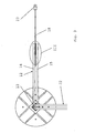
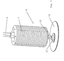
- the Fig. 5 to 7 show a modified embodiment in which the air gap 20 is arranged in a plane, on which the pendulum 6 is perpendicular in a state of rest. Same elements as in the Fig. 1 to 4 are provided with the same reference numerals.
- the circuit board 18 is supported here by a support plate 24.
- the support plate 24 may be formed of steel, for example, whereby a positive influence on the magnetic field is achieved.
- the magnet assembly 12 has a plurality of permanent magnets 16 which are arranged in a plurality of circular rings, here five circular rings. Each annulus is divided into several segments, in this case in eighteen segments. Conveniently, the permanent magnets 16 are always arranged with alternating orientation, so that in a circular ring in the direction of rotation of the annulus always has a permanent magnet with a north pole and the next permanent magnet with a south pole to the conductor assembly 18.
- the permanent magnets in the radial direction are also arranged with alternating polarity, so that a permanent magnet, which is directed with a north pole to the conductor assembly 18, in the radial direction, a permanent magnet follows, which is directed with a south pole to the conductor assembly 18, then again a permanent magnet follows, which is directed with a north pole to the conductor assembly 18.
- the pendulum hinge 13 allows not only an angular change between the pendulum 6 and the magnet assembly 12, but also a certain height offset between the pendulum 6 and the magnet assembly, ie a movement substantially perpendicular to the movement of the pendulum 6.
- the slide assembly 19 defines the distance between the magnet assembly 12 and the conductor assembly 18, so that upon movement of the pendulum 6, the magnet assembly 12 is practically displaced only on the conductor assembly 18.
- the air gap 20 between the magnet assembly 12 and the conductor assembly 18 can thus be kept constant over the entire deflection of the pendulum 6.
- both damper arrangements work in principle in the same way.
- the magnetic field generating device which by the assemblies 12, 22 ( Fig. 2 to 4 ) or the magnet assembly 12 (FIG. Fig. 5 to 7 ) is moved relative to the conductor assembly 18 moves.
- a magnetic field is accordingly moved relative to a conductor, so that eddy currents are induced in the conductor. Since the conductor assembly 18 has no discrete tracks, the eddy currents in this conductor assembly 18 can form freely, regardless of the exact position of the pendulum 6 relative to the conductor assembly 18.
- the energy required to form the eddy currents is removed from the kinetic energy of the pendulum 6 and leads to it to the desired damping.
- a largely temperature-independent damping force can be set.
- a good linearity is obtained, i. a velocity-proportional damping force, regardless of the position or deflection of the pendulum 6.
- the components of the damping assembly 8 operate virtually wear-free, i. The cost of maintenance can be kept extremely small.
- the dimensions of the magnet assemblies 12, 22 or the magnet assembly 12 may be varied. As long as it is ensured that even with the largest deflection of the pendulum 6 there is an overlap between the magnetic field generating device and the conductor arrangement 18, the magnetic assemblies 12, 22 can be enlarged virtually as desired. Another adjustment results from the choice of the material for the conductor arrangement and by the choice of the geometric dimensions, in particular the thickness of the conductor arrangement and the air gap.
- the heat generated by the eddy currents can be dissipated via the surface of the conductor assembly 18 easily.
Landscapes
- Engineering & Computer Science (AREA)
- General Engineering & Computer Science (AREA)
- Mechanical Engineering (AREA)
- Sustainable Energy (AREA)
- Chemical & Material Sciences (AREA)
- Combustion & Propulsion (AREA)
- Life Sciences & Earth Sciences (AREA)
- Sustainable Development (AREA)
- Physics & Mathematics (AREA)
- Electromagnetism (AREA)
- Acoustics & Sound (AREA)
- Aviation & Aerospace Engineering (AREA)
- Vibration Prevention Devices (AREA)
Description
- Die Erfindung betrifft eine Schwingungstilgeranordnung für hohe schlanke Bauwerke, mit einem Pendel, das am Bauwerk aufhängbar ist und eine Tilgermasse aufweist, und einer Dämpferanordnung.
- Eine derartige Tilgeranordnung ist aus
WO 2009/068599 A2 bekannt. Hier ist eine Windturbine mit einem Stahlturm dargestellt, in dem ein Pendel mit einer Tilgermasse aufgehängt ist. Das Pendel wirkt mit einer Dämpferanordnung zusammen, die durch eine Reihe von aufeinander liegenden Platten gebildet ist. Die Platten weisen jeweils eine mittige Öffnung auf, durch die das Pendel ragt. Wenn das Pendel schwingt, dann werden die Platten relativ zueinander verschoben. Durch diese Relativverschiebungen der Platten zueinander entsteht Reibung, die der Schwingungsbewegung Energie entzieht. - Eine weitere Tilgeranordnung der eingangs genannten Art ist aus
DE 198 56 500 B4 bekannt. Hier ist das Pendel über ein Lager im Turm einer Windturbine aufgehängt, das Elastomer-Bauteile umfasst. Bei einer Schwingung des Pendels werden die Elastomer-Bauteile verformt, wodurch infolge der Materialdämpfung des Elastomer-Materials der Schwingungsbewegung Energie entzogen wird. - Die Erfindung wird im Folgenden anhand eines Turms für eine Windenergieanlage beschrieben. Sie ist aber auch bei anderen hohen und schlanken Bauwerken anwendbar, z.B. bei Schornsteinen, Antennen, Hochhäusern, Türmen oder Offshore-Bauwerken wie Transformator-Stationen. Unter einem "hohen, schlanken Bauwerk" soll ein Bauwerk verstanden werden, das ein Verhältnis zwischen Höhe und kleinster Breite von mindestens 5 aufweist.
- In Windenergieanlagen ist der Durchmesser der Rotoren in den letzten Jahren stetig gewachsen. In gleicher Weise muss die Höhe der Türme der Windenergieanlagen wachsen, weil in größeren Höhen bessere Windverhältnisse herrschen und weil die Rotorblätter einen bestimmten Sicherheitsabstand zum Boden aufweisen müssen. Aus Gründen der Materialkosten ist man jedoch bestrebt, die Türme möglichst schlank zu halten.
- Der Turm einer Windenergieanlage wird zu Schwingungen angeregt, insbesondere durch Windkräfte, aber auch durch Betriebskräfte und bei Windenergieanlagen im Meer zusätzlich durch Wellenkräfte. Dabei verbiegt sich der Turm, was auf Dauer zu kritischen Zuständen führen kann. Relevant sind im Wesentlichen die beiden ersten Biege-Eigenformen des Turms samt Gondel und Rotor.
- Eine Maßnahme zur Erhöhung der Dämpfung und damit zur Verminderung der Schwingungen des Turms ist die Verwendung von Schwingungstilgern. Um die Funktionsfähigkeit von derartigen Tilgern zu gewährleisten, müssen die einzelnen Parameter des Schwingungstilgers aufeinander und auf den jeweiligen Turm abgestimmt werden. Schwierig ist vor allem die Darstellung der Tilgerdämpfung. Die eingangs genannten Lösungen verwenden hierfür Reibungsdämpfung (
WO 2009/068599 A2 ) bzw. Elastomerdämpfung (DE 198 56 500 B4 ), ferner sind in der Technik für Tilger allgemein Flüssigkeitsdämpfungen bekannt, d.h. Dämpfung, bei der von der Viskosität von Flüssigkeiten Gebrauch gemacht wird. -
US 2007/131504 A1 zeigt einen Dämpfer zur Verringerung von Vibrationen einer mechanischen Struktur innerhalb einer ausgewählten Ebene. Die Dämpferanordnung ist dabei mit einem Rahmen an einer zu dämpfenden Struktur angebracht. Die Dämpferanordnung ist weiterhin als Wirbelstromdämpfer ausgebildet und umfasst eine leitfähige Platte sowie eine Magnetanordnung. Die leitfähige Platte oder die Magnetanordnung ist dabei über flexible Elemente mit dem Rahmen verbunden. Somit kann die leitfähige Platte relativ zur Magnetanordnung bewegt werden um zur Dämpfung Wirbelströme zu erzeugen. -
DE 37 41 578 A1 zeigt eine weitere Vibrationsdämpfungsvorrichtung umfassend ein erstes Bauteil und ein zweites Bauteil die über eine Federvorrichtung miteinander verbunden sind. Am ersten Bauteil ist dabei eine Magnetanordnung befestigt, während am zweiten Bauteil eine Leiteranordnung befestigt ist. Wird die Dämpfungsvorrichtung nun durch eine Vibration in Schwingungen versetzt, so bewegt sich die Leiteranordnung relativ zur Magnetanordnung wodurch Wirbelströme erzeugt werden und eine Dämpfung der Schwingung erfolgt. -
JP 1 108431 A - Die in einem Tilger verwendeten Dämpfungselemente müssen hohen Anforderungen bezüglich Temperaturunabhängigkeit, Linearität, Alterung, Verschleiß und Leistungsaufnahmefähigkeit genügen.
- Der Erfindung liegt die Aufgabe zugrunde, eine Tilgeranordnung anzugeben, die verschleißarm und alterungsbeständig ist und eine geringere Temperaturabhängigkeit aufweist.
- Diese Aufgabe wird bei einer Tilgeranordnung der eingangs genannten Art dadurch gelöst, dass die Dämpferanordnung als Wirbelstromdämpfer ausgebildet ist, wobei der Wirbelstromdämpfer zwei Elemente aufweist, von denen eines als Magnetfelderzeugungseinrichtung und eines als Leiteranordnung ausgebildet ist, wobei eines der Elemente durch eine Bewegung des Pendels relativ zum anderen bewegbar ist, und wobei zwischen den beiden Elementen eine Gleitanordnung angeordnet ist.
- Bei einem Dämpfer wird Bewegungsenergie irreversibel in eine andere Energieform umgesetzt. Diese andere Energieform ist in den meisten Fällen Wärme. Ein Wirbelstromdämpfer verwendet zur Umsetzung der Bewegungsenergie elektrische Ströme, die durch ein Magnetfeld induziert werden, das bei einer Bewegung des Pendels gegenüber einem anderen Element bewegt wird. Diese Wirbelströme erzeugen dann Wärme. Die dadurch der Schwingungsbewegung entzogene Energie führt zur Dämpfung der Schwingung. Der Wirbelstromdämpfer hat darüber hinaus den Vorteil, dass seine Dämpfungswirkung abhängig von der Bewegungsgeschwindigkeit des Pendels ist. Bis zu einer Grenzgeschwindigkeit kann die Dämpfungskraft als linear, d.h. als proportional zur Geschwindigkeit angenommen werden. Die Frequenz der Schwingung ist dafür von untergeordneter Bedeutung. Weiterhin weist der Wirbelstromdämpfer zwei Elemente auf, von denen eines als Magnetfelderzeugungseinrichtung und eines als Leiteranordnung ausgebildet ist, wobei eines der Elemente durch eine Bewegung des Pendels relativ zum anderen bewegbar ist. Mit dieser Ausgestaltung wird erreicht, dass ein Magnetfeld, das durch die Magnetfelderzeugungseinrichtung erzeugt wird, gegenüber einer Leiteranordnung bewegt werden kann. Beispielsweise kann die Magnetfelderzeugungseinrichtung am Pendel angeordnet sein. Wenn die Magnetfelderzeugungseinrichtung gegenüber der Leiteranordnung bewegt wird, dann induziert sie in der Leiteranordnung die oben genannten Wirbelströme. Die zur Erzeugung der Wirbelströme notwendige Energie wird der Bewegung des Pendels entzogen. Außerdem ist zwischen den beiden Elementen Magnetfeldanordnung und Leiteranordnung eine Gleitanordnung angeordnet. Die Gleitanordnung hält eine Reibung und damit möglichen Verschleiß klein. Darüber hinaus kann sie für einen konstanten Abstand zwischen den beiden Elementen sorgen und damit für einen gleichförmigen Luftspalt.
- Vorzugsweise weist die Leiteranordnung eine elektrisch leitfähige Platte auf, die parallel zur Richtung der Bewegung angeordnet ist. Man kann auf einzelne Leiterbahnen verzichten. Diese sind auch nicht erforderlich, weil die Wirbelströme nicht weiter verwendet werden, sondern der Erzeugung von Verlustleistung dienen, um der Bewegung des Pendels Energie zu entziehen. Durch die Verwendung einer elektrisch leitfähigen Platte ist sichergestellt, dass die Wirbelströme in jeder Position der Magnetfelderzeugungseinrichtung relativ zur Leiteranordnung gleichartig erzeugt werden können.
- Hierbei ist bevorzugt, dass die Platte aus Aluminium oder Kupfer oder einer Legierung aus Aluminium und Kupfer oder einem anderen Material mit hoher elektrischer Leitfähigkeit gebildet ist. Die genannten Materialien haben eine ausreichende elektrische Leitfähigkeit, so dass entsprechend große Wirbelströme induziert werden können.
- Vorzugsweise ist die Leiteranordnung von einer magnetischen Trägerplatte unterstützt. Die Trägerplatte sorgt für eine vorteilhafte Ausrichtung der magnetischen Feldlinien und für eine erhöhte mechanische Steifigkeit. Sie kann eine geringere elektrische Leitfähigkeit als die Leiteranordnung aufweisen. Beispielsweise kann sie als Stahlplatte ausgebildet sein. Sie sorgt dafür, dass die Leiteranordnung formstabil ist, so dass die Magnetfeldanordnung und die Leiteranordnung immer mit einem relativ geringen Luftspalt relativ zueinander bewegt werden können.
- Vorzugsweise ist eines der Elemente über eine Pendel-Gelenkverbindung mit dem Pendel verbunden. Wenn das Pendel schwingt, dann wird es aus der Schwerkraftrichtung ausgelenkt. Die Pendel-Gelenkverbindung sorgt dafür, dass trotz dieser Auslenkung die beiden Elemente parallel zueinander bleiben können oder eine Winkeländerung zwischen den beiden Elementen jedenfalls nicht zu groß wird.
- Vorzugsweise erlaubt die Pendel-Gelenkverbindung eine Bewegung zwischen dem Pendel und dem Element senkrecht zur Richtung der Bewegung. In diesem Fall kann man dafür sorgen, dass trotz der Auslenkung des Pendels die Dicke des Luftspalts nicht geändert wird, so dass auch bei einer größeren Auslenkung des Pendels ein Luftspalt aufrecht erhalten bleibt, der eine minimale Dicke aufweist. Je kleiner der Luftspalt ist, desto besser ist die Wirkung der Magnetfelderzeugungseinrichtung zur Erzeugung der Wirbelströme.
- Vorzugsweise ist das andere der Elemente über eine Bauwerks-Gelenkverbindung mit dem Bauwerk verbindbar. In diesem Fall kann auch das andere Element eine Bewegung ausführen, die der Auslenkung des Pendels aus der Schwerkraftrichtung heraus folgen kann, so dass der Luftspalt in einem verbesserten Maße klein gehalten werden kann.
- Vorzugsweise sind die beiden Elemente über eine Parallelführung miteinander gekoppelt. Die Parallelführung sorgt dafür, dass die beiden Elemente immer parallel zueinander bewegt werden, so dass der Luftspalt immer auf einer konstanten, kleinen Dicke gehalten werden kann. Wenn der Luftspalt konstant gehalten werden kann, dann ist die Erzeugung der Wirbelströme unabhängig von der Auslenkung des Pendels, also über die gesamte Schwingung des Pendels, gleich.
- Vorzugsweise ist eines der Elemente mit zwei Teilen ausgebildet und das andere Element ist zwischen den beiden Teilen angeordnet. So kann man beispielsweise die Magnetfelderzeugungseinrichtung zweiteilig ausbilden und die Leiteranordnung zwischen den beiden Teilen anordnen. Es ist auch möglich, die Leiteranordnung zweiteilig auszubilden und die Magnetfelderzeugungseinrichtung zwischen den beiden Teilen der Leiteranordnung anzuordnen. Die beiden Elemente führen sich dann gegenseitig, so dass der Luftspalt zwischen der Leiteranordnung und der Magnetfelderzeugungseinrichtung immer in der eingestellten Dicke beibehalten werden kann.
- Vorzugsweise ist zwischen den beiden Elementen ein Luftspalt ausgebildet, der parallel zu einer Ebene angeordnet ist, in der sich das Pendel in einem Ruhezustand befindet. Im Ruhezustand hängt das Pendel senkrecht. Die Ebene, in der der Luftspalt angeordnet ist, steht dann ebenfalls senkrecht. Wenn man eine zweidimensionale Bewegung des Pendels ermöglichen möchte, dann kann man entweder dafür sorgen, dass der Luftspalt gedreht werden kann, so dass die Dämpfungswirkung immer der Bewegung des Pendels folgt, oder man kann die Magnetfelderzeugungseinrichtung und die Leiteranordnung auch in mehrere Teile aufteilen, die dann beispielsweise unter einem Winkel von 90° zueinander angeordnet sind, so dass unabhängig von der Bewegungsrichtung des Pendels immer eine Magnetfelderzeugungseinrichtung und eine Leiteranordnung relativ zueinander bewegt werden.
- In einer alternativen Ausgestaltung kann vorgesehen sein, dass zwischen den beiden Elementen ein Luftspalt ausgebildet ist, der parallel zu einer Ebene angeordnet ist, auf der das Pendel im Ruhezustand senkrecht steht. Diese Ebene liegt dann horizontal. Auch dies ist eine relativ einfache Möglichkeit, eine Dämpfung unabhängig von der Bewegungsrichtung des Pendels zu erzielen.
- Vorzugsweise ist der Wirbelstromdämpfer am in Schwerkraftrichtung unteren Ende des Pendels angeordnet. Am unteren Ende des Pendels ergibt sich die größte Bewegung des Pendels, so dass hier auch die größte Dämpfung erzielt werden kann.
- Vorteilhafterweise ist die Tilgermasse höhenverstellbar am Pendel angeordnet. Durch die Verstellbarkeit der Tilgermasse ist es möglich, auch bei einer montierten Schwingungstilgeranordnung Einfluss auf die Frequenz zu nehmen, auf die das Pendel abgestimmt ist. Damit kann man der Tatsache Rechnung tragen, dass hohe und schlanke Bauwerke vielfach in geringem Umfang von der geplanten Konstruktion abweichen, wodurch sich ihre Eigenfrequenz verändert.
- Auch ist von Vorteil, wenn das Pendel mit einer Federanordnung verbunden ist, die zwischen dem Pendel und dem Bauwerk positionierbar ist. Eine derartige Federanordnung wirkt dann in Bewegungsrichtung der Tilgermasse. Die Federanordnung dient zur Erhöhung der Tilgersteifigkeit.
- Die Erfindung betrifft sowohl die Verwendung von den oben beschriebenen Wirbelstromdämpfern in Verbindung mit rein passiven Schwingungstilgern als auch deren Verwendung in Verbindung mit semiaktiven und aktiven Schwingungstilgern, d.h. bei Schwingungstilgern, bei denen entweder die passiven Parameter, bevorzugt Steifigkeit bzw. Tilgereigenfrequenz und Dämpfung, mit Hilfe von Sensoren und Aktoren eingestellt werden können (semiaktiver Schwingungstilger) oder aber bei denen die schwingungsmindernden Kräfte selbst mit Hilfe von Sensoren und Aktoren erzeugt werden (aktive Schwingungstilger).
- Die Erfindung betrifft auch ein Bauwerk mit einer Schwingungstilgeranordnung wie sie oben beschrieben worden ist.
- Die Erfindung wird im Folgenden anhand von bevorzugten Ausführungsbeispielen in Verbindung mit der Zeichnung beschrieben. Hierin zeigen:
- Fig. 1
- eine stark schematisierte Darstellung einer Windenergieanlage,
- Fig. 2
- eine erste Ausgestaltung einer Tilgermasse mit einer Dämpferanordnung,
- Fig. 3
- die Ausgestaltung nach
Fig. 2 von unten, - Fig. 4
- eine Einzelheit III nach
Fig. 3 , - Fig. 5
- eine zweite Ausgestaltung einer Tilgermasse mit einer Dämpferanordnung,
- Fig. 6
- eine vergrößerte Darstellung der Dämpferanordnung und
- Fig. 7
- die Dämpferanordnung von unten.
-
Fig. 1 zeigt schematisch eine Windenergieanlage 1 mit einem Turm 2. Der Turm hat beispielsweise eine Höhe von 100 m und einen Durchmesser von 4 m. Am oberen Ende des Turmes 2 ist eine Gondel 3 angeordnet, die einen Rotor 4 trägt. Wenn der Rotor 4 sich dreht, treibt er einen in der Gondel 3 angeordneten Generator an. - Im Turm 2 ist eine Tilgeranordnung 5 vorgesehen. Die Tilgeranordnung weist ein Pendel 6 auf, das am Turm 2 aufgehängt ist. Das Pendel 6 weist eine Tilgermasse 7 auf. Unterhalb der Tilgermasse 7 ist eine Dämpferanordnung 8 angeordnet, die als Wirbelstromdämpfer ausgebildet ist.
- Optional weist die Tilgeranordnung eine Verstelleinrichtung 9 auf, mit der die Tilgermasse 7 entlang des Pendels 6 verschoben werden kann. Dies dient der Einstellung der Tilgereigenfrequenz im Falle einer Ausführung als semiaktiver Tilger.
- Optional weist die Tilgeranordnung zusätzliche Federelemente 10 auf, mit Hilfe derer die Steifigkeit des Tilgers erhöht werden kann. Dadurch kann der Tilger auf höhere Tilgereigenfrequenzen eingestellt werden, die alleine durch Reduktion der effektiven Länge des Pendels 6 nicht eingestellt werden können.
- Optional weist die Tilgeranordnung einen Aktor 11 auf, wodurch die Anwendung als aktiver Tilger ermöglicht wird.
- Der Turm 2 ist als Stahlturm ausgebildet, d.h. er weist eine Wand auf, die aus mehreren Stahlsegmenten zusammengesetzt ist. Die einzelnen Stahlsegmente haben die Form eines Kreiszylinders, der sich leicht nach oben hin verjüngt.
- Die hier dargestellte Tilgeranordnung 5 dient im Wesentlichen zum Dämpfen der ersten Eigenfrequenz des Turms. Wenn die Dämpfung einer anderen Eigenfrequenz des Turms gewünscht ist, dann muss das Pendel 6 unter Umständen an einer anderen Position mit dem Turm 2 verbunden werden.
- Die
Fig. 2 bis 4 zeigen eine erste Ausgestaltung der Tilgeranordnung im Ausschnitt. - Die Tilgermasse 7 ist am unteren Ende des Pendels 6 aufgehängt. Das Pendel 6 ist hier als Pendelstab ausgebildet.
- Die Dämpferanordnung 8 weist hier eine erste Magnetbaugruppe 12 auf, die über eine Pendel-Gelenkverbindung 13 mit der Tilgermasse 7 und damit mit dem Pendel 6 verbunden ist. Die erste Magnetbaugruppe 12 weist zwei Träger 14, 15 auf, von denen jeder eine Reihe von Permanentmagneten 16, 17 trägt. In jeder Reihe von Permanentmagneten 16, 17 sind Permanentmagnete mit abwechselnd unterschiedlich ausgerichteten Polarisierungen angeordnet. Zwischen den Permanentmagneten 16, 17 ist eine Leiteranordnung 18 angeordnet, die im vorliegenden Fall als Platte aus Aluminium oder Kuper oder einer Legierung aus Aluminium und Kupfer gebildet ist. Die Permanentmagnete 16, 17 sind so zueinander angeordnet, dass das durch sie erzeugte Magnetfeld durch die Leiteranordnung 18 hindurch tritt. Die Leiteranordnung ist unmagnetisch und schirmt das Magnetfeld nicht ab. Zwischen den Permanentmagneten 16, 17 und der Leiteranordnung 18 ist eine Gleitanordnung 19 vorgesehen. Die Gleitanordnung 19 erlaubt ein reibungsarmes Gleiten der Leiteranordnung 18 zwischen den Permanentmagneten 16, 17, so dass ein Verschleiß klein gehalten werden kann. Darüber hinaus erlaubt die Gleitanordnung 19, einen Luftspalt 20, 21 zwischen der Leiteranordnung 18 und den Permanentmagneten 16, 17 auf eine außerordentlich kleine Dicke einzustellen. Je kleiner der Luftspalt ist, desto besser ist die Wirkung der Permanentmagneten 16, 17 bei der Erzeugung von Wirbelströmen in der Leiteranordnung 18. Diese Wirbelströme 18 werden induziert, wenn sich die Permanentmagnete 16, 17 relativ zu der Leiteranordnung 18 bewegen.
- Eine zweite Magnetbaugruppe 22 ist ebenfalls über die Pendel-Gelenkverbindung 13 mit dem Pendel 6 verbunden. Die zweite Magnetbaugruppe 22 ist im Ruhezustand des Pendels 6, also wenn das Pendel 6 senkrecht hängt, etwa senkrecht zur ersten Magnetbaugruppe 12 ausgerichtet. Die Pendel-Gelenkverbindung erlaubt eine gewisse Beweglichkeit der beiden Magnetbaugruppen 12, 22 relativ zu dem Pendel 6.
- Im Übrigen gilt die Beschreibung der ersten Magnetbaugruppe 12 in entsprechender Weise für die zweite Magnetbaugruppe 22, d.h. die zweite Magnetbaugruppe 22 weist ebenfalls Permanentmagnete auf, zwischen denen eine Leiteranordnung angeordnet ist.
- Die Leiteranordnung 18 ist über eine Bauwerks-Gelenkverbindung 23 mit dem Turm verbunden, so dass die Leiteranordnung 18 in gewissen Bereichen auch der Schwingungsbewegung des Pendels 6 folgen kann.
- Die Träger 14, 15 bilden gemeinsam mit der Gleitanordnung 19 eine Parallelführung für die Leiteranordnung 18, so dass man über die gesamte Schwingungsbewegung des Pendels 6 einen konstanten Luftspalt aufrechterhalten kann. Dementsprechend ergeben sich über den gesamten Schwingungsbereich des Pendels 6 die gleichen Verhältnisse bei der Erzeugung der Wirbelströme. Somit ist die Dämpfungswirkung über den gesamten Schwingungsbereich gleich.
- Selbstverständlich ist es möglich, anstelle von Permanentmagneten auch Elektromagnete zu verwenden. Bei Permanentmagneten wird ein Magnetfeld durch die Permanentmagnete erzeugt. Bei Elektromagneten ist zur Erzeugung des Magnetfeldes eine elektrische Energiezufuhr erforderlich.
- Selbstverständlich ist es auch möglich, die Leiteranordnung 18 mit dem Pendel 6 und die Magnetbaugruppen 12, 22 mit dem Turm 2 zu verbinden.
- Die beiden Magnetbaugruppen 12, 22 bilden zusammen die Magnetfelderzeugungseinrichtung.
- Bei der Ausgestaltung nach den
Fig. 2 bis 4 ist der Luftspalt 20, 21, der zwischen den Permanentmagneten 16, 17 und der Leiteranordnung 18 ausgebildet ist, in einer Ebene angeordnet, die parallel zu einer Ebene angeordnet ist, in der sich das Pendel in einem Ruhezustand befindet. - Die
Fig. 5 bis 7 zeigen eine abgewandelte Ausgestaltung, bei der der Luftspalt 20 in einer Ebene angeordnet ist, auf der das Pendel 6 in einem Ruhezustand senkrecht steht. Gleiche Elemente wie in denFig. 1 bis 4 sind mit den gleichen Bezugszeichen versehen. - Die Leiterplatte 18 ist hier von einer Trägerplatte 24 unterstützt. Die Trägerplatte 24 kann beispielsweise aus Stahl gebildet sein, wodurch eine positive Beeinflussung des magnetischen Feldes erreicht wird.
- Zwischen der Magnetbaugruppe 12 und der Leiteranordnung 18 ist wiederum eine Gleitanordnung 19 vorgesehen, die als ringförmiger Gleitbelag zwischen der Magnetbaugruppe 12 und der Leiteranordnung 18 ausgebildet ist. Wie man aus
Fig. 7 erkennen kann, weist die Magnetbaugruppe 12 eine Vielzahl von Permanentmagneten 16 auf, die in mehreren Kreisringen, hier fünf Kreisringen, angeordnet sind. Jeder Kreisring ist in mehrere Segmente unterteilt, im vorliegenden Fall in achtzehn Segmente. Zweckmäßigerweise sind die Permanentmagnete 16 immer mit abwechselnder Orientierung angeordnet, so dass in einem Kreisring in Umlaufrichtung des Kreisrings immer ein Permanentmagnet mit einem Nordpol und der nächste Permanentmagnet mit einem Südpol zur Leiteranordnung 18 weist. In jedem Segment sind die Permanentmagnete in radialer Richtung ebenfalls mit abwechselnder Polarität angeordnet, so dass auf einen Permanentmagneten, der mit einem Nordpol zur Leiteranordnung 18 gerichtet ist, in Radialrichtung ein Permanentmagnet folgt, der mit einem Südpol zur Leiteranordnung 18 gerichtet ist, wobei dann wieder ein Permanentmagnet folgt, der mit einem Nordpol zur Leiteranordnung 18 gerichtet ist. - Die Pendel-Gelenkverbindung 13 erlaubt nicht nur eine Winkeländerung zwischen dem Pendel 6 und der Magnetbaugruppe 12, sondern auch einen gewissen Höhenversatz zwischen dem Pendel 6 und der Magnetbaugruppe, also eine Bewegung im Wesentlichen senkrecht zur Bewegung des Pendels 6. Die Gleitanordnung 19 definiert den Abstand zwischen der Magnetbaugruppe 12 und der Leiteranordnung 18, so dass bei einer Bewegung des Pendels 6 die Magnetbaugruppe 12 praktisch nur auf der Leiteranordnung 18 verschoben wird. Der Luftspalt 20 zwischen der Magnetbaugruppe 12 und der Leiteranordnung 18 kann also über die gesamte Auslenkung des Pendels 6 konstant gehalten werden.
- Beide Dämpferanordnungen arbeiten im Prinzip auf die gleiche Weise. Bei einer Bewegung des Pendels 6 wird die Magnetfelderzeugungseinrichtung, die durch die Baugruppen 12, 22 (
Fig. 2 bis 4 ) oder die Magnetbaugruppe 12 (Fig. 5 bis 7 ) gebildet ist, relativ zur Leiteranordnung 18 bewegt. Bei der Bewegung wird dementsprechend ein Magnetfeld relativ zu einem Leiter bewegt, so dass in dem Leiter Wirbelströme induziert werden. Da die Leiteranordnung 18 keine diskreten Leiterbahnen aufweist, können sich die Wirbelströme in dieser Leiteranordnung 18 frei ausbilden, unabhängig von der genauen Position des Pendels 6 relativ zur Leiteranordnung 18. Die zur Ausbildung der Wirbelströme erforderliche Energie wird der Bewegungsenergie des Pendels 6 entzogen und führt damit zu der gewünschten Dämpfung. - Mit beiden Ausgestaltungen lässt sich eine weitgehend temperaturunabhängige Dämpfungskraft einstellen. Man erhält eine gute Linearität, d.h. eine geschwindigkeitsproportionale Dämpfungskraft, unabhängig von der Position oder Auslenkung des Pendels 6. Beim Beginn einer Schwingungsbewegung muss man keine Losbrechkräfte oder Stick-Slip-Effekte überwinden. Die Komponenten der Dämpfungsanordnung 8 arbeiten praktisch verschleißfrei, d.h. der Aufwand für Wartung kann außerordentlich klein gehalten werden.
- Man kann die Dämpferanordnung 8 relativ leicht an unterschiedliche Gegebenheiten anpassen. So kann man beispielsweise die Abmessungen der Magnetbaugruppen 12, 22 oder der Magnetbaugruppe 12 variieren. Solange sichergestellt ist, dass auch bei der größten Auslenkung des Pendels 6 eine Überdeckung zwischen der Magnetfelderzeugungseinrichtung und der Leiteranordnung 18 besteht, kann man die Magnetbaugruppen 12, 22 praktisch beliebig vergrößern. Eine weitere Einstellmöglichkeit ergibt sich durch die Wahl des Werkstoffs für die Leiteranordnung und durch die Wahl der geometrischen Abmessungen, insbesondere der Dicke der Leiteranordnung und des Luftspalts.
- Die durch die Wirbelströme erzeugte Wärme kann über die Oberfläche der Leiteranordnung 18 problemlos abgeführt werden.
Claims (15)
- Schwingungstilgeranordnung zur Verminderung von Schwingungen für hohe schlanke Bauwerke (2), mit einem Pendel (6), das am Bauwerk (2) aufhängbar ist und eine Tilgermasse (7) aufweist, und einer Dämpferanordnung (8), dadurch gekennzeichnet, dass die Dämpferanordnung (8) als Wirbelstromdämpfer ausgebildet ist, wobei der Wirbelstromdämpfer zwei Elemente aufweist, von denen eines als Magnetfelderzeugungseinrichtung (12, 22) und eines als Leiteranordnung (18) ausgebildet ist, wobei eines der Elemente durch eine Bewegung des Pendels (6) relativ zum anderen bewegbar ist, und zwischen den beiden Elementen eine Gleitanordnung (19) angeordnet ist.
- Schwingungstilgeranordnung nach Anspruch 1, dadurch gekennzeichnet, dass die Leiteranordnung eine leitfähige Platte aufweist, die parallel zur Richtung der Bewegung des Pendels (6) angeordnet ist.
- Schwingungstilgeranordnung nach Anspruch 2, dadurch gekennzeichnet, dass die Platte aus Aluminium oder Kupfer oder einer Legierung aus Aluminium und Kupfer oder aus einem anderen Material mit hoher elektrischer Leitfähigkeit gebildet ist.
- Schwingungstilgeranordnung nach einem der Ansprüche 1 bis 3, dadurch gekennzeichnet, dass die Leiteranordnung (18) von einer Trägerplatte (24) unterstützt ist.
- Schwingungstilgeranordnung nach einem der Ansprüche 1 bis 4, dadurch gekennzeichnet, dass eines der Elemente über eine Pendel - Gelenkverbindung (13) mit dem Pendel (6) verbunden ist.
- Schwingungstilgeranordnung nach Anspruch 5, dadurch gekennzeichnet, dass die Pendel - Gelenkverbindung (13) eine Bewegung zwischen dem Pendel (6) und dem Element senkrecht zur Richtung der Bewegung des Pendels (6) erlaubt.
- Schwingungstilgeranordnung nach Anspruch 5 oder 6, dadurch gekennzeichnet, dass das andere der Elemente über eine Bauwerks-Gelenkverbindung (23) mit dem Bauwerk (2) verbindbar ist.
- Schwingungstilgeranordnung nach einem der Ansprüche 5 bis 7, dadurch gekennzeichnet, dass die beiden Elemente über eine Parallelführung miteinander gekoppelt sind.
- Schwingungstilgeranordnung nach Anspruch 7, dadurch gekennzeichnet, dass eines der Elemente mit zwei Teilen (14, 15) ausgebildet ist und das andere Element zwischen den beiden Teilen (14, 15) angeordnet ist.
- Schwingungstilgeranordnung nach einem der Ansprüche 1 bis 9, dadurch gekennzeichnet, dass zwischen den beiden Elementen ein Luftspalt (20, 21) ausgebildet ist, der parallel zu einer Ebene angeordnet ist, in der sich das Pendel (6) in einem Ruhezustand befindet.
- Schwingungstilgeranordnung nach einem der Ansprüche 1 bis 9, dadurch gekennzeichnet, dass zwischen den beiden Elementen ein Luftspalt (20) ausgebildet ist, der parallel zu einer Ebene angeordnet ist, auf der das Pendel (6) im Ruhezustand senkrecht steht.
- Schwingungstilgeranordnung nach einem der Ansprüche 1 bis 11, dadurch gekennzeichnet, dass der Wirbelstromdämpfer am in Schwerkraftrichtung unteren Ende des Pendels (6) angeordnet ist.
- Schwingungstilgeranordnung nach einem der Ansprüche 1 bis 12, dadurch gekennzeichnet, dass die Tilgermasse (7) höhenverstellbar am Pendel (6) angeordnet ist.
- Schwingungstilgeranordnung nach einem der Ansprüche 1 bis 13, dadurch gekennzeichnet, dass das Pendel (6) mit einer Federanordnung (10) verbunden ist, die zwischen dem Pendel (6) und dem Bauwerk (2) positionierbar ist.
- Bauwerk (2) mit einer Schwingungstilgeranordnung nach einem der Ansprüche 1 bis 12.
Priority Applications (2)
| Application Number | Priority Date | Filing Date | Title |
|---|---|---|---|
| DK12005805.2T DK2696072T3 (en) | 2012-08-10 | 2012-08-10 | Vibration absorber for wind power plants with a lot of pendulum and hvirvelstrømsdæmper |
| EP12005805.2A EP2696072B1 (de) | 2012-08-10 | 2012-08-10 | Schwingungstilgeranordnung für Windkraftanlagen mit Massenpendel und Wirbelstromdämpfer |
Applications Claiming Priority (1)
| Application Number | Priority Date | Filing Date | Title |
|---|---|---|---|
| EP12005805.2A EP2696072B1 (de) | 2012-08-10 | 2012-08-10 | Schwingungstilgeranordnung für Windkraftanlagen mit Massenpendel und Wirbelstromdämpfer |
Publications (2)
| Publication Number | Publication Date |
|---|---|
| EP2696072A1 EP2696072A1 (de) | 2014-02-12 |
| EP2696072B1 true EP2696072B1 (de) | 2015-03-25 |
Family
ID=46967894
Family Applications (1)
| Application Number | Title | Priority Date | Filing Date |
|---|---|---|---|
| EP12005805.2A Active EP2696072B1 (de) | 2012-08-10 | 2012-08-10 | Schwingungstilgeranordnung für Windkraftanlagen mit Massenpendel und Wirbelstromdämpfer |
Country Status (2)
| Country | Link |
|---|---|
| EP (1) | EP2696072B1 (de) |
| DK (1) | DK2696072T3 (de) |
Cited By (3)
| Publication number | Priority date | Publication date | Assignee | Title |
|---|---|---|---|---|
| CN111164326A (zh) * | 2017-08-08 | 2020-05-15 | Fm能源有限责任两合公司 | 旋转阻尼器和装备有旋转阻尼器的振动减振器 |
| EP3441609B1 (de) * | 2017-08-09 | 2023-05-10 | General Electric Company | Dämpfungsvorrichtung für onshore- und offshore-windenergieanlagen |
| US12607246B2 (en) | 2021-03-31 | 2026-04-21 | Fm Energie Gmbh & Co.Kg | Temperature-adaptive eddy current rotation damper |
Families Citing this family (10)
| Publication number | Priority date | Publication date | Assignee | Title |
|---|---|---|---|---|
| ES2705054T3 (es) | 2014-08-13 | 2019-03-21 | Esm Energie Und Schwingungstechnik Mitsch Gmbh | Amortiguador magnético para absorbedores de vibraciones |
| EP3388709B1 (de) * | 2017-04-13 | 2021-01-06 | Wölfel Engineering GmbH & Co. KG. | Schwingungsdämpferanordnung |
| WO2019185196A1 (de) | 2018-03-30 | 2019-10-03 | Esm Energie- Und Schwingungstechnik Mitsch Gmbh | Lineare magnetfeder und verwendung in schwingungstilgern |
| CN112219043B (zh) | 2018-04-18 | 2022-12-27 | Fm能源有限责任两合公司 | 用于摆式减振器的阻尼万向悬挂 |
| EP3575630B1 (de) * | 2018-05-29 | 2021-05-12 | Wölfel Engineering GmbH + Co. KG | Schwingungsdämpferanordnung |
| EP3814628B1 (de) | 2018-06-29 | 2023-08-02 | Vestas Wind Systems A/S | Dämpfereinheit für eine turmkonstruktion |
| US11293512B2 (en) * | 2018-10-18 | 2022-04-05 | Dalian University Of Technology | Multi-dimensional eddy current tuned mass damper |
| CN113464384A (zh) * | 2020-03-31 | 2021-10-01 | 北京金风科创风电设备有限公司 | 阻尼装置及风力发电机组 |
| EP4086459A1 (de) | 2021-05-06 | 2022-11-09 | General Electric Renovables España S.L. | Windturbine mit eigenfrequenzmodifikator |
| CN115405648B (zh) * | 2022-08-03 | 2025-04-29 | 上海电气风电集团股份有限公司 | 单摆式减振装置及风力发电机组 |
Citations (5)
| Publication number | Priority date | Publication date | Assignee | Title |
|---|---|---|---|---|
| SU853034A2 (ru) | 1979-05-10 | 1981-08-07 | Харьковское Отделение Всесоюзногогосударственного Ордена Ленина Иордена Октябрьской Революциипроектного Института "Теплоэлектро-Проект" | Динамический гаситель колебанийСООРужЕНи |
| EP0767321A2 (de) | 1995-10-02 | 1997-04-09 | Kabushiki Kaisha Toshiba | Dynamischer Schwingungsdämpfer |
| WO2009068599A2 (en) | 2007-11-28 | 2009-06-04 | Vestas Wind Systems A/S | Method for damping oscillations in a wind turbine |
| CN202091424U (zh) | 2011-06-13 | 2011-12-28 | 马人乐 | 风力发电塔钟式减振器 |
| WO2012061859A2 (de) | 2010-11-10 | 2012-05-18 | Alois Penz | Turmartiges, hohles bauwerk, insbesondere aufwindkamin |
Family Cites Families (4)
| Publication number | Priority date | Publication date | Assignee | Title |
|---|---|---|---|---|
| JPS63149446A (ja) * | 1986-12-11 | 1988-06-22 | Bridgestone Corp | 防振装置 |
| JPH01108431A (ja) * | 1987-10-22 | 1989-04-25 | Toshiba Corp | 磁気ダンパ装置 |
| DE19856500B4 (de) | 1998-12-08 | 2005-12-08 | Franz Mitsch | Schwingungstilger |
| US20070131504A1 (en) * | 2005-12-14 | 2007-06-14 | Northrop Grumman Corporation | Planar vibration absorber |
-
2012
- 2012-08-10 EP EP12005805.2A patent/EP2696072B1/de active Active
- 2012-08-10 DK DK12005805.2T patent/DK2696072T3/en active
Patent Citations (5)
| Publication number | Priority date | Publication date | Assignee | Title |
|---|---|---|---|---|
| SU853034A2 (ru) | 1979-05-10 | 1981-08-07 | Харьковское Отделение Всесоюзногогосударственного Ордена Ленина Иордена Октябрьской Революциипроектного Института "Теплоэлектро-Проект" | Динамический гаситель колебанийСООРужЕНи |
| EP0767321A2 (de) | 1995-10-02 | 1997-04-09 | Kabushiki Kaisha Toshiba | Dynamischer Schwingungsdämpfer |
| WO2009068599A2 (en) | 2007-11-28 | 2009-06-04 | Vestas Wind Systems A/S | Method for damping oscillations in a wind turbine |
| WO2012061859A2 (de) | 2010-11-10 | 2012-05-18 | Alois Penz | Turmartiges, hohles bauwerk, insbesondere aufwindkamin |
| CN202091424U (zh) | 2011-06-13 | 2011-12-28 | 马人乐 | 风力发电塔钟式减振器 |
Non-Patent Citations (7)
| Title |
|---|
| CHRISTIAN PETERSEN: "Dynamik der Baukonstruktionen", 1996, VIEWEG, ISBN: 3-528-08123-6, article "Schwingungsdämpfer", pages: 821-850, 1003 - 1011, XP055316331 |
| EBRAHIMI ET AL.: "Design and modeling of a magnetic shock absorber base on eddy current damping effect", JOURNAL OF SOUND AND VIBRATION, vol. 315, 2008, pages 875 - 889, XP022705855 |
| KOBAYASHI ET AL.: "Houde Damper Using Magnet Damping and its Application to the Piping system", SEISMIC ENGINEERING, vol. 2, 1994, pages 105 - 109, XP055316418 |
| R. PALOMERA-ARIAS ET AL.: "Feasibility Study of Passive Electromagnetic Damping Systems", JOURNAL OF STRUCTURAL ENGINEERING, ASCE, vol. 134, no. 1, January 2008 (2008-01-01), pages 164 - 170, XP055316420 |
| TAICHI MATSUOKA ET AL.: "A Study of a Magnetic Damper Using Rare-Earth Magnets and a Pinned Displacement Magnifying Mechanism", INTERNATIONAL JOURNAL OF APPLIED ELECTROMAGNETICS AND MECHANICS, vol. 13, no. 1-4, 2001, pages 261 - 270, XP055316410 |
| VEREIN DEUTSCHER INGENIEURE (VDI): "VDI Richtlinie 3833 Blatt 2 - Schwingungsdämpfer und Schwingungstilger", VDI-RICHTLINIEN, December 2006 (2006-12-01), pages 1 - 36, XP055316440 |
| ZUO ET AL.: "Design and Analysis of a New Type of Electromagnetic Damper With increased Energy Density", JOURNAL OF VIBRATION AND ACOUSTICS, vol. 133, August 2011 (2011-08-01), pages 041006-1 - 041006-8, XP055316426 |
Cited By (4)
| Publication number | Priority date | Publication date | Assignee | Title |
|---|---|---|---|---|
| CN111164326A (zh) * | 2017-08-08 | 2020-05-15 | Fm能源有限责任两合公司 | 旋转阻尼器和装备有旋转阻尼器的振动减振器 |
| CN111164326B (zh) * | 2017-08-08 | 2022-02-22 | Fm能源有限责任两合公司 | 旋转阻尼器和装备有旋转阻尼器的振动减振器 |
| EP3441609B1 (de) * | 2017-08-09 | 2023-05-10 | General Electric Company | Dämpfungsvorrichtung für onshore- und offshore-windenergieanlagen |
| US12607246B2 (en) | 2021-03-31 | 2026-04-21 | Fm Energie Gmbh & Co.Kg | Temperature-adaptive eddy current rotation damper |
Also Published As
| Publication number | Publication date |
|---|---|
| EP2696072A1 (de) | 2014-02-12 |
| DK2696072T3 (en) | 2015-06-08 |
Similar Documents
| Publication | Publication Date | Title |
|---|---|---|
| EP2696072A1 (de) | Schwingungstilgeranordnung für Windkraftanlagen mit Massenpendel und Wirbelstromdämpfer | |
| EP2746483B1 (de) | Schwingungstilgeranordnurg | |
| EP3610172B1 (de) | Schwingungsdämpfung eines windenergieanlagenturms | |
| EP3665398B1 (de) | Schwingungstilger mit rotationsdämpfer | |
| EP1008747B1 (de) | Schwingungstilger für Windkraftanlagen | |
| EP3227579B1 (de) | Adaptiver pendeltilger mit vertikaler federvorrichtung | |
| EP2929098B1 (de) | Schwingungsbegrenzungs-modul sowie vorrichtung, bausegment für eine baueinrichtung und windenergieanlage mit einem schwingungsbegrenzungs-modul | |
| WO2019201471A1 (de) | Dämpfende kardanaufhängung für pendeltilger | |
| DE102008042478A1 (de) | Verfahren zur Schwingungstilgung und horizontal wirkender Schwingungstilger | |
| DE102006022266A1 (de) | Windenergieanlage | |
| EP3433509B1 (de) | Kompaktes räumliches ellipsoid-massenpendel | |
| DE102007041128B4 (de) | Schwinggenerator | |
| EP2522850A2 (de) | Turmschwingungstilger und Turm mit einem Turmschwingungstilger | |
| DE202011001901U1 (de) | Vorrichtung zur Schwingungsanregung von Rotorblättern im Rahmen von Schwingungstests | |
| WO2022135755A1 (de) | Bauwerksdämpfer zum schutz von bauwerken gegen schwingungen und bauwerk mit einem solchen bauwerksdämpfer | |
| WO2019185196A1 (de) | Lineare magnetfeder und verwendung in schwingungstilgern | |
| EP2730709B1 (de) | Schwingungstilgeranordnung | |
| DE19715714A1 (de) | Dämpferelement und damit versehene Dämpfungseinheit | |
| EP3575630B1 (de) | Schwingungsdämpferanordnung | |
| EP2730799B1 (de) | Schwingungstilgeranordnung zur verminderung von schwingungen | |
| EP2715248A2 (de) | Vorrichtungen zur optimierung und betriebsstabilisierung einzelner solarer module/kollektormodule und zusammengesetzter kollektormodulgruppen gegen umwelteinflüsse, insbesondere wind und mit dem wind mitbewegte partikel und gegenstände | |
| DE102016202632A1 (de) | Vorrichtung zur Umwandlung von mechanischer in elektrische Energie und entsprechendes Verfahren | |
| DE102022101726A1 (de) | Windkraftanlage | |
| EP3922879A1 (de) | Tilgeranordnung | |
| WO2026052602A1 (de) | Schwingungstilgeranordnung für hohe schlanke bauwerke |
Legal Events
| Date | Code | Title | Description |
|---|---|---|---|
| AK | Designated contracting states |
Kind code of ref document: A1 Designated state(s): AL AT BE BG CH CY CZ DE DK EE ES FI FR GB GR HR HU IE IS IT LI LT LU LV MC MK MT NL NO PL PT RO RS SE SI SK SM TR |
|
| AX | Request for extension of the european patent |
Extension state: BA ME |
|
| PUAI | Public reference made under article 153(3) epc to a published international application that has entered the european phase |
Free format text: ORIGINAL CODE: 0009012 |
|
| 17P | Request for examination filed |
Effective date: 20140116 |
|
| RBV | Designated contracting states (corrected) |
Designated state(s): AL AT BE BG CH CY CZ DE DK EE ES FI FR GB GR HR HU IE IS IT LI LT LU LV MC MK MT NL NO PL PT RO RS SE SI SK SM TR |
|
| GRAP | Despatch of communication of intention to grant a patent |
Free format text: ORIGINAL CODE: EPIDOSNIGR1 |
|
| RIC1 | Information provided on ipc code assigned before grant |
Ipc: F03D 11/04 20060101ALI20141007BHEP Ipc: F03D 11/00 20060101AFI20141007BHEP Ipc: F16F 15/03 20060101ALI20141007BHEP |
|
| INTG | Intention to grant announced |
Effective date: 20141103 |
|
| GRAS | Grant fee paid |
Free format text: ORIGINAL CODE: EPIDOSNIGR3 |
|
| GRAA | (expected) grant |
Free format text: ORIGINAL CODE: 0009210 |
|
| AK | Designated contracting states |
Kind code of ref document: B1 Designated state(s): AL AT BE BG CH CY CZ DE DK EE ES FI FR GB GR HR HU IE IS IT LI LT LU LV MC MK MT NL NO PL PT RO RS SE SI SK SM TR |
|
| REG | Reference to a national code |
Ref country code: GB Ref legal event code: FG4D Free format text: NOT ENGLISH |
|
| REG | Reference to a national code |
Ref country code: CH Ref legal event code: EP |
|
| REG | Reference to a national code |
Ref country code: IE Ref legal event code: FG4D Free format text: LANGUAGE OF EP DOCUMENT: GERMAN |
|
| REG | Reference to a national code |
Ref country code: DE Ref legal event code: R096 Ref document number: 502012002610 Country of ref document: DE Effective date: 20150507 |
|
| REG | Reference to a national code |
Ref country code: AT Ref legal event code: REF Ref document number: 718053 Country of ref document: AT Kind code of ref document: T Effective date: 20150515 |
|
| REG | Reference to a national code |
Ref country code: DK Ref legal event code: T3 Effective date: 20150604 |
|
| REG | Reference to a national code |
Ref country code: SE Ref legal event code: TRGR |
|
| PG25 | Lapsed in a contracting state [announced via postgrant information from national office to epo] |
Ref country code: FI Free format text: LAPSE BECAUSE OF FAILURE TO SUBMIT A TRANSLATION OF THE DESCRIPTION OR TO PAY THE FEE WITHIN THE PRESCRIBED TIME-LIMIT Effective date: 20150325 Ref country code: LT Free format text: LAPSE BECAUSE OF FAILURE TO SUBMIT A TRANSLATION OF THE DESCRIPTION OR TO PAY THE FEE WITHIN THE PRESCRIBED TIME-LIMIT Effective date: 20150325 Ref country code: HR Free format text: LAPSE BECAUSE OF FAILURE TO SUBMIT A TRANSLATION OF THE DESCRIPTION OR TO PAY THE FEE WITHIN THE PRESCRIBED TIME-LIMIT Effective date: 20150325 |
|
| REG | Reference to a national code |
Ref country code: FR Ref legal event code: PLFP Year of fee payment: 4 |
|
| REG | Reference to a national code |
Ref country code: LT Ref legal event code: MG4D |
|
| PG25 | Lapsed in a contracting state [announced via postgrant information from national office to epo] |
Ref country code: LV Free format text: LAPSE BECAUSE OF FAILURE TO SUBMIT A TRANSLATION OF THE DESCRIPTION OR TO PAY THE FEE WITHIN THE PRESCRIBED TIME-LIMIT Effective date: 20150325 Ref country code: GR Free format text: LAPSE BECAUSE OF FAILURE TO SUBMIT A TRANSLATION OF THE DESCRIPTION OR TO PAY THE FEE WITHIN THE PRESCRIBED TIME-LIMIT Effective date: 20150626 Ref country code: RS Free format text: LAPSE BECAUSE OF FAILURE TO SUBMIT A TRANSLATION OF THE DESCRIPTION OR TO PAY THE FEE WITHIN THE PRESCRIBED TIME-LIMIT Effective date: 20150325 |
|
| PG25 | Lapsed in a contracting state [announced via postgrant information from national office to epo] |
Ref country code: NL Free format text: LAPSE BECAUSE OF FAILURE TO SUBMIT A TRANSLATION OF THE DESCRIPTION OR TO PAY THE FEE WITHIN THE PRESCRIBED TIME-LIMIT Effective date: 20150325 |
|
| PG25 | Lapsed in a contracting state [announced via postgrant information from national office to epo] |
Ref country code: CZ Free format text: LAPSE BECAUSE OF FAILURE TO SUBMIT A TRANSLATION OF THE DESCRIPTION OR TO PAY THE FEE WITHIN THE PRESCRIBED TIME-LIMIT Effective date: 20150325 Ref country code: SK Free format text: LAPSE BECAUSE OF FAILURE TO SUBMIT A TRANSLATION OF THE DESCRIPTION OR TO PAY THE FEE WITHIN THE PRESCRIBED TIME-LIMIT Effective date: 20150325 Ref country code: RO Free format text: LAPSE BECAUSE OF FAILURE TO SUBMIT A TRANSLATION OF THE DESCRIPTION OR TO PAY THE FEE WITHIN THE PRESCRIBED TIME-LIMIT Effective date: 20150325 Ref country code: ES Free format text: LAPSE BECAUSE OF FAILURE TO SUBMIT A TRANSLATION OF THE DESCRIPTION OR TO PAY THE FEE WITHIN THE PRESCRIBED TIME-LIMIT Effective date: 20150325 Ref country code: EE Free format text: LAPSE BECAUSE OF FAILURE TO SUBMIT A TRANSLATION OF THE DESCRIPTION OR TO PAY THE FEE WITHIN THE PRESCRIBED TIME-LIMIT Effective date: 20150325 Ref country code: PT Free format text: LAPSE BECAUSE OF FAILURE TO SUBMIT A TRANSLATION OF THE DESCRIPTION OR TO PAY THE FEE WITHIN THE PRESCRIBED TIME-LIMIT Effective date: 20150727 |
|
| PG25 | Lapsed in a contracting state [announced via postgrant information from national office to epo] |
Ref country code: PL Free format text: LAPSE BECAUSE OF FAILURE TO SUBMIT A TRANSLATION OF THE DESCRIPTION OR TO PAY THE FEE WITHIN THE PRESCRIBED TIME-LIMIT Effective date: 20150325 Ref country code: IS Free format text: LAPSE BECAUSE OF FAILURE TO SUBMIT A TRANSLATION OF THE DESCRIPTION OR TO PAY THE FEE WITHIN THE PRESCRIBED TIME-LIMIT Effective date: 20150725 |
|
| REG | Reference to a national code |
Ref country code: DE Ref legal event code: R026 Ref document number: 502012002610 Country of ref document: DE |
|
| PLBI | Opposition filed |
Free format text: ORIGINAL CODE: 0009260 |
|
| PLBI | Opposition filed |
Free format text: ORIGINAL CODE: 0009260 |
|
| 26 | Opposition filed |
Opponent name: ESM ENERGIE- UND SCHWINGUNGSTECHNIK MITSCH GMBH Effective date: 20151219 |
|
| PLAX | Notice of opposition and request to file observation + time limit sent |
Free format text: ORIGINAL CODE: EPIDOSNOBS2 |
|
| 26 | Opposition filed |
Opponent name: SIEMENS AKTIENGESELLSCHAFT Effective date: 20151223 |
|
| PG25 | Lapsed in a contracting state [announced via postgrant information from national office to epo] |
Ref country code: MC Free format text: LAPSE BECAUSE OF FAILURE TO SUBMIT A TRANSLATION OF THE DESCRIPTION OR TO PAY THE FEE WITHIN THE PRESCRIBED TIME-LIMIT Effective date: 20150325 Ref country code: LU Free format text: LAPSE BECAUSE OF FAILURE TO SUBMIT A TRANSLATION OF THE DESCRIPTION OR TO PAY THE FEE WITHIN THE PRESCRIBED TIME-LIMIT Effective date: 20150810 |
|
| REG | Reference to a national code |
Ref country code: CH Ref legal event code: PL |
|
| PG25 | Lapsed in a contracting state [announced via postgrant information from national office to epo] |
Ref country code: CH Free format text: LAPSE BECAUSE OF NON-PAYMENT OF DUE FEES Effective date: 20150831 Ref country code: LI Free format text: LAPSE BECAUSE OF NON-PAYMENT OF DUE FEES Effective date: 20150831 Ref country code: IT Free format text: LAPSE BECAUSE OF FAILURE TO SUBMIT A TRANSLATION OF THE DESCRIPTION OR TO PAY THE FEE WITHIN THE PRESCRIBED TIME-LIMIT Effective date: 20150325 |
|
| PG25 | Lapsed in a contracting state [announced via postgrant information from national office to epo] |
Ref country code: SI Free format text: LAPSE BECAUSE OF FAILURE TO SUBMIT A TRANSLATION OF THE DESCRIPTION OR TO PAY THE FEE WITHIN THE PRESCRIBED TIME-LIMIT Effective date: 20150325 |
|
| REG | Reference to a national code |
Ref country code: IE Ref legal event code: MM4A |
|
| PLAF | Information modified related to communication of a notice of opposition and request to file observations + time limit |
Free format text: ORIGINAL CODE: EPIDOSCOBS2 |
|
| PG25 | Lapsed in a contracting state [announced via postgrant information from national office to epo] |
Ref country code: IE Free format text: LAPSE BECAUSE OF NON-PAYMENT OF DUE FEES Effective date: 20150810 |
|
| PLBB | Reply of patent proprietor to notice(s) of opposition received |
Free format text: ORIGINAL CODE: EPIDOSNOBS3 |
|
| REG | Reference to a national code |
Ref country code: FR Ref legal event code: PLFP Year of fee payment: 5 |
|
| PG25 | Lapsed in a contracting state [announced via postgrant information from national office to epo] |
Ref country code: MT Free format text: LAPSE BECAUSE OF FAILURE TO SUBMIT A TRANSLATION OF THE DESCRIPTION OR TO PAY THE FEE WITHIN THE PRESCRIBED TIME-LIMIT Effective date: 20150325 |
|
| PG25 | Lapsed in a contracting state [announced via postgrant information from national office to epo] |
Ref country code: SM Free format text: LAPSE BECAUSE OF FAILURE TO SUBMIT A TRANSLATION OF THE DESCRIPTION OR TO PAY THE FEE WITHIN THE PRESCRIBED TIME-LIMIT Effective date: 20150325 Ref country code: NO Free format text: LAPSE BECAUSE OF FAILURE TO SUBMIT A TRANSLATION OF THE DESCRIPTION OR TO PAY THE FEE WITHIN THE PRESCRIBED TIME-LIMIT Effective date: 20150625 Ref country code: HU Free format text: LAPSE BECAUSE OF FAILURE TO SUBMIT A TRANSLATION OF THE DESCRIPTION OR TO PAY THE FEE WITHIN THE PRESCRIBED TIME-LIMIT; INVALID AB INITIO Effective date: 20120810 Ref country code: BG Free format text: LAPSE BECAUSE OF FAILURE TO SUBMIT A TRANSLATION OF THE DESCRIPTION OR TO PAY THE FEE WITHIN THE PRESCRIBED TIME-LIMIT Effective date: 20150325 |
|
| PG25 | Lapsed in a contracting state [announced via postgrant information from national office to epo] |
Ref country code: CY Free format text: LAPSE BECAUSE OF FAILURE TO SUBMIT A TRANSLATION OF THE DESCRIPTION OR TO PAY THE FEE WITHIN THE PRESCRIBED TIME-LIMIT Effective date: 20150325 |
|
| PG25 | Lapsed in a contracting state [announced via postgrant information from national office to epo] |
Ref country code: BE Free format text: LAPSE BECAUSE OF NON-PAYMENT OF DUE FEES Effective date: 20150831 |
|
| REG | Reference to a national code |
Ref country code: FR Ref legal event code: PLFP Year of fee payment: 6 |
|
| PLBP | Opposition withdrawn |
Free format text: ORIGINAL CODE: 0009264 |
|
| REG | Reference to a national code |
Ref country code: DE Ref legal event code: R100 Ref document number: 502012002610 Country of ref document: DE |
|
| PLBP | Opposition withdrawn |
Free format text: ORIGINAL CODE: 0009264 |
|
| PLCK | Communication despatched that opposition was rejected |
Free format text: ORIGINAL CODE: EPIDOSNREJ1 |
|
| PLAB | Opposition data, opponent's data or that of the opponent's representative modified |
Free format text: ORIGINAL CODE: 0009299OPPO |
|
| PLBN | Opposition rejected |
Free format text: ORIGINAL CODE: 0009273 |
|
| STAA | Information on the status of an ep patent application or granted ep patent |
Free format text: STATUS: OPPOSITION REJECTED |
|
| 27O | Opposition rejected |
Effective date: 20170913 |
|
| PG25 | Lapsed in a contracting state [announced via postgrant information from national office to epo] |
Ref country code: MK Free format text: LAPSE BECAUSE OF FAILURE TO SUBMIT A TRANSLATION OF THE DESCRIPTION OR TO PAY THE FEE WITHIN THE PRESCRIBED TIME-LIMIT Effective date: 20150325 Ref country code: TR Free format text: LAPSE BECAUSE OF FAILURE TO SUBMIT A TRANSLATION OF THE DESCRIPTION OR TO PAY THE FEE WITHIN THE PRESCRIBED TIME-LIMIT Effective date: 20150325 |
|
| REG | Reference to a national code |
Ref country code: FR Ref legal event code: PLFP Year of fee payment: 7 |
|
| REG | Reference to a national code |
Ref country code: AT Ref legal event code: MM01 Ref document number: 718053 Country of ref document: AT Kind code of ref document: T Effective date: 20170810 |
|
| REG | Reference to a national code |
Ref country code: DE Ref legal event code: R082 Ref document number: 502012002610 Country of ref document: DE Representative=s name: KEIL & SCHAAFHAUSEN PATENTANWAELTE PARTGMBB, DE Ref country code: DE Ref legal event code: R082 Ref document number: 502012002610 Country of ref document: DE Representative=s name: KEIL & SCHAAFHAUSEN PATENT- UND RECHTSANWAELTE, DE |
|
| PG25 | Lapsed in a contracting state [announced via postgrant information from national office to epo] |
Ref country code: AL Free format text: LAPSE BECAUSE OF FAILURE TO SUBMIT A TRANSLATION OF THE DESCRIPTION OR TO PAY THE FEE WITHIN THE PRESCRIBED TIME-LIMIT Effective date: 20150325 |
|
| PG25 | Lapsed in a contracting state [announced via postgrant information from national office to epo] |
Ref country code: AT Free format text: LAPSE BECAUSE OF NON-PAYMENT OF DUE FEES Effective date: 20170810 |
|
| P01 | Opt-out of the competence of the unified patent court (upc) registered |
Effective date: 20230524 |
|
| PGFP | Annual fee paid to national office [announced via postgrant information from national office to epo] |
Ref country code: DK Payment date: 20250821 Year of fee payment: 14 Ref country code: DE Payment date: 20250822 Year of fee payment: 14 |
|
| PGFP | Annual fee paid to national office [announced via postgrant information from national office to epo] |
Ref country code: GB Payment date: 20250822 Year of fee payment: 14 |
|
| PGFP | Annual fee paid to national office [announced via postgrant information from national office to epo] |
Ref country code: FR Payment date: 20250821 Year of fee payment: 14 |
|
| PGFP | Annual fee paid to national office [announced via postgrant information from national office to epo] |
Ref country code: SE Payment date: 20250821 Year of fee payment: 14 |