EP2695662A1 - Co2 recovery device and operation control method of co2 recovery device - Google Patents
Co2 recovery device and operation control method of co2 recovery device Download PDFInfo
- Publication number
- EP2695662A1 EP2695662A1 EP11859860.6A EP11859860A EP2695662A1 EP 2695662 A1 EP2695662 A1 EP 2695662A1 EP 11859860 A EP11859860 A EP 11859860A EP 2695662 A1 EP2695662 A1 EP 2695662A1
- Authority
- EP
- European Patent Office
- Prior art keywords
- exhaust gas
- absorbing solution
- absorber
- supply amount
- amount
- Prior art date
- Legal status (The legal status is an assumption and is not a legal conclusion. Google has not performed a legal analysis and makes no representation as to the accuracy of the status listed.)
- Granted
Links
Images



Classifications
-
- B—PERFORMING OPERATIONS; TRANSPORTING
- B01—PHYSICAL OR CHEMICAL PROCESSES OR APPARATUS IN GENERAL
- B01D—SEPARATION
- B01D53/00—Separation of gases or vapours; Recovering vapours of volatile solvents from gases; Chemical or biological purification of waste gases, e.g. engine exhaust gases, smoke, fumes, flue gases, aerosols
- B01D53/14—Separation of gases or vapours; Recovering vapours of volatile solvents from gases; Chemical or biological purification of waste gases, e.g. engine exhaust gases, smoke, fumes, flue gases, aerosols by absorption
- B01D53/1412—Controlling the absorption process
-
- B—PERFORMING OPERATIONS; TRANSPORTING
- B01—PHYSICAL OR CHEMICAL PROCESSES OR APPARATUS IN GENERAL
- B01D—SEPARATION
- B01D53/00—Separation of gases or vapours; Recovering vapours of volatile solvents from gases; Chemical or biological purification of waste gases, e.g. engine exhaust gases, smoke, fumes, flue gases, aerosols
- B01D53/14—Separation of gases or vapours; Recovering vapours of volatile solvents from gases; Chemical or biological purification of waste gases, e.g. engine exhaust gases, smoke, fumes, flue gases, aerosols by absorption
- B01D53/1456—Removing acid components
- B01D53/1475—Removing carbon dioxide
-
- C—CHEMISTRY; METALLURGY
- C01—INORGANIC CHEMISTRY
- C01B—NON-METALLIC ELEMENTS; COMPOUNDS THEREOF; METALLOIDS OR COMPOUNDS THEREOF NOT COVERED BY SUBCLASS C01C
- C01B32/00—Carbon; Compounds thereof
- C01B32/50—Carbon dioxide
-
- B—PERFORMING OPERATIONS; TRANSPORTING
- B01—PHYSICAL OR CHEMICAL PROCESSES OR APPARATUS IN GENERAL
- B01D—SEPARATION
- B01D2252/00—Absorbents, i.e. solvents and liquid materials for gas absorption
- B01D2252/20—Organic absorbents
- B01D2252/204—Amines
-
- B—PERFORMING OPERATIONS; TRANSPORTING
- B01—PHYSICAL OR CHEMICAL PROCESSES OR APPARATUS IN GENERAL
- B01D—SEPARATION
- B01D2257/00—Components to be removed
- B01D2257/50—Carbon oxides
- B01D2257/504—Carbon dioxide
-
- B—PERFORMING OPERATIONS; TRANSPORTING
- B01—PHYSICAL OR CHEMICAL PROCESSES OR APPARATUS IN GENERAL
- B01D—SEPARATION
- B01D2258/00—Sources of waste gases
- B01D2258/02—Other waste gases
- B01D2258/0283—Flue gases
-
- B—PERFORMING OPERATIONS; TRANSPORTING
- B01—PHYSICAL OR CHEMICAL PROCESSES OR APPARATUS IN GENERAL
- B01D—SEPARATION
- B01D53/00—Separation of gases or vapours; Recovering vapours of volatile solvents from gases; Chemical or biological purification of waste gases, e.g. engine exhaust gases, smoke, fumes, flue gases, aerosols
- B01D53/34—Chemical or biological purification of waste gases
- B01D53/46—Removing components of defined structure
- B01D53/62—Carbon oxides
-
- Y—GENERAL TAGGING OF NEW TECHNOLOGICAL DEVELOPMENTS; GENERAL TAGGING OF CROSS-SECTIONAL TECHNOLOGIES SPANNING OVER SEVERAL SECTIONS OF THE IPC; TECHNICAL SUBJECTS COVERED BY FORMER USPC CROSS-REFERENCE ART COLLECTIONS [XRACs] AND DIGESTS
- Y02—TECHNOLOGIES OR APPLICATIONS FOR MITIGATION OR ADAPTATION AGAINST CLIMATE CHANGE
- Y02C—CAPTURE, STORAGE, SEQUESTRATION OR DISPOSAL OF GREENHOUSE GASES [GHG]
- Y02C20/00—Capture or disposal of greenhouse gases
- Y02C20/40—Capture or disposal of greenhouse gases of CO2
-
- Y—GENERAL TAGGING OF NEW TECHNOLOGICAL DEVELOPMENTS; GENERAL TAGGING OF CROSS-SECTIONAL TECHNOLOGIES SPANNING OVER SEVERAL SECTIONS OF THE IPC; TECHNICAL SUBJECTS COVERED BY FORMER USPC CROSS-REFERENCE ART COLLECTIONS [XRACs] AND DIGESTS
- Y02—TECHNOLOGIES OR APPLICATIONS FOR MITIGATION OR ADAPTATION AGAINST CLIMATE CHANGE
- Y02P—CLIMATE CHANGE MITIGATION TECHNOLOGIES IN THE PRODUCTION OR PROCESSING OF GOODS
- Y02P20/00—Technologies relating to chemical industry
- Y02P20/151—Reduction of greenhouse gas [GHG] emissions, e.g. CO2
Definitions
- the present invention relates to a CO 2 recovering apparatus that maintains, at a substantially constant level, the concentration of CO 2 absorbing solution of a CO 2 recovering apparatus which absorbs CO 2 in exhaust gas using CO 2 absorbing solution, and an operation control method of the CO 2 recovering apparatus.
- exhaust gas generated when the fossil fuel is burned in a boiler contains CO 2 and the like.
- As a method of eliminating and recovering CO 2 contained in exhaust gas there is a method of bringing the exhaust gas into gas-liquid contact with an amine CO 2 absorbing solution to absorb CO 2 in the CO 2 absorbing solution. Then, the CO 2 is released from the CO 2 absorbing solution having absorbed the CO 2 , and the released CO 2 is stored in the ground, thereby preventing the CO 2 recovered from the exhaust gas from being released into the atmosphere.
- the CO 2 recovering apparatus includes a CO 2 absorber that allows the exhaust gas to contact a CO 2 absorbing solution and allows the CO 2 absorbing solution to absorb CO 2 contained in the exhaust gas, and a regenerator that releases CO 2 absorbed by the CO 2 absorbing solution and separates CO 2 from the CO 2 absorbing solution.
- This CO 2 recovering apparatus causes the CO 2 absorber to absorb the CO 2 contained in the exhaust gas in the CO 2 absorbing solution and eliminates the CO 2 from the exhaust gas, and then causes the regenerator to heat the CO 2 absorbing solution with vapor, thereby releasing the CO 2 absorbed by the CO 2 absorbing solution and recovering high-purity CO 2 . Further, the CO 2 absorbing solution regenerated by the regenerator is fed to the CO 2 absorber again and is recycled.
- system space a space between the CO 2 absorber and the regenerator
- makeup water is added to the system space or the condensation amount of water contained in the exhaust gas within the CO 2 absorber is adjusted.
- the condensation amount of water contained in the exhaust gas within the CO 2 absorber is controlled by, for example, a method of adjusting the cooling ratio of the exhaust gas by using a cooling tower or the like provided at the upstream side of the absorber, or a method of adjusting the cooling temperature of the CO 2 absorbing solution within the CO 2 absorber.
- the absorber or the regenerator is provided with an absorbing solution level meter and a level controller, and the condensation amount of water contained in the exhaust gas or the supply amount of makeup water is adjusted to thereby maintain the liquid level at a constant liquid level.
- Patent Literature 1 Japanese Patent Application Laid-open No 2008-062165
- the level controller maintains, at a constant level, the flow rate of the CO 2 absorbing solution that circulates in the system space. Accordingly, the level controller operates to perform adjustment by condensing H 2 O contained in the exhaust gas by the amount corresponding to the accumulation amount of the CO 2 absorbing solution accumulated in the CO 2 recovering unit, or by increasing the supply amount of makeup water.
- the level controller increases the condensation amount of water contained in the exhaust gas or increases the supply amount of makeup water in the state where the accumulation amount of the CO 2 absorbing solution in the CO 2 recovering unit is not taken into consideration. This causes a problem that the concentration of the CO 2 absorbing solution in the system space is lowered. Accordingly, the CO 2 absorption performance of the CO 2 contained in the exhaust gas in the CO 2 absorber is lowered.
- the present invention has been made in view of the above-mentioned circumstances, and therefore an object of the present invention is to provide a CO 2 recovering apparatus capable of stably maintaining the concentration of CO 2 absorbing solution at a constant level.
- a CO 2 recovering apparatus including: a cooling tower that allows an exhaust gas containing CO 2 to contact water and cools the exhaust gas; a CO 2 absorber that allows the exhaust gas to contact a CO 2 absorbing solution that absorbs CO 2 and eliminates CO 2 from the exhaust gas; an absorbing solution regenerator that releases CO 2 from the CO 2 absorbing solution having absorbed CO 2 and regenerates the CO 2 absorbing solution; an absorbing solution level meter that measures a liquid level of the CO 2 absorbing solution at a tower bottom of the CO 2 absorber; and a level controller that performs one of automatic control and manual control for one or both of a supply amount of makeup water to be supplied to the CO 2 absorber and a condensation amount of water contained in the exhaust gas, based on the liquid level of the CO 2 absorbing solution detected by the absorbing solution level meter, wherein while a gas supply amount of the exhaust gas to be supplied to the CO 2 absorber is not changed, the level controller is switched to the
- the CO 2 recovering apparatus according to the first aspect, wherein each measured value with the liquid level of the CO 2 absorbing solution at the tower bottom of the CO 2 absorber, the supply amount of the makeup water, the accumulation amount of the CO 2 absorbing solution, and the gas supply amount of the exhaust gas at the time when a change in the gas supply amount of the exhaust gas supplied to the CO 2 absorber is constant and the level controller is switched from the manual control to the automatic control is changed to a set value as a reference for each value.
- a CO 2 recovering apparatus including: a cooling tower that allows an exhaust gas containing CO 2 to contact water and cools the exhaust gas; a CO 2 absorber including a CO 2 recovering unit that allows a CO 2 absorbing solution that absorbs CO 2 to contact the exhaust gas, and eliminates CO 2 from the exhaust gas; an absorbing solution regenerator that releases CO 2 from the CO 2 absorbing solution having absorbed CO 2 and regenerates the CO 2 absorbing solution; an absorbing solution level meter that measures a liquid level of the CO 2 absorbing solution at a tower bottom of the CO 2 absorber; and a level controller that performs one of automatic control and manual control for one or both of a supply amount of makeup water to be supplied to the CO 2 absorber and a condensation amount of water contained in the exhaust gas, based on the liquid level of the CO 2 absorbing solution detected by the absorbing solution level meter, wherein while a gas supply amount of the exhaust gas to be supplied to the CO 2 absorber is changed, one of the gas supply amount of
- the CO 2 recovering apparatus according to any one of the first to third aspects, wherein the condensation amount of water contained in the exhaust gas is adjusted using one or both of a method of changing, by the cooling tower, a cooling ratio of the exhaust gas, and a method of changing a cooling temperature of the CO 2 absorbing solution within the CO 2 absorber.
- the CO 2 recovering apparatus according to any one of the first to fourth aspects, further including: an absorbing solution extraction pipe that extracts the CO 2 absorbing solution at the bottom of the CO 2 absorber; an absorbing solution storage unit that stores the extracted CO 2 absorbing solution; and an absorbing solution feed pipe that feeds the CO 2 absorbing solution within the absorbing solution storage unit to the bottom of the CO 2 absorber, wherein the liquid level of the CO 2 absorbing solution at the bottom of the CO 2 absorber is adjusted according to a loading state of the apparatus that generates the exhaust gas.
- an operation control method of a CO 2 recovering apparatus including a CO 2 absorber including a CO 2 recovering unit that brings an exhaust gas containing CO 2 into contact with water to cool the exhaust gas and brings the exhaust gas into contact with a CO 2 absorbing solution absorbing CO 2 to eliminate CO 2 contained the exhaust gas; and a regenerator that eliminates CO 2 contained in the CO 2 absorbing solution having absorbed CO 2 to regenerate the CO 2 absorbing solution
- the operation control method including: recycling, by the CO 2 absorber, the CO 2 absorbing solution obtained by eliminating CO 2 by the regenerator; measuring, by an absorbing solution level meter, a liquid level of the CO 2 absorbing solution at a tower bottom of the CO 2 absorber; and performing, by a level controller, one of automatic control and manual control for one or both of a supply amount of makeup water to be supplied to the CO 2 absorber and a condensation amount of water contained in the exhaust gas, based on the liquid level of the CO 2 absorbing solution detected by the absorbing solution level meter
- a seventh aspect of the present invention there is provided the operation control method of a CO 2 recovering apparatus according to the sixth aspect, wherein each measured value with the liquid level of the CO 2 absorbing solution at the tower bottom of the CO 2 absorber, the supply amount of the makeup water, the accumulation amount of the CO 2 absorbing solution, and the gas supply amount of the exhaust gas at the time when a change in the gas supply amount of the exhaust gas supplied to the CO 2 absorber is constant and the level controller is switched from the manual control to the automatic control is changed to a set value as a reference for each value.
- an operation control method of a CO 2 recovering apparatus including a CO 2 absorber including a CO 2 recovering unit that brings an exhaust gas containing CO 2 into contact with water to cool the exhaust gas and brings the exhaust gas into contact with a CO 2 absorbing solution to eliminate CO 2 contained in the exhaust gas; and a regenerator that eliminates CO 2 contained in the CO 2 absorbing solution having absorbed CO 2 to regenerate the CO 2 absorbing solution
- the operation control method including: recycling, by the CO 2 absorber, the CO 2 absorbing solution obtained by eliminating CO 2 by the regenerator; measuring, by an absorbing solution level meter, a liquid level of the CO 2 absorbing solution at a tower bottom of the CO 2 absorber; and performing, by a level controller, one of automatic control and manual control for one or both of a supply amount of makeup water to be supplied to the CO 2 absorber and a condensation amount of water contained in the exhaust gas, based on the liquid level of the CO 2 absorbing solution detected by the absorbing solution level meter; and wherein
- the operation control method of a CO 2 recovering apparatus according to any one of the sixth to eighth aspects, wherein the condensation amount of water contained in the exhaust gas is adjusted by using one or both of a method of changing a cooling ratio of the exhaust gas by the cooling tower, and a method of changing a cooling temperature of the CO 2 absorbing solution within the CO 2 absorber.
- the operation control method of a CO 2 recovering apparatus according to any one of the sixth to ninth aspects, further including: extracting the CO 2 absorbing solution at the bottom of the CO 2 absorber depending on a loading state of the apparatus that generates the exhaust gas; storing the extracted CO 2 absorbing solution, or feeding the stored CO 2 absorbing solution to the bottom of the CO 2 absorber; and adjusting a liquid amount of the CO 2 absorbing solution at the bottom of the CO 2 absorber.
- the concentration of a CO 2 absorbing solution can be stably maintained at a constant level. This allows the absorption amount of CO 2 contained in an exhaust gas to the CO 2 absorbing solution to be stably maintained. Furthermore, the CO 2 absorbing solution can be efficiently used without wasting amine contained in the CO 2 absorbing solution. Accordingly, the steam required for releasing the CO 2 contained in the CO 2 absorbing solution can be efficiently utilized by the regenerator, which results in improvement in operational efficiency of the CO 2 recovering apparatus.
- FIG. 1 is a diagram schematically illustrating the configuration of the CO 2 recovering apparatus according to the first embodiment of the present invention.
- a CO 2 recovering apparatus 10A includes a cooling tower 11, a CO 2 absorber 12, and an absorbing solution regenerator (hereinafter referred to as "regenerator") 13.
- a CO 2 absorbing solution 16 that absorbs CO 2 in an exhaust gas 15A containing CO 2 circulates in a space between the CO 2 absorber 12 and the regenerator 13 (hereinafter referred to as "system space").
- a CO 2 absorbing solution (rich solution) 17 having absorbed CO 2 in an exhaust gas 15B is fed to the regenerator 13 from the CO 2 absorber 12.
- the CO 2 absorbing solution (lean solution) 16 regenerated by eliminating almost all CO 2 from the rich solution 17 by the regenerator 13 is fed to the CO 2 absorber 12 from the regenerator 13.
- the exhaust gas 15A is a gas containing CO 2 discharged from industrial facilities such as a boiler and a gas turbine.
- the exhaust gas 15A is boosted by an exhaust gas blower or the like and is then sent to the cooling tower 11.
- the cooling tower 11 is a tower that cools the exhaust gas 15A with water 21.
- the cooling tower 11 includes a spray nozzle 22 that atomizes the water 21 into the tower, and a cooling unit 23.
- the cooling unit 23 in the cooling tower 11 cools the exhaust gas 15A by bringing the exhaust gas into counterflow contact with the water 21 atomized from the spray nozzle 22.
- the water 21 which is increased in temperature through heat exchange with the exhaust gas 15A is stored at the tower bottom of the cooling tower 11.
- the water 21 at the tower bottom is extracted from the tower bottom and cooled by a cooler 24 through heat exchange with chilled water 25, and is then fed to the cooling tower 11. This allows the water 21 to be circulated and used for cooling the exhaust gas 15A.
- the cooled exhaust gas 15B is discharged from the cooling tower 11 through a flue 26 which couples the cooling tower 11 and the CO 2 absorber 12.
- the exhaust gas 15B discharged from the cooling tower 11 is sent into the CO 2 absorber 12 from a side wall of tower bottom of the CO 2 absorber 12 through the flue 26.
- the CO 2 absorber 12 is a tower that allows the exhaust gas 15B and the CO 2 absorbing solution 16 to contact each other to eliminate CO 2 from the exhaust gas 15B.
- the CO 2 absorber 12 includes CO 2 recovering units 31-1 and 31-2, spray nozzles 32-1 and 32-2, a washing unit 33, and a demister 34.
- the exhaust gas 15B fed into the tower flows toward the tower top side from the tower bottom side within the tower.
- the spray nozzle 32-2 is a nozzle that atomizes the CO 2 absorbing solution 16 downwardly.
- the CO 2 recovering units 31-1 and 31-2 are provided at the front flow side in the flow direction of the exhaust gas 15B of the CO 2 absorber 12. In this embodiment, the CO 2 recovering units 31-1 and 31-2 are provided at the lower side of the tower of the CO 2 absorber 12.
- the exhaust gas 15B that ascends in the tower is brought into counterflow contact with the CO 2 absorbing solution 16 mainly including a basic amine compound, for example, and CO 2 in the exhaust gas 15B is absorbed by the CO 2 absorbing solution 16.
- the lean solution 16 is atomized from the spray nozzle 32-2 and passed through the CO 2 recovering unit 31-2
- a semi-rich solution 35 having absorbed CO 2 remaining in the exhaust gas 15B is stored by a receiving unit 36.
- the semi-rich solution 35 stored in the receiving unit 36 is extracted from a semi-rich solution extraction pipe 37 and cooled with chilled water 39 by a cooler 38. After that, the semi-rich solution 35 is atomized from the spray nozzle 32-1 and passed through the CO 2 recovering unit 31-1 and is then stored at the tower bottom as the rich solution 17.
- the CO 2 absorber 12 is provided with the two-stage CO 2 recovering unit, but this embodiment is not limited to this.
- a one-stage or three-or more-stage CO 2 recovering unit may be provided.
- the washing unit 33 and the demister 34 are provided at the backflow side in the flow direction of the exhaust gas 15B of the CO 2 absorber 12.
- the washing unit 33 and the demister 34 are provided the upper side of the CO 2 recovering unit 31-2 within the tower.
- a CO 2 removed exhaust gas 41 obtained by eliminating CO 2 by the CO 2 recovering units 31-1 and 31-2 is released to the outside of the system from the tower top after the CO 2 absorbing solution 16 accompanied with the CO 2 removed exhaust gas 41 is eliminated by the washing unit 33 and the mist contained in the CO 2 removed exhaust gas 41 is captured by the demister 34.
- a plurality of washing units 33 may be provided.
- the washing unit 33 allows a spray nozzle 43 to atomize water 42, which is externally supplied, and eliminates impurities contained in the CO 2 removed exhaust gas 41 by the washing unit 33.
- the water 42 atomized from the spray nozzle 43 is recovered by a receiving unit 44 and is fed to the outside of the tower by a pump 45. After the water 42 is cooled with chilled water 48 by a cooler 47 through a water circulation line 46, the water 42 is fed to the spray nozzle 43 and circulated and used.
- the rich solution 17 having absorbed CO 2 contained in the exhaust gas 15B in the CO 2 recovering units 31-1 and 31-2 are accumulated at the bottom of the CO 2 absorber 12.
- the rich solution 17 accumulated at the bottom of the CO 2 absorber 12 is extracted from a rich solution ejection line 51, and is pumped by a rich solution discharge pump (rich solvent pump) 52 provided outside from the tower bottom of the CO 2 absorber 12.
- a rich solution discharge pump rich solvent pump
- the regenerator 13 is a tower that releases CO 2 from the rich solution 17 and regenerates it into a lean solution 16.
- the rich solution 17 released from the tower top of the regenerator 13 into the tower of the regenerator 13 is heated by a vapor (steam) 54 supplied from the tower bottom of the regenerator 13.
- the steam 54 is generated by exchanging heat of the lean solution 16 with saturated steam 56 in a regeneration superheater (reboiler) 55.
- the heat of the rich solution 17 is absorbed by being heated by the steam 54, and most of the CO 2 contained in the rich solution 17 is released.
- the rich solution 17 reaches the tower bottom of the regenerator 13 almost all the CO 2 is eliminated to thereby obtain the CO 2 absorbing solution (lean solution) 6.
- the lean solution 16 accumulated at the bottom of the regenerator 13 is fed as a CO 2 absorbing solution by a lean solvent pump 57 and is cooled through heat exchange with chilled water 59 by a lean solvent cooler 58, and is then fed to the CO 2 absorber 12.
- a CO 2 gas 61 accompanied with vapor is released from the tower top of the regenerator 13.
- the CO 2 gas 61 accompanied with vapor is led out from the tower top of the regenerator 13, and the vapor contained in the CO 2 gas 61 is condensed with chilled water 63 by a condenser 62.
- a CO 2 gas 66 is released to the outside of the system and recovered. Further, the water 65 separated by the separation drum 64 is supplied to an upper portion of the regenerator 13 in a condensed water circulating pump 67.
- the CO 2 recovering apparatus 10A includes a supply gas flowmeter 71, an absorbing solution level meter 72, a makeup water flowmeter 73, and a thermometer 74.
- the supply gas flowmeter 71 is provided in the flue 26 and measures the flow rate of the exhaust gas 15B.
- the absorbing solution level meter 72 is provided at the tower bottom, which is a liquid pool of the CO 2 absorber 12, and measures the liquid level (liquid height) of the rich solution 17 accumulated at the tower bottom.
- the makeup water flowmeter 73 is provided to a makeup water supply line 75, and measures the flow rate of makeup water 76.
- the thermometer 74 is provided to the semi-rich solution extraction pipe 37, and measures the temperature of the semi-rich solution 35.
- the values measured by the supply gas flowmeter 71 and the absorbing solution level meter 72 are transmitted to a level controller 77.
- the level controller 77 transmits the calculated value to a manipulation unit 78 based on the value measured by the absorbing solution level meter 72, and adjusts one or both of the supply amount of the makeup water 76 and the condensation amount of water contained in the exhaust gas 15B.
- the condensation amount of water contained in the exhaust gas 15B can be adjusted using one or both of a method of increasing the cooling ratio of the exhaust gas 15B by the cooling tower 11, and a method of lowering the cooling temperature of the semi-rich solution 35 in the CO 2 absorber 12.
- the control valve V11 When the cooling ratio of the exhaust gas 15B is increased by the cooling tower 11, the control valve V11 is adjusted and the flow rate of the chilled water 25 is increased to further lower the liquid temperature of the water 21.
- the gas temperature of the exhaust gas 15B is further lowered to cool the exhaust gas 15B, water contained in the exhaust gas 15A is condensed by the cooling tower 11, so that the condensation amount of water contained in the exhaust gas 15B decreases.
- the degree of opening/closing of the control valve V12 is adjusted to further lower the liquid temperature of the semi-rich solution 35.
- the level controller 77 causes the manipulation unit 78 to adjust the control valve V11 to adjust the flow rate of the chilled water 25, causes a control unit 79 to adjust the control valve V12 to adjust the flow rate of the chilled water 39, or causes a control unit 80 to adjust a control valve V13, based on the values measured by the supply gas flowmeter 71 and the absorbing solution level meter 72, thereby adjusting the flow rate of the makeup water 76.
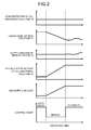
- FIG. 2 is a diagram illustrating the relationship between the operating time and various measured values when the CO 2 recovering apparatus 10A according to this embodiment is adjusted by the makeup water 76. As illustrated in FIG. 2 , while the gas supply amount of the exhaust gas 15B, which is measured by the supply gas flowmeter 71, to the CO 2 absorber 12 is not changed (the gas supply amount is constant), the measurement is carried out by the level controller 77 through the automatic control.
- the accumulation amount (liquid hold-up amount) of the CO 2 absorbing solution 16 in the CO 2 recovering unit 31-2, the supply amount of the makeup water 76, and the liquid level of the rich solution 17 accumulated at the tower bottom of the CO 2 absorber 12 are constant.
- the automatic control may adopt a continuous measurement or a periodical measurement.
- the measurement interval is not particularly limited.
- the level controller 77 is switched from the automatic control to the manual control to carry out the measurement.
- This manual control of the level controller 77 is carried out while the gas supply amount of the exhaust gas 15B to the CO 2 absorber 12.
- the gas supply amount of the exhaust gas 15B is increased, the accumulation amount of the CO 2 absorbing solution 16 in the CO 2 recovering units 31-1 and 31-2 is increased, the liquid amount of the rich solution 17 accumulated at the tower bottom of the CO 2 absorber 12 is lowered, and the liquid level measured by the absorbing solution level meter 72 is lowered.
- the automatic control is maintained to carry out the measurement by the level controller 77, the level controller 77 performs control to add the makeup water 76 to the CO 2 absorber 12 or increase the condensation amount of water contained in the exhaust gas 15B within the CO 2 absorber 12 so as to keep the liquid amount of the CO 2 absorbing solution 16 circulating in the system space at a constant amount.
- the level controller 77 is switched from the manual control to the automatic control.
- the measured values with the liquid level of the rich solution 17 at the bottom of the CO 2 absorber 12 at the time of switching, the supply amount of the makeup water 76, the accumulation amount of the CO 2 absorbing solution 16 in the CO 2 recovering unit 31-2, and the gas supply amount of the exhaust gas 15B are used as set values as a reference.
- the level controller 77 adjusts, through the automatic control, the degree of opening/closing of the control valve V13 to adjust the supply amount of the makeup water 76 or adjust the condensation amount of water contained in the exhaust gas 15B, based on the liquid level of the rich solution 17 at the bottom of the CO 2 absorber 12 which is detected by the absorbing solution level meter 72.
- the CO 2 recovering apparatus 10A in the case of performing the operation control by using the CO 2 recovering apparatus 10A according to this embodiment, while the gas supply amount of the exhaust gas 15B is increased and the amount of the semi-rich solution 35 stored in the CO 2 recovering unit 31-1 is increased, the measurement is carried out by the level controller 77 through the manual control, and the control for the liquid level of the rich solution 17 is not carried out.
- the CO 2 absorption performance in the exhaust gas 15B in the CO 2 absorber 12 can be maintained.
- the CO 2 recovering apparatus 10A can switch the level controller 77 from the automatic control to the manual control and maintain the supply amount of the makeup water 76 and the condensation amount of water contained in the exhaust gas 15B at a constant level. This results in suppression of an increase in the supply amount of the makeup water 76 supplied to the system space and the condensation amount of water contained in the exhaust gas 15B. Therefore, even when the operation is carried out for a long period of time, the concentration of the CO 2 absorbing solution 16 can be maintained at a constant level.
- the CO 2 recovering apparatus 10A is capable of stably maintaining the absorption performance of CO 2 contained in the exhaust gas 15B to the CO 2 absorbing solution 16. Further, the CO 2 absorbing solution 16 can be efficiently used without wasting amine contained in the CO 2 absorbing solution 16. Consequently, the steam 54 required to release CO 2 contained in the rich solution 17 by the regenerator 13 can be effectively used, thereby improving the operational efficiency of the CO 2 recovering apparatus 10A.
- a CO 2 recovering apparatus according to a second embodiment of the present invention will be described with reference to the drawings. Note that the configuration of the CO 2 recovering apparatus according to this embodiment is similar to the configuration of the CO 2 recovering apparatus illustrated in FIG. 1 described above. Accordingly, the components identical with those of the CO 2 recovering apparatus illustrated in FIG. 1 are denoted by the same reference numerals, and the description thereof is omitted.
- FIG. 3 is a diagram schematically illustrating the configuration of the CO 2 recovering apparatus according to the second embodiment of the present invention.
- a CO 2 recovering apparatus 10B includes a calculation unit 81 that obtains a liquid level of the rich solution 17 at the bottom of the CO 2 absorber 12 from the value measured by the supply gas flowmeter 71.
- the calculation unit 81 applies the relationship diagram illustrating the relationship between the measured value of the gas flow rate of the exhaust gas 15B measured by the supply gas flowmeter 71, the obtained gas supply amount of the exhaust gas 15B, and the set value of the liquid level of the rich solution 17 at the bottom of the CO 2 absorber 12 detected by the absorbing solution level meter 72.
- FIG. 4 is a diagram illustrating an example of the relationship between the gas supply amount of the exhaust gas 15B and the set value of the liquid level.
- the application of the measured value of the gas flow rate of the exhaust gas 15B measured by the supply gas flowmeter 71 enables adjustment of the liquid level of the rich solution 17 at the bottom of the CO 2 absorber 12. Accordingly, even when the supply amount of the exhaust gas 15B increases and the accumulation amount of the CO 2 absorbing solution 16 in the CO 2 recovering unit 31-2 increases, the supply amount of the makeup water 76 can be properly adjusted, so that the concentration of the CO 2 absorbing solution 16 can be maintained at a constant level.
- FIG. 5 is a diagram illustrating a relationship between the operating time and various measured values of the CO 2 recovering apparatus 10B according to this embodiment.
- the gas supply amount of the exhaust gas 15B which is measured by the supply gas flowmeter 71, to the CO 2 absorber 12 is not changed (at a constant gas supply amount)
- the measurement by the level controller 77 is carried out by the automatic control.
- the accumulation amount of the CO 2 absorbing solution 16 in the CO 2 recovering unit 31-2, the supply amount of the makeup water 76, and the liquid level of the rich solution 17 accumulated in the liquid pool at the tower bottom of the CO 2 absorber 12 are constant.
- the automatic control may be continuously measured or periodically measured.
- the measurement interval is not particularly limited.
- the measured value (indicated by a solid line portion in FIG. 5 ) of the liquid level of the rich solution 17 at the bottom of the CO 2 absorber 12, which is detected by the absorbing solution level meter 72, and the measured value of the gas supply amount measured by the supply gas flowmeter 71 are transmitted to the calculation unit 81 in the state of the automatic control, thereby obtaining the set value of the liquid level of the rich solution 17 accumulated in the liquid pool of the tower bottom of the CO 2 absorber 12 (as indicated by the dashed line portion in FIG. 5 ).
- the set value of the liquid level of the rich solution 17 in the calculation unit 81 is calculated constantly. If the gas supply amount of the exhaust gas 15B to the CO 2 absorber 12 is not changed, the set value of the liquid level of the rich solution 17 does not change.
- the level controller 77 can obtain the proper supply amount of the makeup water 76 based on the set value of the liquid level of the rich solution 17 calculated by the calculation unit 81. This makes it possible to maintain the concentration of the CO 2 absorbing solution 16 at a constant level.
- the condensation amount of water contained in the exhaust gas 15B may be adjusted.
- there are methods such as the method of changing the cooling ratio of the exhaust gas 15B by the cooling tower 11 to change the condensation amount of water contained in the exhaust gas 15B, and the method of lowering the cooling temperature of the semi-rich solution 35 in the CO 2 absorber 12 to further lower the gas temperature of the exhaust gas 15B contacting the semi-rich solution 35 and increasing the condensation amount of water contained in the exhaust gas 15B.
- the measured value with each of the liquid level of the rich solution 17 at the bottom of the CO 2 absorber 12, the supply amount of the makeup water 76, the accumulation amount of the CO 2 absorbing solution 16 in the CO 2 recovering unit 31-2, and the gas supply amount of the exhaust gas 15B are constant.
- the level controller 77 can obtain the proper supply amount of the makeup water 76 based on the set value of the liquid level of the rich solution 17 calculated by the calculation unit 81, even when the gas supply amount of the exhaust gas 15B increases and the amount of the semi-rich solution 35 to be stored in the CO 2 recovering unit 31-1 increases. This prevents the supply amount of the makeup water 76 and the condensation amount of water contained in the exhaust gas 15B from increasing, thereby making it possible to maintain the concentration of the CO 2 absorbing solution 16 at a constant level. As a result, the absorption performance of CO 2 contained in the exhuast gas 15B within the CO 2 absorber 12 can be maintained.
- the level controller 77 can obtain the proper supply amount of makeup water 76 and the condensation amount of water contained in the exhaust gas 15B, based on the set value of the liquid level of the rich solution 17 calculated by the calculation unit 81. Consequently, the concentration of the CO 2 absorbing solution 16 can be stably maintained at a constant level even when the operation is performed for a long period of time.
- the level controller 77 can obtain the proper supply amount of the makeup water 76 and the condensation amount of water contained in the exhaust gas 15B while maintaining the automatic control, thereby enabling continuous control based on the gas supply amount of the exhaust gas 15B. That is, in the CO 2 recovering apparatus 10A according to the first embodiment, it is necessary to determine that the gas supply amount of the exhaust gas 15B and the like have considerably changed.
- the supply amount of the makeup water 76 and the condensation amount of water contained in the exhaust gas 15B can be continuously controlled from the gas supply amount of the exhaust gas 15B, and the concentration of the CO 2 absorbing solution 16 can be constantly and stably maintained at a constant level.
- the CO 2 recovering apparatus 10B is capable of stably and simply maintaining the absoption performance of the CO 2 contained in the exahust gas 15B of the CO 2 absorbing solution 16. Further, the CO 2 absorbing solution 16 can be efficiently utizlized without wasting amine contained in the CO 2 absorbing solution 16. Thus, the steam 54 required to release CO 2 contained in the rich solution 17 can be efficiently utilized by the regenerator 13, which results in improvement in the operational efficiency of the CO 2 recovering apparatus 10B.
- the liquid level of the rich solution 17 at the bottom of the CO 2 absorber 12 is obtained from the gas supply amount of the exhaust gas 15B, but this embodiment is not limited to this.
- the liquid level of the rich solution 17 at the bottom of the CO 2 absorber 12 may be obtained from the loading state of an apparatus, such as a boiler, which is installed at the upstream side of the CO 2 absorber 12.
- a CO 2 recovering apparatus according to a third embodiment of the present invention will be described with reference to the drawings. Note that the configuration of the CO 2 recovering apparatus according to this embodiment is similar to the configuration of the CO 2 recovering apparatus illustrated in FIG. 1 described above. Accordingly, the components identical with those of the CO 2 recovering apparatus illustrated in FIG. 1 are denoted by the same reference numerals, and the description thereof is omitted.
- FIG. 6 is a diagram schematically illustrating the configuration of the CO 2 recovering apparatus according to the third embodiment of the present invention.
- a CO 2 recovering apparatus 10C includes an absorbing solution extraction pipe 82 that extracts the rich solution 17 at the bottom of the CO 2 absorber 12; an absorbing solution storage unit 83 that stores the extracted rich solution 17; and an absorbing solution feed pipe 84 that feeds the rich solution 17 accumulated in the absorbing solution storage unit 83 to the bottom of the CO 2 absorber 12.
- the absorbing solution extraction pipe 82 and the absorbing solution feed pipe 84 are provided with control valves V21 and V22 that adjust the flow rate of the rich solution 17.
- the CO 2 recovering apparatus 10C extracts the rich solution 17 from the bottom of the CO 2 absorber 12 to the absorbing solution storage unit 83 through the absorbing solution extraction pipe 82 when the load of the boiler or the like drops, and supplies the rich solution 17 within the absorbing solution storage unit 83 to the bottom of the CO 2 absorber 12 when the load of the boiler or the like rises. Therefore, the CO 2 recovering apparatus 10C according to this embodiment is capable of adjusting the liquid level of the rich solution 17 at the bottom of the CO 2 absorber 12 depending on the loading state of the apapratus that generates exhaust gas of the boiler or the like.
- FIG. 7 is a diagram illustrating a relationship between the operating time and various measured values of the CO 2 recovering apparatus 10C according to this embodiment.
- the gas supply amount of the exhaust gas 15B which is measured by the supply gas flowmeter 71, to the CO 2 absorber 12 is not changed (at a constant gas supply amount)
- the measurement by the level controller 77 is performed by the automatic control.
- the accumulation amount of the CO 2 absorbing solution 16 in the CO 2 recovering unit 31-2, the supply amount of the rich solution 17 from the absorbing solution storage unit 83, the supply amount of the makeup water 76, and the liquid level of the rich solution 17 accumulated in the liquid pool at the tower bottom of the CO 2 absorber 12 are constant.
- the supply amount of hte rich solution 17 from the absorbing solution storage unit 83 is zero.
- the amount of the rich solution 17 extracted from the bottom of the CO 2 absorber 12 is also zero.
- the automatic control may be carried out by continuous measurement or periodical measurement.
- the measurement interval is not particularly limited.
- the accumulation amount of the CO 2 absorbing solution 16 in the CO 2 recovering unit 31-2 increases.
- the liquid level of the rich solution 17 decreases, but the set value of the supply amount of the makeup water 76 is maintained at the set value obtained before the gas supply amount is changed, and the set value of the supply amount of the makeup water 76 is not determined by the level controller 77 based on the calculated value.
- the automatic control is maintained to carry out the measurement by the level controller 77.
- the level controller 77 switches the output destination of the manipulation unit 78 to the control valve V22 based on the value calculated by the level controller 77, and operates the control valve V22, thereby supplying the rich solution 17 in the absorbing solution storage unit 83 to the bottom of the CO 2 absorber 12. Further, when the rich solution 17 in the absorbing solution storage unit 83 is supplied to the bottom of the CO 2 absorber 12, the liquid level of the rich solution 17 at the bottom of the CO 2 absorber 12, which is detected by the absorbing solution level meter 72, is increased and stabilized.
- the level controller 77 switches the output destination of the manipulation unit 78 to the control valve V21 based on the value calculated by the level controller 77, and the control valve V21 is released and the rich solution 17 is extracted from the bottom of the CO 2 absorber 12 into the absorbing solution storage unit 83. Accordingly, the liquid level of the rich solution 17 at the bottom of the CO 2 absorber 12 can be maintained at a constant level, thereby making it possible to maintain the concentration of the CO 2 absorbing solution 16 at a constant level.
- the supply of rich solution 17 of the CO 2 absorber 12 from the absorbing solution storage unit 83 to the bottom of the CO 2 absorber 12 is interrupted, or the extraction of the rich solution from the bottom of the CO 2 absorber 12 to the absorbing solution storage unit 83 is interrupted.
- the set value of the supply amount of the makeup water 76 is switched so as to be determined based on the value calculated by the level controller 77.
- the liquid level of the rich solution 17 at the bottom of the CO 2 absorber 12, the supply amount of the makeup water 76, the supply amount of the rich solution 17 within the absorbing solution storage unit 83, and the accumulation amount of the CO 2 absorbing solution 16 in the CO 2 recovering unit 31-2 are constant.
- the liquid level of the rich solution 17 at the bottom of the CO 2 absorber 12 may exceed the upper limit or the lower limit. Specifically, when the gas supply amount of the exhaust gas 15B increases and the amount of the semi-rich solution 35 to be stored in the CO 2 recovering unit 31-1 is too large, the liquid level of the rich solution 17 at the bottom of the CO 2 absorber 12 becomes lower than the lower limit. Further, when the gas supply amount of the exhaust gas 15B decreases too much, the semi-rich solution 35 is not stored in the CO 2 recovering unit 31-1, so that the liquid level of the rich solution 17 at the bottom of the CO 2 absorber 12 exceeds the upper limit.
- the CO 2 recovering apparatus 10C couples the absorbing solution storage unit 83 with the absorbing solution extraction pipe 82 and the absorbing solution feed pipe 84, thereby enabling adjustment of the liquid level of the rich solution 17 at the bottom of the CO 2 absorber 12. Therefore, even when the gas supply amount to the CO 2 absorber 12 is changed and the liquid level of the rich solution 17 at the bottom of the CO 2 absorber 12 exceeds an upper limit or a lower limit, the level controller 77 can switch the output destination of the manipulation unit 78 based on the value calculated by the level controller 77 from the gas supply amount measured by the supply gas flowmeter 71, and thus can maintain the liquid level of the rich solution 17 at the bottom of the CO 2 absorber 12 at a constant level.
- the liquid level of the rich solution 17 at the bottom of the CO 2 absorber 12 can be maintained at a constant level while the level controller 77 is allowed to perform the automatic control, thereby enabling continuous control based on the gas supply amount of the exhaust gas 15B.
- the CO 2 recovering apparatus 10C is capable of stably maintaining the absorption performance of CO 2 contained in the exhaust gas 15B to the CO 2 absorbing solution 16 even in the situation where it is difficult to measure the liquid level of the rich solution 17 at the bottom of the CO 2 absorber 12 depending on the loading state of the apparatus that generates exhaust gas of the boiler or the like.
- the rich solution 17 is extracted and fed from the bottom of the CO 2 absorber 12, but this embodiment is not limited to this.
- the CO 2 absorbing solution 16 may be extracted and fed from the bottom of the regenerator 13.
Landscapes
- Chemical & Material Sciences (AREA)
- Chemical Kinetics & Catalysis (AREA)
- Engineering & Computer Science (AREA)
- Analytical Chemistry (AREA)
- General Chemical & Material Sciences (AREA)
- Oil, Petroleum & Natural Gas (AREA)
- Organic Chemistry (AREA)
- Inorganic Chemistry (AREA)
- Treating Waste Gases (AREA)
- Gas Separation By Absorption (AREA)
- Carbon And Carbon Compounds (AREA)
Abstract
Description
- The present invention relates to a CO2 recovering apparatus that maintains, at a substantially constant level, the concentration of CO2 absorbing solution of a CO2 recovering apparatus which absorbs CO2 in exhaust gas using CO2 absorbing solution, and an operation control method of the CO2 recovering apparatus.
- In a thermal power plant or the like which uses a large amount of fossil fuel, exhaust gas generated when the fossil fuel is burned in a boiler contains CO2 and the like. As a method of eliminating and recovering CO2 contained in exhaust gas, there is a method of bringing the exhaust gas into gas-liquid contact with an amine CO2 absorbing solution to absorb CO2 in the CO2 absorbing solution. Then, the CO2 is released from the CO2 absorbing solution having absorbed the CO2, and the released CO2 is stored in the ground, thereby preventing the CO2 recovered from the exhaust gas from being released into the atmosphere.
- For example, there is proposed a CO2 recovering apparatus that recovers CO2 from exhaust gas by using CO2 absorbing solution and stores CO2 recovered from the exhaust gas along the way (for example, see Patent Literature 1). The CO2 recovering apparatus includes a CO2 absorber that allows the exhaust gas to contact a CO2 absorbing solution and allows the CO2 absorbing solution to absorb CO2 contained in the exhaust gas, and a regenerator that releases CO2 absorbed by the CO2 absorbing solution and separates CO2 from the CO2 absorbing solution. This CO2 recovering apparatus causes the CO2 absorber to absorb the CO2 contained in the exhaust gas in the CO2 absorbing solution and eliminates the CO2 from the exhaust gas, and then causes the regenerator to heat the CO2 absorbing solution with vapor, thereby releasing the CO2 absorbed by the CO2 absorbing solution and recovering high-purity CO2. Further, the CO2 absorbing solution regenerated by the regenerator is fed to the CO2 absorber again and is recycled.
- In this CO2 recovering apparatus, CO2 and a small amount of H2O are flown out of the regenerator. In order to keep the liquid amount of the absorbing solution in a space between the CO2 absorber and the regenerator (hereinafter referred to as "system space") at a certain amount, makeup water is added to the system space or the condensation amount of water contained in the exhaust gas within the CO2 absorber is adjusted. The condensation amount of water contained in the exhaust gas within the CO2 absorber is controlled by, for example, a method of adjusting the cooling ratio of the exhaust gas by using a cooling tower or the like provided at the upstream side of the absorber, or a method of adjusting the cooling temperature of the CO2 absorbing solution within the CO2 absorber.
- In the CO2 recovering apparatus, the absorber or the regenerator is provided with an absorbing solution level meter and a level controller, and the condensation amount of water contained in the exhaust gas or the supply amount of makeup water is adjusted to thereby maintain the liquid level at a constant liquid level.
- Patent Literature 1: Japanese Patent Application Laid-open No
2008-062165 - In the conventional CO2 recovering apparatus, when the gas supply amount of the exhaust gas to be supplied to the CO2 absorber is changed, the accumulation amount (liquid hold-up amount) of the CO2 absorbing solution accumulated in a filler (CO2 recovering unit) provided in the CO2 absorber changes. When the CO2 absorbing solution is accumulated in the CO2 recovering unit, the level controller maintains, at a constant level, the flow rate of the CO2 absorbing solution that circulates in the system space. Accordingly, the level controller operates to perform adjustment by condensing H2O contained in the exhaust gas by the amount corresponding to the accumulation amount of the CO2 absorbing solution accumulated in the CO2 recovering unit, or by increasing the supply amount of makeup water.
- The level controller increases the condensation amount of water contained in the exhaust gas or increases the supply amount of makeup water in the state where the accumulation amount of the CO2 absorbing solution in the CO2 recovering unit is not taken into consideration. This causes a problem that the concentration of the CO2 absorbing solution in the system space is lowered. Accordingly, the CO2 absorption performance of the CO2 contained in the exhaust gas in the CO2 absorber is lowered.
- The present invention has been made in view of the above-mentioned circumstances, and therefore an object of the present invention is to provide a CO2 recovering apparatus capable of stably maintaining the concentration of CO2 absorbing solution at a constant level.
- According to a first aspect of the present invention in order to solve the above problems, there is provided a CO2 recovering apparatus including: a cooling tower that allows an exhaust gas containing CO2 to contact water and cools the exhaust gas; a CO2 absorber that allows the exhaust gas to contact a CO2 absorbing solution that absorbs CO2 and eliminates CO2 from the exhaust gas; an absorbing solution regenerator that releases CO2 from the CO2 absorbing solution having absorbed CO2 and regenerates the CO2 absorbing solution; an absorbing solution level meter that measures a liquid level of the CO2 absorbing solution at a tower bottom of the CO2 absorber; and a level controller that performs one of automatic control and manual control for one or both of a supply amount of makeup water to be supplied to the CO2 absorber and a condensation amount of water contained in the exhaust gas, based on the liquid level of the CO2 absorbing solution detected by the absorbing solution level meter, wherein while a gas supply amount of the exhaust gas to be supplied to the CO2 absorber is not changed, the level controller is switched to the automatic control, and while the gas supply amount of the exhaust gas to be supplied to the CO2 absorber is changed, the level controller is switched to the manual control, to thereby maintain, at a constant level, one or both of the supply amount of the makeup water and the condensation amount of the water contained in the exhaust gas.
- According to a second aspect of the present invention, there is provided the CO2 recovering apparatus according to the first aspect, wherein each measured value with the liquid level of the CO2 absorbing solution at the tower bottom of the CO2 absorber, the supply amount of the makeup water, the accumulation amount of the CO2 absorbing solution, and the gas supply amount of the exhaust gas at the time when a change in the gas supply amount of the exhaust gas supplied to the CO2 absorber is constant and the level controller is switched from the manual control to the automatic control is changed to a set value as a reference for each value.
- According to a third aspect of the present invention, there is provided a CO2 recovering apparatus including: a cooling tower that allows an exhaust gas containing CO2 to contact water and cools the exhaust gas; a CO2 absorber including a CO2 recovering unit that allows a CO2 absorbing solution that absorbs CO2 to contact the exhaust gas, and eliminates CO2 from the exhaust gas; an absorbing solution regenerator that releases CO2 from the CO2 absorbing solution having absorbed CO2 and regenerates the CO2 absorbing solution; an absorbing solution level meter that measures a liquid level of the CO2 absorbing solution at a tower bottom of the CO2 absorber; and a level controller that performs one of automatic control and manual control for one or both of a supply amount of makeup water to be supplied to the CO2 absorber and a condensation amount of water contained in the exhaust gas, based on the liquid level of the CO2 absorbing solution detected by the absorbing solution level meter, wherein while a gas supply amount of the exhaust gas to be supplied to the CO2 absorber is changed, one of the gas supply amount of the exhaust gas to be supplied to the CO2 absorber and a load of an apparatus that generates the exhaust gas is applied to a relationship between one of the preliminarily obtained gas supply amount of the exhaust gas and the load of the apparatus that generates the exhaust gas, and a set value of the liquid level of the CO2 absorbing solution at the tower bottom of the CO2 absorber detected by the absorbing solution level meter, and the level controller controls the set value of one or both of the supply amount of the makeup water and the condensation amount of water contained in the exhaust gas.
- According to a fourth aspect of the present invention, there is provided the CO2 recovering apparatus according to any one of the first to third aspects, wherein the condensation amount of water contained in the exhaust gas is adjusted using one or both of a method of changing, by the cooling tower, a cooling ratio of the exhaust gas, and a method of changing a cooling temperature of the CO2 absorbing solution within the CO2 absorber.
- According to a fifth aspect of the present invention, there is provided the CO2 recovering apparatus according to any one of the first to fourth aspects, further including: an absorbing solution extraction pipe that extracts the CO2 absorbing solution at the bottom of the CO2 absorber; an absorbing solution storage unit that stores the extracted CO2 absorbing solution; and an absorbing solution feed pipe that feeds the CO2 absorbing solution within the absorbing solution storage unit to the bottom of the CO2 absorber, wherein the liquid level of the CO2 absorbing solution at the bottom of the CO2 absorber is adjusted according to a loading state of the apparatus that generates the exhaust gas.
- According to a sixth aspect of the present invention, there is provided an operation control method of a CO2 recovering apparatus including a CO2 absorber including a CO2 recovering unit that brings an exhaust gas containing CO2 into contact with water to cool the exhaust gas and brings the exhaust gas into contact with a CO2 absorbing solution absorbing CO2 to eliminate CO2 contained the exhaust gas; and a regenerator that eliminates CO2 contained in the CO2 absorbing solution having absorbed CO2 to regenerate the CO2 absorbing solution, the operation control method including: recycling, by the CO2 absorber, the CO2 absorbing solution obtained by eliminating CO2 by the regenerator; measuring, by an absorbing solution level meter, a liquid level of the CO2 absorbing solution at a tower bottom of the CO2 absorber; and performing, by a level controller, one of automatic control and manual control for one or both of a supply amount of makeup water to be supplied to the CO2 absorber and a condensation amount of water contained in the exhaust gas, based on the liquid level of the CO2 absorbing solution detected by the absorbing solution level meter, wherein the level controller is switched to the automatic control while a change in the gas supply amount of the exhaust gas to be supplied to the CO2 absorber is finished, and the level controller is switched to the manual control while the gas supply amount of the exhaust gas to be supplied to the CO2 absorber is changed, to thereby maintain, at a constant level, one or both of the supply amount of the makeup water and the condensation amount of water contained in the exhaust gas.
- According to a seventh aspect of the present invention, there is provided the operation control method of a CO2 recovering apparatus according to the sixth aspect, wherein each measured value with the liquid level of the CO2 absorbing solution at the tower bottom of the CO2 absorber, the supply amount of the makeup water, the accumulation amount of the CO2 absorbing solution, and the gas supply amount of the exhaust gas at the time when a change in the gas supply amount of the exhaust gas supplied to the CO2 absorber is constant and the level controller is switched from the manual control to the automatic control is changed to a set value as a reference for each value.
- According to an eighth aspect of the present invention, there is provided an operation control method of a CO2 recovering apparatus including a CO2 absorber including a CO2 recovering unit that brings an exhaust gas containing CO2 into contact with water to cool the exhaust gas and brings the exhaust gas into contact with a CO2 absorbing solution to eliminate CO2 contained in the exhaust gas; and a regenerator that eliminates CO2 contained in the CO2 absorbing solution having absorbed CO2 to regenerate the CO2 absorbing solution, the operation control method including: recycling, by the CO2 absorber, the CO2 absorbing solution obtained by eliminating CO2 by the regenerator; measuring, by an absorbing solution level meter, a liquid level of the CO2 absorbing solution at a tower bottom of the CO2 absorber; and performing, by a level controller, one of automatic control and manual control for one or both of a supply amount of makeup water to be supplied to the CO2 absorber and a condensation amount of water contained in the exhaust gas, based on the liquid level of the CO2 absorbing solution detected by the absorbing solution level meter; and wherein while a gas supply amount of the exhaust gas to be supplied to the CO2 absorber is changed, one of the gas supply amount of the exhaust gas to be supplied to the CO2 absorber and a load of an apparatus that generates the exhaust gas is applied to a relationship between one of the preliminarily obtained gas supply amount of the exhaust gas and the load of the apparatus that generates the exhaust gas, and a set value of the liquid level of the CO2 absorbing solution at the bottom of the CO2 absorber detected by the absorbing solution level meter, and the level controller controls the set value of one or both of the supply amount of the makeup water and the condensation amount of water contained in the exhaust gas.
- According to a ninth aspect of the present invention, there is provided the operation control method of a CO2 recovering apparatus according to any one of the sixth to eighth aspects, wherein the condensation amount of water contained in the exhaust gas is adjusted by using one or both of a method of changing a cooling ratio of the exhaust gas by the cooling tower, and a method of changing a cooling temperature of the CO2 absorbing solution within the CO2 absorber.
- According to a tenth aspect of the present invention, there is provided the operation control method of a CO2 recovering apparatus according to any one of the sixth to ninth aspects, further including: extracting the CO2 absorbing solution at the bottom of the CO2 absorber depending on a loading state of the apparatus that generates the exhaust gas; storing the extracted CO2 absorbing solution, or feeding the stored CO2 absorbing solution to the bottom of the CO2 absorber; and adjusting a liquid amount of the CO2 absorbing solution at the bottom of the CO2 absorber.
- According to the present invention, the concentration of a CO2 absorbing solution can be stably maintained at a constant level. This allows the absorption amount of CO2 contained in an exhaust gas to the CO2 absorbing solution to be stably maintained. Furthermore, the CO2 absorbing solution can be efficiently used without wasting amine contained in the CO2 absorbing solution. Accordingly, the steam required for releasing the CO2 contained in the CO2 absorbing solution can be efficiently utilized by the regenerator, which results in improvement in operational efficiency of the CO2 recovering apparatus.
-
-
FIG. 1 is a diagram schematically illustrating a configuration of a CO2 recovering apparatus according to a first embodiment of the present invention. -
FIG. 2 is a diagram illustrating an example of a relationship between an operating time and various measured values when the CO2 recovering apparatus according to the first embodiment of the present invention is adjusted with makeup water. -
FIG. 3 is a diagram schematically illustrating a configuration of a CO2 recovering apparatus according to a second embodiment of the present invention. -
FIG. 4 is a diagram illustrating an example of a relationship between a gas supply amount of exhaust gas and a set value of a liquid level. -
FIG. 5 is a diagram illustrating a relationship between an operating time and various measured values of the CO2 recovering apparatus according to the second embodiment of the present invention. -
FIG. 6 is a diagram schematically illustrating a configuration of a CO2 recovering apparatus according to a third embodiment of the present invention. -
FIG. 7 is a diagram illustrating a relationship between an operating time and various measured values of the CO2 recovering apparatus according to the third embodiment of the present invention. - Hereinafter, the present invention will be described in detail with reference to the drawings. Note that the present invention is not limited by the below-mentioned modes for carrying out the invention (hereinafter referred to as "embodiments"). The components in the embodiments described below include components that can be easily assumed by those skilled in the art, and substantially the same components, that is, so-called equivalent components. Further, the components disclosed in the embodiments described below can be combined as needed.
- A CO2 recovering apparatus according to a first embodiment of the present invention will be described with reference to the drawings.
FIG. 1 is a diagram schematically illustrating the configuration of the CO2 recovering apparatus according to the first embodiment of the present invention. As illustrated inFIG. 1 , a CO2 recovering apparatus 10A includes acooling tower 11, a CO2 absorber 12, and an absorbing solution regenerator (hereinafter referred to as "regenerator") 13. - In the CO2 recovering apparatus 10A, a CO2 absorbing solution 16 that absorbs CO2 in an
exhaust gas 15A containing CO2 circulates in a space between the CO2 absorber 12 and the regenerator 13 (hereinafter referred to as "system space"). A CO2 absorbing solution (rich solution) 17 having absorbed CO2 in anexhaust gas 15B is fed to theregenerator 13 from the CO2 absorber 12. The CO2 absorbing solution (lean solution) 16 regenerated by eliminating almost all CO2 from therich solution 17 by theregenerator 13 is fed to the CO2 absorber 12 from theregenerator 13. - The
exhaust gas 15A is a gas containing CO2 discharged from industrial facilities such as a boiler and a gas turbine. Theexhaust gas 15A is boosted by an exhaust gas blower or the like and is then sent to thecooling tower 11. - The
cooling tower 11 is a tower that cools theexhaust gas 15A withwater 21. Thecooling tower 11 includes aspray nozzle 22 that atomizes thewater 21 into the tower, and acooling unit 23. Thecooling unit 23 in thecooling tower 11 cools theexhaust gas 15A by bringing the exhaust gas into counterflow contact with thewater 21 atomized from thespray nozzle 22. - The
water 21 which is increased in temperature through heat exchange with theexhaust gas 15A is stored at the tower bottom of thecooling tower 11. Thewater 21 at the tower bottom is extracted from the tower bottom and cooled by a cooler 24 through heat exchange withchilled water 25, and is then fed to thecooling tower 11. This allows thewater 21 to be circulated and used for cooling theexhaust gas 15A. - The cooled
exhaust gas 15B is discharged from thecooling tower 11 through aflue 26 which couples thecooling tower 11 and the CO2 absorber 12. - The
exhaust gas 15B discharged from thecooling tower 11 is sent into the CO2 absorber 12 from a side wall of tower bottom of the CO2 absorber 12 through theflue 26. - The CO2 absorber 12 is a tower that allows the
exhaust gas 15B and the CO2 absorbing solution 16 to contact each other to eliminate CO2 from theexhaust gas 15B. The CO2 absorber 12 includes CO2 recovering units 31-1 and 31-2, spray nozzles 32-1 and 32-2, awashing unit 33, and ademister 34. Theexhaust gas 15B fed into the tower flows toward the tower top side from the tower bottom side within the tower. The spray nozzle 32-2 is a nozzle that atomizes the CO2 absorbing solution 16 downwardly. The CO2 recovering units 31-1 and 31-2 are provided at the front flow side in the flow direction of theexhaust gas 15B of the CO2 absorber 12. In this embodiment, the CO2 recovering units 31-1 and 31-2 are provided at the lower side of the tower of the CO2 absorber 12. - In the CO2 recovering units 31-1 and 31-2, the
exhaust gas 15B that ascends in the tower is brought into counterflow contact with the CO2 absorbing solution 16 mainly including a basic amine compound, for example, and CO2 in theexhaust gas 15B is absorbed by the CO2 absorbing solution 16. After thelean solution 16 is atomized from the spray nozzle 32-2 and passed through the CO2 recovering unit 31-2, asemi-rich solution 35 having absorbed CO2 remaining in theexhaust gas 15B is stored by a receivingunit 36. Thesemi-rich solution 35 stored in the receivingunit 36 is extracted from a semi-richsolution extraction pipe 37 and cooled withchilled water 39 by a cooler 38. After that, thesemi-rich solution 35 is atomized from the spray nozzle 32-1 and passed through the CO2 recovering unit 31-1 and is then stored at the tower bottom as therich solution 17. - In this embodiment, the CO2 absorber 12 is provided with the two-stage CO2 recovering unit, but this embodiment is not limited to this. A one-stage or three-or more-stage CO2 recovering unit may be provided.
- The
washing unit 33 and thedemister 34 are provided at the backflow side in the flow direction of theexhaust gas 15B of the CO2 absorber 12. In this embodiment, thewashing unit 33 and thedemister 34 are provided the upper side of the CO2 recovering unit 31-2 within the tower. A CO2 removedexhaust gas 41 obtained by eliminating CO2 by the CO2 recovering units 31-1 and 31-2 is released to the outside of the system from the tower top after the CO2 absorbing solution 16 accompanied with the CO2 removedexhaust gas 41 is eliminated by thewashing unit 33 and the mist contained in the CO2 removedexhaust gas 41 is captured by thedemister 34. Note that a plurality ofwashing units 33 may be provided. - The
washing unit 33 allows aspray nozzle 43 to atomizewater 42, which is externally supplied, and eliminates impurities contained in the CO2 removedexhaust gas 41 by thewashing unit 33. Thewater 42 atomized from thespray nozzle 43 is recovered by a receivingunit 44 and is fed to the outside of the tower by apump 45. After thewater 42 is cooled withchilled water 48 by a cooler 47 through awater circulation line 46, thewater 42 is fed to thespray nozzle 43 and circulated and used. - The
rich solution 17 having absorbed CO2 contained in theexhaust gas 15B in the CO2 recovering units 31-1 and 31-2 are accumulated at the bottom of the CO2 absorber 12. Therich solution 17 accumulated at the bottom of the CO2 absorber 12 is extracted from a richsolution ejection line 51, and is pumped by a rich solution discharge pump (rich solvent pump) 52 provided outside from the tower bottom of the CO2 absorber 12. After heat exchange with the CO2 absorbing solution 16 regenerated by theregenerator 13 in a rich/leansolution heat exchanger 53, therich solution 17 is supplied into the tower from the tower top of theregenerator 13. - The
regenerator 13 is a tower that releases CO2 from therich solution 17 and regenerates it into alean solution 16. Therich solution 17 released from the tower top of theregenerator 13 into the tower of theregenerator 13 is heated by a vapor (steam) 54 supplied from the tower bottom of theregenerator 13. Thesteam 54 is generated by exchanging heat of thelean solution 16 with saturatedsteam 56 in a regeneration superheater (reboiler) 55. The heat of therich solution 17 is absorbed by being heated by thesteam 54, and most of the CO2 contained in therich solution 17 is released. When therich solution 17 reaches the tower bottom of theregenerator 13, almost all the CO2 is eliminated to thereby obtain the CO2 absorbing solution (lean solution) 6. - The
lean solution 16 accumulated at the bottom of theregenerator 13 is fed as a CO2 absorbing solution by a leansolvent pump 57 and is cooled through heat exchange withchilled water 59 by a leansolvent cooler 58, and is then fed to the CO2 absorber 12. - On the other hand, a CO2 gas 61 accompanied with vapor is released from the tower top of the
regenerator 13. The CO2 gas 61 accompanied with vapor is led out from the tower top of theregenerator 13, and the vapor contained in the CO2 gas 61 is condensed withchilled water 63 by acondenser 62. Afterwater 65 is separated by aseparation drum 64, a CO2 gas 66 is released to the outside of the system and recovered. Further, thewater 65 separated by theseparation drum 64 is supplied to an upper portion of theregenerator 13 in a condensedwater circulating pump 67. - The CO2 recovering apparatus 10A according to this embodiment includes a
supply gas flowmeter 71, an absorbingsolution level meter 72, amakeup water flowmeter 73, and athermometer 74. Thesupply gas flowmeter 71 is provided in theflue 26 and measures the flow rate of theexhaust gas 15B. The absorbingsolution level meter 72 is provided at the tower bottom, which is a liquid pool of the CO2 absorber 12, and measures the liquid level (liquid height) of therich solution 17 accumulated at the tower bottom. Themakeup water flowmeter 73 is provided to a makeupwater supply line 75, and measures the flow rate ofmakeup water 76. Thethermometer 74 is provided to the semi-richsolution extraction pipe 37, and measures the temperature of thesemi-rich solution 35. - The values measured by the
supply gas flowmeter 71 and the absorbingsolution level meter 72 are transmitted to a level controller 77. The level controller 77 transmits the calculated value to amanipulation unit 78 based on the value measured by the absorbingsolution level meter 72, and adjusts one or both of the supply amount of themakeup water 76 and the condensation amount of water contained in theexhaust gas 15B. The condensation amount of water contained in theexhaust gas 15B can be adjusted using one or both of a method of increasing the cooling ratio of theexhaust gas 15B by thecooling tower 11, and a method of lowering the cooling temperature of thesemi-rich solution 35 in the CO2 absorber 12. - When the cooling ratio of the
exhaust gas 15B is increased by thecooling tower 11, the control valve V11 is adjusted and the flow rate of thechilled water 25 is increased to further lower the liquid temperature of thewater 21. When the gas temperature of theexhaust gas 15B is further lowered to cool theexhaust gas 15B, water contained in theexhaust gas 15A is condensed by thecooling tower 11, so that the condensation amount of water contained in theexhaust gas 15B decreases. In the case of lowering the cooling temperature of thesemi-rich solution 35 within the CO2 absorber 12, the degree of opening/closing of the control valve V12 is adjusted to further lower the liquid temperature of thesemi-rich solution 35. When the gas temperature of the contactingexhaust gas 15B is lowered by the CO2 recovering unit 31-1, the condensation amount of water contained in theexhaust gas 15B increases. - The level controller 77 causes the
manipulation unit 78 to adjust the control valve V11 to adjust the flow rate of thechilled water 25, causes acontrol unit 79 to adjust the control valve V12 to adjust the flow rate of thechilled water 39, or causes acontrol unit 80 to adjust a control valve V13, based on the values measured by thesupply gas flowmeter 71 and the absorbingsolution level meter 72, thereby adjusting the flow rate of themakeup water 76. - Next, a description is given of an example of the operation control for stably keeping the concentration of the CO2 absorbing solution 16, which circulates in the system space, at a constant level, even when the gas supply amount of the
exhaust gas 15B to be supplied to the CO2 absorber 12 by using the CO2 recovering apparatus 10A according to this embodiment is changed. - The gas supply amount of the
exhaust gas 15B to the CO2 absorber 12 is measured by thesupply gas flowmeter 71.FIG. 2 is a diagram illustrating the relationship between the operating time and various measured values when the CO2 recovering apparatus 10A according to this embodiment is adjusted by themakeup water 76. As illustrated inFIG. 2 , while the gas supply amount of theexhaust gas 15B, which is measured by thesupply gas flowmeter 71, to the CO2 absorber 12 is not changed (the gas supply amount is constant), the measurement is carried out by the level controller 77 through the automatic control. During this period, the accumulation amount (liquid hold-up amount) of the CO2 absorbing solution 16 in the CO2 recovering unit 31-2, the supply amount of themakeup water 76, and the liquid level of therich solution 17 accumulated at the tower bottom of the CO2 absorber 12 are constant. - The automatic control may adopt a continuous measurement or a periodical measurement. The measurement interval is not particularly limited.
- When the gas supply amount measured by the
supply gas flowmeter 71 is changed (when the gas supply amount is increased in this embodiment), the level controller 77 is switched from the automatic control to the manual control to carry out the measurement. This manual control of the level controller 77 is carried out while the gas supply amount of theexhaust gas 15B to the CO2 absorber 12. When the gas supply amount of theexhaust gas 15B is increased, the accumulation amount of the CO2 absorbing solution 16 in the CO2 recovering units 31-1 and 31-2 is increased, the liquid amount of therich solution 17 accumulated at the tower bottom of the CO2 absorber 12 is lowered, and the liquid level measured by the absorbingsolution level meter 72 is lowered. Accordingly, the automatic control is maintained to carry out the measurement by the level controller 77, the level controller 77 performs control to add themakeup water 76 to the CO2 absorber 12 or increase the condensation amount of water contained in theexhaust gas 15B within the CO2 absorber 12 so as to keep the liquid amount of the CO2 absorbing solution 16 circulating in the system space at a constant amount. - On the other hand, in the case of performing the operation control by using the CO2 recovering apparatus 10A according to this embodiment, when the gas supply amount of the
exhaust gas 15B supplied to the CO2 absorber 12 increases, the accumulation amount of the CO2 absorbing solution 16 in the CO2 recovering unit 31-2 increases. However, switching to the manual control to carry out the measurement by the level controller 77 makes it possible to maintain the supply amount of themakeup water 76 and the condensation amount of water contained in theexhaust gas 15B at a constant level. This allows the concentration of the CO2 absorbing solution 16 to be maintained at a constant level. - At the time when the change in the gas supply amount of the
exhaust gas 15B to the CO2 absorber 12 is changed, the level controller 77 is switched from the manual control to the automatic control. The measured values with the liquid level of therich solution 17 at the bottom of the CO2 absorber 12 at the time of switching, the supply amount of themakeup water 76, the accumulation amount of the CO2 absorbing solution 16 in the CO2 recovering unit 31-2, and the gas supply amount of theexhaust gas 15B are used as set values as a reference. - While the gas supply amount of the
exhaust gas 15B to the CO2 absorber 12 is constant, the level controller 77 adjusts, through the automatic control, the degree of opening/closing of the control valve V13 to adjust the supply amount of themakeup water 76 or adjust the condensation amount of water contained in theexhaust gas 15B, based on the liquid level of therich solution 17 at the bottom of the CO2 absorber 12 which is detected by the absorbingsolution level meter 72. In the case of adjusting the condensation amount of water contained in theexhaust gas 15B, as described above, there are methods such as the method of increasing the cooling ratio of theexhaust gas 15B by thecooling tower 11 to increase the condensation amount of water contained in theexhaust gas 15B, and the method of lower the cooling temperature of thesemi-rich solution 35 in the CO2 absorber 12 to further lower the gas temperature of theexhaust gas 15B contacting with thesemi-rich solution 35 and increasing the condensation amount of water contained in theexhaust gas 15B. In the case of increasing the condensation amount of water contained in theexhaust gas 15B, one or both of these methods are employed. - Therefore, in the case of performing the operation control by using the CO2 recovering apparatus 10A according to this embodiment, while the gas supply amount of the
exhaust gas 15B is increased and the amount of thesemi-rich solution 35 stored in the CO2 recovering unit 31-1 is increased, the measurement is carried out by the level controller 77 through the manual control, and the control for the liquid level of therich solution 17 is not carried out. This results in suppression of an increase in the supply amount of themakeup water 76 and the condensation amount of water contained in theexhaust gas 15B, thereby maintaining the concentration of the CO2 absorbing solution 16 at a constant level. As a result, the CO2 absorption performance in theexhaust gas 15B in the CO2 absorber 12 can be maintained. - In this manner, even when the liquid level of the
rich solution 17 at the bottom of the CO2 absorber 12, which is detected by the absorbingsolution level meter 72, changes due to the change in the gas supply amount of theexhaust gas 15B to the CO2 absorber 12, the CO2 recovering apparatus 10A according to this embodiment can switch the level controller 77 from the automatic control to the manual control and maintain the supply amount of themakeup water 76 and the condensation amount of water contained in theexhaust gas 15B at a constant level. This results in suppression of an increase in the supply amount of themakeup water 76 supplied to the system space and the condensation amount of water contained in theexhaust gas 15B. Therefore, even when the operation is carried out for a long period of time, the concentration of the CO2 absorbing solution 16 can be maintained at a constant level. - Therefore, the CO2 recovering apparatus 10A according to this embodiment is capable of stably maintaining the absorption performance of CO2 contained in the
exhaust gas 15B to the CO2 absorbing solution 16. Further, the CO2 absorbing solution 16 can be efficiently used without wasting amine contained in the CO2 absorbing solution 16. Consequently, thesteam 54 required to release CO2 contained in therich solution 17 by theregenerator 13 can be effectively used, thereby improving the operational efficiency of the CO2 recovering apparatus 10A. - A CO2 recovering apparatus according to a second embodiment of the present invention will be described with reference to the drawings. Note that the configuration of the CO2 recovering apparatus according to this embodiment is similar to the configuration of the CO2 recovering apparatus illustrated in
FIG. 1 described above. Accordingly, the components identical with those of the CO2 recovering apparatus illustrated inFIG. 1 are denoted by the same reference numerals, and the description thereof is omitted. -
FIG. 3 is a diagram schematically illustrating the configuration of the CO2 recovering apparatus according to the second embodiment of the present invention. As illustrated inFIG. 3 , a CO2 recovering apparatus 10B according to this embodiment includes acalculation unit 81 that obtains a liquid level of therich solution 17 at the bottom of the CO2 absorber 12 from the value measured by thesupply gas flowmeter 71. Thecalculation unit 81 applies the relationship diagram illustrating the relationship between the measured value of the gas flow rate of theexhaust gas 15B measured by thesupply gas flowmeter 71, the obtained gas supply amount of theexhaust gas 15B, and the set value of the liquid level of therich solution 17 at the bottom of the CO2 absorber 12 detected by the absorbingsolution level meter 72. -
FIG. 4 is a diagram illustrating an example of the relationship between the gas supply amount of theexhaust gas 15B and the set value of the liquid level. As illustrated in the relationship diagram ofFIG. 4 , the application of the measured value of the gas flow rate of theexhaust gas 15B measured by thesupply gas flowmeter 71 enables adjustment of the liquid level of therich solution 17 at the bottom of the CO2 absorber 12. Accordingly, even when the supply amount of theexhaust gas 15B increases and the accumulation amount of the CO2 absorbing solution 16 in the CO2 recovering unit 31-2 increases, the supply amount of themakeup water 76 can be properly adjusted, so that the concentration of the CO2 absorbing solution 16 can be maintained at a constant level. - Next, a description is given of an example of the operation control for stably keeping, at a constant level, the concentration of the CO2 absorbing solution 16 which circulates in the supply space even when the gas supply amount of the
exhaust gas 15B supplied to the CO2 absorber 12 by using the CO2 recovering apparatus 10B according to this embodiment. -
FIG. 5 is a diagram illustrating a relationship between the operating time and various measured values of the CO2 recovering apparatus 10B according to this embodiment. As illustrated inFIG. 5 , while the gas supply amount of theexhaust gas 15B, which is measured by thesupply gas flowmeter 71, to the CO2 absorber 12 is not changed (at a constant gas supply amount), the measurement by the level controller 77 is carried out by the automatic control. During this period, the accumulation amount of the CO2 absorbing solution 16 in the CO2 recovering unit 31-2, the supply amount of themakeup water 76, and the liquid level of therich solution 17 accumulated in the liquid pool at the tower bottom of the CO2 absorber 12 are constant. - As described above, the automatic control may be continuously measured or periodically measured. The measurement interval is not particularly limited.
- When the value measured by the
supply gas flowmeter 71 is changed (when the gas supply amount increases in this embodiment), in the measurement by the level controller 77, the measured value (indicated by a solid line portion inFIG. 5 ) of the liquid level of therich solution 17 at the bottom of the CO2 absorber 12, which is detected by the absorbingsolution level meter 72, and the measured value of the gas supply amount measured by thesupply gas flowmeter 71 are transmitted to thecalculation unit 81 in the state of the automatic control, thereby obtaining the set value of the liquid level of therich solution 17 accumulated in the liquid pool of the tower bottom of the CO2 absorber 12 (as indicated by the dashed line portion inFIG. 5 ). As for the calculation of the set value of the liquid level of therich solution 17 in thecalculation unit 81, even when the gas supply amount of theexhaust gas 15B to the CO2 absorber 12 is not changed, the set value of the liquid level of therich solution 17 is calculated constantly. If the gas supply amount of theexhaust gas 15B to the CO2 absorber 12 is not changed, the set value of the liquid level of therich solution 17 does not change. When the gas supply amount of theexhaust gas 15B, the accumulation amount of the CO2 absorbing solution 16 in the CO2 recovering unit 31-2 is increased, but the level controller 77 can obtain the proper supply amount of themakeup water 76 based on the set value of the liquid level of therich solution 17 calculated by thecalculation unit 81. This makes it possible to maintain the concentration of the CO2 absorbing solution 16 at a constant level. - In addition to the supply amount of the
makeup water 76, the condensation amount of water contained in theexhaust gas 15B may be adjusted. In the case of adjusting the condensation amount of water contained in theexhaust gas 15B, as described above, there are methods such as the method of changing the cooling ratio of theexhaust gas 15B by thecooling tower 11 to change the condensation amount of water contained in theexhaust gas 15B, and the method of lowering the cooling temperature of thesemi-rich solution 35 in the CO2 absorber 12 to further lower the gas temperature of theexhaust gas 15B contacting thesemi-rich solution 35 and increasing the condensation amount of water contained in theexhaust gas 15B. - After the end of the change in the gas supply amount of the
exhaust gas 15B to the CO2 absorber 12, the measured value with each of the liquid level of therich solution 17 at the bottom of the CO2 absorber 12, the supply amount of themakeup water 76, the accumulation amount of the CO2 absorbing solution 16 in the CO2 recovering unit 31-2, and the gas supply amount of theexhaust gas 15B are constant. - Therefore, in the case of performing an operation control using the CO2 recovering apparatus 10B according to this embodiment, the level controller 77 can obtain the proper supply amount of the
makeup water 76 based on the set value of the liquid level of therich solution 17 calculated by thecalculation unit 81, even when the gas supply amount of theexhaust gas 15B increases and the amount of thesemi-rich solution 35 to be stored in the CO2 recovering unit 31-1 increases. This prevents the supply amount of themakeup water 76 and the condensation amount of water contained in theexhaust gas 15B from increasing, thereby making it possible to maintain the concentration of the CO2 absorbing solution 16 at a constant level. As a result, the absorption performance of CO2 contained in theexhuast gas 15B within the CO2 absorber 12 can be maintained. - Thus, according to the CO2 recovering apparatus 10B of this embodiment, even when the liquid level of the
rich solution 17 at the bottom of the CO2 absorber 12, which is detected by the absorbingsolution level meter 72, due to the change in the gas supply amount of theexhaust gas 15B to the CO2 absorber 12, the level controller 77 can obtain the proper supply amount ofmakeup water 76 and the condensation amount of water contained in theexhaust gas 15B, based on the set value of the liquid level of therich solution 17 calculated by thecalculation unit 81. Consequently, the concentration of the CO2 absorbing solution 16 can be stably maintained at a constant level even when the operation is performed for a long period of time. - Even when the liquid level of the
rich solution 17 at the bottom of the CO2 absorber 12 is changed, the level controller 77 can obtain the proper supply amount of themakeup water 76 and the condensation amount of water contained in theexhaust gas 15B while maintaining the automatic control, thereby enabling continuous control based on the gas supply amount of theexhaust gas 15B. That is, in the CO2 recovering apparatus 10A according to the first embodiment, it is necessary to determine that the gas supply amount of theexhaust gas 15B and the like have considerably changed. According to the this embodiment, however, even when the gas supply amount of theexhaust gas 15B has not considerably changed, the supply amount of themakeup water 76 and the condensation amount of water contained in theexhaust gas 15B can be continuously controlled from the gas supply amount of theexhaust gas 15B, and the concentration of the CO2 absorbing solution 16 can be constantly and stably maintained at a constant level. - Accordingly, the CO2 recovering apparatus 10B according to this embodiment is capable of stably and simply maintaining the absoption performance of the CO2 contained in the
exahust gas 15B of the CO2 absorbing solution 16. Further, the CO2 absorbing solution 16 can be efficiently utizlized without wasting amine contained in the CO2 absorbing solution 16. Thus, thesteam 54 required to release CO2 contained in therich solution 17 can be efficiently utilized by theregenerator 13, which results in improvement in the operational efficiency of the CO2 recovering apparatus 10B. - In this embodiment, the liquid level of the
rich solution 17 at the bottom of the CO2 absorber 12 is obtained from the gas supply amount of theexhaust gas 15B, but this embodiment is not limited to this. Alternatively, the liquid level of therich solution 17 at the bottom of the CO2 absorber 12 may be obtained from the loading state of an apparatus, such as a boiler, which is installed at the upstream side of the CO2 absorber 12. - A CO2 recovering apparatus according to a third embodiment of the present invention will be described with reference to the drawings. Note that the configuration of the CO2 recovering apparatus according to this embodiment is similar to the configuration of the CO2 recovering apparatus illustrated in
FIG. 1 described above. Accordingly, the components identical with those of the CO2 recovering apparatus illustrated inFIG. 1 are denoted by the same reference numerals, and the description thereof is omitted. -
FIG. 6 is a diagram schematically illustrating the configuration of the CO2 recovering apparatus according to the third embodiment of the present invention. As illustrated inFIG. 6 , a CO2 recovering apparatus 10C according to this embodiment includes an absorbingsolution extraction pipe 82 that extracts therich solution 17 at the bottom of the CO2 absorber 12; an absorbingsolution storage unit 83 that stores the extractedrich solution 17; and an absorbingsolution feed pipe 84 that feeds therich solution 17 accumulated in the absorbingsolution storage unit 83 to the bottom of the CO2 absorber 12. The absorbingsolution extraction pipe 82 and the absorbingsolution feed pipe 84 are provided with control valves V21 and V22 that adjust the flow rate of therich solution 17. - The CO2 recovering apparatus 10C according to this embodiment extracts the
rich solution 17 from the bottom of the CO2 absorber 12 to the absorbingsolution storage unit 83 through the absorbingsolution extraction pipe 82 when the load of the boiler or the like drops, and supplies therich solution 17 within the absorbingsolution storage unit 83 to the bottom of the CO2 absorber 12 when the load of the boiler or the like rises. Therefore, the CO2 recovering apparatus 10C according to this embodiment is capable of adjusting the liquid level of therich solution 17 at the bottom of the CO2 absorber 12 depending on the loading state of the apapratus that generates exhaust gas of the boiler or the like. - Next, a description is given of an example of the operation control for stably keeping, at a constant level, the concentration of the CO2 absorbing solution 16, which circulates in the system space even when the gas supply amount of the
exhaust gas 15B to be supplied to the CO2 absorber 12 is changed by using the CO2 recovering apparatus 10C according to this embodiment. -
FIG. 7 is a diagram illustrating a relationship between the operating time and various measured values of the CO2 recovering apparatus 10C according to this embodiment. As illustrated inFIG. 7 , while the gas supply amount of theexhaust gas 15B, which is measured by thesupply gas flowmeter 71, to the CO2 absorber 12 is not changed (at a constant gas supply amount), the measurement by the level controller 77 is performed by the automatic control. During this period, the accumulation amount of the CO2 absorbing solution 16 in the CO2 recovering unit 31-2, the supply amount of therich solution 17 from the absorbingsolution storage unit 83, the supply amount of themakeup water 76, and the liquid level of therich solution 17 accumulated in the liquid pool at the tower bottom of the CO2 absorber 12 are constant. Further, in the state where the gas supply amount to the CO2 absorber 12 is not changed, the supply amount of hterich solution 17 from the absorbingsolution storage unit 83 is zero. The amount of therich solution 17 extracted from the bottom of the CO2 absorber 12 is also zero. - The automatic control may be carried out by continuous measurement or periodical measurement. The measurement interval is not particularly limited.
- When the gas supply amount measured by the
supply gas flowmeter 71 is changed (when the gas supply amount increases in this embodiment), the accumulation amount of the CO2 absorbing solution 16 in the CO2 recovering unit 31-2 increases. In this case, the liquid level of therich solution 17 decreases, but the set value of the supply amount of themakeup water 76 is maintained at the set value obtained before the gas supply amount is changed, and the set value of the supply amount of themakeup water 76 is not determined by the level controller 77 based on the calculated value. The automatic control is maintained to carry out the measurement by the level controller 77. The level controller 77 switches the output destination of themanipulation unit 78 to the control valve V22 based on the value calculated by the level controller 77, and operates the control valve V22, thereby supplying therich solution 17 in the absorbingsolution storage unit 83 to the bottom of the CO2 absorber 12. Further, when therich solution 17 in the absorbingsolution storage unit 83 is supplied to the bottom of the CO2 absorber 12, the liquid level of therich solution 17 at the bottom of the CO2 absorber 12, which is detected by the absorbingsolution level meter 72, is increased and stabilized. - On the other hand, when the
rich solution 17 is extracted from the bottom of the CO2 absorber 12, the automatic control is maintained to carry out the measurement by the level controller 77, the level controller 77 switches the output destination of themanipulation unit 78 to the control valve V21 based on the value calculated by the level controller 77, and the control valve V21 is released and therich solution 17 is extracted from the bottom of the CO2 absorber 12 into the absorbingsolution storage unit 83. Accordingly, the liquid level of therich solution 17 at the bottom of the CO2 absorber 12 can be maintained at a constant level, thereby making it possible to maintain the concentration of the CO2 absorbing solution 16 at a constant level. - After the end of the change in the gas supply amount of the
exhaust gas 15B to the CO2 absorber 12, the supply ofrich solution 17 of the CO2 absorber 12 from the absorbingsolution storage unit 83 to the bottom of the CO2 absorber 12 is interrupted, or the extraction of the rich solution from the bottom of the CO2 absorber 12 to the absorbingsolution storage unit 83 is interrupted. The set value of the supply amount of themakeup water 76 is switched so as to be determined based on the value calculated by the level controller 77. Thus, the liquid level of therich solution 17 at the bottom of the CO2 absorber 12, the supply amount of themakeup water 76, the supply amount of therich solution 17 within the absorbingsolution storage unit 83, and the accumulation amount of the CO2 absorbing solution 16 in the CO2 recovering unit 31-2 are constant. - Depending on the gas supply amount of the
exhaust gas 15B, the liquid level of therich solution 17 at the bottom of the CO2 absorber 12 may exceed the upper limit or the lower limit. Specifically, when the gas supply amount of theexhaust gas 15B increases and the amount of thesemi-rich solution 35 to be stored in the CO2 recovering unit 31-1 is too large, the liquid level of therich solution 17 at the bottom of the CO2 absorber 12 becomes lower than the lower limit. Further, when the gas supply amount of theexhaust gas 15B decreases too much, thesemi-rich solution 35 is not stored in the CO2 recovering unit 31-1, so that the liquid level of therich solution 17 at the bottom of the CO2 absorber 12 exceeds the upper limit. - The CO2 recovering apparatus 10C according to this embodiment couples the absorbing
solution storage unit 83 with the absorbingsolution extraction pipe 82 and the absorbingsolution feed pipe 84, thereby enabling adjustment of the liquid level of therich solution 17 at the bottom of the CO2 absorber 12. Therefore, even when the gas supply amount to the CO2 absorber 12 is changed and the liquid level of therich solution 17 at the bottom of the CO2 absorber 12 exceeds an upper limit or a lower limit, the level controller 77 can switch the output destination of themanipulation unit 78 based on the value calculated by the level controller 77 from the gas supply amount measured by thesupply gas flowmeter 71, and thus can maintain the liquid level of therich solution 17 at the bottom of the CO2 absorber 12 at a constant level. This results in preventing the supply amount of themakeup water 76 and the condensation amount of water contained in theexhaust gas 15B from increasing. Accordingly, the concentration of the CO2 absorbing solution 16 can be maintained at a constant level. As a result, the CO2 absorption performance in theexhaust gas 15B in the CO2 absorber 12 can be maintained. - Further, the liquid level of the
rich solution 17 at the bottom of the CO2 absorber 12 can be maintained at a constant level while the level controller 77 is allowed to perform the automatic control, thereby enabling continuous control based on the gas supply amount of theexhaust gas 15B. This results in suppression of an increase in the supply amount of themakeup water 76 supplied to the CO2 absorber 12 and the condensation amount of water contained in theexhaust gas 15B. Accordingly, even when the operation is performed for a long period of time, the concentration of the CO2 absorbing solution 16 can be maintained at a constant level. - Therefore, the CO2 recovering apparatus 10C according to this embodiment is capable of stably maintaining the absorption performance of CO2 contained in the
exhaust gas 15B to the CO2 absorbing solution 16 even in the situation where it is difficult to measure the liquid level of therich solution 17 at the bottom of the CO2 absorber 12 depending on the loading state of the apparatus that generates exhaust gas of the boiler or the like. - Moreover, in the CO2 recovering apparatus 10C according to this embodiment, the
rich solution 17 is extracted and fed from the bottom of the CO2 absorber 12, but this embodiment is not limited to this. Alternatively, the CO2 absorbing solution 16 may be extracted and fed from the bottom of theregenerator 13. -
- 10A to 10C
- CO2 RECOVERING APPARATUS
- 11
- COOLING TOWER
- 12
- CO2 ABSORBER
- 13
- ABSORBING SOLUTION REGENERATOR
- 15A, 15B
- EXHAUST GAS
- 16
- CO2 ABSORBING SOLUTION (LEAN SOLUTION)
- 17
- RICH SOLUTION
- 21, 42, 65
- WATER
- 22, 32-1, 32-2, 43
- SPRAY NOZZLE
- 23
- COOLING UNIT
- 24, 38, 47
- COOLER
- 25, 39, 48, 59, 63
- CHILLED WATER
- 26
- FLUE
- 31-1, 31-2
- CO2 RECOVERING UNIT
- 33
- WASHING UNIT
- 34
- DEMISTER
- 35
- SEMI-RICH SOLUTION
- 36, 44
- RECEIVING UNIT
- 37
- SEMI-RICH SOLUTION EXTRACTION PIPE
- 41
- CO2 REMOVED EXHAUST GAS
- 45
- PUMP
- 46
- WATER CIRCULATION LINE
- 51
- RICH SOLUTION EJECTION LINE
- 52
- RICH SOLUTION DISCHARGE PUMP (RICH SOLVENT PUMP)
- 53
- RICH/LEAN SOLUTION HEAT EXCHANGER
- 54
- STEAM
- 55
- REGENERATION SUPERHEATER (REBOILER)
- 56
- SATURATED STEAM
- 57
- LEAN SOLVENT PUMP
- 58
- LEAN SOLVENT COOLER
- 61
- CO2 GAS
- 62
- CONDENSER
- 64
- SEPARATION DRUM
- 67
- CONDENSED WATER CIRCULATING PUMP
- 71
- SUPPLY GAS FLOWMETER
- 72
- ABSORBING SOLUTION LEVEL METER
- 73
- MAKEUP WATER FLOWMETER
- 74
- THERMOMETER
- 75
- MAKEUP WATER SUPPLY LINE
- 76
- MAKEUP WATER
- 77
- LEVEL CONTROLLER
- 78
- MANIPULATION UNIT
- 79, 80
- CONTROL UNIT
- 81
- CALCULATION UNIT
- 82
- ABSORBING SOLUTION EXTRACTION PIPE
- 83
- ABSORBING SOLUTION STORAGE UNIT
- 84
- ABSORBING SOLUTION FEED PIPE
- V11 to V13, V21, V22
- CONTROL VALVE
Claims (10)
- A CO2 recovering apparatus comprising:a cooling tower that allows an exhaust gas containing CO2 to contact water and cools the exhaust gas;a CO2 absorber that allows the exhaust gas to contact a CO2 absorbing solution that absorbs CO2 and eliminates CO2 from the exhaust gas;an absorbing solution regenerator that releases CO2 from the CO2 absorbing solution having absorbed CO2 and regenerates the CO2 absorbing solution;an absorbing solution level meter that measures a liquid level of the CO2 absorbing solution at a tower bottom of the CO2 absorber; anda level controller that performs one of automatic control and manual control for one or both of a supply amount of makeup water to be supplied to the CO2 absorber and a condensation amount of water contained in the exhaust gas, based on the liquid level of the CO2 absorbing solution detected by the absorbing solution level meter,wherein while a gas supply amount of the exhaust gas to be supplied to the CO2 absorber is not changed, the level controller is switched to the automatic control, and while the gas supply amount of the exhaust gas to be supplied to the CO2 absorber is changed, the level controller is switched to the manual control, to thereby maintain, at a constant level, one or both of the supply amount of the makeup water and the condensation amount of the water contained in the exhaust gas.
- The CO2 recovering apparatus according to claim 1, wherein when a change in the gas supply amount of the exhaust gas supplied to the CO2 absorber is constant and the level controller is switched from the manual control to the automatic control, measured values of the liquid level of the CO2 absorbing solution at the tower bottom of the CO2 absorber, the supply amount of the makeup water, the accumulation amount of the CO2 absorbing solution, and the gas supply amount of the exhaust gas are changed to set values which are references for the measured values.
- A CO2 recovering apparatus comprising:a cooling tower that allows an exhaust gas containing CO2 to contact water and cools the exhaust gas;a CO2 absorber including a CO2 recovering unit that allows a CO2 absorbing solution that absorbs CO2 to contact the exhaust gas, and eliminates CO2 from the exhaust gas;an absorbing solution regenerator that releases CO2 from the CO2 absorbing solution having absorbed CO2 and regenerates the CO2 absorbing solution;an absorbing solution level meter that measures a liquid level of the CO2 absorbing solution at a tower bottom of the CO2 absorber; anda level controller that performs one of automatic control and manual control for one or both of a supply amount of makeup water to be supplied to the CO2 absorber and a condensation amount of water contained in the exhaust gas, based on the liquid level of the CO2 absorbing solution detected by the absorbing solution level meter,wherein while a gas supply amount of the exhaust gas to be supplied to the CO2 absorber is changed, one of the gas supply amount of the exhaust gas to be supplied to the CO2 absorber and a load of an apparatus that generates the exhaust gas is applied to a relationship between one of the preliminarily obtained gas supply amount of the exhaust gas and the load of the apparatus that generates the exhaust gas, and a set value of the liquid level of the CO2 absorbing solution at the tower bottom of the CO2 absorber detected by the absorbing solution level meter, and the level controller controls the set value of one or both of the supply amount of the makeup water and the condensation amount of water contained in the exhaust gas.
- The CO2 recovering apparatus according to any one of claims 1 to 3, wherein the condensation amount of water contained in the exhaust gas is adjusted using one or both of a method of changing, by the cooling tower, a cooling ratio of the exhaust gas, and a method of changing a cooling temperature of the CO2 absorbing solution within the CO2 absorber.
- The CO2 recovering apparatus according to any one of claims 1 to 4, further comprising:an absorbing solution extraction pipe that extracts the CO2 absorbing solution at the bottom of the CO2 absorber;an absorbing solution storage unit that stores the extracted CO2 absorbing solution; andan absorbing solution feed pipe that feeds the CO2 absorbing solution within the absorbing solution storage unit to the bottom of the CO2 absorber,wherein the liquid level of the CO2 absorbing solution at the bottom of the CO2 absorber is adjusted according to a loading state of the apparatus that generates the exhaust gas.
- A operation control method of a CO2 recovering apparatus comprising a CO2 absorber including a CO2 recovering unit that brings an exhaust gas containing CO2 into contact with water to cool the exhaust gas and brings the exhaust gas into contact with a CO2 absorbing solution absorbing CO2 to eliminate CO2 contained the exhaust gas; and a regenerator that eliminates CO2 contained in the CO2 absorbing solution having absorbed CO2 to regenerate the CO2 absorbing solution, the operation control method comprising:recycling, by the CO2 absorber, the CO2 absorbing solution obtained by eliminating CO2 by the regenerator;measuring, by an absorbing solution level meter, a liquid level of the CO2 absorbing solution at a tower bottom of the CO2 absorber; andperforming, by a level controller, one of automatic control and manual control for one or both of a supply amount of makeup water to be supplied to the CO2 absorber and a condensation amount of water contained in the exhaust gas, based on the liquid level of the CO2 absorbing solution detected by the absorbing solution level meter,wherein the level controller is switched to the automatic control while a change in the gas supply amount of the exhaust gas to be supplied to the CO2 absorber is finished, and the level controller is switched to the manual control while the gas supply amount of the exhaust gas to be supplied to the CO2 absorber is changed, to thereby maintain, at a constant level, one or both of the supply amount of the makeup water and the condensation amount of water contained in the exhaust gas.
- The operation control method of a CO2 recovering apparatus according to claim 6, wherein when a change in the gas supply amount of the exhaust gas supplied to the CO2 absorber is constant and the level controller is switched from the manual control to the automatic control, measured values of the liquid level of the CO2 absorbing solution at the tower bottom of the CO2 absorber, the supply amount of the makeup water, the accumulation amount of the CO2 absorbing solution, and the gas supply amount of the exhaust gas are changed to set values which are reference values for the measured values.
- An operation control method of a CO2 recovering apparatus comprising a CO2 absorber including a CO2 recovering unit that brings an exhaust gas containing CO2 into contact with water to cool the exhaust gas and brings the exhaust gas into contact with a CO2 absorbing solution to eliminate CO2 contained in the exhaust gas; and a regenerator that eliminates CO2 contained in the CO2 absorbing solution having absorbed CO2 to regenerate the CO2 absorbing solution,
the operation control method comprising:recycling, by the CO2 absorber, the CO2 absorbing solution obtained by eliminating CO2 by the regenerator;measuring, by an absorbing solution level meter, a liquid level of the CO2 absorbing solution at a tower bottom of the CO2 absorber; andperforming, by a level controller, one of automatic control and manual control for one or both of a supply amount of makeup water to be supplied to the CO2 absorber and a condensation amount of water contained in the exhaust gas, based on the liquid level of the CO2 absorbing solution detected by the absorbing solution level meter; whereinwhile a gas supply amount of the exhaust gas to be supplied to the CO2 absorber is changed, one of the gas supply amount of the exhaust gas to be supplied to the CO2 absorber and a load of an apparatus that generates the exhaust gas is applied to a relationship between one of the preliminarily obtained gas supply amount of the exhaust gas and the load of the apparatus that generates the exhaust gas, and a set value of the liquid level of the CO2 absorbing solution at the bottom of the CO2 absorber detected by the absorbing solution level meter, and whereinthe level controller controls the set value of one or both of the supply amount of the makeup water and the condensation amount of water contained in the exhaust gas. - The operation control method of a CO2 recovering apparatus according to any one of claims 6 to 8, wherein the condensation amount of water contained in the exhaust gas is adjusted by using one or both of a method of changing a cooling ratio of the exhaust gas by the cooling tower, and a method of changing a cooling temperature of the CO2 absorbing solution within the CO2 absorber.
- The operation control method of a CO2 recovering apparatus according to any one of claims 6 to 9, further comprising:extracting the CO2 absorbing solution at the bottom of the CO2 absorber depending on a loading state of the apparatus that generates the exhaust gas;storing the extracted CO2 absorbing solution, or feeding the stored CO2 absorbing solution to the bottom of the CO2 absorber; andadjusting a liquid amount of the CO2 absorbing solution at the bottom of the CO2 absorber.
Priority Applications (1)
| Application Number | Priority Date | Filing Date | Title |
|---|---|---|---|
| EP15180709.6A EP2974784B1 (en) | 2011-02-28 | 2011-08-25 | Operation control method of co2 recovering apparatus |
Applications Claiming Priority (2)
| Application Number | Priority Date | Filing Date | Title |
|---|---|---|---|
| JP2011042961A JP5693295B2 (en) | 2011-02-28 | 2011-02-28 | CO2 recovery device and operation control method of CO2 recovery device |
| PCT/JP2011/069147 WO2012117585A1 (en) | 2011-02-28 | 2011-08-25 | Co2 recovery device and operation control method of co2 recovery device |
Related Child Applications (2)
| Application Number | Title | Priority Date | Filing Date |
|---|---|---|---|
| EP15180709.6A Division-Into EP2974784B1 (en) | 2011-02-28 | 2011-08-25 | Operation control method of co2 recovering apparatus |
| EP15180709.6A Division EP2974784B1 (en) | 2011-02-28 | 2011-08-25 | Operation control method of co2 recovering apparatus |
Publications (3)
| Publication Number | Publication Date |
|---|---|
| EP2695662A1 true EP2695662A1 (en) | 2014-02-12 |
| EP2695662A4 EP2695662A4 (en) | 2015-04-01 |
| EP2695662B1 EP2695662B1 (en) | 2018-11-28 |
Family
ID=46757539
Family Applications (2)
| Application Number | Title | Priority Date | Filing Date |
|---|---|---|---|
| EP11859860.6A Active EP2695662B1 (en) | 2011-02-28 | 2011-08-25 | Co2 recovery device and operation control method of co2 recovery device |
| EP15180709.6A Active EP2974784B1 (en) | 2011-02-28 | 2011-08-25 | Operation control method of co2 recovering apparatus |
Family Applications After (1)
| Application Number | Title | Priority Date | Filing Date |
|---|---|---|---|
| EP15180709.6A Active EP2974784B1 (en) | 2011-02-28 | 2011-08-25 | Operation control method of co2 recovering apparatus |
Country Status (4)
| Country | Link |
|---|---|
| US (1) | US9084959B2 (en) |
| EP (2) | EP2695662B1 (en) |
| JP (1) | JP5693295B2 (en) |
| WO (1) | WO2012117585A1 (en) |
Families Citing this family (14)
| Publication number | Priority date | Publication date | Assignee | Title |
|---|---|---|---|---|
| DE102012111185A1 (en) * | 2012-11-20 | 2014-05-22 | Thyssenkrupp Uhde Gmbh | Apparatus for gas scrubbing |
| DE102013205123A1 (en) * | 2013-03-22 | 2014-09-25 | Siemens Aktiengesellschaft | Method for monitoring and controlling an absorption level of an operating CO2 separation device |
| JP6284383B2 (en) * | 2014-02-17 | 2018-02-28 | 三菱重工業株式会社 | CO2 recovery device and CO2 recovery method |
| JP6325376B2 (en) * | 2014-07-10 | 2018-05-16 | 三菱重工業株式会社 | CO2 recovery device and CO2 recovery method |
| JP6462323B2 (en) * | 2014-11-12 | 2019-01-30 | 三菱重工業株式会社 | CO2 separation apparatus in gas and membrane separation method thereof |
| JP6392091B2 (en) | 2014-11-14 | 2018-09-19 | 株式会社東芝 | Carbon dioxide recovery device and carbon dioxide recovery method |
| JP2016215174A (en) | 2015-05-26 | 2016-12-22 | 株式会社東芝 | Carbon dioxide recovery system and method of operating carbon dioxide recovery system |
| JP2018038979A (en) * | 2016-09-08 | 2018-03-15 | 株式会社東芝 | Separation and recovery device and separation and recovery method of carbon dioxide, and liquid capturing device |
| CN106310885A (en) * | 2016-10-17 | 2017-01-11 | 南京永亮炉业有限公司 | Selenium absorption tower |
| KR102460996B1 (en) * | 2017-08-25 | 2022-11-01 | 삼성중공업(주) | Combined cycle power plant |
| JP7332404B2 (en) * | 2019-09-12 | 2023-08-23 | 株式会社東芝 | CO2 RECOVERY SYSTEM AND METHOD OF OPERATION THEREOF |
| US20240207776A1 (en) * | 2022-12-22 | 2024-06-27 | Saudi Arabian Oil Company | Automated systems and processes for maintaining a bottoms liquid level of a regenerator in a girbotol process |
| JP2025069890A (en) * | 2023-10-18 | 2025-05-01 | 三菱重工業株式会社 | Regeneration tower, control device and control method |
| US20250153094A1 (en) * | 2023-11-14 | 2025-05-15 | Nuovo Pignone Tecnologie- S.r.l. | Once through co2 absorber with integrated ammonia slip mitigation and intercooling |
Family Cites Families (39)
| Publication number | Priority date | Publication date | Assignee | Title |
|---|---|---|---|---|
| US3958943A (en) * | 1971-06-01 | 1976-05-25 | Societe Nationale Des Petroles D'aquitaine | Process to purify gas containing hydrogen sulphide by means of amines |
| US3989465A (en) * | 1973-03-07 | 1976-11-02 | American Air Filter Company, Inc. | Apparatus for controlling reaction conditions in a sulfur dioxide scrubber |
| US3967937A (en) * | 1974-05-30 | 1976-07-06 | Phillips Petroleum Company | Absorption process method and apparatus |
| AT350515B (en) * | 1975-08-26 | 1979-06-11 | Veitscher Magnesitwerke Ag | CONTROL SYSTEM FOR ABSORPTION COLUMNS |
| NL7701175A (en) * | 1977-02-04 | 1978-08-08 | Shell Int Research | METHOD FOR INCREASING THE CONCENTRATION OF HYDROGEN HYDROGEN IN AN ACID GAS |
| US4106916A (en) * | 1977-08-10 | 1978-08-15 | Phillips Petroleum Company | Automatic control of an absorption/stripping process |
| US4180548A (en) * | 1978-12-22 | 1979-12-25 | Exxon Research & Engineering Co. | Process for selective removal of cyclic urea from hindered amine gas treating solution |
| US4289738A (en) * | 1980-07-22 | 1981-09-15 | The Dow Chemical Company | Process for removing H2 S from sour gases with generation of a Claus feed gas |
| US4368058A (en) * | 1980-07-30 | 1983-01-11 | Phillips Petroleum Company | Maximizing flow of absorption liquid in absorption methods |
| US4322224A (en) * | 1980-10-29 | 1982-03-30 | General Electric Co. | Spray absorber control system and method |
| US4386623A (en) * | 1980-12-30 | 1983-06-07 | Phillips Petroleum Company | Nonlinear control of liquid level |
| GB2100471B (en) * | 1981-05-28 | 1985-03-06 | British Gas Corp | Automatic coi removal system and operation thereof |
| JPS5898121A (en) * | 1981-12-03 | 1983-06-10 | Mitsubishi Electric Corp | Gas washing apparatus |
| US4772298A (en) * | 1982-11-24 | 1988-09-20 | Phillips Petroleum Company | Control of a H2 S absorber |
| US4435192A (en) * | 1982-11-24 | 1984-03-06 | Phillips Petroleum Company | Control of a H2 S absorber |
| JPS61245824A (en) | 1985-04-23 | 1986-11-01 | Mitsubishi Heavy Ind Ltd | Method for controlling liquid level of absorbing tower in flue gas desulfurization apparatus according to wet limestone/gypsum process |
| US4846850A (en) * | 1988-02-19 | 1989-07-11 | Applied Automation, Inc. | Absorption pressure control |
| US5667558A (en) * | 1995-07-13 | 1997-09-16 | Adapco, Inc. | Apparatus and associated method for reducing an undesired constituent of gas associated with wastewater |
| US5667651A (en) * | 1995-07-13 | 1997-09-16 | Bryan; Avron | Apparatus and associated method for reducing an undesired constituent of gas associated with wastewater and having sensor fault detection |
| JP3217742B2 (en) * | 1997-11-11 | 2001-10-15 | 関西電力株式会社 | Method and apparatus for controlling carbon dioxide absorbing liquid |
| EP1201290A4 (en) * | 1999-07-19 | 2002-09-04 | Ebara Corp | Apparatus and method for cleaning acidic gas |
| US6391093B1 (en) * | 2000-01-24 | 2002-05-21 | Delphi Technologies, Inc. | Welding filtration system |
| JP4523691B2 (en) * | 2000-03-10 | 2010-08-11 | 三菱重工業株式会社 | Method and apparatus for controlling absorbent of decarbonation equipment |
| JP2003093835A (en) | 2001-09-27 | 2003-04-02 | Hitachi Ltd | Gas absorption liquid regeneration method and gas absorption regeneration system |
| US7326387B2 (en) * | 2002-05-20 | 2008-02-05 | Theodore A. M. Arts | Air decontamination devices |
| US6989051B2 (en) * | 2003-08-25 | 2006-01-24 | Delphi Technologies, Inc. | Portable air filtration system |
| US7008469B2 (en) * | 2003-08-25 | 2006-03-07 | Delphi Technologies, Inc. | Portable air filtration system utilizing a conductive coating and a filter for use therein |
| US6929680B2 (en) * | 2003-09-26 | 2005-08-16 | Consortium Services Management Group, Inc. | CO2 separator method and apparatus |
| US7699914B1 (en) * | 2005-12-09 | 2010-04-20 | Morrow Luke N | Triple-effect absorption system for recovering methane gas |
| WO2007133595A2 (en) * | 2006-05-08 | 2007-11-22 | The Board Of Trustees Of The University Of Illinois | Integrated vacuum absorption steam cycle gas separation |
| US7645433B2 (en) * | 2006-06-09 | 2010-01-12 | Newpoint Gas Services, Inc. | Optimization of reflux accumulator start-up in amine regeneration system |
| JP5230088B2 (en) | 2006-09-06 | 2013-07-10 | 三菱重工業株式会社 | CO2 recovery apparatus and method |
| CN102164645B (en) * | 2008-07-24 | 2014-02-19 | 史派隆公司 | Device and method for degassing a liquid |
| JP5383339B2 (en) * | 2009-06-17 | 2014-01-08 | 三菱重工業株式会社 | Concentration management method for CO2 absorbent used in CO2 recovery equipment |
| JP2011005367A (en) * | 2009-06-23 | 2011-01-13 | Mitsubishi Heavy Ind Ltd | Co2 recovering apparatus and method |
| CA2689453C (en) * | 2009-06-17 | 2012-08-28 | Mitsubishi Heavy Industries, Ltd. | Co2 recovering apparatus and method |
| JP5331587B2 (en) * | 2009-06-18 | 2013-10-30 | 株式会社東芝 | Carbon dioxide recovery system |
| US8784761B2 (en) * | 2009-11-20 | 2014-07-22 | Alstom Technology Ltd | Single absorber vessel to capture CO2 |
| US8840708B1 (en) * | 2011-09-02 | 2014-09-23 | David C. Morrow | Landfill gas treatment |
-
2011
- 2011-02-28 JP JP2011042961A patent/JP5693295B2/en active Active
- 2011-08-25 WO PCT/JP2011/069147 patent/WO2012117585A1/en not_active Ceased
- 2011-08-25 EP EP11859860.6A patent/EP2695662B1/en active Active
- 2011-08-25 US US13/807,203 patent/US9084959B2/en active Active
- 2011-08-25 EP EP15180709.6A patent/EP2974784B1/en active Active
Also Published As
| Publication number | Publication date |
|---|---|
| US20130333559A1 (en) | 2013-12-19 |
| EP2695662B1 (en) | 2018-11-28 |
| JP5693295B2 (en) | 2015-04-01 |
| EP2695662A4 (en) | 2015-04-01 |
| JP2012179520A (en) | 2012-09-20 |
| US9084959B2 (en) | 2015-07-21 |
| WO2012117585A1 (en) | 2012-09-07 |
| EP2974784B1 (en) | 2021-07-14 |
| EP2974784A1 (en) | 2016-01-20 |
Similar Documents
| Publication | Publication Date | Title |
|---|---|---|
| EP2695662B1 (en) | Co2 recovery device and operation control method of co2 recovery device | |
| EP2684595B1 (en) | Method for controlling a system for chemically absorbing co2 and system for chemically absorbing co2 | |
| US8623307B2 (en) | Process gas treatment system | |
| JP5741690B2 (en) | Carbon dioxide recovery method and recovery apparatus | |
| JP5868741B2 (en) | Acid gas removal device | |
| CA2866360C (en) | System for chemically absorbing carbon dioxide in combustion exhaust gas | |
| RU2656655C2 (en) | Co2 recovery apparatus, and co2 recovery method | |
| JP5762253B2 (en) | Control method for CO2 chemical absorption system | |
| EA025463B1 (en) | Method for capturing cofrom a cocontaining gas | |
| EP3150270A1 (en) | Co2 recovery device and co2 recovery method | |
| EP3421113A1 (en) | Co2 recovery device and co2 recovery method | |
| WO2012169192A1 (en) | Carbon dioxide eliminating device | |
| US20230191314A1 (en) | Co2 recovery unit and co2 recovery method | |
| EP3108954B1 (en) | Co2 recovery device and co2 recovery method | |
| JP5897142B2 (en) | Steam supply system and CO2 recovery equipment equipped with the same | |
| AU2020281119B2 (en) | Carbon dioxide capturing system and operation method thereof | |
| JP2024073211A (en) | Carbon dioxide recovery device and method for operating carbon dioxide recovery device | |
| AU2015200530B2 (en) | Removal of non-volatiles from ammonia-based CO2-absorbent solution |
Legal Events
| Date | Code | Title | Description |
|---|---|---|---|
| PUAI | Public reference made under article 153(3) epc to a published international application that has entered the european phase |
Free format text: ORIGINAL CODE: 0009012 |
|
| 17P | Request for examination filed |
Effective date: 20121224 |
|
| AK | Designated contracting states |
Kind code of ref document: A1 Designated state(s): AL AT BE BG CH CY CZ DE DK EE ES FI FR GB GR HR HU IE IS IT LI LT LU LV MC MK MT NL NO PL PT RO RS SE SI SK SM TR |
|
| DAX | Request for extension of the european patent (deleted) | ||
| A4 | Supplementary search report drawn up and despatched |
Effective date: 20150227 |
|
| RIC1 | Information provided on ipc code assigned before grant |
Ipc: B01D 53/62 20060101AFI20150223BHEP Ipc: C01B 31/20 20060101ALI20150223BHEP |
|
| GRAP | Despatch of communication of intention to grant a patent |
Free format text: ORIGINAL CODE: EPIDOSNIGR1 |
|
| STAA | Information on the status of an ep patent application or granted ep patent |
Free format text: STATUS: GRANT OF PATENT IS INTENDED |
|
| RIC1 | Information provided on ipc code assigned before grant |
Ipc: B01D 53/62 20060101AFI20180416BHEP Ipc: C01B 32/50 20170101ALI20180416BHEP |
|
| INTG | Intention to grant announced |
Effective date: 20180518 |
|
| GRAS | Grant fee paid |
Free format text: ORIGINAL CODE: EPIDOSNIGR3 |
|
| GRAJ | Information related to disapproval of communication of intention to grant by the applicant or resumption of examination proceedings by the epo deleted |
Free format text: ORIGINAL CODE: EPIDOSDIGR1 |
|
| GRAL | Information related to payment of fee for publishing/printing deleted |
Free format text: ORIGINAL CODE: EPIDOSDIGR3 |
|
| STAA | Information on the status of an ep patent application or granted ep patent |
Free format text: STATUS: REQUEST FOR EXAMINATION WAS MADE |
|
| RAP1 | Party data changed (applicant data changed or rights of an application transferred) |
Owner name: MITSUBISHI HEAVY INDUSTRIES ENGINEERING, LTD. |
|
| GRAR | Information related to intention to grant a patent recorded |
Free format text: ORIGINAL CODE: EPIDOSNIGR71 |
|
| STAA | Information on the status of an ep patent application or granted ep patent |
Free format text: STATUS: GRANT OF PATENT IS INTENDED |
|
| GRAA | (expected) grant |
Free format text: ORIGINAL CODE: 0009210 |
|
| STAA | Information on the status of an ep patent application or granted ep patent |
Free format text: STATUS: THE PATENT HAS BEEN GRANTED |
|
| INTC | Intention to grant announced (deleted) | ||
| AK | Designated contracting states |
Kind code of ref document: B1 Designated state(s): AL AT BE BG CH CY CZ DE DK EE ES FI FR GB GR HR HU IE IS IT LI LT LU LV MC MK MT NL NO PL PT RO RS SE SI SK SM TR |
|
| INTG | Intention to grant announced |
Effective date: 20181019 |
|
| REG | Reference to a national code |
Ref country code: GB Ref legal event code: FG4D |
|
| REG | Reference to a national code |
Ref country code: CH Ref legal event code: EP |
|
| REG | Reference to a national code |
Ref country code: AT Ref legal event code: REF Ref document number: 1069577 Country of ref document: AT Kind code of ref document: T Effective date: 20181215 |
|
| REG | Reference to a national code |
Ref country code: DE Ref legal event code: R096 Ref document number: 602011054400 Country of ref document: DE |
|
| REG | Reference to a national code |
Ref country code: IE Ref legal event code: FG4D |
|
| REG | Reference to a national code |
Ref country code: NL Ref legal event code: FP |
|
| REG | Reference to a national code |
Ref country code: CH Ref legal event code: PK Free format text: BERICHTIGUNGEN |
|
| RIC2 | Information provided on ipc code assigned after grant |
Ipc: B01D 53/62 20060101AFI20180416BHEP Ipc: C01B 32/50 20170101ALI20180416BHEP |
|
| REG | Reference to a national code |
Ref country code: LT Ref legal event code: MG4D |
|
| REG | Reference to a national code |
Ref country code: AT Ref legal event code: MK05 Ref document number: 1069577 Country of ref document: AT Kind code of ref document: T Effective date: 20181128 Ref country code: NO Ref legal event code: T2 Effective date: 20181128 |
|
| PG25 | Lapsed in a contracting state [announced via postgrant information from national office to epo] |
Ref country code: BG Free format text: LAPSE BECAUSE OF FAILURE TO SUBMIT A TRANSLATION OF THE DESCRIPTION OR TO PAY THE FEE WITHIN THE PRESCRIBED TIME-LIMIT Effective date: 20190228 Ref country code: FI Free format text: LAPSE BECAUSE OF FAILURE TO SUBMIT A TRANSLATION OF THE DESCRIPTION OR TO PAY THE FEE WITHIN THE PRESCRIBED TIME-LIMIT Effective date: 20181128 Ref country code: LT Free format text: LAPSE BECAUSE OF FAILURE TO SUBMIT A TRANSLATION OF THE DESCRIPTION OR TO PAY THE FEE WITHIN THE PRESCRIBED TIME-LIMIT Effective date: 20181128 Ref country code: AT Free format text: LAPSE BECAUSE OF FAILURE TO SUBMIT A TRANSLATION OF THE DESCRIPTION OR TO PAY THE FEE WITHIN THE PRESCRIBED TIME-LIMIT Effective date: 20181128 Ref country code: IS Free format text: LAPSE BECAUSE OF FAILURE TO SUBMIT A TRANSLATION OF THE DESCRIPTION OR TO PAY THE FEE WITHIN THE PRESCRIBED TIME-LIMIT Effective date: 20190328 Ref country code: ES Free format text: LAPSE BECAUSE OF FAILURE TO SUBMIT A TRANSLATION OF THE DESCRIPTION OR TO PAY THE FEE WITHIN THE PRESCRIBED TIME-LIMIT Effective date: 20181128 Ref country code: LV Free format text: LAPSE BECAUSE OF FAILURE TO SUBMIT A TRANSLATION OF THE DESCRIPTION OR TO PAY THE FEE WITHIN THE PRESCRIBED TIME-LIMIT Effective date: 20181128 Ref country code: HR Free format text: LAPSE BECAUSE OF FAILURE TO SUBMIT A TRANSLATION OF THE DESCRIPTION OR TO PAY THE FEE WITHIN THE PRESCRIBED TIME-LIMIT Effective date: 20181128 |
|
| PG25 | Lapsed in a contracting state [announced via postgrant information from national office to epo] |
Ref country code: GR Free format text: LAPSE BECAUSE OF FAILURE TO SUBMIT A TRANSLATION OF THE DESCRIPTION OR TO PAY THE FEE WITHIN THE PRESCRIBED TIME-LIMIT Effective date: 20190301 Ref country code: AL Free format text: LAPSE BECAUSE OF FAILURE TO SUBMIT A TRANSLATION OF THE DESCRIPTION OR TO PAY THE FEE WITHIN THE PRESCRIBED TIME-LIMIT Effective date: 20181128 Ref country code: SE Free format text: LAPSE BECAUSE OF FAILURE TO SUBMIT A TRANSLATION OF THE DESCRIPTION OR TO PAY THE FEE WITHIN THE PRESCRIBED TIME-LIMIT Effective date: 20181128 Ref country code: RS Free format text: LAPSE BECAUSE OF FAILURE TO SUBMIT A TRANSLATION OF THE DESCRIPTION OR TO PAY THE FEE WITHIN THE PRESCRIBED TIME-LIMIT Effective date: 20181128 Ref country code: PT Free format text: LAPSE BECAUSE OF FAILURE TO SUBMIT A TRANSLATION OF THE DESCRIPTION OR TO PAY THE FEE WITHIN THE PRESCRIBED TIME-LIMIT Effective date: 20190328 |
|
| PG25 | Lapsed in a contracting state [announced via postgrant information from national office to epo] |
Ref country code: PL Free format text: LAPSE BECAUSE OF FAILURE TO SUBMIT A TRANSLATION OF THE DESCRIPTION OR TO PAY THE FEE WITHIN THE PRESCRIBED TIME-LIMIT Effective date: 20181128 Ref country code: CZ Free format text: LAPSE BECAUSE OF FAILURE TO SUBMIT A TRANSLATION OF THE DESCRIPTION OR TO PAY THE FEE WITHIN THE PRESCRIBED TIME-LIMIT Effective date: 20181128 Ref country code: DK Free format text: LAPSE BECAUSE OF FAILURE TO SUBMIT A TRANSLATION OF THE DESCRIPTION OR TO PAY THE FEE WITHIN THE PRESCRIBED TIME-LIMIT Effective date: 20181128 |
|
| REG | Reference to a national code |
Ref country code: DE Ref legal event code: R097 Ref document number: 602011054400 Country of ref document: DE |
|
| PG25 | Lapsed in a contracting state [announced via postgrant information from national office to epo] |
Ref country code: EE Free format text: LAPSE BECAUSE OF FAILURE TO SUBMIT A TRANSLATION OF THE DESCRIPTION OR TO PAY THE FEE WITHIN THE PRESCRIBED TIME-LIMIT Effective date: 20181128 Ref country code: RO Free format text: LAPSE BECAUSE OF FAILURE TO SUBMIT A TRANSLATION OF THE DESCRIPTION OR TO PAY THE FEE WITHIN THE PRESCRIBED TIME-LIMIT Effective date: 20181128 Ref country code: SM Free format text: LAPSE BECAUSE OF FAILURE TO SUBMIT A TRANSLATION OF THE DESCRIPTION OR TO PAY THE FEE WITHIN THE PRESCRIBED TIME-LIMIT Effective date: 20181128 Ref country code: SK Free format text: LAPSE BECAUSE OF FAILURE TO SUBMIT A TRANSLATION OF THE DESCRIPTION OR TO PAY THE FEE WITHIN THE PRESCRIBED TIME-LIMIT Effective date: 20181128 |
|
| PLBE | No opposition filed within time limit |
Free format text: ORIGINAL CODE: 0009261 |
|
| STAA | Information on the status of an ep patent application or granted ep patent |
Free format text: STATUS: NO OPPOSITION FILED WITHIN TIME LIMIT |
|
| PG25 | Lapsed in a contracting state [announced via postgrant information from national office to epo] |
Ref country code: SI Free format text: LAPSE BECAUSE OF FAILURE TO SUBMIT A TRANSLATION OF THE DESCRIPTION OR TO PAY THE FEE WITHIN THE PRESCRIBED TIME-LIMIT Effective date: 20181128 |
|
| 26N | No opposition filed |
Effective date: 20190829 |
|
| PG25 | Lapsed in a contracting state [announced via postgrant information from national office to epo] |
Ref country code: TR Free format text: LAPSE BECAUSE OF FAILURE TO SUBMIT A TRANSLATION OF THE DESCRIPTION OR TO PAY THE FEE WITHIN THE PRESCRIBED TIME-LIMIT Effective date: 20181128 |
|
| PG25 | Lapsed in a contracting state [announced via postgrant information from national office to epo] |
Ref country code: MC Free format text: LAPSE BECAUSE OF FAILURE TO SUBMIT A TRANSLATION OF THE DESCRIPTION OR TO PAY THE FEE WITHIN THE PRESCRIBED TIME-LIMIT Effective date: 20181128 Ref country code: LU Free format text: LAPSE BECAUSE OF NON-PAYMENT OF DUE FEES Effective date: 20190825 Ref country code: LI Free format text: LAPSE BECAUSE OF NON-PAYMENT OF DUE FEES Effective date: 20190831 Ref country code: CH Free format text: LAPSE BECAUSE OF NON-PAYMENT OF DUE FEES Effective date: 20190831 |
|
| REG | Reference to a national code |
Ref country code: BE Ref legal event code: MM Effective date: 20190831 |
|
| PG25 | Lapsed in a contracting state [announced via postgrant information from national office to epo] |
Ref country code: FR Free format text: LAPSE BECAUSE OF NON-PAYMENT OF DUE FEES Effective date: 20190831 Ref country code: IE Free format text: LAPSE BECAUSE OF NON-PAYMENT OF DUE FEES Effective date: 20190825 |
|
| PG25 | Lapsed in a contracting state [announced via postgrant information from national office to epo] |
Ref country code: BE Free format text: LAPSE BECAUSE OF NON-PAYMENT OF DUE FEES Effective date: 20190831 |
|
| PG25 | Lapsed in a contracting state [announced via postgrant information from national office to epo] |
Ref country code: CY Free format text: LAPSE BECAUSE OF FAILURE TO SUBMIT A TRANSLATION OF THE DESCRIPTION OR TO PAY THE FEE WITHIN THE PRESCRIBED TIME-LIMIT Effective date: 20181128 |
|
| PG25 | Lapsed in a contracting state [announced via postgrant information from national office to epo] |
Ref country code: MT Free format text: LAPSE BECAUSE OF FAILURE TO SUBMIT A TRANSLATION OF THE DESCRIPTION OR TO PAY THE FEE WITHIN THE PRESCRIBED TIME-LIMIT Effective date: 20181128 Ref country code: HU Free format text: LAPSE BECAUSE OF FAILURE TO SUBMIT A TRANSLATION OF THE DESCRIPTION OR TO PAY THE FEE WITHIN THE PRESCRIBED TIME-LIMIT; INVALID AB INITIO Effective date: 20110825 |
|
| PG25 | Lapsed in a contracting state [announced via postgrant information from national office to epo] |
Ref country code: MK Free format text: LAPSE BECAUSE OF FAILURE TO SUBMIT A TRANSLATION OF THE DESCRIPTION OR TO PAY THE FEE WITHIN THE PRESCRIBED TIME-LIMIT Effective date: 20181128 |
|
| P01 | Opt-out of the competence of the unified patent court (upc) registered |
Effective date: 20230522 |
|
| REG | Reference to a national code |
Ref country code: DE Ref legal event code: R081 Ref document number: 602011054400 Country of ref document: DE Owner name: MITSUBISHI HEAVY INDUSTRIES, LTD., JP Free format text: FORMER OWNER: MITSUBISHI HEAVY INDUSTRIES ENGINEERING, LTD., YOKOHAMA-SHI, KANAGAWA, JP |
|
| REG | Reference to a national code |
Ref country code: DE Ref legal event code: R081 Ref document number: 602011054400 Country of ref document: DE Owner name: MITSUBISHI HEAVY INDUSTRIES, LTD., JP Free format text: FORMER OWNER: MHI ENGINEERING, LTD., YOKOHAMA-SHI, KANAGAWA, JP |
|
| REG | Reference to a national code |
Ref country code: NL Ref legal event code: PD Owner name: MITSUBISHI HEAVY INDUSTRIES, LTD.; JP Free format text: DETAILS ASSIGNMENT: CHANGE OF OWNER(S), ASSIGNMENT; FORMER OWNER NAME: MHI ENGINEERING, LTD. Effective date: 20231206 Ref country code: NL Ref legal event code: HC Owner name: MHI ENGINEERING, LTD.; JP Free format text: DETAILS ASSIGNMENT: CHANGE OF OWNER(S), CHANGE OF OWNER(S) NAME; FORMER OWNER NAME: MITSUBISHI HEAVY INDUSTRIES ENGINEERING, LTD. Effective date: 20231206 |
|
| REG | Reference to a national code |
Ref country code: GB Ref legal event code: 732E Free format text: REGISTERED BETWEEN 20240404 AND 20240410 |
|
| PGFP | Annual fee paid to national office [announced via postgrant information from national office to epo] |
Ref country code: NL Payment date: 20250704 Year of fee payment: 15 |
|
| PGFP | Annual fee paid to national office [announced via postgrant information from national office to epo] |
Ref country code: DE Payment date: 20250702 Year of fee payment: 15 |
|
| PGFP | Annual fee paid to national office [announced via postgrant information from national office to epo] |
Ref country code: NO Payment date: 20250808 Year of fee payment: 15 |
|
| PGFP | Annual fee paid to national office [announced via postgrant information from national office to epo] |
Ref country code: IT Payment date: 20250722 Year of fee payment: 15 |
|
| PGFP | Annual fee paid to national office [announced via postgrant information from national office to epo] |
Ref country code: GB Payment date: 20250703 Year of fee payment: 15 |