EP2695509A1 - Folding head for a corn-shelling machine and/or combine harvester and method of folding back a head for a corn-shelling machine and/or combine harvester - Google Patents
Folding head for a corn-shelling machine and/or combine harvester and method of folding back a head for a corn-shelling machine and/or combine harvester Download PDFInfo
- Publication number
- EP2695509A1 EP2695509A1 EP13177896.1A EP13177896A EP2695509A1 EP 2695509 A1 EP2695509 A1 EP 2695509A1 EP 13177896 A EP13177896 A EP 13177896A EP 2695509 A1 EP2695509 A1 EP 2695509A1
- Authority
- EP
- European Patent Office
- Prior art keywords
- head
- lateral
- rotation axis
- central portion
- lateral portions
- Prior art date
- Legal status (The legal status is an assumption and is not a legal conclusion. Google has not performed a legal analysis and makes no representation as to the accuracy of the status listed.)
- Granted
Links
Images




Classifications
-
- A—HUMAN NECESSITIES
- A01—AGRICULTURE; FORESTRY; ANIMAL HUSBANDRY; HUNTING; TRAPPING; FISHING
- A01D—HARVESTING; MOWING
- A01D45/00—Harvesting of standing crops
- A01D45/02—Harvesting of standing crops of maize, i.e. kernel harvesting
- A01D45/021—Cornheaders
-
- A—HUMAN NECESSITIES
- A01—AGRICULTURE; FORESTRY; ANIMAL HUSBANDRY; HUNTING; TRAPPING; FISHING
- A01D—HARVESTING; MOWING
- A01D41/00—Combines, i.e. harvesters or mowers combined with threshing devices
- A01D41/12—Details of combines
- A01D41/14—Mowing tables
- A01D41/144—Foldable headers
Definitions
- the present invention relates to a folding head for a corn-shelling machine and/or combine harvester suitable for performing the detachment or shelling of the cobs of the relative stem or stalk of cob plants.
- the present invention also relates to a method of folding back a head for a corn-shelling machine and/or combine harvester.
- the head is placed in front of the corn-shelling machine and/or combine harvester and is provided with a plurality of devices suitable for carrying out the shelling of cobs.
- the head usually has considerable transversal dimensions, i.e. perpendicular to the advancement direction of the corn-shelling machine and/or combine harvester in order to harvest as many cobs as possible upon each passage.
- the heads often need to be removed from the machine and carried, for example by means of a combine harvester. In order to be carried on combine harvesters, it is essential to be able to fold said heads.
- the head comprises a central portion and two lateral portions hinged at opposite sides to the central portion.
- the hinge axes are arranged parallel to the advancement direction of the head.
- the central portion has an extension equal to half the total transversal extension of the head while each lateral portion has a transversal extension equal to 1 ⁇ 4 of the total extension. In this way, each lateral portion can be upturned on top of the central portion and in folded configuration, the head takes on a transversal size equal to half the maximum size in working configuration.
- the object of the present invention is to provide a head for a corn-shelling machine and/or combine harvester which should solve the drawbacks mentioned with reference to the prior art.
- the object of the present invention is to provide a head for a corn-shelling machine and/or combine harvester which, in folded configuration, can reduce as much as possible the dimensions so as to be easily coupled on a combine harvester so as to fall within the combine harvester profile and not require the use of oversize loads; at the same time, said head must be reliable without impairing the functions of cob harvesting when in working configuration.
- Such object is achieved by a head for a corn-shelling machine and/or combine harvester according to claim 1 and by a method of folding back a head for a corn-shelling machine and/or combine harvester according to claim 13.
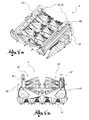
- FIGS. 1a-1c respectively show a perspective, front and top plan view of a corn-shelling machine and/or combine harvester according to an embodiment of the present invention, said machine being in operating condition;
- FIGS. 2a-2c respectively show a perspective, front and top plan view of a corn-shelling machine and/or combine harvester according to an embodiment of the present invention, said machine being in a folding step;
- FIGS. 3a-3c respectively show a perspective, front and top plan view of a corn-shelling machine and/or combine harvester according to an embodiment of the present invention, said machine being in a further folding step;
- FIGS. 4 a-4d respectively show a perspective, front, lateral and top plan view of a corn-shelling machine and/or combine harvester according to an embodiment of the present invention, said machine being in final folding condition;
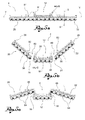
- FIGS. 5a-5e show front views of the folding steps of a corn-shelling machine and/or combine harvester according to a further embodiment of the present invention.
- reference numeral 4 globally denotes a head for a corn-shelling machine and/or combine harvester suitable for performing the shelling of cobs.
- the corn-shelling machine and/or combine harvester comprises head 4 which may be associated to a drive which has the function of carrying the head, move it, operate it and convey and harvest the cobs as they are shelled.
- head 4 comprises at least one pair of sheller rollers 8 which are counter-rotating in relation to relative rotation axes and fitted with blades (not shown) for pulling the stack of a corn on the cob plant downwards; the rotation of the sheller rollers 8 therefore is such as to obtain such downward movement or shelling of the cobs.
- head 4 is also fitted with sheller plates, arranged on top of the sheller rollers, opposite to the ground, so as to oppose resistance to the passage of the cob: in this way, the cob is torn from the stalk.
- Head 4 for a corn-shelling machine and/or combine harvester extends along a main transversal direction Y-Y, perpendicular to a longitudinal advancement direction X-X of head 4 in the working or operating step.
- Head 4 comprises a central portion 12 which extends along the main transversal direction Y-Y between opposite transversal ends 16, 18 and two lateral portions 20, 22 positioned on opposite sides to the central portion 12 at each transversal end 16, 18 and aligned with the central portion 12 in a working condition of head 4.
- the lateral portions 20, 22 are equal to each other and arranged on opposite sides relative to the central portion 12.
- Each lateral portion 20, 22 extends from an inner end 24, alongside the corresponding transversal end 16, 18 of the central portion 12 in a working configuration, to an external end 28, opposite the inner end 24 in relation to the transversal direction Y-Y, in a working configuration.
- Each lateral portion 20, 22 is operatively connected to the central portion 12 by means of the interposition of connection means 32 comprising a relative arm 34 which connects each lateral portion 20, 22 to the central portion 12.
- connection means 32 comprise a first hinge 36 defining a first rotation axis R' parallel to the longitudinal direction X-X of advancement of the head 4, so as to separate and raise the lateral portions 20, 22 in relation to the central portion 12, and comprising a second hinge 40 defining a second rotation axis R", perpendicular to the first rotation axis R', so as to rotate the lateral portions 20, 22 in reciprocal approach towards a centreline plane M-M of the central portion 12 and to position them on a plane substantially perpendicular to said transversal direction Y-Y.
- the head 4 further comprises drive means 44 for moving the lateral portions 20, 22 so as to pass from a working configuration wherein the lateral portions 20, 22 are alongside and aligned with the central portion 12, to a folded configuration wherein the lateral portions 20, 22 are at least partially folded and overlapping the central portion 12.
- the drive means preferably are hydraulic and/or pneumatic drive motors, such as cylinders and respective pistons or stems of the hydraulic and/or pneumatic type.
- the drive means 44 are operatively connected to the connection means 32 and/or to the lateral portions 20, 22 so as to move the lateral portions 20, 22 in relation to said first and second hinge 36, 40, folding them at least partially onto the central portion 12.
- first and the second hinge 36, 40 are positioned at a first connection end 48 of arm 34 to the central portion 12.
- first drive means 45 are positioned at said first connection end 48 of arm 34 to the central portion 12 so as to control the rotation movements of the lateral portion 20, 22 in relation to the first and second hinge 36, 40.
- Arm 34 is in turn connected to the lateral portion 20, 22 at a second connection end 52 at which a third hinge 56 is positioned, defining a third rotation axis R"' parallel to the first rotation axis R', when head 4 is in a working configuration.
- the second connection end 52 is positioned between a centreline S of the lateral portion 20, 22 and said inner end 24 of the same lateral portion.
- arm 34 is U-shaped so as to delimit a concave seat 60 facing the lateral portion 20, 22 and so as to permit the rotation of the lateral portion 20, 22 around the third rotation axis R"', said concave seat 60 housing at least partially the section of lateral portion 20, 22 included between the second connection end 52 and the inner end 24 of the lateral portion 20, 22, during the rotation of the latter around the third rotation axis R"'.
- arm 34 is fitted with second drive means 46 positioned at the second end 52 so as to move the lateral portion 20, 22 in relation to the third hinge 56.
- each lateral portion 20, 22 is in turn composed of a pair of sections 64 alongside and hinged to each other in relation to a fourth hinge 68 defining a fourth rotation axis W parallel to the first rotation axis R' in a working configuration of head 4, it being possible to fold back the sections 64 on to each other.
- the lateral portion 20, 22 preferably comprises drive means (not shown) positioned on the lateral portion 20, 22 itself so as to allow the folding of sections 64 relative to said fourth hinge 68.
- sections 64 substantially have a transversal dimension equal to half the transversal dimension of the lateral portion 20, 22.
- the central portion 12 has a transversal extension T less than or equal to a third of the total transversal extension V of head 4 in a working configuration.
- the lateral portions 20, 22 are fitted with front tips 76 positioned frontally to the sheller rollers 8 so as to intercept the cobs before the rollers, wherein said front tips 76 comprise a rear portion 80 facing roller 8, and a front portion 84, opposite the rear portion 80.
- the front portion 84 is hinged to the rear portion 80 in relation to a tip axis 88 parallel to the main transversal direction Y-Y in a working configuration, so as to be able to overlap the front portion 84 on the rear portion 80 in a folded configuration of head 4.
- the head is fitted with drive means for moving and folding the front tips 76 relative to the rear tips 80.
- head 4 is positioned in a working configuration wherein the lateral portions 20, 22 are aligned in relation to the central portion 12 ( figure 1a-1c , 5a ).
- the lateral portions 20, 22 are rotated around the first hinge 36, defining the first rotation axis R', so as to separate and raise the lateral portions 20, 22 in relation to the central portion 12 ( figures 2a-2c , 5b) . Then, the lateral portions 20, 22 are rotated around the second hinge 40 defining a second rotation axis R' perpendicular to the first rotation axis R', so as to rotate the lateral portions 20, 22 in reciprocal approach towards a centreline plane M-M of the central portion 12 and to position them on a plane substantially perpendicular to said transversal direction Y-Y ( figures 4a-4d , 5e ).
- Arm 34 is U-shaped so as to delimit a concave seat 60 facing the lateral portion 20, 22; the lateral portion 20, 22 is then rotated around the third rotation axis R"', so that said concave seat 60 houses at least partially the section of lateral portion 20, 22 included between the second connection end 52 and the inner end 24 of the lateral portion 20, 22, during the rotation of the latter around the third rotation axis R"' ( figures 3a-3c ; 5c ).
- the step of rotating the lateral portions 20, 22 around the third rotation axis R"' is carried out before the step of rotating the lateral portions 20, 22 around the second rotation axis R".
- the lateral portions 20, 22 with front tips 76 positioned frontally to the sheller rollers 8 so as to intercept the cobs before the same rollers.
- the front tips are fitted with rear portion 80 and front portion 84; the folding steps contemplates rotating the front portion 84 so as to overlap it on the rear portion 80 in a folded configuration of head 4, said rotation of the front portion 84 being performed before the rotation of the lateral portions 20, 22 in reciprocal approach towards the centreline plane M-M of the central portion 12 ( figures 4a-4d , 5e ).
- the corn-shelling machine and/or combine harvester according to the invention allows the drawbacks of the prior art to be overcome.
- the head can be folded so as to have a total transversal dimension equal to about one third compared to the total transversal dimension in operating condition.
- the folding operation occurs in a quick and optionally automated manner so as not to require the manual intervention.
- the head can therefore be easily carried on a combine harvester without requiring the intervention of oversize load means. This simplifies the transport of the head which is easy and cost-effective.
Landscapes
- Life Sciences & Earth Sciences (AREA)
- Environmental Sciences (AREA)
- Harvesting Machines For Specific Crops (AREA)
- Agricultural Machines (AREA)
- Manufacturing And Processing Devices For Dough (AREA)
- Bakery Products And Manufacturing Methods Therefor (AREA)
Abstract
Description
- The present invention relates to a folding head for a corn-shelling machine and/or combine harvester suitable for performing the detachment or shelling of the cobs of the relative stem or stalk of cob plants. The present invention also relates to a method of folding back a head for a corn-shelling machine and/or combine harvester.
- In particular, the head is placed in front of the corn-shelling machine and/or combine harvester and is provided with a plurality of devices suitable for carrying out the shelling of cobs.
- The head usually has considerable transversal dimensions, i.e. perpendicular to the advancement direction of the corn-shelling machine and/or combine harvester in order to harvest as many cobs as possible upon each passage.
- Such transversal dimensions may also exceed 10 meters. The heads often need to be removed from the machine and carried, for example by means of a combine harvester. In order to be carried on combine harvesters, it is essential to be able to fold said heads.
- Solutions of folding heads for corn-shelling machines and/or combine harvesters are known in the art, wherein the head comprises a central portion and two lateral portions hinged at opposite sides to the central portion. The hinge axes are arranged parallel to the advancement direction of the head. The central portion has an extension equal to half the total transversal extension of the head while each lateral portion has a transversal extension equal to ¼ of the total extension. In this way, each lateral portion can be upturned on top of the central portion and in folded configuration, the head takes on a transversal size equal to half the maximum size in working configuration.
- However, such known solution has some limitations since the total dimensions are still equal to half the maximum ones: this means that for larger heads, such dimensions in folded configuration will still be equal to 5-6 m. Such dimensions are excessive for the dimensions of the combine harvester and require the use of oversize loads with the relative security and the relative transport cost.
- The object of the present invention is to provide a head for a corn-shelling machine and/or combine harvester which should solve the drawbacks mentioned with reference to the prior art.
- In particular, the object of the present invention is to provide a head for a corn-shelling machine and/or combine harvester which, in folded configuration, can reduce as much as possible the dimensions so as to be easily coupled on a combine harvester so as to fall within the combine harvester profile and not require the use of oversize loads; at the same time, said head must be reliable without impairing the functions of cob harvesting when in working configuration.
- Such object is achieved by a head for a corn-shelling machine and/or combine harvester according to
claim 1 and by a method of folding back a head for a corn-shelling machine and/or combine harvester according to claim 13. - Other embodiments of the present invention are described in the subsequent claims.
- Further features and the advantages of the present invention will appear more clearly from the following description of preferred non-limiting embodiments thereof, in which:
-
figures 1a-1c respectively show a perspective, front and top plan view of a corn-shelling machine and/or combine harvester according to an embodiment of the present invention, said machine being in operating condition; -
figures 2a-2c respectively show a perspective, front and top plan view of a corn-shelling machine and/or combine harvester according to an embodiment of the present invention, said machine being in a folding step; -
figures 3a-3c respectively show a perspective, front and top plan view of a corn-shelling machine and/or combine harvester according to an embodiment of the present invention, said machine being in a further folding step; -
figures 4 a-4d respectively show a perspective, front, lateral and top plan view of a corn-shelling machine and/or combine harvester according to an embodiment of the present invention, said machine being in final folding condition; -
figures 5a-5e show front views of the folding steps of a corn-shelling machine and/or combine harvester according to a further embodiment of the present invention. - Elements or parts of elements in common between the embodiments described below are referred to with the same reference numerals.
- With reference to the above figures,
reference numeral 4 globally denotes a head for a corn-shelling machine and/or combine harvester suitable for performing the shelling of cobs. - The corn-shelling machine and/or combine harvester comprises
head 4 which may be associated to a drive which has the function of carrying the head, move it, operate it and convey and harvest the cobs as they are shelled. - In a known manner,
head 4 comprises at least one pair ofsheller rollers 8 which are counter-rotating in relation to relative rotation axes and fitted with blades (not shown) for pulling the stack of a corn on the cob plant downwards; the rotation of thesheller rollers 8 therefore is such as to obtain such downward movement or shelling of the cobs. - According to an embodiment,
head 4 is also fitted with sheller plates, arranged on top of the sheller rollers, opposite to the ground, so as to oppose resistance to the passage of the cob: in this way, the cob is torn from the stalk. - Head 4 for a corn-shelling machine and/or combine harvester extends along a main transversal direction Y-Y, perpendicular to a longitudinal advancement direction X-X of
head 4 in the working or operating step. -
Head 4 comprises acentral portion 12 which extends along the main transversal direction Y-Y between oppositetransversal ends lateral portions central portion 12 at eachtransversal end central portion 12 in a working condition ofhead 4. - Preferably, the
lateral portions central portion 12. - Each
lateral portion inner end 24, alongside the correspondingtransversal end central portion 12 in a working configuration, to anexternal end 28, opposite theinner end 24 in relation to the transversal direction Y-Y, in a working configuration. - Each
lateral portion central portion 12 by means of the interposition of connection means 32 comprising a relative arm 34 which connects eachlateral portion central portion 12. - In particular, the connection means 32 comprise a
first hinge 36 defining a first rotation axis R' parallel to the longitudinal direction X-X of advancement of thehead 4, so as to separate and raise thelateral portions central portion 12, and comprising asecond hinge 40 defining a second rotation axis R", perpendicular to the first rotation axis R', so as to rotate thelateral portions central portion 12 and to position them on a plane substantially perpendicular to said transversal direction Y-Y. - The
head 4 further comprises drive means 44 for moving thelateral portions lateral portions central portion 12, to a folded configuration wherein thelateral portions central portion 12. - The drive means preferably are hydraulic and/or pneumatic drive motors, such as cylinders and respective pistons or stems of the hydraulic and/or pneumatic type.
- The drive means 44 are operatively connected to the connection means 32 and/or to the
lateral portions lateral portions second hinge central portion 12. - According to an embodiment, the first and the
second hinge first connection end 48 of arm 34 to thecentral portion 12. - According to an embodiment, first drive means 45 are positioned at said
first connection end 48 of arm 34 to thecentral portion 12 so as to control the rotation movements of thelateral portion second hinge - Arm 34 is in turn connected to the
lateral portion second connection end 52 at which athird hinge 56 is positioned, defining a third rotation axis R"' parallel to the first rotation axis R', whenhead 4 is in a working configuration. - Preferably, the
second connection end 52 is positioned between a centreline S of thelateral portion inner end 24 of the same lateral portion. - Preferably, arm 34 is U-shaped so as to delimit a
concave seat 60 facing thelateral portion lateral portion concave seat 60 housing at least partially the section oflateral portion second connection end 52 and theinner end 24 of thelateral portion - Preferably, arm 34 is fitted with second drive means 46 positioned at the
second end 52 so as to move thelateral portion third hinge 56. - According to a further embodiment, each
lateral portion sections 64 alongside and hinged to each other in relation to afourth hinge 68 defining a fourth rotation axis W parallel to the first rotation axis R' in a working configuration ofhead 4, it being possible to fold back thesections 64 on to each other. - The
lateral portion lateral portion sections 64 relative to saidfourth hinge 68. - Preferably,
sections 64 substantially have a transversal dimension equal to half the transversal dimension of thelateral portion - Preferably, the
central portion 12 has a transversal extension T less than or equal to a third of the total transversal extension V ofhead 4 in a working configuration. - According to an embodiment, the
lateral portions front tips 76 positioned frontally to thesheller rollers 8 so as to intercept the cobs before the rollers, wherein saidfront tips 76 comprise a rear portion 80 facingroller 8, and afront portion 84, opposite the rear portion 80. In particular, thefront portion 84 is hinged to the rear portion 80 in relation to atip axis 88 parallel to the main transversal direction Y-Y in a working configuration, so as to be able to overlap thefront portion 84 on the rear portion 80 in a folded configuration ofhead 4. According to a possible embodiment, the head is fitted with drive means for moving and folding thefront tips 76 relative to the rear tips 80. - The method of folding back a head for a corn-shelling machine and/or combine harvester according to the invention will now be described.
- In particular,
head 4 is positioned in a working configuration wherein thelateral portions figure 1a-1c ,5a ). - The
lateral portions first hinge 36, defining the first rotation axis R', so as to separate and raise thelateral portions figures 2a-2c ,5b) . Then, thelateral portions second hinge 40 defining a second rotation axis R' perpendicular to the first rotation axis R', so as to rotate thelateral portions central portion 12 and to position them on a plane substantially perpendicular to said transversal direction Y-Y (figures 4a-4d ,5e ). - It is also possible to position an arm 34 connected to the
lateral portion second connection end 52 wherein, at saidsecond connection end 52, athird hinge 56 is positioned defining a third rotation axis R"' parallel to the first rotation axis R', whenhead 4 is in a working configuration. Arm 34 is U-shaped so as to delimit aconcave seat 60 facing thelateral portion lateral portion concave seat 60 houses at least partially the section oflateral portion second connection end 52 and theinner end 24 of thelateral portion figures 3a-3c ;5c ). - Preferably, the step of rotating the
lateral portions lateral portions - In the version of
head 4 provided withlateral portions sections 64, it is preferable to foldsections 64 on themselves (figure 5d ) after rotating thelateral portions figure 5c ) and before rotating the samelateral portions figure 5e ). - It is also possible to fit the
lateral portions front tips 76 positioned frontally to thesheller rollers 8 so as to intercept the cobs before the same rollers. The front tips are fitted with rear portion 80 andfront portion 84; the folding steps contemplates rotating thefront portion 84 so as to overlap it on the rear portion 80 in a folded configuration ofhead 4, said rotation of thefront portion 84 being performed before the rotation of thelateral portions figures 4a-4d ,5e ). - As can be understood from the description, the corn-shelling machine and/or combine harvester according to the invention allows the drawbacks of the prior art to be overcome.
- In fact, the head can be folded so as to have a total transversal dimension equal to about one third compared to the total transversal dimension in operating condition.
- The folding operation occurs in a quick and optionally automated manner so as not to require the manual intervention.
- The head can therefore be easily carried on a combine harvester without requiring the intervention of oversize load means. This simplifies the transport of the head which is easy and cost-effective.
- Thanks to the present invention it is therefore possible to easily fold and carry even heads comprising 17 front tips and having a transversal dimension of more than 12 meters in operating condition.
- A man skilled in the art may make several changes and adjustments to the corn-shelling machines and/or combine harvesters and to the methods described above in order to meet specific and incidental needs, all falling within the scope of protection defined in the following claims.
Claims (15)
- Folding head (4) for a corn-shelling machine and/or combine harvester suitable for performing the shelling of cobs, the head (4) extending in a transversal direction (Y-Y), perpendicular to a longitudinal direction (X-X) of advancement of the head (4) in the working step, and comprising at least one sheller roller (8) rotating in relation to a relative rotation axis and fitted with blades to pull a stalk of a corn on the cob plant downwards,- the head (4) comprising a central portion (12) extending along the main transversal direction (Y-Y) between opposite transversal ends (16, 18)and two lateral portions (20, 22) positioned on opposite sides to the central portion (12) at each transversal end (16, 18) and aligned with the central portion (12) in a working condition of the head (4),- each lateral portion (20, 22) extending from an inner end (24), alongside the corresponding transversal end (16, 18) of the central portion (12) in a working configuration, to an external end (28), opposite the inner end (24) in relation to the transversal direction (Y-Y), in a working configuration,- the head (4) comprising drive means (44) for moving the lateral portions (20, 22) so as to pass from a working configuration wherein the lateral portions (20, 22) are alongside and aligned with the central portion (12), to a folded configuration wherein the lateral portions (20, 22) are at least partially folded and overlapping the central portion (12),
characterised in that- each lateral portion (20, 22) is operatively connected to the central portion (12) by means of the interposition of connection means (32) comprising a relative arm (34) which connects each lateral portion (20, 22) to the central portion (12),- wherein the connection means (32) comprise a first hinge (36) defining a first rotation axis (R') parallel to the longitudinal direction (X-X) of advancement of the head (4), so as to separate and raise the lateral portions (20, 22) in relation to the central portion (12), and comprising a second hinge (40) defining a second rotation axis (R"), perpendicular to the first rotation axis (R'), so as to rotate the lateral portions (20, 22) in reciprocal approach towards a centreline plane (M-M) of the central portion (12) and to position them on a plane substantially perpendicular to said transversal direction (Y-Y). - Head (4) according to claim 1, wherein the drive means (44) are operatively connected to the connection means (32) and/or to the lateral portions (20, 22) so as to move the lateral portions (20, 22) in relation to said first and second hinge (36, 40), folding them at least partially onto the central portion (12).
- Head (4) according to claim 1 or 2, wherein the first and second hinge (36, 40) are positioned at a first connection end (48) of the arm (34) to the central portion (12).
- Head (4) according to claim 1, 2 or 3, wherein first drive means (45) are positioned at a first connection end (48) of the arm (34) to the central portion (12) so as to control the rotation movements of the lateral portion (20, 22) in relation to the first and second hinge (36, 40).
- Head (4) according to any of the claims from 2 to 5, wherein the arm (34) is connected to the lateral portion (20, 22) at a second connection end (52) at which a third hinge (56) is positioned defining a third rotation axis (R"') parallel to the first rotation axis (R'), when the head (4) is in a working configuration.
- Head (4) according to claim 5, wherein said second connection end (52) is positioned between a centreline of the lateral portion (20, 22) and said inner end (24) of the same lateral portion.
- Head (4) according to any one of claims from 5 to 6, wherein the arm (34) is U-shaped so as to delimit a concave seat (60) facing the lateral portion (20, 22) and so as to permit the rotation of the lateral portion (20, 22) around the third rotation axis (R"'), said concave seat (60) housing at least partially the section of lateral portion (20, 22) included between the second connection end (52) and the inner end (24) of the lateral portion (20, 22), during the rotation of the latter around the third rotation axis (R"').
- Head (4) according to any one of claims from 5 to 7, wherein the arm (34) is fitted with second drive means (46) positioned at the second connection end (52) so as to move the lateral portion (20, 22) in relation to the third hinge (56).
- Head (4) according to any one of the preceding claims, wherein each lateral portion (20, 22) is in turn composed of a pair of sections (64) alongside and hinged to each other in relation to a fourth hinge (68) defining a fourth rotation axis (W) parallel to the first rotation axis (R') in a working configuration of the head (4), it being possible to fold back the sections (64) on to each other.
- Head (4) according to claim 9, wherein said sections (64) substantially have a transversal dimension equal to half the transversal dimension of the lateral portion (20, 22).
- Head (4) according to any one of the preceding claims, wherein the central portion (12) has a transversal extension (T) less than or equal to a third of the total transversal extension (V) of the head (4) in a working configuration.
- Head (4) according to any one of the preceding claims, wherein the lateral portions (20, 22) are fitted with front tips (76) positioned frontally to the sheller rollers (8) so as to intercept the cobs before the rollers, wherein said front tips (76) comprise a rear portion (80) facing the roller (8), and a front portion (84), opposite the rear portion (80), the front portion (84) being hinged to the rear portion (80) in relation to a tip axis (88) parallel to the main transversal direction (Y-Y) in a working configuration, so as to be able to overlap the front portion (84) on the rear portion (80) in a folded configuration of the head (4).
- Method of folding back a head for a corn-shelling machine and/or combine harvester comprising the steps of:- predisposing a head (4) for a corn-shelling machine and/or combine harvester according to any one of claims from 1 to 13,- positioning said head (4) in a working configuration wherein the lateral portions (20, 22) are aligned in relation to the central portion (12),- rotating the lateral portions (20,22) around the first hinge (36) defining a first rotation axis (R') parallel to the longitudinal direction (X-X) of advancement of the head (4), so as to separate and raise the lateral portions (20, 22) in relation to the central portion (12),- rotating the lateral portions (20, 22) around the second hinge (40) defining a second rotation axis (R') perpendicular to the first rotation axis (R'), so as to rotate the lateral portions (20, 22) in reciprocal approach towards a centreline plane (M-M) of the central portion (12) and to position them on a plane substantially perpendicular to said transversal direction (Y-Y).
- Method of folding according to claim 13, comprising the steps of:- positioning an arm (34) connected to the lateral portion (20, 22) at a second connection end (52) wherein, at said second connection end (52), a third hinge (56) is positioned defining a third rotation axis (R"') parallel to the first rotation axis (R'), when the head (4) is in a working configuration,- wherein the arm (34) is U-shaped so as to delimit a concave seat (60) facing the lateral portion (20, 22)- rotating the lateral portion (20, 22) around the third rotation axis (R"') so that said concave seat (60) houses at least partially the section of lateral portion (20, 22) included between the second connection end (52) and the inner end (24) of the lateral portion (20, 22), during the rotation of the latter around the third rotation axis (R"').
- Method of folding according to claim 13 or 14, comprising the steps of:- fitting the lateral portions (20, 22) with front tips (76) positioned frontally to the sheller rollers so as to intercept the cobs before the rollers,- the front tips (76) comprising a rear portion (80) facing the rollers (8), and a front portion (84), opposite the rear portion (80), the front portion (84) being hinged to the rear portion (80) in relation to a tip axis (88) parallel to the main transversal direction (Y-Y) in a working configuration,- rotating the front portion (84) so as to be able to overlap it on the rear portion (80) in a folded configuration of the head, said rotation of the front portion being performed before the rotation of the lateral portions (20,22) in reciprocal approach towards the centreline plane (M-M) of the central portion (12).
Priority Applications (1)
| Application Number | Priority Date | Filing Date | Title |
|---|---|---|---|
| PL13177896T PL2695509T3 (en) | 2012-08-06 | 2013-07-24 | Folding head for a corn-shelling machine and/or combine harvester and method of folding back a head for a corn-shelling machine and/or combine harvester |
Applications Claiming Priority (1)
| Application Number | Priority Date | Filing Date | Title |
|---|---|---|---|
| IT000242A ITPD20120242A1 (en) | 2012-08-06 | 2012-08-06 | FOLDABLE HEAD FOR BRAIDING AND / OR HARVESTING MACHINE AND FILLING METHOD OF A BANNER MILLING AND / OR HARVESTING MACHINE |
Publications (2)
| Publication Number | Publication Date |
|---|---|
| EP2695509A1 true EP2695509A1 (en) | 2014-02-12 |
| EP2695509B1 EP2695509B1 (en) | 2015-03-18 |
Family
ID=46939832
Family Applications (1)
| Application Number | Title | Priority Date | Filing Date |
|---|---|---|---|
| EP13177896.1A Active EP2695509B1 (en) | 2012-08-06 | 2013-07-24 | Folding head for a corn-shelling machine and/or combine harvester and method of folding back a head for a corn-shelling machine and/or combine harvester |
Country Status (6)
| Country | Link |
|---|---|
| US (1) | US9173345B2 (en) |
| EP (1) | EP2695509B1 (en) |
| ES (1) | ES2539617T3 (en) |
| HU (1) | HUE026523T2 (en) |
| IT (1) | ITPD20120242A1 (en) |
| PL (1) | PL2695509T3 (en) |
Cited By (4)
| Publication number | Priority date | Publication date | Assignee | Title |
|---|---|---|---|---|
| EP3090619A1 (en) * | 2015-05-07 | 2016-11-09 | CLAAS Hungaria Kft. | Auxiliary device for harvesting crops arranged in rows |
| EP3440918A1 (en) * | 2017-08-08 | 2019-02-13 | CNH Industrial Belgium NV | Foldable corn head |
| EP3278653B1 (en) | 2016-08-05 | 2019-04-10 | CNH Industrial Belgium nv | Agricultural machine with folding header |
| US20220015293A1 (en) * | 2020-07-17 | 2022-01-20 | Deere & Company | Folding harvester with crop divider lift and frame lock |
Families Citing this family (24)
| Publication number | Priority date | Publication date | Assignee | Title |
|---|---|---|---|---|
| US8635842B2 (en) * | 2009-08-05 | 2014-01-28 | Kevin Markt | Flexible row crop header for an agricultural harvester |
| FR3013557B1 (en) * | 2013-11-22 | 2016-01-01 | Kuhn Sa | AGRICULTURAL MACHINE, IN PARTICULAR A MACHINE FOR THE HARVEST OF PLANTS, COMPRISING TWO ARTICULATED WORKING UNITS JOINED TO A SINGLE ARM |
| BE1022461B1 (en) * | 2014-09-10 | 2016-04-07 | Cnh Industrial Belgium Nv | CUTBOARD BAR WHOLE AND METHOD FOR ITS USE |
| BR102016005189B1 (en) * | 2015-03-13 | 2020-11-17 | Cnh Industrial Belgium Nv | AGRICULTURAL HARVESTER |
| CN104969721A (en) * | 2015-07-02 | 2015-10-14 | 济南大学 | Folding corn header and docking mechanism thereof |
| CN106258222A (en) * | 2016-10-17 | 2017-01-04 | 济南大学 | A kind of ceding of Taiwan fold mechanism |
| BE1024679B1 (en) * | 2016-10-21 | 2018-05-22 | Cnh Industrial Belgium Nv | FOLDABLE CUTBOARD |
| IT201600131283A1 (en) * | 2016-12-27 | 2018-06-27 | Capello S R L | Harvesting head for a cereal harvesting machine |
| US10375882B2 (en) * | 2017-04-19 | 2019-08-13 | Cnh Industrial America Llc | Multi-sectional header frame |
| US10375881B2 (en) | 2017-05-23 | 2019-08-13 | Cnh Industrial America Llc | Agricultural machine with sectional header |
| US10433483B2 (en) | 2017-08-21 | 2019-10-08 | Cnh Industrial America Llc | Agricultural header with one or more movable wing sections |
| US10537063B2 (en) * | 2017-10-11 | 2020-01-21 | Deere & Company | Folding agricultural head |
| US10426088B2 (en) | 2017-10-11 | 2019-10-01 | Deere & Company | Center feed assembly for a draper |
| US10433486B2 (en) | 2017-10-16 | 2019-10-08 | Deere & Company | System and method for wing float on a combine draper header |
| US10568266B2 (en) | 2017-10-17 | 2020-02-25 | Deere & Company | Self-contained combine draper wing leveler |
| US10813289B2 (en) * | 2018-06-05 | 2020-10-27 | Deere & Company | Single top beam folding corn head mainframe |
| NL2021519B1 (en) * | 2018-08-30 | 2020-04-24 | Ploeger Oxbo Europe B V | Self-propelled agricultural machine, for example a self-propelled belt rake |
| US10897846B2 (en) * | 2018-10-31 | 2021-01-26 | Deere & Company | Corn harvester |
| US12052951B2 (en) | 2018-11-06 | 2024-08-06 | Cnh Industrial America Llc | Remotely adjustable row divider for an agricultural harvester |
| WO2020102209A1 (en) * | 2018-11-16 | 2020-05-22 | Cnh Industrial America Llc | System and method for setting parameters for a multi-segment agricultural header |
| USD900886S1 (en) * | 2019-01-15 | 2020-11-03 | Deere & Company | Row unit crop guides |
| US11490568B2 (en) | 2020-03-11 | 2022-11-08 | Deere & Company | Pivoting apparatus for row head |
| US11785890B2 (en) * | 2020-06-17 | 2023-10-17 | Deere & Company | Corn head adjustment system with integrated actuation |
| CN116369047B (en) * | 2023-05-11 | 2025-09-05 | 潍柴雷沃智慧农业科技股份有限公司 | A harvester adaptive peeling control method, device and storage medium |
Citations (5)
| Publication number | Priority date | Publication date | Assignee | Title |
|---|---|---|---|---|
| EP0131853A1 (en) * | 1983-07-07 | 1985-01-23 | Carl Geringhoff GmbH & Co KG | Maize harvester |
| DE3828293C1 (en) * | 1988-08-19 | 1990-01-25 | Karl Mengele & Soehne Maschinenfabrik & Eisengiesserei Gmbh & Co Kg, 8870 Guenzburg, De | Harvesting attachment |
| EP0750833A1 (en) * | 1995-06-27 | 1997-01-02 | Claas Saulgau Gmbh | Harvester head on agricultural machines for feeding and conveying stem crops |
| EP1051895A2 (en) * | 1999-05-14 | 2000-11-15 | Claas Saulgau Gmbh | Agricultural working machine control |
| EP1932416A1 (en) * | 2006-12-15 | 2008-06-18 | Claas Saulgau Gmbh | Device comprising a first and a second work unit |
Family Cites Families (26)
| Publication number | Priority date | Publication date | Assignee | Title |
|---|---|---|---|---|
| NL267274A (en) * | 1961-07-19 | |||
| NL6414183A (en) * | 1964-12-05 | 1966-06-06 | ||
| NL6401807A (en) * | 1964-02-26 | 1965-08-27 | ||
| NL6402194A (en) * | 1964-03-05 | 1965-09-06 | ||
| NL6701059A (en) * | 1967-01-24 | 1968-07-25 | ||
| NL6903371A (en) * | 1969-03-05 | 1970-09-08 | ||
| DK143121C (en) * | 1978-12-12 | 1981-12-14 | Kongskilde Koncernselskab As | TOOL BOOM, NAME FOR AGRICULTURAL PURPOSES |
| US4409780A (en) * | 1982-03-11 | 1983-10-18 | Kansas State University Research Foundation | Folding header assembly |
| US4487004A (en) * | 1983-06-03 | 1984-12-11 | Kejr Melvin P | Combine harvester apparatus |
| US4903470A (en) * | 1987-09-14 | 1990-02-27 | Claas Ohg | Self-propelling harvester thresher with two-part cutting mechanism |
| US5673543A (en) * | 1996-01-04 | 1997-10-07 | Byron Enterprises, Inc | Foldable corn head with unobstructed auger |
| US5724798A (en) * | 1996-07-08 | 1998-03-10 | Byron Enterprises Inc. | Latch for a folding corn head |
| DE19635992A1 (en) * | 1996-09-05 | 1998-03-12 | Same Spa | Self-propelled agricultural harvester |
| US5960618A (en) * | 1997-01-09 | 1999-10-05 | Case Corporation | Row unit crop guide for harvesting multiple rows |
| DE10039097A1 (en) * | 2000-08-07 | 2002-02-21 | Claas Saulgau Gmbh | Method and device for pivoting the dividers of multi-part agricultural harvesters |
| DE10142978A1 (en) * | 2001-09-01 | 2003-03-20 | Kemper Gmbh Maschf | header |
| HUP0300512A2 (en) * | 2002-03-28 | 2004-09-28 | Claas Saulgau Gmbh | Reaper knife |
| DE10221983A1 (en) * | 2002-05-17 | 2003-11-27 | Kemper Gmbh Maschf | header |
| DE10250337A1 (en) * | 2002-10-29 | 2004-05-19 | Maschinenfabrik Kemper Gmbh & Co. Kg | Adjustment device for a header |
| DE10303380A1 (en) * | 2003-01-29 | 2004-08-05 | Claas Saulgau Gmbh | Agricultural harvester, comprising front attachment to be swiveled into particularly safe position for transport |
| US7404283B2 (en) * | 2003-08-06 | 2008-07-29 | Deere & Company | Crop collecting assembly for an agricultural harvester |
| DE10354977A1 (en) * | 2003-11-25 | 2005-06-30 | Maschinenfabrik Kemper Gmbh & Co. Kg | Cross auger for a header |
| DE102005016350A1 (en) * | 2005-04-09 | 2006-10-12 | Maschinenfabrik Kemper Gmbh & Co. Kg | Harvest header for agricultural harvesters |
| US7426817B2 (en) * | 2006-03-02 | 2008-09-23 | Deere & Company | Independent center reel position adjustment for an agricultural harvesting machine |
| US7918076B2 (en) * | 2006-09-25 | 2011-04-05 | Macdon Industries Ltd. | Device for maintaining wing balance on a multi-section header |
| US7614206B2 (en) * | 2007-06-04 | 2009-11-10 | Claas Selbstfahrende Erntemaschinen Gmbh | Winged header apparatus and method for a combine |
-
2012
- 2012-08-06 IT IT000242A patent/ITPD20120242A1/en unknown
-
2013
- 2013-07-24 PL PL13177896T patent/PL2695509T3/en unknown
- 2013-07-24 ES ES13177896.1T patent/ES2539617T3/en active Active
- 2013-07-24 HU HUE13177896A patent/HUE026523T2/en unknown
- 2013-07-24 EP EP13177896.1A patent/EP2695509B1/en active Active
- 2013-07-31 US US13/955,031 patent/US9173345B2/en active Active
Patent Citations (5)
| Publication number | Priority date | Publication date | Assignee | Title |
|---|---|---|---|---|
| EP0131853A1 (en) * | 1983-07-07 | 1985-01-23 | Carl Geringhoff GmbH & Co KG | Maize harvester |
| DE3828293C1 (en) * | 1988-08-19 | 1990-01-25 | Karl Mengele & Soehne Maschinenfabrik & Eisengiesserei Gmbh & Co Kg, 8870 Guenzburg, De | Harvesting attachment |
| EP0750833A1 (en) * | 1995-06-27 | 1997-01-02 | Claas Saulgau Gmbh | Harvester head on agricultural machines for feeding and conveying stem crops |
| EP1051895A2 (en) * | 1999-05-14 | 2000-11-15 | Claas Saulgau Gmbh | Agricultural working machine control |
| EP1932416A1 (en) * | 2006-12-15 | 2008-06-18 | Claas Saulgau Gmbh | Device comprising a first and a second work unit |
Cited By (8)
| Publication number | Priority date | Publication date | Assignee | Title |
|---|---|---|---|---|
| EP3090619A1 (en) * | 2015-05-07 | 2016-11-09 | CLAAS Hungaria Kft. | Auxiliary device for harvesting crops arranged in rows |
| EP3278653B1 (en) | 2016-08-05 | 2019-04-10 | CNH Industrial Belgium nv | Agricultural machine with folding header |
| EP3278653B2 (en) † | 2016-08-05 | 2022-06-29 | CNH Industrial Belgium nv | Agricultural machine with folding header |
| USRE49178E1 (en) | 2016-08-05 | 2022-08-23 | Blue Leaf I.P., Inc. | Agricultural machine with folding header |
| EP3440918A1 (en) * | 2017-08-08 | 2019-02-13 | CNH Industrial Belgium NV | Foldable corn head |
| US10820509B2 (en) | 2017-08-08 | 2020-11-03 | Cnh Industrial America Llc | Foldable corn head |
| US20220015293A1 (en) * | 2020-07-17 | 2022-01-20 | Deere & Company | Folding harvester with crop divider lift and frame lock |
| US11570950B2 (en) * | 2020-07-17 | 2023-02-07 | Deere & Company | Folding harvester with crop divider lift and frame lock |
Also Published As
| Publication number | Publication date |
|---|---|
| HUE026523T2 (en) | 2016-06-28 |
| ITPD20120242A1 (en) | 2014-02-07 |
| US20140033670A1 (en) | 2014-02-06 |
| US9173345B2 (en) | 2015-11-03 |
| EP2695509B1 (en) | 2015-03-18 |
| PL2695509T3 (en) | 2015-09-30 |
| ES2539617T3 (en) | 2015-07-02 |
Similar Documents
| Publication | Publication Date | Title |
|---|---|---|
| EP2695509B1 (en) | Folding head for a corn-shelling machine and/or combine harvester and method of folding back a head for a corn-shelling machine and/or combine harvester | |
| US12342758B2 (en) | Actuated stripper plate mechanism for a harvester | |
| EP0750833B1 (en) | Harvester head for agricultural machines for feeding and conveying stem crops | |
| US10743466B2 (en) | Harvesting header for a grain harvesting machine | |
| EP2255610B1 (en) | Header for harvesting stalk plants | |
| CN105309107A (en) | Cutting device for agricultural harvesters | |
| EP2067397B1 (en) | Harvester head to gather and transport cereals in an agricultural harvesting machine | |
| US20160183462A1 (en) | Grain header with swathing and chopping capability | |
| EP3469877B1 (en) | Header for combine harvester | |
| US8387998B2 (en) | Steering mechanism for a sugarcane harvester | |
| CN107257621A (en) | The harvesting panel control system of agricultural cutter header | |
| US9386745B2 (en) | Corn header for a forage harvester including a side separating mechanism | |
| BR112019017610B1 (en) | HARVEST REEL FOR AN AGRICULTURAL HARVESTER | |
| DE102008020240A1 (en) | Harvesting attachment for harvesting stalky crops | |
| BR102019008401B1 (en) | Row crop harvester and crop divider for an agricultural machine, and, combined | |
| BE1022461B1 (en) | CUTBOARD BAR WHOLE AND METHOD FOR ITS USE | |
| EP2727452B1 (en) | A reel for an agricultural harvesting head | |
| US20170055450A1 (en) | Bat tube support arm design for a pick-up reel of a harvester | |
| CN108135135B (en) | Agricultural machines and associated conveyor systems for harvesting crops | |
| DE202008005596U1 (en) | Harvesting attachment for harvesting stalky crops | |
| KR20110070144A (en) | Harvesting units for harvesting crops and harvesters having the same | |
| US3541772A (en) | Fruit harvester | |
| CN103548504B (en) | A kind of adjustable threshing drum upper cover | |
| US9538705B1 (en) | Cutter and a base cut assembly | |
| DE202005007424U1 (en) | Mower bar for disc mowers |
Legal Events
| Date | Code | Title | Description |
|---|---|---|---|
| AK | Designated contracting states |
Kind code of ref document: A1 Designated state(s): AL AT BE BG CH CY CZ DE DK EE ES FI FR GB GR HR HU IE IS IT LI LT LU LV MC MK MT NL NO PL PT RO RS SE SI SK SM TR |
|
| AX | Request for extension of the european patent |
Extension state: BA ME |
|
| PUAI | Public reference made under article 153(3) epc to a published international application that has entered the european phase |
Free format text: ORIGINAL CODE: 0009012 |
|
| 17P | Request for examination filed |
Effective date: 20140228 |
|
| RBV | Designated contracting states (corrected) |
Designated state(s): AL AT BE BG CH CY CZ DE DK EE ES FI FR GB GR HR HU IE IS IT LI LT LU LV MC MK MT NL NO PL PT RO RS SE SI SK SM TR |
|
| GRAP | Despatch of communication of intention to grant a patent |
Free format text: ORIGINAL CODE: EPIDOSNIGR1 |
|
| RIC1 | Information provided on ipc code assigned before grant |
Ipc: A01D 45/02 20060101ALI20141014BHEP Ipc: A01D 41/14 20060101AFI20141014BHEP |
|
| INTG | Intention to grant announced |
Effective date: 20141028 |
|
| GRAS | Grant fee paid |
Free format text: ORIGINAL CODE: EPIDOSNIGR3 |
|
| GRAA | (expected) grant |
Free format text: ORIGINAL CODE: 0009210 |
|
| AK | Designated contracting states |
Kind code of ref document: B1 Designated state(s): AL AT BE BG CH CY CZ DE DK EE ES FI FR GB GR HR HU IE IS IT LI LT LU LV MC MK MT NL NO PL PT RO RS SE SI SK SM TR |
|
| REG | Reference to a national code |
Ref country code: GB Ref legal event code: FG4D |
|
| REG | Reference to a national code |
Ref country code: CH Ref legal event code: EP |
|
| REG | Reference to a national code |
Ref country code: IE Ref legal event code: FG4D |
|
| REG | Reference to a national code |
Ref country code: AT Ref legal event code: REF Ref document number: 715926 Country of ref document: AT Kind code of ref document: T Effective date: 20150415 |
|
| REG | Reference to a national code |
Ref country code: DE Ref legal event code: R096 Ref document number: 602013001241 Country of ref document: DE Effective date: 20150430 |
|
| REG | Reference to a national code |
Ref country code: ES Ref legal event code: FG2A Ref document number: 2539617 Country of ref document: ES Kind code of ref document: T3 Effective date: 20150702 |
|
| REG | Reference to a national code |
Ref country code: NL Ref legal event code: VDEP Effective date: 20150318 |
|
| REG | Reference to a national code |
Ref country code: NL Ref legal event code: VDEP Effective date: 20150318 |
|
| PG25 | Lapsed in a contracting state [announced via postgrant information from national office to epo] |
Ref country code: FI Free format text: LAPSE BECAUSE OF FAILURE TO SUBMIT A TRANSLATION OF THE DESCRIPTION OR TO PAY THE FEE WITHIN THE PRESCRIBED TIME-LIMIT Effective date: 20150318 Ref country code: SE Free format text: LAPSE BECAUSE OF FAILURE TO SUBMIT A TRANSLATION OF THE DESCRIPTION OR TO PAY THE FEE WITHIN THE PRESCRIBED TIME-LIMIT Effective date: 20150318 Ref country code: NO Free format text: LAPSE BECAUSE OF FAILURE TO SUBMIT A TRANSLATION OF THE DESCRIPTION OR TO PAY THE FEE WITHIN THE PRESCRIBED TIME-LIMIT Effective date: 20150618 Ref country code: HR Free format text: LAPSE BECAUSE OF FAILURE TO SUBMIT A TRANSLATION OF THE DESCRIPTION OR TO PAY THE FEE WITHIN THE PRESCRIBED TIME-LIMIT Effective date: 20150318 Ref country code: LT Free format text: LAPSE BECAUSE OF FAILURE TO SUBMIT A TRANSLATION OF THE DESCRIPTION OR TO PAY THE FEE WITHIN THE PRESCRIBED TIME-LIMIT Effective date: 20150318 |
|
| REG | Reference to a national code |
Ref country code: LT Ref legal event code: MG4D |
|
| PG25 | Lapsed in a contracting state [announced via postgrant information from national office to epo] |
Ref country code: GR Free format text: LAPSE BECAUSE OF FAILURE TO SUBMIT A TRANSLATION OF THE DESCRIPTION OR TO PAY THE FEE WITHIN THE PRESCRIBED TIME-LIMIT Effective date: 20150619 Ref country code: RS Free format text: LAPSE BECAUSE OF FAILURE TO SUBMIT A TRANSLATION OF THE DESCRIPTION OR TO PAY THE FEE WITHIN THE PRESCRIBED TIME-LIMIT Effective date: 20150318 Ref country code: LV Free format text: LAPSE BECAUSE OF FAILURE TO SUBMIT A TRANSLATION OF THE DESCRIPTION OR TO PAY THE FEE WITHIN THE PRESCRIBED TIME-LIMIT Effective date: 20150318 |
|
| PG25 | Lapsed in a contracting state [announced via postgrant information from national office to epo] |
Ref country code: NL Free format text: LAPSE BECAUSE OF FAILURE TO SUBMIT A TRANSLATION OF THE DESCRIPTION OR TO PAY THE FEE WITHIN THE PRESCRIBED TIME-LIMIT Effective date: 20150318 |
|
| REG | Reference to a national code |
Ref country code: PL Ref legal event code: T3 |
|
| PG25 | Lapsed in a contracting state [announced via postgrant information from national office to epo] |
Ref country code: CZ Free format text: LAPSE BECAUSE OF FAILURE TO SUBMIT A TRANSLATION OF THE DESCRIPTION OR TO PAY THE FEE WITHIN THE PRESCRIBED TIME-LIMIT Effective date: 20150318 Ref country code: PT Free format text: LAPSE BECAUSE OF FAILURE TO SUBMIT A TRANSLATION OF THE DESCRIPTION OR TO PAY THE FEE WITHIN THE PRESCRIBED TIME-LIMIT Effective date: 20150720 Ref country code: EE Free format text: LAPSE BECAUSE OF FAILURE TO SUBMIT A TRANSLATION OF THE DESCRIPTION OR TO PAY THE FEE WITHIN THE PRESCRIBED TIME-LIMIT Effective date: 20150318 Ref country code: RO Free format text: LAPSE BECAUSE OF FAILURE TO SUBMIT A TRANSLATION OF THE DESCRIPTION OR TO PAY THE FEE WITHIN THE PRESCRIBED TIME-LIMIT Effective date: 20150318 Ref country code: SK Free format text: LAPSE BECAUSE OF FAILURE TO SUBMIT A TRANSLATION OF THE DESCRIPTION OR TO PAY THE FEE WITHIN THE PRESCRIBED TIME-LIMIT Effective date: 20150318 |
|
| PG25 | Lapsed in a contracting state [announced via postgrant information from national office to epo] |
Ref country code: IS Free format text: LAPSE BECAUSE OF FAILURE TO SUBMIT A TRANSLATION OF THE DESCRIPTION OR TO PAY THE FEE WITHIN THE PRESCRIBED TIME-LIMIT Effective date: 20150718 |
|
| REG | Reference to a national code |
Ref country code: DE Ref legal event code: R097 Ref document number: 602013001241 Country of ref document: DE |
|
| PLBE | No opposition filed within time limit |
Free format text: ORIGINAL CODE: 0009261 |
|
| STAA | Information on the status of an ep patent application or granted ep patent |
Free format text: STATUS: NO OPPOSITION FILED WITHIN TIME LIMIT |
|
| PG25 | Lapsed in a contracting state [announced via postgrant information from national office to epo] |
Ref country code: DK Free format text: LAPSE BECAUSE OF FAILURE TO SUBMIT A TRANSLATION OF THE DESCRIPTION OR TO PAY THE FEE WITHIN THE PRESCRIBED TIME-LIMIT Effective date: 20150318 |
|
| REG | Reference to a national code |
Ref country code: AT Ref legal event code: UEP Ref document number: 715926 Country of ref document: AT Kind code of ref document: T Effective date: 20150318 |
|
| 26N | No opposition filed |
Effective date: 20151221 |
|
| PG25 | Lapsed in a contracting state [announced via postgrant information from national office to epo] |
Ref country code: MC Free format text: LAPSE BECAUSE OF FAILURE TO SUBMIT A TRANSLATION OF THE DESCRIPTION OR TO PAY THE FEE WITHIN THE PRESCRIBED TIME-LIMIT Effective date: 20150318 Ref country code: SI Free format text: LAPSE BECAUSE OF FAILURE TO SUBMIT A TRANSLATION OF THE DESCRIPTION OR TO PAY THE FEE WITHIN THE PRESCRIBED TIME-LIMIT Effective date: 20150318 |
|
| PG25 | Lapsed in a contracting state [announced via postgrant information from national office to epo] |
Ref country code: LU Free format text: LAPSE BECAUSE OF FAILURE TO SUBMIT A TRANSLATION OF THE DESCRIPTION OR TO PAY THE FEE WITHIN THE PRESCRIBED TIME-LIMIT Effective date: 20150724 |
|
| REG | Reference to a national code |
Ref country code: IE Ref legal event code: MM4A |
|
| REG | Reference to a national code |
Ref country code: DE Ref legal event code: R082 Ref document number: 602013001241 Country of ref document: DE Representative=s name: HERNANDEZ, YORCK, DIPL.-ING., DE |
|
| REG | Reference to a national code |
Ref country code: HU Ref legal event code: AG4A Ref document number: E026523 Country of ref document: HU |
|
| REG | Reference to a national code |
Ref country code: FR Ref legal event code: PLFP Year of fee payment: 4 |
|
| PG25 | Lapsed in a contracting state [announced via postgrant information from national office to epo] |
Ref country code: IE Free format text: LAPSE BECAUSE OF NON-PAYMENT OF DUE FEES Effective date: 20150724 |
|
| REG | Reference to a national code |
Ref country code: CH Ref legal event code: PL |
|
| PG25 | Lapsed in a contracting state [announced via postgrant information from national office to epo] |
Ref country code: MT Free format text: LAPSE BECAUSE OF FAILURE TO SUBMIT A TRANSLATION OF THE DESCRIPTION OR TO PAY THE FEE WITHIN THE PRESCRIBED TIME-LIMIT Effective date: 20150318 |
|
| PG25 | Lapsed in a contracting state [announced via postgrant information from national office to epo] |
Ref country code: LI Free format text: LAPSE BECAUSE OF NON-PAYMENT OF DUE FEES Effective date: 20160731 Ref country code: CH Free format text: LAPSE BECAUSE OF NON-PAYMENT OF DUE FEES Effective date: 20160731 |
|
| PG25 | Lapsed in a contracting state [announced via postgrant information from national office to epo] |
Ref country code: BG Free format text: LAPSE BECAUSE OF FAILURE TO SUBMIT A TRANSLATION OF THE DESCRIPTION OR TO PAY THE FEE WITHIN THE PRESCRIBED TIME-LIMIT Effective date: 20150318 |
|
| PG25 | Lapsed in a contracting state [announced via postgrant information from national office to epo] |
Ref country code: CY Free format text: LAPSE BECAUSE OF FAILURE TO SUBMIT A TRANSLATION OF THE DESCRIPTION OR TO PAY THE FEE WITHIN THE PRESCRIBED TIME-LIMIT Effective date: 20150318 |
|
| REG | Reference to a national code |
Ref country code: FR Ref legal event code: PLFP Year of fee payment: 5 |
|
| PG25 | Lapsed in a contracting state [announced via postgrant information from national office to epo] |
Ref country code: SM Free format text: LAPSE BECAUSE OF FAILURE TO SUBMIT A TRANSLATION OF THE DESCRIPTION OR TO PAY THE FEE WITHIN THE PRESCRIBED TIME-LIMIT Effective date: 20150318 |
|
| PG25 | Lapsed in a contracting state [announced via postgrant information from national office to epo] |
Ref country code: TR Free format text: LAPSE BECAUSE OF FAILURE TO SUBMIT A TRANSLATION OF THE DESCRIPTION OR TO PAY THE FEE WITHIN THE PRESCRIBED TIME-LIMIT Effective date: 20150318 Ref country code: MK Free format text: LAPSE BECAUSE OF FAILURE TO SUBMIT A TRANSLATION OF THE DESCRIPTION OR TO PAY THE FEE WITHIN THE PRESCRIBED TIME-LIMIT Effective date: 20150318 |
|
| REG | Reference to a national code |
Ref country code: FR Ref legal event code: PLFP Year of fee payment: 6 |
|
| PG25 | Lapsed in a contracting state [announced via postgrant information from national office to epo] |
Ref country code: AL Free format text: LAPSE BECAUSE OF FAILURE TO SUBMIT A TRANSLATION OF THE DESCRIPTION OR TO PAY THE FEE WITHIN THE PRESCRIBED TIME-LIMIT Effective date: 20150318 |
|
| PGFP | Annual fee paid to national office [announced via postgrant information from national office to epo] |
Ref country code: IT Payment date: 20250418 Year of fee payment: 13 |
|
| PGFP | Annual fee paid to national office [announced via postgrant information from national office to epo] |
Ref country code: FR Payment date: 20250630 Year of fee payment: 13 |
|
| PGFP | Annual fee paid to national office [announced via postgrant information from national office to epo] |
Ref country code: HU Payment date: 20250723 Year of fee payment: 13 |
|
| PGFP | Annual fee paid to national office [announced via postgrant information from national office to epo] |
Ref country code: ES Payment date: 20250801 Year of fee payment: 13 |
|
| PGFP | Annual fee paid to national office [announced via postgrant information from national office to epo] |
Ref country code: DE Payment date: 20250725 Year of fee payment: 13 |
|
| PGFP | Annual fee paid to national office [announced via postgrant information from national office to epo] |
Ref country code: PL Payment date: 20250708 Year of fee payment: 13 |
|
| PGFP | Annual fee paid to national office [announced via postgrant information from national office to epo] |
Ref country code: BE Payment date: 20250721 Year of fee payment: 13 Ref country code: GB Payment date: 20250722 Year of fee payment: 13 |
|
| PGFP | Annual fee paid to national office [announced via postgrant information from national office to epo] |
Ref country code: AT Payment date: 20250718 Year of fee payment: 13 |