EP2695177B1 - Stufenschalter und vakuumschaltröhre für einen solchen stufenschalter - Google Patents
Stufenschalter und vakuumschaltröhre für einen solchen stufenschalter Download PDFInfo
- Publication number
- EP2695177B1 EP2695177B1 EP12707541.4A EP12707541A EP2695177B1 EP 2695177 B1 EP2695177 B1 EP 2695177B1 EP 12707541 A EP12707541 A EP 12707541A EP 2695177 B1 EP2695177 B1 EP 2695177B1
- Authority
- EP
- European Patent Office
- Prior art keywords
- contact
- vacuum switching
- vacuum
- tap changer
- load
- Prior art date
- Legal status (The legal status is an assumption and is not a legal conclusion. Google has not performed a legal analysis and makes no representation as to the accuracy of the status listed.)
- Active
Links
Images

Classifications
-
- H—ELECTRICITY
- H01—ELECTRIC ELEMENTS
- H01H—ELECTRIC SWITCHES; RELAYS; SELECTORS; EMERGENCY PROTECTIVE DEVICES
- H01H9/00—Details of switching devices, not covered by groups H01H1/00 - H01H7/00
-
- H—ELECTRICITY
- H01—ELECTRIC ELEMENTS
- H01F—MAGNETS; INDUCTANCES; TRANSFORMERS; SELECTION OF MATERIALS FOR THEIR MAGNETIC PROPERTIES
- H01F29/00—Variable transformers or inductances not covered by group H01F21/00
- H01F29/02—Variable transformers or inductances not covered by group H01F21/00 with tappings on coil or winding; with provision for rearrangement or interconnection of windings
- H01F29/04—Variable transformers or inductances not covered by group H01F21/00 with tappings on coil or winding; with provision for rearrangement or interconnection of windings having provision for tap-changing without interrupting the load current
-
- H—ELECTRICITY
- H01—ELECTRIC ELEMENTS
- H01H—ELECTRIC SWITCHES; RELAYS; SELECTORS; EMERGENCY PROTECTIVE DEVICES
- H01H33/00—High-tension or heavy-current switches with arc-extinguishing or arc-preventing means
- H01H33/60—Switches wherein the means for extinguishing or preventing the arc do not include separate means for obtaining or increasing flow of arc-extinguishing fluid
- H01H33/66—Vacuum switches
- H01H33/664—Contacts; Arc-extinguishing means, e.g. arcing rings
-
- H—ELECTRICITY
- H01—ELECTRIC ELEMENTS
- H01H—ELECTRIC SWITCHES; RELAYS; SELECTORS; EMERGENCY PROTECTIVE DEVICES
- H01H33/00—High-tension or heavy-current switches with arc-extinguishing or arc-preventing means
- H01H33/60—Switches wherein the means for extinguishing or preventing the arc do not include separate means for obtaining or increasing flow of arc-extinguishing fluid
- H01H33/66—Vacuum switches
- H01H33/664—Contacts; Arc-extinguishing means, e.g. arcing rings
- H01H33/6647—Contacts; Arc-extinguishing means, e.g. arcing rings having fixed middle contact and two movable contacts
-
- H—ELECTRICITY
- H01—ELECTRIC ELEMENTS
- H01H—ELECTRIC SWITCHES; RELAYS; SELECTORS; EMERGENCY PROTECTIVE DEVICES
- H01H9/00—Details of switching devices, not covered by groups H01H1/00 - H01H7/00
- H01H9/0005—Tap change devices
- H01H9/0038—Tap change devices making use of vacuum switches
-
- H—ELECTRICITY
- H01—ELECTRIC ELEMENTS
- H01H—ELECTRIC SWITCHES; RELAYS; SELECTORS; EMERGENCY PROTECTIVE DEVICES
- H01H33/00—High-tension or heavy-current switches with arc-extinguishing or arc-preventing means
- H01H33/60—Switches wherein the means for extinguishing or preventing the arc do not include separate means for obtaining or increasing flow of arc-extinguishing fluid
- H01H33/66—Vacuum switches
- H01H33/666—Operating arrangements
- H01H2033/6668—Operating arrangements with a plurality of interruptible circuit paths in single vacuum chamber
-
- H—ELECTRICITY
- H01—ELECTRIC ELEMENTS
- H01H—ELECTRIC SWITCHES; RELAYS; SELECTORS; EMERGENCY PROTECTIVE DEVICES
- H01H33/00—High-tension or heavy-current switches with arc-extinguishing or arc-preventing means
- H01H33/02—Details
- H01H33/04—Means for extinguishing or preventing arc between current-carrying parts
- H01H33/16—Impedances connected with contacts
Definitions
- the invention relates to a tap changer for uninterrupted switching between winding taps of a tapped transformer.
- the present invention further relates to a particularly suitable for such a tap changer novel vacuum interrupter.
- a tap changer which has a total of four vacuum interrupters per phase.
- a vacuum interrupter as the main contact and in each case a further vacuum interrupter, are provided in series connection with a transfer resistor, as a resistance contact.
- the main contact of the disconnecting side is first opened, then closes the resistor contact the receiving side, so that between the two stages n and n + 1 through the switching resistors limited compensating current flows.
- a tap changer is proposed in which a first winding tap of a first main current branch is connected via a series circuit, consisting of a first mechanical changeover switch and a first switching means, ie a vacuum interrupter or alternatively a semiconductor device, to a load dissipation.
- a second winding tap of a second main current branch is likewise connected to the load lead via a series circuit consisting of a second mechanical changeover switch and a second switching means, ie a second vacuum interrupter or alternatively a second semiconductor component.
- a first auxiliary current branch is branched off with an inserted resistor, by means of which an electrical connection to the second mechanical changeover switch of the second main current branch can be established and between the second winding tap and the second mechanical changeover switch a second auxiliary current branch with a another branched resistance is branched off, by means of which an electrical connection with the first mechanical switch of the first main current branch can be produced.
- Object of the present invention is therefore to provide a tap changer for uninterrupted switching between winding taps of a tapped transformer, which allows a reduction in complexity and the required individual components, in particular makes mechanical switching means dispensable and also has a high surge voltage resistance. It is another object of the present invention to provide a vacuum interrupter, which is particularly advantageous for such a further developed tap changer usable.
- the tap changer according to the invention is based on the general idea of combining a main contact and a serially connected mechanical switching means of a first load branch and an additional resistor contact of a second load branch in a single vacuum interrupter with a common housing.
- the vacuum interrupter according to the invention is also based on the general inventive concept, by combining the design of a vacuum interrupter with a plurality of movable contact systems, which are arranged in separate and mutually sealed vacuum interrupters, the functionalities of two required according to the prior art vacuum interrupters and an additional mechanical switching means to be replaced by a single vacuum interrupter according to the invention.
- the vacuum interrupter it is in the vacuum interrupter according to the invention, the previously separately required switching means, namely the two switching under load vacuum interrupters and another mechanical switching means, no longer, as in the prior art, designed as individual modules and installed in the tap changer, but now summarized in a single vacuum interrupter arranged in several separate vacuum interrupters vacuum switching sections.
- the vacuum interrupter can now functionally replace both the mechanical switching means of a changeover switch and a mechanical on-off switch by a vacuum switching path.
- the dielectric strength of the novel vacuum interrupter is increased by the fact that the individual vacuum interrupters of the multiple contact systems in separate, d. H. mutually sealed, vacuum interrupters, but in a common housing, are arranged.
- the danger of existing potential differences between the various contact systems, which could lead to a comprehensive arc, are inventively achieved in that a plurality of separate vacuum switching chambers are provided in which the contact systems are each electrically coupled to each other.
- Vacuum interrupters with two contact points are already known per se.
- the DE 3344367 relates to a vacuum interrupter with two pairs of electrically connected in a single vacuum chamber, which are simultaneously actuated.
- the DE 197 56 308 C1 relates to a similar vacuum interrupter with two arranged on a common axis switching sections, wherein internal contact pressure springs are provided.
- the EP 0 258 614 B1 describes the combination of a vacuum interrupter and a specific wiring on a tap-changer. Here, several switching paths are arranged in a vacuum space, which causes a complicated structure of the vacuum interrupter with annular fixed contacts.
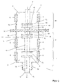
- FIG. 2 shows a vacuum interrupter 1 according to the invention with a first contact system I, a second contact system II and a third contact system III, which are all designed as vacuum switching sections.
- the contact systems I, II and III are each spatially separated in a separate vacuum interrupter chamber 2, 3 and 4, but arranged in a common, all contact systems I, II and III enclosing housing 5.
- In the lateral wall region of the individual vacuum interrupters 2, 3 and 4 each have a plurality of insulating ceramics 6 are provided.
- Centrally in extension of the rotationally symmetrical longitudinal axis s1 is an upper, fixed plunger 7 and at the opposite end a lower, movable plunger 8 is provided, which carry in the interior of the housing 5 in known manner each contact pieces 9 and 10.
- the contact piece 9 can be separately and independently brought by an operation of the movable plunger 8 with a fixed contact 11 in electrical connection.
- the fixed contact 11 is arranged on a provided in the interior of the housing 5 fixed, electrically conductive plunger 12, which penetrates the separation between the vacuum interrupters 3 and 4 in the extension of the longitudinal axis s1 and at its, the fixed contact 11, opposite end another fixed contact 13 has.
Landscapes
- Engineering & Computer Science (AREA)
- Power Engineering (AREA)
- High-Tension Arc-Extinguishing Switches Without Spraying Means (AREA)
- Housings And Mounting Of Transformers (AREA)
Description
- Die Erfindung betrifft einen Stufenschalter zur unterbrechungslosen Umschaltung zwischen Wicklungsanzapfungen eines Stufentransformators.
- Die vorliegende Erfindung betrifft weiterhin eine für einen solchen Stufenschalter besonders geeignete neuartige Vakuumschaltröhre.
- Aus der
DE 20 21 575 ist ein Stufenschalter bekannt, der insgesamt vier Vakuumschaltröhren pro Phase aufweist. In jedem der beiden Lastzweige sind jeweils eine Vakuumschaltröhre als Hauptkontakt und jeweils eine weitere Vakuumschaltröhre, in Reihenschaltung mit einem Überschaltwiderstand, als Widerstandskontakt vorgesehen. - Bei einer unterbrechungslosen Lastumschaltung von der bisherigen Wicklungsanzapfung n auf eine neue, vorgewählte Wicklungsanzapfung n+1 wird zunächst der Hauptkontakt der abschaltenden Seite geöffnet, darauf schließt der Widerstandskontakt der übernehmenden Seite, so dass zwischen den beiden Stufen n und n+1 ein durch die Überschaltwiderstände begrenzter Ausgleichsstrom fließt.
- Nachdem der bisher geschlossene Widerstandskontakt der abschaltenden Seite geöffnet hat, schließt dann der Hauptkontakt der übernehmenden Seite, so dass der gesamte Laststrom von der neuen Wicklungsanzapfung n+1 zur Lastableitung führt; die Umschaltung ist beendet.
- Bei verschiedenen Anwendungsfällen solcher bekannter Stufenschalter mit Vakuumschaltröhren zur Regelung von Leistungstransformatoren ist jedoch eine hohe Stoßspannungsfestigkeit, bis zu 100 kV und deutlich darüber hinaus, erforderlich. Solche unerwünschten Stoßspannungen, deren Höhe wesentlich durch den Aufbau des Stufentransformators und der Wicklungsteile zwischen den einzelnen Anzapfstufen bedingt ist, sind zum einen Blitzstoßspannungen, die sich durch das Einschlagen von Blitzen im Netz ergeben. Zum anderen können auch Schaltstoßspannungen auftreten, die durch nicht vorhersehbare Schaltstöße im zu regelnden Netz verursacht sind.
- Bei nicht ausreichender Stoßspannungsfestigkeit des Stufenschalters kann es zu einem kurzzeitigem Stufenkurzschluss kommen, falls die Vakuumschaltröhre im nicht den Laststrom führenden Lastzweig durchschlägt.
- Dies führt in vielen Fällen bei der Auslegung der Schaltstrecken und damit insbesondere auch der Vakuumschaltröhren zu einer Überdimensionierung, damit diese mit Sicherheit der beschriebenen Spannungsbeanspruchung standhalten. Sowohl der heute bei modernen Geräten zur Verfügung stehende geringe Bauraum, als auch die Wirtschaftlichkeit sowie Verfügbarkeit solcher Vakuumschaltröhren lassen eine solche Überdimensionierung nachteilig erscheinen.
- In der nicht vorveröffentlichten
DE 10 2010 024 255 wird daher ein Stufenschalter vorgeschlagen, bei dem eine erste Wicklungsanzapfung eines ersten Hauptstromzweiges über eine Reihenschaltung, bestehend aus einem ersten mechanischen Umschalter und einem ersten Schaltmittel, d. h. einer Vakuumschaltröhre oder alternativ einem Halbleiterbauelement, mit einer Lastableitung verbunden ist. In analog symmetrischer Bauweise dazu wird eine zweite Wicklungsanzapfung eines zweiten Hauptstromzweiges über eine Reihenschaltung, bestehend aus einem zweiten mechanischen Umschalter und einem zweiten Schaltmittel, d. h. einer zweiten Vakuumschaltröhre oder alternativ einem zweiten Halbleiterbauelement, ebenfalls mit der Lastableitung verbunden. Weiterhin ist zwischen der ersten Wicklungsanzapfung und dem ersten mechanischen Umschalter ein erster Hilfsstromzweig mit einem eingeschleiften Widerstand abgezweigt, mittels dem eine elektrische Verbindung mit dem zweiten mechanischen Umschalter des zweiten Hauptstromzweiges herstellbar ist und zwischen der zweiten Wicklungsanzapfung und dem zweiten mechanischen Umschalter ein zweiter Hilfsstromzweig mit einem weiteren eingeschleiften Widerstand abgezweigt ist, mittels dem eine elektrische Verbindung mit dem ersten mechanischen Umschalter des ersten Hauptstromzweiges herstellbar ist. - Mit anderen Worten: Es befindet sich also bei dem bekannten Stufenschalter in jedem Haupt- und Hilfsstromzweig ein mit der jeweiligen Vakuumschaltröhre in Reihe geschalteter mechanischer Umschalter, der eine vollständig galvanische Trennung der jeweils nicht beschalteten Wicklungsanzapfung, und damit eine hohe Stoßspannungsfestigkeit, sicherstellt.
- Alle aus dem Stand der Technik bekannten Stufenschalter benötigen mehrere Vakuumschaltröhren und zusätzliche mechanische Schaltmittel pro Phase, was auf Grund des hohen Platzbedarfs der einzelnen Schaltmittel und des damit einhergehenden konstruktiven und mechanischen Aufwandes nachteilig und vor allem teuer ist. Nicht zuletzt auch deshalb, weil für einen Umschaltvorgang eine Vielzahl von erforderlichen Einzelbauteilen in den Stufenschaltern zur Schaltsequenzrealisierung notwendig sind, die dann innerhalb nur weniger zehntel Sekunden in einem zeitlich exakt definierten Umschaltvorgang ineinandergreifen müssen.
- Aufgabe der vorliegenden Erfindung ist es daher, einen Stufenschalter zur unterbrechungslosen Umschaltung zwischen Wicklungsanzapfungen eines Stufentransformators anzugeben, der eine Reduzierung der Komplexität und der erforderlichen Einzelbauteile ermöglicht, dabei insbesondere mechanische Schaltmittel entbehrlich macht und zudem eine hohe Stoßspannungsfestigkeit aufweist. Weiterhin ist es Aufgabe der vorliegenden Erfindung, eine Vakuumschaltröhre anzugeben, die besonders vorteilhaft für einen solchen weiter entwickelten Stufenschalter verwendbar ist.
- Diese Aufgaben werden durch einen Stufenschalter mit den Merkmalen des ersten Patentanspruches sowie einer für einen solchen Stufenschalter besonders geeigneten Vakuumschaltröhre mit den Merkmalen des sechsten Patentanspruches gelöst. Die jeweiligen Unteransprüche betreffen dabei besonders bevorzugte Weiterbildungen der Erfindung.
- Dem erfindungsgemäßen Stufenschalter liegt die allgemeine Idee zugrunde, jeweils einen Hauptkontakt und ein seriell dazu geschaltetes mechanisches Schaltmittel eines ersten Lastzweiges und einen zusätzlichen Widerstandskontakt eines zweiten Lastzweiges in nur einer einzigen Vakuumschaltröhre mit einem gemeinsamen Gehäuse zu vereinen.
Der erfindungsgemäßen Vakuumschaltröhre liegt darüber hinaus die allgemeine erfinderische Idee zugrunde, durch die Kombination der Bauform einer Vakuumschaltröhre mit mehreren beweglichen Kontaktsystemen, die in separaten und gegenseitig abgedichteten Vakuumschaltkammern angeordnet sind, die Funktionalitäten von nach dem Stand der Technik zwei erforderlichen Vakuumschaltröhren und einem zusätzlichen mechanischen Schaltmittel durch eine einzige erfindungsgemäße Vakuumschaltröhre zu ersetzen. Mit andern Worten: Es werden bei der erfindungsgemäßen Vakuumschaltröhre die bisher separat erforderlichen Schaltmittel, nämlich die zwei unter Last schaltenden Vakuumschaltröhren und das eine weitere mechanische Schaltmittel, nicht mehr, wie nach dem Stand der Technik, als einzelne Baugruppen ausgeführt und in dem Stufenschalter verbaut, sondern in nun einer einzigen Vakuumschaltröhre mit in mehreren separaten Vakuumschaltkammern angeordneten Vakuumschaltstrecken zusammengefasst. Die Vakuumschaltröhre vermag es dabei sowohl das mechanische Schaltmittel eines Umschalters als auch eines mechanischen Ein-, Ausschalters nun funktional durch eine Vakuumschaltstrecke zu ersetzen. - Die dielektrische Festigkeit der neuartigen Vakuumschaltröhre wird dadurch erhöht, dass die einzelnen Vakuumschaltstrecken der mehreren Kontaktsysteme in getrennten, d. h. gegenseitig abgedichteten, Vakuumschaltkammern, jedoch in einem gemeinsamen Gehäuse, angeordnet sind. Mit anderen Worten: Die Gefahr vorhandener Potenzialunterschiede zwischen den verschiedenen Kontaktsystemen, die zu einem übergreifenden Lichtbogen führen könnten, werden erfindungsgemäß dadurch gelöst, dass mehrere separate Vakuumschaltkammern vorgesehen sind, in denen die Kontaktsysteme jeweils elektrisch untereinander gekoppelt sind.
- Vakuumschaltröhren mit zwei Kontaktstellen sind an sich bereits bekannt.
- Die
DE 3344367 betrifft eine Vakuumschaltröhre mit zwei elektrisch in Reihe geschalteten Kontaktpaaren in einem einzigen Vakuumraum, die gleichzeitig betätigbar sind. - Die
DE 197 56 308 C1 betrifft eine ähnliche Vakuumschaltröhre mit zwei auf einer gemeinsamen Achse angeordneten Schaltstrecken, wobei innenliegende Kontaktdruckfedern vorgesehen sind. - Die
EP 0 258 614 B1 beschreibt die Kombination einer Vakuumschaltröhre und einer spezifischen Beschaltung an einem Stufenschalter. Hierbei sind mehrere Schaltstrecken in einem Vakuumraum angeordnet, was einen komplizierten Aufbau der Vakuumschaltröhre mit ringförmigen Festkontakten bedingt. - Die
DE 10 2006 033 422 B3 schließlich beschreibt eine weitere Vakuumschaltröhre mit mehrfacher Funktionalität, wobei auch hier sowohl ringförmige Festkontakte als auch innenliegende Kontaktdruckfedern erforderlich sind. - Die Erfindung soll nachstehend an Hand von Figuren noch beispielhaft näher erläutert werden.
- Es zeigen:
- Figur 1
- einen Stufenschalter nach dem Stand der Technik
- Figur 2
- eine erfindungsgemäße Vakuumschaltröhre für einen Stufenschalter in einer schematischen Darstellung.
- In
Figur 1 ist ein aus dem Stand der Technik bekannter Stufenschalter gezeigt. Er weist einen ersten Lastzweig auf, in dem sich eine als Hauptkontakt wirkende Vakuumschaltröhre V1 und ein in Reihe dazu geschalteter mechanischer Umschalter U1 sowie parallel dazu ein Überschaltwiderstand R1 und eine als Widerstandskontakt wirkende Vakuumschaltröhre V2 befinden. Der zweite Lastzweig besitzt ganz analog eine Vakuumschaltröhre V4 und einen in Reihe dazu geschalteten mechanischen Umschalter U2 sowie parallel dazu einen weiteren Überschaltwiderstand R2 und eine als Widerstandkontakt wirkende Vakuumschaltröhre V3. Der bekannte Stufenschalter besitzt also zwei Vakuumschaltröhren pro Lastzweig, mithin vier Vakuumschaltröhren pro Phase. Die Ausgangslage, bei der die Anzapfung n beschaltet ist, entspricht der inFigur 1 dargestellten Stellung der einzelnen Schaltelemente. Die Umschaltung erfolgt in folgenden Schritten: - Vakuumschaltröhre V1
- Vakuumschaltröhre V3 schließt
- Vakuumschaltröhre V2 öffnet
- Vakuumschaltröhre V4 schließt; die Umschaltung ist abgeschlossen.
-
Figur 2 zeigt eine erfindungsgemäße Vakuumschaltröhre 1 mit einem ersten Kontaktsystem I, einem zweiten Kontaktsystem II und einem dritten Kontaktsystem III, die alle als Vakuumschaltstrecken ausgebildet sind. Zudem sind die Kontaktsysteme I, II und III jeweils räumlich getrennt in einer separaten Vakuumschaltkammer 2, 3 und 4, jedoch in einem gemeinsamen, alle Kontaktsysteme I, II und III umschließenden Gehäuse 5 angeordnet. Im seitlichen Wandungsbereich der einzelnen Vakuumschaltkammern 2, 3 und 4 sind jeweils mehrere Isolierkeramiken 6 vorgesehen. Zentrisch in Verlängerung der rotationssymmetrischen Längsachse s1 ist ein oberer, fester Stößel 7 und am entgegengesetzten Ende ein unterer, beweglicher Stößel 8 vorgesehen, die im Inneren des Gehäuses 5 auf an sich bekannte Weise jeweils Kontaktstücke 9 und 10 tragen. Das Kontaktstück 9 kann separat und unabhängig durch eine Betätigung des beweglichen Stößels 8 mit einem festen Kontakt 11 elektrisch in Verbindung gebracht werden. Der feste Kontakt 11 ist dabei an einem im Inneren des Gehäuses 5 vorgesehenen festen, elektrisch leitenden Stößel 12 angeordnet, der die Abtrennung zwischen der Vakuumschaltkammer 3 und 4 in Verlängerung der Längsachse s1 durchdringt und an seinem, dem festen Kontakt 11, gegenüberliegenden Ende einen weiteren festen Kontakt 13 aufweist. Die dichte Abtrennung zwischen den Vakuumschaltkammern 2 und 3 wird durch eine in Längsrichtung der Achse s1 verschiebbar ausgebildete, elektrisch leitende Platte 14 sichergestellt, an der zu beiden Seiten hin ein weiteres festes Kontaktstück 15 und 16 über jeweils einen elektrisch leitenden Steg 17 und 18 befestigt ist. Damit kann durch vertikales Verschieben der Platte 14 der feste Kontakte 16 mit dem festen Kontakt 10 beschaltet werden oder der feste Kontakt 15 mit dem festen Kontakt 13. Im Bereich der Wandung des Gehäuses 5 sind hier nach dem Stand der Technik bekannte Faltenbalge 19 vorgesehen, die der Platte 14 eine vertikale Bewegungsfreiheit einräumen. Die bekannten Kontaktfedern, die mit dem Stößel 8 zusammenwirken, sind hier aus Übersichtlichkeitsgründen nicht dargestellt. - Spiegelt man die in
Figur 2 beschriebene Vakuumschaltröhre 1 auf einen Stufenschalter derFigur 1 , so werden erfindungsgemäß die beiden bisher separaten Schaltelemente V1, V3 und U1 bzw. V2, V4 und U2 in nun einer einzigen Vakuumschaltröhre 1 mit den getrennt steuerbaren Kontaktsystemen I, II und III zusammengefasst. Wird der Stößel 7 der inFigur 2 abgebildeten Vakuumschaltröhre 1 über einen Widerstand R2 mit der Wicklungsanzapfung n+1, die elektrisch leitende Platte 14 mit der Lastableitung LA und der untere Stößel 8 mit der Wicklungsanzapfung n elektrisch leitend verbunden, so lässt sich dadurch der inFigur 1 beschriebene Stufenschalter besonders einfach mechanisch realisieren.
Claims (10)
- Stufenschalter mit Vakuumschaltröhren zur unterbrechungslosen Umschaltung zwischen Wicklungsanzapfungen eines Stufentransformators,
wobei für jede zu schaltende Phase zwei Lastzweige vorgesehen sind,
wobei jeder Lastzweig einen als Hauptkontakt wirkenden Vakuumschaltkontakt (V1,V4) und ein in Reihe dazu schaltbares mechanisches Schaltmittel (U1,U2) aufweist,
wobei für jede zu schaltende Phase ein dem entsprechenden Lastzweig parallel schaltbarer Hilfsstromzweig vorgesehen ist,
wobei jeder Hilfsstromzweig wenigstens einen Überschaltwiderstand (R1,R2) und in Serie einen als Hilfskontakt wirkenden weiteren Vakuumschaltkontakt (V2,V3) aufweist und wobei sowohl die Lastzweige als auch die Hilfsstromzweige beider Lastzweige mit einer gemeinsamen Lastableitung verbunden sind,
dadurch gekennzeichnet,
dass der als Hauptkontakt wirkende Vakuumschaltkontakt (V1) des ersten Lastzweiges und das in Reihe dazu angeordnete mechanische Schaltmittel (U1) des ersten Lastzweiges und der als Hilfskontakt wirkende Vakuumschaltkontakt (V3) des zweiten Lastzweiges baulich in einer einzigen Vakuumschaltröhre (1) mit einem gemeinsamen Gehäuse (5) vereinigt sind,
dass der als Hauptkontakt wirkende Vakuumschaltkontakt (V4) des zweiten Lastzweiges und das in Reihe dazu angeordnete mechanische Schaltmittel (U2) des zweiten Lastzweiges und der als Hilfskontakt wirkende Vakuumschaltkontakt (V2) des ersten Lastzweiges in einer weiteren einzigen Vakuumschaltröhre (1) mit einem gemeinsamen Gehäuse (5) vereinigt sind,
und dass jeweils innerhalb des gemeinsamen Gehäuses (5) der einen Vakuumschaltröhre und der weiteren Vakuumschaltröhre für jeden Vakuumschaltkontakt (V1, V3; V2, V4) sowie für jedes mechanische Schaltmittel (U1; U2) jeweils eine getrennte, gegenseitig abgedichtete Vakuumschaltkammer (2, 3 und 4) vorgesehen ist. - Stufenschalter nach Anspruch 1,
dadurch gekennzeichnet,
dass die in den separaten Vakuumschaltkammern (2, 3 und 4) vorgesehenen Vakuumschaltkontakte (V1...V4) und das weitere mechanische Schaltmittel (U1, U2) jeweils ein separates Kontaktsystem (I,II,III) bilden. - Stufenschalter nach Anspruch 1 oder 2,
dadurch gekennzeichnet,
dass das erste Kontaktsystem (I) das mechanische Schaltmittel (U1 oder U2) bildet. - Stufenschalter nach einem der Ansprüche 1 bis 3,
dadurch gekennzeichnet,
dass das zweite Kontaktsystem (II) den Vakuumschaltkontakt (V1 oder V4) bildet. - Stufenschalter nach einem der Ansprüche 1 bis 4,
dadurch gekennzeichnet,
dass das dritte Kontaktsystem (III) den Vakuumschaltkontakt (V2 oder V3) bildet. - Vakuumschaltröhre für einen Stufenschalter nach den Ansprüchen 1 bis 5,
dadurch gekennzeichnet,
dass ein gemeinsames, die gesamte Vakuumschaltröhre (1) umschließendes Gehäuse (5) vorgesehen ist,
dass innerhalb des Gehäuses (5) mehrere, entlang einer gemeinsamen Längsachse (S1) angeordnete,
Kontaktsysteme (I, II und III) vorgesehen sind, die jeweils räumlich und luftdicht getrennt in einer separaten Vakuumschaltkammer (2, 3 und 4) angeordnet sind, - Vakuumschaltröhre nach Anspruch 6,
dadurch gekennzeichnet,
dass das erste Kontaktsystem (I) einen unteren, entlang der Längsachse (S1) bewegbaren, Stößel (8)
aufweist, an dem ein Kontaktstück (9) befestigt ist, das mit einem an einem festen Stößel (12) befestigten Kontaktstück (12) kontaktierbar ist. - Vakuumschaltröhre nach einem der Ansprüche 6 oder 7,
dadurch gekennzeichnet,
dass das zweite Kontaktsystem II einen, an dem gegenüberliegenden Ende des Kontaktstücks (12), ebenfalls an dem Stößel (12) befestigten Kontakt (13) aufweist, der mit einem, über einen Steg (17) an einer entlang der Längsachse (S1) verschiebbaren elektrisch leitenden Platte (14) befestigten Kontaktstück (15) kontaktierbar ist. - Vakuumschaltröhre nach einem der Ansprüche 6 bis 8,
dadurch gekennzeichnet,
dass das dritte Kontaktsystem (III) ein an einem oberen festen Stößel (7) befestigtes Kontaktstück (10) aufweist, das mit einem, über einen Steg (18) an der entlang der Längsachse (S1) verschiebbaren elektrisch leitenden Platte (14) befestigten Kontaktstück (16) kontaktierbar ist. - Vakuumschaltröhre nach einem der Ansprüche 7 bis 9,
dadurch gekennzeichnet,
dass in jeder Vakuumschaltkammer (2, 3 und 4) im Bereich der seitlichen Wandung des Gehäuses (5) mehrere Isolierkeramiken (6) vorgesehen sind.
Applications Claiming Priority (2)
| Application Number | Priority Date | Filing Date | Title |
|---|---|---|---|
| DE102011015922 | 2011-04-02 | ||
| PCT/EP2012/053587 WO2012136423A1 (de) | 2011-04-02 | 2012-03-02 | Stufenschalter und vakuumschaltröhre für einen solchen stufenschalter |
Publications (2)
| Publication Number | Publication Date |
|---|---|
| EP2695177A1 EP2695177A1 (de) | 2014-02-12 |
| EP2695177B1 true EP2695177B1 (de) | 2016-05-18 |
Family
ID=45808882
Family Applications (1)
| Application Number | Title | Priority Date | Filing Date |
|---|---|---|---|
| EP12707541.4A Active EP2695177B1 (de) | 2011-04-02 | 2012-03-02 | Stufenschalter und vakuumschaltröhre für einen solchen stufenschalter |
Country Status (8)
| Country | Link |
|---|---|
| US (1) | US8947188B2 (de) |
| EP (1) | EP2695177B1 (de) |
| JP (1) | JP2014514748A (de) |
| KR (1) | KR20140009389A (de) |
| CN (1) | CN103460324B (de) |
| BR (1) | BR112013022214A2 (de) |
| ES (1) | ES2586983T3 (de) |
| WO (1) | WO2012136423A1 (de) |
Families Citing this family (24)
| Publication number | Priority date | Publication date | Assignee | Title |
|---|---|---|---|---|
| DE102012107446B4 (de) * | 2012-08-14 | 2015-12-31 | Maschinenfabrik Reinhausen Gmbh | Lastumschalter, Laststufenschalter und Verfahren zum Umschalten eines Laststufenschalters |
| DE102013107558A1 (de) * | 2013-07-16 | 2015-01-22 | Maschinenfabrik Reinhausen Gmbh | Laststufenschalter |
| DE102013107552B4 (de) * | 2013-07-16 | 2017-03-16 | Maschinenfabrik Reinhausen Gmbh | Laststufenschalter |
| CN105580100B (zh) * | 2013-08-27 | 2017-12-12 | 赖茵豪森机械制造公司 | 有载分接开关、用于电压调节的可调式变压器和用于在可调式变压器中实施转换的方法 |
| CN105719891B8 (zh) * | 2013-11-27 | 2019-04-16 | 乐清市川嘉电气科技有限公司 | 提升绝缘性能的真空开关管 |
| CN105895442A (zh) * | 2013-11-27 | 2016-08-24 | 赵牧青 | 提升绝缘性能的真空开关管 |
| CN105742113B8 (zh) * | 2013-11-27 | 2019-04-19 | 乐清市川嘉电气科技有限公司 | 一种真空开关管 |
| CN105742112B8 (zh) * | 2013-11-27 | 2019-04-12 | 乐清市川嘉电气科技有限公司 | 一种具有较好缓冲作用的真空开关管 |
| CN105742111B8 (zh) * | 2013-11-27 | 2019-04-12 | 乐清市川嘉电气科技有限公司 | 提升电场分布均匀性的真空开关管 |
| CN105762003B8 (zh) * | 2013-11-27 | 2019-03-22 | 乐清市川嘉电气科技有限公司 | 一种提升绝缘性能的真空开关管 |
| DE102015102727A1 (de) * | 2015-02-25 | 2016-08-25 | Maschinenfabrik Reinhausen Gmbh | Verfahren zum Ändern der aktiven Windungszahl einer Regelwicklung in einer elektrischen Anlage und elektrische Anlage mit einer Regelwicklung |
| DE102015106178A1 (de) * | 2015-04-22 | 2016-10-27 | Maschinenfabrik Reinhausen Gmbh | Laststufenschalter |
| KR101883432B1 (ko) * | 2016-06-28 | 2018-08-24 | 인텍전기전자 주식회사 | 보조스위치 일체형 진공차단기 |
| CN105957770B (zh) * | 2016-07-15 | 2018-08-07 | 江苏现代电力科技股份有限公司 | 分级开合的高压真空灭弧室 |
| CN107968015B (zh) * | 2017-03-31 | 2021-01-05 | 天津市先智电气设备有限公司 | 固封极柱及双电源转换开关 |
| DE102017112813A1 (de) * | 2017-06-11 | 2018-12-13 | Eaton Electrical Ip Gmbh & Co. Kg | Doppelkontakt-Schalter mit Vakuumschaltkammern |
| GB2565085B (en) * | 2017-07-31 | 2020-05-20 | Camlin Tech Limited | Improved Vacuum Circuit Breaker |
| CN110416020B (zh) * | 2018-04-26 | 2025-05-09 | 赛雪龙公司 | 开关装置 |
| EP3745434B1 (de) | 2019-05-28 | 2023-05-17 | Hitachi Energy Switzerland AG | Druckimpulsdiagnose eines laststufenschalters |
| CN111799075B (zh) * | 2020-06-24 | 2025-02-07 | 中国电力科学研究院有限公司 | 一种真空有载分接开关双电阻过渡电路及调压方法 |
| CN111986902B (zh) * | 2020-06-24 | 2025-02-07 | 中国电力科学研究院有限公司 | 一种带隔离触头的真空有载分接开关过渡电路及调压方法 |
| CN111799076B (zh) * | 2020-06-24 | 2025-02-07 | 中国电力科学研究院有限公司 | 一种真空有载分接开关单电阻交替型过渡电路及调压方法 |
| KR102219309B1 (ko) | 2020-11-13 | 2021-02-24 | 한국에너지솔루션 주식회사 | 스마트 oltc 배전용 변압기 |
| WO2023041961A1 (zh) * | 2021-09-20 | 2023-03-23 | 郑宇程 | 一种接触器 |
Family Cites Families (16)
| Publication number | Priority date | Publication date | Assignee | Title |
|---|---|---|---|---|
| US3405245A (en) | 1964-05-29 | 1968-10-08 | Mitsubishi Electric Corp | Multiple-break vacuum-type circuit interrupters |
| JPS507727B1 (de) * | 1969-11-04 | 1975-03-28 | ||
| US3819892A (en) * | 1972-11-30 | 1974-06-25 | Gen Electric | Fail safe vacuum type circuit interrupter and associated load current tap changer for electric induction apparatus |
| DE3344376A1 (de) * | 1983-12-08 | 1985-06-13 | Licentia Patent-Verwaltungs-Gmbh, 6000 Frankfurt | Vakuumschalter |
| DE3772904D1 (de) | 1986-08-06 | 1991-10-17 | Reinhausen Maschf Scheubeck | Stufenschalteinrichtung fuer transformatoren. |
| DE4021945C2 (de) * | 1990-07-10 | 1999-12-30 | Alstom Sachsenwerk Gmbh | Schaltvorrichtung zur Unterbrechung von Fehlerströmen |
| DE19756308C1 (de) | 1997-12-12 | 1999-03-25 | Siemens Ag | Vakuumschalter, insbesondere für Hochspannung |
| DE10102310C1 (de) * | 2001-01-18 | 2002-06-20 | Reinhausen Maschf Scheubeck | Thyristor-Stufenschalter |
| JP4136421B2 (ja) * | 2002-03-29 | 2008-08-20 | 株式会社高岳製作所 | 負荷時タップ切換器 |
| JP2004152639A (ja) * | 2002-10-31 | 2004-05-27 | Toshiba Corp | 真空開閉装置 |
| DE112005003757A5 (de) * | 2005-09-12 | 2008-08-14 | Siemens Aktiengesellschaft | Vakuumschaltröhre |
| DE102006033422B3 (de) | 2006-07-19 | 2007-11-08 | Maschinenfabrik Reinhausen Gmbh | Vakuumschaltröhre |
| BRPI0715709B8 (pt) * | 2006-08-23 | 2022-12-13 | Abb Technology Ltd | Comutador de desvio |
| FR2927194B1 (fr) * | 2008-01-31 | 2010-02-19 | Schneider Electric Ind Sas | Ampoule a vide pour un appareil electrique de coupure assurant au moins la fonction sectionneur |
| DE202010017377U1 (de) | 2010-06-18 | 2012-01-03 | Maschinenfabrik Reinhausen Gmbh | Laststufenschalter |
| DE102011008959B9 (de) * | 2011-01-19 | 2012-04-26 | Maschinenfabrik Reinhausen Gmbh | Stufenschalter mit Vakuumschaltröhren |
-
2012
- 2012-03-02 US US14/000,435 patent/US8947188B2/en not_active Expired - Fee Related
- 2012-03-02 JP JP2014501511A patent/JP2014514748A/ja active Pending
- 2012-03-02 EP EP12707541.4A patent/EP2695177B1/de active Active
- 2012-03-02 KR KR1020137024799A patent/KR20140009389A/ko not_active Ceased
- 2012-03-02 BR BR112013022214A patent/BR112013022214A2/pt not_active IP Right Cessation
- 2012-03-02 CN CN201280015618.4A patent/CN103460324B/zh not_active Expired - Fee Related
- 2012-03-02 WO PCT/EP2012/053587 patent/WO2012136423A1/de not_active Ceased
- 2012-03-02 ES ES12707541.4T patent/ES2586983T3/es active Active
Also Published As
| Publication number | Publication date |
|---|---|
| KR20140009389A (ko) | 2014-01-22 |
| EP2695177A1 (de) | 2014-02-12 |
| WO2012136423A1 (de) | 2012-10-11 |
| JP2014514748A (ja) | 2014-06-19 |
| US8947188B2 (en) | 2015-02-03 |
| BR112013022214A2 (pt) | 2017-05-23 |
| ES2586983T3 (es) | 2016-10-19 |
| CN103460324A (zh) | 2013-12-18 |
| HK1189707A1 (zh) | 2014-06-13 |
| CN103460324B (zh) | 2016-03-02 |
| US20140085028A1 (en) | 2014-03-27 |
Similar Documents
| Publication | Publication Date | Title |
|---|---|---|
| WO2012136423A1 (de) | Stufenschalter und vakuumschaltröhre für einen solchen stufenschalter | |
| EP2666173B1 (de) | Stufenschalter mit vakuumschaltröhren | |
| EP2569781B1 (de) | Laststufenschalter | |
| EP2486577B1 (de) | Stufenschalter | |
| EP2617048B1 (de) | Stufenschalter und vakuumschaltröhre für einen solchen stufenschalter | |
| EP2583289B1 (de) | Laststufenschalter | |
| EP2569782B1 (de) | Laststufenschalter | |
| EP2647022B1 (de) | Stufenschalter und vakuumschaltröhre für einen solchen stufenschalter | |
| EP2638553B1 (de) | Stufenschalter | |
| EP2534663A1 (de) | Stufenschalter mit freilaufelement | |
| EP3146540A1 (de) | Schaltanordnung für einen stufentransformator sowie verfahren zum betreiben einer derartigen schaltanordnung | |
| DE102013110652B4 (de) | Schaltanordnung mit Vorwähler | |
| WO2016034438A1 (de) | Schaltanordnung für einen regeltransformator, insbesondere vorwähler | |
| EP1881510A1 (de) | Vakuumschaltröhre | |
| DE102010007534A1 (de) | Stufenschalter | |
| EP2586049A1 (de) | Stufenschalter |
Legal Events
| Date | Code | Title | Description |
|---|---|---|---|
| PUAI | Public reference made under article 153(3) epc to a published international application that has entered the european phase |
Free format text: ORIGINAL CODE: 0009012 |
|
| 17P | Request for examination filed |
Effective date: 20131104 |
|
| AK | Designated contracting states |
Kind code of ref document: A1 Designated state(s): AL AT BE BG CH CY CZ DE DK EE ES FI FR GB GR HR HU IE IS IT LI LT LU LV MC MK MT NL NO PL PT RO RS SE SI SK SM TR |
|
| REG | Reference to a national code |
Ref country code: HK Ref legal event code: DE Ref document number: 1189707 Country of ref document: HK |
|
| DAX | Request for extension of the european patent (deleted) | ||
| GRAP | Despatch of communication of intention to grant a patent |
Free format text: ORIGINAL CODE: EPIDOSNIGR1 |
|
| RIC1 | Information provided on ipc code assigned before grant |
Ipc: H01H 33/16 20060101ALN20151118BHEP Ipc: H01H 33/664 20060101ALI20151118BHEP Ipc: H01H 33/666 20060101ALN20151118BHEP Ipc: H01H 9/00 20060101AFI20151118BHEP Ipc: H01F 29/04 20060101ALI20151118BHEP |
|
| RIC1 | Information provided on ipc code assigned before grant |
Ipc: H01H 33/16 20060101ALN20151123BHEP Ipc: H01F 29/04 20060101ALI20151123BHEP Ipc: H01H 33/666 20060101ALN20151123BHEP Ipc: H01H 9/00 20060101AFI20151123BHEP Ipc: H01H 33/664 20060101ALI20151123BHEP |
|
| INTG | Intention to grant announced |
Effective date: 20151208 |
|
| GRAS | Grant fee paid |
Free format text: ORIGINAL CODE: EPIDOSNIGR3 |
|
| GRAA | (expected) grant |
Free format text: ORIGINAL CODE: 0009210 |
|
| AK | Designated contracting states |
Kind code of ref document: B1 Designated state(s): AL AT BE BG CH CY CZ DE DK EE ES FI FR GB GR HR HU IE IS IT LI LT LU LV MC MK MT NL NO PL PT RO RS SE SI SK SM TR |
|
| REG | Reference to a national code |
Ref country code: GB Ref legal event code: FG4D Free format text: NOT ENGLISH |
|
| REG | Reference to a national code |
Ref country code: CH Ref legal event code: EP |
|
| REG | Reference to a national code |
Ref country code: IE Ref legal event code: FG4D Free format text: LANGUAGE OF EP DOCUMENT: GERMAN Ref country code: AT Ref legal event code: REF Ref document number: 801113 Country of ref document: AT Kind code of ref document: T Effective date: 20160615 |
|
| REG | Reference to a national code |
Ref country code: DE Ref legal event code: R096 Ref document number: 502012007134 Country of ref document: DE |
|
| REG | Reference to a national code |
Ref country code: CH Ref legal event code: NV Representative=s name: SIEMENS SCHWEIZ AG, CH Ref country code: CH Ref legal event code: PUEA Owner name: SIEMENS AKTIENGESELLSCHAFT, DE Free format text: FORMER OWNER: SIEMENS AKTIENGESELLSCHAFT, DE |
|
| REG | Reference to a national code |
Ref country code: NL Ref legal event code: MP Effective date: 20160518 |
|
| REG | Reference to a national code |
Ref country code: LT Ref legal event code: MG4D |
|
| RAP2 | Party data changed (patent owner data changed or rights of a patent transferred) |
Owner name: SIEMENS AG |
|
| REG | Reference to a national code |
Ref country code: ES Ref legal event code: FG2A Ref document number: 2586983 Country of ref document: ES Kind code of ref document: T3 Effective date: 20161019 |
|
| PG25 | Lapsed in a contracting state [announced via postgrant information from national office to epo] |
Ref country code: FI Free format text: LAPSE BECAUSE OF FAILURE TO SUBMIT A TRANSLATION OF THE DESCRIPTION OR TO PAY THE FEE WITHIN THE PRESCRIBED TIME-LIMIT Effective date: 20160518 Ref country code: NL Free format text: LAPSE BECAUSE OF FAILURE TO SUBMIT A TRANSLATION OF THE DESCRIPTION OR TO PAY THE FEE WITHIN THE PRESCRIBED TIME-LIMIT Effective date: 20160518 Ref country code: NO Free format text: LAPSE BECAUSE OF FAILURE TO SUBMIT A TRANSLATION OF THE DESCRIPTION OR TO PAY THE FEE WITHIN THE PRESCRIBED TIME-LIMIT Effective date: 20160818 Ref country code: LT Free format text: LAPSE BECAUSE OF FAILURE TO SUBMIT A TRANSLATION OF THE DESCRIPTION OR TO PAY THE FEE WITHIN THE PRESCRIBED TIME-LIMIT Effective date: 20160518 |
|
| PG25 | Lapsed in a contracting state [announced via postgrant information from national office to epo] |
Ref country code: LV Free format text: LAPSE BECAUSE OF FAILURE TO SUBMIT A TRANSLATION OF THE DESCRIPTION OR TO PAY THE FEE WITHIN THE PRESCRIBED TIME-LIMIT Effective date: 20160518 Ref country code: PT Free format text: LAPSE BECAUSE OF FAILURE TO SUBMIT A TRANSLATION OF THE DESCRIPTION OR TO PAY THE FEE WITHIN THE PRESCRIBED TIME-LIMIT Effective date: 20160919 Ref country code: RS Free format text: LAPSE BECAUSE OF FAILURE TO SUBMIT A TRANSLATION OF THE DESCRIPTION OR TO PAY THE FEE WITHIN THE PRESCRIBED TIME-LIMIT Effective date: 20160518 Ref country code: GR Free format text: LAPSE BECAUSE OF FAILURE TO SUBMIT A TRANSLATION OF THE DESCRIPTION OR TO PAY THE FEE WITHIN THE PRESCRIBED TIME-LIMIT Effective date: 20160819 Ref country code: HR Free format text: LAPSE BECAUSE OF FAILURE TO SUBMIT A TRANSLATION OF THE DESCRIPTION OR TO PAY THE FEE WITHIN THE PRESCRIBED TIME-LIMIT Effective date: 20160518 Ref country code: SE Free format text: LAPSE BECAUSE OF FAILURE TO SUBMIT A TRANSLATION OF THE DESCRIPTION OR TO PAY THE FEE WITHIN THE PRESCRIBED TIME-LIMIT Effective date: 20160518 |
|
| REG | Reference to a national code |
Ref country code: FR Ref legal event code: TP Owner name: SIEMENS AG, DE Effective date: 20161028 |
|
| PG25 | Lapsed in a contracting state [announced via postgrant information from national office to epo] |
Ref country code: CZ Free format text: LAPSE BECAUSE OF FAILURE TO SUBMIT A TRANSLATION OF THE DESCRIPTION OR TO PAY THE FEE WITHIN THE PRESCRIBED TIME-LIMIT Effective date: 20160518 Ref country code: EE Free format text: LAPSE BECAUSE OF FAILURE TO SUBMIT A TRANSLATION OF THE DESCRIPTION OR TO PAY THE FEE WITHIN THE PRESCRIBED TIME-LIMIT Effective date: 20160518 Ref country code: DK Free format text: LAPSE BECAUSE OF FAILURE TO SUBMIT A TRANSLATION OF THE DESCRIPTION OR TO PAY THE FEE WITHIN THE PRESCRIBED TIME-LIMIT Effective date: 20160518 Ref country code: SK Free format text: LAPSE BECAUSE OF FAILURE TO SUBMIT A TRANSLATION OF THE DESCRIPTION OR TO PAY THE FEE WITHIN THE PRESCRIBED TIME-LIMIT Effective date: 20160518 Ref country code: RO Free format text: LAPSE BECAUSE OF FAILURE TO SUBMIT A TRANSLATION OF THE DESCRIPTION OR TO PAY THE FEE WITHIN THE PRESCRIBED TIME-LIMIT Effective date: 20160518 |
|
| REG | Reference to a national code |
Ref country code: HK Ref legal event code: GR Ref document number: 1189707 Country of ref document: HK |
|
| REG | Reference to a national code |
Ref country code: DE Ref legal event code: R097 Ref document number: 502012007134 Country of ref document: DE |
|
| PG25 | Lapsed in a contracting state [announced via postgrant information from national office to epo] |
Ref country code: SM Free format text: LAPSE BECAUSE OF FAILURE TO SUBMIT A TRANSLATION OF THE DESCRIPTION OR TO PAY THE FEE WITHIN THE PRESCRIBED TIME-LIMIT Effective date: 20160518 Ref country code: PL Free format text: LAPSE BECAUSE OF FAILURE TO SUBMIT A TRANSLATION OF THE DESCRIPTION OR TO PAY THE FEE WITHIN THE PRESCRIBED TIME-LIMIT Effective date: 20160518 |
|
| REG | Reference to a national code |
Ref country code: FR Ref legal event code: PLFP Year of fee payment: 6 |
|
| PLBE | No opposition filed within time limit |
Free format text: ORIGINAL CODE: 0009261 |
|
| STAA | Information on the status of an ep patent application or granted ep patent |
Free format text: STATUS: NO OPPOSITION FILED WITHIN TIME LIMIT |
|
| 26N | No opposition filed |
Effective date: 20170221 |
|
| PG25 | Lapsed in a contracting state [announced via postgrant information from national office to epo] |
Ref country code: SI Free format text: LAPSE BECAUSE OF FAILURE TO SUBMIT A TRANSLATION OF THE DESCRIPTION OR TO PAY THE FEE WITHIN THE PRESCRIBED TIME-LIMIT Effective date: 20160518 |
|
| PGFP | Annual fee paid to national office [announced via postgrant information from national office to epo] |
Ref country code: IT Payment date: 20170329 Year of fee payment: 6 |
|
| PGFP | Annual fee paid to national office [announced via postgrant information from national office to epo] |
Ref country code: ES Payment date: 20170426 Year of fee payment: 6 |
|
| REG | Reference to a national code |
Ref country code: CH Ref legal event code: PCOW Free format text: NEW ADDRESS: WERNER-VON-SIEMENS-STRASSE 1, 80333 MUENCHEN (DE) |
|
| GBPC | Gb: european patent ceased through non-payment of renewal fee |
Effective date: 20170302 |
|
| PG25 | Lapsed in a contracting state [announced via postgrant information from national office to epo] |
Ref country code: MC Free format text: LAPSE BECAUSE OF FAILURE TO SUBMIT A TRANSLATION OF THE DESCRIPTION OR TO PAY THE FEE WITHIN THE PRESCRIBED TIME-LIMIT Effective date: 20160518 |
|
| REG | Reference to a national code |
Ref country code: IE Ref legal event code: MM4A |
|
| PG25 | Lapsed in a contracting state [announced via postgrant information from national office to epo] |
Ref country code: LU Free format text: LAPSE BECAUSE OF NON-PAYMENT OF DUE FEES Effective date: 20170302 |
|
| PG25 | Lapsed in a contracting state [announced via postgrant information from national office to epo] |
Ref country code: IE Free format text: LAPSE BECAUSE OF NON-PAYMENT OF DUE FEES Effective date: 20170302 Ref country code: GB Free format text: LAPSE BECAUSE OF NON-PAYMENT OF DUE FEES Effective date: 20170302 |
|
| REG | Reference to a national code |
Ref country code: BE Ref legal event code: MM Effective date: 20170331 |
|
| REG | Reference to a national code |
Ref country code: FR Ref legal event code: PLFP Year of fee payment: 7 |
|
| REG | Reference to a national code |
Ref country code: AT Ref legal event code: MM01 Ref document number: 801113 Country of ref document: AT Kind code of ref document: T Effective date: 20170302 |
|
| PG25 | Lapsed in a contracting state [announced via postgrant information from national office to epo] |
Ref country code: BE Free format text: LAPSE BECAUSE OF NON-PAYMENT OF DUE FEES Effective date: 20170331 |
|
| PG25 | Lapsed in a contracting state [announced via postgrant information from national office to epo] |
Ref country code: AT Free format text: LAPSE BECAUSE OF NON-PAYMENT OF DUE FEES Effective date: 20170302 |
|
| PG25 | Lapsed in a contracting state [announced via postgrant information from national office to epo] |
Ref country code: MT Free format text: LAPSE BECAUSE OF FAILURE TO SUBMIT A TRANSLATION OF THE DESCRIPTION OR TO PAY THE FEE WITHIN THE PRESCRIBED TIME-LIMIT Effective date: 20160518 |
|
| PG25 | Lapsed in a contracting state [announced via postgrant information from national office to epo] |
Ref country code: AL Free format text: LAPSE BECAUSE OF FAILURE TO SUBMIT A TRANSLATION OF THE DESCRIPTION OR TO PAY THE FEE WITHIN THE PRESCRIBED TIME-LIMIT Effective date: 20160518 |
|
| PG25 | Lapsed in a contracting state [announced via postgrant information from national office to epo] |
Ref country code: IT Free format text: LAPSE BECAUSE OF NON-PAYMENT OF DUE FEES Effective date: 20180302 |
|
| PG25 | Lapsed in a contracting state [announced via postgrant information from national office to epo] |
Ref country code: HU Free format text: LAPSE BECAUSE OF FAILURE TO SUBMIT A TRANSLATION OF THE DESCRIPTION OR TO PAY THE FEE WITHIN THE PRESCRIBED TIME-LIMIT; INVALID AB INITIO Effective date: 20120302 |
|
| PG25 | Lapsed in a contracting state [announced via postgrant information from national office to epo] |
Ref country code: BG Free format text: LAPSE BECAUSE OF FAILURE TO SUBMIT A TRANSLATION OF THE DESCRIPTION OR TO PAY THE FEE WITHIN THE PRESCRIBED TIME-LIMIT Effective date: 20160518 |
|
| REG | Reference to a national code |
Ref country code: ES Ref legal event code: FD2A Effective date: 20190903 |
|
| PG25 | Lapsed in a contracting state [announced via postgrant information from national office to epo] |
Ref country code: ES Free format text: LAPSE BECAUSE OF NON-PAYMENT OF DUE FEES Effective date: 20180303 Ref country code: CY Free format text: LAPSE BECAUSE OF NON-PAYMENT OF DUE FEES Effective date: 20160518 |
|
| PG25 | Lapsed in a contracting state [announced via postgrant information from national office to epo] |
Ref country code: MK Free format text: LAPSE BECAUSE OF FAILURE TO SUBMIT A TRANSLATION OF THE DESCRIPTION OR TO PAY THE FEE WITHIN THE PRESCRIBED TIME-LIMIT Effective date: 20160518 |
|
| PG25 | Lapsed in a contracting state [announced via postgrant information from national office to epo] |
Ref country code: TR Free format text: LAPSE BECAUSE OF FAILURE TO SUBMIT A TRANSLATION OF THE DESCRIPTION OR TO PAY THE FEE WITHIN THE PRESCRIBED TIME-LIMIT Effective date: 20160518 |
|
| PG25 | Lapsed in a contracting state [announced via postgrant information from national office to epo] |
Ref country code: IS Free format text: LAPSE BECAUSE OF FAILURE TO SUBMIT A TRANSLATION OF THE DESCRIPTION OR TO PAY THE FEE WITHIN THE PRESCRIBED TIME-LIMIT Effective date: 20160918 |
|
| PGFP | Annual fee paid to national office [announced via postgrant information from national office to epo] |
Ref country code: CH Payment date: 20210602 Year of fee payment: 10 |
|
| PGFP | Annual fee paid to national office [announced via postgrant information from national office to epo] |
Ref country code: FR Payment date: 20220324 Year of fee payment: 11 |
|
| REG | Reference to a national code |
Ref country code: CH Ref legal event code: PL |
|
| PG25 | Lapsed in a contracting state [announced via postgrant information from national office to epo] |
Ref country code: LI Free format text: LAPSE BECAUSE OF NON-PAYMENT OF DUE FEES Effective date: 20220331 Ref country code: CH Free format text: LAPSE BECAUSE OF NON-PAYMENT OF DUE FEES Effective date: 20220331 |
|
| PG25 | Lapsed in a contracting state [announced via postgrant information from national office to epo] |
Ref country code: FR Free format text: LAPSE BECAUSE OF NON-PAYMENT OF DUE FEES Effective date: 20230331 |
|
| PGFP | Annual fee paid to national office [announced via postgrant information from national office to epo] |
Ref country code: DE Payment date: 20250520 Year of fee payment: 14 |