EP2694748B1 - Verfahren zur herstellung einer schalenförmigen struktur, strukturelement und struktur - Google Patents
Verfahren zur herstellung einer schalenförmigen struktur, strukturelement und struktur Download PDFInfo
- Publication number
- EP2694748B1 EP2694748B1 EP12712387.5A EP12712387A EP2694748B1 EP 2694748 B1 EP2694748 B1 EP 2694748B1 EP 12712387 A EP12712387 A EP 12712387A EP 2694748 B1 EP2694748 B1 EP 2694748B1
- Authority
- EP
- European Patent Office
- Prior art keywords
- elements
- torus
- structural elements
- structural
- filling
- Prior art date
- Legal status (The legal status is an assumption and is not a legal conclusion. Google has not performed a legal analysis and makes no representation as to the accuracy of the status listed.)
- Not-in-force
Links
- 238000000034 method Methods 0.000 title claims description 35
- 230000008878 coupling Effects 0.000 claims description 43
- 238000010168 coupling process Methods 0.000 claims description 43
- 238000005859 coupling reaction Methods 0.000 claims description 43
- 239000000463 material Substances 0.000 claims description 22
- 239000012528 membrane Substances 0.000 claims description 13
- 239000007788 liquid Substances 0.000 claims description 9
- 230000002093 peripheral effect Effects 0.000 claims description 4
- 239000010410 layer Substances 0.000 description 35
- 239000007789 gas Substances 0.000 description 8
- 239000007792 gaseous phase Substances 0.000 description 8
- 239000004753 textile Substances 0.000 description 8
- 239000007791 liquid phase Substances 0.000 description 7
- 239000007790 solid phase Substances 0.000 description 6
- RNFJDJUURJAICM-UHFFFAOYSA-N 2,2,4,4,6,6-hexaphenoxy-1,3,5-triaza-2$l^{5},4$l^{5},6$l^{5}-triphosphacyclohexa-1,3,5-triene Chemical compound N=1P(OC=2C=CC=CC=2)(OC=2C=CC=CC=2)=NP(OC=2C=CC=CC=2)(OC=2C=CC=CC=2)=NP=1(OC=1C=CC=CC=1)OC1=CC=CC=C1 RNFJDJUURJAICM-UHFFFAOYSA-N 0.000 description 5
- 239000003063 flame retardant Substances 0.000 description 5
- 239000004952 Polyamide Substances 0.000 description 4
- 239000004744 fabric Substances 0.000 description 4
- 238000004519 manufacturing process Methods 0.000 description 4
- 239000012071 phase Substances 0.000 description 4
- 229920002647 polyamide Polymers 0.000 description 4
- 229920000642 polymer Polymers 0.000 description 4
- 241000288140 Gruiformes Species 0.000 description 3
- 239000004743 Polypropylene Substances 0.000 description 3
- 230000008901 benefit Effects 0.000 description 3
- 239000004568 cement Substances 0.000 description 3
- 229920000840 ethylene tetrafluoroethylene copolymer Polymers 0.000 description 3
- 229920000728 polyester Polymers 0.000 description 3
- 229920000573 polyethylene Polymers 0.000 description 3
- 229920001155 polypropylene Polymers 0.000 description 3
- 229920002635 polyurethane Polymers 0.000 description 3
- 239000004814 polyurethane Substances 0.000 description 3
- 239000000126 substance Substances 0.000 description 3
- 241000531908 Aramides Species 0.000 description 2
- 229920003235 aromatic polyamide Polymers 0.000 description 2
- 230000001413 cellular effect Effects 0.000 description 2
- 230000009194 climbing Effects 0.000 description 2
- 238000010276 construction Methods 0.000 description 2
- 230000000694 effects Effects 0.000 description 2
- 229920001343 polytetrafluoroethylene Polymers 0.000 description 2
- 239000004810 polytetrafluoroethylene Substances 0.000 description 2
- 239000004800 polyvinyl chloride Substances 0.000 description 2
- 230000008569 process Effects 0.000 description 2
- 230000009467 reduction Effects 0.000 description 2
- 238000004073 vulcanization Methods 0.000 description 2
- XLYOFNOQVPJJNP-UHFFFAOYSA-N water Substances O XLYOFNOQVPJJNP-UHFFFAOYSA-N 0.000 description 2
- OKTJSMMVPCPJKN-UHFFFAOYSA-N Carbon Chemical compound [C] OKTJSMMVPCPJKN-UHFFFAOYSA-N 0.000 description 1
- NINIDFKCEFEMDL-UHFFFAOYSA-N Sulfur Chemical compound [S] NINIDFKCEFEMDL-UHFFFAOYSA-N 0.000 description 1
- 239000005864 Sulphur Substances 0.000 description 1
- 238000004364 calculation method Methods 0.000 description 1
- 229910052799 carbon Inorganic materials 0.000 description 1
- 239000000919 ceramic Substances 0.000 description 1
- 229910010293 ceramic material Inorganic materials 0.000 description 1
- 239000011248 coating agent Substances 0.000 description 1
- 238000000576 coating method Methods 0.000 description 1
- 238000005094 computer simulation Methods 0.000 description 1
- 230000009970 fire resistant effect Effects 0.000 description 1
- 239000003365 glass fiber Substances 0.000 description 1
- 239000003562 lightweight material Substances 0.000 description 1
- 239000002184 metal Substances 0.000 description 1
- 239000011490 mineral wool Substances 0.000 description 1
- 239000000203 mixture Substances 0.000 description 1
- 229920003052 natural elastomer Polymers 0.000 description 1
- 229920001194 natural rubber Polymers 0.000 description 1
- 229920006149 polyester-amide block copolymer Polymers 0.000 description 1
- -1 polytetrafluoroethylene Polymers 0.000 description 1
- 229920000915 polyvinyl chloride Polymers 0.000 description 1
- 239000011241 protective layer Substances 0.000 description 1
- 230000005855 radiation Effects 0.000 description 1
- 238000007789 sealing Methods 0.000 description 1
- 238000010008 shearing Methods 0.000 description 1
- 238000005728 strengthening Methods 0.000 description 1
- 229920003051 synthetic elastomer Polymers 0.000 description 1
- 239000005061 synthetic rubber Substances 0.000 description 1
Images


Classifications
-
- E—FIXED CONSTRUCTIONS
- E04—BUILDING
- E04B—GENERAL BUILDING CONSTRUCTIONS; WALLS, e.g. PARTITIONS; ROOFS; FLOORS; CEILINGS; INSULATION OR OTHER PROTECTION OF BUILDINGS
- E04B1/00—Constructions in general; Structures which are not restricted either to walls, e.g. partitions, or floors or ceilings or roofs
- E04B1/32—Arched structures; Vaulted structures; Folded structures
- E04B1/3205—Structures with a longitudinal horizontal axis, e.g. cylindrical or prismatic structures
-
- E—FIXED CONSTRUCTIONS
- E04—BUILDING
- E04B—GENERAL BUILDING CONSTRUCTIONS; WALLS, e.g. PARTITIONS; ROOFS; FLOORS; CEILINGS; INSULATION OR OTHER PROTECTION OF BUILDINGS
- E04B1/00—Constructions in general; Structures which are not restricted either to walls, e.g. partitions, or floors or ceilings or roofs
- E04B1/32—Arched structures; Vaulted structures; Folded structures
- E04B1/3211—Structures with a vertical rotation axis or the like, e.g. semi-spherical structures
-
- E—FIXED CONSTRUCTIONS
- E04—BUILDING
- E04H—BUILDINGS OR LIKE STRUCTURES FOR PARTICULAR PURPOSES; SWIMMING OR SPLASH BATHS OR POOLS; MASTS; FENCING; TENTS OR CANOPIES, IN GENERAL
- E04H15/00—Tents or canopies, in general
- E04H15/20—Tents or canopies, in general inflatable, e.g. shaped, strengthened or supported by fluid pressure
- E04H2015/201—Tents or canopies, in general inflatable, e.g. shaped, strengthened or supported by fluid pressure with inflatable tubular framework, with or without tent cover
-
- E—FIXED CONSTRUCTIONS
- E04—BUILDING
- E04H—BUILDINGS OR LIKE STRUCTURES FOR PARTICULAR PURPOSES; SWIMMING OR SPLASH BATHS OR POOLS; MASTS; FENCING; TENTS OR CANOPIES, IN GENERAL
- E04H15/00—Tents or canopies, in general
- E04H15/20—Tents or canopies, in general inflatable, e.g. shaped, strengthened or supported by fluid pressure
- E04H2015/202—Tents or canopies, in general inflatable, e.g. shaped, strengthened or supported by fluid pressure with inflatable panels, without inflatable tubular framework
-
- F—MECHANICAL ENGINEERING; LIGHTING; HEATING; WEAPONS; BLASTING
- F24—HEATING; RANGES; VENTILATING
- F24S—SOLAR HEAT COLLECTORS; SOLAR HEAT SYSTEMS
- F24S20/00—Solar heat collectors specially adapted for particular uses or environments
- F24S20/80—Airborne solar heat collector modules, e.g. inflatable structures
Definitions
- the invention relates to a method of producing a bowl-shaped structure, such as a dome or a tunnel, and a torus-shaped structural element for use in said method and a structure which is produced by means of the method using the abovementioned structural elements.
- An inflatable modular dome structure which is composed of inflatable elements. These inflatable elements comprise Y-shaped tensioning elements with legs which make angles of 120°, 120° and 108° with respect to one another and length elements having a uniform length. By interconnecting the Y-shaped tensioning elements by means of the length elements, an inflatable modular dome structure is created which may have a pentagonal or hexagonal cell structure as its highest surface.
- the dome structure is erected by filling the elements which form the pentagonal or hexagonal cell structures, for example with a gas.
- the inflatable elements can be made more resistant to the loads and stresses exerted thereon in a number of ways.
- a first possibility is to reinforce the elements after they have been filled by using a hardening process, such as vulcanization.
- Another possibility is to fill the elements with an air-containing lightweight material which provides strength once it has hardened after filling.
- a further possibility which could possibly be combined with the first and/or second possibility is the application of a protective layer on the outer side of the elements.
- a drawback of the above-described modular inflatable dome structures is the fact that a relatively large number of elements have to be assembled in order to construct them. Furthermore, a lot of attention has to be paid to whether a pentagonal or a hexagonal cell structure has to be produced, as this has consequences for the direction of the legs of the Y-shaped tensioning elements. As a result thereof, the construction of such a dome structure is fairly labour-intensive and consequently rather costly. Furthermore, after the dome structure has been erected, the strength of at least the cell structures which are situated at special locations has to be improved, for example depending on the design of the dome structure, at certain corners. This additional operation increases the costs of such a structure. If the strengthening of the cell structures is achieved by means of vulcanization, this may involve a risk with regard to fire safety, as sulphur-containing gas is used in the process.
- WO 2006/053363 A1 relates to a cellular inflatable building element for the purpose of a simple production and being universally used for objects that are formed from a number of building elements.
- the cellular inflatable building element is characterized by the combination of the following features: it has straight-lined lateral delimitations located in a plane; all lateral delimitations are of the same length; the building element has a cavity; this cavity is delimited by a deformable thin-walled membrane; this membrane, which is provided with a valve, is the outer delimitation of the building element; at least one deformable, thin-walled intermediate membrane extending over approximately the height of the building element is provided inside the cavity; this intermediate membrane extends approximately perpendicular to the plane and connects the membranes of the building element, which extend, in essence, in the direction of the plane and which are located on both sides of the cavity, whereby; connecting means, which extend approximately over the length of the lateral delimitations, are provided on the lateral delimitations for establishing a connection to an adjacent
- At least one of these objects is achieved by a method of producing a bowl-shaped structure, comprising:
- the construction of the bowl-shaped structure which the method according to the invention provides is very simple, since only interconnected torus-shaped structural elements are used.
- the bowl-shaped structure can be erected in a simple manner by filling structural elements which have been placed against one another by means of their torus faces and which have been interconnected in such a manner that the respective torus faces of adjacent structural elements are substantially in line with one another or are at a slight angle with respect to one another.
- a further method according to the present invention comprises filling the structural elements with a gas which is at a positive pressure relative to atmospheric pressure.
- a further method according to the present invention comprises filling the structural elements with a hardenable filling medium.
- structural elements can be provided which are suitable for use in a section of the structure which ensures stable positioning on a surface.
- hardenable filling media which could be used for this purpose are concrete or cement. It is also conceivable for the filling medium to be partly hardenable after it has been introduced into the torus-shaped structural element.
- a further method according to the present invention comprises filling the structural elements with a liquid. It is possible to use a liquid such as water as filling medium in structural elements which are used to provide stable positioning on the surface. It is also possible to fill the structural elements in such a manner that the filling medium is present in the structural element in both liquid and gaseous phase. It is also possible for different filling media to be present in the structural element in different phases, that is to say that the one filling medium is present, for example, in the liquid phase and the other filling medium is present in the gaseous phase or that the one filling medium is present in the solid phase and the other filling medium is present in the liquid phase or that the one filling medium is present in the solid phase and the other filling medium is present in the gaseous phase.
- a further method according to the present invention comprises providing torus-shaped structural elements with an outer diameter which is larger by at least a factor 1.1 than an inner diameter thereof. Filled torus-shaped structural elements with such a ratio between the outer and inner diameter are sufficiently strong and stiff to absorb the forces acting thereon in such a manner that they have a high load-bearing capacity.
- a further method according to the present disclosure comprises providing torus-shaped structural elements which comprise an axial opening which is kept completely clear.
- a further method according to the present disclosure comprises placing the torus faces of adjacent structural elements at an angle of at most 30°, preferably at most 15° and more preferably at most 1°. As a result thereof, it is possible to produce bowl-shaped structures of different sizes and shapes.
- a further method according to the present invention comprises, viewed at least in a cross section of the structure, placing torus faces of all structural elements which are in said cross section in such a manner that the structure, at least in said cross section, comprises a monotonously curved section and preferably is completely monotonously curved.
- a further method according to the present invention comprises:
- a further method according to the present invention comprises attaching the first series of torus-shaped structural elements to the further structural elements in such a manner that they are arranged in one and only one layer.
- a further method according to the present invention comprises:
- Rigid or flexible cables or belts and/or ropes and/or chains and/or combinations of the abovementioned coupling elements can be used as coupling elements.
- a structural element for use in the method according to the invention, comprising the features of claim 8, such as a flexible torus-shaped shell which contains an internal chamber, a sealable inlet to the chamber to fill the chamber with a filling medium, and tensioning elements on an outer side of the shell for coupling elements to engage on.
- a fillable flexible torus-shaped shell By providing a fillable flexible torus-shaped shell, the weight of the structural element can be kept relatively low, at least in a state in which it is not yet filled, compared to traditional structural elements.
- a relatively light weight of the individual structural elements may contribute to relatively low transportation costs for the structural elements.
- a further advantage of a flexible shell is that it can be stored in a compact manner when it is empty.
- the internal chamber of the torus-shaped shell will preferably be a single torus-shaped chamber.
- the sealable inlet to the internal chamber may be configured as an inlet with a valve function. It will be clear to those skilled in the art how the valve function has to be implemented, depending on the kind of filling medium used.
- the tensioning elements on which the coupling elements connecting two adjacent structural elements can engage are provided on the outer side of the torus-shaped shell.
- the tensioning elements are arranged on either side of the torus face and are in this case directed in a radial direction relative to the torus axis.
- the coupling elements and the tensioning elements are under tensile stress.
- the connection between the structured elements which are attached to each other is so strong that the structure maintains its stability, despite the forces acting on the structure and the load to which it is subjected.
- the torus-shaped shell has an outer diameter which is larger than an inner diameter thereof by at least a factor 1.1.
- Such a diameter ratio results in torus-shaped shells which are sufficiently strong and stiff to absorb the forces acting thereon in such a manner that bowl-shaped structures which are stable and have a high load-bearing capacity can be produced using the structural elements according to the present invention.
- the outer diameter is larger than the inner diameter by a factor of at most 6.
- the axial opening becomes too small, as a result of which the tensioning elements become too narrow to be able to produce them.
- the weight of the structural element is relatively large. This can make it more difficult to erect the structure, as a result of which more manpower would be required and could necessitate the use of large equipment, such as cranes. This would lead to an undesirable increase in the costs of erecting the bowl-shaped structure.
- the shell comprises a substantially impermeable wall and a sleeve which is situated outside the substantially impermeable wall, which substantially impermeable wall is provided with an inlet to the internal chamber and which sleeve has fastening elements.
- the substantially impermeable wall of the shell serves to keep the filling medium confined in the internal chamber as long as is desirable to provide an operating state for the bowl-shaped structure.
- the internal chamber can be filled with a filling medium, as has already been described above.
- the sleeve which is situated outside the substantially impermeable wall serves to prevent the torus-shaped shell from failing, for example tearing as a result of stresses, such as membrane stresses, which act on it as a result of the filling medium which has been introduced in the internal chamber. It will be clear to someone skilled in the art that the sleeve can be implemented in different ways and using different materials.
- the sleeve also carries the fastening elements on which positioning elements engage which are used to keep the tensioning elements in such a position that adjacent structural elements can be connected to one another by fitting coupling elements.
- the substantially impermeable wall has a first and a second side, wherein the first side is turned towards the internal chamber, wherein, while leaving the inlet to the internal chamber clear, the second side is covered with a first layer which comprises flexible material, wherein, while leaving the inlet to the internal chamber clear, the first layer is covered with a second layer comprising flexible material, wherein, while leaving the inlet to the internal chamber clear, tensioning elements are positioned on the second layer which are configured to connect elements to one another, wherein the sleeve is arranged between the first and the second layer, while leaving the inlet to the internal chamber clear, wherein the sleeve comprises flexible material and is configured to absorb substantially membrane stresses in such a way that the shell is substantially dimensionally stable while the filling medium is situated inside the latter at a positive pressure relative to atmospheric pressure.
- the first layer which covers the second side of the substantially impermeable wall is arranged in such a manner that, inter alia, during production of the structural element, the torus shape thereof is maintained at least to a greater degree.
- a sleeve of flexible material is fitted around the first layer.
- the sleeve By making the sleeve from a material which has a certain degree of flexibility, it is possible to fill the torus-shaped shell until a certain desired strength and stiffness of the structural element is achieved.
- the first layer and the sleeve can contribute to making the structural element suitable for storing a filling medium under positive pressure relative to the atmospheric pressure therein, while retaining the torus shape of the structural element as much as possible.
- the second layer which is arranged around the sleeve has various functions.
- a first function is to offer protection against damage of the structural element resulting from physical contact with, for example, sharp objects.
- the second layer may be configured in such a manner that the effect of UV radiation on the composition and/or the appearance of the materials used in this layer and layers located underneath is as small as possible.
- a second function of the second layer is that tensioning elements can be positioned thereon on which the coupling elements engage which are used to connect adjacent structural elements to one another. It is also possible to attach cover elements to the tensioning elements which serve to make the bowl-shaped structure, for example, windproof and/or watertight. The cover elements may also be configured and fitted in such a manner to give the structure a specific functional and/or aesthetic appearance.
- a third function of the second layer is to give the structural element a specific appearance.
- the fastening elements are in contact with the second layer and are arranged on either side of the torus face, wherein the tensioning elements are configured to connect structural elements to one another and the fastening elements are configured, on the one hand, to keep the tensioning elements in place and, on the other hand, to connect a cover element to the structural element.
- two fastening elements are used on a first side of the torus face to keep a first part of a tensioning element in place.
- the two fastening elements and the tensioning element are connected to one another by means of a positioning element, for example a rope, in a configuration which comes close to a triangle of forces.
- a protection element is arranged on the outer side of the torus-shaped shell at the location of the outer diameter thereof, wherein the protection element extends in the peripheral direction of the shell.
- the protection element is a strip which is fitted between the first layer and the second layer.
- the strip comprises textile and/or film. As a result thereof, it is possible to reduce the costs of the structural element due to a simpler production process.
- the filling medium comprises a gas and/or a liquid and/or an at least partly hardenable substance.
- the filling medium is a gas
- the filling medium is a liquid
- structural elements may be provided which are suitable for use in a section of the structure which has to ensure a stabile positioning on a surface. This also applies if the filling medium is an at least partly hardenable substance. Examples of suitable at least partly hardenable substances are concrete or cement.
- the structural elements in such a manner that the filling medium is present in the structural element in both the liquid and the gaseous phase. It is also possible for different filling media to be present in different phases in the structural element, that is to say that the one filling medium is present, for example, in the liquid phase and the other filling medium is present in the gaseous phase or that the one filling medium is present in the solid phase and the other filling medium is present in the liquid phase or that the one filling medium is present in the solid phase and the other filling medium is present in the gaseous phase.
- the positive pressure in the torus-shaped shell in the filled state is in a range from approximately 1 to 100 bar, preferably in a range from approximately 1-15 bar.
- the positive pressure is the pressure relative to the atmospheric pressure outside the structural element. Due to the possibility of filling the structural elements according to the present invention to a pressure which is inside the above ranges, the structural elements have sufficient stiffness and strength to construct a bowl-shaped structure. In the case of known low-pressure inflatable bowl-shaped structures, it is necessary to continuously connect the inflatable elements to a filling device, for example a compressor. This is not necessary in the case of the structural elements according to the invention and contributes to a further cost reduction of bowl-shaped structures which are constructed using structural elements according to the invention.
- the wall of the torus-shaped shell comprises a substantially impermeable polymer.
- a structural element which only has to be replenished after some time, for example after a few months, in order to keep the positive pressure of the filling medium relative to the atmospheric pressure at a desired level.
- suitable polymers for this purpose are various types of natural and/or synthetic rubbers and/or polyvinylchloride (PVC), polyethene, polyurethane, polypropene, polyamide, polyester, ethylene tetrafluoroethylene copolymer (ETFE) and coated fabrics comprising, for example, polyester or polyamide.
- the first and the second layer comprise a textile and/or film.
- textile is intended to mean materials which are woven or comprise fibres. In this context, consideration may for example be given to mineral wool which forms part of the ceramic materials or to fabrics which comprise metal fibres.
- polyester, polyamide, aramide, polyethene, polyurethane, polyvinylchloride and/or polypropene fabrics are suitable types of textile for use in the first and second layer of the structural element according to the present invention.
- the term film is intended to mean materials which are available in the form of homogeneous flexible sheet material. Consideration may for example be given to pvc film. Suitable types of film furthermore include for example polyethene, polyurethane, polypropene, polyamide, polyester, ETFE and polytetrafluoroethylene (PTFE).
- the polymer and/or the textile and/or the film is at least flame-retardant.
- the structural element has to comprise materials which are at least flame-retardant.
- materials may have to be used which guarantee a higher degree of fire resistance.
- Possible examples are materials which are flame-extinguishing and/or flame-retardant.
- Flame-retardant and/or flame-extinguishing properties may be imparted on the polymer and/or textile and/or film used by suitable treatment thereof for this purpose, for example by coating and/or impregnating them with flame-retardant and/or flame-extinguishing materials.
- suitable fire-resistant types of textile are fabrics which comprise aramide fibres, glass fibres, carbon fibres and/or ceramic fibres.
- a structure is provided which is made by means of the method and using structural elements according to the invention, wherein the parts, which are turned towards each other, of the torus-shaped shells of in each case two adjacent structural elements bear against each other and the coupling elements and tensioning elements situated on either side of the respective torus faces of said structural elements are under tensile prestress.
- the coupling elements under tensile prestress push adjacent structural elements firmly against each other in such a manner that a bowl-shaped structure can be produced which is strong and highly resistant to load.
- the torus faces of adjacent structural elements are directed at a slight angle relative to each other, such as an angle of at most 30°, preferably of at most 15°, more preferably of at most 1°. Due to the relatively slight angle between the torus faces of adjacent structural elements, it is possible to achieve a good load-bearing capacity of the structure. As a result thereof, it is possible to produce bowl-shaped structures which can span across a large area while having a high load-bearing capacity.
- the angle between the torus faces of adjacent structural elements is adjustable by suitable choice of the length of the coupling elements.
- the coupling elements which connect two adjacent structural elements are situated on either side of the respective torus face of said structural elements. Due to a difference in the length of the coupling elements, the angle between the adjacent torus faces is adjustable. In this way, any desired angle can be achieved by determining the required lengths of the respective coupling elements. This determination preferably takes place by means of a calculation using an accurate computer model of the bowl-shaped structure to be produced.
- the angle between the torus faces of adjacent structural elements is adjustable by suitable choice of the length of the tensioning elements.
- the torus-shaped structural elements are arranged in one and only one layer. As a result thereof, it is possible to produce a bowl-shaped structure which is constructed as simply as possible without concessions having to be made with regard to the stability and load-bearing capacity of the structure.
- cover elements are connected to the structural elements and the cover elements are configured in such a manner that the structure is windproof and watertight.
- the structure is windproof and watertight.
- Fig. 1 shows a perspective view of an embodiment of a bowl-shaped structure 1 according to the present invention which is composed of fillable torus-shaped structural elements 2 according to the invention.
- Fig. 1 shows the structural elements 2 in a position of use in which the structural elements 2 are filled with a filling medium.
- Each structural element 2 extends around a torus axis and comprises a torus face which is at right angles to said torus axis and has an outer side 3.
- the torus face is a flexible shell. Constructing the bowl-shaped structure 1 starts by forming a first series of non-filled structural elements 2.
- the structural elements 2 are connected to one another by pushing coupling elements 6 through tensioning elements 4 which are fitted to the second layer 3 which acts as outer side of the structural element 2.
- the tensioning elements 4 are directed in the radial direction relative to the torus axis.
- the structural elements 2 are filled with a filling medium.
- the outer sides 3 of adjacent structural elements 2 are placed against one another and the coupling elements 6 and the tensioning elements 4 are under tensile prestress.
- the tensioning elements 4 and the coupling elements 6 are arranged on either side of the torus face of a structural element 2. Choosing the length of the coupling elements 6 in a suitable manner determines how tightly the adjacent structural elements 2 are placed against one another.
- the strength and load-bearing capacity of the bowl-shaped structure 1 is partly determined. Furthermore, by choosing different lengths for the coupling elements 6 which are situated on either side of the respective torus faces of two adjacent structural elements 2, an angle ( ⁇ ) can be set which these structural elements 2 make with each other. As a result thereof, a bowl-shaped structure 1 can be produced which comprises different curvatures.
- the bowl-shaped structure 1 is preferably formed by structural elements 2 which are arranged in a pentagonal and hexagonal configuration.
- a second series of interconnected structural elements 2 which have not yet been filled is added to the first series of structural elements 2. Subsequently, the structural elements 2 of the second series are filled with a filling medium. Then, depending on the design of the bowl-shaped structure, a third, fourth and subsequent series of structural elements 2 can be added analogously.
- a subsequent series of structural elements 2 By adding and filling in each case a subsequent series of structural elements 2, it is possible to gradually move the bowl-shaped structure 1 further upwards in its entirety. As a result thereof, it is possible to erect structures without having to use much manpower and/or large equipment such as cranes.
- the costs of erecting bowl-shaped structures 1 according to the invention can consequently be lower than those of known structures according to the prior art.
- Fig. 1 also shows fastening elements 5 which are in contact with the second layer 3 of the torus-shaped structural elements 2.
- the fastening elements 5 serve to connect a cover element 10 to the structural element 2.
- Fig. 1 also shows a connecting element 7 which, viewed from the torus axis, extends in the peripheral direction on the outer side 3 of the structural element 2 and connects the fastening elements 5 to one another.
- the connecting elements 7 could be used to connect cover elements 10 in order to make the bowl-shaped structure 1 windproof and watertight.
- Fig. 1a shows a cross section of the bowl-shaped structure 1 from Fig. 1 along line Ia-Ia.
- the cross section shows how the adjacent structural elements 2 are placed against one another in such a manner that the bowl-shaped structure 1 is monotonously curved.
- Fig. 1a shows how the angle ( ⁇ ) is adjusted by a suitable choice of the lengths of the coupling elements 6 which are situated on either side of the respective torus faces of two adjacent structural elements 2.
- Fig. 1a shows an internal chamber 20 of the structural element 2 which, in use, is filled with a filling medium.
- This filling medium may be a gas, for example air, which is under positive pressure relative to the atmospheric pressure.
- the filling medium may be a hardenable filling medium.
- structural elements 2 may be provided which are suitable for use in parts of the bowl-shaped structure 1 which have to ensure stable positioning on a surface.
- hardenable filling media which could be used for this purpose are concrete or cement. It is also conceivable for the filling medium to be partly hardenable after is has been introduced in the internal chamber 20 of the torus-shaped structural element 2.
- the filling medium may also be a liquid. It is possible to use a liquid such as water as filling medium in structural elements 2 which are used to ensure stable positioning on the surface. It is also possible to fill the structural elements 2 in such a manner that the filling medium is present in both the liquid and the gaseous phase in the structural element. It is also possible for different filling media to be present in different phases in the structural element 2, that is to say that the one filling medium is present, for example, in the liquid phase and the other filling medium in the gaseous phase or that the one filling medium is present in the solid phase and the other filling medium in the liquid phase or that the one filling medium is present in the solid phase and the other filling medium in the gas phase.
- Fig. 1b shows a detail of the cross section of the bowl-shaped structure 1 in area Ib of Fig. 1a .
- Fig. 1b shows that the internal chamber 20 is surrounded by a wall 21 which is substantially impermeable and has a first and a second side. The first side of wall 21 is turned towards the internal chamber 20 and the second side is covered by a first layer 22 which comprises flexible material. The first layer 22 is covered by a second layer 3 which comprises flexible material. On the second layer 3, tensioning elements 4 are positioned which are partly configured to connect adjacent structural elements 2 to one another.
- Fig. 1b also shows that a sleeve 23 is fitted between the first layer 22 and the second layer 3.
- the sleeve 23 may comprise flexible material, for example textile and/or film.
- the sleeve 23 is configured to absorb essentially membrane stresses in such a manner that the structural element is substantially dimensionally stable while the filling medium is at a positive pressure relative to the atmospheric pressure therein.
- Fig. 1b furthermore shows that the tensioning elements 4, the fastening elements 5, the coupling elements 6 and the positioning elements 8 are fitted both on a first side 91 and on a second side 92 of the torus face of a structural element 2.
- Fig. 1b also shows how an angle can be adjusted by using coupling elements 6 of different length on both sides of the respective torus faces of the two structural elements 2.
- Fig. 1b shows how the shape of two structural elements 2, which bear against each other in the filled state and are connected to one another by coupling elements 6, can be deformed.
- Fig. 1b also shows how the tensioning elements 4, which are configured, for example, as belt loops, are held in place and are directed by the fastening elements 5 which are connected thereto via positioning elements 8.
- tensioning element 4 comprises a belt part 50 which has a first coupling part 60 and a second coupling part 70 on a first end 51. On a second end 52 of belt part 50, the tensioning element 4 also has such coupling parts 60, 70.
- the coupling parts 60, 70 may be configured as loops or rings.
- a tensioning element 4 is positioned on the outer side 3 of the torus-shaped shell, wherein the first end 51 of belt part 50 on a first side of the torus face is positioned between at least two fastening elements 5.
- the belt part 50 runs to a second side of the torus face where the second end 52 of belt part 50 is also positioned between at least two fastening elements 5.
- the tensioning element 4 may be held in place on the second layer 3 on the first side 91 of the torus face and directed by inserting a positioning element 8 in the first coupling part 60 in the first end 51 of belt part 50 and in a first coupling part 80 of the fastening elements 5 which are situated on either side of tensioning element 4.
- the above-described method of keeping the tensioning element 4 in place and directing it on the second side 92 of the torus face takes place in the same way as on the first side thereof.
- tensioning element 4 can be kept in abutting contact with the second layer 3 and be directed in such a manner that it can be used to connect adjacent structural elements 2 to one another.
- Connecting adjacent structural elements 2 to one another can be effected by inserting a coupling element 6 in a second coupling part 70 of a tensioning element 4 on a first side of the torus face of a first structural element 2 and in a second coupling part 70 of a tensioning element 4 on a corresponding first side of a torus face of a second structural element 2.
- the adjacent structural elements 2 are connected to one another on their respective first sides of the torus face.
- the adjacent structural elements 2 are connected to one another at their respective second sides of the torus face by means of the same method.
- Fig. 1c shows a cross section of the bowl-shaped structure 1 as in Fig. 1a .
- the difference to Fig. 1a is that the internal chambers 20 of structural elements 2 of a first series which are connected in abutting contact to structural elements 2 of a second series have a different cross section, at least in a radial direction relative to the torus axis.
- the structural elements 2 of the second series are coupled, in the unfilled state, to structural elements 2 of the first series which have already been filled with a filling medium.
- the structural elements 2 of the first series In the radial direction relative to the torus axis, the structural elements 2 of the first series have an internal chamber 20 with a substantially circular cross section.
- the shape of their internal chamber 20 will be adapted to the external shape of the structural elements 2 of the first series until an equilibrium is reached.
- a possible situation is illustrated in Fig. 1a .
- Fig. 1c shows that the internal chambers 20 of structural elements 2 of the second series have a moon-shaped cross section.
- An advantage of the moon-shaped cross section of the internal chamber 20 of the structural elements 2 of the second series is that the connected structural elements 2 of the first and second series are connected to one another via an at least partly curved contact surface. As a result thereof, a type of catching effect can be achieved, due to which a shearing force can be greater than if the contact surface is not at least partly curved, as is shown in Fig. 1c .
- Fig. 2 shows a perspective view of an embodiment of a structural element 2 according to the present invention.
- This figure shows an inlet 9 through which a filling medium can be passed into an/or out of the internal chamber 20 of the structural element 2.
- Inlet 9 is closable and is preferably configured as an inlet with a valve function.
- valve function has to be implemented, depending on the type of filling medium used.
- Fig. 2 furthermore shows a relief in at least the second layer 3 which is the result of a protection element 25 which is provided on the outer side of the torus-shaped shell at the location of the outer diameter thereof, with the protection element 25 extending in the peripheral direction of the shell.
- the protection element 25 is configured as a belt which is fitted between the first layer 22 and the second layer 3.
- membrane stresses on the outer side of the shell are greatest at the location of the outer diameter.
- the risk of damage of the structural element 2 at this location due to physical contact with external objects or to tears occurring in the material from which the torus-shaped shell of the structural element 2 is constructed is greater than at other locations.
- the membrane stresses can be absorbed better and the risk of the abovementioned damage can at least be reduced.
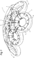
- Fig. 3 shows a perspective view of an embodiment of a dome 30 according to the present invention which is provided with cover elements 10.
- the cover elements 10 are configured as inflatable cushions which are connected to one another in such a way that the dome 30 is windproof and watertight.
- the cover elements 10 it will be clear that several embodiments of the cover elements 10 are possible in order to achieve this object. It is also conceivable for the cover elements 10 to be configured in such a way that they make it possible to use the dome 30, for example, as climbing structure. Furthermore, it is possible for the cover elements 10 to be adapted to generate energy, for example solar energy.
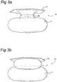
- Fig. 3a shows a perspective view of an embodiment of a cover element 10 which can be attached to a structural element 2 according to the present invention.
- the cover element 10 comprises an optionally fillable first cover part 11 which is connected to an optionally fillable second cover part 12 via an optionally fillable connecting part 26.
- the first cover part 11 is configured such that, in a position of use, it covers the axial opening 27 in the torus face of at least a single structural element 2 in a windproof and watertight manner.
- the optionally fillable connecting part 26 is accommodated in a fitting manner in the axial opening 27 in the torus face of a structural element 2.
- Other embodiments of the cover element 10 are conceivable.
- a cover element 10 may, for example, comprise a connecting part 26 which is provided on both sides thereof with second cover parts 12.
- a cover element 10 may, for example, also comprise a connecting part 26 which is provided on both side thereof with first cover parts 11.
- a cover element 10 may, for example, also comprise only one first cover part 11 or only one second cover part 12. Such a cover element 10 can be connected to a structural element 2 via a connecting element 7.
- Fig. 3b shows a perspective view of an assembly of the cover element 10 according to Fig. 3a and a structural element 2 according to the present invention in a position of use.
- the cover element 10 is connected to the structural element 2 due to the fact that the second cover part 12 and the first cover part 11 are situated in supporting contact on either side of the torus face of the structural element 2.
- the cover element 10 may also be configured in other ways in order to achieve a windproof and watertight sealing of at least a single structural element 2. It is, for example, possible to configure the cover elements 10 in such a manner that they overlap one another in use in the manner of roof tiles.
- Fig. 4 shows a perspective view of an embodiment of a tunnel-shaped structure 40 according to the present invention.
- the highest face of a tunnel-shaped structure 40 is preferably formed by structural elements 2 which are arranged in a hexagonal configuration. It will be clear that the tunnel-shaped structure 40 can be made windproof and watertight by connecting cover elements 10 and the structural elements 2, for example in a manner as has already been described above.
Claims (16)
- Verfahren zum Herstellen einer schalenförmigen Struktur (1), umfassend:Bereitstellen einer Vielzahl von torusförmigen Strukturelementen (2), die mit einem Füllmedium gefüllt werden können, und die jeweils um eine Torusachse verlaufen und jeweils eine Torusfläche umfassen, die quer zu der Torusachse gerichtet ist,Platzieren der Strukturelemente (2) aneinander in einer solchen Weise, dass die jeweiligen Torusflächen von benachbarten Strukturelementen (2) im Wesentlichen in Reihe miteinander oder unter einem geringen Winkel (α) zueinander verlaufen,Verbinden der Strukturelemente (2), die aneinander platziert worden sind,Füllen der Strukturelemente (2) mit einem Füllmedium, um eine schalenförmige Struktur (1), beispielsweise eine Kuppel oder einen Tunnel (30, 40) zu bilden.
- Verfahren nach Anspruch 1, umfassend ein Füllen der Strukturelemente (2) mit einem Gas, welches sich bei einem Überdruck bezogen auf atmosphärischem Druck befindet.
- Verfahren nach Anspruch 1, umfassend ein Füllen der Strukturelemente (2) mit einem härtbaren Füllmedium.
- Verfahren nach Anspruch 1, umfassend ein Füllen der Strukturelemente (2) mit einer Flüssigkeit.
- Verfahren nach einem der vorhergehenden Ansprüche, umfassend bei Betrachtung zumindest in einem Querschnitt der Struktur ein Platzieren von Torusflächen sämtlicher Strukturelemente (2), die sich in dem Querschnitt in einer solchen Weise befinden, dass die Struktur zumindest in dem Querschnitt einen monoton gekrümmten Abschnitt umfasst und vorzugsweise vollständig monoton gekrümmt ist.
- Verfahren nach einem der vorhergehenden Ansprüche, umfassend:Herstellen eines ersten Satzes von Strukturelementen (2), die aneinander angebracht sind und zusammen eine erste Reihe bilden,Füllen der Strukturelemente (2) dieser ersten Reihe in einer solchen Weise, dass ein Strukturabschnitt erhalten wird,nach dem Füllen der Strukturelemente (2) erfolgendes Anbringen von weiteren Strukturelementen (2) daran, die sich außerhalb der gefüllten Reihe befinden, Füllen der übrigen Strukturelemente (2).
- Verfahren nach einem der vorhergehenden Ansprüche, umfassend:Anbringen der Strukturelemente (2) aneinander mittels Kopplungselementen (6), die in jedem Falle in zwei benachbarte Strukturelemente (2) auf jeder Seite ihrer jeweiligen Torusflächen eingreifen,Füllen der Strukturelemente mit einem Füllmedium,Anwenden einer Zugspannung auf die Kopplungselemente (6) und Spannelemente (4) durch Füllen der Strukturelemente.
- Strukturelement (2) für die Verwendung bei dem Verfahren zum Herstellen einer schalenförmigen Struktur nach einem der vorhergehenden Ansprüche,
wobei das Strukturelement (2) eine flexible torusförmige Schale umfasst, die eine Torusachse und eine Torusfläche aufweist, welche quer zu der Torusachse gerichtet ist, wobei die Torusfläche eine erste Seite (91) und eine zweite Seite (92) aufweist, welche bei Betrachtung in einer Richtung längs der Torusachse auf gegenüberliegenden Seiten der Torusfläche liegen,
wobei die flexible torusförmige Schale ferner eine Innenkammer (20) und einen dichtbaren Einlass (9) in die Innenkammer (20) enthält, der gestaltet ist, um die Innenkammer (20) mit einem Füllmedium zu füllen,
wobei das Strukturelement (2) dadurch gekennzeichnet ist,
dass es ferner eine zweite Schicht (3), die eine Außenseite der flexiblen torusförmigen Schale bildet, Spannelemente (4), Befestigungselemente (5), Kopplungselemente (6) und Positionierungselemente (8) umfasst, die auf der zweiten Schicht (3) der flexiblen torusförmigen Schale an der ersten Seite (91) der Torusfläche und an der zweiten Seite (92) der Torusfläche angeordnet sind,
wobei die Befestigungselemente (5) ausgelegt sind, um die Spannelemente (4), die in einer radialen Richtung bezogen auf die Torusachse gerichtet sind, mittels der Positionierungselemente (8) in Position zu halten und die Spannelemente (4) in einer solchen Weise zu führen, dass sie mit den Kopplungselementen (6) verbindbar sind, um Strukturelemente (2) miteinander zu verbinden. - Strukturelement (2) nach Anspruch 8,
wobei die flexible torusförmige Schale eine im Wesentlichen undurchlässige Wand (21) und einen Schlauch (23) umfasst, der sich außerhalb der im Wesentlichen undurchlässigen Wand befindet,
wobei die im Wesentlichen undurchlässige Wand (21) mit einem dichtbaren Einlass (9) in die Innenkammer (20) versehen ist
und wobei der Schlauch (23) die Befestigungselemente (5) aufweist. - Strukturelement (2) nach Anspruch 9,
wobei die im Wesentlichen undurchlässige Wand (21) eine erste Seite und eine zweite Seite aufweist,
wobei die erste Seite der Innenkammer (20) zugewandt ist,
wobei die zweite Seite, während der Einlass (9) in die Innenkammer (20) freigelassen ist, mit einer ersten Schicht (22) bedeckt ist, die ein flexibles Material umfasst,
wobei die erste Schicht (22), während der Einlass (9) in die Innenkammer (20) freigelassen ist, mit der zweiten Schicht (3) bedeckt ist, die ein flexibles Material umfasst,
wobei, während der Einlass (9) in die Innenkammer (20) freigelassen ist,
wobei der Schlauch (23) zwischen der ersten Schicht (22) und der zweiten Schicht (3) angeordnet ist, während der Einlass (9) in die Innenkammer (20) freigelassen ist, wobei der Schlauch (23) ein flexibles Material umfasst und ausgelegt ist, um im Wesentlichen Membranspannungen in einer solchen Weise zu absorbieren, dass die Schale im Wesentlichen dimensionsbeständig ist, während das Füllmedium sich innerhalb letzterer bei einem Überdruck bezogen auf atmosphärischem Druck befindet. - Strukturelement (2) nach einem der Ansprüche 8 bis 10, wobei die Befestigungselemente (5) ausgelegt sind, um ein Abdeckelement (10) mit dem Strukturelement (2) zu verbinden.
- Strukturelement (2) nach einem der Ansprüche 8 bis 11, wobei auf der Außenseite der torusförmigen Schale ein Schutzelement (25) an der Stelle des äußeren Durchmessers der betreffenden Schale angeordnet ist und wobei das Schutzelement (25) in der Umfangsrichtung der Schale verläuft.
- Schalenförmige Struktur, hergestellt mittels des Verfahrens zum Herstellen einer schalenförmigen Struktur nach einem der Ansprüche 1 bis 7 unter Verwendung von Strukturelementen (2) nach einem der Ansprüche 8 bis 12,
wobei die einander zugewandten Teile der flexiblen torusförmigen Schalen von in jedem Fall zwei benachbarten Strukturelementen (2) aneinander anliegen und die Kopplungselemente (6) und Spannelemente (4) auf jeder Seite der jeweiligen Torusflächen der Strukturelemente (2) sich unter Zugvorspannung befinden. - Schalenförmige Struktur nach Anspruch 13, wobei ein Winkel (α) zwischen den Torusflächen benachbarter Strukturelemente (2) durch geeignete Wahl der Länge der Kopplungselemente (6) einstellbar ist.
- Schalenförmige Struktur nach Anspruch 13, wobei ein Winkel (α) zwischen den Torusflächen benachbarter Strukturelemente (2) durch geeignete Wahl der Länge der Spannelemente (4) einstellbar ist.
- Schalenförmige Struktur nach einem der Ansprüche 13 bis 15, wobei mit den Strukturelementen (2) Abdeckelemente (10) verbunden sind und wobei die Abdeckelemente (10) in einer solchen Weise ausgelegt sind, dass die Struktur windundurchlässig und wasserdicht ist.
Applications Claiming Priority (2)
| Application Number | Priority Date | Filing Date | Title |
|---|---|---|---|
| NL2006545A NL2006545C2 (nl) | 2011-04-05 | 2011-04-05 | Werkwijze voor het vervaardigen van een schaalvormige constructie, een constructie-element en een constructie. |
| PCT/NL2012/050175 WO2012138215A1 (en) | 2011-04-05 | 2012-03-21 | Method of producing a bowl - shaped structure, a structural element and a structure |
Publications (2)
| Publication Number | Publication Date |
|---|---|
| EP2694748A1 EP2694748A1 (de) | 2014-02-12 |
| EP2694748B1 true EP2694748B1 (de) | 2017-02-15 |
Family
ID=45930943
Family Applications (1)
| Application Number | Title | Priority Date | Filing Date |
|---|---|---|---|
| EP12712387.5A Not-in-force EP2694748B1 (de) | 2011-04-05 | 2012-03-21 | Verfahren zur herstellung einer schalenförmigen struktur, strukturelement und struktur |
Country Status (3)
| Country | Link |
|---|---|
| EP (1) | EP2694748B1 (de) |
| NL (1) | NL2006545C2 (de) |
| WO (1) | WO2012138215A1 (de) |
Families Citing this family (2)
| Publication number | Priority date | Publication date | Assignee | Title |
|---|---|---|---|---|
| FR2992286B1 (fr) * | 2012-06-20 | 2014-07-18 | Eads Europ Aeronautic Defence | Ballon stratospherique a tenue a la compression amelioree |
| FR3045082B1 (fr) * | 2015-12-15 | 2019-07-26 | Daniel Billecard | Systeme pour reduire les frais de chauffage et/ou de refroidissement d'un local |
Citations (3)
| Publication number | Priority date | Publication date | Assignee | Title |
|---|---|---|---|---|
| US3508270A (en) * | 1967-01-04 | 1970-04-21 | Bell Telephone Labor Inc | Inflatable communications antenna satellite |
| US5201345A (en) * | 1991-07-23 | 1993-04-13 | The United States Of America As Represented By The United States Department Of Energy | Inflatable containment diaphragm for sealing and removing stacks |
| US7380802B1 (en) * | 2003-05-19 | 2008-06-03 | Duke Technologies, Inc. | Sliding recreational device |
Family Cites Families (5)
| Publication number | Priority date | Publication date | Assignee | Title |
|---|---|---|---|---|
| DE2324214A1 (de) * | 1973-05-12 | 1974-11-21 | Continental Gummi Werke Ag | Ufer- oder kuestenschutzeinrichtung aus kraftfahrzeugreifen |
| US4583330A (en) | 1978-08-28 | 1986-04-22 | Huang Yen T | Modular inflatable dome structure |
| WO2000058575A1 (en) * | 1999-03-26 | 2000-10-05 | Provitola Anthony I | Structural system of torsion/toroidal elements and methods of construction therewith |
| AT501180B1 (de) * | 2004-11-16 | 2006-10-15 | Thomas Mag Herzig | Zellenförmiges, aufblasbares bauelement |
| US20080276545A1 (en) * | 2006-04-07 | 2008-11-13 | Publicover Mark W | Construction system with inflated members |
-
2011
- 2011-04-05 NL NL2006545A patent/NL2006545C2/nl not_active IP Right Cessation
-
2012
- 2012-03-21 WO PCT/NL2012/050175 patent/WO2012138215A1/en active Application Filing
- 2012-03-21 EP EP12712387.5A patent/EP2694748B1/de not_active Not-in-force
Patent Citations (3)
| Publication number | Priority date | Publication date | Assignee | Title |
|---|---|---|---|---|
| US3508270A (en) * | 1967-01-04 | 1970-04-21 | Bell Telephone Labor Inc | Inflatable communications antenna satellite |
| US5201345A (en) * | 1991-07-23 | 1993-04-13 | The United States Of America As Represented By The United States Department Of Energy | Inflatable containment diaphragm for sealing and removing stacks |
| US7380802B1 (en) * | 2003-05-19 | 2008-06-03 | Duke Technologies, Inc. | Sliding recreational device |
Also Published As
| Publication number | Publication date |
|---|---|
| EP2694748A1 (de) | 2014-02-12 |
| NL2006545C2 (nl) | 2012-10-08 |
| WO2012138215A1 (en) | 2012-10-11 |
Similar Documents
| Publication | Publication Date | Title |
|---|---|---|
| EP2773819B1 (de) | Konstruktionseinheit für sofortigen oder permanenten schutz | |
| US20130014467A1 (en) | Reconstruction methods for structural elements | |
| US8683954B2 (en) | Finfish containment pens and polyhedral structures | |
| CA2989402C (en) | Rapid deployment flood barrier | |
| US6672800B2 (en) | Portable flood control revetment | |
| US20220250722A1 (en) | Wind Turbine Comprising a Floating Foundation having a Plurality of Buoyancy Bodies | |
| US9498065B2 (en) | Modular structure and method for preparing same | |
| EP2694748B1 (de) | Verfahren zur herstellung einer schalenförmigen struktur, strukturelement und struktur | |
| US20100101164A1 (en) | Structural element for a protective wall | |
| US6925762B2 (en) | Arch structure | |
| EP0639497B1 (de) | Ankergerät für eine schwimmkonstruktion, und schwimmkonstruktion | |
| RU2711806C1 (ru) | Блок ограждения загона для содержания сельскохозяйственных животных | |
| US20160060836A1 (en) | Inflatable flood defense structural unit and arrangement | |
| CA2299823A1 (en) | Portable flood barrier | |
| JPH04111873A (ja) | ドーム型屋根及びその構築法 | |
| CZ11848U1 (cs) | Díl vysokotlaké bariéry a vysokotlaká bariéra | |
| AU2006225165A1 (en) | Foundation Void Tanks |
Legal Events
| Date | Code | Title | Description |
|---|---|---|---|
| PUAI | Public reference made under article 153(3) epc to a published international application that has entered the european phase |
Free format text: ORIGINAL CODE: 0009012 |
|
| 17P | Request for examination filed |
Effective date: 20131002 |
|
| AK | Designated contracting states |
Kind code of ref document: A1 Designated state(s): AL AT BE BG CH CY CZ DE DK EE ES FI FR GB GR HR HU IE IS IT LI LT LU LV MC MK MT NL NO PL PT RO RS SE SI SK SM TR |
|
| DAX | Request for extension of the european patent (deleted) | ||
| 17Q | First examination report despatched |
Effective date: 20140716 |
|
| RIN1 | Information on inventor provided before grant (corrected) |
Inventor name: RUTTEN, CONSTANTIJN, MARTHA, JOZEF |
|
| GRAP | Despatch of communication of intention to grant a patent |
Free format text: ORIGINAL CODE: EPIDOSNIGR1 |
|
| INTG | Intention to grant announced |
Effective date: 20160907 |
|
| GRAJ | Information related to disapproval of communication of intention to grant by the applicant or resumption of examination proceedings by the epo deleted |
Free format text: ORIGINAL CODE: EPIDOSDIGR1 |
|
| GRAR | Information related to intention to grant a patent recorded |
Free format text: ORIGINAL CODE: EPIDOSNIGR71 |
|
| GRAS | Grant fee paid |
Free format text: ORIGINAL CODE: EPIDOSNIGR3 |
|
| GRAA | (expected) grant |
Free format text: ORIGINAL CODE: 0009210 |
|
| INTC | Intention to grant announced (deleted) | ||
| INTG | Intention to grant announced |
Effective date: 20170105 |
|
| AK | Designated contracting states |
Kind code of ref document: B1 Designated state(s): AL AT BE BG CH CY CZ DE DK EE ES FI FR GB GR HR HU IE IS IT LI LT LU LV MC MK MT NL NO PL PT RO RS SE SI SK SM TR |
|
| REG | Reference to a national code |
Ref country code: CH Ref legal event code: EP Ref country code: GB Ref legal event code: FG4D |
|
| REG | Reference to a national code |
Ref country code: IE Ref legal event code: FG4D |
|
| REG | Reference to a national code |
Ref country code: AT Ref legal event code: REF Ref document number: 867984 Country of ref document: AT Kind code of ref document: T Effective date: 20170315 |
|
| REG | Reference to a national code |
Ref country code: FR Ref legal event code: PLFP Year of fee payment: 6 |
|
| REG | Reference to a national code |
Ref country code: DE Ref legal event code: R096 Ref document number: 602012028694 Country of ref document: DE |
|
| REG | Reference to a national code |
Ref country code: CH Ref legal event code: NV Representative=s name: FIAMMENGHI-FIAMMENGHI, CH |
|
| REG | Reference to a national code |
Ref country code: NL Ref legal event code: FP |
|
| REG | Reference to a national code |
Ref country code: LT Ref legal event code: MG4D |
|
| REG | Reference to a national code |
Ref country code: AT Ref legal event code: MK05 Ref document number: 867984 Country of ref document: AT Kind code of ref document: T Effective date: 20170215 |
|
| PG25 | Lapsed in a contracting state [announced via postgrant information from national office to epo] |
Ref country code: GR Free format text: LAPSE BECAUSE OF FAILURE TO SUBMIT A TRANSLATION OF THE DESCRIPTION OR TO PAY THE FEE WITHIN THE PRESCRIBED TIME-LIMIT Effective date: 20170516 Ref country code: FI Free format text: LAPSE BECAUSE OF FAILURE TO SUBMIT A TRANSLATION OF THE DESCRIPTION OR TO PAY THE FEE WITHIN THE PRESCRIBED TIME-LIMIT Effective date: 20170215 Ref country code: NO Free format text: LAPSE BECAUSE OF FAILURE TO SUBMIT A TRANSLATION OF THE DESCRIPTION OR TO PAY THE FEE WITHIN THE PRESCRIBED TIME-LIMIT Effective date: 20170515 Ref country code: LT Free format text: LAPSE BECAUSE OF FAILURE TO SUBMIT A TRANSLATION OF THE DESCRIPTION OR TO PAY THE FEE WITHIN THE PRESCRIBED TIME-LIMIT Effective date: 20170215 Ref country code: HR Free format text: LAPSE BECAUSE OF FAILURE TO SUBMIT A TRANSLATION OF THE DESCRIPTION OR TO PAY THE FEE WITHIN THE PRESCRIBED TIME-LIMIT Effective date: 20170215 |
|
| PG25 | Lapsed in a contracting state [announced via postgrant information from national office to epo] |
Ref country code: LV Free format text: LAPSE BECAUSE OF FAILURE TO SUBMIT A TRANSLATION OF THE DESCRIPTION OR TO PAY THE FEE WITHIN THE PRESCRIBED TIME-LIMIT Effective date: 20170215 Ref country code: ES Free format text: LAPSE BECAUSE OF FAILURE TO SUBMIT A TRANSLATION OF THE DESCRIPTION OR TO PAY THE FEE WITHIN THE PRESCRIBED TIME-LIMIT Effective date: 20170215 Ref country code: PT Free format text: LAPSE BECAUSE OF FAILURE TO SUBMIT A TRANSLATION OF THE DESCRIPTION OR TO PAY THE FEE WITHIN THE PRESCRIBED TIME-LIMIT Effective date: 20170615 Ref country code: BG Free format text: LAPSE BECAUSE OF FAILURE TO SUBMIT A TRANSLATION OF THE DESCRIPTION OR TO PAY THE FEE WITHIN THE PRESCRIBED TIME-LIMIT Effective date: 20170515 Ref country code: RS Free format text: LAPSE BECAUSE OF FAILURE TO SUBMIT A TRANSLATION OF THE DESCRIPTION OR TO PAY THE FEE WITHIN THE PRESCRIBED TIME-LIMIT Effective date: 20170215 Ref country code: AT Free format text: LAPSE BECAUSE OF FAILURE TO SUBMIT A TRANSLATION OF THE DESCRIPTION OR TO PAY THE FEE WITHIN THE PRESCRIBED TIME-LIMIT Effective date: 20170215 Ref country code: SE Free format text: LAPSE BECAUSE OF FAILURE TO SUBMIT A TRANSLATION OF THE DESCRIPTION OR TO PAY THE FEE WITHIN THE PRESCRIBED TIME-LIMIT Effective date: 20170215 |
|
| PG25 | Lapsed in a contracting state [announced via postgrant information from national office to epo] |
Ref country code: SK Free format text: LAPSE BECAUSE OF FAILURE TO SUBMIT A TRANSLATION OF THE DESCRIPTION OR TO PAY THE FEE WITHIN THE PRESCRIBED TIME-LIMIT Effective date: 20170215 Ref country code: CZ Free format text: LAPSE BECAUSE OF FAILURE TO SUBMIT A TRANSLATION OF THE DESCRIPTION OR TO PAY THE FEE WITHIN THE PRESCRIBED TIME-LIMIT Effective date: 20170215 Ref country code: IT Free format text: LAPSE BECAUSE OF FAILURE TO SUBMIT A TRANSLATION OF THE DESCRIPTION OR TO PAY THE FEE WITHIN THE PRESCRIBED TIME-LIMIT Effective date: 20170215 Ref country code: EE Free format text: LAPSE BECAUSE OF FAILURE TO SUBMIT A TRANSLATION OF THE DESCRIPTION OR TO PAY THE FEE WITHIN THE PRESCRIBED TIME-LIMIT Effective date: 20170215 Ref country code: RO Free format text: LAPSE BECAUSE OF FAILURE TO SUBMIT A TRANSLATION OF THE DESCRIPTION OR TO PAY THE FEE WITHIN THE PRESCRIBED TIME-LIMIT Effective date: 20170215 |
|
| REG | Reference to a national code |
Ref country code: DE Ref legal event code: R097 Ref document number: 602012028694 Country of ref document: DE |
|
| PG25 | Lapsed in a contracting state [announced via postgrant information from national office to epo] |
Ref country code: SM Free format text: LAPSE BECAUSE OF FAILURE TO SUBMIT A TRANSLATION OF THE DESCRIPTION OR TO PAY THE FEE WITHIN THE PRESCRIBED TIME-LIMIT Effective date: 20170215 Ref country code: DK Free format text: LAPSE BECAUSE OF FAILURE TO SUBMIT A TRANSLATION OF THE DESCRIPTION OR TO PAY THE FEE WITHIN THE PRESCRIBED TIME-LIMIT Effective date: 20170215 Ref country code: PL Free format text: LAPSE BECAUSE OF FAILURE TO SUBMIT A TRANSLATION OF THE DESCRIPTION OR TO PAY THE FEE WITHIN THE PRESCRIBED TIME-LIMIT Effective date: 20170215 Ref country code: MC Free format text: LAPSE BECAUSE OF FAILURE TO SUBMIT A TRANSLATION OF THE DESCRIPTION OR TO PAY THE FEE WITHIN THE PRESCRIBED TIME-LIMIT Effective date: 20170215 |
|
| PLBE | No opposition filed within time limit |
Free format text: ORIGINAL CODE: 0009261 |
|
| STAA | Information on the status of an ep patent application or granted ep patent |
Free format text: STATUS: NO OPPOSITION FILED WITHIN TIME LIMIT |
|
| RAP2 | Party data changed (patent owner data changed or rights of a patent transferred) |
Owner name: DAEDALISSIMO N.V. |
|
| REG | Reference to a national code |
Ref country code: IE Ref legal event code: MM4A |
|
| REG | Reference to a national code |
Ref country code: DE Ref legal event code: R081 Ref document number: 602012028694 Country of ref document: DE Owner name: DAEDALISSIMO N.V., NL Free format text: FORMER OWNER: DAEDALISSIMO N.V., EINDHOVEN, NL |
|
| 26N | No opposition filed |
Effective date: 20171116 |
|
| PG25 | Lapsed in a contracting state [announced via postgrant information from national office to epo] |
Ref country code: LU Free format text: LAPSE BECAUSE OF NON-PAYMENT OF DUE FEES Effective date: 20170321 |
|
| REG | Reference to a national code |
Ref country code: FR Ref legal event code: PLFP Year of fee payment: 7 |
|
| PG25 | Lapsed in a contracting state [announced via postgrant information from national office to epo] |
Ref country code: SI Free format text: LAPSE BECAUSE OF FAILURE TO SUBMIT A TRANSLATION OF THE DESCRIPTION OR TO PAY THE FEE WITHIN THE PRESCRIBED TIME-LIMIT Effective date: 20170215 Ref country code: IE Free format text: LAPSE BECAUSE OF NON-PAYMENT OF DUE FEES Effective date: 20170321 |
|
| REG | Reference to a national code |
Ref country code: CH Ref legal event code: PCOW Free format text: NEW ADDRESS: TURELUUR 82, 5804 VM VENRAY (NL) |
|
| REG | Reference to a national code |
Ref country code: BE Ref legal event code: MM Effective date: 20170331 |
|
| PG25 | Lapsed in a contracting state [announced via postgrant information from national office to epo] |
Ref country code: BE Free format text: LAPSE BECAUSE OF NON-PAYMENT OF DUE FEES Effective date: 20170331 |
|
| PG25 | Lapsed in a contracting state [announced via postgrant information from national office to epo] |
Ref country code: MT Free format text: LAPSE BECAUSE OF NON-PAYMENT OF DUE FEES Effective date: 20170321 |
|
| PG25 | Lapsed in a contracting state [announced via postgrant information from national office to epo] |
Ref country code: HU Free format text: LAPSE BECAUSE OF FAILURE TO SUBMIT A TRANSLATION OF THE DESCRIPTION OR TO PAY THE FEE WITHIN THE PRESCRIBED TIME-LIMIT; INVALID AB INITIO Effective date: 20120321 |
|
| PG25 | Lapsed in a contracting state [announced via postgrant information from national office to epo] |
Ref country code: CY Free format text: LAPSE BECAUSE OF NON-PAYMENT OF DUE FEES Effective date: 20170215 |
|
| PG25 | Lapsed in a contracting state [announced via postgrant information from national office to epo] |
Ref country code: MK Free format text: LAPSE BECAUSE OF FAILURE TO SUBMIT A TRANSLATION OF THE DESCRIPTION OR TO PAY THE FEE WITHIN THE PRESCRIBED TIME-LIMIT Effective date: 20170215 |
|
| PG25 | Lapsed in a contracting state [announced via postgrant information from national office to epo] |
Ref country code: TR Free format text: LAPSE BECAUSE OF FAILURE TO SUBMIT A TRANSLATION OF THE DESCRIPTION OR TO PAY THE FEE WITHIN THE PRESCRIBED TIME-LIMIT Effective date: 20170215 |
|
| PG25 | Lapsed in a contracting state [announced via postgrant information from national office to epo] |
Ref country code: AL Free format text: LAPSE BECAUSE OF FAILURE TO SUBMIT A TRANSLATION OF THE DESCRIPTION OR TO PAY THE FEE WITHIN THE PRESCRIBED TIME-LIMIT Effective date: 20170215 Ref country code: IS Free format text: LAPSE BECAUSE OF FAILURE TO SUBMIT A TRANSLATION OF THE DESCRIPTION OR TO PAY THE FEE WITHIN THE PRESCRIBED TIME-LIMIT Effective date: 20170615 |
|
| PGFP | Annual fee paid to national office [announced via postgrant information from national office to epo] |
Ref country code: FR Payment date: 20210324 Year of fee payment: 10 Ref country code: CH Payment date: 20210326 Year of fee payment: 10 |
|
| PGFP | Annual fee paid to national office [announced via postgrant information from national office to epo] |
Ref country code: DE Payment date: 20210324 Year of fee payment: 10 Ref country code: GB Payment date: 20210319 Year of fee payment: 10 |
|
| PGFP | Annual fee paid to national office [announced via postgrant information from national office to epo] |
Ref country code: NL Payment date: 20220315 Year of fee payment: 11 |
|
| REG | Reference to a national code |
Ref country code: DE Ref legal event code: R119 Ref document number: 602012028694 Country of ref document: DE |
|
| REG | Reference to a national code |
Ref country code: CH Ref legal event code: PL |
|
| GBPC | Gb: european patent ceased through non-payment of renewal fee |
Effective date: 20220321 |
|
| PG25 | Lapsed in a contracting state [announced via postgrant information from national office to epo] |
Ref country code: LI Free format text: LAPSE BECAUSE OF NON-PAYMENT OF DUE FEES Effective date: 20220331 Ref country code: GB Free format text: LAPSE BECAUSE OF NON-PAYMENT OF DUE FEES Effective date: 20220321 Ref country code: FR Free format text: LAPSE BECAUSE OF NON-PAYMENT OF DUE FEES Effective date: 20220331 Ref country code: DE Free format text: LAPSE BECAUSE OF NON-PAYMENT OF DUE FEES Effective date: 20221001 Ref country code: CH Free format text: LAPSE BECAUSE OF NON-PAYMENT OF DUE FEES Effective date: 20220331 |
|
| REG | Reference to a national code |
Ref country code: NL Ref legal event code: MM Effective date: 20230401 |
|
| PG25 | Lapsed in a contracting state [announced via postgrant information from national office to epo] |
Ref country code: NL Free format text: LAPSE BECAUSE OF NON-PAYMENT OF DUE FEES Effective date: 20230401 |