EP2694154B1 - Implantierbare leitung - Google Patents
Implantierbare leitung Download PDFInfo
- Publication number
- EP2694154B1 EP2694154B1 EP12767575.9A EP12767575A EP2694154B1 EP 2694154 B1 EP2694154 B1 EP 2694154B1 EP 12767575 A EP12767575 A EP 12767575A EP 2694154 B1 EP2694154 B1 EP 2694154B1
- Authority
- EP
- European Patent Office
- Prior art keywords
- lead
- antenna
- electrodes
- wireless
- enclosure
- Prior art date
- Legal status (The legal status is an assumption and is not a legal conclusion. Google has not performed a legal analysis and makes no representation as to the accuracy of the status listed.)
- Active
Links
- 210000001519 tissue Anatomy 0.000 claims description 53
- 238000010168 coupling process Methods 0.000 claims description 50
- 238000005859 coupling reaction Methods 0.000 claims description 50
- 230000008878 coupling Effects 0.000 claims description 49
- 230000001537 neural effect Effects 0.000 claims description 28
- 230000000638 stimulation Effects 0.000 claims description 25
- 230000003750 conditioning effect Effects 0.000 claims description 20
- -1 polydimethylsiloxane Polymers 0.000 claims description 10
- BASFCYQUMIYNBI-UHFFFAOYSA-N platinum Chemical compound [Pt] BASFCYQUMIYNBI-UHFFFAOYSA-N 0.000 claims description 8
- 230000001939 inductive effect Effects 0.000 claims description 7
- 239000004205 dimethyl polysiloxane Substances 0.000 claims description 6
- 229920000435 poly(dimethylsiloxane) Polymers 0.000 claims description 6
- 229920001343 polytetrafluoroethylene Polymers 0.000 claims description 6
- 239000004810 polytetrafluoroethylene Substances 0.000 claims description 6
- 239000011248 coating agent Substances 0.000 claims description 5
- 238000000576 coating method Methods 0.000 claims description 5
- 210000000944 nerve tissue Anatomy 0.000 claims description 5
- 229920000642 polymer Polymers 0.000 claims description 5
- 229910002601 GaN Inorganic materials 0.000 claims description 4
- JMASRVWKEDWRBT-UHFFFAOYSA-N Gallium nitride Chemical compound [Ga]#N JMASRVWKEDWRBT-UHFFFAOYSA-N 0.000 claims description 4
- NRTOMJZYCJJWKI-UHFFFAOYSA-N Titanium nitride Chemical compound [Ti]#N NRTOMJZYCJJWKI-UHFFFAOYSA-N 0.000 claims description 4
- HTXDPTMKBJXEOW-UHFFFAOYSA-N dioxoiridium Chemical compound O=[Ir]=O HTXDPTMKBJXEOW-UHFFFAOYSA-N 0.000 claims description 4
- 229910000457 iridium oxide Inorganic materials 0.000 claims description 4
- 229910052697 platinum Inorganic materials 0.000 claims description 4
- HWLDNSXPUQTBOD-UHFFFAOYSA-N platinum-iridium alloy Chemical compound [Ir].[Pt] HWLDNSXPUQTBOD-UHFFFAOYSA-N 0.000 claims description 4
- 230000007797 corrosion Effects 0.000 claims description 3
- 238000005260 corrosion Methods 0.000 claims description 3
- 230000005284 excitation Effects 0.000 claims description 3
- 229920000052 poly(p-xylylene) Polymers 0.000 claims description 3
- 239000004417 polycarbonate Substances 0.000 claims description 3
- 229920000515 polycarbonate Polymers 0.000 claims description 3
- 229920002379 silicone rubber Polymers 0.000 claims description 3
- 239000003990 capacitor Substances 0.000 claims description 2
- 238000002955 isolation Methods 0.000 claims description 2
- 238000004377 microelectronic Methods 0.000 claims description 2
- WABPQHHGFIMREM-NOHWODKXSA-N lead-200 Chemical compound [200Pb] WABPQHHGFIMREM-NOHWODKXSA-N 0.000 description 27
- 238000001125 extrusion Methods 0.000 description 18
- 241001269524 Dura Species 0.000 description 17
- 210000000278 spinal cord Anatomy 0.000 description 17
- 210000005036 nerve Anatomy 0.000 description 11
- 238000000034 method Methods 0.000 description 10
- 238000002513 implantation Methods 0.000 description 6
- 238000003780 insertion Methods 0.000 description 5
- 230000037431 insertion Effects 0.000 description 5
- 239000000463 material Substances 0.000 description 5
- 208000002193 Pain Diseases 0.000 description 4
- 230000008901 benefit Effects 0.000 description 4
- 239000000835 fiber Substances 0.000 description 4
- 239000010410 layer Substances 0.000 description 4
- WABPQHHGFIMREM-IGMARMGPSA-N lead-207 Chemical compound [207Pb] WABPQHHGFIMREM-IGMARMGPSA-N 0.000 description 4
- 229910052751 metal Inorganic materials 0.000 description 4
- 239000002184 metal Substances 0.000 description 4
- 231100000241 scar Toxicity 0.000 description 4
- 238000002560 therapeutic procedure Methods 0.000 description 4
- 210000003284 horn Anatomy 0.000 description 3
- 239000007943 implant Substances 0.000 description 3
- 230000007246 mechanism Effects 0.000 description 3
- 230000005012 migration Effects 0.000 description 3
- 238000013508 migration Methods 0.000 description 3
- 210000000578 peripheral nerve Anatomy 0.000 description 3
- 210000003594 spinal ganglia Anatomy 0.000 description 3
- 210000000273 spinal nerve root Anatomy 0.000 description 3
- 238000012546 transfer Methods 0.000 description 3
- 210000005166 vasculature Anatomy 0.000 description 3
- 206010002383 Angina Pectoris Diseases 0.000 description 2
- 238000004873 anchoring Methods 0.000 description 2
- 210000000988 bone and bone Anatomy 0.000 description 2
- 238000006243 chemical reaction Methods 0.000 description 2
- 230000001684 chronic effect Effects 0.000 description 2
- 210000001951 dura mater Anatomy 0.000 description 2
- 230000008030 elimination Effects 0.000 description 2
- 238000003379 elimination reaction Methods 0.000 description 2
- 239000004033 plastic Substances 0.000 description 2
- 229920003023 plastic Polymers 0.000 description 2
- 230000008569 process Effects 0.000 description 2
- 230000004936 stimulating effect Effects 0.000 description 2
- 238000007920 subcutaneous administration Methods 0.000 description 2
- 230000001225 therapeutic effect Effects 0.000 description 2
- 208000008035 Back Pain Diseases 0.000 description 1
- 208000018522 Gastrointestinal disease Diseases 0.000 description 1
- 208000008930 Low Back Pain Diseases 0.000 description 1
- 208000018262 Peripheral vascular disease Diseases 0.000 description 1
- 206010037779 Radiculopathy Diseases 0.000 description 1
- 206010054880 Vascular insufficiency Diseases 0.000 description 1
- 230000003187 abdominal effect Effects 0.000 description 1
- 238000002679 ablation Methods 0.000 description 1
- 238000013459 approach Methods 0.000 description 1
- 210000000576 arachnoid Anatomy 0.000 description 1
- 230000002238 attenuated effect Effects 0.000 description 1
- 239000000560 biocompatible material Substances 0.000 description 1
- 229920000249 biocompatible polymer Polymers 0.000 description 1
- 230000005540 biological transmission Effects 0.000 description 1
- 210000004556 brain Anatomy 0.000 description 1
- 210000000133 brain stem Anatomy 0.000 description 1
- 230000015556 catabolic process Effects 0.000 description 1
- 210000003710 cerebral cortex Anatomy 0.000 description 1
- 239000011247 coating layer Substances 0.000 description 1
- 150000001875 compounds Chemical class 0.000 description 1
- 210000003792 cranial nerve Anatomy 0.000 description 1
- 238000006731 degradation reaction Methods 0.000 description 1
- 230000001419 dependent effect Effects 0.000 description 1
- 238000011161 development Methods 0.000 description 1
- 239000003989 dielectric material Substances 0.000 description 1
- 238000009826 distribution Methods 0.000 description 1
- 238000005516 engineering process Methods 0.000 description 1
- 208000015181 infectious disease Diseases 0.000 description 1
- 208000014674 injury Diseases 0.000 description 1
- 238000007913 intrathecal administration Methods 0.000 description 1
- 230000007794 irritation Effects 0.000 description 1
- WABPQHHGFIMREM-UHFFFAOYSA-N lead(0) Chemical compound [Pb] WABPQHHGFIMREM-UHFFFAOYSA-N 0.000 description 1
- 210000003041 ligament Anatomy 0.000 description 1
- 230000007774 longterm Effects 0.000 description 1
- 210000004705 lumbosacral region Anatomy 0.000 description 1
- 238000004519 manufacturing process Methods 0.000 description 1
- 239000012528 membrane Substances 0.000 description 1
- 150000002739 metals Chemical class 0.000 description 1
- 238000012986 modification Methods 0.000 description 1
- 230000004048 modification Effects 0.000 description 1
- 208000004296 neuralgia Diseases 0.000 description 1
- 230000000926 neurological effect Effects 0.000 description 1
- 230000002981 neuropathic effect Effects 0.000 description 1
- 208000021722 neuropathic pain Diseases 0.000 description 1
- 230000009972 noncorrosive effect Effects 0.000 description 1
- 230000035699 permeability Effects 0.000 description 1
- 229920002635 polyurethane Polymers 0.000 description 1
- 239000004814 polyurethane Substances 0.000 description 1
- 230000009467 reduction Effects 0.000 description 1
- 230000037390 scarring Effects 0.000 description 1
- 230000001953 sensory effect Effects 0.000 description 1
- 125000006850 spacer group Chemical group 0.000 description 1
- 210000003009 spinothalamic tract Anatomy 0.000 description 1
- 230000008685 targeting Effects 0.000 description 1
- 238000012360 testing method Methods 0.000 description 1
- 210000000115 thoracic cavity Anatomy 0.000 description 1
- 230000009772 tissue formation Effects 0.000 description 1
- 230000008733 trauma Effects 0.000 description 1
- 210000000427 trigeminal ganglion Anatomy 0.000 description 1
- 208000023577 vascular insufficiency disease Diseases 0.000 description 1
Images


Classifications
-
- A—HUMAN NECESSITIES
- A61—MEDICAL OR VETERINARY SCIENCE; HYGIENE
- A61N—ELECTROTHERAPY; MAGNETOTHERAPY; RADIATION THERAPY; ULTRASOUND THERAPY
- A61N1/00—Electrotherapy; Circuits therefor
- A61N1/18—Applying electric currents by contact electrodes
- A61N1/32—Applying electric currents by contact electrodes alternating or intermittent currents
- A61N1/36—Applying electric currents by contact electrodes alternating or intermittent currents for stimulation
- A61N1/3605—Implantable neurostimulators for stimulating central or peripheral nerve system
- A61N1/3606—Implantable neurostimulators for stimulating central or peripheral nerve system adapted for a particular treatment
- A61N1/36071—Pain
-
- A—HUMAN NECESSITIES
- A61—MEDICAL OR VETERINARY SCIENCE; HYGIENE
- A61N—ELECTROTHERAPY; MAGNETOTHERAPY; RADIATION THERAPY; ULTRASOUND THERAPY
- A61N1/00—Electrotherapy; Circuits therefor
- A61N1/02—Details
- A61N1/04—Electrodes
- A61N1/05—Electrodes for implantation or insertion into the body, e.g. heart electrode
- A61N1/0551—Spinal or peripheral nerve electrodes
-
- A—HUMAN NECESSITIES
- A61—MEDICAL OR VETERINARY SCIENCE; HYGIENE
- A61N—ELECTROTHERAPY; MAGNETOTHERAPY; RADIATION THERAPY; ULTRASOUND THERAPY
- A61N1/00—Electrotherapy; Circuits therefor
- A61N1/18—Applying electric currents by contact electrodes
- A61N1/32—Applying electric currents by contact electrodes alternating or intermittent currents
- A61N1/36—Applying electric currents by contact electrodes alternating or intermittent currents for stimulation
- A61N1/372—Arrangements in connection with the implantation of stimulators
- A61N1/37211—Means for communicating with stimulators
- A61N1/37217—Means for communicating with stimulators characterised by the communication link, e.g. acoustic or tactile
- A61N1/37223—Circuits for electromagnetic coupling
- A61N1/37229—Shape or location of the implanted or external antenna
-
- A—HUMAN NECESSITIES
- A61—MEDICAL OR VETERINARY SCIENCE; HYGIENE
- A61N—ELECTROTHERAPY; MAGNETOTHERAPY; RADIATION THERAPY; ULTRASOUND THERAPY
- A61N1/00—Electrotherapy; Circuits therefor
- A61N1/18—Applying electric currents by contact electrodes
- A61N1/32—Applying electric currents by contact electrodes alternating or intermittent currents
- A61N1/36—Applying electric currents by contact electrodes alternating or intermittent currents for stimulation
- A61N1/3605—Implantable neurostimulators for stimulating central or peripheral nerve system
- A61N1/36128—Control systems
- A61N1/36146—Control systems specified by the stimulation parameters
- A61N1/36182—Direction of the electrical field, e.g. with sleeve around stimulating electrode
-
- A—HUMAN NECESSITIES
- A61—MEDICAL OR VETERINARY SCIENCE; HYGIENE
- A61N—ELECTROTHERAPY; MAGNETOTHERAPY; RADIATION THERAPY; ULTRASOUND THERAPY
- A61N1/00—Electrotherapy; Circuits therefor
- A61N1/18—Applying electric currents by contact electrodes
- A61N1/32—Applying electric currents by contact electrodes alternating or intermittent currents
- A61N1/36—Applying electric currents by contact electrodes alternating or intermittent currents for stimulation
- A61N1/372—Arrangements in connection with the implantation of stimulators
- A61N1/37205—Microstimulators, e.g. implantable through a cannula
-
- A—HUMAN NECESSITIES
- A61—MEDICAL OR VETERINARY SCIENCE; HYGIENE
- A61N—ELECTROTHERAPY; MAGNETOTHERAPY; RADIATION THERAPY; ULTRASOUND THERAPY
- A61N1/00—Electrotherapy; Circuits therefor
- A61N1/18—Applying electric currents by contact electrodes
- A61N1/32—Applying electric currents by contact electrodes alternating or intermittent currents
- A61N1/36—Applying electric currents by contact electrodes alternating or intermittent currents for stimulation
- A61N1/372—Arrangements in connection with the implantation of stimulators
- A61N1/378—Electrical supply
- A61N1/3787—Electrical supply from an external energy source
Definitions
- This description is related to implantable neural stimulators.
- a variety of therapeutic intra-body electrical stimulation techniques can treat neuropathic conditions. These techniques may utilize a subcutaneous battery operated implantable pulse generator (IPG) connected to one or more implantable wired leads. These leads have numerous failure modes, including mechanical dislodgement, impingement of the lead - extension tubing, infection, and uncomfortable irritation from the IPG and extension tubing. Various types of spinal cord stimulation (SCS) leads have been used to provide therapeutic pain relief. These lead configurations often include cylindrical percutaneous leads and paddle lead form factors. Cylindrical percutaneous leads typically have diameters in the range of 1.3 mm and contain a number of circular electrodes used for effectiveness testing during a trial implant period, and in many cases for the permanent implantation. Paddle leads, however, contain electrodes with a greater surface area directionally targeted for control over the excitation of the nerve bundles and may require surgical laminotomy.
- WO 2010/104569 A1 describes a system and method for energy transfer between a transmitting unit and a receiving unit.
- the transmitting unit has a transmitting antenna circuit having a first resonant frequency and a high quality factor.
- WO 2007/059386 A2 describes an implantable medical device is configured so that all of the major components including a housing and attached leads are disposed within the vasculature of a patient.
- a tether extends from the housing of the device to an implant location where the tether is secured to tissue outside of the vasculature.
- an intravascular medical device may be implanted at a location remote from final placement, delivered via the vasculature and anchored at the initial entry point.
- US 2003/0078633 A1 describes the provision of electrical therapy by delivering electrical pulses through at least one (and in some embodiments two or more) subcutaneously implanted electrode to stimulate one or more target nerves in a selected volume of tissue.
- the described approach does not need to position the electrodes in direct contact with a specific nerve or the spinal column. Instead, the electrode can be implanted at an indeterminate distance from the target nerve.
- Other embodiments provide implantable neurostimulators with a pair of electrodes which can be connected to a common pulse system. Each electrodes may include two or more contacts spaced 3 cm or more from one another and the electrodes are implantable at distances of 5 cm or more apart.
- the common pulse system may also be implantable.
- US 2010/0269339 A1 describes a process for fabricating a medical lead.
- the wireless lead includes: an enclosure; the enclosure housing; a) one or more electrodes configured to apply one or more electrical pulses to a neural tissue; b) a first antenna configured to receive, from a second antenna through electrical radiative coupling, an input 25 signal containing electrical energy, the second antenna being physically separate from the implantable neural stimulator lead; c) one or more circuits electrically connected to the first antenna, the circuits configured to create the one or more electrical pulses suitable for stimulation of the neural tissue using the electrical energy contained in the input signal, and supply the one or more electrical pulses to the one or more electrodes, wherein the enclosure is shaped and arranged for delivery into a subject's body through an introducer or a needle.
- Embodiments may include one or more features. For example, a portion of the enclosure may leave the electrodes in a non-direct contact with the neural tissue after the lead has been delivered into the subject's body.
- the enclosure can be semi-cylindrical in shape and the electrodes may include at least one directional electrode that directs a current path associated with the one or more electrical pulses to a direction that is substantially perpendicular to the neural tissue.
- the electrodes may include a semi-cylindrical array of electrodes.
- the electrodes may be made of at least one of: platinum, platinum-iridium, gallium-nitride, titanium-nitride, iridium-oxide, or combinations thereof.
- the electrodes can include two to sixteen electrodes, each having a longitudinal length between 1.0 and 6.0 mm and a width between 0.4 and 3.0 mm.
- the electrodes are spaced between 1 mm to 6 mm apart and have a combined surface area of between 0.8 mm 2 to 60.00 mm 2 .
- the lead may be a paddle-style lead.
- the lead can be a paddle lead with a height between 1.3 mm and 2.0 mm, and a width between 2.0 mm and 4.0 mm.
- the lead can be shaped concavely to secure a lateral position on the neural tissue after the lead has been delivered into the subject's body.
- the lateral position may be with regard to a dorsal aspect of the subject's spinal cord.
- the lead has a concave profile between 1.0 mm and 1.5 mm, and a concave edge between 0.2 mm and 0.3 mm.
- the lead can be delivered into an epidual space of a subject's body.
- the delivery can be through a needle, such as, for example, a tuohy needle, no larger than gauge 14.
- the lead may be delivered to treat a neural tissue associated with the spinal column.
- the enclosure can further house a lumen to operate a navigating stylet during delivery of the enclosure.
- the enclosure may further include a distal tip.
- the distal tip can be rounded with a length of between 0.5 mm and 2.0 mm.
- the distal tip can also be pointed with a length of between 2.0 and 6.0 mm.
- the enclosure may have an external coating of bio-compatible polymer, the polymer includes at least one of: polymethymethacrylate (PMMA), polydimethylsiloxane (PDMS), parylene, polyurethance, polytetrafluoroethylene (PTFE), or polycarbonate.
- PMMA polymethymethacrylate
- PDMS polydimethylsiloxane
- parylene polyurethance
- polytetrafluoroethylene (PTFE) polytetrafluoroethylene
- polycarbonate polycarbonate
- the enclosure may further have an external coating of silicone elastomer.
- the enclosure can further house antenna coupling contacts, the antenna contacts being electrically connected to the antennas and the circuit and configured to couple the antenna with the surrounding tissue.
- the antenna coupling contacts can include two to eight antenna-coupling pairs.
- the antenna coupling contacts may be located proximal, relative to the electrodes, in the enclosure.
- the antenna coupling contacts can each have a longitudinal length of between 1.0 mm and 6.0 mm, and a width of between 1.0 mm to 2.5 mm.
- the antenna coupling contacts can be spaced between 30 mm and 80 mm apart.
- At least one of the antennas can be constructed as a conductive trace contained on one of the circuits.
- At least one of the antennas can be fabricated as a conductive wire connected to one of the circuits.
- the circuits can be flexible circuits.
- the flexible circuits are capable of undergoing a bend radius of under 0.5 mm.
- the flexible circuits can be placed proximal, relative to the electrodes, in the enclosure.
- Some embodiments provide a method of treating neurological pain.
- the method includes: providing an implantable neural stimulator lead including an enclosure that houses: one or more electrodes; a first antenna configured to receive, from a second antenna and through electrical radiative coupling, an input signal containing electrical energy, the second antenna being physically separate from the implantable neural stimulator lead; one or more flexible circuits electrically connected to the first antenna, the flexible circuits configured to: create the one or more electrical pulses suitable to be applied at the electrodes using the electrical energy contained in the input signal; and supply the one or more electrical pulses to the one or more electrodes, and implanting the neural stimulator lead into a subject's body through an introducer or a needle.
- Embodiments may include one or more of the following features.
- a portion of the enclosure may leave the electrodes in a non-direct contact with a neural tissue after the lead has been implanted into the subject's body.
- the electrodes can include at least one directional electrode that confines a current path associated with the one or more electrical pulses in a direction substantially perpendicular to the neural tissue.
- the needle can be a tuohy needle no larger than gauge 14.
- Spinal cord stimulation may treat chronic neuropathic pain, especially low back pain and radiculopathy, vascular insufficiency in the feet or hands, angina, and more.
- a neural stimulation system can send electrical stimulation to targeted nerve tissue with neither cables nor inductive coupling to power the passive implanted stimulator. This can be used to treat pain or a variety of other modalities.
- the targeted nerve tissues may be, for example, in the spinal column including the spinothalamic tracts, dorsal horn, dorsal root ganglia, dorsal roots, dorsal column fibers, and peripheral nerves bundles leaving the dorsal column or brainstem, as well as any cranial nerves, abdominal, thoracic, or trigeminal ganglia nerves, nerve bundles of the cerebral cortex, deep brain and any sensory or motor nerves.
- the neural stimulation system can include an implantable lead that includes an enclosure that houses one or more conductive antennas (for example, dipole or patch antennas), internal circuitry for frequency waveform and electrical energy rectification, and one or more electrode pads allowing for neural stimulation of tissue.
- the neural stimulation system may receive microwave energy from an external source.
- the implantable lead may be 1.3 mm diameter or smaller. Particular implementations of the circuitry, antennas and pads are described in PCT Application PCTIUS2012/023029 .
- the implantable lead is powered wirelessly (and therefore does not require a wired connection) and contains the circuitry necessary to receive the pulse 25 instructions from a source external to the body.
- various embodiments employ internal dipole (or other) antenna configuration(s) to receive RF power through electrical radiative coupling. This can allow such leads to produce electrical currents capable of stimulating nerve bundles without a physical connection to an implantable pulse generator (IPG) or use of an inductive coil. This can be advantageous relative to designs that employ 30 inductive coils to receive RF power through inductive coupling and then transfer the received power to a large IPG device for recharging, particularly since the the large IPG device for recharging can be as large as 100 mm by 70 mm.
- IPG implantable pulse generator
- the electrical radiative coupling mechanism (for example, a dipole antenna) can be utilized to improve the form factor of a wireless lead and allow for miniature diameters, as small as 30 microns.
- some implementations of the wireless lead such as those discussed in association with Figs 7-15 , can have diameters of less than 1.3 mm, and as small as 500 microns while still providing the same functionality as wired spinal cord stimulation leads.
- Electrical radiative coupling also allows for the transmission and reception of energy at greater depths with less degradation in efficiency than inductive coil techniques. This can provide an advantage over devices that employ inductive coupling since the efficiency of such implants is highly dependent on the distance separating the external transmitter coil and the implanted receiver coil.
- Various embodiments can also include distinct advantages over wired leads in regards to ease of insertion, cross connections, elimination of extension wires, and no requirement for an implantable pulse generator in order to administer a chronic therapy.
- Various implementations also may have an associated lower overall cost compared to existing implantable neural modulation systems due to the elimination of the implantable pulse generator, and this may lead to wider adoption of neural modulation therapy for patients as well as reduction in overall cost to the healthcare system.
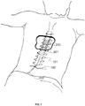
- FIG. 1 illustrates two wireless paddle leads 200 (described in more detail below) being implanted through an extended-width introducer 202 into the epidural space.
- a lead 200 may be advanced and guided into the epidural space utilizing the extension tubing 201 with a handle for manipulating the lead 200.
- the introducer 202 has an entry point 100 above lumbar spinal column 103 (shown in FIG. 2 ). Once the introducer 202 is removed, the wireless paddle lead 200 can be anchored in place subcutaneously at entry point 100. Thereafter, extension tubing 201 may remain implanted and may run from the skin placement to the wireless paddle leads 200.
- the tubing 201 contains a lumen for a stylet (otherwise referred to as an "injector lead wire,” a “guide-wire,” a “navigation wire,” or “a steer wire”), which can be used for placing the lead 200.
- the stylet may be made of metal and can provide steerability strength during implantation of the wireless paddle lead 200. After the wireless paddle lead 200 has been successfully deployed, the metal stylet may be removed. As will be discussed in association with FIG. 7C , this lumen, or other lumens in tubing 201, can be used to also house electronic circuitry.
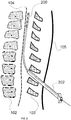
- FIG. 2 illustrates a wireless paddle lead 200 being placed through an introducer 202 typically in the lumbar region in between the L1 and L2 vertebrae.
- the introducer 202 may be inserted through a small incision in the skin 105 and in between the vertebrae 103.
- multiple wireless paddle leads 200, wireless cylindrical leads 400 (as will be discussed in association with FIGS. 8-15 ) and wireless semi-cylindrical leads 300 (as will be discussed in association with FIGS. 8-15 ) can be inserted through the same channel of introducer 202.
- Wireless paddle leads 200, cylindrical leads 400 or semi-cylindrical leads 300 for spinal cord stimulation applications can then be implanted and placed against the dura 104 of the spinal column 102, as described in association with FIG. 3 below.
- wireless paddle leads 200, cylindrical leads 400 or semi-cylindrical leads 300 may be adapted to be located within the epidural space of the spinal column, near or on the dura of the spinal column, in tissue in close proximity to the spinal column, in tissue located near the dorsal horn, dorsal root ganglia, dorsal roots, dorsal column fibers and/or peripheral nerve bundles leaving the dorsal column of the spine.
- wireless paddle leads 200, cylindrical leads 400 or semi-cylindrical leads 300 can be adapted to be placed and secured to stimulate nerves leaving the spinal column for the treatment of a variety of conditions, such as, for example, pain, angina, peripheral vascular disease, gastrointestinal disorders.
- wireless paddle leads 200 can be adapted to treat other conditions via neural stimulation of nerve bundles emanating from the spine.
- "Spinal cord tissue" and “nerve bundles emanating from the spine” generally refer to, without limitation, the nerve bundles ranging from spinal column levels C1 to L5, dorsal horn, dorsal root ganglia, dorsal roots, dorsal column fibers and peripheral nerve bundles leaving the dorsal column.
- FIG. 3 illustrates a wireless paddle lead 200 in place against the dura 104 of the spinal cord after being implanted into the human body for spinal cord stimulation applications.
- the small incision at the skin 105 can be stitched with a suture or sterile strip after placement of the anchoring mechanism 106.
- Wireless paddle leads shown here may have electrodes that confine the current path in a direction generally perpendicular to the dura, as will be discussed in association with FIG. 11C . This directionality may be desirable to zero in on a target particular tissue and to reduce electrical charges for efficacious stimulation.
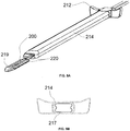
- FIGS. 4A illustrates an example of an introducer 214 that can fit in between two vertebrae without the need for a surgical laminotomy or removal of any bone tissue.
- the introducer 214 includes a handle 212 for use by the medical staff during the insertion procedure.
- the width of each handle can be between about 8 mm and about 15 mm.
- the length of each handle can be between about 10 mm and about 18 mm.
- the thickness of the handle may be between about 2.5mm and about 6 mm.
- the introducer 214 has an inner channel 215 that can house, for example, two wireless paddle leads 200 placed one at a time, sequentially through the same introducer channel. As illustrated, the example wireless paddle lead 200 can have a flat tip.
- FIG. 4B shows a cross-sectional view of the introducer illustrated in FIG. 4A .
- This cross-sectional view may also be known as a profile view.
- FIG. 5A illustrates another example introducer 214 that can fit through the vertebrae without the need for a surgical laminotomy or removal of any bone tissue.
- the introducer 214 includes a handle 212 for use by the medical staff during the insertion procedure.
- the introducer 214 has an inner channel 217 that can house, for example, two slim factor wireless paddle leads 220 placed one on top of the other.
- the two slim factor wireless paddle leads 220 can be stacked vertically in the inner channel 217 at the same time.
- the example wireless paddle lead 220 can have a pointed tip 219 that aids in directing the paddle lead through the tight epidural space of a smaller patient.
- the example wireless paddle lead 220 can also have a flat tip that aids in laying the electrode columns parallel with the spine from a fluoroscopic view or rounded tip that aids in both laying the electrode columns parallel with the spine and in directing the paddle lead through the epidural space.
- FIG. 5B shows a cross-sectional view of the introducer illustrated in FIG. 5A .
- This cross-sectional view may also be known as a profile view.
- FIG. 6A illustrates the distal tip of a wireless paddle lead 200.
- the wireless paddle lead 200 may include, for example, four electrodes 203 and the spacers between the electrodes.
- the wireless paddle lead 200 can include between two to sixteen electrodes 203 located on the distal end of the lead (not shown).
- the distal tip may have a height of between about 1.3 mm and about 2.0 mm, and a width between about 2.0 mm and about 4.0 mm.
- the electrodes 203 may have a longitudinal length between about 1.0 mm and about 6.0 mm from the distal tip toward the proximal tip and a width of between about 0.4mm and about 3.0 mm.
- the total electrode surface area of the lead 200 may be between about 0.8 mm 2 and about 60.0 mm 2 .
- the spacing between the electrodes 203 may be between about 1 mm and about 6 mm from distal to proximal.
- the various leads described herein may include anywhere from one to sixteen electrodes, any of which can be designated by the programmer as either a cathode or an anode.
- electrodes 203 can include multiple cathodes coupled to the targeted tissue as well as at least one anode.
- the electrode array can receive electrical stimulation waveform pulses ranging from 0 to 10V peak amplitude at a pulse width reaching up to a maximum of 1 millisecond.
- the polarity of the electrodes can produce various volume conduction distributions from the cathodes to the anodes to inhibit or excite surrounding nerve tissue, which may include A- ⁇ and/or primary or secondary c-fiber afferents.
- the electrodes may be made of a conductive, corrosion resistant, biocompatible material such as, for example, platinum, platinum-iridium, gallium-nitride, titanium-nitride, or iridium-oxide.
- the remaining portions of the wireless lead embodiments described herein may be insulated from surrounding body tissue partially or totally by an external coating layer of biocompatible dielectric material with a low dielectric constant.
- materials with rigidity similar to that of tissue can be used to reduce the risk of migration and the development of fibrous scar tissue.
- fibrous scar tissue can increase electrode-tissue impedance. If the electrode-tissue impedance can be kept low, less energy may be consumed to achieve stimulation of the targeted tissues.
- the wireless paddle lead 200 can have a rounded tip 211 at the distal end.
- Rounded tip 211 can be a non-conductive tip.
- Rounded tip 211 can have a length of between 0.5 mm and 2.0 mm, and a smooth finish for navigating the lead through the epidural space.
- the wireless paddle lead 200 can have a pointed tip 219 at the distal end.
- Pointed tip 219 can be a non-conductive tip.
- Pointed tip 219 can have a length of between about 2.0 mm and about 6.0 mm. Pointed tip 219 can enhance the steering capability when the wireless paddle 200 is being deployed.
- FIG. 6B shows the cross-sectional views of the distal end of three embodiments of a wireless paddle lead.
- the wireless paddle lead 200 may be a slim factor wireless paddle lead 220.
- the slim factor wireless paddle lead 220 can be thinner than a regular wireless paddle lead 221.
- slim-factor wireless paddle lead may be between about 1.0 mm and about 1.3 mm in height, which can allow multiple slim-factor wireless paddle leads to be implanted simultaneously or sequentially through an introducer 214.
- wireless paddle leads 200 may be a slim-factor concave wireless paddle lead 207 having a concave profile of between about 1.0 mm and 1.5 mm, concave edges of about 0.2 mm by about 0.3 mm.
- the concave profile may refer to the height of the slim-factor concave wireless paddle lead 207.
- the concave edge may refer to the dimension of the concave shape corner the slim-factor concave wireless paddle lead 207.
- the slim factor concave wireless paddle lead 207 may be placed as close as possible to the dorsal spinal column.
- At least one additional wireless lead may be placed in parallel or offset with the initial wireless lead.
- the wireless leads may be activated sequentially. In other embodiments, wireless leads can be activated simultaneously.
- FIGS. 7A and 7B respectively illustrate the dorsal and ventral sides of an implementation of a wireless paddle lead 200.
- electrodes 203 and between two to eight antenna coupling contacts 222 may be placed on different sides of the wireless paddle lead 200.
- two to sixteen electrodes 203 can be located on the distal end and embedded into the electrically insulative material 205 of the wireless lead 200.
- antenna 208 may be coupled to tissue through the antenna coupling contacts 222 located on the ventral side of the wireless paddle lead 200.
- the antenna can be, for example, a dipole antenna. Some embodiments may have only one dipole antenna, other embodiments may have multiple antennas of any given length. For example, without limitation, some embodiments may have between two and ten dipole antennas, while other embodiments can have more than ten dipole antennas or more than twenty dipole antennas.
- a dipole antenna can range from about 100 microns to about 10 cm in length. In other embodiments, an antenna can consist of any linear dipole configuration ranging from about 20 microns to about 3 mm in thickness.
- the antenna 208 may also be a folded dipole antenna instead of straight dipole antenna.
- Antenna 208 may be configured to receive RF energy from exterior antennas.
- RF wave propagation energy is divided into two regions, the radiative region and the reactive region.
- the radiative region is within 2D 2 / ⁇ and the radiated power varies with distance from the antenna.
- the reactive component is approximately ⁇ /2 ⁇ .
- the induced field for antennas placed in biological tissue is a function of body geometry, tissue properties, and the exposure conditions.
- the efficiency of the RF waveform inside a lossy media, such as body tissue is attenuated by the tissue as it propagates.
- the dipole antenna configuration can be optimized at high frequencies to minimize losses, such as, for example, from about 800 MHz to 5.8 GHz or greater.
- the antenna coupling contacts 222 in certain embodiments may have a longitudinal length between about 1.0 mm and about 6.0 mm from the distal tip toward the proximal tip and a width of between about 1.0 mm to about 2.5 mm.
- the spacing between the antenna coupling contacts 222 may be between about 30 mm and about 80 mm.
- the antenna coupling contracts 222 may improve the efficiency of the radiative coupling between internal antenna 208 and the antenna(s) (not depicted) located externally to the body.
- the antenna coupling contracts 222 may be made of noncorrosive metals, such as, for example, platinum, platinum-iridium, gallium-nitride, titanium-nitride, or iridium-oxide.
- Waveform conditioning circuitry 209 may include, for example electronic components such as, for example diodes, resistors and capacitors. Waveform conditioning circuitry 209 can use the incoming energy to provide a stimulation waveform to the electrodes for excitation of nerve tissue. In some embodiments, frequencies from about 800 MHz to about 5.8 GHz may be received by the implanted antenna 208. The stimulating waveform released into the tissue from electrodes 203 is rectified to provide waveforms at lower frequencies, e.g., at typically from about 5 Hz to about 1000 Hz.
- Waveform conditioning circuitry 209 is configured to rectify the waveform signal received by implanted antenna 208. Waveform conditioning circuitry 209 may also have charge balance microelectronics to prevent the corrosion of the electrodes. To minimize reflection of the energy back from the electrodes into the circuitry, waveform-conditioning circuitry 209 may include isolation circuits to block high frequency signals.
- FIG. 7C illustrates the ventral side of another embodiment of a wireless paddle lead 200, in which the implanted antenna 208 is separated from the distal end 205 of wireless paddle lead 200.
- the implanted antenna 208 may be placed remotely from the distal end 205 of the wireless paddle lead 200 and inside a lumen in extension tubing 201 within the lead body.
- the implanted antenna 208 may be the extension line of one of the antenna coupling contacts 304.
- antenna coupling contacts 304 may be located proximal to the electrodes 203.
- Antennas 208 may be further connected to the waveform conditioning circuitry 209 via shielded wiring 210.
- the waveform conditioning circuitry 209 may be directly wired to the electrodes 203 (located on the ventral side).
- the wireless leads described herein may have multiple layers. These layers can include, without limitation, encasing material close to the electrodes with a biocompatible compound that elicits minimal scar tissue formation.
- layers may include polymers such as, without limitation, polymethymethacrylate (PMMA), polydimethylsiloxane (PDMS), parylene, polyurethane, polytetrafluoroethylene (PTFE), or polycarbonate.
- PMMA polymethymethacrylate
- PDMS polydimethylsiloxane
- parylene polyurethane
- polytetrafluoroethylene (PTFE) polytetrafluoroethylene
- Another layer of a material that may be included contains a small relative permeability and low conductivity located above the antennas 208 to allow for optimal coupling with an exterior antenna (not depicted).
- Yet another layer can comprise a coating of a silicone elastomer to assist in preventing migration of the wireless lead to the surrounding tissue.
- FIGS. 8 and 9 illustrates an example of a wireless cylindrical lead 400 or a wireless semi-cylindrical lead 300 being implanted in the epidural space using needles 301.
- Cylindrical wireless leads may also be referred to as circumferential leads, while semi-cylindrical wireless leads may also be referred to as semi-circumferential or semi-elliptical wireless leads.
- Wireless cylindrical leads 400 or wireless semi-cylindrical leads 300 can be introduced into the body through needle 301.
- the needle 301 may be a tuohy needle, 14-Gauge, or smaller (for example, 22 Gauge).
- the wireless leads 300 and 400 may be introduced into the epidural space through an introducer 202 (see, for example, Fig. 1 ).
- Introducers 202 or needle 301 may be inserted through the outer skin of the body through a small incision in the skin 105 and in between the vertebrae 103 at no more than a 45-degree angle, lateral to the spinous processes off the midline, and placed against the dura 104 of the spinal column 102 to lie perpendicularly to the spinal cord.
- the wireless leads 300 or 400 can contain extension tubings 201 that terminate just under the entry point 100 of the skin.
- the wireless lead may be guided upwards in the epidural space according to the angle of introducer or needle insertion. After the wireless lead has been placed, a subcutaneous anchor is used to stop vertical and horizontal migration of the wireless lead.
- FIG. 10 illustrates embodiments of a cylindrical wireless lead 300 or semi-cylindrical wireless lead 400 after being implanted.
- a cylindrical 300 or semi-cylindrical 400 wireless lead may be placed against the dura 104 of the spinal cord and the small incision at the skin 105 is stitched with a suture or sterile strip after placement of the anchoring mechanism 106.
- FIG. 11A-11C respectively illustrate the cross-sectional views of the placement of a wireless semi-cylindrical lead 300, a wireless cylindrical lead 400, and a wireless paddle lead 200 after successful implantation in relation to the dura 104 of the spinal cord 101.
- FIG. 11A shows the placement of a wireless semi-cylindrical lead 300 relative to the dura 104 of the spinal cord 101.
- the wireless semi-cylindrical (also referred to as half-circumferential or half-elliptical) lead 300 may have electrodes that are straight, as depicted in FIG. 12A , or that are concave and half-cylindrical in shape.
- Semi-cylindrical electrodes can match the shape of the enclosure.
- the semi-cylindrical shape of the enclosure of lead 300 may help the lead to mechanically conform to the contour of the spinal column 102.
- the shape of the enclosure can also assist in targeting the electrical volume conduction inward towards the dura 104, and avoid radiating energy outwards towards the ligaments, vertebrae and skin (non-excitable tissue). More generally, the conducting field generated by the electrodes is uni-directional in nature because the conducting field culminates mainly in the enclosure and electrode faces are pointed in one direction. By removing the unnecessary emission from over 270 degrees of a cylindrical electrode (see, for example, in FIGS. 14B and 15 ) radiating towards non-excitable tissue, the semi-cylindrical wireless lead 300 can reduce the amount of energy required for a successful stimulation. Therefore, the benefits of the example semi-cylindrical wireless lead 300 may include the directional delivery of stimulation energy as confined by the shape of the electrode.
- FIG. 11B shows the placement of a wireless cylindrical lead 400 relative to the dura 104 of the spinal cord 101 after successful implantation. As depicted, the wireless cylindrical lead 400 is placed against dura 104.
- FIG. 11C shows the placement of a wireless paddle lead 200 relative to the dura 104 of the spinal cord 101 after successful implantation.
- the wireless paddle lead 200 is placed against dura 104.
- Wireless paddle lead 200 may have electrodes that confine the current path in a direction generally perpendicular to the dura. This directionality may be desirable to zero in on a target particular tissue and to reduce electrical charges for efficacious stimulation
- FIGS. 12A and 12B illustrate perspective and profile views, respectively, of an implementation of a wireless semi-cylindrical lead 300.
- the semi-cylindrical lead 300 can have, in certain embodiments between two to sixteen electrodes 203 at the distal end 205, each with a diameter typically between about 0.8 mm and about 1.4 mm, and concave ventral aspects with bend radiuses typically between about 0.6 mm and about 3.0 mm.
- the electrodes 203 may have longitudinal lengths between about 1.0 mm and about 6.0 mm from the distal tip towards the proximal tip with widths typically between about 0.4 mm and about 1.0 mm.
- the total electrode surface area of the wireless lead 300 is typically between about 0.8 mm 2 and about 60.0 mm 2 .
- the spacing between the electrode contacts is typically between about 1.0 mm and about 6.0 mm.
- the distal tip of the lead body may be a non-conductive tip that is pointed with a length of between about 0.5 mm and about 2.0 mm, and a smooth finish for navigating the lead through the epidural space.
- the wireless semi-cylindrical lead 300 may include between two to eight antenna coupling contacts 304, as illustrated in association with FIG. 7C , that are wired to the implanted antenna(s) 208 and the flexible circuits 206 (as illustrated in association with FIGS. 12 and 13 ).
- the antenna coupling contacts 304 may be proximal of the electrodes 203.
- the antenna coupling pads 304 may have a longitudinal length of between about 1 mm and about 6 mm from the distal tip to the proximal tip.
- the spacing between the antenna coupling contacts 304 is typically between 30 mm and 80 mm.
- small antenna coupling contacts 303 to be discussed in association with FIG. 13C , may be used.
- Antenna coupling contacts 303 may have a diameter between about 0.2 mm and about 0.6 mm.
- Embodiments of wireless leads described herein can have a larger surface area directed towards the dura mater than existing percutaneous leads. This increased surface area can lower the tissue to electrode impedance values and can lead to larger currents for stimulation.
- FIGS. 13A-13C variously illustrate electronic components included in two different embodiments of the wireless lead, namely, a wireless semi-cylindrical lead 300 and a wireless cylindrical lead 400.
- FIG. 13A shows an example wireless lead (e.g. a wireless semi-cylindrical lead 300 or a wireless cylindrical lead 400 ) with extension tubing 201.
- the tubing 201 may house electrodes 203, implanted antenna 208, waveform conditioning circuitry 209, and wires 210.
- the waveform conditioning circuitry 209 can include components for rectifying the received RF energy and for charge balancing the waveform for tissue stimulation.
- the flexible circuits 206 may be used to carry various parts of the electronic components.
- the flexible circuits 206 may include the waveform conditioning circuitry 209 and implantable antenna(s) 208.
- the flex circuit may also include portions of the wires 210, which connect the electronics, such as circuitry 209, to the electrodes 203.
- the flexible circuits 206 may be between about 15 mm and about 90 mm long, and about 0.7 mm and about 2.0 mm wide.
- the total height of the flexible circuit 206 with the waveform conditioning circuitry 209 may be between about 0.2 mm and about 0.4 mm.
- the flexible circuit 206 when placed inside of the cylindrical wireless lead 400 may undergo a bend radius under about 0.5 mm.
- the flexible circuit 206 may contain a conductive trace to act as an antenna 208.
- FIG. 13B shows another example of a wireless lead (e.g. a wireless semi-cylindrical lead 300 and a wireless cylindrical lead 400 ) encapsulated that includes tubing 201.
- the tubing houses antenna(s) 208 and the waveform conditioning circuitry 209, both of which may be formed on a flex circuit 206 similar to the flex circuit described with respect to FIG. 13A .
- At least a portion of the wires 210 may be formed on the flex circuit as well.
- Wires 210 connect, for example, the circuitry 209 to the electrodes (not shown in FIG. 13B ).
- Wires 210 also connect the antenna 208 to tissue exposed ring antenna coupling contacts 304.
- Tissue exposed ring antenna coupling contacts 304 can be circumferential rings with outer diameter between about 0.8 mm and about 1.4 mm, and longitudinal lengths between about 0.5 mm and about 6.0 mm.
- FIG. 13C shows yet another example wireless lead (e.g. a wireless semi-cylindrical lead 300 and a wireless cylindrical lead 400 ) with extension tubing 201.
- the extension tubing 201 houses antenna(s) 208 and the waveform conditioning circuitry 209, both of which may be formed on a flex circuit 206 similar to the flex circuit described with respect to FIG. 13A .
- At least a portion of the wires 210 may be formed on the flex circuit as well.
- Wires 210 connect, for example, the circuitry 209 to the electrodes (not shown in FIG. 13C ).
- Wires 210 also connect the antenna 208 to tissue exposed small antenna coupling contacts 303.
- Tissue exposed small antenna coupling contacts 303 may be made of a conductive cylindrical piece of metal of diameter between about 0.2 mm and about 0.6 mm and thickness of between about 0.2 mm and about 0.6 mm. Tissue exposed small antenna coupling contacts 303 may contact tissue and can be embedded into the electrically insulative material 205.
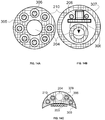
- FIG. 14A illustrates a cross-sectional view of an embodiment of a fully cylindrical wireless lead 400 or a semi-cylindrical wireless lead 300 at a position proximal to the distal tip.
- the embodiment shown is a multi-lumen extrusion 305 having a center lumen 204 and multiple orbital lumens 306 (for example, one to ten or more).
- the multi-lumen extrusion 305 may be proximal to the single-lumen extrusion 307, shown in the right graph, on one wireless lead (for example, a fully cylindrical wireless lead 400 or a semi-cylindrical wireless lead 300 ).
- the multi-lumen extrusion 305 may act as backbone for guiding the conducting wires 210, housed in side lumens 306, and a stylet (as discussed in association with Fig. 1 ) placed through the center lumen 204.
- the multi-lumen plastic extrusion 305 can be made up of between one to ten or more orbital lumens 306, each with inner diameters of between about 0.1 mm and about 0.6 mm.
- the multi-lumen plastic extrusion 305 may have an outer diameter of between about 0.8 mm and about 1.4 mm.
- the multi-lumen extrusion 305 may be ablated (i.e., heated to be deformed) to a final outer diameter of between about 0.6 mm and about 0.9 mm which allows the extrusion 305 to connect male to female into a single lumen extrusion 307, as shown in the right graph.
- a navigation stylet may be placed inside the inner lumen 204 to guide the wireless lead into the epidural space.
- the inner lumen 204 maintains a clear channel without obstruction and may be fused with the single lumen extrusion 307 at the interconnection between extrusions 305 and 307 and after the above-mentioned ablation.
- FIG. 14B illustrates a cross-sectional view of another embodiment of a fully cylindrical wireless lead 400 or a semi-cylindrical wireless lead 300 at a position proximal to the distal tip.
- This embodiment is a single-lumen extrusion 307, which may have inner diameter of between about 0.3 mm and about 1.4 mm.
- the single lumen extrusion 307 may be pulled around the outside of, for example, the wireless semi-cylindrical lead 300 and heat formed to match an outer diameter of between about 0.8 mm and about 1.4 mm.
- the single lumen extrusion 307 can leave sufficient empty space for the flexible circuit 206 to be encapsulated inside.
- the inner lumen 204 may be offset by a distance indicated by 308 inside the single lumen 307 to provide a gap space for the flexible circuit 206.
- Conducting wires 210 from the side lumens 306 may connect to terminal features (not depicted) on the flexible circuit 206.
- the gap space inside the single-lumen extrusion 307 between the flexible circuit 206 and inner lumen 204 may be back-filled with a biocompatible polymer to give added rigidity for protecting the flexible circuit components 206 and conducting wires 210.
- FIG. 14C illustrates a cross-sectional view towards the distal end of a semi-cylindrical wireless lead 300.
- the concave multi-lumen extrusion 309 may house the conducting wires 210 running from the flex circuit 206 to the electrodes 203.
- the concave shape of multi-lumen extrusion 309 may allow semi-cylindrical wireless lead 300 to conform to the curvature of the spinal cord.
- the bend radius of the concave dorsal aspect is between about 0.6 mm and about 3.0 mm.
- the concave multi-lumen extrusion 309 may contain between one and ten or more orbital lumens 306 acting as channels for conducting wires and a central lumen 204 for the stylet.
- the lumens 204 and 306 may have inner diameters of between 0.1 mm and 0.6 mm.
- the orbital lumens 306 may be drilled into from the dorsal side during manufacturing to create channels to connect the conducting wires 210 to the electrodes 203.
- Fig. 15 illustrates an example of a fully circumferential wireless lead.
- the cylindrical wireless lead 400 may have between two and sixteen cylindrical electrodes 203 on its distal end with a diameter between about 0.8 mm and about 1.4 mm for epidural spinal cord stimulation applications.
- the electrodes 203 may have a longitudinal length of between about 1.0 mm and about 6.0 mm from the distal tip toward the proximal tip.
- the spacing between the electrode contacts may be between about 1.0 mm and about 6.0 mm.
- the total electrode surface area of the cylindrical wireless lead body 400 may be between about 1.6 mm 2 and about 60.0 mm 2 .
- the distal tip of the cylindrical wireless lead body 400 may be a non-conductive tip that is rounded with a length of between about 0.5 mm and about 1.0 mm, with a smooth finish for navigating the lead through the epidural space.
- tissue exposed ring antenna coupling contacts 304 may be proximal to the electrodes 203.
- the tissue exposed circular antenna coupling contacts 304 may have a longitudinal length of between about 1.0 mm and about 6.0 mm from the distal tip toward the proximal tip.
- the spacing between the tissue-exposed circular antenna coupling contacts 304 may be between about 30 mm and about 80 mm.
- tissue exposed small antenna coupling contacts 303 with a diameter between about 0.2 mm and about 0.6 mm may be used in lieu of the illustrated tissue exposed small antenna coupling contacts 303.
- Extension tubing 201 can provide an enclosure that houses, for example, flex circuitry 206. Flex circuitry 206 has been discussed in association with FIGS 13A to 13C . Extension tubing 201 may include a center lumen 204. As discussed in association with FIG 14A , a stylet can be placed through center lumen 204 to provide guidance during implantation of lead 400 into, for example, through a lumen in to a human body.
- Various implementations of the technology may allow placement of wireless lead in the epidural space, between the dura mater and arachnoid membranes, or subdurally in the intrathecal space, where significant reactions and scarring would be minimized. Insertion in any of these locations may be done by injecting the device from a smaller gauge needle (e.g., 14 to 22-gauge needle or out of a cannula steered to the proper position by a removable stylet). In some implementations, once in position, no further skin incisions or placement of extensions, receivers or implanted pulse generators are needed.
- a smaller gauge needle e.g. 14 to 22-gauge needle or out of a cannula steered to the proper position by a removable stylet.
- Various implementations of the wireless neural modulation system may have significant advantages due to the small size and lack of extension wires for transfer of energy, allowing placement with minimal trauma and long term effective therapy in places where larger implantable devices could cause more scar tissue and tissue reactions that may affect efficacy and safety.
Landscapes
- Health & Medical Sciences (AREA)
- Radiology & Medical Imaging (AREA)
- Animal Behavior & Ethology (AREA)
- Veterinary Medicine (AREA)
- Public Health (AREA)
- General Health & Medical Sciences (AREA)
- Engineering & Computer Science (AREA)
- Biomedical Technology (AREA)
- Nuclear Medicine, Radiotherapy & Molecular Imaging (AREA)
- Life Sciences & Earth Sciences (AREA)
- Physics & Mathematics (AREA)
- Neurosurgery (AREA)
- Neurology (AREA)
- Electromagnetism (AREA)
- Acoustics & Sound (AREA)
- Heart & Thoracic Surgery (AREA)
- Pain & Pain Management (AREA)
- Cardiology (AREA)
- Orthopedic Medicine & Surgery (AREA)
- Electrotherapy Devices (AREA)
- Materials For Medical Uses (AREA)
- Thermistors And Varistors (AREA)
Claims (33)
- Implantierbare, funkbetätigte Neurostimulatorleitung, wobei die Leitung ein passiver Stimulator ist, der einen Durchmesser von weniger als 1,3 mm aufweist, wobei die Leitung frei ist von einer Induktionsspule und umfasst:
ein Gehäuse, das ein Vorschubrohr (201) mit einem Lumen (204) aufweist, wobei das Lumen die Handhabung eines Navigationsmandrins während des Einsetzens des Gehäuses ermöglicht, wobei in dem Gehäuse Folgendes untergebracht ist:- eine oder mehrere Elektroden (203), die so konfiguriert sind, dass sie einen oder mehrere elektrische Impulse an Nervengewebe anlegen;- eine erste Antenne (208), wobei die erste Antenne eine Dipolantenne ist, die für Folgendes konfiguriert ist: Empfangen eines Eingangssignals, das elektrische Energie enthält, von einer zweiten Antenne und durch elektrische Strahlungskopplung, wobei die zweite Antenne physisch von der implantierbaren Neurostimulatorleitung getrennt ist;- einen oder mehrere Stromkreise (209), die elektrisch mit der ersten Antenne verbunden sind, wobei die Stromkreise (209) für Folgendes konfiguriert sind:• Erzeugen eines oder mehrerer elektrischer Impulse, die sich für die Stimulation des Nervengewebes unter Verwendung der in dem Eingangssignal enthaltenen elektrischen Energie eignen; und• Liefern des einen oder der mehreren elektrischen Impulse an die eine oder die mehreren Elektroden, wobei das Gehäuse so geformt und angeordnet ist, dass es durch eine Schleuse oder eine Kanüle (214) in den Körper eines Patienten eingesetzt werden kann. - Leitung nach Anspruch 1, wobei ein Abschnitt des Gehäuses die Elektroden in indirektem Kontakt mit dem Nervengewebe lässt, nachdem die Leitung in den Körper des Patienten eingesetzt wurde.
- Leitung nach Anspruch 1, wobei das Gehäuse von halbzylindrischer Form ist und die eine oder die mehreren Elektroden mindestens eine Lenkungselektrode beinhaltet, deren Form dafür ausgelegt ist, ein unidirektionales leitendes Feld zu erzeugen.
- Leitung nach Anspruch 3, wobei die eine oder die mehreren Elektroden eine halbzylindrische Anordnung von Elektroden beinhalten.
- Leitung nach Anspruch 1, wobei die Elektroden aus mindestens einem der folgenden Materialien gemacht sind: Platin, Platin-Iridium, Galliumnitrid, Titannitrid, Iridiumoxid oder Kombinationen davon.
- Leitung nach Anspruch 1, wobei die Elektroden zwei bis sechzehn Elektroden beinhalten, die jeweils eine Längsabmessung zwischen 1,0 und 6,0 mm und eine Breite zwischen 0,4 und 3,0 mm aufweisen.
- Leitung nach Anspruch 5, wobei die Elektroden zwischen 1 mm und 6 mm voneinander beabstandet sind und einen kombinierten Oberflächeninhalt zwischen 0,8 mm und 60,00 mm aufweisen.
- System nach Anspruch 1, wobei die Leitung eine paddelartige Leitung ist.
- Leitung nach Anspruch 8, wobei die Leitung eine Höhe zwischen 1,3 mm und 2,0 mm und eine Breite zwischen 2,0 mm und 4,0 mm aufweist.
- Leitung nach Anspruch 8, wobei die Leitung konkav geformt ist, um eine laterale Position am Nervengewebe zu gewährleisten, nachdem die Leitung in den Körper des Patienten eingesetzt wurde.
- Leitung nach Anspruch 10, wobei die Leitung ein konkaves Profil zwischen 1,0 mm und 1,5 mm und einen konkaven Rand zwischen 0,2 mm und 0,3 mm aufweist.
- Leitung nach Anspruch 1, wobei die Kanüle eine Epiduralkanüle ist.
- Leitung nach Anspruch 1, wobei die Kanüle nicht länger ist als 1,63 mm.
- Leitung nach Anspruch 1, ferner ein distales vorderes Ende aufweisend.
- Leitung nach Anspruch 14, wobei das distale vordere Ende mit einer Länge zwischen 0,5 und 2,0 mm abgerundet ist.
- Leitung nach Anspruch 14, wobei das distale vordere Ende mit einer Länge zwischen 2,0 und 6,0 mm zugespitzt ist.
- Leitung nach Anspruch 1, wobei das Gehäuse eine äußere Beschichtung aus biokompatiblem Polymer aufweist, wobei das Polymer mindestens eines der folgenden beinhaltet: Polymethylmethacrylat (PMMA), Polydimethylsiloxan (PDMS), Parylen, Polyurethan, Polytetrafluorethylen (PTFE) oder Polycarbonat.
- Leitung nach Anspruch 1, wobei das Gehäuse ferner eine äußere Beschichtung aus Silikonelastomer aufweist.
- Leitung nach Anspruch 1, wobei in dem Gehäuse ferner Antennenkopplungskontakte (222) untergebracht sind, wobei die Antennenkontakte elektrisch mit den Antennen und den Stromkreisen (209) verbunden sind und so konfiguriert sind, dass sie die Antenne mit dem umgebenden Gewebe koppeln.
- Leitung nach Anspruch 19, wobei die Antennenkopplungskontakte zwei bis acht Antennenkopplungspaare beinhalten.
- Leitung nach Anspruch 19, wobei die Antennenkopplungskontakte proximal in Bezug auf die Elektroden in dem Gehäuse angeordnet sind.
- Leitung nach Anspruch 19, wobei die Antennenkopplungskontakte jeweils eine Längsabmessung zwischen 1,0 mm und 6,0 mm und eine Breite zwischen 1,0 mm und 2,5 mm aufweisen.
- Leitung nach Anspruch 19, wobei die Antennenkopplungskontakte zwischen 30 mm und 80 mm voneinander beabstandet sind.
- Leitung nach Anspruch 1, wobei die erste Antenne als Leiterbahn aufgebaut ist, die an einem der Stromkreise enthalten ist.
- Leitung nach Anspruch 1, wobei die erste Antenne als Leitungsdraht gefertigt ist, der mit einem der Stromkreise verbunden ist.
- Leitung nach Anspruch 1, wobei die Stromkreise flexible Stromkreise sind.
- Leitung nach Anspruch 26, wobei die flexiblen Stromkreise einem Biegeradius von unter 0,5 mm unterworfen werden können.
- Leitung nach Anspruch 26, wobei die flexiblen Stromkreise proximal in Bezug auf die Elektroden in dem Gehäuse angeordnet sind.
- Leitung nach Anspruch 26, wobei die flexiblen Stromkreise eine Wellenformkonditionierungsschaltung (209) aufweisen.
- Leitung nach Anspruch 29, wobei in dem Gehäuse ferner die Antennenkopplungskontakte (222) nach Anspruch 19 untergebracht sind, wobei die Antennenkopplungskontakte (222) durch Verbindungsdrähte (210) mit der Antenne (208) und der Wellenformkonditionierungsschaltung (209) verbunden sind, wobei die Wellenformkonditionierungsschaltung ankommende Energie verwendet, um eine Stimulationswellenform zur Erregung von Nervengewebe an den Elektroden bereitzustellen.
- Leitung nach Anspruch 30, wobei die Wellenformkonditionierungsschaltung (209) Dioden, Widerstände und/oder Kondensatoren beinhaltet.
- Leitung nach Anspruch 30, wobei die Wellenformkonditionierungsschaltung (209) Ladungsausgleichsmikroelektronik umfasst, um die Korrosion der Elektroden zu verhindern.
- Leitung nach Anspruch 27, wobei die Wellenformkonditionierungsschaltung (209) Trennstromkreise umfasst.
Priority Applications (1)
| Application Number | Priority Date | Filing Date | Title |
|---|---|---|---|
| EP19186209.3A EP3586908A1 (de) | 2011-04-04 | 2012-04-04 | Implantierbarer neurostimulator mit drahtloser schnittstelle |
Applications Claiming Priority (2)
| Application Number | Priority Date | Filing Date | Title |
|---|---|---|---|
| US201161471496P | 2011-04-04 | 2011-04-04 | |
| PCT/US2012/032200 WO2012138782A1 (en) | 2011-04-04 | 2012-04-04 | Implantable lead |
Related Child Applications (1)
| Application Number | Title | Priority Date | Filing Date |
|---|---|---|---|
| EP19186209.3A Division EP3586908A1 (de) | 2011-04-04 | 2012-04-04 | Implantierbarer neurostimulator mit drahtloser schnittstelle |
Publications (3)
| Publication Number | Publication Date |
|---|---|
| EP2694154A1 EP2694154A1 (de) | 2014-02-12 |
| EP2694154A4 EP2694154A4 (de) | 2014-12-10 |
| EP2694154B1 true EP2694154B1 (de) | 2019-07-17 |
Family
ID=46969537
Family Applications (2)
| Application Number | Title | Priority Date | Filing Date |
|---|---|---|---|
| EP12767575.9A Active EP2694154B1 (de) | 2011-04-04 | 2012-04-04 | Implantierbare leitung |
| EP19186209.3A Pending EP3586908A1 (de) | 2011-04-04 | 2012-04-04 | Implantierbarer neurostimulator mit drahtloser schnittstelle |
Family Applications After (1)
| Application Number | Title | Priority Date | Filing Date |
|---|---|---|---|
| EP19186209.3A Pending EP3586908A1 (de) | 2011-04-04 | 2012-04-04 | Implantierbarer neurostimulator mit drahtloser schnittstelle |
Country Status (10)
| Country | Link |
|---|---|
| US (3) | US10953228B2 (de) |
| EP (2) | EP2694154B1 (de) |
| JP (2) | JP6671843B2 (de) |
| CN (2) | CN110013606B (de) |
| AU (1) | AU2012240239B2 (de) |
| BR (1) | BR112013025521B1 (de) |
| CA (1) | CA2831138C (de) |
| IL (2) | IL228485B (de) |
| MX (1) | MX346885B (de) |
| WO (1) | WO2012138782A1 (de) |
Cited By (1)
| Publication number | Priority date | Publication date | Assignee | Title |
|---|---|---|---|---|
| US12115374B2 (en) | 2011-01-28 | 2024-10-15 | Curonix Llc | Microwave field stimulator |
Families Citing this family (63)
| Publication number | Priority date | Publication date | Assignee | Title |
|---|---|---|---|---|
| WO2006087712A2 (en) | 2005-02-17 | 2006-08-24 | Metacure N.V. | Charger with data transfer capabilities |
| CA2831062A1 (en) | 2011-01-28 | 2012-08-02 | Stimwave Technologies Incorporated | Neural stimulator system |
| US8849412B2 (en) | 2011-01-28 | 2014-09-30 | Micron Devices Llc | Microwave field stimulator |
| EP2694154B1 (de) | 2011-04-04 | 2019-07-17 | Micron Devices LLC | Implantierbare leitung |
| US9220897B2 (en) | 2011-04-04 | 2015-12-29 | Micron Devices Llc | Implantable lead |
| US11413458B2 (en) | 2011-05-19 | 2022-08-16 | Neuros Medical, Inc. | Nerve cuff electrode for neuromodulation in large human nerve trunks |
| CN107789730B (zh) | 2011-07-29 | 2020-11-10 | 米克伦设备有限责任公司 | 用于神经刺激器的功率或极性选择的远程控制 |
| EP2755718B8 (de) | 2011-09-15 | 2018-06-06 | Micron Devices LLC | Relaismodul für ein implantat |
| US10463858B2 (en) | 2012-07-17 | 2019-11-05 | Stimwave Technologies Incorporated | Devices and methods for treating craniofacial pain |
| US9623253B2 (en) | 2012-07-17 | 2017-04-18 | Micron Devices, LLC | Devices and methods for treating urological disorders |
| US10245436B2 (en) | 2012-07-17 | 2019-04-02 | Stimwave Technologies Incorporated | Miniature implantable device and methods |
| WO2014153228A1 (en) * | 2013-03-14 | 2014-09-25 | Perryman Laura Tyler | Miniature implantable device and methods |
| BR112015013077B1 (pt) * | 2012-12-05 | 2022-02-08 | Micron Devices Llc | Dispositivo para fornecer uma sonda implantável com energia sem fio e sistema e método para modular tecido excitável em um corpo de um paciente |
| WO2014105973A1 (en) | 2012-12-26 | 2014-07-03 | Micron Devices, LLC | Wearable antenna assembly |
| CN105163800B (zh) | 2013-03-14 | 2019-05-14 | 微米器件有限责任公司 | 无线可植入电力接收器系统和方法 |
| WO2015003015A2 (en) * | 2013-07-01 | 2015-01-08 | Intersection Medical, Inc. | Compact and wearable apparatuses for home use in determining tissue wetness |
| WO2015004673A1 (en) * | 2013-07-11 | 2015-01-15 | Newpace Ltd. | Battery and electronics integration in an implantable medical device |
| US10610693B2 (en) | 2013-07-11 | 2020-04-07 | Newpace Ltd. | Battery and electronics integration in a flexible implantable medical device |
| US8831747B1 (en) | 2013-11-19 | 2014-09-09 | Pacesetter, Inc. | Leadless neurostimulation device and method including the same |
| EP3082575A2 (de) * | 2013-12-19 | 2016-10-26 | Cardiac Pacemakers, Inc. | System und verfahren zur ortung von neuralem gewebe |
| US10245435B1 (en) * | 2014-01-06 | 2019-04-02 | Stimwave Technologies Incorporated | Wireless neural stimulator implantation |
| WO2015175572A1 (en) | 2014-05-12 | 2015-11-19 | Micron Devices Llc | Remote rf power system with low profile transmitting antenna |
| US10265530B1 (en) | 2014-05-29 | 2019-04-23 | Stimwave Technologies Incorporated | Simulation with electrode arrays |
| EP3166682B1 (de) | 2014-07-10 | 2021-01-06 | Stimwave Technologies Incorporated | Schaltung für eine implantierbare vorrichtung |
| US10369365B2 (en) | 2014-11-26 | 2019-08-06 | Stimwave Technologies Incorporated | Controller interface for an implantable stimulator device |
| WO2016109836A2 (en) | 2014-12-31 | 2016-07-07 | Chad David Andresen | Antenna assembly |
| WO2016109833A1 (en) | 2014-12-31 | 2016-07-07 | Chad David Andresen | Patch antenna assembly |
| US9956393B2 (en) | 2015-02-24 | 2018-05-01 | Elira, Inc. | Systems for increasing a delay in the gastric emptying time for a patient using a transcutaneous electro-dermal patch |
| US20220062621A1 (en) | 2015-02-24 | 2022-03-03 | Elira, Inc. | Electrical Stimulation-Based Weight Management System |
| US10376145B2 (en) | 2015-02-24 | 2019-08-13 | Elira, Inc. | Systems and methods for enabling a patient to achieve a weight loss objective using an electrical dermal patch |
| US10765863B2 (en) | 2015-02-24 | 2020-09-08 | Elira, Inc. | Systems and methods for using a transcutaneous electrical stimulation device to deliver titrated therapy |
| EP3261712B1 (de) | 2015-02-24 | 2024-04-03 | Elira, Inc. | System zur appetitmodulation und/oder verbesserung der ernährungseinhaltung mithilfe eines elektrohautpflasters |
| US10335302B2 (en) | 2015-02-24 | 2019-07-02 | Elira, Inc. | Systems and methods for using transcutaneous electrical stimulation to enable dietary interventions |
| US10864367B2 (en) | 2015-02-24 | 2020-12-15 | Elira, Inc. | Methods for using an electrical dermal patch in a manner that reduces adverse patient reactions |
| US10149976B1 (en) | 2015-03-06 | 2018-12-11 | Micron Devices Llc | Placement of neural stimulators |
| US10092755B1 (en) | 2015-03-09 | 2018-10-09 | Micro Devices Llc | Neural stimulator placement |
| US10272239B1 (en) | 2015-03-10 | 2019-04-30 | Stimwave Technologies Incorporated | Neural stimulator placement |
| US10737098B2 (en) | 2015-06-22 | 2020-08-11 | Stimwave Technologies Incorporated | Earpiece assembly to interact with implantable neural stimulators |
| US10188866B2 (en) | 2015-06-24 | 2019-01-29 | Impulse Dynamics Nv | Simple control of complex bio-implants |
| US9630012B2 (en) | 2015-08-06 | 2017-04-25 | Meagan Medical, Inc. | Spinal cord stimulation with interferential current |
| US10420950B2 (en) | 2015-11-29 | 2019-09-24 | Boston Scientific Neuromodulation Corporation | Implantable pulse generator usable during a trial stimulation phase and externally powered by magnetic inductive coupling |
| US10576292B2 (en) | 2015-11-29 | 2020-03-03 | Boston Scientific Neuromodulation Corporation | Skull-mounted deep brain stimulator |
| AU2017208022B2 (en) * | 2016-01-15 | 2021-12-02 | Tva Medical, Inc. | Systems and methods for adhering vessels |
| EP3402567B1 (de) | 2016-01-15 | 2022-03-09 | Stimwave Technologies Incorporated | Implantierbares relaismodul |
| US10646164B1 (en) | 2016-05-24 | 2020-05-12 | Stimwave Technologies Incorporated | Pulse-density modulation to synthesize stimulation waveforms on an implantable device |
| US10632314B1 (en) | 2016-06-10 | 2020-04-28 | Stimwave Technologies Incorporated | User interface for a patient user to adjust settings on an implantable device |
| ES2841305T3 (es) | 2016-07-07 | 2021-07-08 | Univ California | Implantes que usan ondas ultrasónicas para estimular un tejido |
| US10541468B2 (en) | 2016-07-28 | 2020-01-21 | Stimwave Technologies Incorporated | Fabric antenna |
| US11166745B2 (en) | 2017-09-12 | 2021-11-09 | Jessica Jameson | Multi-port epidural needle |
| US11331500B1 (en) | 2017-11-20 | 2022-05-17 | Stimwave Technologies Incorporated | Systems and methods to locate an implantable stimulator device inside a subject |
| EP3723840B1 (de) | 2017-12-13 | 2022-11-30 | Neuros Medical, Inc. | Vorrichtung zum einsetzen einer nervenmanschette |
| WO2019199558A1 (en) | 2018-04-09 | 2019-10-17 | Neuros Medical, Inc. | Apparatuses and methods for setting an electrical dose |
| AU2019255373A1 (en) | 2018-04-19 | 2020-11-26 | Iota Biosciences, Inc. | Implants using ultrasonic communication for modulating splenic nerve activity |
| EP3781253A4 (de) | 2018-04-19 | 2022-02-16 | Iota Biosciences, Inc. | Implantate mit ultraschallkommunikation zur neuronalen abtastung und stimulation |
| AU2019267947A1 (en) * | 2018-05-11 | 2020-11-12 | Synerfuse, Inc. | System, devices, and methods combining spinal stabilization and neuromodulation |
| US11266841B1 (en) | 2018-06-01 | 2022-03-08 | Stimwave Technologies Incorporated | Securing antennas to wearable articles |
| EP3616748A1 (de) * | 2018-08-27 | 2020-03-04 | National University of Ireland, Galway | Implantierbarer neurostimulator |
| PL3843830T3 (pl) | 2018-08-29 | 2024-08-12 | Iota Biosciences, Inc. | Wszczepialne urządzenie do neuromodulacji w zamkniętej pętli |
| US11439832B2 (en) | 2019-01-09 | 2022-09-13 | Stimwave Technologies Incorporated | Implantable electronic devices |
| US11672990B2 (en) | 2019-01-15 | 2023-06-13 | Stimwave Technologies Incorporated | Headsets for positioning electronic devices |
| WO2021097342A1 (en) | 2019-11-13 | 2021-05-20 | Stimwave Technologies Incorporated | Manufacturing implantable tissue stimulators |
| AU2021219722A1 (en) | 2020-02-11 | 2022-09-08 | Neuros Medical, Inc. | System and method for quantifying qualitative patient-reported data sets |
| CN115072655B (zh) * | 2022-07-22 | 2022-11-11 | 中国电子科技集团公司第五十八研究所 | 一种生物兼容微螺线管的晶圆级制备方法 |
Citations (2)
| Publication number | Priority date | Publication date | Assignee | Title |
|---|---|---|---|---|
| US20030078633A1 (en) * | 2001-09-28 | 2003-04-24 | Firlik Andrew D. | Methods and implantable apparatus for electrical therapy |
| US20100269339A1 (en) * | 2009-04-24 | 2010-10-28 | Advanced Neuromodulation Systems, Inc. | Method of fabricating stimulation lead by fusing connector segment between lead body and electrode portion of the lead |
Family Cites Families (265)
| Publication number | Priority date | Publication date | Assignee | Title |
|---|---|---|---|---|
| US2990547A (en) | 1959-07-28 | 1961-06-27 | Boeing Co | Antenna structure |
| US3662758A (en) | 1969-06-30 | 1972-05-16 | Mentor Corp | Stimulator apparatus for muscular organs with external transmitter and implantable receiver |
| US3663758A (en) | 1970-03-24 | 1972-05-16 | Teaching Complements Inc | Speech pattern recognition system |
| US3727616A (en) | 1971-06-15 | 1973-04-17 | Gen Dynamics Corp | Electronic system for the stimulation of biological systems |
| FR2283590A1 (fr) | 1974-08-30 | 1976-03-26 | Commissariat Energie Atomique | Procede de stimulation nerveuse et stimulateur d'application du procede |
| US4102344A (en) | 1976-11-15 | 1978-07-25 | Mentor Corporation | Stimulator apparatus for internal body organ |
| US4223679A (en) | 1979-02-28 | 1980-09-23 | Pacesetter Systems, Inc. | Telemetry means for tissue stimulator system |
| US4612934A (en) | 1981-06-30 | 1986-09-23 | Borkan William N | Non-invasive multiprogrammable tissue stimulator |
| US4793353A (en) | 1981-06-30 | 1988-12-27 | Borkan William N | Non-invasive multiprogrammable tissue stimulator and method |
| DE3130104A1 (de) | 1981-07-30 | 1983-02-17 | Messerschmitt-Bölkow-Blohm GmbH, 8000 München | Anordnung zur stimulation eines menschlichen muskels |
| JPS5889075A (ja) | 1981-11-24 | 1983-05-27 | Hitachi Ltd | 共振形スイツチング電源装置 |
| US4494950A (en) | 1982-01-19 | 1985-01-22 | The Johns Hopkins University | Plural module medication delivery system |
| US4561443A (en) | 1983-03-08 | 1985-12-31 | The Johns Hopkins University | Coherent inductive communications link for biomedical applications |
| US4532930A (en) | 1983-04-11 | 1985-08-06 | Commonwealth Of Australia, Dept. Of Science & Technology | Cochlear implant system for an auditory prosthesis |
| AU569636B2 (en) | 1984-09-07 | 1988-02-11 | University Of Melbourne, The | Bipolar paired pulse supplied prosthetic device |
| CA1246680A (en) | 1984-10-22 | 1988-12-13 | James M. Harrison | Power transfer for implanted prosthesis |
| AU5481786A (en) | 1985-03-20 | 1986-09-25 | Hochmair, E.S. | Transcutaneous power and signal transmission system |
| US4592359A (en) | 1985-04-02 | 1986-06-03 | The Board Of Trustees Of The Leland Stanford Junior University | Multi-channel implantable neural stimulator |
| US4665896A (en) | 1985-07-22 | 1987-05-19 | Novacor Medical Corporation | Power supply for body implant and method of use |
| US4628933A (en) | 1985-07-23 | 1986-12-16 | Michelson Robin P | Method and apparatus for visual prosthesis |
| US4726378A (en) | 1986-04-11 | 1988-02-23 | Minnesota Mining And Manufacturing Company | Adjustable magnetic supercutaneous device and transcutaneous coupling apparatus |
| US4736747A (en) | 1986-04-11 | 1988-04-12 | Minnesota Mining And Manufacturing Company | Adjustable magnetic supercutaneous device and transcutaneous coupling apparatus |
| US4837049A (en) | 1986-06-17 | 1989-06-06 | Alfred E. Mann Foundation For Scientific Research | Method of making an electrode array |
| US4750499A (en) | 1986-08-20 | 1988-06-14 | Hoffer Joaquin A | Closed-loop, implanted-sensor, functional electrical stimulation system for partial restoration of motor functions |
| US4736752A (en) | 1986-11-28 | 1988-04-12 | Axelgaard Manufacturing Co., Ltd. | Transcutaneous medical electrode |
| US4926879A (en) | 1988-06-13 | 1990-05-22 | Sevrain-Tech, Inc. | Electro-tactile stimulator |
| US5058581A (en) | 1990-02-20 | 1991-10-22 | Siemens-Pacesetter, Inc. | Telemetry apparatus and method for implantable tissue stimulator |
| US5314458A (en) | 1990-06-01 | 1994-05-24 | University Of Michigan | Single channel microstimulator |
| JPH059901A (ja) | 1991-07-02 | 1993-01-19 | Shimizu Corp | 線路の防音防振構造 |
| US5262793A (en) | 1991-11-18 | 1993-11-16 | Winegard Company | Low profile television antenna for vehicles |
| US5358514A (en) | 1991-12-18 | 1994-10-25 | Alfred E. Mann Foundation For Scientific Research | Implantable microdevice with self-attaching electrodes |
| US5193539A (en) | 1991-12-18 | 1993-03-16 | Alfred E. Mann Foundation For Scientific Research | Implantable microstimulator |
| US5343766A (en) | 1992-02-25 | 1994-09-06 | C & J Industries, Inc. | Switched capacitor transducer |
| JPH05245215A (ja) | 1992-03-03 | 1993-09-24 | Terumo Corp | 心臓ペースメーカ |
| US5626630A (en) | 1994-10-13 | 1997-05-06 | Ael Industries, Inc. | Medical telemetry system using an implanted passive transponder |
| US5583510A (en) | 1994-11-16 | 1996-12-10 | International Business Machines Corporation | Planar antenna in the ISM band with an omnidirectional pattern in the horizontal plane |
| US5591217A (en) | 1995-01-04 | 1997-01-07 | Plexus, Inc. | Implantable stimulator with replenishable, high value capacitive power source and method therefor |
| US5735887A (en) | 1996-12-10 | 1998-04-07 | Exonix Corporation | Closed-loop, RF-coupled implanted medical device |
| US6164284A (en) | 1997-02-26 | 2000-12-26 | Schulman; Joseph H. | System of implantable devices for monitoring and/or affecting body parameters |
| DE69832713T2 (de) * | 1997-02-26 | 2006-07-27 | Alfred E. Mann Foundation For Scientific Research, Santa Clarita | Batterie-betriebsgerät zur implantation in einem patienten |
| US5991664A (en) | 1997-03-09 | 1999-11-23 | Cochlear Limited | Compact inductive arrangement for medical implant data and power transfer |
| US5861019A (en) | 1997-07-25 | 1999-01-19 | Medtronic Inc. | Implantable medical device microstrip telemetry antenna |
| US6458157B1 (en) | 1997-08-04 | 2002-10-01 | Suaning Gregg Joergen | Retinal stimulator |
| US6647296B2 (en) | 1997-10-27 | 2003-11-11 | Neuropace, Inc. | Implantable apparatus for treating neurological disorders |
| US5995874A (en) | 1998-02-09 | 1999-11-30 | Dew Engineering And Development Limited | Transcutaneous energy transfer device |
| US6175752B1 (en) | 1998-04-30 | 2001-01-16 | Therasense, Inc. | Analyte monitoring device and methods of use |
| US6141588A (en) | 1998-07-24 | 2000-10-31 | Intermedics Inc. | Cardiac simulation system having multiple stimulators for anti-arrhythmia therapy |
| JP2002524124A (ja) * | 1998-09-04 | 2002-08-06 | ウルフ リサーチ プロプライエタリー リミテッド | 医療埋込みシステム |
| US6611715B1 (en) | 1998-10-26 | 2003-08-26 | Birinder R. Boveja | Apparatus and method for neuromodulation therapy for obesity and compulsive eating disorders using an implantable lead-receiver and an external stimulator |
| US6615081B1 (en) | 1998-10-26 | 2003-09-02 | Birinder R. Boveja | Apparatus and method for adjunct (add-on) treatment of diabetes by neuromodulation with an external stimulator |
| US6415184B1 (en) | 1999-01-06 | 2002-07-02 | Ball Semiconductor, Inc. | Implantable neuro-stimulator with ball implant |
| EP1144045B1 (de) | 1999-01-11 | 2003-05-21 | BMR Research and Development Limited | Elektrotherapeutisches gerät |
| US6350335B1 (en) | 1999-02-16 | 2002-02-26 | Lucent Technologies Inc. | Microstrip phase shifters |
| US6463336B1 (en) | 1999-04-01 | 2002-10-08 | Mmtc, Inc | Active bandage suitable for applying pulsed radio-frequencies or microwaves to the skin for medical purposes |
| US6684104B2 (en) | 1999-04-14 | 2004-01-27 | Transneuronix, Inc. | Gastric stimulator apparatus and method for installing |
| US6445955B1 (en) | 1999-07-08 | 2002-09-03 | Stephen A. Michelson | Miniature wireless transcutaneous electrical neuro or muscular-stimulation unit |
| US7177690B2 (en) | 1999-07-27 | 2007-02-13 | Advanced Bionics Corporation | Implantable system having rechargeable battery indicator |
| US6516227B1 (en) | 1999-07-27 | 2003-02-04 | Advanced Bionics Corporation | Rechargeable spinal cord stimulator system |
| US6442434B1 (en) | 1999-10-19 | 2002-08-27 | Abiomed, Inc. | Methods and apparatus for providing a sufficiently stable power to a load in an energy transfer system |
| WO2001032114A1 (en) | 1999-11-02 | 2001-05-10 | Wizcare Ltd. | Skin-gripper |
| JP4304558B2 (ja) | 1999-11-14 | 2009-07-29 | ソニー株式会社 | 携帯機器 |
| US6364889B1 (en) | 1999-11-17 | 2002-04-02 | Bayer Corporation | Electronic lancing device |
| JP2001211018A (ja) | 2000-01-28 | 2001-08-03 | Matsushita Electric Ind Co Ltd | アンテナ装置及びそれを用いた腕時計型無線装置 |
| US6466822B1 (en) | 2000-04-05 | 2002-10-15 | Neuropace, Inc. | Multimodal neurostimulator and process of using it |
| US7277728B1 (en) | 2000-05-05 | 2007-10-02 | Nokia Corporation | Base station of a communication network, preferably of a mobile telecommunication network |
| CN1207067C (zh) | 2000-11-16 | 2005-06-22 | 波利瓦洛尔公司 | 人体电子植入体及其人工视觉系统 |
| USD460430S1 (en) | 2000-12-28 | 2002-07-16 | Seiko Instruments Inc. | Mobile phone |
| AU2002246880B2 (en) | 2000-12-29 | 2006-12-07 | Watermark Medical, Inc. | Sleep apnea risk evaluation |
| US6445953B1 (en) | 2001-01-16 | 2002-09-03 | Kenergy, Inc. | Wireless cardiac pacing system with vascular electrode-stents |
| US6675045B2 (en) | 2001-01-16 | 2004-01-06 | Cardiac Pacemakers, Inc. | Split-can dipole antenna for an implantable medical device |
| US6889086B2 (en) | 2001-04-06 | 2005-05-03 | Cardiac Pacemakers, Inc. | Passive telemetry system for implantable medical device |
| US6662052B1 (en) | 2001-04-19 | 2003-12-09 | Nac Technologies Inc. | Method and system for neuromodulation therapy using external stimulator with wireless communication capabilites |
| US20070213773A1 (en) | 2001-10-26 | 2007-09-13 | Hill Michael R | Closed-Loop Neuromodulation for Prevention and Treatment of Cardiac Conditions |
| US6993393B2 (en) | 2001-12-19 | 2006-01-31 | Cardiac Pacemakers, Inc. | Telemetry duty cycle management system for an implantable medical device |
| US7231252B2 (en) | 2002-01-21 | 2007-06-12 | Neopraxis Pty Ltd. | FES stimulator having multiple bundled leads |
| US7317948B1 (en) | 2002-02-12 | 2008-01-08 | Boston Scientific Scimed, Inc. | Neural stimulation system providing auto adjustment of stimulus output as a function of sensed impedance |
| US6888502B2 (en) | 2002-03-05 | 2005-05-03 | Precision Dynamics Corporation | Microstrip antenna for an identification appliance |
| US7620451B2 (en) | 2005-12-29 | 2009-11-17 | Ardian, Inc. | Methods and apparatus for pulsed electric field neuromodulation via an intra-to-extravascular approach |
| US7853333B2 (en) | 2002-04-08 | 2010-12-14 | Ardian, Inc. | Methods and apparatus for multi-vessel renal neuromodulation |
| US7483748B2 (en) | 2002-04-26 | 2009-01-27 | Medtronic, Inc. | Programmable waveform pulses for an implantable medical device |
| US7110823B2 (en) | 2002-06-11 | 2006-09-19 | Advanced Bionics Corporation | RF telemetry link for establishment and maintenance of communications with an implantable device |
| US7132173B2 (en) | 2002-06-28 | 2006-11-07 | Advanced Bionics Corporation | Self-centering braze assembly |
| US8386048B2 (en) | 2002-06-28 | 2013-02-26 | Boston Scientific Neuromodulation Corporation | Systems and methods for communicating with or providing power to an implantable stimulator |
| US7047079B2 (en) | 2002-07-26 | 2006-05-16 | Advanced Neuromodulation Systems, Inc. | Method and system for energy conservation in implantable stimulation devices |
| USD474982S1 (en) | 2002-08-15 | 2003-05-27 | Nike, Inc. | Portion of a watch |
| SE0202537D0 (sv) | 2002-08-28 | 2002-08-28 | Siemens Elema Ab | Nervstimuleringsapparat |
| US6807446B2 (en) | 2002-09-03 | 2004-10-19 | Celsion Corporation | Monopole phased array thermotherapy applicator for deep tumor therapy |
| AU2002951217A0 (en) | 2002-09-04 | 2002-09-19 | Cochlear Limited | Method and apparatus for measurement of transmitter/receiver separation |
| US7209790B2 (en) | 2002-09-30 | 2007-04-24 | Medtronic, Inc. | Multi-mode programmer for medical device communication |
| US7599737B2 (en) * | 2002-10-04 | 2009-10-06 | Microchips, Inc. | Medical device for neural stimulation and controlled drug delivery |
| US7162305B2 (en) | 2002-10-23 | 2007-01-09 | The Hong Kong Polytechnic University | Functional electrical stimulation system |
| AU2003294595A1 (en) | 2002-12-09 | 2004-06-30 | Medtronic, Inc. | Modular implantable medical device |
| US7512448B2 (en) | 2003-01-10 | 2009-03-31 | Phonak Ag | Electrode placement for wireless intrabody communication between components of a hearing system |
| IL154801A0 (en) | 2003-03-06 | 2003-10-31 | Karotix Internat Ltd | Multi-channel and multi-dimensional system and method |
| US7551957B2 (en) | 2003-03-06 | 2009-06-23 | Bioelectronics Corp. | Electromagnetic therapy device and methods |
| US7253735B2 (en) | 2003-03-24 | 2007-08-07 | Alien Technology Corporation | RFID tags and processes for producing RFID tags |
| AU2003901390A0 (en) | 2003-03-26 | 2003-04-10 | University Of Technology, Sydney | Microwave antenna for cardiac ablation |
| US7221979B2 (en) | 2003-04-30 | 2007-05-22 | Medtronic, Inc. | Methods and apparatus for the regulation of hormone release |
| GB0310414D0 (en) | 2003-05-07 | 2003-06-11 | Bmr Res & Dev Ltd | Apparatus for applying electrical current to the neuromuscular system |
| US6904323B2 (en) | 2003-05-14 | 2005-06-07 | Duke University | Non-invasive apparatus and method for providing RF energy-induced localized hyperthermia |
| US7317947B2 (en) | 2003-05-16 | 2008-01-08 | Medtronic, Inc. | Headset recharger for cranially implantable medical devices |
| US6999820B2 (en) * | 2003-05-29 | 2006-02-14 | Advanced Neuromodulation Systems, Inc. | Winged electrode body for spinal cord stimulation |
| US6972727B1 (en) | 2003-06-10 | 2005-12-06 | Rockwell Collins | One-dimensional and two-dimensional electronically scanned slotted waveguide antennas using tunable band gap surfaces |
| US20050004622A1 (en) | 2003-07-03 | 2005-01-06 | Advanced Neuromodulation Systems | System and method for implantable pulse generator with multiple treatment protocols |
| US7392093B2 (en) * | 2003-09-26 | 2008-06-24 | Advanced Neuromodulation Systems, Inc. | Electrical stimulation system including a device for partially shielding electrical energy emitted from one or more electrical stimulation leads implanted in a human's body |
| US7729766B2 (en) | 2003-10-02 | 2010-06-01 | Medtronic, Inc. | Circuit board construction for handheld programmer |
| US7003350B2 (en) | 2003-11-03 | 2006-02-21 | Kenergy, Inc. | Intravenous cardiac pacing system with wireless power supply |
| US8594778B2 (en) * | 2003-12-17 | 2013-11-26 | Regents Of The University Of Colorado | Activeinvasive EEG device and technique |
| WO2005062823A2 (en) | 2003-12-19 | 2005-07-14 | Savacor, Inc. | Digital electrode for cardiac rhythm management |
| US8467875B2 (en) * | 2004-02-12 | 2013-06-18 | Medtronic, Inc. | Stimulation of dorsal genital nerves to treat urologic dysfunctions |
| EP1588609B1 (de) | 2004-02-27 | 2010-09-08 | IC Services | Verfahren und Satz zum Identifizieren von Tieren |
| US7177702B2 (en) * | 2004-03-12 | 2007-02-13 | Scimed Life Systems, Inc. | Collapsible/expandable electrode leads |
| US20050245994A1 (en) | 2004-04-12 | 2005-11-03 | Advanced Neuromodulation Systems, Inc. | Active discharge systems and methods |
| US20070066995A1 (en) | 2004-06-10 | 2007-03-22 | Ndi Medical, Llc | Implantable pulse generator systems and methods for providing functional and/or therapeutic stimulation of muscles and/or nerves and/or central nervous system tissue |
| US7894913B2 (en) | 2004-06-10 | 2011-02-22 | Medtronic Urinary Solutions, Inc. | Systems and methods of neuromodulation stimulation for the restoration of sexual function |
| US7162217B2 (en) | 2004-07-02 | 2007-01-09 | Eta Sa Manufacture Horlogère Suisse | Interconnection circuit between two loop antennas embedded in a wristband of a wrist-carried wireless instrument |
| US7038634B2 (en) | 2004-07-02 | 2006-05-02 | Eta Sa Manufacture Horlogère Suisse | Optimization of a loop antenna geometry embedded in a wristband portion of a watch |
| US8073548B2 (en) | 2004-08-24 | 2011-12-06 | Sensors For Medicine And Science, Inc. | Wristband or other type of band having an adjustable antenna for use with a sensor reader |
| US7214189B2 (en) | 2004-09-02 | 2007-05-08 | Proteus Biomedical, Inc. | Methods and apparatus for tissue activation and monitoring |
| US9205261B2 (en) | 2004-09-08 | 2015-12-08 | The Board Of Trustees Of The Leland Stanford Junior University | Neurostimulation methods and systems |
| US20060161216A1 (en) | 2004-10-18 | 2006-07-20 | John Constance M | Device for neuromuscular peripheral body stimulation and electrical stimulation (ES) for wound healing using RF energy harvesting |
| US7650186B2 (en) | 2004-10-20 | 2010-01-19 | Boston Scientific Scimed, Inc. | Leadless cardiac stimulation systems |
| US7532933B2 (en) | 2004-10-20 | 2009-05-12 | Boston Scientific Scimed, Inc. | Leadless cardiac stimulation systems |
| FR2881353B1 (fr) | 2005-02-03 | 2008-12-05 | Vygon Sa | Perfectionnement aux embouts de ponction et aux tubes catheters |
| US7231256B2 (en) | 2005-03-11 | 2007-06-12 | Medtronic, Inc. | Neurostimulation site screening |
| CA2602292A1 (en) | 2005-03-15 | 2006-09-21 | The Regents Of The University Of California | Method and system for modulating energy expenditure and neurotrophic factors |
| GB0505940D0 (en) | 2005-03-23 | 2005-04-27 | Bmr Res & Dev Ltd | Muscle stimulation apparatus and method |
| JP2008536636A (ja) | 2005-04-19 | 2008-09-11 | コンペックス テクノロジーズ インコーポレイテッド | 背中及び腹部の筋肉に対して電極による刺激を実施する装置 |
| CN100403690C (zh) | 2005-04-30 | 2008-07-16 | 华为技术有限公司 | 用户驻地设备配置管理方法及其系统 |
| US20110040350A1 (en) | 2005-05-05 | 2011-02-17 | Griffith Glen A | FSK telemetry for cochlear implant |
| EP2465576A1 (de) | 2005-05-26 | 2012-06-20 | Advanced Neuromodulation Systems, Inc. | Systeme und Verfahren zur Verwendung bei der Impulserzeugung |
| EP1890765A1 (de) | 2005-06-07 | 2008-02-27 | Fractus S.A. | Drahtloses implantierbares medizinisches gerät |
| EP1902505B1 (de) | 2005-07-12 | 2021-09-01 | Massachusetts Institute of Technology (MIT) | Drahtlose nicht-feldgebundene energieübertragung |
| US7450992B1 (en) | 2005-08-18 | 2008-11-11 | Advanced Neuromodulation Systems, Inc. | Method for controlling or regulating therapeutic nerve stimulation using electrical feedback |
| WO2007024734A2 (en) | 2005-08-19 | 2007-03-01 | Old Dominion Research Foundation | Ultrawideband antenna for operation in tissue |
| FR2889917A1 (fr) | 2005-09-01 | 2007-03-02 | Ela Medical Soc Par Actions Si | Equipement de telemetrie pour communiquer avec un dispositif actif implante dans une region du thorax d'un patient |
| US7640059B2 (en) | 2005-09-08 | 2009-12-29 | Medtronic, Inc. | External presentation of electrical stimulation parameters |
| US7420516B2 (en) | 2005-10-11 | 2008-09-02 | Motorola, Inc. | Antenna assembly and method of operation thereof |
| US20070112402A1 (en) | 2005-10-19 | 2007-05-17 | Duke University | Electrode systems and related methods for providing therapeutic differential tissue stimulation |
| WO2007048052A2 (en) | 2005-10-21 | 2007-04-26 | The Regents Of The University Of Colorado | Systems and methods for receiving and managing power in wireless devices |
| EP1945299A4 (de) | 2005-10-21 | 2009-04-15 | Purdue Research Foundation | Drahtlose elektrische stimulation von nervenverletzungen |
| US8369950B2 (en) | 2005-10-28 | 2013-02-05 | Cardiac Pacemakers, Inc. | Implantable medical device with fractal antenna |
| WO2007059386A2 (en) * | 2005-11-10 | 2007-05-24 | Medtronic, Inc. | Intravascular medical device |
| US20070106337A1 (en) | 2005-11-10 | 2007-05-10 | Electrocore, Inc. | Methods And Apparatus For Treating Disorders Through Neurological And/Or Muscular Intervention |
| US20070109208A1 (en) | 2005-11-16 | 2007-05-17 | Microsoft Corporation | Antenna in a shielded enclosure |
| US7436752B2 (en) | 2005-11-17 | 2008-10-14 | Realtek Semiconductor Corp. | Method and apparatus for signal equalization in a light storage system |
| WO2007081971A2 (en) | 2006-01-11 | 2007-07-19 | Powercast Corporation | Pulse transmission method |
| USD529402S1 (en) | 2006-02-13 | 2006-10-03 | Nike, Inc. | Portion of a watch |
| EP1984066B1 (de) | 2006-02-16 | 2020-05-06 | Imthera Medical, Inc. | Auf rfid basierendes system zur therapeutischen behandlung eines patienten |
| US7894905B2 (en) | 2006-03-13 | 2011-02-22 | Neuropace, Inc. | Implantable system enabling responsive therapy for pain |
| US7729781B2 (en) * | 2006-03-16 | 2010-06-01 | Greatbatch Ltd. | High efficiency neurostimulation lead |
| US20100174340A1 (en) * | 2006-04-18 | 2010-07-08 | Electrocore, Inc. | Methods and Apparatus for Applying Energy to Patients |
| US8768311B2 (en) | 2006-04-27 | 2014-07-01 | Harris Corporation | Intelligent asymmetric service denial system for mobile cellular devices and associated methods |
| US7617006B2 (en) * | 2006-04-28 | 2009-11-10 | Medtronic, Inc. | Medical electrical lead for spinal cord stimulation |
| US7738965B2 (en) | 2006-04-28 | 2010-06-15 | Medtronic, Inc. | Holster for charging pectorally implanted medical devices |
| US7869885B2 (en) | 2006-04-28 | 2011-01-11 | Cyberonics, Inc | Threshold optimization for tissue stimulation therapy |
| US7908014B2 (en) | 2006-05-05 | 2011-03-15 | Alfred E. Mann Foundation For Scientific Research | Antenna on ceramic case |
| US20070265690A1 (en) | 2006-05-12 | 2007-11-15 | Yoav Lichtenstein | Position tracking of passive resonance-based transponders |
| GB2438589A (en) | 2006-06-01 | 2007-12-05 | Bio Medical Res Ltd | Garment with integrated electrodes and data storage for parameters related to measurement or stimulation of the wearers body |
| US7613522B2 (en) | 2006-06-09 | 2009-11-03 | Cardiac Pacemakers, Inc. | Multi-antenna for an implantable medical device |
| US7899542B2 (en) | 2006-06-20 | 2011-03-01 | Ebr Systems, Inc. | Systems and methods for implantable leadless spine stimulation |
| US7676263B2 (en) | 2006-06-23 | 2010-03-09 | Neurovista Corporation | Minimally invasive system for selecting patient-specific therapy parameters |
| US8644934B2 (en) | 2006-09-13 | 2014-02-04 | Boston Scientific Scimed Inc. | Cardiac stimulation using leadless electrode assemblies |
| US7877139B2 (en) | 2006-09-22 | 2011-01-25 | Cameron Health, Inc. | Method and device for implantable cardiac stimulus device lead impedance measurement |
| EP1903000B1 (de) * | 2006-09-25 | 2019-09-18 | Sorin CRM SAS | Implantierbares biokompatibles Bauteil, das ein aktives integriertes Element wie etwa einen Messfühler für einen physiologischen Parameter, ein elektromechanisches Mikrosystem oder einen elektronischen Schaltkreis umfasst |
| US20080077184A1 (en) | 2006-09-27 | 2008-03-27 | Stephen Denker | Intravascular Stimulation System With Wireless Power Supply |
| US20080103558A1 (en) | 2006-10-30 | 2008-05-01 | Stuart Wenzel | Focused electromagnetic-wave and ultrasonic-wave structures for tissue stimulation |
| US8321032B2 (en) | 2006-11-09 | 2012-11-27 | Greatbatch Ltd. | RFID-enabled AIMD programmer system for identifying MRI compatibility of implanted leads |
| CN101568847B (zh) | 2006-11-27 | 2012-02-01 | Nxp股份有限公司 | 磁场传感器电路 |
| US7792588B2 (en) | 2007-01-26 | 2010-09-07 | Medtronic, Inc. | Radio frequency transponder based implantable medical system |
| EP1985276A1 (de) | 2007-04-26 | 2008-10-29 | Merz Pharma GmbH & Co. KGaA | Behandlung von Bewegungsstörungen durch die Verwendung einer Kombination aus einem Muskel entspannenden Wirkstoff und einer Bewegungstherapie |
| US8264362B2 (en) | 2007-04-30 | 2012-09-11 | Kimberly-Clark Worldwide, Inc. | Embedded antenna for sensing article |
| JP2010525901A (ja) | 2007-05-04 | 2010-07-29 | アリゾナ ボード オブ リージェンツ フォー アンド オン ビハーフ オブ アリゾナ ステイト ユニバーシティ | 生体電位のワイヤレス伝送のためのシステムおよび方法 |
| US7687678B2 (en) | 2007-05-10 | 2010-03-30 | Cisco Technology, Inc. | Electronic bandage with flexible electronic controller |
| US20090132002A1 (en) | 2007-05-11 | 2009-05-21 | Cvrx, Inc. | Baroreflex activation therapy with conditional shut off |
| US7939346B2 (en) | 2007-05-25 | 2011-05-10 | Wisconsin Alumni Research Foundation | Nanomembranes for remote sensing |
| US7765013B2 (en) | 2007-06-04 | 2010-07-27 | Wisconsin Alumni Research Foundation | Nano- and micro-scale wireless stimulating probe |
| US7630771B2 (en) | 2007-06-25 | 2009-12-08 | Microtransponder, Inc. | Grooved electrode and wireless microtransponder system |
| ES2602989T3 (es) | 2007-07-20 | 2017-02-23 | Boston Scientific Neuromodulation Corporation | Sistema de estimulación para controlar el orden de reclutamiento neuronal y el efecto clínico |
| WO2009020938A1 (en) | 2007-08-05 | 2009-02-12 | Neostim, Inc. | Monophasic multi-coil arrays for trancranial magnetic stimulation |
| US8702640B2 (en) | 2007-08-17 | 2014-04-22 | The Invention Science Fund I, Llc | System, devices, and methods including catheters configured to monitor and inhibit biofilm formation |
| US8366652B2 (en) | 2007-08-17 | 2013-02-05 | The Invention Science Fund I, Llc | Systems, devices, and methods including infection-fighting and monitoring shunts |
| US20090088827A1 (en) * | 2007-10-02 | 2009-04-02 | Cardiac Pacemakers, Inc | Lead assembly providing sensing or stimulation of spaced-apart myocardial contact areas |
| WO2009051540A1 (en) | 2007-10-16 | 2009-04-23 | Milux Holding Sa | Method and apparatus for supplying energy to a medical device |
| US8412332B2 (en) | 2007-10-18 | 2013-04-02 | Integrated Sensing Systems, Inc. | Miniature wireless system for deep brain stimulation |
| CN101185789B (zh) * | 2007-11-06 | 2010-06-09 | 浙江大学 | 植入式神经微刺激和采集遥控芯片 |
| CN101217320B (zh) | 2008-01-21 | 2010-12-22 | 清华大学 | 基于脉冲位置调制方式的经皮双向无线通信装置 |
| US8738147B2 (en) * | 2008-02-07 | 2014-05-27 | Cardiac Pacemakers, Inc. | Wireless tissue electrostimulation |
| USD612543S1 (en) | 2008-02-22 | 2010-03-23 | Marseille Jean D | Wrist supporting device |
| US8332040B1 (en) | 2008-03-10 | 2012-12-11 | Advanced Neuromodulation Systems, Inc. | External charging device for charging an implantable medical device and methods of regulating duty of cycle of an external charging device |
| US20090251101A1 (en) | 2008-04-02 | 2009-10-08 | Medtronic, Inc. | Holster for charging pectorally-implanted medical devices |
| US8204602B2 (en) | 2008-04-23 | 2012-06-19 | Medtronic, Inc. | Recharge system and method for deep or angled devices |
| US7917226B2 (en) | 2008-04-23 | 2011-03-29 | Enteromedics Inc. | Antenna arrangements for implantable therapy device |
| DE102008002228A1 (de) | 2008-06-05 | 2009-12-10 | Biotronik Crm Patent Ag | Langgestrecktes Implantat mit externer Energieeinkopplung |
| US20100076380A1 (en) | 2008-06-16 | 2010-03-25 | Amprotein Corporation | Bioreactors |
| US20100010565A1 (en) | 2008-07-09 | 2010-01-14 | Samuel Victor Lichtenstein | Extended range wireless muscular and neural stimulation |
| US7941227B2 (en) * | 2008-09-03 | 2011-05-10 | Boston Scientific Neuromodulation Corporation | Implantable electric stimulation system and methods of making and using |
| CN101352596B (zh) * | 2008-09-19 | 2011-06-29 | 清华大学 | 体外供电式植入医疗仪器 |
| SE0901000A2 (en) | 2008-10-10 | 2010-07-20 | Milux Holding Sa | A voice control system for an implant |
| EP2349452B1 (de) * | 2008-10-21 | 2016-05-11 | Microcube, LLC | Vorrichtungen für mikrowellenbehandlung |
| JP5643764B2 (ja) | 2008-10-27 | 2014-12-17 | スパイナル・モデュレーション・インコーポレイテッドSpinal Modulation Inc. | 選択的刺激システムおよび医学的状態の信号パラメータ |
| US20100114143A1 (en) | 2008-10-30 | 2010-05-06 | Albrecht Thomas E | Wearable elements for intra-gastric satiety creations systems |
| US8497804B2 (en) | 2008-10-31 | 2013-07-30 | Medtronic, Inc. | High dielectric substrate antenna for implantable miniaturized wireless communications and method for forming the same |
| US9597505B2 (en) | 2008-10-31 | 2017-03-21 | Medtronic, Inc. | Implantable medical device crosstalk evaluation and mitigation |
| US8332037B2 (en) * | 2008-11-05 | 2012-12-11 | Incube Labs, Llc | Housing structure for a medical implant including a monolithic substrate |
| US8242968B2 (en) | 2008-11-12 | 2012-08-14 | Winegard Company | Mobile television antenna with integrated UHF digital booster |
| JP2012508624A (ja) * | 2008-11-13 | 2012-04-12 | プロテウス バイオメディカル インコーポレイテッド | 多重化複数電極神経刺激装置 |
| US8442644B2 (en) | 2008-11-18 | 2013-05-14 | Greatbatch Ltd. | Satellite therapy delivery system for brain neuromodulation |
| US8626310B2 (en) | 2008-12-31 | 2014-01-07 | Medtronic, Inc. | External RF telemetry module for implantable medical devices |
| US9662021B2 (en) | 2009-01-12 | 2017-05-30 | Purdue Research Foundation | Miniature stent-based implantable wireless monitoring devices |
| CN102300602B (zh) | 2009-01-26 | 2014-01-22 | 都柏林大学,爱尔兰都柏林国立大学 | 用于刺激盆底肌的方法和装置 |
| US9444213B2 (en) | 2009-03-09 | 2016-09-13 | Nucurrent, Inc. | Method for manufacture of multi-layer wire structure for high efficiency wireless communication |
| US8855786B2 (en) * | 2009-03-09 | 2014-10-07 | Nucurrent, Inc. | System and method for wireless power transfer in implantable medical devices |
| US8154402B2 (en) | 2009-03-12 | 2012-04-10 | Raytheon Company | Wireless temperature sensor network |
| US8320850B1 (en) | 2009-03-18 | 2012-11-27 | Rf Micro Devices, Inc. | Power control loop using a tunable antenna matching circuit |
| US10020075B2 (en) | 2009-03-24 | 2018-07-10 | Leaf Healthcare, Inc. | Systems and methods for monitoring and/or managing patient orientation using a dynamically adjusted relief period |
| US8473061B2 (en) | 2009-04-16 | 2013-06-25 | Boston Scientific Neuromodulation Corporation | Deep brain stimulation current steering with split electrodes |
| US8634928B1 (en) | 2009-06-16 | 2014-01-21 | The Board Of Trustees Of The Leland Stanford Junior University | Wireless power transmission for implantable medical devices |
| US8406896B2 (en) * | 2009-06-29 | 2013-03-26 | Boston Scientific Neuromodulation Corporation | Multi-element contact assemblies for electrical stimulation systems and systems and methods of making and using |
| EP2451525B1 (de) | 2009-07-10 | 2019-06-12 | University College Dublin National University Of Ireland, Dublin | Gerät zur stimulation der kreuz- und bauchmuskulatur |
| EP2462981A4 (de) | 2009-08-06 | 2013-01-23 | Terumo Corp | Elektrischer stimulator |
| JP2011055912A (ja) * | 2009-09-07 | 2011-03-24 | Terumo Corp | 電気刺激装置 |
| US20110066042A1 (en) | 2009-09-15 | 2011-03-17 | Texas Instruments Incorporated | Estimation of blood flow and hemodynamic parameters from a single chest-worn sensor, and other circuits, devices and processes |
| AU2009222439B2 (en) | 2009-09-28 | 2011-07-21 | Cochlear Limited | Method and circuitry for measurement and control of stimulation current |
| US20110074342A1 (en) | 2009-09-30 | 2011-03-31 | Nellcor Puritan Bennett Llc | Wireless electricity for electronic devices |
| US8958880B2 (en) | 2009-10-05 | 2015-02-17 | The Regents Of The University Of California | Extracranial implantable devices, systems and methods for the treatment of neuropsychiatric disorders |
| AU2010313487A1 (en) | 2009-10-26 | 2012-05-24 | Emkinetics, Inc. | Method and apparatus for electromagnetic stimulation of nerve, muscle, and body tissues |
| US8390516B2 (en) | 2009-11-23 | 2013-03-05 | Harris Corporation | Planar communications antenna having an epicyclic structure and isotropic radiation, and associated methods |
| JP5015309B2 (ja) | 2009-11-24 | 2012-08-29 | ヤマハ発動機株式会社 | 車両用油圧式緩衝器 |
| US8543202B2 (en) | 2009-11-25 | 2013-09-24 | Steven M. Goetz | Medical electrical stimulation with external simulated case electrode |
| TW201117849A (en) | 2009-11-30 | 2011-06-01 | Unimed Invest Inc | Implantable pulsed-radiofrequency micro-stimulation system |
| EP2515996B1 (de) | 2009-12-23 | 2019-09-18 | Setpoint Medical Corporation | Nervenstimulatoren und systeme zur behandlung von chronischer entzündung |
| CN101773701A (zh) | 2010-01-11 | 2010-07-14 | 杭州诺尔康神经电子科技有限公司 | 神经刺激器 |
| US9216297B2 (en) | 2010-04-05 | 2015-12-22 | Medtronic, Inc. | Flexible recharge coil techniques |
| CN201676401U (zh) | 2010-04-09 | 2010-12-22 | 浙江大学 | 一种经皮刺激仪 |
| US9044616B2 (en) | 2010-07-01 | 2015-06-02 | Boston Scientific Neuromodulation Corporation | Charging system for an implantable medical device employing magnetic and electric fields |
| SG189891A1 (en) | 2010-10-15 | 2013-06-28 | Searete Llc | Surface scattering antennas |
| US8849412B2 (en) | 2011-01-28 | 2014-09-30 | Micron Devices Llc | Microwave field stimulator |
| CA2831062A1 (en) | 2011-01-28 | 2012-08-02 | Stimwave Technologies Incorporated | Neural stimulator system |
| US20220088398A1 (en) | 2011-01-28 | 2022-03-24 | Stimwave Technologies Incorporated | Polarity Reversing Lead |
| US12115374B2 (en) | 2011-01-28 | 2024-10-15 | Curonix Llc | Microwave field stimulator |
| US8880189B2 (en) | 2011-02-23 | 2014-11-04 | John D. LIPANI | System and method for electrical stimulation of the lumbar vertebral column |
| US9220897B2 (en) | 2011-04-04 | 2015-12-29 | Micron Devices Llc | Implantable lead |
| EP2694154B1 (de) | 2011-04-04 | 2019-07-17 | Micron Devices LLC | Implantierbare leitung |
| US8989867B2 (en) | 2011-07-14 | 2015-03-24 | Cyberonics, Inc. | Implantable nerve wrap for nerve stimulation configured for far field radiative powering |
| TW201304272A (zh) | 2011-07-15 | 2013-01-16 | Wistron Neweb Corp | 隨身電子裝置之天線結構及隨身無線電子裝置 |
| CN107789730B (zh) | 2011-07-29 | 2020-11-10 | 米克伦设备有限责任公司 | 用于神经刺激器的功率或极性选择的远程控制 |
| USD658302S1 (en) | 2011-08-02 | 2012-04-24 | Nixon Amy H | Hand brace |
| EP2755718B8 (de) | 2011-09-15 | 2018-06-06 | Micron Devices LLC | Relaismodul für ein implantat |
| WO2013177006A2 (en) | 2012-05-21 | 2013-11-28 | Stimwave Technologies, Incorporated | Methods and devices for modulating excitable tissue of the exiting spinal nerves |
| EP2743786B1 (de) | 2012-12-17 | 2018-10-31 | The Swatch Group Research and Development Ltd. | Tragbare elektronische Vorrichtung und Herstellungsverfahren einer solchen Vorrichtung |
| WO2014105973A1 (en) | 2012-12-26 | 2014-07-03 | Micron Devices, LLC | Wearable antenna assembly |
| USD703204S1 (en) | 2013-01-02 | 2014-04-22 | Tomtom International B.V. | Watch module |
| US20140266935A1 (en) | 2013-03-15 | 2014-09-18 | Senseonics, Incorporated | Mini flat antenna system |
| USD701504S1 (en) | 2013-03-15 | 2014-03-25 | Microsoft Corporation | Electronic band |
| USD709873S1 (en) | 2013-03-15 | 2014-07-29 | Samsung Electronics Co., Ltd. | Electronic device |
| JP1522550S (de) | 2013-08-01 | 2018-04-16 | ||
| JP1515100S (de) | 2013-08-05 | 2017-12-25 | ||
| USD734330S1 (en) | 2014-01-14 | 2015-07-14 | Compal Electronics, Inc. | Wearable device |
| USD725652S1 (en) | 2014-02-18 | 2015-03-31 | Kyocera Corporation | Portable terminal |
| WO2015175572A1 (en) | 2014-05-12 | 2015-11-19 | Micron Devices Llc | Remote rf power system with low profile transmitting antenna |
| USD721701S1 (en) | 2014-08-25 | 2015-01-27 | Khalid Al-Nasser | Smart watch |
| EP3103508A1 (de) | 2015-06-11 | 2016-12-14 | Micron Devices, LLC | Eingebettete fixiervorrichtungen oder leitungen |
| KR20180005910A (ko) | 2016-07-07 | 2018-01-17 | 삼성전자주식회사 | 전자 장치에 있어서 무선 전력 송수신 장치 및 방법 |
| US20200222703A1 (en) | 2019-01-10 | 2020-07-16 | Stimwave Technologies Incorporated | Wireless implantable pulse generators |
-
2012
- 2012-04-04 EP EP12767575.9A patent/EP2694154B1/de active Active
- 2012-04-04 CN CN201811598836.0A patent/CN110013606B/zh active Active
- 2012-04-04 CN CN201280017245.4A patent/CN103492022A/zh active Pending
- 2012-04-04 EP EP19186209.3A patent/EP3586908A1/de active Pending
- 2012-04-04 WO PCT/US2012/032200 patent/WO2012138782A1/en active Application Filing
- 2012-04-04 MX MX2013010940A patent/MX346885B/es active IP Right Grant
- 2012-04-04 CA CA2831138A patent/CA2831138C/en active Active
- 2012-04-04 JP JP2014503961A patent/JP6671843B2/ja active Active
- 2012-04-04 BR BR112013025521-8A patent/BR112013025521B1/pt active IP Right Grant
- 2012-04-04 AU AU2012240239A patent/AU2012240239B2/en not_active Ceased
-
2013
- 2013-09-17 IL IL228485A patent/IL228485B/en active IP Right Grant
-
2018
- 2018-03-08 JP JP2018042014A patent/JP6953332B2/ja active Active
- 2018-06-07 IL IL259882A patent/IL259882B2/en unknown
-
2019
- 2019-02-14 US US16/275,666 patent/US10953228B2/en active Active
-
2021
- 2021-03-22 US US17/207,904 patent/US11872400B2/en active Active
-
2024
- 2024-01-08 US US18/407,213 patent/US20240216689A1/en active Pending
Patent Citations (2)
| Publication number | Priority date | Publication date | Assignee | Title |
|---|---|---|---|---|
| US20030078633A1 (en) * | 2001-09-28 | 2003-04-24 | Firlik Andrew D. | Methods and implantable apparatus for electrical therapy |
| US20100269339A1 (en) * | 2009-04-24 | 2010-10-28 | Advanced Neuromodulation Systems, Inc. | Method of fabricating stimulation lead by fusing connector segment between lead body and electrode portion of the lead |
Cited By (1)
| Publication number | Priority date | Publication date | Assignee | Title |
|---|---|---|---|---|
| US12115374B2 (en) | 2011-01-28 | 2024-10-15 | Curonix Llc | Microwave field stimulator |
Also Published As
| Publication number | Publication date |
|---|---|
| US20210275813A1 (en) | 2021-09-09 |
| JP2014514069A (ja) | 2014-06-19 |
| CA2831138A1 (en) | 2012-10-11 |
| IL259882B1 (en) | 2023-04-01 |
| IL259882B2 (en) | 2023-08-01 |
| AU2012240239B2 (en) | 2017-01-05 |
| JP6953332B2 (ja) | 2021-10-27 |
| EP2694154A4 (de) | 2014-12-10 |
| IL259882A (en) | 2018-07-31 |
| WO2012138782A1 (en) | 2012-10-11 |
| JP6671843B2 (ja) | 2020-03-25 |
| IL228485A0 (en) | 2013-12-31 |
| EP3586908A1 (de) | 2020-01-01 |
| AU2012240239A1 (en) | 2013-10-10 |
| IL228485B (en) | 2018-06-28 |
| EP2694154A1 (de) | 2014-02-12 |
| MX346885B (es) | 2017-04-04 |
| MX2013010940A (es) | 2014-02-28 |
| US20240216689A1 (en) | 2024-07-04 |
| CA2831138C (en) | 2022-02-15 |
| BR112013025521B1 (pt) | 2021-04-13 |
| US20190247660A1 (en) | 2019-08-15 |
| JP2018110892A (ja) | 2018-07-19 |
| CN110013606B (zh) | 2023-08-08 |
| US11872400B2 (en) | 2024-01-16 |
| CN110013606A (zh) | 2019-07-16 |
| US10953228B2 (en) | 2021-03-23 |
| CN103492022A (zh) | 2014-01-01 |
| BR112013025521A2 (pt) | 2019-09-24 |
Similar Documents
| Publication | Publication Date | Title |
|---|---|---|
| US11872400B2 (en) | Implantable lead | |
| US10238874B2 (en) | Implantable lead | |
| US11020586B2 (en) | Distally curved electrical stimulation lead and methods of making and using | |
| EP2257336B1 (de) | Leitung mit leitungsversteifer für implantierbare elektrische stimulationssysteme | |
| US20160361535A1 (en) | Embedded fixation devices or leads | |
| EP2996763B1 (de) | Elektrische stimulationsleitungen mit verankerungseinheit und elektrodenanordnung sowie verfahren zur herstellung und verwendung | |
| US20150374978A1 (en) | Methods and systems for electrical stimulation including a shielded lead | |
| US20110224681A1 (en) | System and method for making and using a splitable lead introducer for an implantable electrical stimulation system | |
| US10179234B2 (en) | Distally reinforced lead and methods of making and using | |
| WO2011074339A1 (ja) | 電気刺激装置 | |
| US20210370069A1 (en) | Implantable Stimulator with Embedded Receiver Relay | |
| US20220226641A1 (en) | Electrical stimulation cuff devices and systems with directional electrode configurations |
Legal Events
| Date | Code | Title | Description |
|---|---|---|---|
| PUAI | Public reference made under article 153(3) epc to a published international application that has entered the european phase |
Free format text: ORIGINAL CODE: 0009012 |
|
| 17P | Request for examination filed |
Effective date: 20131104 |
|
| AK | Designated contracting states |
Kind code of ref document: A1 Designated state(s): AL AT BE BG CH CY CZ DE DK EE ES FI FR GB GR HR HU IE IS IT LI LT LU LV MC MK MT NL NO PL PT RO RS SE SI SK SM TR |
|
| DAX | Request for extension of the european patent (deleted) | ||
| RAP1 | Party data changed (applicant data changed or rights of an application transferred) |
Owner name: MICRON DEVICES LLC |
|
| A4 | Supplementary search report drawn up and despatched |
Effective date: 20141107 |
|
| RIC1 | Information provided on ipc code assigned before grant |
Ipc: A61N 1/00 20060101AFI20141103BHEP Ipc: A61N 1/36 20060101ALN20141103BHEP Ipc: A61N 1/05 20060101ALN20141103BHEP Ipc: A61N 1/372 20060101ALN20141103BHEP Ipc: A61N 1/378 20060101ALN20141103BHEP |
|
| STAA | Information on the status of an ep patent application or granted ep patent |
Free format text: STATUS: EXAMINATION IS IN PROGRESS |
|
| 17Q | First examination report despatched |
Effective date: 20180111 |
|
| RIN1 | Information on inventor provided before grant (corrected) |
Inventor name: LARSON, PATRICK Inventor name: ANDRESEN, CHAD Inventor name: PERRYMAN, LAURA, TYLER |
|
| GRAP | Despatch of communication of intention to grant a patent |
Free format text: ORIGINAL CODE: EPIDOSNIGR1 |
|
| STAA | Information on the status of an ep patent application or granted ep patent |
Free format text: STATUS: GRANT OF PATENT IS INTENDED |
|
| INTG | Intention to grant announced |
Effective date: 20181005 |
|
| RIN1 | Information on inventor provided before grant (corrected) |
Inventor name: PERRYMAN, LAURA TYLER Inventor name: LARSON, PATRICK Inventor name: ANDRESEN, CHAD |
|
| GRAJ | Information related to disapproval of communication of intention to grant by the applicant or resumption of examination proceedings by the epo deleted |
Free format text: ORIGINAL CODE: EPIDOSDIGR1 |
|
| STAA | Information on the status of an ep patent application or granted ep patent |
Free format text: STATUS: EXAMINATION IS IN PROGRESS |
|
| GRAJ | Information related to disapproval of communication of intention to grant by the applicant or resumption of examination proceedings by the epo deleted |
Free format text: ORIGINAL CODE: EPIDOSDIGR1 |
|
| INTC | Intention to grant announced (deleted) | ||
| GRAR | Information related to intention to grant a patent recorded |
Free format text: ORIGINAL CODE: EPIDOSNIGR71 |
|
| GRAS | Grant fee paid |
Free format text: ORIGINAL CODE: EPIDOSNIGR3 |
|
| STAA | Information on the status of an ep patent application or granted ep patent |
Free format text: STATUS: GRANT OF PATENT IS INTENDED |
|
| GRAA | (expected) grant |
Free format text: ORIGINAL CODE: 0009210 |
|
| STAA | Information on the status of an ep patent application or granted ep patent |
Free format text: STATUS: THE PATENT HAS BEEN GRANTED |
|
| INTC | Intention to grant announced (deleted) | ||
| INTG | Intention to grant announced |
Effective date: 20190606 |
|
| AK | Designated contracting states |
Kind code of ref document: B1 Designated state(s): AL AT BE BG CH CY CZ DE DK EE ES FI FR GB GR HR HU IE IS IT LI LT LU LV MC MK MT NL NO PL PT RO RS SE SI SK SM TR |
|
| REG | Reference to a national code |
Ref country code: GB Ref legal event code: FG4D |
|
| REG | Reference to a national code |
Ref country code: CH Ref legal event code: EP |
|
| REG | Reference to a national code |
Ref country code: IE Ref legal event code: FG4D |
|
| REG | Reference to a national code |
Ref country code: DE Ref legal event code: R096 Ref document number: 602012062098 Country of ref document: DE |
|
| REG | Reference to a national code |
Ref country code: AT Ref legal event code: REF Ref document number: 1155288 Country of ref document: AT Kind code of ref document: T Effective date: 20190815 |
|
| REG | Reference to a national code |
Ref country code: CH Ref legal event code: NV Representative=s name: VALIPAT S.A. C/O BOVARD SA NEUCHATEL, CH |
|
| REG | Reference to a national code |
Ref country code: NL Ref legal event code: FP |
|
| REG | Reference to a national code |
Ref country code: LT Ref legal event code: MG4D |
|
| REG | Reference to a national code |
Ref country code: AT Ref legal event code: MK05 Ref document number: 1155288 Country of ref document: AT Kind code of ref document: T Effective date: 20190717 |
|
| PG25 | Lapsed in a contracting state [announced via postgrant information from national office to epo] |
Ref country code: BG Free format text: LAPSE BECAUSE OF FAILURE TO SUBMIT A TRANSLATION OF THE DESCRIPTION OR TO PAY THE FEE WITHIN THE PRESCRIBED TIME-LIMIT Effective date: 20191017 Ref country code: SE Free format text: LAPSE BECAUSE OF FAILURE TO SUBMIT A TRANSLATION OF THE DESCRIPTION OR TO PAY THE FEE WITHIN THE PRESCRIBED TIME-LIMIT Effective date: 20190717 Ref country code: AT Free format text: LAPSE BECAUSE OF FAILURE TO SUBMIT A TRANSLATION OF THE DESCRIPTION OR TO PAY THE FEE WITHIN THE PRESCRIBED TIME-LIMIT Effective date: 20190717 Ref country code: NO Free format text: LAPSE BECAUSE OF FAILURE TO SUBMIT A TRANSLATION OF THE DESCRIPTION OR TO PAY THE FEE WITHIN THE PRESCRIBED TIME-LIMIT Effective date: 20191017 Ref country code: FI Free format text: LAPSE BECAUSE OF FAILURE TO SUBMIT A TRANSLATION OF THE DESCRIPTION OR TO PAY THE FEE WITHIN THE PRESCRIBED TIME-LIMIT Effective date: 20190717 Ref country code: PT Free format text: LAPSE BECAUSE OF FAILURE TO SUBMIT A TRANSLATION OF THE DESCRIPTION OR TO PAY THE FEE WITHIN THE PRESCRIBED TIME-LIMIT Effective date: 20191118 Ref country code: HR Free format text: LAPSE BECAUSE OF FAILURE TO SUBMIT A TRANSLATION OF THE DESCRIPTION OR TO PAY THE FEE WITHIN THE PRESCRIBED TIME-LIMIT Effective date: 20190717 Ref country code: LT Free format text: LAPSE BECAUSE OF FAILURE TO SUBMIT A TRANSLATION OF THE DESCRIPTION OR TO PAY THE FEE WITHIN THE PRESCRIBED TIME-LIMIT Effective date: 20190717 |
|
| PG25 | Lapsed in a contracting state [announced via postgrant information from national office to epo] |
Ref country code: AL Free format text: LAPSE BECAUSE OF FAILURE TO SUBMIT A TRANSLATION OF THE DESCRIPTION OR TO PAY THE FEE WITHIN THE PRESCRIBED TIME-LIMIT Effective date: 20190717 Ref country code: ES Free format text: LAPSE BECAUSE OF FAILURE TO SUBMIT A TRANSLATION OF THE DESCRIPTION OR TO PAY THE FEE WITHIN THE PRESCRIBED TIME-LIMIT Effective date: 20190717 Ref country code: GR Free format text: LAPSE BECAUSE OF FAILURE TO SUBMIT A TRANSLATION OF THE DESCRIPTION OR TO PAY THE FEE WITHIN THE PRESCRIBED TIME-LIMIT Effective date: 20191018 Ref country code: LV Free format text: LAPSE BECAUSE OF FAILURE TO SUBMIT A TRANSLATION OF THE DESCRIPTION OR TO PAY THE FEE WITHIN THE PRESCRIBED TIME-LIMIT Effective date: 20190717 Ref country code: RS Free format text: LAPSE BECAUSE OF FAILURE TO SUBMIT A TRANSLATION OF THE DESCRIPTION OR TO PAY THE FEE WITHIN THE PRESCRIBED TIME-LIMIT Effective date: 20190717 Ref country code: IS Free format text: LAPSE BECAUSE OF FAILURE TO SUBMIT A TRANSLATION OF THE DESCRIPTION OR TO PAY THE FEE WITHIN THE PRESCRIBED TIME-LIMIT Effective date: 20191117 |
|
| PG25 | Lapsed in a contracting state [announced via postgrant information from national office to epo] |
Ref country code: TR Free format text: LAPSE BECAUSE OF FAILURE TO SUBMIT A TRANSLATION OF THE DESCRIPTION OR TO PAY THE FEE WITHIN THE PRESCRIBED TIME-LIMIT Effective date: 20190717 |
|
| PG25 | Lapsed in a contracting state [announced via postgrant information from national office to epo] |
Ref country code: EE Free format text: LAPSE BECAUSE OF FAILURE TO SUBMIT A TRANSLATION OF THE DESCRIPTION OR TO PAY THE FEE WITHIN THE PRESCRIBED TIME-LIMIT Effective date: 20190717 Ref country code: PL Free format text: LAPSE BECAUSE OF FAILURE TO SUBMIT A TRANSLATION OF THE DESCRIPTION OR TO PAY THE FEE WITHIN THE PRESCRIBED TIME-LIMIT Effective date: 20190717 Ref country code: DK Free format text: LAPSE BECAUSE OF FAILURE TO SUBMIT A TRANSLATION OF THE DESCRIPTION OR TO PAY THE FEE WITHIN THE PRESCRIBED TIME-LIMIT Effective date: 20190717 Ref country code: IT Free format text: LAPSE BECAUSE OF FAILURE TO SUBMIT A TRANSLATION OF THE DESCRIPTION OR TO PAY THE FEE WITHIN THE PRESCRIBED TIME-LIMIT Effective date: 20190717 Ref country code: RO Free format text: LAPSE BECAUSE OF FAILURE TO SUBMIT A TRANSLATION OF THE DESCRIPTION OR TO PAY THE FEE WITHIN THE PRESCRIBED TIME-LIMIT Effective date: 20190717 |
|
| PG25 | Lapsed in a contracting state [announced via postgrant information from national office to epo] |
Ref country code: CZ Free format text: LAPSE BECAUSE OF FAILURE TO SUBMIT A TRANSLATION OF THE DESCRIPTION OR TO PAY THE FEE WITHIN THE PRESCRIBED TIME-LIMIT Effective date: 20190717 Ref country code: IS Free format text: LAPSE BECAUSE OF FAILURE TO SUBMIT A TRANSLATION OF THE DESCRIPTION OR TO PAY THE FEE WITHIN THE PRESCRIBED TIME-LIMIT Effective date: 20200224 Ref country code: SM Free format text: LAPSE BECAUSE OF FAILURE TO SUBMIT A TRANSLATION OF THE DESCRIPTION OR TO PAY THE FEE WITHIN THE PRESCRIBED TIME-LIMIT Effective date: 20190717 Ref country code: SK Free format text: LAPSE BECAUSE OF FAILURE TO SUBMIT A TRANSLATION OF THE DESCRIPTION OR TO PAY THE FEE WITHIN THE PRESCRIBED TIME-LIMIT Effective date: 20190717 |
|
| REG | Reference to a national code |
Ref country code: DE Ref legal event code: R097 Ref document number: 602012062098 Country of ref document: DE |
|
| REG | Reference to a national code |
Ref country code: DE Ref legal event code: R081 Ref document number: 602012062098 Country of ref document: DE Owner name: CURONIX LLC, POMPANO BEACH, US Free format text: FORMER OWNER: MICRON DEVICES LLC, MIAMI BEACH, FLA., US Ref country code: DE Ref legal event code: R082 Ref document number: 602012062098 Country of ref document: DE Representative=s name: RICHARDT PATENTANWAELTE PARTG MBB, DE Ref country code: DE Ref legal event code: R081 Ref document number: 602012062098 Country of ref document: DE Owner name: STIMWAVE TECHNOLOGIES INCORPORATED, POMPANO BE, US Free format text: FORMER OWNER: MICRON DEVICES LLC, MIAMI BEACH, FLA., US |
|
| PLBE | No opposition filed within time limit |
Free format text: ORIGINAL CODE: 0009261 |
|
| STAA | Information on the status of an ep patent application or granted ep patent |
Free format text: STATUS: NO OPPOSITION FILED WITHIN TIME LIMIT |
|
| REG | Reference to a national code |
Ref country code: GB Ref legal event code: 732E Free format text: REGISTERED BETWEEN 20200702 AND 20200708 |
|
| PG2D | Information on lapse in contracting state deleted |
Ref country code: IS |
|
| 26N | No opposition filed |
Effective date: 20200603 |
|
| PG25 | Lapsed in a contracting state [announced via postgrant information from national office to epo] |
Ref country code: SI Free format text: LAPSE BECAUSE OF FAILURE TO SUBMIT A TRANSLATION OF THE DESCRIPTION OR TO PAY THE FEE WITHIN THE PRESCRIBED TIME-LIMIT Effective date: 20190717 |
|
| PG25 | Lapsed in a contracting state [announced via postgrant information from national office to epo] |
Ref country code: MC Free format text: LAPSE BECAUSE OF FAILURE TO SUBMIT A TRANSLATION OF THE DESCRIPTION OR TO PAY THE FEE WITHIN THE PRESCRIBED TIME-LIMIT Effective date: 20190717 |
|
| PG25 | Lapsed in a contracting state [announced via postgrant information from national office to epo] |
Ref country code: LU Free format text: LAPSE BECAUSE OF NON-PAYMENT OF DUE FEES Effective date: 20200404 |
|
| REG | Reference to a national code |
Ref country code: BE Ref legal event code: PD Owner name: STIMWAVE TECHNOLOGIES INCORPORATED; US Free format text: DETAILS ASSIGNMENT: CHANGE OF OWNER(S), ASSIGNMENT; FORMER OWNER NAME: MICRON DEVICES LLC Effective date: 20211101 |
|
| REG | Reference to a national code |
Ref country code: NL Ref legal event code: PD Owner name: STIMWAVE TECHNOLOGIES INCORPORATED; US Free format text: DETAILS ASSIGNMENT: CHANGE OF OWNER(S), ASSIGNMENT; FORMER OWNER NAME: MICRON DEVICES LLC Effective date: 20220215 |
|
| PG25 | Lapsed in a contracting state [announced via postgrant information from national office to epo] |
Ref country code: MT Free format text: LAPSE BECAUSE OF FAILURE TO SUBMIT A TRANSLATION OF THE DESCRIPTION OR TO PAY THE FEE WITHIN THE PRESCRIBED TIME-LIMIT Effective date: 20190717 Ref country code: CY Free format text: LAPSE BECAUSE OF FAILURE TO SUBMIT A TRANSLATION OF THE DESCRIPTION OR TO PAY THE FEE WITHIN THE PRESCRIBED TIME-LIMIT Effective date: 20190717 |
|
| PG25 | Lapsed in a contracting state [announced via postgrant information from national office to epo] |
Ref country code: MK Free format text: LAPSE BECAUSE OF FAILURE TO SUBMIT A TRANSLATION OF THE DESCRIPTION OR TO PAY THE FEE WITHIN THE PRESCRIBED TIME-LIMIT Effective date: 20190717 |
|
| REG | Reference to a national code |
Ref country code: BE Ref legal event code: PD Owner name: STIMWAVE TECHNOLOGIES INCORPORATED; US Free format text: DETAILS ASSIGNMENT: CHANGE OF OWNER(S), ASSIGNMENT; FORMER OWNER NAME: STIMWAVE TECHNOLOGIES INCORPORATED Effective date: 20230602 |
|
| REG | Reference to a national code |
Ref country code: DE Ref legal event code: R081 Ref document number: 602012062098 Country of ref document: DE Owner name: CURONIX LLC, POMPANO BEACH, US Free format text: FORMER OWNER: STIMWAVE TECHNOLOGIES INCORPORATED, POMPANO BEACH, FL, US |
|
| REG | Reference to a national code |
Ref country code: GB Ref legal event code: 732E Free format text: REGISTERED BETWEEN 20230907 AND 20230913 |
|
| REG | Reference to a national code |
Ref country code: NL Ref legal event code: PD Owner name: STIMWAVE TECHNOLOGIES INCORPORATED; US Free format text: DETAILS ASSIGNMENT: CHANGE OF OWNER(S), ASSIGNMENT; FORMER OWNER NAME: STIMWAVE TECHNOLOGIES INCORPORATED Effective date: 20231102 |
|
| PGFP | Annual fee paid to national office [announced via postgrant information from national office to epo] |
Ref country code: NL Payment date: 20240418 Year of fee payment: 13 |
|
| PGFP | Annual fee paid to national office [announced via postgrant information from national office to epo] |
Ref country code: BE Payment date: 20240320 Year of fee payment: 13 |
|
| PGFP | Annual fee paid to national office [announced via postgrant information from national office to epo] |
Ref country code: IE Payment date: 20240419 Year of fee payment: 13 |
|
| PGFP | Annual fee paid to national office [announced via postgrant information from national office to epo] |
Ref country code: GB Payment date: 20240418 Year of fee payment: 13 |
|
| PGFP | Annual fee paid to national office [announced via postgrant information from national office to epo] |
Ref country code: DE Payment date: 20240402 Year of fee payment: 13 |
|
| PGFP | Annual fee paid to national office [announced via postgrant information from national office to epo] |
Ref country code: CH Payment date: 20240501 Year of fee payment: 13 |
|
| PGFP | Annual fee paid to national office [announced via postgrant information from national office to epo] |
Ref country code: FR Payment date: 20240418 Year of fee payment: 13 |