EP2693946B1 - Device, system and method for testing and training of pelvic floor musculature - Google Patents
Device, system and method for testing and training of pelvic floor musculature Download PDFInfo
- Publication number
- EP2693946B1 EP2693946B1 EP12767978.5A EP12767978A EP2693946B1 EP 2693946 B1 EP2693946 B1 EP 2693946B1 EP 12767978 A EP12767978 A EP 12767978A EP 2693946 B1 EP2693946 B1 EP 2693946B1
- Authority
- EP
- European Patent Office
- Prior art keywords
- oscillator
- accelerometer
- along
- frequency
- axes
- Prior art date
- Legal status (The legal status is an assumption and is not a legal conclusion. Google has not performed a legal analysis and makes no representation as to the accuracy of the status listed.)
- Active
Links
Images

Classifications
-
- A—HUMAN NECESSITIES
- A61—MEDICAL OR VETERINARY SCIENCE; HYGIENE
- A61H—PHYSICAL THERAPY APPARATUS, e.g. DEVICES FOR LOCATING OR STIMULATING REFLEX POINTS IN THE BODY; ARTIFICIAL RESPIRATION; MASSAGE; BATHING DEVICES FOR SPECIAL THERAPEUTIC OR HYGIENIC PURPOSES OR SPECIFIC PARTS OF THE BODY
- A61H19/00—Massage for the genitals; Devices for improving sexual intercourse
- A61H19/40—Devices insertable in the genitals
-
- A—HUMAN NECESSITIES
- A61—MEDICAL OR VETERINARY SCIENCE; HYGIENE
- A61B—DIAGNOSIS; SURGERY; IDENTIFICATION
- A61B5/00—Measuring for diagnostic purposes; Identification of persons
- A61B5/22—Ergometry; Measuring muscular strength or the force of a muscular blow
- A61B5/224—Measuring muscular strength
- A61B5/227—Measuring muscular strength of constricting muscles, i.e. sphincters
-
- A—HUMAN NECESSITIES
- A63—SPORTS; GAMES; AMUSEMENTS
- A63B—APPARATUS FOR PHYSICAL TRAINING, GYMNASTICS, SWIMMING, CLIMBING, OR FENCING; BALL GAMES; TRAINING EQUIPMENT
- A63B23/00—Exercising apparatus specially adapted for particular parts of the body
- A63B23/20—Exercising apparatus specially adapted for particular parts of the body for vaginal muscles or other sphincter-type muscles
-
- A—HUMAN NECESSITIES
- A63—SPORTS; GAMES; AMUSEMENTS
- A63B—APPARATUS FOR PHYSICAL TRAINING, GYMNASTICS, SWIMMING, CLIMBING, OR FENCING; BALL GAMES; TRAINING EQUIPMENT
- A63B24/00—Electric or electronic controls for exercising apparatus of preceding groups; Controlling or monitoring of exercises, sportive games, training or athletic performances
- A63B24/0087—Electric or electronic controls for exercising apparatus of groups A63B21/00 - A63B23/00, e.g. controlling load
-
- A—HUMAN NECESSITIES
- A61—MEDICAL OR VETERINARY SCIENCE; HYGIENE
- A61B—DIAGNOSIS; SURGERY; IDENTIFICATION
- A61B2562/00—Details of sensors; Constructional details of sensor housings or probes; Accessories for sensors
- A61B2562/02—Details of sensors specially adapted for in-vivo measurements
- A61B2562/0219—Inertial sensors, e.g. accelerometers, gyroscopes, tilt switches
-
- A—HUMAN NECESSITIES
- A61—MEDICAL OR VETERINARY SCIENCE; HYGIENE
- A61H—PHYSICAL THERAPY APPARATUS, e.g. DEVICES FOR LOCATING OR STIMULATING REFLEX POINTS IN THE BODY; ARTIFICIAL RESPIRATION; MASSAGE; BATHING DEVICES FOR SPECIAL THERAPEUTIC OR HYGIENIC PURPOSES OR SPECIFIC PARTS OF THE BODY
- A61H2201/00—Characteristics of apparatus not provided for in the preceding codes
- A61H2201/50—Control means thereof
- A61H2201/5058—Sensors or detectors
- A61H2201/5061—Force sensors
-
- A—HUMAN NECESSITIES
- A61—MEDICAL OR VETERINARY SCIENCE; HYGIENE
- A61H—PHYSICAL THERAPY APPARATUS, e.g. DEVICES FOR LOCATING OR STIMULATING REFLEX POINTS IN THE BODY; ARTIFICIAL RESPIRATION; MASSAGE; BATHING DEVICES FOR SPECIAL THERAPEUTIC OR HYGIENIC PURPOSES OR SPECIFIC PARTS OF THE BODY
- A61H2201/00—Characteristics of apparatus not provided for in the preceding codes
- A61H2201/50—Control means thereof
- A61H2201/5058—Sensors or detectors
- A61H2201/5076—Frequency sensors
-
- A—HUMAN NECESSITIES
- A61—MEDICAL OR VETERINARY SCIENCE; HYGIENE
- A61H—PHYSICAL THERAPY APPARATUS, e.g. DEVICES FOR LOCATING OR STIMULATING REFLEX POINTS IN THE BODY; ARTIFICIAL RESPIRATION; MASSAGE; BATHING DEVICES FOR SPECIAL THERAPEUTIC OR HYGIENIC PURPOSES OR SPECIFIC PARTS OF THE BODY
- A61H2201/00—Characteristics of apparatus not provided for in the preceding codes
- A61H2201/50—Control means thereof
- A61H2201/5058—Sensors or detectors
- A61H2201/5084—Acceleration sensors
-
- A—HUMAN NECESSITIES
- A63—SPORTS; GAMES; AMUSEMENTS
- A63B—APPARATUS FOR PHYSICAL TRAINING, GYMNASTICS, SWIMMING, CLIMBING, OR FENCING; BALL GAMES; TRAINING EQUIPMENT
- A63B2220/00—Measuring of physical parameters relating to sporting activity
- A63B2220/40—Acceleration
-
- A—HUMAN NECESSITIES
- A63—SPORTS; GAMES; AMUSEMENTS
- A63B—APPARATUS FOR PHYSICAL TRAINING, GYMNASTICS, SWIMMING, CLIMBING, OR FENCING; BALL GAMES; TRAINING EQUIPMENT
- A63B2220/00—Measuring of physical parameters relating to sporting activity
- A63B2220/50—Force related parameters
- A63B2220/51—Force
-
- A—HUMAN NECESSITIES
- A63—SPORTS; GAMES; AMUSEMENTS
- A63B—APPARATUS FOR PHYSICAL TRAINING, GYMNASTICS, SWIMMING, CLIMBING, OR FENCING; BALL GAMES; TRAINING EQUIPMENT
- A63B2220/00—Measuring of physical parameters relating to sporting activity
- A63B2220/64—Frequency, e.g. of vibration oscillation
-
- A—HUMAN NECESSITIES
- A63—SPORTS; GAMES; AMUSEMENTS
- A63B—APPARATUS FOR PHYSICAL TRAINING, GYMNASTICS, SWIMMING, CLIMBING, OR FENCING; BALL GAMES; TRAINING EQUIPMENT
- A63B2220/00—Measuring of physical parameters relating to sporting activity
- A63B2220/80—Special sensors, transducers or devices therefor
-
- A—HUMAN NECESSITIES
- A63—SPORTS; GAMES; AMUSEMENTS
- A63B—APPARATUS FOR PHYSICAL TRAINING, GYMNASTICS, SWIMMING, CLIMBING, OR FENCING; BALL GAMES; TRAINING EQUIPMENT
- A63B2225/00—Miscellaneous features of sport apparatus, devices or equipment
- A63B2225/20—Miscellaneous features of sport apparatus, devices or equipment with means for remote communication, e.g. internet or the like
-
- A—HUMAN NECESSITIES
- A63—SPORTS; GAMES; AMUSEMENTS
- A63B—APPARATUS FOR PHYSICAL TRAINING, GYMNASTICS, SWIMMING, CLIMBING, OR FENCING; BALL GAMES; TRAINING EQUIPMENT
- A63B2225/00—Miscellaneous features of sport apparatus, devices or equipment
- A63B2225/50—Wireless data transmission, e.g. by radio transmitters or telemetry
-
- A—HUMAN NECESSITIES
- A63—SPORTS; GAMES; AMUSEMENTS
- A63B—APPARATUS FOR PHYSICAL TRAINING, GYMNASTICS, SWIMMING, CLIMBING, OR FENCING; BALL GAMES; TRAINING EQUIPMENT
- A63B2230/00—Measuring physiological parameters of the user
- A63B2230/60—Measuring physiological parameters of the user muscle strain, i.e. measured on the user
Definitions
- the present invention relates to an apparatus, system, and method for testing and exercising the pelvic floor musculature.
- the pelvic floor muscles are a mind-controlled and layered muscle group which surrounds the urethra, vagina, and rectum, and which, together with the sphincter muscles, functions to control these openings.
- This musculature also serves to support the urethra, bladder, and uterus, as well as to resist any increases in the abdominal pressure developed during physical exertion.
- the muscle group includes both longitudinal muscles and annular muscles.
- Training of the pelvic floor musculature has proven efficient in preventing and treating several conditions, e.g. incontinence.
- a stronger muscle can be expected to dampen an amplitude of oscillation applied thereto more than a weaker muscle.
- a first principle of measurement may be to measure the amplitude dampening of an imposed oscillation.
- the measured amplitude can be described as A ⁇ A 0 sin( ⁇ t).
- the output signal from an accelerometer may represent an acceleration which can be integrated to obtain a velocity and a second time to obtain a displacement or deflection. It is also well known that accelerations, velocities, and displacements of equal magnitudes and opposite directions have average values of zero, and that meaningful parameters hence must be based on absolute values such as maximum acceleration, velocity, or amplitude, for example.
- the dimensionless attenuation ⁇ A can be calculated from displacements in mm, velocities in m/s, accelerations in m/s 2 , and/or electrical signals input to the oscillator and output from the accelerometer. In any case, the attenuation ⁇ A can be expressed in dB, calibrated to display the force in Newton (N), etc. according to need and in manners known for persons skilled in the art.
- the pelvic floor musculature can be regarded as a visco-elastic material, i.e. as a material having properties between a fully elastic material and an entirely rigid and inelastic (viscous) material.
- a visco-elastic material i.e. as a material having properties between a fully elastic material and an entirely rigid and inelastic (viscous) material.
- a slack or weak muscle can be expected to exhibit relatively "elastic” properties, whereas a tight or strong muscle can be expected produce more resistance and thus relatively "viscous" properties.
- the dynamic modulus is the same ratio when the stress arises from an imposed oscillation.
- the elongation measured is in phase with the imposed oscillation, i.e. strain occurs simultaneously with the imposed oscillation.
- the strain lags the stress by 90° ( ⁇ /2 radians).
- Visco-elastic materials behave as a combination of a purely elastic and a purely viscous material. Hence, the strain lags the imposed oscillation by a phase difference between 0 and ⁇ /2.
- Biomechanically this may be interpreted as that a stronger muscle increases the force resisting the oscillation and thereby "delays” the vibrations measured by the accelerometer. This is equivalent with that a strong muscle is stiffer or “more viscous” than a slack, gelatinous, and “more elastic” muscle.
- measurement values are often given in terms of pressure, e.g. in millimeter water column.
- pressure is a force divided by an area
- the pressure reported will depend on the area of the measuring apparatus, and hence on the supplier. Therefore, in the literature in the field, measurement values are often given in the format ' ⁇ Supplier_name> mmH 2 0', for example. In turn, this results in that measurement values from different apparatuses are not directly comparable, and consequently a need exists for supplier independent measurement values in the field of the invention.
- US 6,059,740 discloses an apparatus for testing and exercising pelvic floor musculature.
- the apparatus includes an elongate housing adapted for insertion into the pelvic floor aperture.
- the housing is divided longitudinally into two halves, and includes an oscillator as well as a cut out and equipment for measuring pressure applied to the housing halves from the pelvic floor musculature.
- the apparatus indicates the force pressing together the two halves in Newton (N), and essentially measures the training effect on muscles acting radially on the housing.
- GB 2 376 890 A discloses an apparatus for testing and exercising pelvic floor musculature with the features of the preamble of claim 1 and a method for testing and exercising pelvic floor musculature with the features of the preamble of claim 11.
- US 2010/174218 A1 discloses a pelvic exercise system comprising accelerometers.
- the object of the present invention is to address one or more of the above Problems, while maintaining the advantages of prior art.
- the invention is defined by the apparatus of claim 1, the system of claim 7 and the method of claim 11. Further developments of the invention are given in the dependent claims.
- an apparatus for testing and exercising pelvic floor musculature comprising an elongate housing adapted for a pelvic floor opening and accommodating an oscillator, wherein the housing accommodates an accelerometer connected to a signal processor configured for communicating signals representative of values read from the accelerometer, wherein the x-axis of the accelerometer is arranged in parallel with the x-axis of the oscillator arranged for providing or imposing controlled oscillation(s) along the x-axis being perpendicular to the longitudinal or main, z-axis, of the apparatus on the pelvic floor musculature,wherein a data capturing module is provided which receives signals of the signal processor and calculates a relative amplitude attenuation, a phase delay and/or a dynamic modulus in one or more dimensions for characterizing the response from the pelvic floor musculature measured by the accelerometer.
- an accelerometer for measuring a response makes it possible to use a closed housing, simplify the remaining construction, and increase the accuracy of the measurements.
- a system using such an apparatus with a controller configured for controlling the frequency and/or amplitude of the oscillation can be provided.
- the system is characterized in that it further includes a control module configured for determining an oscillator parameter within at least one time interval, and for providing the oscillator parameter to the controller; a data capturing module configured for receiving a response from the accelerometer and calculating a result as a function of the oscillator parameter and the received response; an analysis module configured for calculating at least one group value based on a series of measurements of oscillator parameters and the results thereof; a data storage configured for storing and retrieving at least one data value from a group consisting of the oscillator parameters, response, calculated result, and group value; and communication means configured for conveying the data value between the modules and the data storage.
- the musculature is imposed an oscillation of a frequency equal or close to the maximum response frequency during training of the musculature.
- the maximum response frequency is assumed to change over time, and may be, inter alia, displayed and/or logged in order to document training effect, alone or in combination with one or more other parameters.
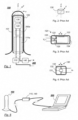
- Fig. 1 is a longitudinal schematic section of an apparatus 100 according to the invention.
- the apparatus is comprised of an elongate, cylindrical housing 101, which can be made of a relatively rigid plastic material.
- an outer casing 102 made of medical silicone can be provided on the outside of housing 101.
- the size of the housing is adapted for an opening in the pelvic floor.
- Housing 101 includes an oscillator 120 able to oscillate along one, two, or three axes, and an accelerometer 130 able to measure the acceleration along one, two, or three axes.
- oscillator 120 and accelerometer 130 are offset relative to each other along the longitudinal axis of the apparatus, i.e. the z-axis. Strictly speaking, therefore, they have separate axes in the x direction, e.g. x and x'. However, this has no significance as long as the axes are parallel to each other, cf. the previous section.
- the x-axes of the oscillator, accelerometer and apparatus are referred to as one axis, "the x-axis". The same applies for the y- and z-axes.
- Fig. 2 illustrates a triaxial accelerometer 130, having its axes x, y, and z parallel with the axes x, y, and z of the apparatus shown in Fig. 1 .
- the frequencies of the oscillations, and optionally also the amplitudes can be controlled independently of each other along said x, y, and z axes. This makes it possible to measure the strength of a muscle or muscle group running in parallel with the main axis of the apparatus, the z-axis, independently of muscles or muscle groups acting radially on the apparatus along a combination of the x- and y-axes of Fig. 1 .
- parameters of one, two, or three dimensions are denoted with boldfaced characters, and the component of a parameter along the x, y, and/or z axis is indexed with x, y, and z, respectively.
- the frequency ⁇ ( ⁇ x , ⁇ y , ⁇ z ).
- the three frequency components may have different values, and one or two of the components can be zero, i.e. one or two oscillators could be eliminated.
- a response or out signal a from accelerometer 130 calculated results ⁇ A, ⁇ , ⁇ , and so on.
- Components along the x, y, and z axes are measured and calculated independently of each other, e.g. as indicated in eqs. (1) to (4).
- the oscillator 120 can be controlled to vibrate with a specific frequency, preferably within the range of 15-120Hz, by a power supply 110.
- the oscillator 120 can be driven by a battery 111a, shown with broken lines in Fig. 1 .
- the output signal from accelerometer 130 can be passed to a signal processor 140 and thence to a computer 200 (see Figs. 5 and 6 ). Alternatively, the entire or parts of the signal and data processing can be performed by a unit 200a inside the housing 101.
- Oscillator 120, accelerometer 130, and signal processor 140 are commercially available products, and it is within the ability of a person skilled in the art to select models suited for the particular purpose. It is understood that Fig. 1 is a principle drawing, and that the connections between the components may include several channels, e.g. one input channel per oscillator axis and one output channel per accelerometer axis. In some applications, accelerometer 130 and/or signal processor 140 may be driven by electric power supplied through a USB connection, for example. In other applications, it may be necessary or convenient to have a separate grid-connected transformer 111 in the power supply 110, as shown in Fig. 6 .
- Fig. 3 illustrates the principle of a possible oscillator 120.
- the oscillator shown includes a permanent magnet 126 arranged in a coil 125.
- V x AC voltage
- V x AC voltage
- a current is driven through the coil
- a variable magnetic field is induced which drives the permanent magnet 126 back and forth in a reciprocating motion.
- the permanent magnet 126 is attached to a weight 122 which hence also moves back and forth.
- the oscillator is attached to housing 101, the apparatus 100 will oscillate along the x-axis.
- Fig. 4 illustrates the principle of a typical accelerometer.
- a piezoelectric disc or bar 133 is fixedly clamped within a housing 131.
- the disc 133 retains a seismic mass 132.
- an electric charge is produced, typically a few pC/g, on the disc 133 by the piezoelectric effect.
- the output signal is illustrated schematically as a x in Fig. 4 .
- Commercial vibrational testing accelerometers of this type typically have a frequency range from approx. 0.1 to above 4kHz, i.e. far outside the range of 15-120Hz preferred in the present invention.
- the present invention does not rely on any specific types of oscillators or accelerometers.
- eccentric weight oscillators may be used instead of the type shown schematically in fig. 3 .
- a design of the type shown in Fig. 3 can also be used as an accelerometer: In such a case, weight 122 is moved in dependency of the applied forces. This induces a movement of permanent magnet 126 inside coil 125, and a current is induced that can be read at the poles at V x .
- Fig. 5 illustrates a system in which a computer 200 controls an oscillator of apparatus 100 through a power supply 110.
- the computer 200 can be of any design. Suitable computers have a programmable processor, and include personal computers, portable units (PDAs), etc.
- Computer 200 can be connected to a display, printer, and/or data storage in a known manner for displaying and/or logging measurement results.
- Signals from an accelerometer (130, Fig. 1 ) of apparatus 100 are amplified and/or processed in a signal processor 140, and transferred to computer 200 for analysis and/or logging.
- the connection between apparatus 100 and the box 110, 140 may include several channels for controlling oscillators along several axes independently of each other as well as for measuring responses of a uniaxial or multiaxial accelerometer. The same applies for the connection between box 110, 140 and computer 200.
- This connection may be a USB (2.0 or the like) connection, and, in some applications, electric power may be supplied from the computer through the USB connection.
- signals may be transferred wirelessly (not shown), e.g. by way of radio signals, infrared light, or ultrasonic signals.
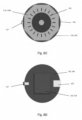
- Figs. 8A-8D show another embodiment of the system, and in particular a more detailed embodiment of signal processor 110, 140, according to the present invention, in which the power supply 110 and signal processor 140 can be embedded into a separate unit or box 110, 140 accommodating at least one rechargeable or replaceable battery or battery package 113 ( Fig. 8D ).
- EMG Electromyography
- the stand-alone unit or box 110, 140 can include a charge input. Additionally to the charge input, or in an alternative embodiment, in which the battery or batteries or the battery package 113 is to be replaced or charged at another location, the stand-alone unit or box 110, 140 may include a cover 114 which can be opened and closed, or the casing (housing) of the unit or one half of the unit or box 110 may be arranged so as to be easily opened and closed (i.e. without the need for using a tool).
- the wire 115 from apparatus 100 may be permanently connected 115A to the box 110 of signal processor 140, or, alternatively, may be arranged so as to be pluggable 115B (by means of a plug 115B) into the input port or connector 116 of the unit 110, 140.
- Signal processor 140 may further include a loudspeaker and/or display 118 for the instantaneous or immediate biofeedback on muscle activation as observed through the dampening of oscillations and/or force read from the apparatus 100 and/or EMG activity in the muscle acting on apparatus 100.
- Display 118 may have a suitable shape adapted for the requirements of functionality and placement.
- the unit 110, 140 may also include an on/off button 117.
- the electronic circuitry of signal processor 140 may be configured so as to switch off after a predetermined time interval of inactivity, e.g. from one to a few minutes of no active use.
- the stand-alone unit or box 110, 140 may include a CPU device and/or calibration means including at least one of a CPU device and various sensor means to allow, among other things, the calibration of a new apparatus 100 in the system.
- Unit 110, 140 may also transfer, e.g. wirelessly, real-time data to computer 200 of various reasons.
- Apparatus 100 may include an integrated triaxial gyro sensor which, together with the triaxial accelerometer 130, allows the data or signal processor 140 or computer 200 to calculate the 3D orientation of the apparatus 100.
- Fig. 6 is a schematic depiction of components of the system illustrated in Fig. 5 .
- a control module 230 determines an oscillator parameter, i.e. frequency and/or amplitude, for oscillator 120.
- the control module 230 could set the frequency ⁇ to a fixed initial value and then increase the frequency in predetermined increments ⁇ .
- control module 230 can use previous results for selecting other initial values and/or frequency intervals. This is described in more detail below. The same applies for the amplitude settings.
- controller 112 is connected to a power source in the form of a transformer 111 connected to the grid voltage V l delivering a power P with the desired current and voltage.
- the power source could be a battery 111a located inside the housing 101 of the apparatus.
- the controller 112 may control the amplitude A x and frequency ⁇ x of the oscillator by controlling the current, voltage, and frequency of the signal supplied at the poles V x of Fig 3 , and in a similar manner for oscillators oscillating along the y and/or z axes.
- the oscillation is imposed on tissue surrounding apparatus 100, and the response is measured by accelerometer 130.
- Signals from accelerometer 130 of apparatus 100 are passed to a signal processor 140, which is provided as a separate box including an array of accelerometers.
- Accelerometer 130 may include a preamplifier, and unit 140 may include a pre-amplifier. Other configurations are possible as well.
- the output signal from signal processor 140 is shown as a , and may represent, for example, acceleration along the x, y, and/or z axes at a measurement point at which the imposed oscillation was ⁇ i .
- a data capturing module 210 process the signal further, and may, for example, integrate an acceleration to obtain a velocity and once more to obtain a displacement, measure a phase difference, etc. Said integration of acceleration, measurement of phase difference, etc. may be carried out at several locations in the signal path using feedback operational amplifiers, firmware, and/or software , for example, in a known manner. Note that the signal path of Fig. 6 is exemplary only.
- Output data from the data capturing module 210 are shown schematically as a measurement point ⁇ , R, at which a result R is measured or calculated at an applied frequency ⁇ .
- the result R may represent one or more of: acceleration a , velocity, displacement, relative amplitude attenuation ⁇ A , phase shift, stress, strain, and/or dynamic modulus as discussed above.
- the oscillator amplitude may also be varied.
- the data capturing module can store a measurement sequence including a series of measurement points each representative of an oscillator parameter ⁇ or A and a measured or calculated result R .
- data values is understood to mean any parameter value and/or the components thereof along the x, y, and/or z axes.
- a data bus 205 carries data values between various components and modules of computer 200.
- a measurement series with a sequence of measurement points ( ⁇ i , R i ) can be temporarily be stored in a data storage 201 before the measurement series is further processed in an analysis module 220.
- the measurement points ( ⁇ i , R i ) could be passed to analysis module 220 at a later point, and the processing results, represented by ( ⁇ r , S ), could be stored in data storage 201 and/or displayed on a display means 202.
- Analysis module 220 is a module processing one or more measurement series to characterize the musculature and the development thereof using one or more parameters deemed suitable.
- a maximum response frequency ⁇ r is obtained for each measurement series.
- the maximum response frequency ⁇ r is the value of the imposed frequency for which the measurement parameter selected indicated a maximum response from the tissue surrounding the apparatus, such as the maximum amplitude attenuation, minimum amplitude measured, largest dynamic modulus, etc. This is discussed in more detail below.
- analysis module 220 may calculate any desired group value and/or carry out statistical analysis of the acquired data, such as statistical distributions, mean or expected value, variance, maximum values, and trends in the development of the measured and calculated results described above, for example.
- the group value S may represent a subinterval of the range of 15-120Hz within which the maximum response frequency ⁇ r is located with a given probability.
- This interval may be calculated as a confidence interval from earlier measurement series using known statistical methods, and is expected to become smaller as the number of measurement series increases and the variance hence reduces. The purpose of calculating such a subinterval is to avoid superfluous measurements.
- An exemplary trend analysis is the development of the maximum response frequency ⁇ r over a few days or weeks, which may provide information on training effect.
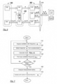
- Fig. 7 illustrates a method according to the invention.
- the musculature is imposed a first oscillation represented by ⁇ i .
- a first oscillation represented by ⁇ i .
- the oscillation may be imposed along one or more mutually orthogonal axes (x, y, z).
- the initial value could be about 15Hz, for example, along each axis.
- the apparatus has been used one or more times the initial values may be based on previous results and analyses.
- the response a i from the musculature is measured by means of an accelerometer 130 having axes oriented in parallel with the oscillator axes x, y, and/or z.
- Block 730 illustrates that a result R i is found from an imposed oscillation ⁇ i and its response a i as measured in a predetermined time interval.
- Results suitable for characterizing the musculature may be the relative amplitude attenuation ⁇ A , dynamic modulus ⁇ , and/or phase shift ⁇ between the applied and measured signals.
- the values may be measured and/or calculated as set out above in connection with eqs. (1) to (4), and independently of each other along the axis or axes x, y, and/or z.
- the measurement point ( ⁇ i , R i ) can be stored or logged as part of this step.
- an oscillation frequency for the next measurement point is calculated, and in determination block 750 a determination is made whether the measurement series has been completed.
- the loop ends in determination block 750 when the new frequency ⁇ i+1 exceeds a predetermined threshold, e.g. 120Hz, along the axis or axes.
- the objective is to find a maximum response using the smallest number of measurements possible.
- This may be carried out efficiently by way of a binary search.
- ⁇ 3 is selected as the center of the interval 50-120Hz in block 740, otherwise ⁇ 3 is selected as the center of the interval 15-50Hz in block 740. Similar bisection of the intervals is repeated in this alternative embodiment until determination block 750 indicates that the next interval is narrower than the desired resolution, e.g. 5Hz along each axis.
- determination block 750 indicates that the measurement series has not been completed, a new iteration is performed in which block 710 imposes an oscillation with a new frequency ⁇ i+1 , etc.
- determination block 750 indicates that the measurement series has been completed, the process proceeds to block 760.
- Block 770 has been drawn with dashed lines to illustrate that the method may, but does not necessarily, include controlling the oscillator to impose the practical value for the maximum response frequency while a user performs pelvic floor exercises as described in the introductory section.
- the resolution ⁇ should be selected so that the difference between the practical and actual values is of little or no significance. For example, if it turns out to be a telling difference between training with an imposed oscillation of 62Hz as compared to 60Hz, ⁇ in the above example should be reduced from 5Hz to 1Hz.
- the method may further include storing and/or displaying one or more oscillation parameters, measurement values, calculated results, and/or group values.
- Each data value may be stored in a data storage 201 and displayed on a monitor 202. It is also possible to log parameters by printing them on paper. Hence, a printer (not shown) may optionally be used instead of or in addition to data storage 201 and display 202 (e.g. a monitor) shown in fig. 6 .
- the method described above may further include analyzing the measured and calculated results using known statistical methods.
- the development of the maximum response frequency and/or other results over time may document the training effect.
- a confidence interval for ⁇ r can be estimated which is smaller than the entire measurement interval, e.g. 15-120Hz, but still large enough for the probability p that the maximum response frequency is located within said interval to be larger than a predetermined value, such as p > 95%.
- Data storage 201 may store several such measurement series recorded during a time period, e.g. one measurement series per day for 1-4 weeks, and/or only the particular frequency ⁇ r within each measurement series which resulted in, for example, the maximum amplitude attenuation or phase shift.
- calculating group value is intended to include any known types of statistic analysis, trend analysis as well as other forms of analysis performed on one or more measured or calculated results, stored, for example, as measurement series of measurement points ( ⁇ i , R i ) in data storage 201.
Landscapes
- Health & Medical Sciences (AREA)
- Physical Education & Sports Medicine (AREA)
- General Health & Medical Sciences (AREA)
- Life Sciences & Earth Sciences (AREA)
- Reproductive Health (AREA)
- Animal Behavior & Ethology (AREA)
- Veterinary Medicine (AREA)
- Public Health (AREA)
- Rehabilitation Therapy (AREA)
- Pain & Pain Management (AREA)
- Epidemiology (AREA)
- Gynecology & Obstetrics (AREA)
- Pathology (AREA)
- Surgery (AREA)
- Molecular Biology (AREA)
- Medical Informatics (AREA)
- Heart & Thoracic Surgery (AREA)
- Biomedical Technology (AREA)
- Engineering & Computer Science (AREA)
- Biophysics (AREA)
- Physics & Mathematics (AREA)
- Measurement Of The Respiration, Hearing Ability, Form, And Blood Characteristics Of Living Organisms (AREA)
- Rehabilitation Tools (AREA)
Description
- The present invention relates to an apparatus, system, and method for testing and exercising the pelvic floor musculature.
- The pelvic floor muscles are a mind-controlled and layered muscle group which surrounds the urethra, vagina, and rectum, and which, together with the sphincter muscles, functions to control these openings. This musculature also serves to support the urethra, bladder, and uterus, as well as to resist any increases in the abdominal pressure developed during physical exertion. The muscle group includes both longitudinal muscles and annular muscles.
- Training of the pelvic floor musculature has proven efficient in preventing and treating several conditions, e.g. incontinence. Numerous exercises exist for training the pelvic floor musculature. For a number of reasons, the effect of these exercises varies among people. Also, it is known that mechanical vibrations in a range below approx. 120 Hz applied to the tissue increase the training effect of such exercises. As the musculature becomes stronger, it will be possible to measure the training effect by measuring the ability of the musculature to retract.
- A stronger muscle can be expected to dampen an amplitude of oscillation applied thereto more than a weaker muscle. A first principle of measurement, therefore, may be to measure the amplitude dampening of an imposed oscillation. The measured amplitude can be described as A ~ A0sin(ωt). A relative amplitude dampening is defined as:

- A
- is the amplitude measured,
- A0
- is the amplitude imposed,
- ω
- is the angular frequency of the oscillation imposed, and
- t
- is time.
- It is considered well known to a person skilled in the art that the output signal from an accelerometer may represent an acceleration which can be integrated to obtain a velocity and a second time to obtain a displacement or deflection. It is also well known that accelerations, velocities, and displacements of equal magnitudes and opposite directions have average values of zero, and that meaningful parameters hence must be based on absolute values such as maximum acceleration, velocity, or amplitude, for example. In view of the above, it is clear that the dimensionless attenuation ΔA can be calculated from displacements in mm, velocities in m/s, accelerations in m/s2, and/or electrical signals input to the oscillator and output from the accelerometer. In any case, the attenuation ΔA can be expressed in dB, calibrated to display the force in Newton (N), etc. according to need and in manners known for persons skilled in the art.
- During exercise, the volume of the muscle cells increases and the skeleton of the cells becomes more rigid. In another model, therefore, the pelvic floor musculature can be regarded as a visco-elastic material, i.e. as a material having properties between a fully elastic material and an entirely rigid and inelastic (viscous) material. For example, a slack or weak muscle can be expected to exhibit relatively "elastic" properties, whereas a tight or strong muscle can be expected produce more resistance and thus relatively "viscous" properties. Formally:
- stress is the force acting to resist an imposed change divided by the area over which the force acts. Hence, stress is a pressure, and is measured in Pascal (Pa), and
- strain is the ratio between the change caused by the stress and the relaxed configuration of the object. Thus, strain is a dimensionless quantity.
- The modulus of elasticity is defined as the ratio λ = stress/strain. The dynamic modulus is the same ratio when the stress arises from an imposed oscillation. When an oscillation is imposed in a purely elastic material, the elongation measured is in phase with the imposed oscillation, i.e. strain occurs simultaneously with the imposed oscillation. When the oscillation is imposed in a purely viscous material, the strain lags the stress by 90° (π/2 radians). Visco-elastic materials behave as a combination of a purely elastic and a purely viscous material. Hence, the strain lags the imposed oscillation by a phase difference between 0 and π/2. The above can be expressed through the following equations:



- σ is stress from an imposed oscillation (Pa)
- ε is strain (dimensionless)
- ω is the oscillator frequency (Hz)
- t is time (s),
- ϕ is the phase difference varying between 0 (purely elastic) and π/2 (purely viscous), and
- λ is the dynamic module.
- Biomechanically, this may be interpreted as that a stronger muscle increases the force resisting the oscillation and thereby "delays" the vibrations measured by the accelerometer. This is equivalent with that a strong muscle is stiffer or "more viscous" than a slack, gelatinous, and "more elastic" muscle.
- A general problem in the prior art in the field is that measurement values are often given in terms of pressure, e.g. in millimeter water column. As pressure is a force divided by an area, the pressure reported will depend on the area of the measuring apparatus, and hence on the supplier. Therefore, in the literature in the field, measurement values are often given in the format '<Supplier_name> mmH20', for example. In turn, this results in that measurement values from different apparatuses are not directly comparable, and consequently a need exists for supplier independent measurement values in the field of the invention.
-
US 6,059,740 discloses an apparatus for testing and exercising pelvic floor musculature. The apparatus includes an elongate housing adapted for insertion into the pelvic floor aperture. The housing is divided longitudinally into two halves, and includes an oscillator as well as a cut out and equipment for measuring pressure applied to the housing halves from the pelvic floor musculature. The apparatus indicates the force pressing together the two halves in Newton (N), and essentially measures the training effect on muscles acting radially on the housing. -
GB 2 376 890 A claim 1 and a method for testing and exercising pelvic floor musculature with the features of the preamble of claim 11.US 2010/174218 A1 discloses a pelvic exercise system comprising accelerometers. - A need exists for an apparatus which also measures and trains the musculature running in parallel with a longitudinal direction of the apparatus or pelvic floor opening.
- The object of the present invention is to address one or more of the above Problems, while maintaining the advantages of prior art.
- The invention is defined by the apparatus of
claim 1, the system of claim 7 and the method of claim 11. Further developments of the invention are given in the dependent claims. - According to the present invention there is provided an apparatus for testing and exercising pelvic floor musculature, the apparatus comprising an elongate housing adapted for a pelvic floor opening and accommodating an oscillator, wherein the housing accommodates an accelerometer connected to a signal processor configured for communicating signals representative of values read from the accelerometer, wherein the x-axis of the accelerometer is arranged in parallel with the x-axis of the oscillator arranged for providing or imposing controlled oscillation(s) along the x-axis being perpendicular to the longitudinal or main, z-axis, of the apparatus on the pelvic floor musculature,wherein a data capturing module is provided which receives signals of the signal processor and calculates a relative amplitude attenuation, a phase delay and/or a dynamic modulus in one or more dimensions for characterizing the response from the pelvic floor musculature measured by the accelerometer.
- The use of an accelerometer for measuring a response makes it possible to use a closed housing, simplify the remaining construction, and increase the accuracy of the measurements. According to the present invention it is foreseen to calculate a relative amplitude attenuation, phase delay, and/or dynamic modulus in one or more dimensions. These parameters, combined or individually, are used for characterizing the musculature in a more accurately and detailed manner than is possible with the prior art.
- Also, imposing oscillations and/or measuring responses along several axes allow the adaptation of training and testing to specific muscle groups in the pelvis floor.
- Further, a system using such an apparatus with a controller configured for controlling the frequency and/or amplitude of the oscillation can be provided. The system is characterized in that it further includes a control module configured for determining an oscillator parameter within at least one time interval, and for providing the oscillator parameter to the controller; a data capturing module configured for receiving a response from the accelerometer and calculating a result as a function of the oscillator parameter and the received response; an analysis module configured for calculating at least one group value based on a series of measurements of oscillator parameters and the results thereof; a data storage configured for storing and retrieving at least one data value from a group consisting of the oscillator parameters, response, calculated result, and group value; and communication means configured for conveying the data value between the modules and the data storage.
- In a preferred embodiment, the musculature is imposed an oscillation of a frequency equal or close to the maximum response frequency during training of the musculature. The maximum response frequency is assumed to change over time, and may be, inter alia, displayed and/or logged in order to document training effect, alone or in combination with one or more other parameters.
- Additional features and embodiments will be apparent from the attached patent claims.
- The invention will be described in more detail in the detailed description below with reference to the appended drawings, in which:
-
Fig. 1 is a longitudinal schematic section of an apparatus; -
Fig. 2 illustrates alignment of a triaxial accelerometer in the apparatus ofFig. 1 ; -
Fig. 3 (prior art) shows the principle of an oscillator; -
Fig. 4 (prior art) shows the principle of an accelerometer; -
Fig. 5 is a schematic illustration of a system according to the invention; -
Fig. 6 is a schematic depiction of the functions of the system; -
Fig. 7 is a flow diagram illustrating a method according to the invention; and -
Figs. 8A-8D illustrate a more detailed embodiment of the signal processor according to the invention. -
Fig. 1 is a longitudinal schematic section of anapparatus 100 according to the invention. The apparatus is comprised of an elongate,cylindrical housing 101, which can be made of a relatively rigid plastic material. Advantageously, anouter casing 102 made of medical silicone can be provided on the outside ofhousing 101. The size of the housing is adapted for an opening in the pelvic floor. -
Housing 101 includes anoscillator 120 able to oscillate along one, two, or three axes, and anaccelerometer 130 able to measure the acceleration along one, two, or three axes. Preferably, the accelerometer axis or axes is/are aligned with the oscillator axis or axes, for the following reason:
Assume thatoscillator 120 effects an oscillation of the apparatus along an axis x, and that the response is measured along an axis x' forming an angle α with the x-axis. If a response along the x-axis is B, then the response along the x'-axis B' = B·cos α. B' has a maximum for cos α = 1, i.e. with α = 0 and the x'-axis parallel with the x-axis. Correspondingly, B' = 0 when the accelerometer axis is perpendicular to the oscillation (cos 90° = 0). Thus, by arranging the x-axis ofaccelerometer 130 in parallel with the x-axis ofoscillator 120 we expect the largest possible signal and hence the greatest sensitivity possible. The same is true along the y- and/or z-axes whenapparatus 100 has more than one axis. Also, the level of crosstalk between the measured signals is minimized when the axes are perpendicular to each other, e.g. as shown with the x, y, z coordinate system ofFig. 1 . - From
Fig. 1 is can also be seen thatoscillator 120 andaccelerometer 130 are offset relative to each other along the longitudinal axis of the apparatus, i.e. the z-axis. Strictly speaking, therefore, they have separate axes in the x direction, e.g. x and x'. However, this has no significance as long as the axes are parallel to each other, cf. the previous section. Hence, for convenience, the x-axes of the oscillator, accelerometer and apparatus are referred to as one axis, "the x-axis". The same applies for the y- and z-axes. -
Fig. 2 illustrates atriaxial accelerometer 130, having its axes x, y, and z parallel with the axes x, y, and z of the apparatus shown inFig. 1 . In a preferred embodiment, the frequencies of the oscillations, and optionally also the amplitudes, can be controlled independently of each other along said x, y, and z axes. This makes it possible to measure the strength of a muscle or muscle group running in parallel with the main axis of the apparatus, the z-axis, independently of muscles or muscle groups acting radially on the apparatus along a combination of the x- and y-axes ofFig. 1 . - In the following, parameters of one, two, or three dimensions are denoted with boldfaced characters, and the component of a parameter along the x, y, and/or z axis is indexed with x, y, and z, respectively. For example, the frequency ω = (ωx, ωy, ωz). In some embodiments, the three frequency components may have different values, and one or two of the components can be zero, i.e. one or two oscillators could be eliminated. The same applies for a response or out signal a from
accelerometer 130, calculated results ΔA, ϕ, λ, and so on. Components along the x, y, and z axes are measured and calculated independently of each other, e.g. as indicated in eqs. (1) to (4). - The
oscillator 120 can be controlled to vibrate with a specific frequency, preferably within the range of 15-120Hz, by apower supply 110. Alternatively, theoscillator 120 can be driven by abattery 111a, shown with broken lines inFig. 1 . - The output signal from
accelerometer 130 can be passed to asignal processor 140 and thence to a computer 200 (seeFigs. 5 and6 ). Alternatively, the entire or parts of the signal and data processing can be performed by aunit 200a inside thehousing 101. -
Oscillator 120,accelerometer 130, andsignal processor 140 are commercially available products, and it is within the ability of a person skilled in the art to select models suited for the particular purpose. It is understood thatFig. 1 is a principle drawing, and that the connections between the components may include several channels, e.g. one input channel per oscillator axis and one output channel per accelerometer axis. In some applications,accelerometer 130 and/orsignal processor 140 may be driven by electric power supplied through a USB connection, for example. In other applications, it may be necessary or convenient to have a separate grid-connectedtransformer 111 in thepower supply 110, as shown inFig. 6 . -
Fig. 3 illustrates the principle of apossible oscillator 120. The oscillator shown includes apermanent magnet 126 arranged in acoil 125. When an AC voltage Vx is applied to the poles and a current is driven through the coil, a variable magnetic field is induced which drives thepermanent magnet 126 back and forth in a reciprocating motion. Thepermanent magnet 126 is attached to aweight 122 which hence also moves back and forth. When the oscillator is attached tohousing 101, theapparatus 100 will oscillate along the x-axis. -
Fig. 4 illustrates the principle of a typical accelerometer. A piezoelectric disc or bar 133 is fixedly clamped within ahousing 131. Thedisc 133 retains aseismic mass 132. When the housing is moved back and forth along the x-axis, the disc will be acted on by themass 132 and an electric charge is produced, typically a few pC/g, on thedisc 133 by the piezoelectric effect. For frequencies below about one third of the resonance frequency of the accelerometer housing, this charge will be proportional with the acceleration. The output signal is illustrated schematically as ax inFig. 4 . Commercial vibrational testing accelerometers of this type typically have a frequency range from approx. 0.1 to above 4kHz, i.e. far outside the range of 15-120Hz preferred in the present invention. - The present invention does not rely on any specific types of oscillators or accelerometers. For example, eccentric weight oscillators may be used instead of the type shown schematically in
fig. 3 . A design of the type shown inFig. 3 can also be used as an accelerometer: In such a case,weight 122 is moved in dependency of the applied forces. This induces a movement ofpermanent magnet 126 insidecoil 125, and a current is induced that can be read at the poles at Vx. -
Fig. 5 illustrates a system in which acomputer 200 controls an oscillator ofapparatus 100 through apower supply 110. Thecomputer 200 can be of any design. Suitable computers have a programmable processor, and include personal computers, portable units (PDAs), etc.Computer 200 can be connected to a display, printer, and/or data storage in a known manner for displaying and/or logging measurement results. - Signals from an accelerometer (130,
Fig. 1 ) ofapparatus 100 are amplified and/or processed in asignal processor 140, and transferred tocomputer 200 for analysis and/or logging. The connection betweenapparatus 100 and thebox box computer 200. This connection may be a USB (2.0 or the like) connection, and, in some applications, electric power may be supplied from the computer through the USB connection. - In some embodiments, signals may be transferred wirelessly (not shown), e.g. by way of radio signals, infrared light, or ultrasonic signals.
-
Figs. 8A-8D show another embodiment of the system, and in particular a more detailed embodiment ofsignal processor power supply 110 andsignal processor 140 can be embedded into a separate unit orbox Fig. 8D ). -
Signal processor 140 may also include: a CPU including the appropriate software; electronic circuitry programmed with suitable algorithms for managing and controlling the oscillation frequency and optionally the oscillation amplitude; input(s) for at least one EMG sensor (EMG = Electromyography); and input(s) for at least one force sensor. - The stand-alone unit or
box box box 110 may be arranged so as to be easily opened and closed (i.e. without the need for using a tool). - The
wire 115 fromapparatus 100 may be permanently connected 115A to thebox 110 ofsignal processor 140, or, alternatively, may be arranged so as to be pluggable 115B (by means of aplug 115B) into the input port orconnector 116 of theunit -
Signal processor 140 may further include a loudspeaker and/or display 118 for the instantaneous or immediate biofeedback on muscle activation as observed through the dampening of oscillations and/or force read from theapparatus 100 and/or EMG activity in the muscle acting onapparatus 100. Display 118 may have a suitable shape adapted for the requirements of functionality and placement. An octagonal (eight-sided) 118B, six-sided or round 118A LCD or LED display 118, having about 40segments 119, for example, could be used. Theunit button 117. In addition, or alternatively, the electronic circuitry ofsignal processor 140 may be configured so as to switch off after a predetermined time interval of inactivity, e.g. from one to a few minutes of no active use. - Additionally, the stand-alone unit or
box new apparatus 100 in the system.Unit computer 200 of various reasons. -
Apparatus 100 may include an integrated triaxial gyro sensor which, together with thetriaxial accelerometer 130, allows the data orsignal processor 140 orcomputer 200 to calculate the 3D orientation of theapparatus 100. -
Fig. 6 is a schematic depiction of components of the system illustrated inFig. 5 . - A
control module 230, e.g. hardware and software in thecomputer 200, determines an oscillator parameter, i.e. frequency and/or amplitude, foroscillator 120. When the apparatus is being used for the first time, thecontrol module 230 could set the frequency ω to a fixed initial value and then increase the frequency in predetermined increments Δω. On subsequent use,control module 230 can use previous results for selecting other initial values and/or frequency intervals. This is described in more detail below. The same applies for the amplitude settings. Alternatively, oscillator parameters could be determined in a binary search which is ended when the values of two consecutively calculated values are closer than a predetermined resolution, e.g. Δωx = 5Hz. - Both frequency and amplitude may be adjusted along the x, y, and z axes independently of each other by means of
controller 112. InFig. 6 ,controller 112 is connected to a power source in the form of atransformer 111 connected to the grid voltage Vl delivering a power P with the desired current and voltage. As shown inFig. 1 , in the alternative, the power source could be abattery 111a located inside thehousing 101 of the apparatus. For example, thecontroller 112 may control the amplitude Ax and frequency ωx of the oscillator by controlling the current, voltage, and frequency of the signal supplied at the poles Vx ofFig 3 , and in a similar manner for oscillators oscillating along the y and/or z axes. - The oscillation is imposed on
tissue surrounding apparatus 100, and the response is measured byaccelerometer 130. - Signals from
accelerometer 130 ofapparatus 100 are passed to asignal processor 140, which is provided as a separate box including an array of accelerometers.Accelerometer 130 may include a preamplifier, andunit 140 may include a pre-amplifier. Other configurations are possible as well. The output signal fromsignal processor 140 is shown as a, and may represent, for example, acceleration along the x, y, and/or z axes at a measurement point at which the imposed oscillation was ωi . - A
data capturing module 210 process the signal further, and may, for example, integrate an acceleration to obtain a velocity and once more to obtain a displacement, measure a phase difference, etc. Said integration of acceleration, measurement of phase difference, etc. may be carried out at several locations in the signal path using feedback operational amplifiers, firmware, and/or software , for example, in a known manner. Note that the signal path ofFig. 6 is exemplary only. - Output data from the
data capturing module 210 are shown schematically as a measurement point ω, R, at which a result R is measured or calculated at an applied frequency ω . The result R may represent one or more of: acceleration a, velocity, displacement, relative amplitude attenuation ΔA, phase shift, stress, strain, and/or dynamic modulus as discussed above. In some applications, the oscillator amplitude may also be varied. Advantageously, the data capturing module can store a measurement sequence including a series of measurement points each representative of an oscillator parameter ω or A and a measured or calculated result R . As used herein and in the claims, the term "data values" is understood to mean any parameter value and/or the components thereof along the x, y, and/or z axes. - A
data bus 205 carries data values between various components and modules ofcomputer 200. For example, a measurement series with a sequence of measurement points ( ωi , Ri ) can be temporarily be stored in adata storage 201 before the measurement series is further processed in ananalysis module 220. In another embodiment, the measurement points ( ωi , Ri ) could be passed toanalysis module 220 at a later point, and the processing results, represented by ( ωr , S), could be stored indata storage 201 and/or displayed on a display means 202. -
Analysis module 220 is a module processing one or more measurement series to characterize the musculature and the development thereof using one or more parameters deemed suitable. - In a preferred embodiment, a maximum response frequency ωr is obtained for each measurement series. The maximum response frequency ωr is the value of the imposed frequency for which the measurement parameter selected indicated a maximum response from the tissue surrounding the apparatus, such as the maximum amplitude attenuation, minimum amplitude measured, largest dynamic modulus, etc. This is discussed in more detail below.
- In principle,
analysis module 220 may calculate any desired group value and/or carry out statistical analysis of the acquired data, such as statistical distributions, mean or expected value, variance, maximum values, and trends in the development of the measured and calculated results described above, for example. - In one embodiment, for example, the group value S may represent a subinterval of the range of 15-120Hz within which the maximum response frequency ωr is located with a given probability. This interval may be calculated as a confidence interval from earlier measurement series using known statistical methods, and is expected to become smaller as the number of measurement series increases and the variance hence reduces. The purpose of calculating such a subinterval is to avoid superfluous measurements.
- An exemplary trend analysis is the development of the maximum response frequency ωr over a few days or weeks, which may provide information on training effect.
-
Fig. 7 illustrates a method according to the invention. - In
block 710, the musculature is imposed a first oscillation represented by ωi . In practice, this can be accomplished by introducing an apparatus as described above into a pelvic floor aperture and supply theoscillator 120 with electric power. The oscillation may be imposed along one or more mutually orthogonal axes (x, y, z). At the first use, the initial value could be about 15Hz, for example, along each axis. After the apparatus has been used one or more times the initial values may be based on previous results and analyses. - In
block 720, the response ai from the musculature is measured by means of anaccelerometer 130 having axes oriented in parallel with the oscillator axes x, y, and/or z. -
Block 730 illustrates that a result Ri is found from an imposed oscillation ωi and its response ai as measured in a predetermined time interval. The measurement point ( ωi , Ri ) may be part of a measurement series in which i = 1, 2, ... n, and each index i represents a separate time interval. Both the imposed frequency and the measured or calculated result have distinct values along the oscillator axes. Results suitable for characterizing the musculature may be the relative amplitude attenuation ΔA , dynamic modulus λ , and/or phase shift ϕ between the applied and measured signals. The values may be measured and/or calculated as set out above in connection with eqs. (1) to (4), and independently of each other along the axis or axes x, y, and/or z. The measurement point ( ωi , Ri ) can be stored or logged as part of this step. - In
block 740 an oscillation frequency for the next measurement point is calculated, and in determination block 750 a determination is made whether the measurement series has been completed. - In a first embodiment of the method, the imposed frequency is incrementally increased in
block 740, for example according to ωi = ω0 + i·Δω, where Δω denotes a desired resolution for the measurement series, such as 1Hz or 5Hz. In this case, the loop ends indetermination block 750 when the new frequency ωi+1 exceeds a predetermined threshold, e.g. 120Hz, along the axis or axes. - In an alternative embodiment of the method, the objective is to find a maximum response using the smallest number of measurements possible. This may be carried out efficiently by way of a binary search. For example, assume that the result R from
block 730 increases with the response of the musculature to the imposed oscillations, that a first interval is 15Hz to 120Hz, and that the desired resolution is 5Hz along each axis. In this case, the binary search can be performed by bisecting the interval, rounding the frequency down to the nearest integer frequency divisible with the resolution, and compare the results ofblock 730 for each of the two frequencies in the upper and lower parts of the interval, e.g. R1 at ω1 = 15Hz and R2 at ω2 = 50Hz. If R2 > R1, ω3 is selected as the center of the interval 50-120Hz inblock 740, otherwise ω3 is selected as the center of the interval 15-50Hz inblock 740. Similar bisection of the intervals is repeated in this alternative embodiment untildetermination block 750 indicates that the next interval is narrower than the desired resolution, e.g. 5Hz along each axis. - If the responses along the axes are independent of each other, a binary search in the interval 15-120Hz with a resolution of 5Hz along each axis will be able to find an approximate maximum response frequency using at most 6 measurement points, whereas a sequential search in the interval 15-120Hz with a resolution of 5Hz would require 21 measurement points.
- If
determination block 750 indicates that the measurement series has not been completed, a new iteration is performed in which block 710 imposes an oscillation with a new frequency ωi+1 , etc. Whendetermination block 750 indicates that the measurement series has been completed, the process proceeds to block 760. - In
block 760 one or more measurement series is analyzed as described foranalysis module 220 above. In a preferred embodiment, the maximum response frequency ωr is calculated for each measurement series. By definition, this is the frequency at which the musculature responds most strongly to the imposed oscillation. In practice, the maximum response frequency can be rounded down to the nearest integer frequency which is divisible with the resolution, i.e.
- ωr is the practical value of the maximum response frequency,
- ωr' is the theoretical or ideal value of the maximum response frequency,
- Δω· is the resolution chosen, e.g. 5Hz as in the above example, and round() is a function which rounds down to the nearest integer.
-
Block 770 has been drawn with dashed lines to illustrate that the method may, but does not necessarily, include controlling the oscillator to impose the practical value for the maximum response frequency while a user performs pelvic floor exercises as described in the introductory section. Hence, in a preferred embodiment, the resolution Δω should be selected so that the difference between the practical and actual values is of little or no significance. For example, if it turns out to be a telling difference between training with an imposed oscillation of 62Hz as compared to 60Hz, Δω in the above example should be reduced from 5Hz to 1Hz. - The method may further include storing and/or displaying one or more oscillation parameters, measurement values, calculated results, and/or group values. Each data value may be stored in a
data storage 201 and displayed on amonitor 202. It is also possible to log parameters by printing them on paper. Hence, a printer (not shown) may optionally be used instead of or in addition todata storage 201 and display 202 (e.g. a monitor) shown infig. 6 . - The method described above may further include analyzing the measured and calculated results using known statistical methods. In one embodiment, the development of the maximum response frequency and/or other results over time, for example, may document the training effect. Also, in the present or other applications, a confidence interval for ωr can be estimated which is smaller than the entire measurement interval, e.g. 15-120Hz, but still large enough for the probability p that the maximum response frequency is located within said interval to be larger than a predetermined value, such as p > 95%.
- This may reduce the number of measurement points in the next measurement series, which may be recorded one or a few days later, for example, and stored in data storage 201 (
Fig. 6 ).Data storage 201 may store several such measurement series recorded during a time period, e.g. one measurement series per day for 1-4 weeks, and/or only the particular frequency ω r within each measurement series which resulted in, for example, the maximum amplitude attenuation or phase shift. - Naturally, statistical analysis, trend analysis, etc. may be performed on one or more measured or calculated results, not only on the frequency as described above. The expression "calculating group value", as used in the patent claims, is intended to include any known types of statistic analysis, trend analysis as well as other forms of analysis performed on one or more measured or calculated results, stored, for example, as measurement series of measurement points ( ωi , Ri ) in
data storage 201.
Claims (19)
- An apparatus (100) for testing and exercising pelvic floor musculature, the apparatus comprising an elongate housing (101) adapted for a pelvic floor opening and accommodating an oscillator (120), wherein the housing (101) accommodates an accelerometer (130) able to measure the acceleration along at least the x-axis, and wherein the apparatus (100) further comprises a signal processor (140) connected to the accelerometer and configured for communicating signals representative of values read from the accelerometer (130), wherein the x-axis of the accelerometer (130) is arranged in parallel with the x-axis of the oscillator (120) arranged for providing or imposing controlled oscillation(s) along the x-axis being perpendicular to the longitudinal or main, z-axis, of the apparatus (100) on the pelvic floor musculature,
wherein a data capturing module (210) is provided which receives signals of the signal processor (140) and calculates a relative amplitude attenuation, a phase delay and/or a dynamic modulus in one or more dimensions for characterizing the response from the pelvic floor musculature measured by the accelerometer (130). - The apparatus of claim 1, wherein the oscillator (120) oscillates along more than one oscillator axes (x, y, z) being perpendicular to each other.
- The apparatus of claim 2, wherein the accelerometer (130) measures response along measurement axes being parallel with the oscillator axes.
- The apparatus of claim 2 or 3, wherein a controller (112) adjusts the amplitude (A) and/or frequency ( ω ) of the oscillator (120) along each of the oscillator axes independently of oscillations along the other oscillator axes.
- The apparatus of any one of claims 1-4, wherein the oscillator (120) is configured for oscillating with a frequency ( ω ) in the range of 15 to 120 Hz along each of the oscillator axes.
- The apparatus of any one of claims 1-5, wherein the housing (101) is coated with medical silicone (102).
- A system for testing and exercising pelvic floor musculature,
wherein the system comprises:- an apparatus (100) comprising an oscillator (120) and an accelerometer (130) connected to a signal processor (140) and being in accordance with any one of claims 1-6,- a control module (230) configured for determining an oscillator parameter ( ω , A ) within at least one time interval, and for providing the oscillator parameter to a controller (112) configured for controlling the frequency and/or amplitude of the oscillation imposed by the oscillator (120);- said data capturing module (210) configured for receiving a response ( a ) from the accelerometer (130) and calculating a result ( R ) as a function of the oscillator parameter and the received response, wherein the result ( R ) is selected from a group consisting of: relative amplitude attenuation ( ΔA ), dynamic modulus ( λ ), and phase delay ( ϕ ) between the applied oscillation(s) and the measured response by the accelerometer (130);- an analysis module (220) configured for calculating at least one group value ( ωR1 , S ) based on a measurement series of oscillator parameters and the results thereof,- a data storage (201) configured for storing and retrieving at least one data value from a group consisting of: the oscillator parameters ( ω , A), response ( a ), calculated result ( R ), and group value ( ωR1 , S ), and- communication means (205) configured for conveying the data value between the modules (210, 220,230) and the data storage (201). - The system of claim 7, wherein at least one of: an electric power source (111a), controller (112), signal processor (140), data capturing module (210), analysis module (220), control module (230), data storage (201), and communication means (205) is disposed within the housing (101) of the apparatus.
- The system of claim 7 or 8, further comprising display means (202) configured for displaying at least one data value.
- The system of any one of claims 7-9, wherein the group value (ω R1 , S ) from the analysis module (220) is selected from a group consisting of: a maximum response frequency ( ωR ) and a subinterval of the frequency range of 15 to 120 Hz.
- A method for testing and exercising pelvic floor musculature,comprising the step of imposing, with the help of an oscillator (120), a controlled oscillation on the musculature along the x-axis of an apparatus (100) for testing and exercising the pelvic floor musculature, said x-axis being perpendicular to the longitudinal or main z-axis thereof,further comprising the steps of:- measuring the response from the musculature using an accelerometer (130) able to measure the acceleration along at least the x-axis, wherein the x-axis of the accelerometer (130) is being arranged in parallel with the x-axis of the oscillator (120),- characterizing, with the help of a signal processor (140), the musculature based on the response to the oscillation imposed, andwherein for characterizing the response from the pelvic floor musculature a relative amplitude attenuation, a phase delay and/or a dynamic modulus in one or more dimensions are/is calculated.
- The method of claim 11, wherein the oscillation is imposed along more than one oscillator axes (x, y, z) being perpendicular to each other.
- The method of claim 12, wherein the accelerometer (130) measures response along measurement axes being parallel with said oscillator axes.
- The method of claim 12 or 13, wherein the amplitude ( A ) and/or frequency ( ω ) of the oscillation is adjusted along each of said oscillator axes independently of the oscillation along the other oscillator axes.
- The method of any of claims 11-14, wherein the oscillation is imposed with a frequency ( ω ) in the range of 15 to 120 Hz along each of said oscillator axes.
- The method of claim 14 or 15, further comprising the steps of:a) determining an oscillator parameter ( ω , A ) in at least one time interval;b) effecting an oscillation using the oscillator parameter in the time interval;c) obtaining a result ( R ) as a function of the oscillator parameter and the measured response;d) repeating steps a) to c) in a measurement series with several discrete time intervals; ande) calculating at least one group value ( ωR1 , S ) based on the measurement series of the oscillator parameters and the results thereof.
- The method of claim 16, further comprising the step of imposing an oscillation of a frequency near a maximum response frequency ( ωr ), for which the result indicates that the response is greatest, during training of the pelvic floor musculature.
- The method of claim 16 or 17, further comprising the step of storing and/or displaying group values for a number of measurement series.
- The method of any one of claims 16-18, further comprising the step of using at least one stored frequency value for estimating a subinterval within the frequency range of 15 to 120 Hz, within which interval a result or group value is expected to fall with a predetermined probability.
Applications Claiming Priority (2)
| Application Number | Priority Date | Filing Date | Title |
|---|---|---|---|
| NO20110524A NO333208B1 (en) | 2011-04-05 | 2011-04-05 | Apparatus and system for testing and training pelvic floor muscles |
| PCT/NO2012/050058 WO2012138232A1 (en) | 2011-04-05 | 2012-04-03 | Device, system and method for testing and training of pelvic floor musculature |
Publications (4)
| Publication Number | Publication Date |
|---|---|
| EP2693946A1 EP2693946A1 (en) | 2014-02-12 |
| EP2693946A4 EP2693946A4 (en) | 2015-03-04 |
| EP2693946B1 true EP2693946B1 (en) | 2023-10-25 |
| EP2693946C0 EP2693946C0 (en) | 2023-10-25 |
Family
ID=46969414
Family Applications (1)
| Application Number | Title | Priority Date | Filing Date |
|---|---|---|---|
| EP12767978.5A Active EP2693946B1 (en) | 2011-04-05 | 2012-04-03 | Device, system and method for testing and training of pelvic floor musculature |
Country Status (5)
| Country | Link |
|---|---|
| US (4) | US9949888B2 (en) |
| EP (1) | EP2693946B1 (en) |
| CN (1) | CN103702610B (en) |
| NO (1) | NO333208B1 (en) |
| WO (1) | WO2012138232A1 (en) |
Families Citing this family (41)
| Publication number | Priority date | Publication date | Assignee | Title |
|---|---|---|---|---|
| NO333208B1 (en) | 2011-04-05 | 2013-04-08 | Pelvital As | Apparatus and system for testing and training pelvic floor muscles |
| US11166661B2 (en) | 2011-04-19 | 2021-11-09 | Analytica Limited | Intra vaginal device to aid in training and determining muscle strength |
| US20150112230A1 (en) | 2011-11-28 | 2015-04-23 | Remendium Labs Llc | Treatment of male urinary incontinence and sexual dysfunction |
| US20150112231A1 (en) | 2011-11-28 | 2015-04-23 | Remendium Labs Llc | Treatment of fecal incontinence |
| US10470862B2 (en) | 2012-01-30 | 2019-11-12 | Remendium Labs Llc | Treatment of pelvic organ prolapse |
| US9776040B2 (en) | 2012-11-30 | 2017-10-03 | LELO Inc. | Exercising kegel muscles using preprogrammed exercise programs |
| US9439830B2 (en) * | 2013-01-22 | 2016-09-13 | Bryan Joseph NORTON | Transverse-mode-resonant stimulation device |
| CA2936061A1 (en) * | 2014-01-06 | 2015-07-09 | Remendium Labs Llc | System and method for kegel training |
| US11324999B2 (en) | 2014-01-13 | 2022-05-10 | Skye Health, Inc. | Methods and devices for sensing, guiding, and/or tracking pelvic exercise |
| US9993688B2 (en) * | 2014-01-13 | 2018-06-12 | Skye Health, Inc. | Device and method for sensing, guiding, and/or tracking pelvic exercise |
| EP2995292A3 (en) | 2014-09-13 | 2016-07-06 | Standard Innovation SARL | Sexual wellness device |
| GB2531744B (en) * | 2014-10-28 | 2017-11-22 | Chiaro Tech Ltd | Method and apparatus for monitoring the pelvic floor muscles |
| AU2015380288B2 (en) * | 2015-01-29 | 2020-09-24 | Stratos MedTech Holdings Pty Ltd | An intra vaginal device to aid in training and determining muscle strength |
| BR102015005444A2 (en) * | 2015-03-11 | 2016-09-13 | Mirca Christina Da Silva Batista | wireless electromyograph equipment and its operating system |
| HK1249385A1 (en) * | 2015-03-24 | 2018-11-02 | 卡利卡股份有限公司 | Kegel health system |
| WO2016170194A1 (en) * | 2015-04-20 | 2016-10-27 | Logic Activity 2000 S. L. | Device and method for sports training, rehabilitation, entertainment, and monitoring and supervision of physical exercise |
| CN105212926A (en) * | 2015-10-20 | 2016-01-06 | 王军 | Training aids at the bottom of intelligent radio biofeedback monitor and basin |
| AU2016384215A1 (en) * | 2015-12-28 | 2018-07-19 | Novipel Holding Aps | A pelvic floor muscle training and profiling apparatus for inserting into a body cavity of a human and a method for visualizing pelvic floor muscle contractions |
| CN105962957A (en) * | 2016-05-18 | 2016-09-28 | 深圳大学 | System for evaluating female pelvic floor muscle strength |
| KR102589133B1 (en) * | 2016-07-29 | 2023-10-12 | 레노비아 인크. | Devices, systems, and methods for training pelvic floor muscles |
| CN108871636A (en) * | 2017-05-09 | 2018-11-23 | 北京华信诚达科技有限公司 | A kind of gynaecology's basin bottom medical data acquisition terminal |
| EP4628016A3 (en) * | 2017-10-27 | 2025-12-17 | Axena Health, Inc. | Devices, systems, and methods for training pelvic floor muscles |
| WO2019118561A1 (en) * | 2017-12-13 | 2019-06-20 | Pelvital Usa, Inc. | Apparatus, system, and method for tissue regeneration |
| US12138019B2 (en) | 2018-04-13 | 2024-11-12 | Axena Health, Inc. | Devices, systems, and methods for training pelvic floor muscles |
| WO2019210204A1 (en) | 2018-04-27 | 2019-10-31 | Renovia Inc. | Devices, systems, and methods for treating urinary and fecal incontinence |
| JP2022506203A (en) | 2018-10-30 | 2022-01-17 | レノビア インコーポレイテッド | Devices, systems, and methods for monitoring bladder function |
| CN109568897B (en) * | 2018-11-03 | 2021-06-11 | 厦门波耐模型设计有限责任公司 | Pelvic floor muscle function training device and system |
| US11571357B2 (en) * | 2019-01-29 | 2023-02-07 | Joylux, Inc. | Vaginal health diagnostics |
| AU2020217000B2 (en) * | 2019-02-01 | 2025-08-21 | Luke DERY | Adjustable apparatus, system, and method for cellular restructuring |
| USD888948S1 (en) | 2019-04-02 | 2020-06-30 | Renovia Inc. | Intravaginal device |
| USD898911S1 (en) | 2019-04-03 | 2020-10-13 | Renovia Inc. | Intravaginal device assembly |
| USD889649S1 (en) | 2019-04-05 | 2020-07-07 | Renovia Inc. | Intravaginal device |
| USD896958S1 (en) | 2019-04-11 | 2020-09-22 | Renovia Inc. | Intravaginal device |
| USD899593S1 (en) | 2019-04-12 | 2020-10-20 | Renovia Inc. | Intravaginal device |
| USD896959S1 (en) | 2019-04-23 | 2020-09-22 | Renovia Inc. | Intravaginal device |
| USD897530S1 (en) | 2019-04-23 | 2020-09-29 | Renovia Inc. | Intravaginal device |
| USD922575S1 (en) | 2019-10-25 | 2021-06-15 | Renovia Inc. | Intravaginal device |
| MY209250A (en) * | 2020-09-01 | 2025-06-30 | Bioinfinity M Sdn Bhd | Adjustable perineometer device |
| US20220323295A1 (en) * | 2021-04-09 | 2022-10-13 | Abraham Morgentaler | Method of Treating Urinary Dysfunction |
| TWM623768U (en) * | 2021-11-10 | 2022-02-21 | 守婦者生醫科技股份有限公司 | Pelvic floor muscle activity sound detection device |
| CN114307085A (en) * | 2022-02-09 | 2022-04-12 | 北京惠仁阳光医疗器械有限公司 | Resistance training device for pelvic floor rehabilitation |
Family Cites Families (49)
| Publication number | Priority date | Publication date | Assignee | Title |
|---|---|---|---|---|
| AT402366B (en) * | 1992-03-09 | 1997-04-25 | Michl Ilse Dr | DEVICE FOR MONITORING THE CONTRACABILITY OF THE PELVIC MUSCULAR |
| JP3151153B2 (en) * | 1995-09-20 | 2001-04-03 | 定夫 尾股 | Frequency deviation detection circuit and measuring instrument using the same |
| US6110099A (en) | 1995-11-13 | 2000-08-29 | Benderev; Theodore V. | Devices and methods for assessment and treatment of urinary and fecal incontinence |
| US5782745A (en) | 1995-11-13 | 1998-07-21 | Benderev; Theodore V. | Devices and methods for assessment and treatment of urinary and fecal incontinence |
| EP0829226B1 (en) * | 1996-03-22 | 2004-10-27 | Seiko Epson Corporation | Exercise quantity measuring device |
| NO982134L (en) | 1998-05-11 | 1999-11-12 | Gunnar Leivseth | Method for diagnosis and testing / training of pelvic floor muscles |
| US6964643B2 (en) | 1998-11-18 | 2005-11-15 | Nugyn, Inc. | Devices and methods for treatment of incontinence |
| WO2000047108A1 (en) | 1999-02-08 | 2000-08-17 | Medoc Ltd. | Ambulatory monitor |
| US6063044A (en) * | 1999-04-20 | 2000-05-16 | Leonard; Charles T. | Apparatus for measuring muscle tone |
| US7104950B2 (en) | 1999-07-02 | 2006-09-12 | Th, Inc. | Sexual stimulation |
| RU2264787C2 (en) * | 1999-11-24 | 2005-11-27 | Инновэйтив Девелопмент Энд Маркетинг Ас | Method and device for training pelvic fundus muscles |
| CN1216572C (en) * | 1999-11-24 | 2005-08-31 | 创新发展销售有限公司 | Method and apparatus for training pelvic floor muscles |
| US6406411B1 (en) * | 1999-12-13 | 2002-06-18 | Peter A. Guagliano | Pelvic floor exercise device |
| US6244066B1 (en) | 2000-05-01 | 2001-06-12 | Larose Aaron J. | Floating cooler |
| JP2001334000A (en) | 2000-05-30 | 2001-12-04 | Tanita Corp | Urinary incontinence training support device |
| GB2376890B (en) | 2001-06-27 | 2004-11-10 | Andrew Timothy Sweeney | Massage device |
| JP4052504B2 (en) * | 2002-01-29 | 2008-02-27 | 学校法人日本大学 | Apparatus for measuring elasticity characteristics of living tissue |
| KR100466706B1 (en) | 2002-05-20 | 2005-01-17 | 모승기 | Cone for Exercising Pelvic Floor Muscle And Nerve |
| US20090312817A1 (en) | 2003-11-26 | 2009-12-17 | Wicab, Inc. | Systems and methods for altering brain and body functions and for treating conditions and diseases of the same |
| NL1025526C2 (en) * | 2004-02-19 | 2005-08-22 | Msys Ag | Training device for pelvic floor. |
| US7641688B2 (en) | 2004-09-16 | 2010-01-05 | Evera Medical, Inc. | Tissue augmentation device |
| DE202004019194U1 (en) * | 2004-12-06 | 2006-04-13 | Storz Medical Ag | Pelvictrainer |
| US7214204B2 (en) | 2004-12-16 | 2007-05-08 | Nanma Manufacturing Co. Ltd. | Vibrating massager with visual communication means |
| KR100710908B1 (en) | 2005-07-19 | 2007-04-27 | 김경일 | Urinary incontinence test and biofeedback training device for pelvic floor and vaginal muscle |
| US7645220B2 (en) | 2005-11-08 | 2010-01-12 | Anatasol, Llc | Perineometer with wireless biofeedback |
| US8834408B2 (en) | 2006-11-06 | 2014-09-16 | Aardvark Medical, Inc. | Irrigation and aspiration devices and methods |
| IL196374A0 (en) | 2009-01-07 | 2009-09-22 | Eliahu Eliachar | Passive trainer for rehabilitating and treating incontinence and methods thereof |
| NL2000835C2 (en) | 2007-08-29 | 2009-03-03 | Xsens Technologies Bv | Device and method for measuring the dynamic interaction between bodies. |
| US7828717B2 (en) | 2007-10-08 | 2010-11-09 | Wing Pow International Corp. | Mechanized dildo |
| US20100174218A1 (en) * | 2009-01-06 | 2010-07-08 | Youngtack Shim | Pelvic exercise systems and methods |
| US8485179B1 (en) | 2009-02-23 | 2013-07-16 | Trudell Medical International | Oscillating positive expiratory pressure device |
| WO2010131252A2 (en) * | 2009-05-14 | 2010-11-18 | Peflex Medical Instruments Ltd. | Method and apparatus for exercising pelvic floor muscles |
| US8840571B2 (en) | 2009-09-02 | 2014-09-23 | Artann Laboratories Inc. | Method and device for measuring tactile profile of vagina |
| EP2490583A4 (en) | 2009-10-22 | 2016-12-28 | Remendium Labs Llc | TREATMENT OF URINARY INCONTINENCE OF FEMALE EFFORT |
| EP2582430B1 (en) | 2010-06-17 | 2019-03-13 | Incontrol Medical, LLC | Urinary incontinence device |
| WO2012016005A2 (en) * | 2010-07-28 | 2012-02-02 | Sunbeam Products, Inc. | Pelvic muscle trainer |
| NO333208B1 (en) | 2011-04-05 | 2013-04-08 | Pelvital As | Apparatus and system for testing and training pelvic floor muscles |
| AU2012286770B2 (en) | 2011-07-26 | 2016-01-07 | Hologic, Inc. | Apparatus and methods to modulate pelvic nervous tissue |
| US20150112231A1 (en) | 2011-11-28 | 2015-04-23 | Remendium Labs Llc | Treatment of fecal incontinence |
| CA2856724C (en) | 2011-11-28 | 2020-07-14 | Urinary Biosolutions, Llc | Treatment of urinary incontinence |
| US10470862B2 (en) | 2012-01-30 | 2019-11-12 | Remendium Labs Llc | Treatment of pelvic organ prolapse |
| WO2013147992A1 (en) | 2012-03-29 | 2013-10-03 | Vladimir Egorov | Method and device for measuring tactile profile of vagina |
| WO2014004698A1 (en) | 2012-06-27 | 2014-01-03 | Acoustic Medsystems, Inc. | Noninvasive transvaginal acoustic thermal treatment of female stress urinary incontinence |
| CN105899159B (en) | 2013-09-23 | 2019-12-24 | 皇家飞利浦有限公司 | Medical device for manipulating cells using vibration |
| US9283385B2 (en) | 2013-11-15 | 2016-03-15 | Uk Do-I Co., Ltd. | Seating apparatus for diagnosis and treatment of diagnosing and curing urinary incontinence, erectile dysfunction and defecation disorders |
| CA2936061A1 (en) | 2014-01-06 | 2015-07-09 | Remendium Labs Llc | System and method for kegel training |
| CN104116623B (en) | 2014-07-29 | 2017-01-25 | 成都千里电子设备有限公司 | Tube-type health-care therapeutic instrument |
| CN204890012U (en) | 2015-05-27 | 2015-12-23 | 杭州盈辉医疗科技有限公司 | Long -range interactive kai geer rehabilitation training therapeutic instrument |
| US10039929B1 (en) | 2017-04-04 | 2018-08-07 | BLT Holdings Limited | Method and device for pelvic floor tissue treatment |
-
2011
- 2011-04-05 NO NO20110524A patent/NO333208B1/en unknown
-
2012
- 2012-04-03 US US14/009,429 patent/US9949888B2/en active Active
- 2012-04-03 WO PCT/NO2012/050058 patent/WO2012138232A1/en not_active Ceased
- 2012-04-03 EP EP12767978.5A patent/EP2693946B1/en active Active
- 2012-04-03 CN CN201280027724.4A patent/CN103702610B/en active Active
-
2017
- 2017-06-08 US US15/618,104 patent/US11234894B2/en active Active
-
2022
- 2022-01-31 US US17/589,681 patent/US11938077B2/en active Active
-
2024
- 2024-03-25 US US18/615,159 patent/US20240225951A1/en active Pending
Also Published As
| Publication number | Publication date |
|---|---|
| CN103702610A (en) | 2014-04-02 |
| US11938077B2 (en) | 2024-03-26 |
| US11234894B2 (en) | 2022-02-01 |
| EP2693946A4 (en) | 2015-03-04 |
| CN103702610B (en) | 2017-02-15 |
| US20140088471A1 (en) | 2014-03-27 |
| EP2693946A1 (en) | 2014-02-12 |
| EP2693946C0 (en) | 2023-10-25 |
| US20240225951A1 (en) | 2024-07-11 |
| US9949888B2 (en) | 2018-04-24 |
| NO333208B1 (en) | 2013-04-08 |
| WO2012138232A1 (en) | 2012-10-11 |
| NO20110524A1 (en) | 2012-10-08 |
| US20220226187A1 (en) | 2022-07-21 |
| US20170273860A1 (en) | 2017-09-28 |
Similar Documents
| Publication | Publication Date | Title |
|---|---|---|
| US11938077B2 (en) | Apparatus, system, and method for testing and exercising the pelvic floor musculature | |
| AU2018386035B2 (en) | Apparatus, system, and method for tissue regeneration | |
| US6712778B1 (en) | Implantable mechanical force sensor | |
| US8376968B2 (en) | Method and system for quantifying an intention of movement of a user | |
| Alghisi et al. | Triaxial ball-impact piezoelectric converter for autonomous sensors exploiting energy harvesting from vibrations and human motion | |
| US20170319103A1 (en) | Method and apparatus for monitoring the pelvic floor muscles | |
| CN110168331B (en) | Tension sensor for recording and monitoring physical exercise | |
| US20240108279A1 (en) | Wearable Sensor for Continuous Monitoring of Tissue Mechanics | |
| EP3917483B1 (en) | Adjustable apparatus for cellular restructuring | |
| CN103759738A (en) | Step counter | |
| HK1193017B (en) | Apparatus and system for testing and exercising the pelvic floor musculature | |
| HK1193017A (en) | Apparatus and system for testing and exercising the pelvic floor musculature | |
| CN218899475U (en) | Muscle strength measuring instrument and muscle strength detecting system | |
| Provot et al. | 1 InstrumentationforMechanical | |
| SE452238B (en) | Frequency characteristics measurement appts. for hearing aid |
Legal Events
| Date | Code | Title | Description |
|---|---|---|---|
| PUAI | Public reference made under article 153(3) epc to a published international application that has entered the european phase |
Free format text: ORIGINAL CODE: 0009012 |
|
| 17P | Request for examination filed |
Effective date: 20131003 |
|
| AK | Designated contracting states |
Kind code of ref document: A1 Designated state(s): AL AT BE BG CH CY CZ DE DK EE ES FI FR GB GR HR HU IE IS IT LI LT LU LV MC MK MT NL NO PL PT RO RS SE SI SK SM TR |
|
| DAX | Request for extension of the european patent (deleted) | ||
| A4 | Supplementary search report drawn up and despatched |
Effective date: 20150202 |
|
| RIC1 | Information provided on ipc code assigned before grant |
Ipc: A63B 23/20 20060101ALI20150127BHEP Ipc: A61B 5/22 20060101AFI20150127BHEP |
|
| STAA | Information on the status of an ep patent application or granted ep patent |
Free format text: STATUS: REQUEST FOR EXAMINATION WAS MADE |
|
| RAP1 | Party data changed (applicant data changed or rights of an application transferred) |
Owner name: PELVITAL USA, INC. |
|
| STAA | Information on the status of an ep patent application or granted ep patent |
Free format text: STATUS: EXAMINATION IS IN PROGRESS |
|
| 17Q | First examination report despatched |
Effective date: 20210406 |
|
| GRAP | Despatch of communication of intention to grant a patent |
Free format text: ORIGINAL CODE: EPIDOSNIGR1 |
|
| STAA | Information on the status of an ep patent application or granted ep patent |
Free format text: STATUS: GRANT OF PATENT IS INTENDED |
|
| INTG | Intention to grant announced |
Effective date: 20221214 |
|
| RIN1 | Information on inventor provided before grant (corrected) |
Inventor name: OLSEN, OLE JAKOB Inventor name: LEIVSETH, GUNNAR |
|
| GRAS | Grant fee paid |
Free format text: ORIGINAL CODE: EPIDOSNIGR3 |
|
| GRAJ | Information related to disapproval of communication of intention to grant by the applicant or resumption of examination proceedings by the epo deleted |
Free format text: ORIGINAL CODE: EPIDOSDIGR1 |
|
| GRAL | Information related to payment of fee for publishing/printing deleted |
Free format text: ORIGINAL CODE: EPIDOSDIGR3 |
|
| STAA | Information on the status of an ep patent application or granted ep patent |
Free format text: STATUS: EXAMINATION IS IN PROGRESS |
|
| INTC | Intention to grant announced (deleted) | ||
| GRAP | Despatch of communication of intention to grant a patent |
Free format text: ORIGINAL CODE: EPIDOSNIGR1 |
|
| STAA | Information on the status of an ep patent application or granted ep patent |
Free format text: STATUS: GRANT OF PATENT IS INTENDED |
|
| INTG | Intention to grant announced |
Effective date: 20230524 |
|
| GRAS | Grant fee paid |
Free format text: ORIGINAL CODE: EPIDOSNIGR3 |
|
| GRAA | (expected) grant |
Free format text: ORIGINAL CODE: 0009210 |
|
| STAA | Information on the status of an ep patent application or granted ep patent |
Free format text: STATUS: THE PATENT HAS BEEN GRANTED |
|
| AK | Designated contracting states |
Kind code of ref document: B1 Designated state(s): AL AT BE BG CH CY CZ DE DK EE ES FI FR GB GR HR HU IE IS IT LI LT LU LV MC MK MT NL NO PL PT RO RS SE SI SK SM TR |
|
| REG | Reference to a national code |
Ref country code: GB Ref legal event code: FG4D |
|
| REG | Reference to a national code |
Ref country code: CH Ref legal event code: EP |
|
| REG | Reference to a national code |
Ref country code: DE Ref legal event code: R096 Ref document number: 602012080230 Country of ref document: DE |
|
| REG | Reference to a national code |
Ref country code: IE Ref legal event code: FG4D |
|
| U01 | Request for unitary effect filed |
Effective date: 20231025 |
|
| U07 | Unitary effect registered |
Designated state(s): AT BE BG DE DK EE FI FR IT LT LU LV MT NL PT SE SI Effective date: 20231031 |
|
| PG25 | Lapsed in a contracting state [announced via postgrant information from national office to epo] |
Ref country code: GR Free format text: LAPSE BECAUSE OF FAILURE TO SUBMIT A TRANSLATION OF THE DESCRIPTION OR TO PAY THE FEE WITHIN THE PRESCRIBED TIME-LIMIT Effective date: 20240126 |
|
| PG25 | Lapsed in a contracting state [announced via postgrant information from national office to epo] |
Ref country code: IS Free format text: LAPSE BECAUSE OF FAILURE TO SUBMIT A TRANSLATION OF THE DESCRIPTION OR TO PAY THE FEE WITHIN THE PRESCRIBED TIME-LIMIT Effective date: 20240225 |
|
| PG25 | Lapsed in a contracting state [announced via postgrant information from national office to epo] |
Ref country code: ES Free format text: LAPSE BECAUSE OF FAILURE TO SUBMIT A TRANSLATION OF THE DESCRIPTION OR TO PAY THE FEE WITHIN THE PRESCRIBED TIME-LIMIT Effective date: 20231025 |
|
| PG25 | Lapsed in a contracting state [announced via postgrant information from national office to epo] |
Ref country code: IS Free format text: LAPSE BECAUSE OF FAILURE TO SUBMIT A TRANSLATION OF THE DESCRIPTION OR TO PAY THE FEE WITHIN THE PRESCRIBED TIME-LIMIT Effective date: 20240225 Ref country code: GR Free format text: LAPSE BECAUSE OF FAILURE TO SUBMIT A TRANSLATION OF THE DESCRIPTION OR TO PAY THE FEE WITHIN THE PRESCRIBED TIME-LIMIT Effective date: 20240126 Ref country code: ES Free format text: LAPSE BECAUSE OF FAILURE TO SUBMIT A TRANSLATION OF THE DESCRIPTION OR TO PAY THE FEE WITHIN THE PRESCRIBED TIME-LIMIT Effective date: 20231025 |
|
| U20 | Renewal fee for the european patent with unitary effect paid |
Year of fee payment: 13 Effective date: 20240424 |
|
| PG25 | Lapsed in a contracting state [announced via postgrant information from national office to epo] |
Ref country code: RS Free format text: LAPSE BECAUSE OF FAILURE TO SUBMIT A TRANSLATION OF THE DESCRIPTION OR TO PAY THE FEE WITHIN THE PRESCRIBED TIME-LIMIT Effective date: 20231025 Ref country code: PL Free format text: LAPSE BECAUSE OF FAILURE TO SUBMIT A TRANSLATION OF THE DESCRIPTION OR TO PAY THE FEE WITHIN THE PRESCRIBED TIME-LIMIT Effective date: 20231025 Ref country code: NO Free format text: LAPSE BECAUSE OF FAILURE TO SUBMIT A TRANSLATION OF THE DESCRIPTION OR TO PAY THE FEE WITHIN THE PRESCRIBED TIME-LIMIT Effective date: 20240125 Ref country code: HR Free format text: LAPSE BECAUSE OF FAILURE TO SUBMIT A TRANSLATION OF THE DESCRIPTION OR TO PAY THE FEE WITHIN THE PRESCRIBED TIME-LIMIT Effective date: 20231025 |
|
| PG25 | Lapsed in a contracting state [announced via postgrant information from national office to epo] |
Ref country code: CZ Free format text: LAPSE BECAUSE OF FAILURE TO SUBMIT A TRANSLATION OF THE DESCRIPTION OR TO PAY THE FEE WITHIN THE PRESCRIBED TIME-LIMIT Effective date: 20231025 |
|
| REG | Reference to a national code |
Ref country code: DE Ref legal event code: R097 Ref document number: 602012080230 Country of ref document: DE |
|
| PG25 | Lapsed in a contracting state [announced via postgrant information from national office to epo] |
Ref country code: SK Free format text: LAPSE BECAUSE OF FAILURE TO SUBMIT A TRANSLATION OF THE DESCRIPTION OR TO PAY THE FEE WITHIN THE PRESCRIBED TIME-LIMIT Effective date: 20231025 |
|
| PG25 | Lapsed in a contracting state [announced via postgrant information from national office to epo] |
Ref country code: SM Free format text: LAPSE BECAUSE OF FAILURE TO SUBMIT A TRANSLATION OF THE DESCRIPTION OR TO PAY THE FEE WITHIN THE PRESCRIBED TIME-LIMIT Effective date: 20231025 Ref country code: SK Free format text: LAPSE BECAUSE OF FAILURE TO SUBMIT A TRANSLATION OF THE DESCRIPTION OR TO PAY THE FEE WITHIN THE PRESCRIBED TIME-LIMIT Effective date: 20231025 Ref country code: RO Free format text: LAPSE BECAUSE OF FAILURE TO SUBMIT A TRANSLATION OF THE DESCRIPTION OR TO PAY THE FEE WITHIN THE PRESCRIBED TIME-LIMIT Effective date: 20231025 Ref country code: CZ Free format text: LAPSE BECAUSE OF FAILURE TO SUBMIT A TRANSLATION OF THE DESCRIPTION OR TO PAY THE FEE WITHIN THE PRESCRIBED TIME-LIMIT Effective date: 20231025 |
|
| PLBE | No opposition filed within time limit |
Free format text: ORIGINAL CODE: 0009261 |
|
| STAA | Information on the status of an ep patent application or granted ep patent |
Free format text: STATUS: NO OPPOSITION FILED WITHIN TIME LIMIT |
|
| 26N | No opposition filed |
Effective date: 20240726 |
|
| PG25 | Lapsed in a contracting state [announced via postgrant information from national office to epo] |
Ref country code: MC Free format text: LAPSE BECAUSE OF FAILURE TO SUBMIT A TRANSLATION OF THE DESCRIPTION OR TO PAY THE FEE WITHIN THE PRESCRIBED TIME-LIMIT Effective date: 20231025 |
|
| PG25 | Lapsed in a contracting state [announced via postgrant information from national office to epo] |
Ref country code: MC Free format text: LAPSE BECAUSE OF FAILURE TO SUBMIT A TRANSLATION OF THE DESCRIPTION OR TO PAY THE FEE WITHIN THE PRESCRIBED TIME-LIMIT Effective date: 20231025 |
|
| REG | Reference to a national code |
Ref country code: CH Ref legal event code: PL |
|
| GBPC | Gb: european patent ceased through non-payment of renewal fee |
Effective date: 20240403 |
|
| PG25 | Lapsed in a contracting state [announced via postgrant information from national office to epo] |
Ref country code: GB Free format text: LAPSE BECAUSE OF NON-PAYMENT OF DUE FEES Effective date: 20240403 |
|
| PG25 | Lapsed in a contracting state [announced via postgrant information from national office to epo] |
Ref country code: GB Free format text: LAPSE BECAUSE OF NON-PAYMENT OF DUE FEES Effective date: 20240403 Ref country code: CH Free format text: LAPSE BECAUSE OF NON-PAYMENT OF DUE FEES Effective date: 20240430 |
|
| PG25 | Lapsed in a contracting state [announced via postgrant information from national office to epo] |
Ref country code: IE Free format text: LAPSE BECAUSE OF NON-PAYMENT OF DUE FEES Effective date: 20240403 |
|
| U20 | Renewal fee for the european patent with unitary effect paid |
Year of fee payment: 14 Effective date: 20250425 |
|
| PG25 | Lapsed in a contracting state [announced via postgrant information from national office to epo] |
Ref country code: CY Free format text: LAPSE BECAUSE OF FAILURE TO SUBMIT A TRANSLATION OF THE DESCRIPTION OR TO PAY THE FEE WITHIN THE PRESCRIBED TIME-LIMIT; INVALID AB INITIO Effective date: 20120403 |
|
| PG25 | Lapsed in a contracting state [announced via postgrant information from national office to epo] |
Ref country code: HU Free format text: LAPSE BECAUSE OF FAILURE TO SUBMIT A TRANSLATION OF THE DESCRIPTION OR TO PAY THE FEE WITHIN THE PRESCRIBED TIME-LIMIT; INVALID AB INITIO Effective date: 20120403 |
|
| PG25 | Lapsed in a contracting state [announced via postgrant information from national office to epo] |
Ref country code: TR Free format text: LAPSE BECAUSE OF FAILURE TO SUBMIT A TRANSLATION OF THE DESCRIPTION OR TO PAY THE FEE WITHIN THE PRESCRIBED TIME-LIMIT Effective date: 20231025 |