EP2693605A1 - Rotor and rotating electrical mechanism using same - Google Patents
Rotor and rotating electrical mechanism using same Download PDFInfo
- Publication number
- EP2693605A1 EP2693605A1 EP12763654.6A EP12763654A EP2693605A1 EP 2693605 A1 EP2693605 A1 EP 2693605A1 EP 12763654 A EP12763654 A EP 12763654A EP 2693605 A1 EP2693605 A1 EP 2693605A1
- Authority
- EP
- European Patent Office
- Prior art keywords
- rotor
- rotor core
- core
- magnet
- cores
- Prior art date
- Legal status (The legal status is an assumption and is not a legal conclusion. Google has not performed a legal analysis and makes no representation as to the accuracy of the status listed.)
- Granted
Links
Images







Classifications
-
- H—ELECTRICITY
- H02—GENERATION; CONVERSION OR DISTRIBUTION OF ELECTRIC POWER
- H02K—DYNAMO-ELECTRIC MACHINES
- H02K1/00—Details of the magnetic circuit
- H02K1/06—Details of the magnetic circuit characterised by the shape, form or construction
- H02K1/22—Rotating parts of the magnetic circuit
- H02K1/27—Rotor cores with permanent magnets
- H02K1/2706—Inner rotors
- H02K1/272—Inner rotors the magnetisation axis of the magnets being perpendicular to the rotor axis
- H02K1/274—Inner rotors the magnetisation axis of the magnets being perpendicular to the rotor axis the rotor consisting of two or more circumferentially positioned magnets
- H02K1/2753—Inner rotors the magnetisation axis of the magnets being perpendicular to the rotor axis the rotor consisting of two or more circumferentially positioned magnets the rotor consisting of magnets or groups of magnets arranged with alternating polarity
- H02K1/276—Magnets embedded in the magnetic core, e.g. interior permanent magnets [IPM]
-
- H—ELECTRICITY
- H02—GENERATION; CONVERSION OR DISTRIBUTION OF ELECTRIC POWER
- H02K—DYNAMO-ELECTRIC MACHINES
- H02K1/00—Details of the magnetic circuit
- H02K1/06—Details of the magnetic circuit characterised by the shape, form or construction
- H02K1/22—Rotating parts of the magnetic circuit
- H02K1/27—Rotor cores with permanent magnets
- H02K1/2706—Inner rotors
- H02K1/272—Inner rotors the magnetisation axis of the magnets being perpendicular to the rotor axis
- H02K1/274—Inner rotors the magnetisation axis of the magnets being perpendicular to the rotor axis the rotor consisting of two or more circumferentially positioned magnets
- H02K1/2753—Inner rotors the magnetisation axis of the magnets being perpendicular to the rotor axis the rotor consisting of two or more circumferentially positioned magnets the rotor consisting of magnets or groups of magnets arranged with alternating polarity
- H02K1/276—Magnets embedded in the magnetic core, e.g. interior permanent magnets [IPM]
- H02K1/2766—Magnets embedded in the magnetic core, e.g. interior permanent magnets [IPM] having a flux concentration effect
-
- H—ELECTRICITY
- H02—GENERATION; CONVERSION OR DISTRIBUTION OF ELECTRIC POWER
- H02K—DYNAMO-ELECTRIC MACHINES
- H02K1/00—Details of the magnetic circuit
- H02K1/06—Details of the magnetic circuit characterised by the shape, form or construction
- H02K1/22—Rotating parts of the magnetic circuit
- H02K1/24—Rotor cores with salient poles ; Variable reluctance rotors
- H02K1/246—Variable reluctance rotors
-
- H—ELECTRICITY
- H02—GENERATION; CONVERSION OR DISTRIBUTION OF ELECTRIC POWER
- H02K—DYNAMO-ELECTRIC MACHINES
- H02K2213/00—Specific aspects, not otherwise provided for and not covered by codes H02K2201/00 - H02K2211/00
- H02K2213/03—Machines characterised by numerical values, ranges, mathematical expressions or similar information
Definitions
- the present invention relates to rotors including rotor cores equipped with magnets and rotary electric machines using such rotors.
- Rotary electric machines e.g., synchronous reluctance motors (SynRMs) employing auxiliary magnets, and interior permanent magnet motors (IPMs) include rotor cores equipped with magnets.
- Such a rotary electric machine occasionally shows reduction of magnetic force (i.e., demagnetization) of permanent magnets of the rotor core due to an application of a large opposing magnetic field caused for some reasons.
- demagnetization an increase in thickness of magnets, for example, may be effective.
- these measures disadvantageously lead to an increase in cost.
- a magnetic member is disposed on the surface of a permanent magnet.
- An end ring of a magnetic material magnetically coupled to a rotor core is disposed near an end of the magnetic member with a gap left therebetween.
- Patent Document 1 Japanese Unexamined Patent Publication No. H08-51751
- the present invention is focused on the above-described problems, and is intended to provide measures against demagnetization of magnets in a rotary electric machine including a rotor core equipped with the magnets while reducing degradation of performance of the machine.
- an aspect of the present invention includes:
- this magnetic flux travels toward the permanent magnets (220) in the magnet-housing slots (211) to some extent, but a large part of the magnetic flux travels toward the first rotor core (240).
- the motor of the present invention can reduce the intensity of the magnetic field applied on the permanent magnets (220), as compared to conventional motors.
- first rotor core (240) is in contact with the second rotor core (250), a magnetic field from a stator (100) (which will be described later) is efficiently applied to the first rotor core (240).
- stator 100
- the first rotor core (240) is allowed to generate a reluctance torque.
- each of the gaps (241) has a radial width (Wg1) smaller than a radial width (Wm1) of an associated one of the magnet-housing slots (211).
- the magnetic resistance of the gaps (241) is determined based on the radial width (Wg1) of the gaps (241).
- the first rotor core (240) has an axial dimension smaller than that of the second rotor core (250).
- the magnet torque is dominant over the reluctance torque.
- the second rotor core (250) is sandwiched between the first rotor cores (240) in the axial direction.
- the first rotor core (240) is sandwiched between the second rotor cores (250) in the axial direction.
- an application of an opposing magnetic field on the rotor (200) causes a large part of this magnetic flux to travel toward an axial center (a center in the axial direction) of the rotor (200).
- a rotary electric machine includes; the rotor (200) of any one of the first through fifth aspects; and a stator (100) including a stator core (110) around which a coil (120) is wound.
- each of the gaps (241) has a radial width (Wg1) larger than that of an air gap (G) between the rotor (200) and the stator (100).
- the intensity of the opposing magnetic field applied on the permanent magnets (220) can be reduced, and a reluctance torque can be produced by the first rotor core (240).
- a rotary electric machine including a rotor having a rotor core equipped with magnets can be provided with measures against demagnetization while reducing performance degradation of the machine.
- the magnetic resistance can be determined depending on a radial width (Wg1) of the gaps (241), thereby easily setting the magnetic resistance.
- the permanent magnets (220) can be inserted from both axial ends of the rotor (200).
- the rotor (200) can be easily fabricated.
- a short circuit of the magnetic flux can be prevented, thereby stably operating the rotary electric machine.
- FIG. 1 is a transverse sectional view illustrating a motor (10) according to a first embodiment of the present invention.
- the motor (10) is used for, for example, an electric compressor (not shown) of an air conditioner.
- the motor (10) includes a stator (100), a rotor (200), and a driving shaft (300), and is housed in a casing (20) of the electric compressor.
- the "axial direction” “or “axial” refers to the direction along the axis of the driving shaft (300)
- the "radial direction” or “radial” refers to the direction orthogonal to the axis.
- the outer peripheral side refers to a distal side relative to the axis, whereas the inner peripheral side is a proximal side relative to the axis.
- stator (100) a cylindrical stator core (110) and a coil (120).
- the stator core (110) is a multilayer core obtained by forming a plate through punching of a flat rolled magnetic steel sheet (P) with press work and laminating such plates in the axial direction.
- FIG. 2 is a perspective view illustrating the stator (100) of the first embodiment. As illustrated in FIGS. 1 and 2 , the stator core (110) includes a back yoke (111), a plurality of (nine in this embodiment) teeth (112), and brims (113). FIG. 2 mainly illustrates one of the teeth (112).
- each of the teeth (112) is a rectangular portion of the stator core (110) extending in the radial direction. Space between each adjacent ones of the teeth (112) forms a slot (114) in which the coil (120) is housed.
- the back yoke (111) has a ring shape.
- the back yoke (111) joins the teeth (112) together at outer peripheral sides of the teeth (112).
- the outer periphery of the back yoke (111) is fixed to the inner surface of the casing (20).
- the brims (113) are continuous to the inner peripheries of the teeth (112). Each of the brims (113) is wider than (i.e., has a peripheral length larger than that of) an associated one of the teeth (112). Each of the brims (113) forms a cylindrical surface at the inner peripheral side thereof. This cylindrical surface faces the outer peripheral surface (the cylindrical surface) of a rotor core (210), which will be described later, at a predetermined distance (i.e., with an air gap (G) provided between the cylindrical surface and the outer peripheral surface).
- FIG. 3 is a sectional view illustrating one of the teeth (112) when the stator core (110) of this embodiment is viewed from the inner peripheral side.
- insulators (161) are disposed at both axial sides of the tooth (112), and insulator films (160) are sandwiched between the coil (120) and the tooth (112).
- the insulator films (160) are polyethylene terephthalate films.
- FIG. 4 is a perspective view illustrating the rotor (200) of the first embodiment.
- FIG. 5 is a sectional view illustrating the rotor (200) of the first embodiment.
- the rotor (200) includes a rotor core (210) (a magnetic core), a plurality of permanent magnets (220), and two end plates (230), and has a cylindrical shape.
- the rotor (200) includes six permanent magnets (220).
- FIG. 4 does not show the end plates (230).
- the rotor core (210) is a multilayer core obtained by forming a plate through punching of a flat rolled magnetic steel sheet (P) with press work and laminating such plates in the axial direction.
- the rotor core (210) is divided, along the axial direction, into an odd number of (three in this embodiment) rotor cores that are in contact with one another. More specifically, the rotor core (210) is divided into three parts: two first rotor cores (240) each located at an odd numbered position from an end in the axial direction (i.e., an axial end) of the rotor core (210); and a second rotor core (250) located at an even-numbered position (see FIG. 5 ). As illustrated in FIG. 5 , in this embodiment, the height (H1) (i.e., an axial dimension) of each of the first rotor cores (240) is smaller than the height (H2) of the second rotor core (250).
- first and second rotor cores (240 and 250) will be described.
- first rotor cores (240) and the second rotor core (250) will be also referred to as divided rotor cores (240 and 250).
- the second rotor core (250) has magnet-housing slots (211) individually housing the permanent magnets (220).
- the magnet-housing slots (211) are disposed at a pitch of 60° about the axis of the second rotor core (250).
- Each of the magnet-housing slots (211) has an approximately U shape when viewed in the axial direction, and penetrates the second rotor core (250) in the axial direction. More specifically, as illustrated in FIG. 4 , each of the magnet-housing slots (211) includes a magnet receiver (211a) orthogonal to the radius of the rotor core (210), and two barriers (211b) extending from the magnet receiver (211a) toward the outer peripheral side.
- the magnet receiver (211a) is rectangular when viewed in FIG. 1 , and receives an associated one of the permanent magnets (220).
- the axial height (the height in the axial direction) (Hm) of the permanent magnets (220) is smaller than the axial height (H2) of the second rotor core (250) (see FIG. 5 ).
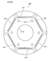
- FIG. 6 is a top view illustrating one of the first rotor cores (240) when viewed in the axial direction.
- the first rotor core (240) has six gaps (241) penetrating the first rotor core (240) in the axial direction. These gaps (241) face the magnet-housing slots (211) when the first rotor core (240) is placed on the second rotor core (250).
- the magnet-housing slots (211) individually associated with the gaps (241) are indicated by chain lines.
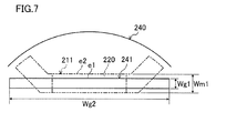
- FIG. 7 is an illustration showing a relationship in position and size between the magnet-housing slot (211) and the gap (241).
- the continuous lines represent the shape of the gap (241), and the chain lines represent the shape of the magnet-housing slot (211).
- the gap (241) is rectangular in FIG. 7 .
- the width (Wg2) of the gap (241) in the direction orthogonal to the radius extends to portions near the outer periphery of the first rotor core (240). This configuration can reduce a leakage magnetic flux occurring between adjacent magnetic poles.
- the gaps (241) have a magnetic resistance lower than that of the magnet-housing slots (211).
- the radial width (Wg1) i.e., a width along the radial direction
- the radial width (Wm1) of the magnet receiver (211a) is smaller than the radial width (Wm1) of the magnet receiver (211a).
- the magnetic resistance of the gap (241) is smaller than that of the magnet-housing slot (211).
- the gap (241) is positioned in such a manner that when viewed in the radial direction, a longer side (e1) at the outer peripheral side of the gap (241) is closer to the inner peripheral side than a longer side (e2) of the magnet receiver (211a) is.
- the radial width (Wg1) of the gap (241) is greater than or equal to the size of the air gap (G). This is because if the width (Wg1) were smaller than that of the air gap (G), a short circuit of a magnetic flux would be caused by the first rotor core (240).
- Each of the end plates (230) has a disk-shape, and is made of a non-magnetic metal such as stainless.
- Each of the end plates (230) and the first and second rotor cores (240 and 250) has six bolt holes (213).
- the bolt holes (213) penetrate the end plates (230) or the first or second rotor core (240 or 250) in the axial direction.
- the bolt holes (213) of one of the end plates (230) or the first or second rotor core (240 or 250) overlap with those of another of the end plates (230) or the first or second rotor core (240 or 250).
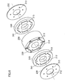
- FIG. 8 is a perspective view illustrating an assembly of the rotor (200) of this embodiment.
- the permanent magnets (220) are placed in the magnet receivers (211 a).
- each of the permanent magnets (220) is previously displaced, i.e., offset, inward from each axial end of the second rotor core (250).
- the permanent magnets (220) are fixed in advance to the second rotor core (250) by means of, for example, an adhesive, so as not to move in the magnet receiversre (211a).
- the first and second rotor cores (240 and 250) are arranged such that each of the first rotor cores (240) is located at an odd numbered position from an end and the second rotor core (250) is located at an even-numbered position from the end.
- the second rotor core (250) is sandwiched between the first rotor cores (240) in the axial direction. In this manner, the first rotor cores (240) are located at the first and third positions and the second rotor core (250) is located at the second position from an end of the rotor (200).
- the positions of the first rotor cores (240) and the second rotor core (250) are adjusted in relation to each other such that the magnet-housing slots (211) overlap with the gaps (241) of the first rotor cores (240) (see FIGS. 6 and 7 ).
- the first rotor cores (240) are placed on the second rotor core (250)
- the first rotor cores (240) are in contact with the second rotor core (250), but as described above, the axial ends of the permanent magnets (220) are displaced inward from the axial ends of the second rotor core (250), and thus, the permanent magnets (220) are not in contact with the first rotor cores (240).
- the end plates (230) are attached to the ends of the first rotor cores (240). Each of the end plates (230) is fixed to the rotor core (210) with six bolts (270) (see FIG. 1 ) penetrating the bolt holes (213).
- a shaft hole (212) is formed at the center of each of the first and second rotor cores (240 and 250).
- a driving shaft (300) of a metal such as iron is fitted in this shaft hole (212) by burning.
- the driving shaft (300) is used for driving a compression mechanism (not shown) in the electric compressor.
- FIG. 9 is an illustration of a flux path (an opposing magnetic field flux path) upon application of an opposing magnetic field.
- a flux path an opposing magnetic field flux path
- FIG. 9 illustrates a flux path (an opposing magnetic field flux path) upon application of an opposing magnetic field.
- an opposing magnetic field is applied to the rotor (200) of this embodiment and a magnetic flux is applied from the stator (100) onto magnetic core portions (240a and 250a) (see FIG. 5 ) at the outer peripheral sides of the permanent magnets (220).
- This magnetic flux travels toward the magnetic core portion (250a) near the permanent magnets (220) to some degree, but as indicated by the arrows in FIG. 9 , a large part of the magnetic flux travels toward the magnetic core portion (240a) of an associated one of the first rotor cores (240).
- the motor (10) of this embodiment exhibits a low strength of the opposing magnetic field applied on the permanent magnets (220), as compared to conventional motors.
- the motor (10) can generate a reluctance torque by using the first rotor cores (240). That is, in this embodiment, a reluctance torque in the first rotor cores (240) can compensate for a decrease in magnet torque.
- a motor including a rotor equipped with magnets can be provided with measures against demagnetization while reducing performance degradation of the motor.
- the magnet-housing slots (211) are covered with the first rotor cores (240).
- a cover for preventing detachment of the permanent magnets (220), for example, is not necessary.
- FIG. 10 is a sectional view illustrating a rotor (200) according to a second embodiment of the present invention.
- the rotor (200) of this embodiment includes a first rotor core (240) and a second rotor core (250).
- the height (H1) i.e., an axial dimension
- H2 the height of the second rotor core (250).
- the first rotor core (240) is in contact with the second rotor core (250) at their axial ends.
- measures against demagnetization can be provided in permanent magnets (220) near the first rotor core (240).
- the permanent magnets (220) can be easily inserted in magnet-housing slots (211) from an axial end of the second rotor core (250) that is not in contact with the first rotor core (240).
- a cover for preventing detachment of the permanent magnets (220), for example, is not necessary at the axial end of the second rotor core (250) that is not in contact with the first rotor core (240).
- FIG. 11 is a sectional view illustrating a rotor (200) according to a third embodiment of the present invention.
- the rotor (200) of this embodiment includes a first rotor core (240) and two second rotor cores (250).
- the first rotor core (240) is sandwiched between the second rotor cores (250) in the axial direction.
- the height (H1) i.e., an axial dimension
- H2 of the second rotor cores (250).
- the permanent magnets (220) can be inserted from both axial ends of the rotor (200).
- the rotor (200) can be easily fabricated.
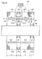
- FIG. 12 is a sectional view illustrating a rotor (200) according to a fourth embodiment of the present invention.
- the rotor (200) includes two first rotor cores (240) and two second rotor cores (250). These first and second rotor cores (240 and 250) are alternately stacked.
- the height (H1) i.e., an axial dimension
- H2 the height of the second rotor cores (250).
- FIG. 13 is a sectional view illustrating a rotor (200) according to a fifth embodiment of the present invention.
- the rotor (200) includes three first rotor cores (240) and two second rotor cores (250).
- the first rotor cores (240) and the second rotor cores (250) are alternately stacked.
- the height (H1) i.e., an axial dimension
- H2 the height of the second rotor cores (250).
- FIG. 14 is a top view illustrating a rotor (200) according to a sixth embodiment of the present invention.
- FIG. 15 is a sectional view illustrating the rotor (200) of the sixth embodiment.
- FIG. 15 corresponds to an A-A section of FIG. 14 .
- the rotor (200) of this embodiment includes a first rotor core (240) and two second rotor cores (250).
- the first rotor core (240) is sandwiched between the second rotor cores (250) in the axial direction.
- the height (H1) i.e., an axial dimension
- H2 height of the second rotor core
- permanent magnets (220) form multiple layers at each pole. Specifically, three layers of the permanent magnets (220) are provided at each pole.
- the outermost permanent magnet (220) of the rotor (200) is provided only in the second rotor cores (250).
- the second-layer and third-layer permanent magnets (220) from the outer peripheral side of the rotor (200) penetrate the first and second rotor cores (240 and 250).
- the first rotor core (240) has magnet-housing slots (211) connected to magnet-housing slots (211) of the second rotor cores (250) at positions corresponding to the second-layer and third-layer permanent magnets (220) from the outermost peripheral side.
- the gaps (241) are provided at the outermost peripheral side of the rotor (200) on which a strong opposing magnetic field can be applied, thereby providing measures against demagnetization of the permanent magnets (220) corresponding to the gaps (241).
- the first and second rotor cores (240 and 250) may be arranged in the manner described in the first, second, fourth, or fifth embodiment.
- An inner layer (e.g., the second layer) located inside the first layer may have gaps (241) similarly to those in the first layer, depending on the strength of the opposing magnetic field.
- gaps (241) are not limited to the above-described example.
- each of the embodiments may employ gaps (241) as follows.
- an end in the direction perpendicular to the radial direction, of the gap (241) preferably extends to a portion near the outer periphery of the first rotor core (240) as closely as possible. This is because this configuration is advantageous for reducing a leakage magnetic flux between adjacent poles.
- Each of the gaps (241) of the foregoing embodiments and variations may be displaced within a range where the gap (241) overlaps with the plane of the permanent magnets (220) projected in the axial direction.
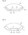
- the gaps (241) do not need to be symmetric with respect to the radius, as illustrated in, for example, FIG. 16 .
- the configurations of the gaps (241) described above may be appropriately combined.
- the number of division of the rotor core (210), i.e., the number of the first and second rotor cores (240 and 250) described above is merely an example.
- the first and second rotor cores (240 and 250) are not limited to multilayer cores (e.g., flat rolled magnetic steel sheets).
- the first and second rotor cores (240 and 250) may be made of a pressed-powder magnetic material.
- the rotor (200) may be configured by combining cores of different magnetic materials such that each first rotor core (240) is made of a pressed-powder magnetic material and each second rotor core (250) is made of a flat rolled magnetic steel sheet.
- the end plates (230) may be omitted.
- the end plates (230) for preventing detachment of magnets are made of a non-magnetic material or a magnetic material.
- the use of a non-magnetic material can lead to a cost increase, and the use of a magnetic material can cause a leakage of a magnet magnetic flux.
- omission of the end plates (230) can reduce the cost and/or increase the torque, advantageously.
- the present invention is applicable to generators as well as motors.
- the present invention is also applicable to rotary electric machines with distributed winding of a coil around a stator core.
- the present invention is useful for a rotor including a rotor core equipped with magnets and a rotary electric machine using such a rotor.
Landscapes
- Engineering & Computer Science (AREA)
- Power Engineering (AREA)
- Permanent Field Magnets Of Synchronous Machinery (AREA)
- Iron Core Of Rotating Electric Machines (AREA)
- Permanent Magnet Type Synchronous Machine (AREA)
Abstract
Description
- The present invention relates to rotors including rotor cores equipped with magnets and rotary electric machines using such rotors.
- Rotary electric machines, e.g., synchronous reluctance motors (SynRMs) employing auxiliary magnets, and interior permanent magnet motors (IPMs) include rotor cores equipped with magnets. Such a rotary electric machine occasionally shows reduction of magnetic force (i.e., demagnetization) of permanent magnets of the rotor core due to an application of a large opposing magnetic field caused for some reasons. To cope with this demagnetization, an increase in thickness of magnets, for example, may be effective. However, these measures disadvantageously lead to an increase in cost.
- Another example of measures against demagnetization is devising the path of a magnetic flux (see, for example, Patent Document 1). In this example, a magnetic member is disposed on the surface of a permanent magnet. An end ring of a magnetic material magnetically coupled to a rotor core is disposed near an end of the magnetic member with a gap left therebetween.
- [Patent Document 1] Japanese Unexamined Patent Publication No.
H08-51751 - In the example of Patent Document 1, however, the presence of a gap between the rotor body and the end ring reduces a room for the rotor core when the conventional size of the whole motor is to be kept. That is, the rotor core is downsized, and performance degradation of the motor might occur. On the other hand, if the conventional size of the rotor core is kept, the size of the whole motor increases, causing the possibility of an increase in cost.
- The present invention is focused on the above-described problems, and is intended to provide measures against demagnetization of magnets in a rotary electric machine including a rotor core equipped with the magnets while reducing degradation of performance of the machine.
- To solve the above-described problems, in an aspect of the present invention includes:
- a plurality of permanent magnets (220);
- a first rotor core (240) having a plurality of gaps (241) penetrating the first rotor core (240) along an axial direction; and
- a second rotor core (250) being in contact with an axial end of the first rotor core (240) and having a plurality of magnet-housing slots (211) associated with the gaps (241), wherein
- the gaps (241) have a magnetic resistance lower than that of the magnet-housing slots (211).
- In this configuration, upon application of an opposing magnetic field to the rotor (200), for example, this magnetic flux travels toward the permanent magnets (220) in the magnet-housing slots (211) to some extent, but a large part of the magnetic flux travels toward the first rotor core (240). This is because the magnetic resistance of the gaps (241) is lower than that of the magnet-housing slots (211). That is, the motor of the present invention can reduce the intensity of the magnetic field applied on the permanent magnets (220), as compared to conventional motors.
- In addition, since the first rotor core (240) is in contact with the second rotor core (250), a magnetic field from a stator (100) (which will be described later) is efficiently applied to the first rotor core (240). Thus, the first rotor core (240) is allowed to generate a reluctance torque.
- In a second aspect of the present invention,
in the rotor of the first aspect,
each of the gaps (241) has a radial width (Wg1) smaller than a radial width (Wm1) of an associated one of the magnet-housing slots (211). - In this configuration, the magnetic resistance of the gaps (241) is determined based on the radial width (Wg1) of the gaps (241).
- In a third aspect of the present invention,
in the rotor of the first or second aspect,
the first rotor core (240) has an axial dimension smaller than that of the second rotor core (250). - In this configuration, the magnet torque is dominant over the reluctance torque.
- In a fourth aspect of the present invention,
in the rotor of any one of the first through third aspects,
the second rotor core (250) is sandwiched between the first rotor cores (240) in the axial direction. - In this configuration, an application of an opposing magnetic field on the rotor (200) causes a large part of this magnetic flux toward both axial ends of the rotor (200). In addition, the magnet-housing slots (211) are covered with the first rotor core (240).
- In a fifth aspect of the present invention,
in the rotor of any one of the first through third aspects,
the first rotor core (240) is sandwiched between the second rotor cores (250) in the axial direction. - In this configuration, an application of an opposing magnetic field on the rotor (200) causes a large part of this magnetic flux to travel toward an axial center (a center in the axial direction) of the rotor (200).
- A rotary electric machine according to a sixth aspect of the present invention includes;
the rotor (200) of any one of the first through fifth aspects; and
a stator (100) including a stator core (110) around which a coil (120) is wound. - In a seventh aspect of the present invention, in the rotary electric machine of the sixth aspect,
each of the gaps (241) has a radial width (Wg1) larger than that of an air gap (G) between the rotor (200) and the stator (100). - In this configuration, since the width (Wg1) is larger than that of the air gap (G), a short circuit of a magnetic flux caused by the first rotor core (240) can be prevented.
- In the first aspect, the intensity of the opposing magnetic field applied on the permanent magnets (220) can be reduced, and a reluctance torque can be produced by the first rotor core (240). Thus, a rotary electric machine including a rotor having a rotor core equipped with magnets can be provided with measures against demagnetization while reducing performance degradation of the machine.
- In the second aspect, the magnetic resistance can be determined depending on a radial width (Wg1) of the gaps (241), thereby easily setting the magnetic resistance.
- In the fourth aspect, a large part of an opposing magnetic field applied on the rotor
- (200) travels toward both axial ends, and thus, measures against demagnetization can be obtained at both ends of the permanent magnets (220). In addition, since the magnet-housing slots (211) are covered with the first rotor core (240), a cover for preventing detachment of the permanent magnets (220), for example, can be omitted.
- In the fifth aspect, since a large part of the opposing magnetic field applied on the rotor (200) travels toward an axial center, measures against demagnetization can be obtained at the axial center of each of the permanent magnets (220). In this configuration, the permanent magnets (220) can be inserted from both axial ends of the rotor (200). Thus, the rotor (200) can be easily fabricated.
- In the seventh aspect, a short circuit of the magnetic flux can be prevented, thereby stably operating the rotary electric machine.
-
- [
FIG. 1] FIG. 1 is a transverse sectional view illustrating a motor according to a first embodiment of the present invention. - [
FIG. 2] FIG. 2 is a perspective view illustrating a stator of the first embodiment. - [
FIG. 3] FIG. 3 is a sectional view illustrating teeth when a stator core of the first embodiment is viewed from an inner peripheral side. - [
FIG. 4] FIG. 4 is a perspective view illustrating a rotor of the first embodiment. - [
FIG. 5] FIG. 5 is a sectional view illustrating the rotor of the first embodiment. - [
FIG. 6] FIG. 6 is a top view illustrating a first rotor core when viewed in the axial direction. - [
FIG. 7] FIG. 7 is an illustration showing a relationship in position and size between a magnet-housing slot and a gap. - [
FIG. 8] FIG. 8 is a perspective view illustrating an assembly of the rotor of the first embodiment. - [
FIG. 9] FIG. 9 is an illustration of a flux path (an opposing magnetic field flux path) upon application of an opposing magnetic field. - [
FIG. 10] FIG. 10 is a sectional view illustrating a rotor according to a second embodiment of the present invention. - [
FIG. 11] FIG. 11 is a sectional view illustrating a rotor according to a third embodiment of the present invention. - [
FIG. 12] FIG. 12 is a sectional view illustrating a rotor according to a fourth embodiment of the present invention. - [
FIG. 13] FIG. 13 is a sectional view illustrating a rotor according to a fifth embodiment of the present invention. - [
FIG. 14] FIG. 14 is a top view illustrating a rotor according to a sixth embodiment of the present invention. - [
FIG. 15] FIG. 15 is a sectional view illustrating the rotor of the sixth embodiment. - [
FIG. 16] FIG. 16 is a top view illustrating a first variation of the gap. - [
FIG. 17] FIG. 17 is a top view illustrating a second variation of the gap. - [
FIG. 18] FIG. 18 is a top view illustrating a third variation of the gap. - [
FIG. 19] FIG. 19 is a top view illustrating a fourth variation of the gap. - [
FIG. 20] FIG. 20 is a top view illustrating a fifth variation of the gap. - Embodiments of the present invention will be described hereinafter with reference to the drawings. The following embodiments are merely preferred examples in nature, and are not intended to limit the scope, applications, and use of the invention.
-
FIG. 1 is a transverse sectional view illustrating a motor (10) according to a first embodiment of the present invention. The motor (10) is used for, for example, an electric compressor (not shown) of an air conditioner. - As illustrated in
FIG. 1 , the motor (10) includes a stator (100), a rotor (200), and a driving shaft (300), and is housed in a casing (20) of the electric compressor. In the following description, the "axial direction" "or "axial" refers to the direction along the axis of the driving shaft (300), and the "radial direction" or "radial" refers to the direction orthogonal to the axis. The outer peripheral side refers to a distal side relative to the axis, whereas the inner peripheral side is a proximal side relative to the axis. - As illustrated in
FIG. 1 , the stator (100) a cylindrical stator core (110) and a coil (120). - The stator core (110) is a multilayer core obtained by forming a plate through punching of a flat rolled magnetic steel sheet (P) with press work and laminating such plates in the axial direction.
FIG. 2 is a perspective view illustrating the stator (100) of the first embodiment. As illustrated inFIGS. 1 and2 , the stator core (110) includes a back yoke (111), a plurality of (nine in this embodiment) teeth (112), and brims (113).FIG. 2 mainly illustrates one of the teeth (112). - As illustrated in
FIGS. 1 and2 , each of the teeth (112) is a rectangular portion of the stator core (110) extending in the radial direction. Space between each adjacent ones of the teeth (112) forms a slot (114) in which the coil (120) is housed. - The back yoke (111) has a ring shape. The back yoke (111) joins the teeth (112) together at outer peripheral sides of the teeth (112). In the stator core (110), the outer periphery of the back yoke (111) is fixed to the inner surface of the casing (20).
- The brims (113) are continuous to the inner peripheries of the teeth (112). Each of the brims (113) is wider than (i.e., has a peripheral length larger than that of) an associated one of the teeth (112). Each of the brims (113) forms a cylindrical surface at the inner peripheral side thereof. This cylindrical surface faces the outer peripheral surface (the cylindrical surface) of a rotor core (210), which will be described later, at a predetermined distance (i.e., with an air gap (G) provided between the cylindrical surface and the outer peripheral surface).
- A coil (120) is wound around each of the teeth (112) by a so-called concentrated winding technique. Specifically, the coil (120) is wound around each of the teeth (112), and the coil (120) wound is housed in associated ones of the slots (114).
FIG. 3 is a sectional view illustrating one of the teeth (112) when the stator core (110) of this embodiment is viewed from the inner peripheral side. As illustrated inFIG. 3 , insulators (161) are disposed at both axial sides of the tooth (112), and insulator films (160) are sandwiched between the coil (120) and the tooth (112). In this embodiment, the insulator films (160) are polyethylene terephthalate films. -
FIG. 4 is a perspective view illustrating the rotor (200) of the first embodiment.FIG. 5 is a sectional view illustrating the rotor (200) of the first embodiment. The rotor (200) includes a rotor core (210) (a magnetic core), a plurality of permanent magnets (220), and two end plates (230), and has a cylindrical shape. In this embodiment, the rotor (200) includes six permanent magnets (220).FIG. 4 does not show the end plates (230). - The rotor core (210) is a multilayer core obtained by forming a plate through punching of a flat rolled magnetic steel sheet (P) with press work and laminating such plates in the axial direction. As will be described in detail below, the rotor core (210) is divided, along the axial direction, into an odd number of (three in this embodiment) rotor cores that are in contact with one another. More specifically, the rotor core (210) is divided into three parts: two first rotor cores (240) each located at an odd numbered position from an end in the axial direction (i.e., an axial end) of the rotor core (210); and a second rotor core (250) located at an even-numbered position (see
FIG. 5 ). As illustrated inFIG. 5 , in this embodiment, the height (H1) (i.e., an axial dimension) of each of the first rotor cores (240) is smaller than the height (H2) of the second rotor core (250). - Now, configurations of, for example, the first and second rotor cores (240 and 250) will be described. In the following description, the first rotor cores (240) and the second rotor core (250) will be also referred to as divided rotor cores (240 and 250).
- As illustrated in, for example,
FIG. 4 , the second rotor core (250) has magnet-housing slots (211) individually housing the permanent magnets (220). The magnet-housing slots (211) are disposed at a pitch of 60° about the axis of the second rotor core (250). Each of the magnet-housing slots (211) has an approximately U shape when viewed in the axial direction, and penetrates the second rotor core (250) in the axial direction. More specifically, as illustrated inFIG. 4 , each of the magnet-housing slots (211) includes a magnet receiver (211a) orthogonal to the radius of the rotor core (210), and two barriers (211b) extending from the magnet receiver (211a) toward the outer peripheral side. The magnet receiver (211a) is rectangular when viewed inFIG. 1 , and receives an associated one of the permanent magnets (220). The axial height (the height in the axial direction) (Hm) of the permanent magnets (220) is smaller than the axial height (H2) of the second rotor core (250) (seeFIG. 5 ). -
FIG. 6 is a top view illustrating one of the first rotor cores (240) when viewed in the axial direction. As illustrated inFIG. 6 , the first rotor core (240) has six gaps (241) penetrating the first rotor core (240) in the axial direction. These gaps (241) face the magnet-housing slots (211) when the first rotor core (240) is placed on the second rotor core (250). InFIG. 6 , the magnet-housing slots (211) individually associated with the gaps (241) are indicated by chain lines. -
FIG. 7 is an illustration showing a relationship in position and size between the magnet-housing slot (211) and the gap (241). InFIG. 7 , the continuous lines represent the shape of the gap (241), and the chain lines represent the shape of the magnet-housing slot (211). In this embodiment, the gap (241) is rectangular inFIG. 7 . The width (Wg2) of the gap (241) in the direction orthogonal to the radius extends to portions near the outer periphery of the first rotor core (240). This configuration can reduce a leakage magnetic flux occurring between adjacent magnetic poles. - The gaps (241) have a magnetic resistance lower than that of the magnet-housing slots (211). In this embodiment, the radial width (Wg1) (i.e., a width along the radial direction) of the gap (241) is smaller than the radial width (Wm1) of the magnet receiver (211a). In this manner, in the radial direction, the magnetic resistance of the gap (241) is smaller than that of the magnet-housing slot (211). The gap (241) is positioned in such a manner that when viewed in the radial direction, a longer side (e1) at the outer peripheral side of the gap (241) is closer to the inner peripheral side than a longer side (e2) of the magnet receiver (211a) is. The radial width (Wg1) of the gap (241) is greater than or equal to the size of the air gap (G). This is because if the width (Wg1) were smaller than that of the air gap (G), a short circuit of a magnetic flux would be caused by the first rotor core (240).
- Each of the end plates (230) has a disk-shape, and is made of a non-magnetic metal such as stainless. Each of the end plates (230) and the first and second rotor cores (240 and 250) has six bolt holes (213). The bolt holes (213) penetrate the end plates (230) or the first or second rotor core (240 or 250) in the axial direction. When the end plates (230) and the first and second rotor cores (240 and 250) are placed on one another, the bolt holes (213) of one of the end plates (230) or the first or second rotor core (240 or 250) overlap with those of another of the end plates (230) or the first or second rotor core (240 or 250).
-
FIG. 8 is a perspective view illustrating an assembly of the rotor (200) of this embodiment. In the second rotor core (250), the permanent magnets (220) are placed in the magnet receivers (211 a). In this case, as illustrated inFIG. 5 , each of the permanent magnets (220) is previously displaced, i.e., offset, inward from each axial end of the second rotor core (250). The permanent magnets (220) are fixed in advance to the second rotor core (250) by means of, for example, an adhesive, so as not to move in the magnet receiversre (211a). - In the rotor (200), the first and second rotor cores (240 and 250) are arranged such that each of the first rotor cores (240) is located at an odd numbered position from an end and the second rotor core (250) is located at an even-numbered position from the end. In this embodiment, as illustrated in
FIG. 8 , the second rotor core (250) is sandwiched between the first rotor cores (240) in the axial direction. In this manner, the first rotor cores (240) are located at the first and third positions and the second rotor core (250) is located at the second position from an end of the rotor (200). In this case, the positions of the first rotor cores (240) and the second rotor core (250) are adjusted in relation to each other such that the magnet-housing slots (211) overlap with the gaps (241) of the first rotor cores (240) (seeFIGS. 6 and7 ). When the first rotor cores (240) are placed on the second rotor core (250), the first rotor cores (240) are in contact with the second rotor core (250), but as described above, the axial ends of the permanent magnets (220) are displaced inward from the axial ends of the second rotor core (250), and thus, the permanent magnets (220) are not in contact with the first rotor cores (240). - As illustrated in
FIG. 8 , the end plates (230) are attached to the ends of the first rotor cores (240). Each of the end plates (230) is fixed to the rotor core (210) with six bolts (270) (seeFIG. 1 ) penetrating the bolt holes (213). - A shaft hole (212) is formed at the center of each of the first and second rotor cores (240 and 250). A driving shaft (300) of a metal such as iron is fitted in this shaft hole (212) by burning. The driving shaft (300) is used for driving a compression mechanism (not shown) in the electric compressor.
-
FIG. 9 is an illustration of a flux path (an opposing magnetic field flux path) upon application of an opposing magnetic field. For example, suppose that an opposing magnetic field is applied to the rotor (200) of this embodiment and a magnetic flux is applied from the stator (100) onto magnetic core portions (240a and 250a) (seeFIG. 5 ) at the outer peripheral sides of the permanent magnets (220). This magnetic flux travels toward the magnetic core portion (250a) near the permanent magnets (220) to some degree, but as indicated by the arrows inFIG. 9 , a large part of the magnetic flux travels toward the magnetic core portion (240a) of an associated one of the first rotor cores (240). This is because the magnetic resistance of the gaps (241) of the first rotor cores (240) is lower than that of the magnet-housing slots (211). That is, the motor (10) of this embodiment exhibits a low strength of the opposing magnetic field applied on the permanent magnets (220), as compared to conventional motors. Thus, in this embodiment, it is possible to provide measures against demagnetization of the permanent magnets (220) caused by an opposing magnetic field. - In this embodiment, if the size of the motor (10) is to be made equal to that of a conventional motor, the axial length (i.e., the length along the axial direction) (Hm) of the permanent magnets (220) decreases by an amount corresponding to the first rotor cores (240), and thus, a decrease in magnet torque is expected. However, since the first rotor cores (240) are in contact with the second rotor core (250), a magnetic field from the stator (100) is efficiently applied on the first rotor cores (240). Accordingly, the motor (10) can generate a reluctance torque by using the first rotor cores (240). That is, in this embodiment, a reluctance torque in the first rotor cores (240) can compensate for a decrease in magnet torque.
- In the manner described above, in this embodiment, a motor including a rotor equipped with magnets can be provided with measures against demagnetization while reducing performance degradation of the motor.
- In addition, the magnet-housing slots (211) are covered with the first rotor cores (240). Thus, a cover for preventing detachment of the permanent magnets (220), for example, is not necessary.
-
FIG. 10 is a sectional view illustrating a rotor (200) according to a second embodiment of the present invention. The rotor (200) of this embodiment includes a first rotor core (240) and a second rotor core (250). In this embodiment, the height (H1) (i.e., an axial dimension) of the first rotor core (240) is also smaller than the height (H2) of the second rotor core (250). The first rotor core (240) is in contact with the second rotor core (250) at their axial ends. - In this configuration of this embodiment, even upon an application of an opposing magnetic field on the rotor (200), a large part of the magnetic flux travels toward a magnetic core portion (240a) near the first rotor core (240). Thus, in this embodiment, measures against demagnetization can be provided in permanent magnets (220) near the first rotor core (240). In the second rotor core (250), the permanent magnets (220) can be easily inserted in magnet-housing slots (211) from an axial end of the second rotor core (250) that is not in contact with the first rotor core (240). In addition, a cover for preventing detachment of the permanent magnets (220), for example, is not necessary at the axial end of the second rotor core (250) that is not in contact with the first rotor core (240).
-
FIG. 11 is a sectional view illustrating a rotor (200) according to a third embodiment of the present invention. The rotor (200) of this embodiment includes a first rotor core (240) and two second rotor cores (250). The first rotor core (240) is sandwiched between the second rotor cores (250) in the axial direction. In this embodiment, the height (H1) (i.e., an axial dimension) of the first rotor core (240) is also smaller than the height (H2) of the second rotor cores (250). - In this configuration of the third embodiment, even upon an application of an opposing magnetic field on the rotor (200), a large part of the magnetic flux travels toward a magnetic core portion (240a) near the first rotor core (240). Thus, measures against demagnetization of permanent magnets (220) can be provided near the axial center of rotor (200) on which a relatively strong opposing magnetic field is likely to be applied.
- In addition, the permanent magnets (220) can be inserted from both axial ends of the rotor (200). Thus, the rotor (200) can be easily fabricated.
-
FIG. 12 is a sectional view illustrating a rotor (200) according to a fourth embodiment of the present invention. In this embodiment, the rotor (200) includes two first rotor cores (240) and two second rotor cores (250). These first and second rotor cores (240 and 250) are alternately stacked. In this embodiment, the height (H1) (i.e., an axial dimension) of the first rotor cores (240) is also smaller than the height (H2) of the second rotor cores (250). In this configuration, upon an application of an opposing magnetic field on the rotor (200), a large part of the magnetic flux travels toward magnetic core portions (240a) near the first rotor cores (240). Thus, in this embodiment, it is also possible to provide measures against demagnetization while reducing performance degradation of the motor. -
FIG. 13 is a sectional view illustrating a rotor (200) according to a fifth embodiment of the present invention. In this embodiment, the rotor (200) includes three first rotor cores (240) and two second rotor cores (250). The first rotor cores (240) and the second rotor cores (250) are alternately stacked. In this embodiment, the height (H1) (i.e., an axial dimension) of the first rotor cores (240) is also smaller than the height (H2) of the second rotor cores (250). In this configuration, upon an application of an opposing magnetic field on the rotor (200), a large part of the magnetic flux travels toward magnetic core portions (240a) near the first rotor cores (240). Thus, in this embodiment, it is also possible to provide measures against demagnetization while reducing performance degradation of the motor. -
FIG. 14 is a top view illustrating a rotor (200) according to a sixth embodiment of the present invention.FIG. 15 is a sectional view illustrating the rotor (200) of the sixth embodiment.FIG. 15 corresponds to an A-A section ofFIG. 14 . As illustrated inFIG. 15 , the rotor (200) of this embodiment includes a first rotor core (240) and two second rotor cores (250). The first rotor core (240) is sandwiched between the second rotor cores (250) in the axial direction. In this embodiment, the height (H1) (i.e., an axial dimension) of the first rotor core (240) is also smaller than the height (H2) of the second rotor core (250). - In the rotor (200) of this embodiment, permanent magnets (220) form multiple layers at each pole. Specifically, three layers of the permanent magnets (220) are provided at each pole. The outermost permanent magnet (220) of the rotor (200) is provided only in the second rotor cores (250). The second-layer and third-layer permanent magnets (220) from the outer peripheral side of the rotor (200) penetrate the first and second rotor cores (240 and 250).
- To obtain the multilayer configuration of the permanent magnets (220), multiple layers of magnet-housing slots (211) are provided in the second rotor cores (250). In the first rotor core (240), gaps (241) are provided only at the position corresponding to the outermost permanent magnets (220). Instead of the gaps (241), the first rotor core (240) has magnet-housing slots (211) connected to magnet-housing slots (211) of the second rotor cores (250) at positions corresponding to the second-layer and third-layer permanent magnets (220) from the outermost peripheral side.
- As described above, the gaps (241) are provided at the outermost peripheral side of the rotor (200) on which a strong opposing magnetic field can be applied, thereby providing measures against demagnetization of the permanent magnets (220) corresponding to the gaps (241).
- In a case where multiple layers of the permanent magnets (220) are provided at each pole as in this embodiment, the first and second rotor cores (240 and 250) may be arranged in the manner described in the first, second, fourth, or fifth embodiment.
- An inner layer (e.g., the second layer) located inside the first layer may have gaps (241) similarly to those in the first layer, depending on the strength of the opposing magnetic field.
- The shape of the gaps (241) is not limited to the above-described example. For example, each of the embodiments may employ gaps (241) as follows.
- <1>
FIG. 16 is a top view illustrating a first variation of the gap (241). The gap (241) illustrated inFIG. 16 is a through hole whose cross-sectional shape (i.e., the shape projected in the axial direction) extends along the magnet-housing slot (211) and whose width is smaller than that of the magnet-housing slot (211). In this variation, ends (241a) of the gap (241) extend to positions near the outer periphery of the first rotor core (240). - <2>
FIG. 17 is a top view illustrating a second variation of the gap (241). In the variation illustrated inFIG. 17 , regarding the shape of the gap (241) projected in the axial direction, the radial width (Wg1) of the gap (241) is smaller than the radial width (Wm1) of the magnet receiver (211a) in a portion of the gap (241) overlapping with the magnet receiver (211a), and the gap (241) substantially extends along the barrier (211b) at a tip of the barrier (211b). In this variation, the longer side (e1) of the gap (241) at the outer peripheral side coincides with the longer side (e2) of the magnet receiver (211a). Alternatively, the positional relationship between the gap (241) and the magnet-housing slot (211) may be determined in relation to each other such that the longer sides at the inner peripheral sides thereof coincide with each other. - <3>
FIG. 18 is a top view illustrating a third variation of the gap (241). In the variation illustrated inFIG. 18 , regarding the shape of the gap (241) projected in the axial direction, a width (Wg3) of the gap (241) is smaller than the width of the barrier (211b) in a portion of the gap (241) overlapping with the barrier (211b), and is equal to, or larger than, the width (Wm1) of the magnet receiver (211a) in a portion of the gap (241) overlapping with the magnet receiver (211a).FIG. 18 illustrates an example in which the width (Wg1) is larger than the width (Wm1). - <4>
FIG. 19 is a top view illustrating a fourth variation of the gap (241). In the variation ofFIG. 19 , regarding the shape of the gap (241) projected in the axial direction, a portion of the gap (241) near the center thereof is recessed toward the inner peripheral side in a portion of the gap (241) overlapping with the magnet receiver (211a). Thus, the radial width (Wg1) of the gap (241) is smaller than the radial width (Wm1) of the magnet-housing slot (211). The gap (241) substantially overlaps with the barrier (211b) in a portion of the gap (241) overlapping with the barrier (211b). - <5>
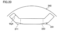
FIG. 20 is a top view illustrating a fifth variation of the gap (241). In the variation illustrated inFIG. 20 , regarding the shape of the gap (241) projected in the axial direction, the inner peripheral side line near both ends of the magnet receiver (211a) is moved toward the outer peripheral side. Thus, the width (Wg4) of the gap (241) near an end of the magnet receiver (211a) is smaller than the width near the center of the magnet-housing slot (211). In the example ofFIG. 20 , the inner peripheral side line of the gap (241) is moved toward the outer peripheral side. Alternatively, the outer peripheral side line may be moved toward the inner peripheral side or moved from both of the inner and outer peripheral sides. - In either example, an end (e.g., the end (241a)), in the direction perpendicular to the radial direction, of the gap (241) preferably extends to a portion near the outer periphery of the first rotor core (240) as closely as possible. This is because this configuration is advantageous for reducing a leakage magnetic flux between adjacent poles.
- Each of the gaps (241) of the foregoing embodiments and variations may be displaced within a range where the gap (241) overlaps with the plane of the permanent magnets (220) projected in the axial direction. The gaps (241) do not need to be symmetric with respect to the radius, as illustrated in, for example,
FIG. 16 . The configurations of the gaps (241) described above may be appropriately combined. - The number of division of the rotor core (210), i.e., the number of the first and second rotor cores (240 and 250) described above is merely an example.
- The first and second rotor cores (240 and 250) are not limited to multilayer cores (e.g., flat rolled magnetic steel sheets). For example, the first and second rotor cores (240 and 250) may be made of a pressed-powder magnetic material. In such a case, the rotor (200) may be configured by combining cores of different magnetic materials such that each first rotor core (240) is made of a pressed-powder magnetic material and each second rotor core (250) is made of a flat rolled magnetic steel sheet.
- In the foregoing embodiments, the end plates (230) may be omitted. The end plates (230) for preventing detachment of magnets are made of a non-magnetic material or a magnetic material. In these cases, the use of a non-magnetic material can lead to a cost increase, and the use of a magnetic material can cause a leakage of a magnet magnetic flux. Thus, omission of the end plates (230) can reduce the cost and/or increase the torque, advantageously.
- The present invention is applicable to generators as well as motors.
- The present invention is also applicable to rotary electric machines with distributed winding of a coil around a stator core.
- The present invention is useful for a rotor including a rotor core equipped with magnets and a rotary electric machine using such a rotor.
-
- 1
- motor (rotary electric machine)
- 100
- stator
- 110
- stator core
- 120
- coil
- 200
- rotor
- 210
- rotor core
- 211
- magnet-housing slot
- 220
- magnet
- 240
- first rotor core
- 241
- gap
- 250
- second rotor core
Claims (7)
- A rotor comprising:a plurality of permanent magnets (220);a first rotor core (240) having a plurality of gaps (241) penetrating the first rotor core (240) along an axial direction; anda second rotor core (250) being in contact with an axial end of the first rotor core (240) and having a plurality of magnet-housing slots (211) associated with the gaps (241), whereinthe gaps (241) have a magnetic resistance lower than that of the magnet-housing slots (211).
- The rotor of claim 1, wherein
each of the gaps (241) has a radial width (Wg1) smaller than a radial width (Wm1) of an associated one of the magnet-housing slots (211). - The rotor of claim 1, wherein
the first rotor core (240) has an axial dimension smaller than that of the second rotor core (250). - The rotor of claim 1, wherein
the second rotor core (250) is sandwiched between the first rotor cores (240) in the axial direction. - The rotor of claim 1,
the first rotor core (240) is sandwiched between the second rotor cores (250) in the axial direction. - A rotary electric machine comprising;
the rotor (200) of claim 1; and
a stator (100) including a stator core (110) around which a coil (120) is wound. - The rotary electric machine of claim 6, wherein
each of the gaps (241) has a radial width (Wg1) larger than that of an air gap (G) between the rotor (200) and the stator (100).
Applications Claiming Priority (2)
| Application Number | Priority Date | Filing Date | Title |
|---|---|---|---|
| JP2011077880 | 2011-03-31 | ||
| PCT/JP2012/001949 WO2012132331A1 (en) | 2011-03-31 | 2012-03-21 | Rotor and rotating electrical mechanism using same |
Publications (3)
| Publication Number | Publication Date |
|---|---|
| EP2693605A1 true EP2693605A1 (en) | 2014-02-05 |
| EP2693605A4 EP2693605A4 (en) | 2016-03-23 |
| EP2693605B1 EP2693605B1 (en) | 2017-07-19 |
Family
ID=46930116
Family Applications (1)
| Application Number | Title | Priority Date | Filing Date |
|---|---|---|---|
| EP12763654.6A Active EP2693605B1 (en) | 2011-03-31 | 2012-03-21 | Rotor and rotating electrical mechanism using same |
Country Status (6)
| Country | Link |
|---|---|
| US (1) | US9712006B2 (en) |
| EP (1) | EP2693605B1 (en) |
| JP (1) | JP5234202B2 (en) |
| CN (1) | CN103430430B (en) |
| ES (1) | ES2635600T3 (en) |
| WO (1) | WO2012132331A1 (en) |
Cited By (2)
| Publication number | Priority date | Publication date | Assignee | Title |
|---|---|---|---|---|
| EP3349333A1 (en) * | 2017-01-11 | 2018-07-18 | Toyota Jidosha Kabushiki Kaisha | Rotary electric-machine rotor |
| IT201700100814A1 (en) * | 2017-09-08 | 2019-03-08 | S M E S P A | Procedure for the assembly of a rotor of a synchronous motor with variable reluctance and this rotor |
Families Citing this family (23)
| Publication number | Priority date | Publication date | Assignee | Title |
|---|---|---|---|---|
| EP2916434B1 (en) * | 2012-11-01 | 2017-07-19 | Mitsubishi Electric Corporation | Electric motor with embedded permanent magnet, compressor, and refrigeration and air conditioning equipment |
| US10481211B2 (en) * | 2014-01-15 | 2019-11-19 | Lat Enterprises, Inc. | State-of-charge indicator |
| JP2015154665A (en) * | 2014-02-18 | 2015-08-24 | 株式会社ジェイテクト | Rotor and rotor manufacturing method |
| GB2562859B (en) * | 2016-01-27 | 2022-07-06 | Mitsubishi Electric Corp | Magnetizing method, rotor, motor, and scroll compressor |
| KR102018013B1 (en) * | 2016-01-27 | 2019-09-03 | 미쓰비시덴키 가부시키가이샤 | Rotor, magnetizing method, electric motor and scroll compressor |
| EP3255758A1 (en) * | 2016-06-07 | 2017-12-13 | Siemens Aktiengesellschaft | Rotor for a reluctance machine |
| CN106253615B (en) * | 2016-08-26 | 2019-01-08 | 广东威灵电机制造有限公司 | Motor |
| KR101961142B1 (en) * | 2017-01-02 | 2019-03-25 | 엘지전자 주식회사 | Electric motor and manufacturing method for rotor thereof |
| US20190165626A1 (en) * | 2017-06-05 | 2019-05-30 | Top Co., Ltd. | Rotor and rotary machine |
| JP2019161698A (en) * | 2018-03-07 | 2019-09-19 | 本田技研工業株式会社 | Rotor assembly of rotary electric machine, and rotary electric machine thereof |
| ES2948863T3 (en) | 2018-03-12 | 2023-09-20 | Mitsubishi Electric Corp | Electric motor, compressor, fan and refrigeration and air conditioning apparatus |
| EP3783773B1 (en) * | 2018-06-20 | 2023-04-12 | Guangdong Meizhi Compressor Co., Ltd. | Rotor, motor and compressor |
| CN108768015B (en) * | 2018-07-20 | 2020-04-17 | 珠海格力电器股份有限公司 | Rotor assembly and motor |
| CN110875659A (en) * | 2018-08-30 | 2020-03-10 | 广东美芝制冷设备有限公司 | Rotating electrical machine rotors, motors and compressors |
| WO2020170418A1 (en) * | 2019-02-22 | 2020-08-27 | 三菱電機株式会社 | Motor, compressor, and air conditioning device |
| WO2020201937A1 (en) * | 2019-03-29 | 2020-10-08 | The Trustees For The Time Being Of The Kmn Fulfilment Trust | An electric power machine with a rotor member comprising magnetite |
| EP3780350B1 (en) * | 2019-08-14 | 2022-07-13 | Secop GmbH | Interior permanent magnet rotor for a refrigerant compressor |
| DE102019129243A1 (en) * | 2019-10-30 | 2021-05-06 | Valeo Siemens Eautomotive Germany Gmbh | Electric machine rotor, associated manufacturing process, and electric machine for driving a vehicle |
| WO2021260882A1 (en) * | 2020-06-25 | 2021-12-30 | 三菱電機株式会社 | Electric motor, compressor, and refrigeration cycle device |
| CN112436689B (en) * | 2020-12-18 | 2022-09-13 | 山东理工大学 | Production method of nested drive motor salient pole rotor with backstop function |
| CN219181380U (en) | 2022-12-14 | 2023-06-13 | 日本电产株式会社 | Synchronous reluctance motor |
| US20250119009A1 (en) * | 2023-10-09 | 2025-04-10 | GM Global Technology Operations LLC | Rotor for electric machine |
| US12573927B2 (en) * | 2023-10-10 | 2026-03-10 | GM Global Technology Operations LLC | Hybrid rotor for synchronous machine |
Family Cites Families (12)
| Publication number | Priority date | Publication date | Assignee | Title |
|---|---|---|---|---|
| JPH0851751A (en) | 1994-08-10 | 1996-02-20 | Toshiba Corp | Permanent magnet type rotating electric machine |
| US5808392A (en) | 1994-04-28 | 1998-09-15 | Kabushiki Kaisha Toshiba | Permanent magnet type rotating machine |
| CN2264439Y (en) * | 1996-05-06 | 1997-10-08 | 韩泰勋 | Axial phase-tandem a.c low speed synchronous motor |
| JPH1189145A (en) * | 1997-09-10 | 1999-03-30 | Fujitsu General Ltd | Permanent magnet type motor |
| US6727627B1 (en) * | 1999-07-16 | 2004-04-27 | Matsushita Electric Industrial Co., Ltd. | Permanent magnet synchronous motor |
| JP2002354730A (en) | 2001-05-25 | 2002-12-06 | Hitachi Ltd | Permanent magnet type rotating electric machine |
| JP2002354729A (en) * | 2001-05-25 | 2002-12-06 | Hitachi Ltd | Permanent magnet type rotating electric machine and air conditioner using the same |
| JP2004088852A (en) * | 2002-08-23 | 2004-03-18 | Daikin Ind Ltd | Electric motor and compressor using the same |
| JP2006014473A (en) * | 2004-06-25 | 2006-01-12 | Aisin Seiki Co Ltd | motor |
| JP5130679B2 (en) * | 2006-09-07 | 2013-01-30 | 株式会社明電舎 | Forward salient pole motor |
| DE102006056873A1 (en) * | 2006-12-01 | 2008-06-05 | Siemens Ag | Permanent magnet rotor with bends for fixing the permanent magnets of the rotor package |
| EP2676356A1 (en) * | 2011-02-17 | 2013-12-25 | CERN - European Organization For Nuclear Research | A system and method for positioning and fixing objects relative to each other |
-
2012
- 2012-03-21 US US14/008,386 patent/US9712006B2/en active Active
- 2012-03-21 CN CN201280013249.5A patent/CN103430430B/en active Active
- 2012-03-21 JP JP2012063266A patent/JP5234202B2/en active Active
- 2012-03-21 WO PCT/JP2012/001949 patent/WO2012132331A1/en not_active Ceased
- 2012-03-21 ES ES12763654.6T patent/ES2635600T3/en active Active
- 2012-03-21 EP EP12763654.6A patent/EP2693605B1/en active Active
Cited By (5)
| Publication number | Priority date | Publication date | Assignee | Title |
|---|---|---|---|---|
| EP3349333A1 (en) * | 2017-01-11 | 2018-07-18 | Toyota Jidosha Kabushiki Kaisha | Rotary electric-machine rotor |
| IT201700100814A1 (en) * | 2017-09-08 | 2019-03-08 | S M E S P A | Procedure for the assembly of a rotor of a synchronous motor with variable reluctance and this rotor |
| EP3454458A1 (en) * | 2017-09-08 | 2019-03-13 | S.M.E S.p.A. | A process for assembling a rotor of a variable-reluctance synchronous motor, and the rotor |
| CN109474139A (en) * | 2017-09-08 | 2019-03-15 | Sme个人有限责任公司 | The assembly method and rotor of the rotor of variable reluctance synchronous motor |
| US11699929B2 (en) | 2017-09-08 | 2023-07-11 | Dana Tm4 Italia S.R.L. | Rotor of a variable-reluctance synchronous motor |
Also Published As
| Publication number | Publication date |
|---|---|
| EP2693605B1 (en) | 2017-07-19 |
| JP2013034362A (en) | 2013-02-14 |
| WO2012132331A1 (en) | 2012-10-04 |
| CN103430430A (en) | 2013-12-04 |
| CN103430430B (en) | 2016-08-17 |
| US20140021820A1 (en) | 2014-01-23 |
| EP2693605A4 (en) | 2016-03-23 |
| ES2635600T3 (en) | 2017-10-04 |
| JP5234202B2 (en) | 2013-07-10 |
| US9712006B2 (en) | 2017-07-18 |
Similar Documents
| Publication | Publication Date | Title |
|---|---|---|
| EP2693605B1 (en) | Rotor and rotating electrical mechanism using same | |
| JP5933743B2 (en) | Permanent magnet embedded motor, compressor, and refrigeration air conditioner | |
| CN108292866B (en) | Motor and method for manufacturing motor | |
| CN102959833B (en) | Laminated cores for rotating electrical machines | |
| CN202721584U (en) | Permanent-magnet synchronous motor and compressor, hybrid electrical vehicle (HEV), electric vehicle (EV) and fuel cell vehicle embarked with the same | |
| EP2216883A1 (en) | Rotary machine rotor | |
| WO2021235267A1 (en) | Rotor and electric motor | |
| JP2012217278A (en) | Permanent magnet type rotary electric machine and manufacturing method therefor | |
| JP2012213268A (en) | Rotary electric machine | |
| US9172293B2 (en) | Hybrid stepping motor | |
| JPWO2015098159A1 (en) | Magnetic inductor type motor and method of manufacturing the same | |
| JPWO2017212575A1 (en) | Permanent magnet motor | |
| JP4515236B2 (en) | Embedded magnet type rotor | |
| JP2003319575A (en) | Synchronous machine stator core | |
| US20210273503A1 (en) | Rotor, and rotary electric machine provided with same | |
| JP2013236418A (en) | Rotary electric machine | |
| JP4568639B2 (en) | Stator | |
| JP7224987B2 (en) | Rotating electric machine | |
| JP2006254561A (en) | Rotating electric machine | |
| JP5720375B2 (en) | Rotating electrical machine | |
| JP5729090B2 (en) | Rotor and rotating electrical machine | |
| US20250202293A1 (en) | Stator of an electric rotating machine, electric rotating machine, and geared motor unit | |
| US20250392177A1 (en) | Rotor and electric machine | |
| US20240213835A1 (en) | Motor | |
| JP7224986B2 (en) | Rotating electric machine |
Legal Events
| Date | Code | Title | Description |
|---|---|---|---|
| PUAI | Public reference made under article 153(3) epc to a published international application that has entered the european phase |
Free format text: ORIGINAL CODE: 0009012 |
|
| 17P | Request for examination filed |
Effective date: 20131016 |
|
| AK | Designated contracting states |
Kind code of ref document: A1 Designated state(s): AL AT BE BG CH CY CZ DE DK EE ES FI FR GB GR HR HU IE IS IT LI LT LU LV MC MK MT NL NO PL PT RO RS SE SI SK SM TR |
|
| DAX | Request for extension of the european patent (deleted) | ||
| RA4 | Supplementary search report drawn up and despatched (corrected) |
Effective date: 20160218 |
|
| RIC1 | Information provided on ipc code assigned before grant |
Ipc: H02K 1/27 20060101AFI20160212BHEP Ipc: H02K 19/10 20060101ALI20160212BHEP Ipc: H02K 1/24 20060101ALI20160212BHEP Ipc: H02K 1/22 20060101ALI20160212BHEP |
|
| GRAP | Despatch of communication of intention to grant a patent |
Free format text: ORIGINAL CODE: EPIDOSNIGR1 |
|
| STAA | Information on the status of an ep patent application or granted ep patent |
Free format text: STATUS: GRANT OF PATENT IS INTENDED |
|
| INTG | Intention to grant announced |
Effective date: 20170329 |
|
| GRAS | Grant fee paid |
Free format text: ORIGINAL CODE: EPIDOSNIGR3 |
|
| GRAA | (expected) grant |
Free format text: ORIGINAL CODE: 0009210 |
|
| STAA | Information on the status of an ep patent application or granted ep patent |
Free format text: STATUS: THE PATENT HAS BEEN GRANTED |
|
| AK | Designated contracting states |
Kind code of ref document: B1 Designated state(s): AL AT BE BG CH CY CZ DE DK EE ES FI FR GB GR HR HU IE IS IT LI LT LU LV MC MK MT NL NO PL PT RO RS SE SI SK SM TR |
|
| REG | Reference to a national code |
Ref country code: GB Ref legal event code: FG4D |
|
| REG | Reference to a national code |
Ref country code: CH Ref legal event code: EP |
|
| REG | Reference to a national code |
Ref country code: IE Ref legal event code: FG4D |
|
| REG | Reference to a national code |
Ref country code: AT Ref legal event code: REF Ref document number: 911276 Country of ref document: AT Kind code of ref document: T Effective date: 20170815 |
|
| REG | Reference to a national code |
Ref country code: DE Ref legal event code: R096 Ref document number: 602012034741 Country of ref document: DE |
|
| REG | Reference to a national code |
Ref country code: ES Ref legal event code: FG2A Ref document number: 2635600 Country of ref document: ES Kind code of ref document: T3 Effective date: 20171004 |
|
| REG | Reference to a national code |
Ref country code: NL Ref legal event code: MP Effective date: 20170719 |
|
| REG | Reference to a national code |
Ref country code: LT Ref legal event code: MG4D |
|
| REG | Reference to a national code |
Ref country code: AT Ref legal event code: MK05 Ref document number: 911276 Country of ref document: AT Kind code of ref document: T Effective date: 20170719 |
|
| PG25 | Lapsed in a contracting state [announced via postgrant information from national office to epo] |
Ref country code: SE Free format text: LAPSE BECAUSE OF FAILURE TO SUBMIT A TRANSLATION OF THE DESCRIPTION OR TO PAY THE FEE WITHIN THE PRESCRIBED TIME-LIMIT Effective date: 20170719 Ref country code: HR Free format text: LAPSE BECAUSE OF FAILURE TO SUBMIT A TRANSLATION OF THE DESCRIPTION OR TO PAY THE FEE WITHIN THE PRESCRIBED TIME-LIMIT Effective date: 20170719 Ref country code: LT Free format text: LAPSE BECAUSE OF FAILURE TO SUBMIT A TRANSLATION OF THE DESCRIPTION OR TO PAY THE FEE WITHIN THE PRESCRIBED TIME-LIMIT Effective date: 20170719 Ref country code: NO Free format text: LAPSE BECAUSE OF FAILURE TO SUBMIT A TRANSLATION OF THE DESCRIPTION OR TO PAY THE FEE WITHIN THE PRESCRIBED TIME-LIMIT Effective date: 20171019 Ref country code: FI Free format text: LAPSE BECAUSE OF FAILURE TO SUBMIT A TRANSLATION OF THE DESCRIPTION OR TO PAY THE FEE WITHIN THE PRESCRIBED TIME-LIMIT Effective date: 20170719 Ref country code: AT Free format text: LAPSE BECAUSE OF FAILURE TO SUBMIT A TRANSLATION OF THE DESCRIPTION OR TO PAY THE FEE WITHIN THE PRESCRIBED TIME-LIMIT Effective date: 20170719 Ref country code: NL Free format text: LAPSE BECAUSE OF FAILURE TO SUBMIT A TRANSLATION OF THE DESCRIPTION OR TO PAY THE FEE WITHIN THE PRESCRIBED TIME-LIMIT Effective date: 20170719 |
|
| PG25 | Lapsed in a contracting state [announced via postgrant information from national office to epo] |
Ref country code: IS Free format text: LAPSE BECAUSE OF FAILURE TO SUBMIT A TRANSLATION OF THE DESCRIPTION OR TO PAY THE FEE WITHIN THE PRESCRIBED TIME-LIMIT Effective date: 20171119 Ref country code: BG Free format text: LAPSE BECAUSE OF FAILURE TO SUBMIT A TRANSLATION OF THE DESCRIPTION OR TO PAY THE FEE WITHIN THE PRESCRIBED TIME-LIMIT Effective date: 20171019 Ref country code: PL Free format text: LAPSE BECAUSE OF FAILURE TO SUBMIT A TRANSLATION OF THE DESCRIPTION OR TO PAY THE FEE WITHIN THE PRESCRIBED TIME-LIMIT Effective date: 20170719 Ref country code: GR Free format text: LAPSE BECAUSE OF FAILURE TO SUBMIT A TRANSLATION OF THE DESCRIPTION OR TO PAY THE FEE WITHIN THE PRESCRIBED TIME-LIMIT Effective date: 20171020 Ref country code: LV Free format text: LAPSE BECAUSE OF FAILURE TO SUBMIT A TRANSLATION OF THE DESCRIPTION OR TO PAY THE FEE WITHIN THE PRESCRIBED TIME-LIMIT Effective date: 20170719 Ref country code: RS Free format text: LAPSE BECAUSE OF FAILURE TO SUBMIT A TRANSLATION OF THE DESCRIPTION OR TO PAY THE FEE WITHIN THE PRESCRIBED TIME-LIMIT Effective date: 20170719 |
|
| REG | Reference to a national code |
Ref country code: FR Ref legal event code: PLFP Year of fee payment: 7 |
|
| REG | Reference to a national code |
Ref country code: DE Ref legal event code: R097 Ref document number: 602012034741 Country of ref document: DE |
|
| PG25 | Lapsed in a contracting state [announced via postgrant information from national office to epo] |
Ref country code: DK Free format text: LAPSE BECAUSE OF FAILURE TO SUBMIT A TRANSLATION OF THE DESCRIPTION OR TO PAY THE FEE WITHIN THE PRESCRIBED TIME-LIMIT Effective date: 20170719 Ref country code: RO Free format text: LAPSE BECAUSE OF FAILURE TO SUBMIT A TRANSLATION OF THE DESCRIPTION OR TO PAY THE FEE WITHIN THE PRESCRIBED TIME-LIMIT Effective date: 20170719 Ref country code: CZ Free format text: LAPSE BECAUSE OF FAILURE TO SUBMIT A TRANSLATION OF THE DESCRIPTION OR TO PAY THE FEE WITHIN THE PRESCRIBED TIME-LIMIT Effective date: 20170719 |
|
| PLBE | No opposition filed within time limit |
Free format text: ORIGINAL CODE: 0009261 |
|
| STAA | Information on the status of an ep patent application or granted ep patent |
Free format text: STATUS: NO OPPOSITION FILED WITHIN TIME LIMIT |
|
| PG25 | Lapsed in a contracting state [announced via postgrant information from national office to epo] |
Ref country code: SM Free format text: LAPSE BECAUSE OF FAILURE TO SUBMIT A TRANSLATION OF THE DESCRIPTION OR TO PAY THE FEE WITHIN THE PRESCRIBED TIME-LIMIT Effective date: 20170719 Ref country code: SK Free format text: LAPSE BECAUSE OF FAILURE TO SUBMIT A TRANSLATION OF THE DESCRIPTION OR TO PAY THE FEE WITHIN THE PRESCRIBED TIME-LIMIT Effective date: 20170719 Ref country code: EE Free format text: LAPSE BECAUSE OF FAILURE TO SUBMIT A TRANSLATION OF THE DESCRIPTION OR TO PAY THE FEE WITHIN THE PRESCRIBED TIME-LIMIT Effective date: 20170719 |
|
| 26N | No opposition filed |
Effective date: 20180420 |
|
| PG25 | Lapsed in a contracting state [announced via postgrant information from national office to epo] |
Ref country code: SI Free format text: LAPSE BECAUSE OF FAILURE TO SUBMIT A TRANSLATION OF THE DESCRIPTION OR TO PAY THE FEE WITHIN THE PRESCRIBED TIME-LIMIT Effective date: 20170719 |
|
| REG | Reference to a national code |
Ref country code: CH Ref legal event code: PL |
|
| PG25 | Lapsed in a contracting state [announced via postgrant information from national office to epo] |
Ref country code: MC Free format text: LAPSE BECAUSE OF FAILURE TO SUBMIT A TRANSLATION OF THE DESCRIPTION OR TO PAY THE FEE WITHIN THE PRESCRIBED TIME-LIMIT Effective date: 20170719 |
|
| REG | Reference to a national code |
Ref country code: BE Ref legal event code: MM Effective date: 20180331 |
|
| REG | Reference to a national code |
Ref country code: IE Ref legal event code: MM4A |
|
| PG25 | Lapsed in a contracting state [announced via postgrant information from national office to epo] |
Ref country code: LU Free format text: LAPSE BECAUSE OF NON-PAYMENT OF DUE FEES Effective date: 20180321 |
|
| PG25 | Lapsed in a contracting state [announced via postgrant information from national office to epo] |
Ref country code: IE Free format text: LAPSE BECAUSE OF NON-PAYMENT OF DUE FEES Effective date: 20180321 |
|
| PG25 | Lapsed in a contracting state [announced via postgrant information from national office to epo] |
Ref country code: CH Free format text: LAPSE BECAUSE OF NON-PAYMENT OF DUE FEES Effective date: 20180331 Ref country code: LI Free format text: LAPSE BECAUSE OF NON-PAYMENT OF DUE FEES Effective date: 20180331 Ref country code: BE Free format text: LAPSE BECAUSE OF NON-PAYMENT OF DUE FEES Effective date: 20180331 |
|
| PG25 | Lapsed in a contracting state [announced via postgrant information from national office to epo] |
Ref country code: MT Free format text: LAPSE BECAUSE OF NON-PAYMENT OF DUE FEES Effective date: 20180321 |
|
| PG25 | Lapsed in a contracting state [announced via postgrant information from national office to epo] |
Ref country code: TR Free format text: LAPSE BECAUSE OF FAILURE TO SUBMIT A TRANSLATION OF THE DESCRIPTION OR TO PAY THE FEE WITHIN THE PRESCRIBED TIME-LIMIT Effective date: 20170719 |
|
| PG25 | Lapsed in a contracting state [announced via postgrant information from national office to epo] |
Ref country code: HU Free format text: LAPSE BECAUSE OF FAILURE TO SUBMIT A TRANSLATION OF THE DESCRIPTION OR TO PAY THE FEE WITHIN THE PRESCRIBED TIME-LIMIT; INVALID AB INITIO Effective date: 20120321 Ref country code: PT Free format text: LAPSE BECAUSE OF FAILURE TO SUBMIT A TRANSLATION OF THE DESCRIPTION OR TO PAY THE FEE WITHIN THE PRESCRIBED TIME-LIMIT Effective date: 20170719 |
|
| PG25 | Lapsed in a contracting state [announced via postgrant information from national office to epo] |
Ref country code: MK Free format text: LAPSE BECAUSE OF NON-PAYMENT OF DUE FEES Effective date: 20170719 Ref country code: CY Free format text: LAPSE BECAUSE OF FAILURE TO SUBMIT A TRANSLATION OF THE DESCRIPTION OR TO PAY THE FEE WITHIN THE PRESCRIBED TIME-LIMIT Effective date: 20170719 |
|
| PG25 | Lapsed in a contracting state [announced via postgrant information from national office to epo] |
Ref country code: AL Free format text: LAPSE BECAUSE OF FAILURE TO SUBMIT A TRANSLATION OF THE DESCRIPTION OR TO PAY THE FEE WITHIN THE PRESCRIBED TIME-LIMIT Effective date: 20170719 |
|
| P01 | Opt-out of the competence of the unified patent court (upc) registered |
Effective date: 20230525 |
|
| PGFP | Annual fee paid to national office [announced via postgrant information from national office to epo] |
Ref country code: ES Payment date: 20250403 Year of fee payment: 14 |
|
| PGFP | Annual fee paid to national office [announced via postgrant information from national office to epo] |
Ref country code: GB Payment date: 20260202 Year of fee payment: 15 |
|
| PGFP | Annual fee paid to national office [announced via postgrant information from national office to epo] |
Ref country code: DE Payment date: 20260128 Year of fee payment: 15 |
|
| PGFP | Annual fee paid to national office [announced via postgrant information from national office to epo] |
Ref country code: IT Payment date: 20260220 Year of fee payment: 15 |
|
| PGFP | Annual fee paid to national office [announced via postgrant information from national office to epo] |
Ref country code: FR Payment date: 20260209 Year of fee payment: 15 |