EP2693592A1 - Power supply system, vehicle mounted therewith, and method of controlling power supply system - Google Patents
Power supply system, vehicle mounted therewith, and method of controlling power supply system Download PDFInfo
- Publication number
- EP2693592A1 EP2693592A1 EP11862061.6A EP11862061A EP2693592A1 EP 2693592 A1 EP2693592 A1 EP 2693592A1 EP 11862061 A EP11862061 A EP 11862061A EP 2693592 A1 EP2693592 A1 EP 2693592A1
- Authority
- EP
- European Patent Office
- Prior art keywords
- power storage
- storage device
- voltage
- cid
- activation
- Prior art date
- Legal status (The legal status is an assumption and is not a legal conclusion. Google has not performed a legal analysis and makes no representation as to the accuracy of the status listed.)
- Withdrawn
Links
- 238000000034 method Methods 0.000 title claims description 18
- 230000004913 activation Effects 0.000 claims abstract description 75
- 230000004044 response Effects 0.000 claims abstract description 9
- 230000007423 decrease Effects 0.000 claims description 21
- 238000005070 sampling Methods 0.000 claims description 19
- 230000003247 decreasing effect Effects 0.000 claims description 9
- 238000012545 processing Methods 0.000 description 29
- 230000007257 malfunction Effects 0.000 description 20
- 239000003990 capacitor Substances 0.000 description 17
- 238000001514 detection method Methods 0.000 description 15
- 238000010586 diagram Methods 0.000 description 9
- 238000012544 monitoring process Methods 0.000 description 8
- 238000009825 accumulation Methods 0.000 description 5
- 238000006243 chemical reaction Methods 0.000 description 5
- 230000008569 process Effects 0.000 description 5
- 230000001172 regenerating effect Effects 0.000 description 4
- 230000005540 biological transmission Effects 0.000 description 3
- 238000007599 discharging Methods 0.000 description 3
- 230000003111 delayed effect Effects 0.000 description 2
- 230000009467 reduction Effects 0.000 description 2
- 206010010099 Combined immunodeficiency Diseases 0.000 description 1
- HBBGRARXTFLTSG-UHFFFAOYSA-N Lithium ion Chemical compound [Li+] HBBGRARXTFLTSG-UHFFFAOYSA-N 0.000 description 1
- 230000002159 abnormal effect Effects 0.000 description 1
- 239000002253 acid Substances 0.000 description 1
- 238000004378 air conditioning Methods 0.000 description 1
- 230000008901 benefit Effects 0.000 description 1
- 238000001360 collision-induced dissociation Methods 0.000 description 1
- 230000000295 complement effect Effects 0.000 description 1
- 230000000694 effects Effects 0.000 description 1
- 239000003792 electrolyte Substances 0.000 description 1
- 238000002474 experimental method Methods 0.000 description 1
- 229910001416 lithium ion Inorganic materials 0.000 description 1
- 229910052987 metal hydride Inorganic materials 0.000 description 1
- 229910044991 metal oxide Inorganic materials 0.000 description 1
- 150000004706 metal oxides Chemical class 0.000 description 1
- 238000012986 modification Methods 0.000 description 1
- 230000004048 modification Effects 0.000 description 1
- 238000010248 power generation Methods 0.000 description 1
- 239000004065 semiconductor Substances 0.000 description 1
- 230000001360 synchronised effect Effects 0.000 description 1
Images


Classifications
-
- H—ELECTRICITY
- H02—GENERATION; CONVERSION OR DISTRIBUTION OF ELECTRIC POWER
- H02H—EMERGENCY PROTECTIVE CIRCUIT ARRANGEMENTS
- H02H3/00—Emergency protective circuit arrangements for automatic disconnection directly responsive to an undesired change from normal electric working condition with or without subsequent reconnection ; integrated protection
- H02H3/26—Emergency protective circuit arrangements for automatic disconnection directly responsive to an undesired change from normal electric working condition with or without subsequent reconnection ; integrated protection responsive to difference between voltages or between currents; responsive to phase angle between voltages or between currents
- H02H3/28—Emergency protective circuit arrangements for automatic disconnection directly responsive to an undesired change from normal electric working condition with or without subsequent reconnection ; integrated protection responsive to difference between voltages or between currents; responsive to phase angle between voltages or between currents involving comparison of the voltage or current values at two spaced portions of a single system, e.g. at opposite ends of one line, at input and output of apparatus
-
- B—PERFORMING OPERATIONS; TRANSPORTING
- B60—VEHICLES IN GENERAL
- B60L—PROPULSION OF ELECTRICALLY-PROPELLED VEHICLES; SUPPLYING ELECTRIC POWER FOR AUXILIARY EQUIPMENT OF ELECTRICALLY-PROPELLED VEHICLES; ELECTRODYNAMIC BRAKE SYSTEMS FOR VEHICLES IN GENERAL; MAGNETIC SUSPENSION OR LEVITATION FOR VEHICLES; MONITORING OPERATING VARIABLES OF ELECTRICALLY-PROPELLED VEHICLES; ELECTRIC SAFETY DEVICES FOR ELECTRICALLY-PROPELLED VEHICLES
- B60L1/00—Supplying electric power to auxiliary equipment of vehicles
- B60L1/003—Supplying electric power to auxiliary equipment of vehicles to auxiliary motors, e.g. for pumps, compressors
-
- B—PERFORMING OPERATIONS; TRANSPORTING
- B60—VEHICLES IN GENERAL
- B60L—PROPULSION OF ELECTRICALLY-PROPELLED VEHICLES; SUPPLYING ELECTRIC POWER FOR AUXILIARY EQUIPMENT OF ELECTRICALLY-PROPELLED VEHICLES; ELECTRODYNAMIC BRAKE SYSTEMS FOR VEHICLES IN GENERAL; MAGNETIC SUSPENSION OR LEVITATION FOR VEHICLES; MONITORING OPERATING VARIABLES OF ELECTRICALLY-PROPELLED VEHICLES; ELECTRIC SAFETY DEVICES FOR ELECTRICALLY-PROPELLED VEHICLES
- B60L15/00—Methods, circuits, or devices for controlling the traction-motor speed of electrically-propelled vehicles
- B60L15/007—Physical arrangements or structures of drive train converters specially adapted for the propulsion motors of electric vehicles
-
- B—PERFORMING OPERATIONS; TRANSPORTING
- B60—VEHICLES IN GENERAL
- B60L—PROPULSION OF ELECTRICALLY-PROPELLED VEHICLES; SUPPLYING ELECTRIC POWER FOR AUXILIARY EQUIPMENT OF ELECTRICALLY-PROPELLED VEHICLES; ELECTRODYNAMIC BRAKE SYSTEMS FOR VEHICLES IN GENERAL; MAGNETIC SUSPENSION OR LEVITATION FOR VEHICLES; MONITORING OPERATING VARIABLES OF ELECTRICALLY-PROPELLED VEHICLES; ELECTRIC SAFETY DEVICES FOR ELECTRICALLY-PROPELLED VEHICLES
- B60L15/00—Methods, circuits, or devices for controlling the traction-motor speed of electrically-propelled vehicles
- B60L15/20—Methods, circuits, or devices for controlling the traction-motor speed of electrically-propelled vehicles for control of the vehicle or its driving motor to achieve a desired performance, e.g. speed, torque, programmed variation of speed
- B60L15/2009—Methods, circuits, or devices for controlling the traction-motor speed of electrically-propelled vehicles for control of the vehicle or its driving motor to achieve a desired performance, e.g. speed, torque, programmed variation of speed for braking
-
- B—PERFORMING OPERATIONS; TRANSPORTING
- B60—VEHICLES IN GENERAL
- B60L—PROPULSION OF ELECTRICALLY-PROPELLED VEHICLES; SUPPLYING ELECTRIC POWER FOR AUXILIARY EQUIPMENT OF ELECTRICALLY-PROPELLED VEHICLES; ELECTRODYNAMIC BRAKE SYSTEMS FOR VEHICLES IN GENERAL; MAGNETIC SUSPENSION OR LEVITATION FOR VEHICLES; MONITORING OPERATING VARIABLES OF ELECTRICALLY-PROPELLED VEHICLES; ELECTRIC SAFETY DEVICES FOR ELECTRICALLY-PROPELLED VEHICLES
- B60L3/00—Electric devices on electrically-propelled vehicles for safety purposes; Monitoring operating variables, e.g. speed, deceleration or energy consumption
- B60L3/0023—Detecting, eliminating, remedying or compensating for drive train abnormalities, e.g. failures within the drive train
- B60L3/0038—Detecting, eliminating, remedying or compensating for drive train abnormalities, e.g. failures within the drive train relating to sensors
-
- B—PERFORMING OPERATIONS; TRANSPORTING
- B60—VEHICLES IN GENERAL
- B60L—PROPULSION OF ELECTRICALLY-PROPELLED VEHICLES; SUPPLYING ELECTRIC POWER FOR AUXILIARY EQUIPMENT OF ELECTRICALLY-PROPELLED VEHICLES; ELECTRODYNAMIC BRAKE SYSTEMS FOR VEHICLES IN GENERAL; MAGNETIC SUSPENSION OR LEVITATION FOR VEHICLES; MONITORING OPERATING VARIABLES OF ELECTRICALLY-PROPELLED VEHICLES; ELECTRIC SAFETY DEVICES FOR ELECTRICALLY-PROPELLED VEHICLES
- B60L3/00—Electric devices on electrically-propelled vehicles for safety purposes; Monitoring operating variables, e.g. speed, deceleration or energy consumption
- B60L3/0023—Detecting, eliminating, remedying or compensating for drive train abnormalities, e.g. failures within the drive train
- B60L3/0046—Detecting, eliminating, remedying or compensating for drive train abnormalities, e.g. failures within the drive train relating to electric energy storage systems, e.g. batteries or capacitors
-
- B—PERFORMING OPERATIONS; TRANSPORTING
- B60—VEHICLES IN GENERAL
- B60L—PROPULSION OF ELECTRICALLY-PROPELLED VEHICLES; SUPPLYING ELECTRIC POWER FOR AUXILIARY EQUIPMENT OF ELECTRICALLY-PROPELLED VEHICLES; ELECTRODYNAMIC BRAKE SYSTEMS FOR VEHICLES IN GENERAL; MAGNETIC SUSPENSION OR LEVITATION FOR VEHICLES; MONITORING OPERATING VARIABLES OF ELECTRICALLY-PROPELLED VEHICLES; ELECTRIC SAFETY DEVICES FOR ELECTRICALLY-PROPELLED VEHICLES
- B60L3/00—Electric devices on electrically-propelled vehicles for safety purposes; Monitoring operating variables, e.g. speed, deceleration or energy consumption
- B60L3/04—Cutting off the power supply under fault conditions
-
- B—PERFORMING OPERATIONS; TRANSPORTING
- B60—VEHICLES IN GENERAL
- B60L—PROPULSION OF ELECTRICALLY-PROPELLED VEHICLES; SUPPLYING ELECTRIC POWER FOR AUXILIARY EQUIPMENT OF ELECTRICALLY-PROPELLED VEHICLES; ELECTRODYNAMIC BRAKE SYSTEMS FOR VEHICLES IN GENERAL; MAGNETIC SUSPENSION OR LEVITATION FOR VEHICLES; MONITORING OPERATING VARIABLES OF ELECTRICALLY-PROPELLED VEHICLES; ELECTRIC SAFETY DEVICES FOR ELECTRICALLY-PROPELLED VEHICLES
- B60L50/00—Electric propulsion with power supplied within the vehicle
- B60L50/10—Electric propulsion with power supplied within the vehicle using propulsion power supplied by engine-driven generators, e.g. generators driven by combustion engines
- B60L50/16—Electric propulsion with power supplied within the vehicle using propulsion power supplied by engine-driven generators, e.g. generators driven by combustion engines with provision for separate direct mechanical propulsion
-
- B—PERFORMING OPERATIONS; TRANSPORTING
- B60—VEHICLES IN GENERAL
- B60L—PROPULSION OF ELECTRICALLY-PROPELLED VEHICLES; SUPPLYING ELECTRIC POWER FOR AUXILIARY EQUIPMENT OF ELECTRICALLY-PROPELLED VEHICLES; ELECTRODYNAMIC BRAKE SYSTEMS FOR VEHICLES IN GENERAL; MAGNETIC SUSPENSION OR LEVITATION FOR VEHICLES; MONITORING OPERATING VARIABLES OF ELECTRICALLY-PROPELLED VEHICLES; ELECTRIC SAFETY DEVICES FOR ELECTRICALLY-PROPELLED VEHICLES
- B60L50/00—Electric propulsion with power supplied within the vehicle
- B60L50/50—Electric propulsion with power supplied within the vehicle using propulsion power supplied by batteries or fuel cells
- B60L50/60—Electric propulsion with power supplied within the vehicle using propulsion power supplied by batteries or fuel cells using power supplied by batteries
- B60L50/61—Electric propulsion with power supplied within the vehicle using propulsion power supplied by batteries or fuel cells using power supplied by batteries by batteries charged by engine-driven generators, e.g. series hybrid electric vehicles
-
- B—PERFORMING OPERATIONS; TRANSPORTING
- B60—VEHICLES IN GENERAL
- B60L—PROPULSION OF ELECTRICALLY-PROPELLED VEHICLES; SUPPLYING ELECTRIC POWER FOR AUXILIARY EQUIPMENT OF ELECTRICALLY-PROPELLED VEHICLES; ELECTRODYNAMIC BRAKE SYSTEMS FOR VEHICLES IN GENERAL; MAGNETIC SUSPENSION OR LEVITATION FOR VEHICLES; MONITORING OPERATING VARIABLES OF ELECTRICALLY-PROPELLED VEHICLES; ELECTRIC SAFETY DEVICES FOR ELECTRICALLY-PROPELLED VEHICLES
- B60L58/00—Methods or circuit arrangements for monitoring or controlling batteries or fuel cells, specially adapted for electric vehicles
- B60L58/10—Methods or circuit arrangements for monitoring or controlling batteries or fuel cells, specially adapted for electric vehicles for monitoring or controlling batteries
- B60L58/12—Methods or circuit arrangements for monitoring or controlling batteries or fuel cells, specially adapted for electric vehicles for monitoring or controlling batteries responding to state of charge [SoC]
- B60L58/15—Preventing overcharging
-
- B—PERFORMING OPERATIONS; TRANSPORTING
- B60—VEHICLES IN GENERAL
- B60L—PROPULSION OF ELECTRICALLY-PROPELLED VEHICLES; SUPPLYING ELECTRIC POWER FOR AUXILIARY EQUIPMENT OF ELECTRICALLY-PROPELLED VEHICLES; ELECTRODYNAMIC BRAKE SYSTEMS FOR VEHICLES IN GENERAL; MAGNETIC SUSPENSION OR LEVITATION FOR VEHICLES; MONITORING OPERATING VARIABLES OF ELECTRICALLY-PROPELLED VEHICLES; ELECTRIC SAFETY DEVICES FOR ELECTRICALLY-PROPELLED VEHICLES
- B60L58/00—Methods or circuit arrangements for monitoring or controlling batteries or fuel cells, specially adapted for electric vehicles
- B60L58/10—Methods or circuit arrangements for monitoring or controlling batteries or fuel cells, specially adapted for electric vehicles for monitoring or controlling batteries
- B60L58/18—Methods or circuit arrangements for monitoring or controlling batteries or fuel cells, specially adapted for electric vehicles for monitoring or controlling batteries of two or more battery modules
- B60L58/20—Methods or circuit arrangements for monitoring or controlling batteries or fuel cells, specially adapted for electric vehicles for monitoring or controlling batteries of two or more battery modules having different nominal voltages
-
- B—PERFORMING OPERATIONS; TRANSPORTING
- B60—VEHICLES IN GENERAL
- B60L—PROPULSION OF ELECTRICALLY-PROPELLED VEHICLES; SUPPLYING ELECTRIC POWER FOR AUXILIARY EQUIPMENT OF ELECTRICALLY-PROPELLED VEHICLES; ELECTRODYNAMIC BRAKE SYSTEMS FOR VEHICLES IN GENERAL; MAGNETIC SUSPENSION OR LEVITATION FOR VEHICLES; MONITORING OPERATING VARIABLES OF ELECTRICALLY-PROPELLED VEHICLES; ELECTRIC SAFETY DEVICES FOR ELECTRICALLY-PROPELLED VEHICLES
- B60L58/00—Methods or circuit arrangements for monitoring or controlling batteries or fuel cells, specially adapted for electric vehicles
- B60L58/10—Methods or circuit arrangements for monitoring or controlling batteries or fuel cells, specially adapted for electric vehicles for monitoring or controlling batteries
- B60L58/18—Methods or circuit arrangements for monitoring or controlling batteries or fuel cells, specially adapted for electric vehicles for monitoring or controlling batteries of two or more battery modules
- B60L58/21—Methods or circuit arrangements for monitoring or controlling batteries or fuel cells, specially adapted for electric vehicles for monitoring or controlling batteries of two or more battery modules having the same nominal voltage
-
- B—PERFORMING OPERATIONS; TRANSPORTING
- B60—VEHICLES IN GENERAL
- B60L—PROPULSION OF ELECTRICALLY-PROPELLED VEHICLES; SUPPLYING ELECTRIC POWER FOR AUXILIARY EQUIPMENT OF ELECTRICALLY-PROPELLED VEHICLES; ELECTRODYNAMIC BRAKE SYSTEMS FOR VEHICLES IN GENERAL; MAGNETIC SUSPENSION OR LEVITATION FOR VEHICLES; MONITORING OPERATING VARIABLES OF ELECTRICALLY-PROPELLED VEHICLES; ELECTRIC SAFETY DEVICES FOR ELECTRICALLY-PROPELLED VEHICLES
- B60L7/00—Electrodynamic brake systems for vehicles in general
- B60L7/10—Dynamic electric regenerative braking
- B60L7/14—Dynamic electric regenerative braking for vehicles propelled by AC motors
-
- B—PERFORMING OPERATIONS; TRANSPORTING
- B60—VEHICLES IN GENERAL
- B60L—PROPULSION OF ELECTRICALLY-PROPELLED VEHICLES; SUPPLYING ELECTRIC POWER FOR AUXILIARY EQUIPMENT OF ELECTRICALLY-PROPELLED VEHICLES; ELECTRODYNAMIC BRAKE SYSTEMS FOR VEHICLES IN GENERAL; MAGNETIC SUSPENSION OR LEVITATION FOR VEHICLES; MONITORING OPERATING VARIABLES OF ELECTRICALLY-PROPELLED VEHICLES; ELECTRIC SAFETY DEVICES FOR ELECTRICALLY-PROPELLED VEHICLES
- B60L2210/00—Converter types
- B60L2210/10—DC to DC converters
- B60L2210/12—Buck converters
-
- B—PERFORMING OPERATIONS; TRANSPORTING
- B60—VEHICLES IN GENERAL
- B60L—PROPULSION OF ELECTRICALLY-PROPELLED VEHICLES; SUPPLYING ELECTRIC POWER FOR AUXILIARY EQUIPMENT OF ELECTRICALLY-PROPELLED VEHICLES; ELECTRODYNAMIC BRAKE SYSTEMS FOR VEHICLES IN GENERAL; MAGNETIC SUSPENSION OR LEVITATION FOR VEHICLES; MONITORING OPERATING VARIABLES OF ELECTRICALLY-PROPELLED VEHICLES; ELECTRIC SAFETY DEVICES FOR ELECTRICALLY-PROPELLED VEHICLES
- B60L2210/00—Converter types
- B60L2210/10—DC to DC converters
- B60L2210/14—Boost converters
-
- B—PERFORMING OPERATIONS; TRANSPORTING
- B60—VEHICLES IN GENERAL
- B60L—PROPULSION OF ELECTRICALLY-PROPELLED VEHICLES; SUPPLYING ELECTRIC POWER FOR AUXILIARY EQUIPMENT OF ELECTRICALLY-PROPELLED VEHICLES; ELECTRODYNAMIC BRAKE SYSTEMS FOR VEHICLES IN GENERAL; MAGNETIC SUSPENSION OR LEVITATION FOR VEHICLES; MONITORING OPERATING VARIABLES OF ELECTRICALLY-PROPELLED VEHICLES; ELECTRIC SAFETY DEVICES FOR ELECTRICALLY-PROPELLED VEHICLES
- B60L2210/00—Converter types
- B60L2210/40—DC to AC converters
-
- B—PERFORMING OPERATIONS; TRANSPORTING
- B60—VEHICLES IN GENERAL
- B60L—PROPULSION OF ELECTRICALLY-PROPELLED VEHICLES; SUPPLYING ELECTRIC POWER FOR AUXILIARY EQUIPMENT OF ELECTRICALLY-PROPELLED VEHICLES; ELECTRODYNAMIC BRAKE SYSTEMS FOR VEHICLES IN GENERAL; MAGNETIC SUSPENSION OR LEVITATION FOR VEHICLES; MONITORING OPERATING VARIABLES OF ELECTRICALLY-PROPELLED VEHICLES; ELECTRIC SAFETY DEVICES FOR ELECTRICALLY-PROPELLED VEHICLES
- B60L2240/00—Control parameters of input or output; Target parameters
- B60L2240/10—Vehicle control parameters
- B60L2240/12—Speed
-
- B—PERFORMING OPERATIONS; TRANSPORTING
- B60—VEHICLES IN GENERAL
- B60L—PROPULSION OF ELECTRICALLY-PROPELLED VEHICLES; SUPPLYING ELECTRIC POWER FOR AUXILIARY EQUIPMENT OF ELECTRICALLY-PROPELLED VEHICLES; ELECTRODYNAMIC BRAKE SYSTEMS FOR VEHICLES IN GENERAL; MAGNETIC SUSPENSION OR LEVITATION FOR VEHICLES; MONITORING OPERATING VARIABLES OF ELECTRICALLY-PROPELLED VEHICLES; ELECTRIC SAFETY DEVICES FOR ELECTRICALLY-PROPELLED VEHICLES
- B60L2240/00—Control parameters of input or output; Target parameters
- B60L2240/40—Drive Train control parameters
- B60L2240/42—Drive Train control parameters related to electric machines
- B60L2240/421—Speed
-
- B—PERFORMING OPERATIONS; TRANSPORTING
- B60—VEHICLES IN GENERAL
- B60L—PROPULSION OF ELECTRICALLY-PROPELLED VEHICLES; SUPPLYING ELECTRIC POWER FOR AUXILIARY EQUIPMENT OF ELECTRICALLY-PROPELLED VEHICLES; ELECTRODYNAMIC BRAKE SYSTEMS FOR VEHICLES IN GENERAL; MAGNETIC SUSPENSION OR LEVITATION FOR VEHICLES; MONITORING OPERATING VARIABLES OF ELECTRICALLY-PROPELLED VEHICLES; ELECTRIC SAFETY DEVICES FOR ELECTRICALLY-PROPELLED VEHICLES
- B60L2240/00—Control parameters of input or output; Target parameters
- B60L2240/40—Drive Train control parameters
- B60L2240/42—Drive Train control parameters related to electric machines
- B60L2240/423—Torque
-
- B—PERFORMING OPERATIONS; TRANSPORTING
- B60—VEHICLES IN GENERAL
- B60L—PROPULSION OF ELECTRICALLY-PROPELLED VEHICLES; SUPPLYING ELECTRIC POWER FOR AUXILIARY EQUIPMENT OF ELECTRICALLY-PROPELLED VEHICLES; ELECTRODYNAMIC BRAKE SYSTEMS FOR VEHICLES IN GENERAL; MAGNETIC SUSPENSION OR LEVITATION FOR VEHICLES; MONITORING OPERATING VARIABLES OF ELECTRICALLY-PROPELLED VEHICLES; ELECTRIC SAFETY DEVICES FOR ELECTRICALLY-PROPELLED VEHICLES
- B60L2240/00—Control parameters of input or output; Target parameters
- B60L2240/40—Drive Train control parameters
- B60L2240/44—Drive Train control parameters related to combustion engines
- B60L2240/441—Speed
-
- B—PERFORMING OPERATIONS; TRANSPORTING
- B60—VEHICLES IN GENERAL
- B60L—PROPULSION OF ELECTRICALLY-PROPELLED VEHICLES; SUPPLYING ELECTRIC POWER FOR AUXILIARY EQUIPMENT OF ELECTRICALLY-PROPELLED VEHICLES; ELECTRODYNAMIC BRAKE SYSTEMS FOR VEHICLES IN GENERAL; MAGNETIC SUSPENSION OR LEVITATION FOR VEHICLES; MONITORING OPERATING VARIABLES OF ELECTRICALLY-PROPELLED VEHICLES; ELECTRIC SAFETY DEVICES FOR ELECTRICALLY-PROPELLED VEHICLES
- B60L2240/00—Control parameters of input or output; Target parameters
- B60L2240/40—Drive Train control parameters
- B60L2240/44—Drive Train control parameters related to combustion engines
- B60L2240/443—Torque
-
- B—PERFORMING OPERATIONS; TRANSPORTING
- B60—VEHICLES IN GENERAL
- B60L—PROPULSION OF ELECTRICALLY-PROPELLED VEHICLES; SUPPLYING ELECTRIC POWER FOR AUXILIARY EQUIPMENT OF ELECTRICALLY-PROPELLED VEHICLES; ELECTRODYNAMIC BRAKE SYSTEMS FOR VEHICLES IN GENERAL; MAGNETIC SUSPENSION OR LEVITATION FOR VEHICLES; MONITORING OPERATING VARIABLES OF ELECTRICALLY-PROPELLED VEHICLES; ELECTRIC SAFETY DEVICES FOR ELECTRICALLY-PROPELLED VEHICLES
- B60L2240/00—Control parameters of input or output; Target parameters
- B60L2240/40—Drive Train control parameters
- B60L2240/54—Drive Train control parameters related to batteries
- B60L2240/545—Temperature
-
- B—PERFORMING OPERATIONS; TRANSPORTING
- B60—VEHICLES IN GENERAL
- B60L—PROPULSION OF ELECTRICALLY-PROPELLED VEHICLES; SUPPLYING ELECTRIC POWER FOR AUXILIARY EQUIPMENT OF ELECTRICALLY-PROPELLED VEHICLES; ELECTRODYNAMIC BRAKE SYSTEMS FOR VEHICLES IN GENERAL; MAGNETIC SUSPENSION OR LEVITATION FOR VEHICLES; MONITORING OPERATING VARIABLES OF ELECTRICALLY-PROPELLED VEHICLES; ELECTRIC SAFETY DEVICES FOR ELECTRICALLY-PROPELLED VEHICLES
- B60L2240/00—Control parameters of input or output; Target parameters
- B60L2240/40—Drive Train control parameters
- B60L2240/54—Drive Train control parameters related to batteries
- B60L2240/547—Voltage
-
- B—PERFORMING OPERATIONS; TRANSPORTING
- B60—VEHICLES IN GENERAL
- B60L—PROPULSION OF ELECTRICALLY-PROPELLED VEHICLES; SUPPLYING ELECTRIC POWER FOR AUXILIARY EQUIPMENT OF ELECTRICALLY-PROPELLED VEHICLES; ELECTRODYNAMIC BRAKE SYSTEMS FOR VEHICLES IN GENERAL; MAGNETIC SUSPENSION OR LEVITATION FOR VEHICLES; MONITORING OPERATING VARIABLES OF ELECTRICALLY-PROPELLED VEHICLES; ELECTRIC SAFETY DEVICES FOR ELECTRICALLY-PROPELLED VEHICLES
- B60L2240/00—Control parameters of input or output; Target parameters
- B60L2240/40—Drive Train control parameters
- B60L2240/54—Drive Train control parameters related to batteries
- B60L2240/549—Current
-
- Y—GENERAL TAGGING OF NEW TECHNOLOGICAL DEVELOPMENTS; GENERAL TAGGING OF CROSS-SECTIONAL TECHNOLOGIES SPANNING OVER SEVERAL SECTIONS OF THE IPC; TECHNICAL SUBJECTS COVERED BY FORMER USPC CROSS-REFERENCE ART COLLECTIONS [XRACs] AND DIGESTS
- Y02—TECHNOLOGIES OR APPLICATIONS FOR MITIGATION OR ADAPTATION AGAINST CLIMATE CHANGE
- Y02T—CLIMATE CHANGE MITIGATION TECHNOLOGIES RELATED TO TRANSPORTATION
- Y02T10/00—Road transport of goods or passengers
- Y02T10/60—Other road transportation technologies with climate change mitigation effect
- Y02T10/62—Hybrid vehicles
-
- Y—GENERAL TAGGING OF NEW TECHNOLOGICAL DEVELOPMENTS; GENERAL TAGGING OF CROSS-SECTIONAL TECHNOLOGIES SPANNING OVER SEVERAL SECTIONS OF THE IPC; TECHNICAL SUBJECTS COVERED BY FORMER USPC CROSS-REFERENCE ART COLLECTIONS [XRACs] AND DIGESTS
- Y02—TECHNOLOGIES OR APPLICATIONS FOR MITIGATION OR ADAPTATION AGAINST CLIMATE CHANGE
- Y02T—CLIMATE CHANGE MITIGATION TECHNOLOGIES RELATED TO TRANSPORTATION
- Y02T10/00—Road transport of goods or passengers
- Y02T10/60—Other road transportation technologies with climate change mitigation effect
- Y02T10/64—Electric machine technologies in electromobility
-
- Y—GENERAL TAGGING OF NEW TECHNOLOGICAL DEVELOPMENTS; GENERAL TAGGING OF CROSS-SECTIONAL TECHNOLOGIES SPANNING OVER SEVERAL SECTIONS OF THE IPC; TECHNICAL SUBJECTS COVERED BY FORMER USPC CROSS-REFERENCE ART COLLECTIONS [XRACs] AND DIGESTS
- Y02—TECHNOLOGIES OR APPLICATIONS FOR MITIGATION OR ADAPTATION AGAINST CLIMATE CHANGE
- Y02T—CLIMATE CHANGE MITIGATION TECHNOLOGIES RELATED TO TRANSPORTATION
- Y02T10/00—Road transport of goods or passengers
- Y02T10/60—Other road transportation technologies with climate change mitigation effect
- Y02T10/70—Energy storage systems for electromobility, e.g. batteries
-
- Y—GENERAL TAGGING OF NEW TECHNOLOGICAL DEVELOPMENTS; GENERAL TAGGING OF CROSS-SECTIONAL TECHNOLOGIES SPANNING OVER SEVERAL SECTIONS OF THE IPC; TECHNICAL SUBJECTS COVERED BY FORMER USPC CROSS-REFERENCE ART COLLECTIONS [XRACs] AND DIGESTS
- Y02—TECHNOLOGIES OR APPLICATIONS FOR MITIGATION OR ADAPTATION AGAINST CLIMATE CHANGE
- Y02T—CLIMATE CHANGE MITIGATION TECHNOLOGIES RELATED TO TRANSPORTATION
- Y02T10/00—Road transport of goods or passengers
- Y02T10/60—Other road transportation technologies with climate change mitigation effect
- Y02T10/7072—Electromobility specific charging systems or methods for batteries, ultracapacitors, supercapacitors or double-layer capacitors
-
- Y—GENERAL TAGGING OF NEW TECHNOLOGICAL DEVELOPMENTS; GENERAL TAGGING OF CROSS-SECTIONAL TECHNOLOGIES SPANNING OVER SEVERAL SECTIONS OF THE IPC; TECHNICAL SUBJECTS COVERED BY FORMER USPC CROSS-REFERENCE ART COLLECTIONS [XRACs] AND DIGESTS
- Y02—TECHNOLOGIES OR APPLICATIONS FOR MITIGATION OR ADAPTATION AGAINST CLIMATE CHANGE
- Y02T—CLIMATE CHANGE MITIGATION TECHNOLOGIES RELATED TO TRANSPORTATION
- Y02T10/00—Road transport of goods or passengers
- Y02T10/60—Other road transportation technologies with climate change mitigation effect
- Y02T10/72—Electric energy management in electromobility
Definitions
- a vehicle has a power storage device, a load device including a drive unit configured to generate driving force for the vehicle using electric power from the power storage device, and a control device.
- the power storage device includes an interrupting device configured to activate where an internal pressure of the power storage device has exceeded a prescribed value to interrupt a conduction path of the power storage device.
- the load device includes a voltage detecting unit for detecting a voltage applied to the load device, and supply of electric power from the load device to the power storage device is stopped in response to a failure of the voltage detecting unit.
- the control device detects presence or absence of activation of the interrupting device based on information from a signal outputting unit different from the voltage detecting unit.
- Power storage device 110 is provided with a voltage sensor 111 and a current sensor 112.
- Voltage sensor 111 detects a voltage of power storage device 110 and outputs a detected value VB to ECU 300.
- Current sensor 112 detects a current that is input to or output from power storage device 110, and outputs a detected value IB to ECU 300.
- Fig. 1 shows the structure in which current sensor 112 is provided on power line PL1 connected to a positive electrode terminal of power storage device 110, current sensor 112 may be provided on ground line NL1 connected to a negative electrode terminal of power storage device 110.
- Switching elements Q1 and Q2 are connected in series between power line PL2 and ground line NL1, with the direction from power line PL2 toward ground line NL1 being a forward direction.
- IGBTs Insulated Gate Bipolar Transistors
- MOS Metal Oxide Semiconductor
- power bipolar transistors or the like can be used as the switching elements.
- Switching elements Q1, Q2 are controlled by a control signal PWC from ECU 300, and performs voltage conversion operations between power line PL1 and ground line NL1, and between power line PL2 and ground line NL1.
- a voltage conversion ratio (ratio between VH and VL) in each of these boosting operation and step-down operation is controlled by an ON period ratio (duty ratio) between switching elements Q1, Q2 in the above-described switching period.
- ECU 300 includes a CPU (Central Processing Unit), a storage device, and an input/output buffer, and performs input of signals from various sensors and the like or output of control signals to various devices, and also controls vehicle 100 and various devices.
- CPU Central Processing Unit
- storage device e.g., a hard disk drive
- input/output buffer e.g., a hard disk drive
- Such control can be performed not only by software processing, but also by processing by dedicated hardware (electronic circuit).
- ECU 300 receives requested power PR to be input to or output from power storage device 110, of vehicle driving force set based on a user's operation of an accelerator pedal (not shown). ECU 300 controls converter 120 and inverters 130, 135 based on requested power PR.
- Fig. 4 a technique for determining activation of a CID using actual current variation length IBint and command current variation length IPint is described referring to Fig. 4 .
- the horizontal axis represents command current variation length IRint
- the vertical axis represents actual current variation length IBint.
- command current IR and actual current IB are generally equal, taking into account a time delay such as a control delay.
- actual current variation length IBint and command current variation length IRint are plotted within a range of region A surrounded by the dotted line shown in Fig. 4 .
- activation of the CID can be determined by detecting that command current variation length IRint is equal to or greater than a threshold value ⁇ ( ⁇ > 0), and actual current variation length IBint is in a range smaller than a threshold value ⁇ (0 ⁇ ⁇ ⁇ ⁇ ) (that is, range B in Fig. 4 ), while taking into account a detection error of current sensor 112, a calculation error of command current IR, etc.
- ECU 300 includes a current detecting unit 310, a command current calculating unit 320, an accumulating unit 330, a determining unit 340, a relay control unit 350, and a drive control unit 360.
- Current detecting unit 310 receives actual current IB that is input to or output from power storage device 110, which has been detected by current sensor 112.
- Current detecting unit 310 calculates an amount of variation ⁇ IB in current IB from a current value detected in a previous sampling period.
- Current detecting unit 310 then outputs amount of variation ⁇ IB in actual current IB to accumulating unit 330.
- Relay control unit 350 receives determination flag FLG from determining unit 340. Where determination flag FLG is turned ON, i.e., a CID has activated, relay control unit 350 opens SMR 115 by control signal SE1.
- switching element Q1 instead of interrupting the gates of switching elements Q1, Q2 in converter 120, it is also possible to fix switching element Q1 only in an ON state. While this has the advantage of allowing regenerative operation, it also involves the risk of overcharging of power storage device 110, and therefore, it is preferred to interrupt the gates, from the standpoint of protecting power storage device 110.
- Fig. 7 is a flowchart for illustrating details of processing of the control of detection of CID activation executed by ECU 300 in the first embodiment.
- the processing of the flowchart shown in each of Fig. 7 and below-described Figs. 8 and 9 is implemented by invoking a program prestored in ECU 300 from a main routine, and executing the program in prescribed periods.
- the processing in some steps can be implemented by dedicated hardware (electronic circuit).
- the processing proceeds to S115, where ECU 300 executes monitoring of CID activation based on the values of the system voltage sensors in a normal state, while causing the vehicle to run normally.
Landscapes
- Engineering & Computer Science (AREA)
- Power Engineering (AREA)
- Transportation (AREA)
- Mechanical Engineering (AREA)
- Life Sciences & Earth Sciences (AREA)
- Sustainable Development (AREA)
- Sustainable Energy (AREA)
- Charge And Discharge Circuits For Batteries Or The Like (AREA)
- Electric Propulsion And Braking For Vehicles (AREA)
- Hybrid Electric Vehicles (AREA)
- Secondary Cells (AREA)
Abstract
Description
- The present invention relates to a power supply system, a vehicle incorporating the same, and a method for controlling the power supply system, and more particularly to a technique for detecting activation of a current interrupt device (CID) included in a power storage device.
- In recent years, a vehicle that incorporates a power storage device (for example, a secondary battery, a capacitor, etc.) and runs with driving force generated from electric power stored in the power storage device is attracting attention as an environmentally friendly vehicle. Examples of such vehicles include an electric vehicle, a hybrid vehicle, a fuel-cell vehicle, etc.
- Such a power storage device is generally configured to output a desired voltage by stacking a plurality of battery cells in series or in parallel. If a malfunction such as a disconnection or a short circuit occurs in these battery cells, the power storage device may not function properly. It is therefore necessary to detect a malfunction in the battery cells.
- Japanese Patent Laying-Open No.
2009-189209 -
- PTL 1:
- Japanese Patent Laying-Open No.
2009-189209 - PTL 2:
- Japanese Patent Laying-Open No.
2009-278705 - PTL 3:
- Japanese Patent Laying-Open No.
2009-148139 - PTL 4:
- Japanese Patent Laying-Open No.
2009-171644 - PTL 5:
- Japanese Patent Laying-Open No.
2010-051072 - In some power storage devices, each battery cell is provided with a current interrupt device (hereinafter also referred to as a "CID"). The CID is generally configured such that where an internal pressure of a battery cell has exceeded a prescribed value due to a malfunction in the battery cell, it is activated by the internal pressure to interrupt a conduction path of a power storage device through hardware. Thus, an overvoltage of the power storage device is prevented by the activation of the CID.
- In some cases, however, it cannot be directly detected whether the CID has activated or not, and, for example, if a vehicle such as a hybrid vehicle continues to run with the CID being activated, a large voltage is applied to the CID, which can cause a spark inside the battery cell, possibly inviting a secondary failure. It is therefore necessary to quickly detect activation of the CID.
- Japanese Patent Laying-Open No.
2009-189209 - The present invention was made in order to solve this problem, and an object of the invention is to accurately detect activation of a CID in a power supply system provided with a power storage device including a CID.
- A power supply system according to the present invention has a power storage device and a control device, and supplies driving electric power to a load device. The power storage device includes an interrupting device configured to activate where an internal pressure of the power storage device has exceeded a prescribed value to interrupt a conduction path of the power storage device. The load device includes a voltage detecting unit for detecting a voltage applied to the load device, and supply of electric power from the load device to the power storage device is stopped in response to a failure of the voltage detecting unit. The control device detects presence or absence of activation of the interrupting device based on information from a signal outputting unit different from the voltage detecting unit.
- Preferably, the signal outputting unit includes a current detecting unit for detecting an actual current that is input to or output from the power storage device. The control device detects presence or absence of activation of the interrupting device based on the actual current detected by the current detecting unit and a command current to be input to or output from the power storage device set in accordance with requested electric power based on a user's operation.
- Preferably, the control device calculates a variation length obtained by accumulating a magnitude of an amount of variation for each sampling period for the actual current, and a variation length obtained by accumulating a magnitude of an amount of variation for each sampling period for the command current, during a prescribed period of time. The control device then determines presence or absence of activation of the interrupting device based on the variation length of the actual current and the variation length of the command current described above.
- Preferably, the control device uses a first threshold value and a second threshold value greater than the first threshold value, and determines that the interrupting device has activated when the variation length of the actual current is smaller than the first threshold value, and the variation length of the command current is greater than the second threshold value.
- Preferably, a switching device is provided on a path connecting the power storage device and the load device, for switching between a conducting state and a non-conducting state between the power storage device and the load device. The control device switches the switching device into the non-conducting state where it determines that the interrupting device has activated.
- Preferably, the signal outputting unit includes auxiliary equipment connected to the power storage device in parallel with the load device. The auxiliary equipment has a device capable of outputting a voltage decrease signal indicating that an input voltage has decreased while driving is being requested. The control device detects presence or absence of activation of the interrupting device based on the voltage decrease signal from the device.
- Preferably, the device includes a voltage converting device configured to step down voltage of electric power from the power storage device.
- Preferably, a switching device is provided on a path connecting the power storage device and the load device, for switching between a conducting state and a non-conducting state between the power storage device and the load device. The control device switches the switching device into the non-conducting state where it determines that the interrupting device has activated.
- A vehicle according to the present invention has a power storage device, a load device including a drive unit configured to generate driving force for the vehicle using electric power from the power storage device, and a control device. The power storage device includes an interrupting device configured to activate where an internal pressure of the power storage device has exceeded a prescribed value to interrupt a conduction path of the power storage device. The load device includes a voltage detecting unit for detecting a voltage applied to the load device, and supply of electric power from the load device to the power storage device is stopped in response to a failure of the voltage detecting unit. The control device detects presence or absence of activation of the interrupting device based on information from a signal outputting unit different from the voltage detecting unit.
- Preferably, the signal outputting unit includes a current detecting unit for detecting an actual current that is input to or output from the power storage device. The control device calculates a variation length obtained by accumulating a magnitude of an amount of variation for each sampling period for the actual current detected by the current detecting unit, and a variation length obtained by accumulating a magnitude of an amount of variation for each sampling period for a command current to be input to or output from the power storage device set in accordance with requested electric power based on a user's operation, during a prescribed period of time, and determines presence or absence of activation of the interrupting device, based on the variation length of the actual current and the variation length of the command current.
- Preferably, the signal outputting unit includes auxiliary equipment connected to the power storage device in parallel with the load device. The auxiliary equipment has a voltage converting device capable of stepping down voltage of electric power from the power storage device, and outputting a voltage decrease signal indicating that an input voltage has decreased while driving is being requested. The control device detects presence or absence of activation of the interrupting device based on the voltage decrease signal from the voltage converting device.
- A method for controlling a power supply system according to the present invention is directed to a method for controlling a power supply system including a power storage device for supplying driving electric power to a load device. The power storage device includes an interrupting device configured to activate where an internal pressure of the power storage device has exceeded a prescribed value to interrupt a conduction path of the power storage device. The load device includes a voltage detecting unit for detecting a voltage applied to the load device. The method includes the steps of detecting a failure of the voltage detecting unit, stopping supply of electric power from the load device to the power storage device in response to the failure of the voltage detecting unit, and detecting presence or absence of activation of the interrupting device based on information from a signal outputting unit different from the voltage detecting unit.
- Preferably, the signal outputting unit includes a current detecting unit for detecting an actual current that is input to or output from the power storage device. The step of detecting presence or absence of activation of the interrupting device includes the steps of calculating a variation length obtained by accumulating a magnitude of an amount of variation for each sampling period for the actual current detected by the current detecting unit, during a prescribed period of time, calculating a variation length obtained by accumulating a magnitude of an amount of variation for each sampling period for a command current to be input to and output from the power storage device set in accordance with requested electric power based on a user's operation, during the prescribed period of time, and determining presence or absence of activation of the interrupting device based on the variation length of the actual current and the variation length of the command current.
- Preferably, the signal outputting unit includes auxiliary equipment connected to the power storage device in parallel with the load device. The auxiliary equipment includes a voltage converting device capable of stepping down voltage of electric power from the power storage device, and outputting a voltage decrease signal indicating that an input voltage has decreased while driving is being requested. The step of detecting presence or absence of activation of the interrupting device includes the step of detecting presence or absence of activation of the interrupting device based on the voltage decrease signal from the voltage converting device.
- According to the present invention, activation of a CID can be accurately detected in a power supply system provided with a power storage device including a CID.
-
-
Fig. 1 is an overall block diagram of a vehicle incorporating a power supply system according to an embodiment of the present invention. -
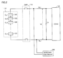
Fig. 2 is a diagram showing a detailed structure of a power storage device. -
Fig. 3 is a diagram for illustrating a current variation length. -
Fig. 4 is a diagram for illustrating a relationship between actual current variation length and command current variation length, and vehicle state. -
Fig. 5 is a time chart for illustrating an outline of control of detection of CID activation in a first embodiment. -
Fig. 6 is a functional block diagram for illustrating the control of detection of CID activation executed by an ECU in the first embodiment. -
Fig. 7 is a flowchart for illustrating details of processing of the control of detection of CID activation executed by the ECU in the first embodiment. -
Fig. 8 is a flowchart for illustrating details of processing of the control of detection of CID activation executed by the ECU in a second embodiment. -
Fig. 9 is a flowchart for illustrating details of processing of the control of detection of CID activation executed by the ECU in a third embodiment. - Embodiments of the present invention will hereinafter be described in detail with reference to the drawings. In the drawings, identical or corresponding parts are denoted by identical numerals, and description thereof will not be repeated.
-
Fig. 1 is an overall block diagram of avehicle 100 including a power supply system according to the present embodiment. - Referring to
Fig. 1 ,vehicle 100 includes apower storage device 110, a systemmain relay SMR 115, aload device 190,auxiliary equipment 200, and an ECU (Electronic Control Unit) 300, which corresponds to a control device. -
Load device 190 includes aconverter 120,inverters motor generators power transmission gear 150, anengine 160, adriving wheel 170,voltage sensors -
Power storage device 110 is an electric power storing component configured to be chargeable and dischargeable.Power storage device 110 is configured to include a secondary battery such as a lithium ion battery, a nickel-metal hydride battery, or a lead-acid battery, or a power storage element such as an electric double layer capacitor, for example. -
Power storage device 110 is connected to aconverter 120 through a power line PL1 and a ground line NL1.Power storage device 110 also stores electric power generated bymotor generators Power storage device 110 has an output of about 200 V, for example. -
Power storage device 110 is provided with avoltage sensor 111 and acurrent sensor 112.Voltage sensor 111 detects a voltage ofpower storage device 110 and outputs a detected value VB toECU 300.Current sensor 112 detects a current that is input to or output frompower storage device 110, and outputs a detected value IB toECU 300. AlthoughFig. 1 shows the structure in whichcurrent sensor 112 is provided on power line PL1 connected to a positive electrode terminal ofpower storage device 110,current sensor 112 may be provided on ground line NL1 connected to a negative electrode terminal ofpower storage device 110. - A relay included in
SMR 115 is inserted into each of power line PL1 and ground line NL1, which connectpower storage device 110 andconverter 120.SMR 115 is controlled by a control signal SE1 fromECU 300, and switches between supply and interruption of electric power betweenpower storage device 110 andload device 190. - Capacitor C1 is connected between power line PL1 and ground line NL1. Capacitor C1 reduces voltage fluctuation between power line PL1 and ground line NL1. A
voltage sensor 180 detects a voltage VL across capacitor C1 and outputs a detected value toECU 300. -
Converter 120 includes switching elements Q1, Q2, diodes D1, D2, and a reactor L1. - Switching elements Q1 and Q2 are connected in series between power line PL2 and ground line NL1, with the direction from power line PL2 toward ground line NL1 being a forward direction. In the present embodiment, IGBTs (Insulated Gate Bipolar Transistors), power MOS (Metal Oxide Semiconductor) transistors, power bipolar transistors, or the like can be used as the switching elements.
- Anti-parallel diodes D1, D2 are connected with switching elements Q1, Q2, respectively. Reactor L1 is provided between a connection node of switching elements Q1 and Q2 and power line PL1.
- Switching elements Q1, Q2 are controlled by a control signal PWC from
ECU 300, and performs voltage conversion operations between power line PL1 and ground line NL1, and between power line PL2 and ground line NL1. -
Converter 120 is basically controlled such that switching elements Q1 and Q2 are turned on or off in a complementary and alternate manner within each switching period.Converter 120 boosts a DC voltage VL to a DC voltage VH at the time of a boosting operation. This boosting operation is performed by supplying electromagnetic energy accumulated in reactor L1 during an ON period of switching element Q2 to power line PL2, through switching element Q1 andantiparallel diode D 1. -
Converter 120 also steps down the DC voltage VH to the DC voltage VL at the time of a step-down operation. This step-down operation is performed by supplying electromagnetic energy accumulated in reactor L1 during an ON period of switching element Q1 to ground line NL1, through switching element Q2 and antiparallel diode D2. - A voltage conversion ratio (ratio between VH and VL) in each of these boosting operation and step-down operation is controlled by an ON period ratio (duty ratio) between switching elements Q1, Q2 in the above-described switching period. Where the boosting operation and the step-down operation are not necessary (that is, where VH = VL), the voltage conversion ratio can be set to 1.0 (duty ratio = 100%) by setting control signal PWC such that switching elements Q1 and Q2 are fixed on and off, respectively.
- A capacitor C2 is connected between power line PL2 and ground line NL1, which connect
converter 120 andinverters voltage sensor 185 detects a voltage VH on capacitor C2 and outputs a detected value toECU 300. -
Inverters converter 120 through power line PL2 and ground line NL1.Inverters ECU 300, and convert DC electric power output fromconverter 120 into AC electric power for drivingmotor generators - Each of
motor generators - An output torque of each of
motor generators power transmission gear 150 formed of a reduction gear, a power split device, etc., to adriving wheel 170, causingvehicle 100 to run. At the time of regenerative braking operation ofvehicle 100,motor generators driving wheel 170. The generated electric power is then converted byinverters power storage device 110. -
Auxiliary equipment 200 includes a DC/DC converter 210, anauxiliary load 220, and anauxiliary battery 230. - DC/
DC converter 210 is connected to power line PL1 and ground line NL1 in parallel withload device 190. DC/DC converter 210 steps down voltage of electric power generated bypower storage device 110 ormotor generators ECU 300, and supplies the lowered voltage of electric power toauxiliary load 220 andauxiliary battery 230 through power line PL3. - When DC/
DC converter 210 detects, during reception of control signal PWD fromECU 300, that an input voltage from power line PL1 and ground line NL1 has decreased to be equal to or lower than a prescribed voltage level, it outputs an undervoltage signal UV toECU 300. -
Auxiliary battery 230 is typically implemented by a lead battery.Auxiliary battery 230 supplies a power supply voltage to loads of a low-voltage system invehicle 100, such asauxiliary load 220,ECU 300, and the like. Moreover,auxiliary battery 230 is charged with electric power supplied from DC/DC converter 210.Auxiliary battery 230 has an output voltage lower than that ofpower storage device 110, for example, about 12 V. -
Auxiliary load 220 includes devices such as lamps, a wiper, a heater, an audio device, a navigation system, and the like. - Although not shown in
Fig. 1 ,ECU 300 includes a CPU (Central Processing Unit), a storage device, and an input/output buffer, and performs input of signals from various sensors and the like or output of control signals to various devices, and also controlsvehicle 100 and various devices. Such control can be performed not only by software processing, but also by processing by dedicated hardware (electronic circuit). -
ECU 300 receives detected values of a voltage VB and a current IB from a sensor (not shown) included inpower storage device 110.ECU 300 calculates a state of charge (hereinafter also referred to as the SOC (State of Charge)) ofpower storage device 110, based on voltage VB and current IB. - As will be described below referring to
Fig. 2 , althoughpower storage device 110 is configured to output a desired voltage by stacking a plurality of battery cells in series, voltage VB detected byvoltage sensor 111 is generally calculated based on a sum of voltages of individual battery cells, rather than a voltage acrosspower storage device 100. Therefore, even if a CID activates, the output of voltage VB does not necessarily become zero. - Furthermore,
ECU 300 receives requested power PR to be input to or output frompower storage device 110, of vehicle driving force set based on a user's operation of an accelerator pedal (not shown).ECU 300controls converter 120 andinverters - Although
Fig. 1 shows the structure in which a single control device is provided asECU 300, control devices may be provided separately for various functions or devices to be controlled, for example, a control device forload device 190 and a control device forpower storage device 110. -
Fig. 2 is a diagram showing a detailed structure ofpower storage device 110. Referring toFig. 2 ,power storage device 110 is configured to include a plurality of battery cells CL1 to CLn connected in series (hereinafter also collectively referred to as "CL"), and provides a desired output voltage depending on the number of the battery cells CL. Each of these battery cells CL is provided with a current interrupt device CID. - Where an internal pressure of a battery cell CL has exceeded a prescribed value due to gas generated from an electrolyte of the battery cell CL, the CID is activated by the internal pressure to physically interrupt the battery cell from the other battery cells. Therefore, activation of any of the CIDs of the battery cells CL stops the flow of current through
power storage device 110. - It is known that when current is interrupted by the activation of a CID, a differential voltage between a total voltage of the battery cells excluding the battery cell of which CID has activated and an input voltage VL to load
device 190 is applied to the activated CID. Therefore, withSMR 115 being in a conducting state, if voltage VL decreases due to a reduction in electric charge incapacitor C 1 caused by consumption of electric power byload device 190 orauxiliary equipment 200, for example, the voltage applied to the activated CID also increases accordingly. Since a gap formed by a portion interrupted by the CID is small, if the voltage applied to the CID exceeds a prescribed withstand voltage, a secondary failure may be invited, such as occurrence of a spark in the above-described gap, for example. It is therefore necessary to quickly detect activation of the CID. Generally, however, a battery cell CL may not have means for outputting activation of a CID. - Moreover, it has been shown through experiments and the like that activation of a CID causes voltage VL to fluctuate. This is because, due to interruption of charge/discharge between
load device 190 andpower storage device 110, the amount of charge stored in capacitor C1 fluctuates due to consumption of electric power or power generation byload device 190 and consumption of electric power byauxiliary equipment 200. - For example, where a CID activates at a high load, such as when
vehicle 100 is running and consumption of electric power is large, voltage VL decreases sharply, as compared to the case where the CID is not activated. Accordingly, at a high load, it is possible to detect whether a CID has activated or not by monitoring a degree of increase or decrease in voltage VL. Alternatively, it is possible to detect whether a CID has activated or not, by using voltage VH instead of voltage VL. - If
voltage sensors 180, 185 (these sensors will also be collectively referred to as "system voltage sensors", hereinafter) have failed in a vehicle having the structure as described above, voltages on low- and high-voltage sides ofconverter 120 cannot be recognized byECU 300, which preventsconverter 120 from performing proper voltage conversion operations. - In such a case, for example, gates of switching elements Q1, Q2 in
converter 120 may be interrupted to stop the voltage conversion operations to prohibit charging ofpower storage device 110, while discharging ofpower storage device 110 only may be permitted to cause the vehicle to continue to run. In this case, control using current IB that is input to or output frompower storage device 110, instead of the system voltage sensors, is often performed. - When a CID activates in such a state, current IB that is input to or output from
power storage device 110 becomes substantially zero. Current IB, however, may also become zero where, for example, there is no consumption of electric power byload device 190 andauxiliary equipment 200, or where electric power generated and electric power consumed bymotor generators - In view of this problem, in the first embodiment, a configuration for detecting activation of a CID where the system voltage sensors have a malfunction, based on an actual input/output current IB of power storage device 110 (hereinafter also referred to as "actual current IB") and requested current to be input to or output from power storage device 110 (hereinafter also referred to as "command current IR"), without using detected values of the system voltage sensors, will be described. Specifically, the presence or absence of activation of a CID is detected based on a "variation length" obtained by accumulating variations in magnitude of each of actual current IB and command current IR for each sampling period, during a prescribed period of time. In this way, it is possible to suppress erroneous detection of activation of a CID, and accurately detect activation of a CID.
- Here, referring to
Fig. 3 , an actual current variation length IBint and a command current variation length IRint will be described first. WithFig. 3 , description is made taking actual current variation length IBint as an example. - Referring to
Fig. 3 , a case where current IB that is input to or output frompower storage device 110 has varied as represented by line W10 inFig. 3 is considered.ECU 300 samples current IB that is input to or output from the power storage device in constant periods. A current value for each sampling is represented by each point on line W10, and current values at times t = i - 1 and t = i, for example, from the beginning of sampling are denoted as IB (i - 1) and IB (i), respectively. - Accordingly, an amount of current variation ΔIB (i) from time t = i - 1 to time t = i is expressed by the following equation (I):

- Here, assuming that k is the number of sampling times within a predetermined period of time T0, actual current variation length IBint (k) is expressed by the following equation (2):

- That is, actual current variation length IBint can be an index indicating how much actual current IB has varied in a vibratory manner within the prescribed period of time T0. Therefore, for example, even if an average value of actual currents IB during the period of time T0 is the same, the more the current varies in a vibratory manner during that period, the greater the value of actual current variation length IBint becomes.
- Next, a technique for determining activation of a CID using actual current variation length IBint and command current variation length IPint is described referring to
Fig. 4 . InFig. 4 , the horizontal axis represents command current variation length IRint, and the vertical axis represents actual current variation length IBint. - Referring to
Figs. 1 and4 , whenpower storage device 110 is in a normal state with a CID not activated, the values of command current IR and actual current IB are generally equal, taking into account a time delay such as a control delay. Hence, actual current variation length IBint and command current variation length IRint are plotted within a range of region A surrounded by the dotted line shown inFig. 4 . - Conversely, when a CID has activated, input/output of a current to/from
power storage device 110 is stopped, and therefore, although command current variation length IRint increases with time, actual current variation length IBint becomes substantially zero. - That is, activation of the CID can be determined by detecting that command current variation length IRint is equal to or greater than a threshold value α (α > 0), and actual current variation length IBint is in a range smaller than a threshold value β (0 ≤ β < α) (that is, range B in
Fig. 4 ), while taking into account a detection error ofcurrent sensor 112, a calculation error of command current IR, etc. -
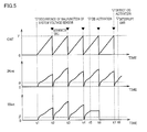
Fig. 5 is a time chart for illustrating an outline of control of detection of CID activation in the first embodiment. InFig. 5 , the horizontal axis represents time, and the vertical axis represents actual current variation length IBint (lower column), command current variation length IRint (middle column), and counter CNT (upper column) showing an accumulated time for each variation length. - Referring to
Fig. 5 , until time t1, at least one ofvoltage sensors - At time t1, where both of the system voltage sensors have a malfunction, the gates of switching elements Q1, Q2 in
converter 120 are interrupted, and at the same time, the accumulation process for actual current variation length IBint and command current variation length IRint is begun. - Since the gates of switching elements Q1, Q2 in
converter 120 are interrupted, and only discharging ofpower storage device 110 can be executed, both actual current IB and command current IR have positive values. - When counter CNT has then reached a threshold value γ showing a prescribed reference time (time t2) for determining activation of a CID, the values of command current variation length IRint and actual current variation length IBint at the time are compared with above-described threshold values α and β, respectively.
- At time t2, IRint > α and IBint > β, which is outside range B described with
Fig. 4 , and thus it is determined that a CID is not activated. Then, after completion of the determination, command current variation length IRint, actual current variation length IBint, and counter CNT are reset to initial values. - Similarly, at determination timings of times t3 and t4, it is determined that a CID is not activated, as was at time t2.
- Then, when a CID activates at time t5 while the accumulation process is being executed again from time t4, command current variation length IRint continues to increase with time. On the other hand, actual current variation length IBint is maintained at the same value from time t5 to the subsequent determination timing, time t6, because output of a current from
power storage device 110 is stopped by the activation of the CID. - In the example shown in
Fig. 5 , although the CID activates at the determination timing of time t6, command current variation length IRint and actual current variation length IBint are both greater than their threshold values. Therefore, activation of the CID is not detected yet at time t6. - However, after each of accumulated values is reset to the initial value at time t6, although command current variation length IRint increases with time, actual current variation length IBint is maintained at the initial value.
- Then, at the next determination timing, time t7, IRint > α and IBint < β, which is within range B shown in
Fig. 4 . Activation of the CID is thus determined. In response to this,SMR 115 is interrupted. -
Fig. 6 is a functional block diagram for illustrating the control of detection of CID activation executed byECU 300 in the first embodiment. Each of the functional blocks shown in the functional block diagram ofFig. 6 is implemented by hardware or software processing byECU 300. - Referring to
Fig 6 ,ECU 300 includes a current detectingunit 310, a command current calculatingunit 320, an accumulatingunit 330, a determiningunit 340, arelay control unit 350, and adrive control unit 360. - Current detecting
unit 310 receives actual current IB that is input to or output frompower storage device 110, which has been detected bycurrent sensor 112. Current detectingunit 310 calculates an amount of variation ΔIB in current IB from a current value detected in a previous sampling period. Current detectingunit 310 then outputs amount of variation ΔIB in actual current IB to accumulatingunit 330. - Command current calculating
unit 320 receives requested power PR to be input to or output frompower storage device 110 and voltage VB ofpower storage device 110 detected byvoltage sensor 111. Based on these items of information, command current calculatingunit 320 calculates command current IR to be input to or output frompower storage device 110. Specifically, command current IR is calculated in accordance with IR = PR/VB. - Command current calculating
unit 320 also calculates an amount of variation ΔIR from a command current calculated in the previous sampling period. Command current calculatingunit 320 then outputs amount of variation ΔIR in command current IR to accumulatingunit 330. - Accumulating
unit 330 receives amount of variation ΔIB in actual current IB from current detectingunit 310 and amount of variation ΔIR in command current from command current calculatingunit 320. Accumulatingunit 330 also receives control signal SE1 for drivingSMR 115 and a malfunction signal ABN indicating that the system voltage sensors have a malfunction. - Where
SMR 115 is placed in a conducting state by control signal SE1, and abnormal signal ABN is indicating that the system voltage sensors have a malfunction, accumulatingunit 330 accumulates amounts of variation ΔIB in actual current IB and amounts of variation ΔIR in command current IR for each sampling period, thereby calculating actual current variation length IBint and command current variation length IRint. Accumulatingunit 330 also accumulates counters CNT representing a time during which accumulation is executed (monitoring time). - Accumulating
unit 330 then outputs calculated actual current variation length IBint, command current variation length IRint, and counter CNT to determiningunit 340. When counter CNT has reached a count value corresponding to the predetermined reference time, and the output to determiningunit 340 has completed, accumulatingunit 330 resets the values of actual current variation length IBint, command current variation length IRint, and counter CNT to zero. - Determining
unit 340 receives actual current variation length IBint, command current variation length IRint, and counter CNT from accumulatingunit 330. Determiningunit 340 also receives an undervoltage signal UV from DC/DC converter 210. Based on these items of information, determiningunit 340 determines whether a CID has activated or not, in accordance with the technique as described withFigs. 4 and5 , and sets a determination flag FLG. For example, where it is determined that a CID has activated, determination flag FLG is set to ON, and where it is determined that a CID is not activated, the determination flag is set to OFF. Determiningunit 340 subsequently outputs set determination flag FLG to relaycontrol unit 350. -
Relay control unit 350 receives determination flag FLG from determiningunit 340. Where determination flag FLG is turned ON, i.e., a CID has activated,relay control unit 350 opensSMR 115 by control signal SE1. - Drive
control unit 360 receives requested power PR and malfunction signal ABN indicating that the system voltage sensors have a malfunction. Drivecontrol unit 360 generates control signals PWC, PWI for controllingconverters 120 andinverters drive control unit 360 causes the gates of switching elements Q1, Q2 inconverter 120 to be interrupted to prohibit the charging operation ofpower storage device 110 with generated electric power by way ofinverters power storage device 110 only. - Instead of interrupting the gates of switching elements Q1, Q2 in
converter 120, it is also possible to fix switching element Q1 only in an ON state. While this has the advantage of allowing regenerative operation, it also involves the risk of overcharging ofpower storage device 110, and therefore, it is preferred to interrupt the gates, from the standpoint of protectingpower storage device 110. -
Fig. 7 is a flowchart for illustrating details of processing of the control of detection of CID activation executed byECU 300 in the first embodiment. The processing of the flowchart shown in each ofFig. 7 and below-describedFigs. 8 and9 is implemented by invoking a program prestored inECU 300 from a main routine, and executing the program in prescribed periods. Alternatively, the processing in some steps can be implemented by dedicated hardware (electronic circuit). - Referring to
Figs. 1 and7 , in step ("step" is hereinafter abbreviated to "S") 100,ECU 300 determines whether both of the system voltage sensors (voltage sensors 180, 185) have a malfunction or not. - Where at least one of the system voltage sensors is in a normal state (NO in S100), the processing proceeds to S115, where
ECU 300 executes monitoring of CID activation based on the values of the system voltage sensors in a normal state, while causing the vehicle to run normally. - Where both of the system voltage sensors have a malfunction (YES in S100), the processing proceeds to S110, where
ECU 300 interrupts the gates of switching elements Q1, Q2 inconverter 120, and also causes regenerative operation to stop. -
ECU 300 then calculates command current IR based on requested power PR and voltage VB of power storage device 110 (S120), and also acquires actual current IB from current sensor 112 (S 130). - Subsequently in
S 140,ECU 300 starts counter CNT, and also calculates variation length IBint of actual current IB and variation length IRint of command current IR. - In S150,
ECU 300 determines whether a predetermined monitoring time has elapsed or not, based on a count value of counter CNT. - Where the predetermined monitoring time has not elapsed yet (NO in S150), the processing from
S 120 toS 140 is repeated to further count up the counter and continue the accumulation process for actual current variation length IBint and command current variation length IRint. - Where the prescribed monitoring time has elapsed (YES in S 150), the processing proceeds to
S 160, where it is determined whether or not command current variation length IRint is equal to or greater than the threshold value α, and whether or not actual current variation length IBint is smaller than the threshold value β, as described withFig. 4 . - Where command current variation length IRint is equal to or greater than the threshold value α, and actual current variation length IBint is smaller than the threshold value β (YES in S160), the processing proceeds to
S 170, whereECU 300 determines that a CID has activated. The processing subsequently proceeds toS 180, whereECU 300 opensSMR 115. - Conversely, where command current variation length IRint is smaller than the threshold value α, or actual current variation length IBint is equal to or greater than the threshold value β (NO in S160),
ECU 300 determines that the possibility that a CID has activated is low, and causes the processing to proceed toS 175, where it resets the accumulated values of counter CNT, command current variation length IRint, and actual current variation length IBint to the initial values, and returns the processing to the main routine. - Although not shown, similarly where it is determined that a CID has activated, the accumulated values of counter CNT, command current variation length IRint, and actual current variation length IBint are reset to the initial values.
- By performing the control in accordance with the foregoing processing, it is possible to correctly determine activation of a CID, even where the system voltage sensors have a malfunction.
- In the first embodiment, the configuration for detecting activation of a CID where the system voltage sensors have a malfunction, using the actual current variation length and the command current variation length, has been described.
- As described in the first embodiment, where the system voltage sensors have a malfunction, the gates of switching elements Q1, Q2 in
converter 120 inFig. 1 are interrupted, whereby capacitor C1 is charged only with the electric power supplied frompower storage device 110. - When a CID activates in such a state, electric power to be consumed by
motor generators auxiliary equipment 200 is supplied from the electric power stored in capacitor C1. Since the CID has activated, however, capacitor C1 is not charged bypower storage device 110, and consequently, the voltage across capacitor C1 (that is, voltage VL) gradually decreases. - Here, in the configuration shown in
Fig. 1 , since an input voltage of DC/DC converter 210 included inauxiliary equipment 200 decreases, DC/DC converter 210 cannot be activated if the voltage across capacitor C1 decreases below a prescribed voltage level, resulting in output of undervoltage signal UV from DC/DC converter 210. - Accordingly, in the second embodiment, the decrease in voltage VL is determined indirectly based on undervoltage signal UV from DC/
DC converter 210, whereby activation of a CID is detected. -
Fig. 8 is a flowchart for illustrating details of processing of the control of detection of CID activation executed byECU 300 in the second embodiment. - Referring to
Figs. 1 and8 , instep 200,ECU 300 determines whether or not both of the system voltage sensors have a malfunction. - Where at least one of the system voltage sensors is in a normal state (NO in S200), the processing proceeds to S250, where
ECU 300 executes monitoring of CID activation based on the values of the system voltage sensors in a normal state, while causing the vehicle to run normally. - Where both of the system voltage sensors have a malfunction (YES in S200), the processing proceeds to S210, where
ECU 300 interrupts the gates of switching elements Q1, Q2 inconverter 120, and also causes regenerative operation to stop. - Next,
ECU 300 determines in S220 whether or not undervoltage signal UV from DC/DC converter 210 is ON. - Where undervoltage signal UV is OFF (NO in S220),
ECU 300 determines that a CID is not activated, and returns the processing to the main routine. - Where undervoltage signal UV is ON (YES in S220), the processing proceeds to S230, where
ECU 300 determines that a CID has activated. The processing subsequently proceeds to S240, whereECU 300 opensSMR 115. - By performing the control in accordance with the foregoing processing, it is possible to correctly determine activation of a CID, even where the system voltage sensors have a malfunction.
- While the foregoing has described the configuration of detecting activation of a CID using undervoltage signal UV from DC/
DC converter 210, activation of a CID may also be detected based on a signal from a device different from DC/DC converter 210, so long as a signal similar to undervoltage signal UV can be output. Such a device includes, for example, an air-conditioning device (not shown) connected to power line PL1 and ground line NL1 in parallel withauxiliary equipment 200, and the devices described asauxiliary load 200. - The third embodiment shows an example of a case where the foregoing first and second embodiments are combined.
- The configuration according to the second embodiment does not require the calculation process for current variation lengths as in the first embodiment, thus achieving a simplified configuration as control logic. However, timing of detecting activation of a CID may be delayed because activation of a CID is not detected until voltage VL, which corresponds to the input voltage of DC/DC converter, decreases to a prescribed voltage level.
- The configuration according to the first embodiment, on the other hand, always requires the calculation process for current variation lengths regardless of the level of voltage VL, and thus has a relatively high calculation load. Therefore, where voltage VL has sharply decreased in a power running mode, detection of activation of a CID may be delayed due to the calculation of current variation lengths, or the CID activation detection performance may be degraded due to variation in the current sensor.
- Hence, by combining the first and second embodiments, where voltage VL has decreased to such an extent that undervoltage signal UV of the DC/DC converter is output, it is possible to determine activation of a CID immediately without performing the calculation process for current variation lengths, and also determine activation of a CID using the current variation lengths before voltage VL sufficiently decreases. In this way, activation of a CID can be quickly detected while reducing an unnecessary calculation process.
-
Fig. 9 is a flowchart for illustrating details of processing of the control of detection of CID activation executed byECU 300 in the third embodiment. The flowchart ofFig. 9 additionally includes step S111 in the flowchart described withFig. 7 in the first embodiment. Description of the same steps as those inFig. 7 is not repeated forFig. 9 . - Referring to
Figs. 1 and9 , where both of the system voltage sensors have a malfunction (YES in S100), and the gates ofconverter 120 are interrupted (S110),ECU 300 determines in S111 whether or not undervoltage signal UV from DC/DC converter 210 is ON. - Where undervoltage signal UV is OFF (NO in S111),
ECU 300 causes the processing to proceed to S120, where it executes detection of activation of a CID using actual current variation length IBint and command current variation length IRint, in accordance with the processing fromS 120 toS 160, as described in the first embodiment. - Conversely, where undervoltage signal UV is ON (YES in S111), the processing proceeds to
S 170, whereECU 300 determines that a CID has activated, without calculating actual current variation length IBint and command current variation length IRint. - By performing the control in accordance with the foregoing processing, it is possible to detect activation of a CID quickly while reducing an unnecessary calculation process.
- It is noted that "
SMR 115" in the present embodiment corresponds to one example of a "switching device" in the present invention. The "DC/DC converter" in the present embodiment corresponds to one example of a "voltage converting device" in the present invention. - It should be understood that the embodiments disclosed herein are illustrative and non-restrictive in every respect. The scope of the present invention is defined by the terms of the claims, rather than the description above, and is intended to include any modifications within the scope and meaning equivalent to the terms of the claims.
- 100: vehicle; 110: power storage device; 111, 180, 185: voltage sensor; 112: current sensor; 115: SMR; 120: converter; 130, 135: inverter; 140, 145: motor generator; 150: power transmission gear; 160: engine; 170: driving wheel; 190: load device; 200: auxiliary equipment; 210: DC/DC converter; 220: auxiliary load; 230: auxiliary battery; 300: ECU; 310: current detecting unit; 320: command current calculating unit; 330: accumulating unit; 340: determining unit; 350: relay control unit; 360: drive control unit; C1, C2: capacitor; CID: current interrupt device; CL, CL1 to CLn: battery cell; D1, D2: diode; L1: reactor; NL1: ground line; PL1 to PL3: power line; Q1, Q2: switching element.
Claims (14)
- A power supply system for supplying driving electric power to a load device (190), comprising:a power storage device (110) electrically connected to said load device (190); anda control device (300),said power storage device (110) including an interrupting device (CID) configured to activate where an internal pressure of said power storage device (110) has exceeded a prescribed value to interrupt a conduction path of said power storage device (110),said load device (190) including a voltage detecting unit (180, 185) for detecting a voltage applied to said load device (190), supply of electric power from said load device (190) to said power storage device (110) being stopped in response to a failure of said voltage detecting unit (180, 185), andsaid control device (300) detecting presence or absence of activation of said interrupting device (CID) based on information from a signal outputting unit (112, 210) different from said voltage detecting unit (180, 185).
- The power supply system according to claim 1, wherein
said signal outputting unit includes a current detecting unit (112) for detecting an actual current that is input to or output from said power storage device (110), and
said control device (300) detects presence or absence of activation of said interrupting device (CID) based on said actual current detected by said current detecting unit (112) and a command current to be input to or output from said power storage device (110) set in accordance with requested electric power based on a user's operation. - The power supply system according to claim 2, wherein
said control device (300) calculates a variation length obtained by accumulating a magnitude of an amount of variation for each sampling period for said actual current, and a variation length obtained by accumulating a magnitude of an amount of variation for each sampling period for said command current, during a prescribed period of time, and determines presence or absence of activation of said interrupting device (CID), based on the variation length of said actual current and the variation length of said command current. - The power supply system according to claim 3, wherein
said control device (300) uses a first threshold value and a second threshold value greater than said first threshold value, and determines that said interrupting device (CID) has activated when the variation length of said actual current is smaller than said first threshold value, and the variation length of said command current is greater than said second threshold value. - The power supply system according to claim 4, wherein
a switching device (115) is provided on a path connecting said power storage device (110) and said load device (190), for switching between a conducting state and a non-conducting state between said power storage device (110) and said load device (190), and
said control device (300) switches said switching device (115) into the non-conducting state where it determines that said interrupting device (CID) has activated. - The power supply system according to claim 1 or 2, wherein
said signal outputting unit includes auxiliary equipment (200) connected to said power storage device (110) in parallel with said load device (190),
said auxiliary equipment (200) has a device (210) capable of outputting a voltage decrease signal indicating that an input voltage has decreased while driving is being requested, and
said control device (300) detects presence or absence of activation of said interrupting device (CID) based on said voltage decrease signal from said device (210). - The power supply system according to claim 6, wherein
said device includes a voltage converting device (210) configured to step down voltage of electric power from said power storage device (110). - The power supply system according to claim 6, wherein
a switching device (115) is provided on a path connecting said power storage device (110) and said load device (190), for switching between a conducting state and a non-conducting state between said power storage device (110) and said load device (190), and
said control device (300) switches said switching device (115) into the non-conducting state where it determines that said interrupting device (CID) has activated. - A vehicle comprising:a power storage device (110);a load device (190) including a drive unit configured to generate driving force for said vehicle (100) using electric power from said power storage device (110); anda control device (300),said power storage device (110) including an interrupting device (CID) configured to activate where an internal pressure of said power storage device (110) has exceeded a prescribed value to interrupt a conduction path of said power storage device (110),said load device (190) including a voltage detecting unit (180, 185) for detecting a voltage applied to said load device (190), supply of electric power from said load device (190) to said power storage device (110) being stopped in response to a failure of said voltage detecting unit (180, 185), andsaid control device (300) detecting presence or absence of activation of said interrupting device (CID) based on information from a signal outputting unit (112, 210) different from said voltage detecting unit (180, 185).
- The vehicle according to claim 9, wherein
said signal outputting unit includes a current detecting unit (112) for detecting an actual current that is input to or output from said power storage device (110), and
said control device (300) calculates a variation length obtained by accumulating a magnitude of an amount of variation for each sampling period for said actual current detected by said current detecting unit (112), and a variation length obtained by accumulating a magnitude of an amount of variation for each sampling period for a command current to be input to or output from said power storage device (110) set in accordance with requested electric power based on a user's operation, during a prescribed period of time, and determines presence or absence of activation of said interrupting device (CID), based on the variation length of said actual current and the variation length of said command current. - The vehicle according to claim 9 or 10, wherein
said signal outputting unit includes auxiliary equipment (200) connected to said power storage device (110) in parallel with said load device (190),
said auxiliary equipment (200) has a voltage converting device (210) capable of stepping down voltage of electric power from said power storage device (110), and outputting a voltage decrease signal indicating that an input voltage has decreased while driving is being requested, and
said control device (300) detects presence or absence of activation of said interrupting device (CID) based on said voltage decrease signal from said voltage converting device (210). - A method for controlling a power supply system including a power storage device (110) for supplying driving electric power to a load device (190),
said power storage device (110) including an interrupting device (CID) configured to activate where an internal prcssure of said power storage device (110) has exceeded a prescribed value to interrupt a conduction path of said power storage device (110), and
said load device (190) including a voltage detecting unit (180, 185) for detecting a voltage applied to said load device (190),
said method comprising the steps of:detecting a failure of said voltage detecting unit (180, 185);stopping supply of electric power from said load device (190) to said power storage device (110) in response to the failure of said voltage detecting unit (180, 185); anddetecting presence or absence of activation of said interrupting device (CID) based on information from a signal outputting unit (112, 210) different from said voltage detecting unit (180, 185). - The method for controlling the power supply system according to claim 12, wherein
said signal outputting unit includes a current detecting unit (112) for detecting an actual current that is input to or output from said power storage device (110), and
the step of detecting presence or absence of activation of said interrupting device (CID) includes the steps of:calculating a variation length obtained by accumulating a magnitude of an amount of variation for each sampling period for said actual current detected by said current detecting unit (112), during a prescribed period of time;calculating a variation length obtained by accumulating a magnitude of an amount of variation for each sampling period for a command current to be input to and output from said power storage device (110) set in accordance with requested electric power based on a user's operation, during said prescribed period of time; anddetermining presence or absence of activation of said interrupting device (CID) based on the variation length of said actual current and the variation length of said command current. - The method for controlling the power supply system according to claim 12 or 13, wherein
said signal outputting unit includes auxiliary equipment (200) connected to said power storage device (110) in parallel with said load device (190),
said auxiliary equipment (200) includes a voltage converting device (210) capable of stepping down voltage of electric power from said power storage device (110), and outputting a voltage decrease signal indicating that an input voltage has decreased while driving is being requested, and
said step of detecting presence or absence of activation of said interrupting device (CID) includes detecting presence or absence of activation of said interrupting device (CID) based on said voltage decrease signal from said voltage converting device (210).
Applications Claiming Priority (1)
| Application Number | Priority Date | Filing Date | Title |
|---|---|---|---|
| PCT/JP2011/057779 WO2012131894A1 (en) | 2011-03-29 | 2011-03-29 | Power supply system, vehicle mounted therewith, and method of controlling power supply system |
Publications (2)
| Publication Number | Publication Date |
|---|---|
| EP2693592A1 true EP2693592A1 (en) | 2014-02-05 |
| EP2693592A4 EP2693592A4 (en) | 2015-11-11 |
Family
ID=46929727
Family Applications (1)
| Application Number | Title | Priority Date | Filing Date |
|---|---|---|---|
| EP11862061.6A Withdrawn EP2693592A4 (en) | 2011-03-29 | 2011-03-29 | POWER SUPPLY SYSTEM, VEHICLE EQUIPPED WITH SAME, AND METHOD FOR CONTROLLING AN ELECTRIC POWER SUPPLY SYSTEM |
Country Status (5)
| Country | Link |
|---|---|
| US (1) | US9190831B2 (en) |
| EP (1) | EP2693592A4 (en) |
| JP (1) | JP5621915B2 (en) |
| CN (1) | CN103444043B (en) |
| WO (1) | WO2012131894A1 (en) |
Cited By (3)
| Publication number | Priority date | Publication date | Assignee | Title |
|---|---|---|---|---|
| CN107878207A (en) * | 2016-09-29 | 2018-04-06 | 奥迪股份公司 | Motor vehicle and the method for running motor vehicle |
| CN113646648A (en) * | 2019-10-02 | 2021-11-12 | 株式会社Lg新能源 | Method and system for detecting connection failure of parallel battery units |
| EP3936879A4 (en) * | 2019-10-02 | 2022-06-08 | LG Energy Solution, Ltd. | METHOD AND SYSTEM FOR DETECTING FAILURE OF MOUNTING OF CELLS MOUNTED IN PARALLEL |
Families Citing this family (19)
| Publication number | Priority date | Publication date | Assignee | Title |
|---|---|---|---|---|
| WO2012086057A1 (en) * | 2010-12-24 | 2012-06-28 | トヨタ自動車株式会社 | Power supply system, vehicle mounted therewith, and method of controlling power storage apparatus |
| JP5673629B2 (en) * | 2012-08-29 | 2015-02-18 | 株式会社豊田自動織機 | LC filter protection device |
| CN104833933B (en) * | 2014-08-29 | 2017-11-03 | 北汽福田汽车股份有限公司 | The method for diagnosing faults of electrokinetic cell voltage sensor |
| US9751427B2 (en) * | 2014-09-03 | 2017-09-05 | Ford Global Technologies, Llc | Vehicle traction battery thermal conditioning |
| CN109311396B (en) * | 2016-06-14 | 2022-05-13 | 沃尔沃卡车集团 | Method and apparatus for controlling operation of an energy storage system in a vehicle |
| WO2019035169A1 (en) * | 2017-08-14 | 2019-02-21 | 日産自動車株式会社 | Power supply system and control method thereof |
| JP6554151B2 (en) | 2017-08-31 | 2019-07-31 | 本田技研工業株式会社 | Vehicle power system |
| US12059962B2 (en) * | 2018-09-18 | 2024-08-13 | Gs Yuasa International Ltd. | Control method for mobile power supply system, and power supply system for moving body |
| US11642965B2 (en) | 2018-10-11 | 2023-05-09 | Keith Johnson | System and method of powering an external device with a vehicular battery system |
| US11130405B2 (en) * | 2018-10-11 | 2021-09-28 | Keith Johnson | System and method of powering an external device with a vehicular battery system |
| KR102576684B1 (en) * | 2018-11-15 | 2023-09-11 | 에스케이하이닉스 주식회사 | Storage device and operating method thereof |
| JP7252807B2 (en) * | 2019-03-27 | 2023-04-05 | 株式会社Subaru | power system |
| US12191722B2 (en) * | 2019-05-31 | 2025-01-07 | MagniX USA, Inc. | High-torque electric motor assembly |
| WO2021033480A1 (en) * | 2019-08-22 | 2021-02-25 | パナソニックIpマネジメント株式会社 | Management device and power storage system |
| JP2021058058A (en) * | 2019-10-02 | 2021-04-08 | 株式会社ケーヒン | Power conversion device |
| CN110635534B (en) * | 2019-10-10 | 2021-02-23 | 国网江苏综合能源服务有限公司 | Self-diagnosis off-grid current limiting control method for mobile electrochemical energy storage system |
| CN113525106B (en) * | 2020-04-13 | 2023-11-17 | 广州汽车集团股份有限公司 | DC/DC converter and control method thereof |
| JP7256480B2 (en) * | 2020-05-13 | 2023-04-12 | トヨタ自動車株式会社 | Power supply circuit control device and power supply circuit control program |
| CN114362629B (en) * | 2021-12-30 | 2023-08-29 | 上海电机学院 | Cage type asynchronous motor energy-saving control system |
Family Cites Families (13)
| Publication number | Priority date | Publication date | Assignee | Title |
|---|---|---|---|---|
| US6917179B2 (en) * | 2001-10-25 | 2005-07-12 | Toyota Jidosha Kabushiki Kaisha | Load driver and control method for safely driving DC load and computer-readable recording medium with program recorded thereon for allowing computer to execute the control |
| JP4840154B2 (en) * | 2007-01-23 | 2011-12-21 | パナソニック株式会社 | Power supply equipment |
| JP2008234903A (en) * | 2007-03-19 | 2008-10-02 | Gs Yuasa Corporation:Kk | Battery and battery system |
| JP4288333B1 (en) | 2007-12-18 | 2009-07-01 | トヨタ自動車株式会社 | Vehicle power supply |
| JP2009171644A (en) * | 2008-01-10 | 2009-07-30 | Toyota Motor Corp | Vehicle power supply apparatus and control method thereof |
| JP2009189209A (en) | 2008-02-08 | 2009-08-20 | Toyota Motor Corp | Vehicle power supply apparatus and control method thereof |
| JP5015858B2 (en) * | 2008-05-12 | 2012-08-29 | トヨタ自動車株式会社 | Electric vehicle power supply system and control method thereof |
| JP2010051072A (en) | 2008-08-20 | 2010-03-04 | Toyota Motor Corp | Abnormality monitoring device of power supply system and abnormality monitoring method of power supply system |
| KR101124973B1 (en) * | 2009-12-03 | 2012-03-27 | 현대자동차주식회사 | Motor control system for hybrid vehicle and method for controlling the same |
| JP2011130551A (en) * | 2009-12-16 | 2011-06-30 | Sanyo Electric Co Ltd | Power supply device and vehicle with the same |
| JP2011135657A (en) * | 2009-12-22 | 2011-07-07 | Sanyo Electric Co Ltd | Battery system and vehicle with the same, and method for detecting current limit state of the battery system |
| WO2012086057A1 (en) * | 2010-12-24 | 2012-06-28 | トヨタ自動車株式会社 | Power supply system, vehicle mounted therewith, and method of controlling power storage apparatus |
| US9196930B2 (en) * | 2011-03-24 | 2015-11-24 | Ford Global Technologies, Llc | Vehicle battery cell with integral control circuit |
-
2011
- 2011-03-29 CN CN201180069597.XA patent/CN103444043B/en active Active
- 2011-03-29 JP JP2013506912A patent/JP5621915B2/en active Active
- 2011-03-29 US US14/007,417 patent/US9190831B2/en active Active
- 2011-03-29 WO PCT/JP2011/057779 patent/WO2012131894A1/en not_active Ceased
- 2011-03-29 EP EP11862061.6A patent/EP2693592A4/en not_active Withdrawn
Cited By (8)
| Publication number | Priority date | Publication date | Assignee | Title |
|---|---|---|---|---|
| CN107878207A (en) * | 2016-09-29 | 2018-04-06 | 奥迪股份公司 | Motor vehicle and the method for running motor vehicle |
| EP3308997A1 (en) * | 2016-09-29 | 2018-04-18 | Audi Ag | Motor vehicle and method for operating a motor vehicle |
| CN113646648A (en) * | 2019-10-02 | 2021-11-12 | 株式会社Lg新能源 | Method and system for detecting connection failure of parallel battery units |
| EP3936879A4 (en) * | 2019-10-02 | 2022-06-08 | LG Energy Solution, Ltd. | METHOD AND SYSTEM FOR DETECTING FAILURE OF MOUNTING OF CELLS MOUNTED IN PARALLEL |
| EP3951411A4 (en) * | 2019-10-02 | 2022-06-08 | LG Energy Solution, Ltd. | PARALLEL CONNECTION CELL CONNECTION FAULT DETECTION METHOD AND SYSTEM |
| CN113646648B (en) * | 2019-10-02 | 2024-04-02 | 株式会社Lg新能源 | Method and system for detecting connection failure of parallel battery units |
| US11959971B2 (en) | 2019-10-02 | 2024-04-16 | Lg Energy Solution, Ltd. | Method and system for detecting connection fault of parallel connection cell |
| US12211978B2 (en) | 2019-10-02 | 2025-01-28 | Lg Energy Solution, Ltd. | Method and system for detecting connection fault of parallel connection cells |
Also Published As
| Publication number | Publication date |
|---|---|
| CN103444043A (en) | 2013-12-11 |
| US9190831B2 (en) | 2015-11-17 |
| CN103444043B (en) | 2015-08-05 |
| US20140022681A1 (en) | 2014-01-23 |
| JPWO2012131894A1 (en) | 2014-07-24 |
| JP5621915B2 (en) | 2014-11-12 |
| WO2012131894A1 (en) | 2012-10-04 |
| EP2693592A4 (en) | 2015-11-11 |
Similar Documents
| Publication | Publication Date | Title |
|---|---|---|
| EP2693592A1 (en) | Power supply system, vehicle mounted therewith, and method of controlling power supply system | |
| US10011184B2 (en) | Power supply system for vehicle | |
| US8924059B2 (en) | Electronic control device and vehicle control system | |
| CN103546089B (en) | Accumulating system and processing method | |
| US20150097501A1 (en) | Electric vehicle power conversion system | |
| US20140103883A1 (en) | Power supply device of vehicle | |
| CN109941106A (en) | The power-supply system of electric vehicle | |
| JP2017229132A (en) | Power supply unit for vehicle and power supply controller | |
| EP2378304A2 (en) | Apparatus for and method of calculating state of charge, and electric system | |
| US20160276823A1 (en) | Power supply system | |
| JP5556902B2 (en) | Power supply system, vehicle equipped with the same, and method for controlling power storage device | |
| JP5699930B2 (en) | Power supply system, vehicle equipped with the same, and control method of power supply system | |
| CN110239565A (en) | The control method of electric vehicle and electric vehicle | |
| US9106091B2 (en) | Vehicle and vehicle control method | |
| JP6701976B2 (en) | Electric vehicle | |
| US12319153B2 (en) | Electrified vehicle | |
| JP5659943B2 (en) | Power supply system, vehicle equipped with the same, and vehicle control method | |
| JP7421524B2 (en) | Storage battery control device, power storage system, and storage battery control method | |
| JP2016067077A (en) | Electric power storage system | |
| CN110091715A (en) | Electric vehicle and control method for electric vehicle | |
| JP2014204627A (en) | Power conversion device | |
| JP7736918B2 (en) | Power Supply Control Device | |
| US20250368074A1 (en) | Solar charging system | |
| JP2025059627A (en) | Relay diagnostic device and method | |
| EP3651309A1 (en) | Power supply for vehicle and control method of power supply |
Legal Events
| Date | Code | Title | Description |
|---|---|---|---|
| PUAI | Public reference made under article 153(3) epc to a published international application that has entered the european phase |
Free format text: ORIGINAL CODE: 0009012 |
|
| 17P | Request for examination filed |
Effective date: 20130930 |
|
| AK | Designated contracting states |
Kind code of ref document: A1 Designated state(s): AL AT BE BG CH CY CZ DE DK EE ES FI FR GB GR HR HU IE IS IT LI LT LU LV MC MK MT NL NO PL PT RO RS SE SI SK SM TR |
|
| DAX | Request for extension of the european patent (deleted) | ||
| RA4 | Supplementary search report drawn up and despatched (corrected) |
Effective date: 20151008 |
|
| RIC1 | Information provided on ipc code assigned before grant |
Ipc: B60L 3/04 20060101ALI20151002BHEP Ipc: B60L 11/12 20060101ALI20151002BHEP Ipc: B60L 7/14 20060101ALI20151002BHEP Ipc: H02H 3/28 20060101ALI20151002BHEP Ipc: B60L 1/00 20060101ALI20151002BHEP Ipc: B60L 11/18 20060101ALI20151002BHEP Ipc: H02J 7/00 20060101AFI20151002BHEP Ipc: B60L 15/00 20060101ALI20151002BHEP |
|
| STAA | Information on the status of an ep patent application or granted ep patent |
Free format text: STATUS: THE APPLICATION IS DEEMED TO BE WITHDRAWN |
|
| 18D | Application deemed to be withdrawn |
Effective date: 20160507 |