EP2693561A1 - Antenna device - Google Patents
Antenna device Download PDFInfo
- Publication number
- EP2693561A1 EP2693561A1 EP13178457.1A EP13178457A EP2693561A1 EP 2693561 A1 EP2693561 A1 EP 2693561A1 EP 13178457 A EP13178457 A EP 13178457A EP 2693561 A1 EP2693561 A1 EP 2693561A1
- Authority
- EP
- European Patent Office
- Prior art keywords
- arm
- arms
- leg
- thickness
- legs
- Prior art date
- Legal status (The legal status is an assumption and is not a legal conclusion. Google has not performed a legal analysis and makes no representation as to the accuracy of the status listed.)
- Granted
Links
Images

Classifications
-
- H—ELECTRICITY
- H01—ELECTRIC ELEMENTS
- H01Q—ANTENNAS, i.e. RADIO AERIALS
- H01Q1/00—Details of, or arrangements associated with, antennas
- H01Q1/27—Adaptation for use in or on movable bodies
- H01Q1/32—Adaptation for use in or on road or rail vehicles
-
- H—ELECTRICITY
- H01—ELECTRIC ELEMENTS
- H01Q—ANTENNAS, i.e. RADIO AERIALS
- H01Q1/00—Details of, or arrangements associated with, antennas
- H01Q1/005—Damping of vibrations; Means for reducing wind-induced forces
-
- H—ELECTRICITY
- H01—ELECTRIC ELEMENTS
- H01Q—ANTENNAS, i.e. RADIO AERIALS
- H01Q1/00—Details of, or arrangements associated with, antennas
- H01Q1/27—Adaptation for use in or on movable bodies
- H01Q1/32—Adaptation for use in or on road or rail vehicles
- H01Q1/3208—Adaptation for use in or on road or rail vehicles characterised by the application wherein the antenna is used
- H01Q1/3233—Adaptation for use in or on road or rail vehicles characterised by the application wherein the antenna is used particular used as part of a sensor or in a security system, e.g. for automotive radar, navigation systems
- H01Q1/3241—Adaptation for use in or on road or rail vehicles characterised by the application wherein the antenna is used particular used as part of a sensor or in a security system, e.g. for automotive radar, navigation systems particular used in keyless entry systems
Definitions
- the present invention relates to an antenna device.
- a vehicle may include an electronic key system that verifies a wireless signal transmitted from an electronic key to control the locking and unlocking of the vehicle doors and the starting of a drive source.
- An antenna device that receives wireless signals is arranged in such a vehicle that includes the electronic key system.
- Japanese Laid-Open Patent Publication No. 2012-29137 describes a reverse-L-shaped antenna fixed to a substrate.
- the reverse-L-shaped antenna includes a plate-like leg, which extends orthogonal to the upper surface of the substrate, and a plate-like arm, which is continuous with a distal portion of the leg and which extends parallel to the upper surface of the substrate.
- the antenna device is often installed in a vehicle door.
- the vehicle door vibrates when the vehicle travels and when the door opens and closes.
- the vibration is transmitted from the leg to the arm in the antenna.
- the conventional antenna (arm) is formed to have a uniform thickness in one thickness-wise direction.
- a plate-like antenna 51 is cantilevered by a substrate 52.
- the antenna 51 has a tendency to vibrate in the thickness-wise direction.
- vibration of the vehicle door may cause resonance at the arm of the antenna 51. Consequently, vibrational noise resulting from the resonance of the antenna 51 may be audible to a vehicle occupant.
- One embodiment of the present invention is an antenna device including an antenna.
- the antenna includes a plurality of plate-like legs, coupled to a base plate, and a plurality of plate-like arms, supported by the legs. Adjacent ones of the arms are continuous with each other. At least two of the legs have thicknesses in different thickness-wise directions.
- an antenna that resists resonance is provided.
- an antenna device 1 is installed in, for example, a vehicle (vehicle door).
- the antenna device 1 includes a substrate 2, which serves as a base plate, and an antenna 3 (antenna element), which is coupled to an upper surface of the substrate 2.
- the antenna 3 receives a wireless signal transmitted from a vehicle electronic key (not illustrated) and sends the received signal to an electronic circuit (not illustrated) in the substrate 2.
- the antenna 3 is formed by punching out a metal piece having a predetermined pattern from a sheet of metal plate and then bending the metal piece.
- the antenna 3 includes a plurality of (three in the present example) legs 11 to 13, extending orthogonal to the substrate 2, and a frame-shaped arm portion 20, supported by the legs 11 to 13.
- the arm portion 20 includes a plurality of (four in the present example) arms 21 to 24.
- the legs 11 to 13 and the arms 21 to 24 are plate-like and have a uniform thickness.
- the leg 11 extends in the upward direction from the upper surface of the substrate 2.
- the leg 11 has a thickness in a first direction (front-to-rear direction in Fig. 1 ) that is parallel to the substrate 2. That is, the thickness-wise direction of the leg 11 is set in the first direction.
- the leg 11 has a distal portion on which the arm 21 is arranged.
- the arm 21 extends in a second direction (left-to-right direction in Fig. 1 ) that is parallel to the substrate 2 and perpendicular to the first direction. Accordingly, the arm 21 is perpendicular to the leg 11.
- the arm 21 has a thickness in the first direction. That is, the thickness-wise direction of the arm 21 is set in the first direction.
- the arm 21 and the leg 11 include continuous front surfaces and continuous rear surfaces.
- the leg 11 and the arm 21 are T-shaped as a whole.
- the arm 21 includes a right end 21a and a left end 21b as illustrated in Fig. 1 .
- the arm 22 is arranged on the right end 21a of the arm 21.
- the arm 22 extends in the first direction (front-to-rear direction) from the right end 21a of the arm 21.
- the arm 22 is continuous with the upper end surface of the arm 21 and extends in the rear direction from the right end 21a of the arm 21. Accordingly, the arm 21 and the arm 22 are perpendicular to each other.
- the arm 22 has a thickness in a third direction (vertical direction, or up-to-down direction in Fig. 1 ). That is, the thickness-wise direction of arm 22 is set in the third direction. As illustrated in Fig.
- the arm 22 and the arm 21 include continuous right end surfaces.
- the arm 22 includes a front end 22b, which is continuous with the arm 21, and an opposite rear end 22a.
- the leg 12 has a thickness in the second direction (left-to-right direction). That is, the thickness-wise direction of the leg 12 is set in the second direction.
- the leg 12 includes a left surface that is continuous with a left end surface of the arm 22.
- the leg 12 and the arm 22 are T-shaped as a whole.
- the arm 23 extends in the second direction (left-to-right direction) from the rear end 22a of the arm 22.
- the arm 23 is continuous with an upper surface of the arm 22 and extends in the left direction from the rear end 22a of the arm 22. Accordingly, the arm 22 and the arm 23 are perpendicular to each other.
- the arm 23 has a thickness in the first direction (front-to-rear direction). That is, the thickness-wise direction of the arm 23 is set in the first direction.
- the arm 23 includes a right end 23b, which is continuous with the arm 22, and an opposite left end 23a.
- the arm 23 and the leg 13 are perpendicular to each other.
- the leg 13 has a thickness in the first direction (front-to-rear direction). That is, the thickness-wise direction of the leg 13 is set in the first direction.
- the arm 23 and the leg 13 include continuous front surfaces and continuous rear surfaces.
- the leg 13 and the arm 23 are T-shaped as a whole.
- the arm 24 extends from the left end 23a of the arm 23 in the first direction (front-to-rear direction).
- the arm 24 is continuous with the upper end surface of the arm 23 and extends in the front direction from the left end 23a of the arm 23. Accordingly, the arm 24 and the arm 23 are perpendicular to each other.
- the arm 24 has a thickness in the third direction (up-to-down direction). That is, the thickness-wise direction of the arm 24 is set in the third direction.
- the arm 24 includes a rear end 24b, which is continuous with the arm 23, and an opposite front end 24a.
- the front end 24a of the arm 24 includes an upper surface that is continuous with the upper end surface of the left end 21b of the arm 21.
- the arm 24 and the arm 21 are perpendicular to each other.
- the arm 21 and the arm 23 both support the arm 24.
- the arm 24 includes a left end surface that is continuous with a left end surface of the arm 21 and a left end surface of the arm 23.
- the leg 11 includes a left end surface separated by distance d1 from the right end surface (inner end surface) of the arm 24. Further, the leg 13 includes a left end surface separated by distance d2 from the right end surface of the arm 24. The distances d1 and d2 are set as coprime values.
- a vibrational wave generated by the vibration of the substrate 2 is transmitted to the legs 11 to 13.
- a plate member having a thickness-wise direction that is the same as the vibrational direction vibrates greatly and easily transmits vibrational waves
- a plate member having a thickness-wise direction that differs from the vibrational direction vibrates slightly and subtly transmits vibrational waves. Accordingly, when two plate members having different thickness-wise directions are perpendicular to each other, the transmission of vibrational waves from one plate member to the other plate member is suppressed.
- the thickness-wise direction of the leg 12 is set in the second direction (left-to-right direction) that differs from the vibrational direction of the substrate 2 (here, the first direction).
- the leg 12 resists the transmission of vibrational waves.
- the thickness-wise direction of the arm 22, which is continuous with the leg 12 is set in the third direction (up-to-down direction) that differs from the vibrational direction of the substrate 2. Accordingly, the arm 22 also resists the transmission of vibrational waves. This suppresses resonance of the leg 12 and the arm 22.
- the thickness-wise direction of each of the legs 11 and 13 is set in the first direction (front-to-rear direction) that is the same as the vibrational direction of the substrate 2 (here, the first direction). Accordingly, the legs 11 and 13 easily transmit vibrational waves.
- the arm 21, which is continuous with the leg 11, and the arm 23, which is continuous with the leg 13, easily transmit vibrational waves.
- the arms 21 and 23 are perpendicular to the arm 22 at the right ends 21a and 23b, and the thickness-wise direction of each of the arms 21 and 23 (first direction) differs from the thickness-wise direction of the arm 22 (third direction). Accordingly, vibrational waves are subtly transmitted from the arms 21 and 23 to the arm 22, and resonance of the arm 22 is suppressed. Further, resonance of the arms 21 and 23 is also suppressed at the right side of the legs 11 and 13.
- the arms 21 and 23 are continuous with the arm 24 at the left ends 21b and 23a.
- the left end surface of the leg 11 is separated by distance d1 from the right end surface of the arm 24.
- the left end surface of the leg 13 is separated by distance d2 from the right end surface of the arm 24.
- the distances d1 and d2 are set as coprime values.
- the wavelength of the vibrational waves transmitted from the arm 21 to the arm 24 differs from the wavelength of the vibrational waves transmitted from the arm 23 to the arm 24. Accordingly, resonance is substantially not generated at the arm 24 where the vibrational waves having different wavelengths are transmitted. This suppresses resonance of the arms 21 and 23 at the left side of the legs 11 and 13.
- the thickness-wise direction of each of the legs 11 and 13 is set in the first direction (front-to-rear direction) that differs from the vibrational direction of the substrate 2 (here, the second direction).
- the legs 11 and 13 resist the transmission of vibrational waves.
- the thickness-wise direction of each of the arms 21 and 23, which are respectively continuous with the legs 11 and 13, is also set in the first direction (front-to-rear direction).
- the arms 21 and 23 resist the transmission of vibrational waves. Accordingly, vibrational waves are subtly transmitted from the legs 11 and 13 to the arms 21 and 23. As a result, resonance is suppressed at the legs 11 and 13 and the arms 21 and 23.
- the thickness direction of the leg 12 is set in the second direction (left-to-right direction), which is the same as the vibrational direction of the substrate 2 (here, the second direction). Accordingly, the leg 12 easily transmits vibrational waves.
- the thickness-wise direction of the arm 22, which is continuous with the leg 12 is set in the third direction (up-to-down direction) that differs from the vibrational direction of the substrate 2. Accordingly, the arm 22 resists the transmission of vibrational waves.
- the arm 22 is perpendicular to the arms 21 and 23 at the front end 22b and the rear end 22a, and the thickness-wise direction of the arm 22 (third direction) differs from the thickness-wise direction of each of the arms 21 and 23 (first direction). Accordingly, vibrational waves are subtly transmitted from the arm 22 to the arms 21 and 23, and resonance is suppressed at the arms 21 and 23. This suppresses resonance of the leg 12, which is continuous with the arm 22.
- the thickness-wise direction of the arm 24 is set in the third direction (up-to-down direction) that differs from the vibrational direction of the substrate 2 (here, the second direction). Accordingly, the arm 24 resists transmission of vibrational waves.
- the arm 24 is continuous with the arms 21 and 23 where resonance is suppressed. This suppresses resonance of the arm 24. In this manner, resonance of the antenna 3 is suppressed, and the generation of vibrational noise that would be caused by the resonance is suppressed.
- the thickness-wise direction of each of the legs 11 and 13 is set in the first direction (front-to-rear direction) that differs from the vibrational direction of the substrate 2 (here, the third direction).
- the legs 11 and 13 resist the transmission of vibrational waves.
- the thickness-wise direction of each of the arms 21 and 23, which are respectively continuous with the legs 11 and 13, is also set in the first direction (front-to-rear direction).
- the arms 21 and 23 also resist the transmission of vibrational waves. Accordingly, vibrational waves are subtly transmitted from the legs 11 and 13 to the arms 21 and 23. As a result, resonance is suppressed at the legs 11 and 13 and the arms 21 and 23.
- the thickness direction of the leg 12 is set in the second direction (left-to-right direction), which differs from the vibrational direction of the substrate 2 (here, the third direction). Accordingly, the leg 12 resists the transmission of vibrational waves.
- the thickness-wise direction of the arm 22, which is continuous with the leg 12 is set in the third direction (up-to-down direction), which is the same as the vibrational direction of the substrate 2. Accordingly, the arm 22 easily transmits vibrational waves.
- the arm 22 is continuous with the arms 21 and 23, which subtly transmit the vibrational waves, at the front end 22b and the rear end 22a. This suppresses resonance of the arm 22.
- the thickness-wise direction of the arm 24 is set in the third direction (up-to-down direction), which is the same as the vibrational direction of the substrate 2 (here, the third direction). Accordingly, the arm 24 easily transmits vibrational waves.
- the arm 24 is perpendicular to the arms 21 and 23 at the front end 24a and the rear end 24b.
- the thickness-wise direction of each of the arms 21 and 23 is set in the first direction. This suppresses resonance of the arms 21 and 23. Thus, resonance is also suppressed at the arm 24, which is continuous with the arms 21 and 23. Further, as illustrated in Figs.
- the left end surface of the leg 11 is separated by distance d1 from the right end surface of the arm 24, and the left end surface of the leg 13 is separated by distance d2 from the right end surface of the arm 24.
- the distances d1 and d2 are set as coprime values.
- the wavelength of the vibrational waves transmitted from the arm 21 to the arm 24 differs from the wavelength of the vibrational waves transmitted from the arm 23 to the arm 24. Accordingly, resonance is substantially not generated at the arm 24 where vibrational waves having difference wavelengths are transmitted. In this manner, resonance of the antenna 3 is suppressed, and the generation of vibrational noise that would be caused by the resonance is suppressed.
- the present embodiment has the advantages described below.
- the arm 24 may be omitted.
- the arm portion 20 is C-shaped or U-shaped as viewed from above.
- the leg 12 and the arm 22 may be omitted. That is, the arm portion 20 does not have to be frame-shaped.
- the arm 24 and the leg 11 may be omitted.
- the arm 24 and the leg 13 may be omitted.
- the leg 11 and the arms 21 and 24 may be omitted.
- the leg 13 and the arms 23 and 24 may be omitted.
- the arm portion 20 is L-shaped as viewed from above. In other words, the antenna 3 only needs to include two or more legs and two or more arms. Such a structure also obtains advantages (1) and (2).
- a leg extending in the upward direction from the upper surface of the substrate 2 may support the arm 24.
- the arm portion 20 is supported by four legs. That is, the arm portion 20 only needs to be supported by a plurality of legs having different thickness-wise directions.
- Such a structure also includes the same advantages as the above embodiment.
- an antenna 40 may include two legs 41 and 42, extending in the upward direction from the upper surface of a substrate (not illustrated), and two arms 43 and 44, respectively arranged on distal portions of the legs 41 and 42.
- the thickness-wise direction of the leg 41 is set in a first direction (for example, left-to-right direction).
- the thickness-wise direction of the leg 42 is set in the second direction (for example, front-to-rear direction) that differs from the first direction.
- the arm 43 extends in the first direction (left-to-right direction).
- the thickness-wise direction of the arm 43 is set in the third direction (for example, up-to-down direction) that differs from the first and second directions.
- the arm 44 extends in the first direction (left-to-right direction).
- the thickness-wise direction of the arm 44 is set in the second direction (front-to-rear direction).
- the arm 44 has a left end that is continuous with a right end of the arm 43.
- the leg 41 suppresses the transmission of vibrational waves.
- the leg 42 suppresses the transmission of vibrational waves.
- the arm 43 When vibration is produced in the front-to-rear direction and the left-to-right direction, the arm 43 suppresses the transmission of vibrational waves. When vibration is produced in the left-to-right direction and the up-to-down direction, the arm 44 suppresses the transmission of vibrational waves. In this manner, the antenna 40 includes legs and arms that suppress the transmission of vibrational waves regardless of the vibrational direction of the antenna 40. Thus, the antenna 40 resists resonance regardless of the direction of vibration. This suppresses the generation of vibrational noise caused by resonance of the antenna 40.
- the width of the arms 21 and 23 (i.e., length in the up-to-down direction) may be decreased to increase the distance from the upper surface of the substrate 2 to the lower end surfaces of the arms 21 and 23.
- the gain of the antenna 3 may be increased without changing the height of the antenna 3 from the upper surface of the substrate 2.
- each of the legs 11 to 13 and the arms 21 to 24 includes an end surface that is continuous with the end surface of the adjacent member (adjacent arm or leg).
- the adjacent member adjacent arm or leg
- two adjacent members only need to be continuous with each other, and the end surfaces of two adjacent members do not necessarily have to be continuous.
- each of the legs 11 to 13 and the arms 21 to 24 is set to be orthogonal or parallel to the upper surface of the substrate 2, but may be set in the other direction. That is, the legs 11 to 13 and the arms 21 to 24 only need to be arranged so that two adjacent members (adjacent arms, or adjacent arm and leg) have different thickness-wise directions.
- the legs 11 to 13 and the arms 21 to 24 are plate members having rectangular cross-sections but may be plate-like members having elliptic cross-sections. Even in such a case, each of the legs and arms also has a thickness-wise direction. Thus, the same advantages as the above embodiment are obtained.
- the antenna device 1 is arranged in a vehicle door but may be arranged at any location in the vehicle. Further, the antenna device 1 may be arranged in an apparatus other than a vehicle.
- the antenna devices 1 of the above embodiment and modifications may be used as any antenna device attached to any apparatus that may vibrate, such as a door of a building.
- An antenna device (1) includes an antenna (3).
- the antenna (3) includes a plurality of plate-like legs (11-13), coupled to a base plate (2), and a plurality of plate-like arms (21-23), supported by the legs (11-13). Adjacent ones of the arms are continuous with each other. At least two (11,12; 12,13) of the legs have thicknesses in different thickness-wise directions.
Landscapes
- Engineering & Computer Science (AREA)
- Computer Security & Cryptography (AREA)
- Radar, Positioning & Navigation (AREA)
- Remote Sensing (AREA)
- Support Of Aerials (AREA)
- Details Of Aerials (AREA)
Abstract
Description
- The present invention relates to an antenna device.
- A vehicle may include an electronic key system that verifies a wireless signal transmitted from an electronic key to control the locking and unlocking of the vehicle doors and the starting of a drive source. An antenna device that receives wireless signals is arranged in such a vehicle that includes the electronic key system. Japanese Laid-Open Patent Publication No.
2012-29137 - The antenna device is often installed in a vehicle door. The vehicle door vibrates when the vehicle travels and when the door opens and closes. The vibration is transmitted from the leg to the arm in the antenna. As described in the publication, the conventional antenna (arm) is formed to have a uniform thickness in one thickness-wise direction. As illustrated in the schematic view of
Fig. 5 , in the conventional structure, a plate-like antenna 51 is cantilevered by asubstrate 52. Thus, theantenna 51 has a tendency to vibrate in the thickness-wise direction. In such a structure, vibration of the vehicle door may cause resonance at the arm of theantenna 51. Consequently, vibrational noise resulting from the resonance of theantenna 51 may be audible to a vehicle occupant. - Accordingly, it is an object of the present invention to provide an antenna that resists resonance.
- One embodiment of the present invention is an antenna device including an antenna. The antenna includes a plurality of plate-like legs, coupled to a base plate, and a plurality of plate-like arms, supported by the legs. Adjacent ones of the arms are continuous with each other. At least two of the legs have thicknesses in different thickness-wise directions.
- According to the present invention, an antenna that resists resonance is provided.
- Other embodiments and advantages of the present invention will become apparent from the following description, taken in conjunction with the accompanying drawings, illustrating by way of example the principles of the invention.
- The invention, together with objects and advantages thereof, may best be understood by reference to the following description of the presently preferred embodiments together with the accompanying drawings in which:
-
Fig. 1 is a schematic perspective view of the antenna device; -
Fig. 2A is a plan view of an antenna illustrated inFig. 1 ; -
Fig. 2B is a front view of the antenna illustrated inFig. 1 ; -
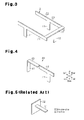
Fig. 3 is a schematic perspective view illustrating another example of an antenna; -
Fig. 4 is a schematic perspective view illustrating a further example of an antenna; and -
Fig. 5 is a schematic perspective view illustrating a conventional plate-like antenna that is cantilevered. - One embodiment of an antenna device will now be described with reference to
Figs. 1, 2A, and 2B . In the present embodiment, anantenna device 1 is installed in, for example, a vehicle (vehicle door). - Referring to
Fig. 1 , theantenna device 1 includes a substrate 2, which serves as a base plate, and an antenna 3 (antenna element), which is coupled to an upper surface of the substrate 2. The antenna 3 receives a wireless signal transmitted from a vehicle electronic key (not illustrated) and sends the received signal to an electronic circuit (not illustrated) in the substrate 2. - The antenna 3 is formed by punching out a metal piece having a predetermined pattern from a sheet of metal plate and then bending the metal piece. The antenna 3 includes a plurality of (three in the present example)
legs 11 to 13, extending orthogonal to the substrate 2, and a frame-shaped arm portion 20, supported by thelegs 11 to 13. Thearm portion 20 includes a plurality of (four in the present example)arms 21 to 24. Thelegs 11 to 13 and thearms 21 to 24 are plate-like and have a uniform thickness. - The
leg 11 extends in the upward direction from the upper surface of the substrate 2. Theleg 11 has a thickness in a first direction (front-to-rear direction inFig. 1 ) that is parallel to the substrate 2. That is, the thickness-wise direction of theleg 11 is set in the first direction. Theleg 11 has a distal portion on which thearm 21 is arranged. Thearm 21 extends in a second direction (left-to-right direction inFig. 1 ) that is parallel to the substrate 2 and perpendicular to the first direction. Accordingly, thearm 21 is perpendicular to theleg 11. Thearm 21 has a thickness in the first direction. That is, the thickness-wise direction of thearm 21 is set in the first direction. As illustrated inFig. 1 , thearm 21 and theleg 11 include continuous front surfaces and continuous rear surfaces. As illustrated inFig. 2B , theleg 11 and thearm 21 are T-shaped as a whole. - The
arm 21 includes aright end 21a and aleft end 21b as illustrated inFig. 1 . Thearm 22 is arranged on theright end 21a of thearm 21. Thearm 22 extends in the first direction (front-to-rear direction) from theright end 21a of thearm 21. Thearm 22 is continuous with the upper end surface of thearm 21 and extends in the rear direction from theright end 21a of thearm 21. Accordingly, thearm 21 and thearm 22 are perpendicular to each other. Thearm 22 has a thickness in a third direction (vertical direction, or up-to-down direction inFig. 1 ). That is, the thickness-wise direction ofarm 22 is set in the third direction. As illustrated inFig. 2B , thearm 22 and thearm 21 include continuous right end surfaces. As illustrated inFig. 1 , thearm 22 includes afront end 22b, which is continuous with thearm 21, and an oppositerear end 22a. Theleg 12, which extends in the upward direction from the upper surface of the substrate 2, supports thearm 22 between thefront end 22b and therear end 22a. Accordingly, thearm 22 and theleg 12 are perpendicular to each other. Theleg 12 has a thickness in the second direction (left-to-right direction). That is, the thickness-wise direction of theleg 12 is set in the second direction. As illustrated inFig. 2B , theleg 12 includes a left surface that is continuous with a left end surface of thearm 22. As illustrated inFig. 1 , theleg 12 and thearm 22 are T-shaped as a whole. - As illustrated in
Fig. 1 , thearm 23 extends in the second direction (left-to-right direction) from therear end 22a of thearm 22. Thearm 23 is continuous with an upper surface of thearm 22 and extends in the left direction from therear end 22a of thearm 22. Accordingly, thearm 22 and thearm 23 are perpendicular to each other. Thearm 23 has a thickness in the first direction (front-to-rear direction). That is, the thickness-wise direction of thearm 23 is set in the first direction. Thearm 23 includes aright end 23b, which is continuous with thearm 22, and an oppositeleft end 23a. Theleg 13, which extends in the upward direction from the upper surface of the substrate 2, supports thearm 23 between theright end 23b and theleft end 23a. Accordingly, thearm 23 and theleg 13 are perpendicular to each other. Theleg 13 has a thickness in the first direction (front-to-rear direction). That is, the thickness-wise direction of theleg 13 is set in the first direction. As illustrated inFig. 1 , thearm 23 and theleg 13 include continuous front surfaces and continuous rear surfaces. As illustrated inFig. 2B , theleg 13 and thearm 23 are T-shaped as a whole. - As illustrated in
Fig. 1 , thearm 24 extends from theleft end 23a of thearm 23 in the first direction (front-to-rear direction). Thearm 24 is continuous with the upper end surface of thearm 23 and extends in the front direction from theleft end 23a of thearm 23. Accordingly, thearm 24 and thearm 23 are perpendicular to each other. Thearm 24 has a thickness in the third direction (up-to-down direction). That is, the thickness-wise direction of thearm 24 is set in the third direction. Thearm 24 includes arear end 24b, which is continuous with thearm 23, and an oppositefront end 24a. Thefront end 24a of thearm 24 includes an upper surface that is continuous with the upper end surface of theleft end 21b of thearm 21. Thearm 24 and thearm 21 are perpendicular to each other. Thearm 21 and thearm 23 both support thearm 24. As illustrated inFig. 2B , thearm 24 includes a left end surface that is continuous with a left end surface of thearm 21 and a left end surface of thearm 23. - As illustrated in
Figs. 2A and 2B , theleg 11 includes a left end surface separated by distance d1 from the right end surface (inner end surface) of thearm 24. Further, theleg 13 includes a left end surface separated by distance d2 from the right end surface of thearm 24. The distances d1 and d2 are set as coprime values. - The operation of the antenna 3 when vibration occurs in the device on which the antenna 3 is arranged, e.g., the vehicle door (not illustrated) in the present embodiment, will now be described. A case in which the substrate 2 vibrates in the first direction (front-to-rear direction) of
Fig. 1 will now be described. - A vibrational wave generated by the vibration of the substrate 2 is transmitted to the
legs 11 to 13. Under this situation, a plate member having a thickness-wise direction that is the same as the vibrational direction vibrates greatly and easily transmits vibrational waves, whereas a plate member having a thickness-wise direction that differs from the vibrational direction vibrates slightly and subtly transmits vibrational waves. Accordingly, when two plate members having different thickness-wise directions are perpendicular to each other, the transmission of vibrational waves from one plate member to the other plate member is suppressed. Referring toFig. 2A , the thickness-wise direction of theleg 12 is set in the second direction (left-to-right direction) that differs from the vibrational direction of the substrate 2 (here, the first direction). Accordingly, theleg 12 resists the transmission of vibrational waves. Further, referring toFig. 2B , the thickness-wise direction of thearm 22, which is continuous with theleg 12, is set in the third direction (up-to-down direction) that differs from the vibrational direction of the substrate 2. Accordingly, thearm 22 also resists the transmission of vibrational waves. This suppresses resonance of theleg 12 and thearm 22. - Referring to
Fig. 2A , the thickness-wise direction of each of thelegs legs arm 21, which is continuous with theleg 11, and thearm 23, which is continuous with theleg 13, easily transmit vibrational waves. However, thearms arm 22 at the right ends 21a and 23b, and the thickness-wise direction of each of thearms 21 and 23 (first direction) differs from the thickness-wise direction of the arm 22 (third direction). Accordingly, vibrational waves are subtly transmitted from thearms arm 22, and resonance of thearm 22 is suppressed. Further, resonance of thearms legs - The
arms arm 24 at the left ends 21b and 23a. Referring toFigs. 2A and 2B , the left end surface of theleg 11 is separated by distance d1 from the right end surface of thearm 24. The left end surface of theleg 13 is separated by distance d2 from the right end surface of thearm 24. The distances d1 and d2 are set as coprime values. Thus, the wavelength of the vibrational waves transmitted from thearm 21 to thearm 24 differs from the wavelength of the vibrational waves transmitted from thearm 23 to thearm 24. Accordingly, resonance is substantially not generated at thearm 24 where the vibrational waves having different wavelengths are transmitted. This suppresses resonance of thearms legs arms leg 11, which is continuous with thearm 21, and theleg 13, which is continuous with thearm 23. In this manner, resonance of the antenna 3 is suppressed, and the generation of vibrational noise that would be caused by the resonance is suppressed. - A case in which the substrate 2 vibrates in the second direction (left-to-right direction) of
Fig. 1 will now be described. - When the substrate 2 vibrates in the second direction (left-to-right direction), vibrational waves are transmitted to the
legs 11 to 13. Referring toFig. 2A , the thickness-wise direction of each of thelegs legs Fig. 2B , the thickness-wise direction of each of thearms legs arms legs arms legs arms - Referring to
Fig. 2A , the thickness direction of theleg 12 is set in the second direction (left-to-right direction), which is the same as the vibrational direction of the substrate 2 (here, the second direction). Accordingly, theleg 12 easily transmits vibrational waves. However, the thickness-wise direction of thearm 22, which is continuous with theleg 12, is set in the third direction (up-to-down direction) that differs from the vibrational direction of the substrate 2. Accordingly, thearm 22 resists the transmission of vibrational waves. Further, thearm 22 is perpendicular to thearms front end 22b and therear end 22a, and the thickness-wise direction of the arm 22 (third direction) differs from the thickness-wise direction of each of thearms 21 and 23 (first direction). Accordingly, vibrational waves are subtly transmitted from thearm 22 to thearms arms leg 12, which is continuous with thearm 22. - Further, the thickness-wise direction of the
arm 24 is set in the third direction (up-to-down direction) that differs from the vibrational direction of the substrate 2 (here, the second direction). Accordingly, thearm 24 resists transmission of vibrational waves. Thearm 24 is continuous with thearms arm 24. In this manner, resonance of the antenna 3 is suppressed, and the generation of vibrational noise that would be caused by the resonance is suppressed. - A case in which the substrate 2 vibrates in the third direction (up-to-down direction) of
Fig. 1 will now be described. - When the substrate 2 vibrates in the third direction (up-to-down direction), vibrational waves are transmitted to the
legs 11 to 13. Referring toFig. 2A , the thickness-wise direction of each of thelegs legs Fig. 2B , the thickness-wise direction of each of thearms legs arms legs arms legs arms - Referring to
Fig. 2A , the thickness direction of theleg 12 is set in the second direction (left-to-right direction), which differs from the vibrational direction of the substrate 2 (here, the third direction). Accordingly, theleg 12 resists the transmission of vibrational waves. In contrast, the thickness-wise direction of thearm 22, which is continuous with theleg 12, is set in the third direction (up-to-down direction), which is the same as the vibrational direction of the substrate 2. Accordingly, thearm 22 easily transmits vibrational waves. However, thearm 22 is continuous with thearms front end 22b and therear end 22a. This suppresses resonance of thearm 22. - The thickness-wise direction of the
arm 24 is set in the third direction (up-to-down direction), which is the same as the vibrational direction of the substrate 2 (here, the third direction). Accordingly, thearm 24 easily transmits vibrational waves. However, thearm 24 is perpendicular to thearms front end 24a and therear end 24b. The thickness-wise direction of each of thearms arms arm 24, which is continuous with thearms Figs. 2A and 2B , the left end surface of theleg 11 is separated by distance d1 from the right end surface of thearm 24, and the left end surface of theleg 13 is separated by distance d2 from the right end surface of thearm 24. The distances d1 and d2 are set as coprime values. Thus, the wavelength of the vibrational waves transmitted from thearm 21 to thearm 24 differs from the wavelength of the vibrational waves transmitted from thearm 23 to thearm 24. Accordingly, resonance is substantially not generated at thearm 24 where vibrational waves having difference wavelengths are transmitted. In this manner, resonance of the antenna 3 is suppressed, and the generation of vibrational noise that would be caused by the resonance is suppressed. - The present embodiment has the advantages described below.
- (1) The antenna 3 includes the plate-
like legs 11 to 13 and the plate-like arms 21 to 24. The thickness-wise direction of each of thelegs arms Fig. 1 ). The thickness-wise direction of theleg 12 is set in the second direction (left-to-right direction inFig. 1 ) that differs from the first direction. The thickness-wise direction of each of thearms Fig. 1 ) that differs from the first and second directions. The plate-like members easily transmit vibrational waves when vibrated in the same direction as the thickness-wise direction, and resist the transmission of vibrational waves when vibrated in a direction differing from the thickness-wise direction. In the antenna 3, the thickness-wise direction of thelegs leg 12. Accordingly, thelegs leg 12 suppresses the transmission of vibration to thearms 21 to 24. Additionally, the thickness-wise direction of each of thearms arms arms arms arms 21 to 24. In this manner, the antenna 3 includes legs and arms that suppress the transmission of vibrational waves regardless of the vibrational direction of the antenna 3. Thus, the antenna 3 resists resonance regardless of the direction of vibration, and the generation of vibrational noise that would be caused by the resonance of the antenna 3 is suppressed. - (2) The
arms arms - (3) The left end surface of the
leg 11 is separated by distance d1 from the right end surface of thearm 24. Further, the left end surface of theleg 13 is separated by distance d2 from the right end surface of thearm 24. The distance d1 and the distance d2 are set as coprime values. As a result, when vibration of the substrate 2 transmits vibrational waves to thearms arms arm 24, which is supported from two sides by thearms - Thus, resonance is suppressed at the
arm 24, and the generation of vibrational noise caused by the resonance of the antenna 3 is suppressed. - It should be apparent to those skilled in the art that the present invention may be embodied in many other specific forms without departing from the spirit or scope of the invention. Particularly, it should be understood that the present invention may be embodied in the following forms.
- In the above embodiment, the
arm 24 may be omitted. In this case, as illustrated inFig. 3 , thearm portion 20 is C-shaped or U-shaped as viewed from above. Further, although not illustrated in the drawings, in the above embodiment, theleg 12 and thearm 22 may be omitted. That is, thearm portion 20 does not have to be frame-shaped. Further, although not illustrated in the drawings, in the above embodiment, thearm 24 and theleg 11 may be omitted. Alternatively, thearm 24 and theleg 13 may be omitted. Further, in the above embodiment, theleg 11 and thearms leg 13 and thearms arm portion 20 is L-shaped as viewed from above. In other words, the antenna 3 only needs to include two or more legs and two or more arms. Such a structure also obtains advantages (1) and (2). - In the above embodiment, a leg extending in the upward direction from the upper surface of the substrate 2 may support the
arm 24. In this case, thearm portion 20 is supported by four legs. That is, thearm portion 20 only needs to be supported by a plurality of legs having different thickness-wise directions. Such a structure also includes the same advantages as the above embodiment. - In the above embodiment, adjacent ones of the
arms 21 to 24 are perpendicular to each other but do not necessarily have to be perpendicular. For example, as illustrated inFig. 4 , anantenna 40 may include twolegs arms legs leg 41 is set in a first direction (for example, left-to-right direction). The thickness-wise direction of theleg 42 is set in the second direction (for example, front-to-rear direction) that differs from the first direction. Thearm 43 extends in the first direction (left-to-right direction). The thickness-wise direction of thearm 43 is set in the third direction (for example, up-to-down direction) that differs from the first and second directions. Thearm 44 extends in the first direction (left-to-right direction). The thickness-wise direction of thearm 44 is set in the second direction (front-to-rear direction). As illustrated inFig. 4 , thearm 44 has a left end that is continuous with a right end of thearm 43. In such a structure, when vibration is produced in the front-to-rear direction and the up-to-down direction, theleg 41 suppresses the transmission of vibrational waves. Further, when vibration is produced in the left-to-right direction and the up-to-down direction, theleg 42 suppresses the transmission of vibrational waves. When vibration is produced in the front-to-rear direction and the left-to-right direction, thearm 43 suppresses the transmission of vibrational waves. When vibration is produced in the left-to-right direction and the up-to-down direction, thearm 44 suppresses the transmission of vibrational waves. In this manner, theantenna 40 includes legs and arms that suppress the transmission of vibrational waves regardless of the vibrational direction of theantenna 40. Thus, theantenna 40 resists resonance regardless of the direction of vibration. This suppresses the generation of vibrational noise caused by resonance of theantenna 40. - In the above embodiment, the width of the
arms 21 and 23 (i.e., length in the up-to-down direction) may be decreased to increase the distance from the upper surface of the substrate 2 to the lower end surfaces of thearms - In the above embodiment, each of the
legs 11 to 13 and thearms 21 to 24 includes an end surface that is continuous with the end surface of the adjacent member (adjacent arm or leg). However, for example, like thearms Fig. 4 , two adjacent members only need to be continuous with each other, and the end surfaces of two adjacent members do not necessarily have to be continuous. - In the above embodiment, the thickness-wise direction of each of the
legs 11 to 13 and thearms 21 to 24 is set to be orthogonal or parallel to the upper surface of the substrate 2, but may be set in the other direction. That is, thelegs 11 to 13 and thearms 21 to 24 only need to be arranged so that two adjacent members (adjacent arms, or adjacent arm and leg) have different thickness-wise directions. - In the above embodiment, the
legs 11 to 13 and thearms 21 to 24 are plate members having rectangular cross-sections but may be plate-like members having elliptic cross-sections. Even in such a case, each of the legs and arms also has a thickness-wise direction. Thus, the same advantages as the above embodiment are obtained. - In the above embodiment, the
antenna device 1 is arranged in a vehicle door but may be arranged at any location in the vehicle. Further, theantenna device 1 may be arranged in an apparatus other than a vehicle. For example, theantenna devices 1 of the above embodiment and modifications may be used as any antenna device attached to any apparatus that may vibrate, such as a door of a building. - The present examples and embodiments are to be considered as illustrative and not restrictive, and the invention is not to be limited to the details given herein, but may be modified within the scope and equivalence of the appended claims.
- An antenna device (1) includes an antenna (3). The antenna (3) includes a plurality of plate-like legs (11-13), coupled to a base plate (2), and a plurality of plate-like arms (21-23), supported by the legs (11-13). Adjacent ones of the arms are continuous with each other. At least two (11,12; 12,13) of the legs have thicknesses in different thickness-wise directions.
Claims (8)
- An antenna device (1) comprising:an antenna (3; 40) including
a plurality of plate-like legs (11-13; 41-42) coupled to a base plate (2), and
a plurality of plate-like arms (21-23; 21-24; 43-44) supported by the legs (11-13; 41-42), wherein adjacent ones of the arms are continuous with each other,
wherein at least two (11,12; 12,13; 41,42) of the legs have thicknesses in different thickness-wise directions. - The antenna device (1) according to claim 1, wherein at least two (21,22; 22,23; 43,44) of the arms have thicknesses in different thickness-wise directions.
- The antenna device (1) according to claim 1 or 2, wherein the arms includes an arm (22; 43) directly supported by one (12; 41) of the legs, and the thickness-wise direction of the supported arm (22; 43) differs from the thickness-wise direction of the one (12; 41) of the legs that directly supports the arm (22; 43).
- The antenna device (1) according to claim 3, wherein the thickness-wise direction of the supported arm (22; 43) is perpendicular to the thickness-wise direction of the one (12; 41) of the legs that directly supports the arm (22; 43).
- The antenna device (1) according to any one of claims 1 to 4, wherein adjacent ones (21,22; 22,23; 43,44) of the arms have different thickness-wise directions.
- The antenna device (1) according to claim 5, wherein the thickness-wise directions of adjacent ones (21,22; 22,23; 43,44) of the arms are perpendicular to each other.
- The antenna device (1) according to any one of claims 1 to 6, wherein
the legs include a first leg (11) and a second leg (13),
the arms include a first arm (21), which is continuous with the first leg (11), a second arm (23), which is continuous with the second leg (13), and a third arm (24), which is supported from two sides by the first and second arms (21,23), and
a distance (d1) from the third arm (24) to the first leg (11) and a distance (d2) from the third arm (24) to the second leg (13) are set as coprime values. - The antenna device (1) according to any one of claims 1 to 6, wherein
the legs include
a first leg (11; 13) set to have a thickness-wise direction in a first direction that extends parallel to the base plate (2), and
a second leg (12) set to have a thickness-wise direction in a second direction that extends parallel to the base plate (2) and differs from the first direction; and
the arms include
a first arm (21; 23) continuous with the first leg (11; 13) and set to have a thickness-wise direction in the first direction, and
a second arm (22) continuous with the second leg (12) and set to have a thickness-wise direction in a third direction that differs from the first and second directions.
Applications Claiming Priority (1)
| Application Number | Priority Date | Filing Date | Title |
|---|---|---|---|
| JP2012172099A JP5886710B2 (en) | 2012-08-02 | 2012-08-02 | antenna |
Publications (2)
| Publication Number | Publication Date |
|---|---|
| EP2693561A1 true EP2693561A1 (en) | 2014-02-05 |
| EP2693561B1 EP2693561B1 (en) | 2021-02-24 |
Family
ID=48875607
Family Applications (1)
| Application Number | Title | Priority Date | Filing Date |
|---|---|---|---|
| EP13178457.1A Active EP2693561B1 (en) | 2012-08-02 | 2013-07-30 | Antenna device |
Country Status (4)
| Country | Link |
|---|---|
| US (1) | US9293811B2 (en) |
| EP (1) | EP2693561B1 (en) |
| JP (1) | JP5886710B2 (en) |
| CN (1) | CN103579765B (en) |
Families Citing this family (3)
| Publication number | Priority date | Publication date | Assignee | Title |
|---|---|---|---|---|
| USD788078S1 (en) * | 2014-01-22 | 2017-05-30 | Agc Automotive Americas R&D, Inc. | Antenna |
| JP6885733B2 (en) * | 2017-01-19 | 2021-06-16 | 株式会社ザクティ | Drive recorder device |
| US11821572B2 (en) | 2021-03-18 | 2023-11-21 | Raytheon Company | Laterally compliant mounting structure |
Citations (5)
| Publication number | Priority date | Publication date | Assignee | Title |
|---|---|---|---|---|
| JP2002356855A (en) * | 2001-05-30 | 2002-12-13 | Toda Constr Co Ltd | Foundation for temporary objects |
| US20040075611A1 (en) * | 2002-10-22 | 2004-04-22 | Robert Kenoun | Reconfigurable antenna for multiband operation |
| JP2010161725A (en) * | 2009-01-09 | 2010-07-22 | Tokai Rika Co Ltd | Antenna holding structure and antenna apparatus |
| JP2011188365A (en) * | 2010-03-10 | 2011-09-22 | Tokai Rika Co Ltd | Antenna device |
| JP2012029137A (en) | 2010-07-26 | 2012-02-09 | Denso Corp | Antenna device |
Family Cites Families (12)
| Publication number | Priority date | Publication date | Assignee | Title |
|---|---|---|---|---|
| TW320813B (en) * | 1996-04-05 | 1997-11-21 | Omron Tateisi Electronics Co | |
| US6573869B2 (en) * | 2001-03-21 | 2003-06-03 | Amphenol - T&M Antennas | Multiband PIFA antenna for portable devices |
| WO2003085780A1 (en) * | 2002-04-04 | 2003-10-16 | Molex Incorporated | Tri-band antenna |
| US6850200B2 (en) * | 2003-06-13 | 2005-02-01 | Motorola, Inc. | Compact PIFA antenna for automated manufacturing |
| US7050011B2 (en) * | 2003-12-31 | 2006-05-23 | Lear Corporation | Low profile antenna for remote vehicle communication system |
| US7123198B2 (en) * | 2004-06-21 | 2006-10-17 | Motorola, Inc. | Electrically small wideband antenna |
| JP2007158955A (en) * | 2005-12-07 | 2007-06-21 | Alps Electric Co Ltd | On-vehicle antenna system |
| JP4780662B2 (en) * | 2006-06-15 | 2011-09-28 | 株式会社ヨコオ | Planar antenna |
| US7830327B2 (en) * | 2007-05-18 | 2010-11-09 | Powerwave Technologies, Inc. | Low cost antenna design for wireless communications |
| DE102007042901A1 (en) * | 2007-09-08 | 2009-03-12 | Leopold Kostal Gmbh & Co. Kg | Remote control or communication device |
| TWI456833B (en) * | 2010-07-09 | 2014-10-11 | Realtek Semiconductor Corp | Inverted-f antenna and wireless communication apparatus using the same |
| CN102299406B (en) * | 2011-06-16 | 2014-09-24 | 上海安费诺永亿通讯电子有限公司 | Multi-frequency antenna used for mobile terminal |
-
2012
- 2012-08-02 JP JP2012172099A patent/JP5886710B2/en active Active
-
2013
- 2013-07-23 US US13/948,545 patent/US9293811B2/en active Active
- 2013-07-26 CN CN201310320280.XA patent/CN103579765B/en not_active Expired - Fee Related
- 2013-07-30 EP EP13178457.1A patent/EP2693561B1/en active Active
Patent Citations (5)
| Publication number | Priority date | Publication date | Assignee | Title |
|---|---|---|---|---|
| JP2002356855A (en) * | 2001-05-30 | 2002-12-13 | Toda Constr Co Ltd | Foundation for temporary objects |
| US20040075611A1 (en) * | 2002-10-22 | 2004-04-22 | Robert Kenoun | Reconfigurable antenna for multiband operation |
| JP2010161725A (en) * | 2009-01-09 | 2010-07-22 | Tokai Rika Co Ltd | Antenna holding structure and antenna apparatus |
| JP2011188365A (en) * | 2010-03-10 | 2011-09-22 | Tokai Rika Co Ltd | Antenna device |
| JP2012029137A (en) | 2010-07-26 | 2012-02-09 | Denso Corp | Antenna device |
Also Published As
| Publication number | Publication date |
|---|---|
| JP2014033308A (en) | 2014-02-20 |
| US20140035785A1 (en) | 2014-02-06 |
| EP2693561B1 (en) | 2021-02-24 |
| CN103579765A (en) | 2014-02-12 |
| CN103579765B (en) | 2017-08-04 |
| JP5886710B2 (en) | 2016-03-16 |
| US9293811B2 (en) | 2016-03-22 |
Similar Documents
| Publication | Publication Date | Title |
|---|---|---|
| EP2693561B1 (en) | Antenna device | |
| JP2015117742A (en) | Mounting structure for in-vehicle equipment | |
| EP3675609B1 (en) | Electronic control component bracket | |
| US10097056B2 (en) | Vibration motor | |
| JP5706796B2 (en) | Electrodynamic exciter | |
| JP6676500B2 (en) | Dynamic damper and ceiling | |
| KR20220100979A (en) | tactile presenting device | |
| US10617019B2 (en) | Board holding apparatus | |
| JP4857935B2 (en) | Shield structure | |
| CN102437861A (en) | Electronic device and bluetooth component thereof | |
| JP4130837B2 (en) | Stage reaction force processing equipment | |
| JP6448358B2 (en) | Antenna unit | |
| JP6565469B2 (en) | Vibration control device and processing machine | |
| CN203632857U (en) | Electromagnetic driving device | |
| JP2013109141A (en) | Image forming apparatus | |
| CN103686019A (en) | Display device | |
| JP2017131025A (en) | Board, and fixing method for housing apparatus | |
| JP2003168886A (en) | Shielding device | |
| JP6161502B2 (en) | Automotive electronic devices | |
| JP6111023B2 (en) | Electronic component mounting device | |
| JP4161991B2 (en) | Speaker stand | |
| WO2018198520A1 (en) | Case and electronic device | |
| JP7314551B2 (en) | Electronics | |
| US10581174B2 (en) | Wireless communication device and antenna thereof | |
| US20240077590A1 (en) | Lidar and manufacturing method of the same |
Legal Events
| Date | Code | Title | Description |
|---|---|---|---|
| AK | Designated contracting states |
Kind code of ref document: A1 Designated state(s): AL AT BE BG CH CY CZ DE DK EE ES FI FR GB GR HR HU IE IS IT LI LT LU LV MC MK MT NL NO PL PT RO RS SE SI SK SM TR |
|
| AX | Request for extension of the european patent |
Extension state: BA ME |
|
| PUAI | Public reference made under article 153(3) epc to a published international application that has entered the european phase |
Free format text: ORIGINAL CODE: 0009012 |
|
| 17P | Request for examination filed |
Effective date: 20140804 |
|
| RBV | Designated contracting states (corrected) |
Designated state(s): AL AT BE BG CH CY CZ DE DK EE ES FI FR GB GR HR HU IE IS IT LI LT LU LV MC MK MT NL NO PL PT RO RS SE SI SK SM TR |
|
| STAA | Information on the status of an ep patent application or granted ep patent |
Free format text: STATUS: EXAMINATION IS IN PROGRESS |
|
| 17Q | First examination report despatched |
Effective date: 20190218 |
|
| GRAP | Despatch of communication of intention to grant a patent |
Free format text: ORIGINAL CODE: EPIDOSNIGR1 |
|
| STAA | Information on the status of an ep patent application or granted ep patent |
Free format text: STATUS: GRANT OF PATENT IS INTENDED |
|
| INTG | Intention to grant announced |
Effective date: 20201112 |
|
| GRAS | Grant fee paid |
Free format text: ORIGINAL CODE: EPIDOSNIGR3 |
|
| GRAA | (expected) grant |
Free format text: ORIGINAL CODE: 0009210 |
|
| STAA | Information on the status of an ep patent application or granted ep patent |
Free format text: STATUS: THE PATENT HAS BEEN GRANTED |
|
| AK | Designated contracting states |
Kind code of ref document: B1 Designated state(s): AL AT BE BG CH CY CZ DE DK EE ES FI FR GB GR HR HU IE IS IT LI LT LU LV MC MK MT NL NO PL PT RO RS SE SI SK SM TR |
|
| REG | Reference to a national code |
Ref country code: GB Ref legal event code: FG4D |
|
| REG | Reference to a national code |
Ref country code: CH Ref legal event code: EP |
|
| REG | Reference to a national code |
Ref country code: AT Ref legal event code: REF Ref document number: 1365636 Country of ref document: AT Kind code of ref document: T Effective date: 20210315 |
|
| REG | Reference to a national code |
Ref country code: IE Ref legal event code: FG4D |
|
| REG | Reference to a national code |
Ref country code: DE Ref legal event code: R096 Ref document number: 602013075816 Country of ref document: DE |
|
| REG | Reference to a national code |
Ref country code: LT Ref legal event code: MG9D |
|
| REG | Reference to a national code |
Ref country code: NL Ref legal event code: MP Effective date: 20210224 |
|
| PG25 | Lapsed in a contracting state [announced via postgrant information from national office to epo] |
Ref country code: LT Free format text: LAPSE BECAUSE OF FAILURE TO SUBMIT A TRANSLATION OF THE DESCRIPTION OR TO PAY THE FEE WITHIN THE PRESCRIBED TIME-LIMIT Effective date: 20210224 Ref country code: PT Free format text: LAPSE BECAUSE OF FAILURE TO SUBMIT A TRANSLATION OF THE DESCRIPTION OR TO PAY THE FEE WITHIN THE PRESCRIBED TIME-LIMIT Effective date: 20210624 Ref country code: FI Free format text: LAPSE BECAUSE OF FAILURE TO SUBMIT A TRANSLATION OF THE DESCRIPTION OR TO PAY THE FEE WITHIN THE PRESCRIBED TIME-LIMIT Effective date: 20210224 Ref country code: HR Free format text: LAPSE BECAUSE OF FAILURE TO SUBMIT A TRANSLATION OF THE DESCRIPTION OR TO PAY THE FEE WITHIN THE PRESCRIBED TIME-LIMIT Effective date: 20210224 Ref country code: GR Free format text: LAPSE BECAUSE OF FAILURE TO SUBMIT A TRANSLATION OF THE DESCRIPTION OR TO PAY THE FEE WITHIN THE PRESCRIBED TIME-LIMIT Effective date: 20210525 Ref country code: BG Free format text: LAPSE BECAUSE OF FAILURE TO SUBMIT A TRANSLATION OF THE DESCRIPTION OR TO PAY THE FEE WITHIN THE PRESCRIBED TIME-LIMIT Effective date: 20210524 Ref country code: NO Free format text: LAPSE BECAUSE OF FAILURE TO SUBMIT A TRANSLATION OF THE DESCRIPTION OR TO PAY THE FEE WITHIN THE PRESCRIBED TIME-LIMIT Effective date: 20210524 |
|
| REG | Reference to a national code |
Ref country code: AT Ref legal event code: MK05 Ref document number: 1365636 Country of ref document: AT Kind code of ref document: T Effective date: 20210224 |
|
| PG25 | Lapsed in a contracting state [announced via postgrant information from national office to epo] |
Ref country code: SE Free format text: LAPSE BECAUSE OF FAILURE TO SUBMIT A TRANSLATION OF THE DESCRIPTION OR TO PAY THE FEE WITHIN THE PRESCRIBED TIME-LIMIT Effective date: 20210224 Ref country code: RS Free format text: LAPSE BECAUSE OF FAILURE TO SUBMIT A TRANSLATION OF THE DESCRIPTION OR TO PAY THE FEE WITHIN THE PRESCRIBED TIME-LIMIT Effective date: 20210224 Ref country code: LV Free format text: LAPSE BECAUSE OF FAILURE TO SUBMIT A TRANSLATION OF THE DESCRIPTION OR TO PAY THE FEE WITHIN THE PRESCRIBED TIME-LIMIT Effective date: 20210224 Ref country code: PL Free format text: LAPSE BECAUSE OF FAILURE TO SUBMIT A TRANSLATION OF THE DESCRIPTION OR TO PAY THE FEE WITHIN THE PRESCRIBED TIME-LIMIT Effective date: 20210224 Ref country code: NL Free format text: LAPSE BECAUSE OF FAILURE TO SUBMIT A TRANSLATION OF THE DESCRIPTION OR TO PAY THE FEE WITHIN THE PRESCRIBED TIME-LIMIT Effective date: 20210224 |
|
| PG25 | Lapsed in a contracting state [announced via postgrant information from national office to epo] |
Ref country code: IS Free format text: LAPSE BECAUSE OF FAILURE TO SUBMIT A TRANSLATION OF THE DESCRIPTION OR TO PAY THE FEE WITHIN THE PRESCRIBED TIME-LIMIT Effective date: 20210624 |
|
| PG25 | Lapsed in a contracting state [announced via postgrant information from national office to epo] |
Ref country code: AT Free format text: LAPSE BECAUSE OF FAILURE TO SUBMIT A TRANSLATION OF THE DESCRIPTION OR TO PAY THE FEE WITHIN THE PRESCRIBED TIME-LIMIT Effective date: 20210224 Ref country code: SM Free format text: LAPSE BECAUSE OF FAILURE TO SUBMIT A TRANSLATION OF THE DESCRIPTION OR TO PAY THE FEE WITHIN THE PRESCRIBED TIME-LIMIT Effective date: 20210224 Ref country code: EE Free format text: LAPSE BECAUSE OF FAILURE TO SUBMIT A TRANSLATION OF THE DESCRIPTION OR TO PAY THE FEE WITHIN THE PRESCRIBED TIME-LIMIT Effective date: 20210224 Ref country code: CZ Free format text: LAPSE BECAUSE OF FAILURE TO SUBMIT A TRANSLATION OF THE DESCRIPTION OR TO PAY THE FEE WITHIN THE PRESCRIBED TIME-LIMIT Effective date: 20210224 |
|
| REG | Reference to a national code |
Ref country code: DE Ref legal event code: R097 Ref document number: 602013075816 Country of ref document: DE |
|
| PG25 | Lapsed in a contracting state [announced via postgrant information from national office to epo] |
Ref country code: RO Free format text: LAPSE BECAUSE OF FAILURE TO SUBMIT A TRANSLATION OF THE DESCRIPTION OR TO PAY THE FEE WITHIN THE PRESCRIBED TIME-LIMIT Effective date: 20210224 Ref country code: DK Free format text: LAPSE BECAUSE OF FAILURE TO SUBMIT A TRANSLATION OF THE DESCRIPTION OR TO PAY THE FEE WITHIN THE PRESCRIBED TIME-LIMIT Effective date: 20210224 Ref country code: ES Free format text: LAPSE BECAUSE OF FAILURE TO SUBMIT A TRANSLATION OF THE DESCRIPTION OR TO PAY THE FEE WITHIN THE PRESCRIBED TIME-LIMIT Effective date: 20210224 Ref country code: SK Free format text: LAPSE BECAUSE OF FAILURE TO SUBMIT A TRANSLATION OF THE DESCRIPTION OR TO PAY THE FEE WITHIN THE PRESCRIBED TIME-LIMIT Effective date: 20210224 |
|
| PLBE | No opposition filed within time limit |
Free format text: ORIGINAL CODE: 0009261 |
|
| STAA | Information on the status of an ep patent application or granted ep patent |
Free format text: STATUS: NO OPPOSITION FILED WITHIN TIME LIMIT |
|
| PG25 | Lapsed in a contracting state [announced via postgrant information from national office to epo] |
Ref country code: AL Free format text: LAPSE BECAUSE OF FAILURE TO SUBMIT A TRANSLATION OF THE DESCRIPTION OR TO PAY THE FEE WITHIN THE PRESCRIBED TIME-LIMIT Effective date: 20210224 |
|
| 26N | No opposition filed |
Effective date: 20211125 |
|
| PG25 | Lapsed in a contracting state [announced via postgrant information from national office to epo] |
Ref country code: SI Free format text: LAPSE BECAUSE OF FAILURE TO SUBMIT A TRANSLATION OF THE DESCRIPTION OR TO PAY THE FEE WITHIN THE PRESCRIBED TIME-LIMIT Effective date: 20210224 |
|
| REG | Reference to a national code |
Ref country code: CH Ref legal event code: PL |
|
| GBPC | Gb: european patent ceased through non-payment of renewal fee |
Effective date: 20210730 |
|
| PG25 | Lapsed in a contracting state [announced via postgrant information from national office to epo] |
Ref country code: MC Free format text: LAPSE BECAUSE OF FAILURE TO SUBMIT A TRANSLATION OF THE DESCRIPTION OR TO PAY THE FEE WITHIN THE PRESCRIBED TIME-LIMIT Effective date: 20210224 |
|
| REG | Reference to a national code |
Ref country code: BE Ref legal event code: MM Effective date: 20210731 |
|
| PG25 | Lapsed in a contracting state [announced via postgrant information from national office to epo] |
Ref country code: LI Free format text: LAPSE BECAUSE OF NON-PAYMENT OF DUE FEES Effective date: 20210731 Ref country code: IT Free format text: LAPSE BECAUSE OF FAILURE TO SUBMIT A TRANSLATION OF THE DESCRIPTION OR TO PAY THE FEE WITHIN THE PRESCRIBED TIME-LIMIT Effective date: 20210224 Ref country code: GB Free format text: LAPSE BECAUSE OF NON-PAYMENT OF DUE FEES Effective date: 20210730 Ref country code: CH Free format text: LAPSE BECAUSE OF NON-PAYMENT OF DUE FEES Effective date: 20210731 |
|
| REG | Reference to a national code |
Ref country code: DE Ref legal event code: R084 Ref document number: 602013075816 Country of ref document: DE |
|
| PG25 | Lapsed in a contracting state [announced via postgrant information from national office to epo] |
Ref country code: IS Free format text: LAPSE BECAUSE OF FAILURE TO SUBMIT A TRANSLATION OF THE DESCRIPTION OR TO PAY THE FEE WITHIN THE PRESCRIBED TIME-LIMIT Effective date: 20210624 Ref country code: LU Free format text: LAPSE BECAUSE OF NON-PAYMENT OF DUE FEES Effective date: 20210730 Ref country code: FR Free format text: LAPSE BECAUSE OF NON-PAYMENT OF DUE FEES Effective date: 20210731 |
|
| PG25 | Lapsed in a contracting state [announced via postgrant information from national office to epo] |
Ref country code: IE Free format text: LAPSE BECAUSE OF NON-PAYMENT OF DUE FEES Effective date: 20210730 Ref country code: BE Free format text: LAPSE BECAUSE OF NON-PAYMENT OF DUE FEES Effective date: 20210731 |
|
| PG25 | Lapsed in a contracting state [announced via postgrant information from national office to epo] |
Ref country code: HU Free format text: LAPSE BECAUSE OF FAILURE TO SUBMIT A TRANSLATION OF THE DESCRIPTION OR TO PAY THE FEE WITHIN THE PRESCRIBED TIME-LIMIT; INVALID AB INITIO Effective date: 20130730 |
|
| PG25 | Lapsed in a contracting state [announced via postgrant information from national office to epo] |
Ref country code: CY Free format text: LAPSE BECAUSE OF FAILURE TO SUBMIT A TRANSLATION OF THE DESCRIPTION OR TO PAY THE FEE WITHIN THE PRESCRIBED TIME-LIMIT Effective date: 20210224 |
|
| PG25 | Lapsed in a contracting state [announced via postgrant information from national office to epo] |
Ref country code: MK Free format text: LAPSE BECAUSE OF FAILURE TO SUBMIT A TRANSLATION OF THE DESCRIPTION OR TO PAY THE FEE WITHIN THE PRESCRIBED TIME-LIMIT Effective date: 20210224 |
|
| PG25 | Lapsed in a contracting state [announced via postgrant information from national office to epo] |
Ref country code: MT Free format text: LAPSE BECAUSE OF FAILURE TO SUBMIT A TRANSLATION OF THE DESCRIPTION OR TO PAY THE FEE WITHIN THE PRESCRIBED TIME-LIMIT Effective date: 20210224 |
|
| PGFP | Annual fee paid to national office [announced via postgrant information from national office to epo] |
Ref country code: DE Payment date: 20250604 Year of fee payment: 13 |
|
| PG25 | Lapsed in a contracting state [announced via postgrant information from national office to epo] |
Ref country code: TR Free format text: LAPSE BECAUSE OF FAILURE TO SUBMIT A TRANSLATION OF THE DESCRIPTION OR TO PAY THE FEE WITHIN THE PRESCRIBED TIME-LIMIT Effective date: 20210224 |