EP2693531A2 - Connection structure for a secondary battery and battery pack comprising same - Google Patents
Connection structure for a secondary battery and battery pack comprising same Download PDFInfo
- Publication number
- EP2693531A2 EP2693531A2 EP12797404.6A EP12797404A EP2693531A2 EP 2693531 A2 EP2693531 A2 EP 2693531A2 EP 12797404 A EP12797404 A EP 12797404A EP 2693531 A2 EP2693531 A2 EP 2693531A2
- Authority
- EP
- European Patent Office
- Prior art keywords
- unit
- circuit
- secondary battery
- connecting structure
- battery according
- Prior art date
- Legal status (The legal status is an assumption and is not a legal conclusion. Google has not performed a legal analysis and makes no representation as to the accuracy of the status listed.)
- Granted
Links
Images


Classifications
-
- H—ELECTRICITY
- H01—ELECTRIC ELEMENTS
- H01M—PROCESSES OR MEANS, e.g. BATTERIES, FOR THE DIRECT CONVERSION OF CHEMICAL ENERGY INTO ELECTRICAL ENERGY
- H01M10/00—Secondary cells; Manufacture thereof
- H01M10/42—Methods or arrangements for servicing or maintenance of secondary cells or secondary half-cells
- H01M10/425—Structural combination with electronic components, e.g. electronic circuits integrated to the outside of the casing
-
- H—ELECTRICITY
- H01—ELECTRIC ELEMENTS
- H01M—PROCESSES OR MEANS, e.g. BATTERIES, FOR THE DIRECT CONVERSION OF CHEMICAL ENERGY INTO ELECTRICAL ENERGY
- H01M50/00—Constructional details or processes of manufacture of the non-active parts of electrochemical cells other than fuel cells, e.g. hybrid cells
- H01M50/50—Current conducting connections for cells or batteries
- H01M50/531—Electrode connections inside a battery casing
-
- H—ELECTRICITY
- H01—ELECTRIC ELEMENTS
- H01M—PROCESSES OR MEANS, e.g. BATTERIES, FOR THE DIRECT CONVERSION OF CHEMICAL ENERGY INTO ELECTRICAL ENERGY
- H01M10/00—Secondary cells; Manufacture thereof
- H01M10/02—Details
-
- H—ELECTRICITY
- H01—ELECTRIC ELEMENTS
- H01M—PROCESSES OR MEANS, e.g. BATTERIES, FOR THE DIRECT CONVERSION OF CHEMICAL ENERGY INTO ELECTRICAL ENERGY
- H01M50/00—Constructional details or processes of manufacture of the non-active parts of electrochemical cells other than fuel cells, e.g. hybrid cells
- H01M50/20—Mountings; Secondary casings or frames; Racks, modules or packs; Suspension devices; Shock absorbers; Transport or carrying devices; Holders
- H01M50/204—Racks, modules or packs for multiple batteries or multiple cells
- H01M50/207—Racks, modules or packs for multiple batteries or multiple cells characterised by their shape
- H01M50/213—Racks, modules or packs for multiple batteries or multiple cells characterised by their shape adapted for cells having curved cross-section, e.g. round or elliptic
-
- H—ELECTRICITY
- H01—ELECTRIC ELEMENTS
- H01M—PROCESSES OR MEANS, e.g. BATTERIES, FOR THE DIRECT CONVERSION OF CHEMICAL ENERGY INTO ELECTRICAL ENERGY
- H01M50/00—Constructional details or processes of manufacture of the non-active parts of electrochemical cells other than fuel cells, e.g. hybrid cells
- H01M50/50—Current conducting connections for cells or batteries
- H01M50/502—Interconnectors for connecting terminals of adjacent batteries; Interconnectors for connecting cells outside a battery casing
- H01M50/503—Interconnectors for connecting terminals of adjacent batteries; Interconnectors for connecting cells outside a battery casing characterised by the shape of the interconnectors
-
- H—ELECTRICITY
- H01—ELECTRIC ELEMENTS
- H01M—PROCESSES OR MEANS, e.g. BATTERIES, FOR THE DIRECT CONVERSION OF CHEMICAL ENERGY INTO ELECTRICAL ENERGY
- H01M50/00—Constructional details or processes of manufacture of the non-active parts of electrochemical cells other than fuel cells, e.g. hybrid cells
- H01M50/50—Current conducting connections for cells or batteries
- H01M50/502—Interconnectors for connecting terminals of adjacent batteries; Interconnectors for connecting cells outside a battery casing
- H01M50/514—Methods for interconnecting adjacent batteries or cells
- H01M50/517—Methods for interconnecting adjacent batteries or cells by fixing means, e.g. screws, rivets or bolts
-
- H—ELECTRICITY
- H01—ELECTRIC ELEMENTS
- H01M—PROCESSES OR MEANS, e.g. BATTERIES, FOR THE DIRECT CONVERSION OF CHEMICAL ENERGY INTO ELECTRICAL ENERGY
- H01M50/00—Constructional details or processes of manufacture of the non-active parts of electrochemical cells other than fuel cells, e.g. hybrid cells
- H01M50/50—Current conducting connections for cells or batteries
- H01M50/502—Interconnectors for connecting terminals of adjacent batteries; Interconnectors for connecting cells outside a battery casing
- H01M50/519—Interconnectors for connecting terminals of adjacent batteries; Interconnectors for connecting cells outside a battery casing comprising printed circuit boards [PCB]
-
- H—ELECTRICITY
- H01—ELECTRIC ELEMENTS
- H01M—PROCESSES OR MEANS, e.g. BATTERIES, FOR THE DIRECT CONVERSION OF CHEMICAL ENERGY INTO ELECTRICAL ENERGY
- H01M50/00—Constructional details or processes of manufacture of the non-active parts of electrochemical cells other than fuel cells, e.g. hybrid cells
- H01M50/50—Current conducting connections for cells or batteries
- H01M50/502—Interconnectors for connecting terminals of adjacent batteries; Interconnectors for connecting cells outside a battery casing
- H01M50/521—Interconnectors for connecting terminals of adjacent batteries; Interconnectors for connecting cells outside a battery casing characterised by the material
- H01M50/522—Inorganic material
-
- H—ELECTRICITY
- H01—ELECTRIC ELEMENTS
- H01M—PROCESSES OR MEANS, e.g. BATTERIES, FOR THE DIRECT CONVERSION OF CHEMICAL ENERGY INTO ELECTRICAL ENERGY
- H01M50/00—Constructional details or processes of manufacture of the non-active parts of electrochemical cells other than fuel cells, e.g. hybrid cells
- H01M50/50—Current conducting connections for cells or batteries
- H01M50/528—Fixed electrical connections, i.e. not intended for disconnection
-
- H—ELECTRICITY
- H01—ELECTRIC ELEMENTS
- H01M—PROCESSES OR MEANS, e.g. BATTERIES, FOR THE DIRECT CONVERSION OF CHEMICAL ENERGY INTO ELECTRICAL ENERGY
- H01M50/00—Constructional details or processes of manufacture of the non-active parts of electrochemical cells other than fuel cells, e.g. hybrid cells
- H01M50/50—Current conducting connections for cells or batteries
- H01M50/572—Means for preventing undesired use or discharge
- H01M50/574—Devices or arrangements for the interruption of current
-
- H—ELECTRICITY
- H01—ELECTRIC ELEMENTS
- H01R—ELECTRICALLY-CONDUCTIVE CONNECTIONS; STRUCTURAL ASSOCIATIONS OF A PLURALITY OF MUTUALLY-INSULATED ELECTRICAL CONNECTING ELEMENTS; COUPLING DEVICES; CURRENT COLLECTORS
- H01R11/00—Individual connecting elements providing two or more spaced connecting locations for conductive members which are, or may be, thereby interconnected, e.g. end pieces for wires or cables supported by the wire or cable and having means for facilitating electrical connection to some other wire, terminal, or conductive member, blocks of binding posts
- H01R11/11—End pieces or tapping pieces for wires, supported by the wire and for facilitating electrical connection to some other wire, terminal or conductive member
- H01R11/28—End pieces consisting of a ferrule or sleeve
- H01R11/281—End pieces consisting of a ferrule or sleeve for connections to batteries
- H01R11/288—Interconnections between batteries
-
- H—ELECTRICITY
- H01—ELECTRIC ELEMENTS
- H01M—PROCESSES OR MEANS, e.g. BATTERIES, FOR THE DIRECT CONVERSION OF CHEMICAL ENERGY INTO ELECTRICAL ENERGY
- H01M50/00—Constructional details or processes of manufacture of the non-active parts of electrochemical cells other than fuel cells, e.g. hybrid cells
- H01M50/50—Current conducting connections for cells or batteries
- H01M50/543—Terminals
- H01M50/547—Terminals characterised by the disposition of the terminals on the cells
- H01M50/548—Terminals characterised by the disposition of the terminals on the cells on opposite sides of the cell
-
- H—ELECTRICITY
- H01—ELECTRIC ELEMENTS
- H01M—PROCESSES OR MEANS, e.g. BATTERIES, FOR THE DIRECT CONVERSION OF CHEMICAL ENERGY INTO ELECTRICAL ENERGY
- H01M6/00—Primary cells; Manufacture thereof
- H01M6/42—Grouping of primary cells into batteries
- H01M6/44—Grouping of primary cells into batteries of tubular or cup-shaped cells
-
- Y—GENERAL TAGGING OF NEW TECHNOLOGICAL DEVELOPMENTS; GENERAL TAGGING OF CROSS-SECTIONAL TECHNOLOGIES SPANNING OVER SEVERAL SECTIONS OF THE IPC; TECHNICAL SUBJECTS COVERED BY FORMER USPC CROSS-REFERENCE ART COLLECTIONS [XRACs] AND DIGESTS
- Y02—TECHNOLOGIES OR APPLICATIONS FOR MITIGATION OR ADAPTATION AGAINST CLIMATE CHANGE
- Y02E—REDUCTION OF GREENHOUSE GAS [GHG] EMISSIONS, RELATED TO ENERGY GENERATION, TRANSMISSION OR DISTRIBUTION
- Y02E60/00—Enabling technologies; Technologies with a potential or indirect contribution to GHG emissions mitigation
- Y02E60/10—Energy storage using batteries
Definitions
- the present disclosure relates to a connecting structure for a secondary battery, and more particularly, to a connecting structure for a secondary battery, which connects the secondary battery to a protection circuit module, and a secondary battery pack including the same.
- lithium (ion/polymer) secondary batteries with high energy density, high operation voltage and excellent preservation and life characteristics are widely used as energy sources of various electronic products as well as various mobile devices.
- Such secondary batteries may be used as a single battery cell or a battery pack where a plurality of unit cells are electrically connected to each other, depending on the kind of external device used.
- a small-sized device such as a cellular phone may operate for a predetermined time with the power and capacity of a single battery cell, but middle-sized or large-sized devices such as notebooks, portable DVD, electric vehicles and hybrid vehicles demand the use of a battery pack in order to ensure large power and capacity.
- Such a battery pack generally has a 'soft pack' structure, which is prepared by connecting a protection circuit or the like to a 'core pack' having a plurality of unit cells connected in series or in parallel, packed in a hard case.
- a 'soft pack' structure which is prepared by connecting a protection circuit or the like to a 'core pack' having a plurality of unit cells connected in series or in parallel, packed in a hard case.
- unit cells are stacked so that wide surfaces face each other, and then electrode terminals of the unit cells are connected to each other by using a connection member such as a bus bar. Therefore, in case of preparing a cubic battery pack with a hexahedral structure, the rectangular or pouch-type batteries are advantageous as the unit cells.
- a cylindrical battery generally has a higher electric capacity in comparison to a rectangular or pouch-type, a cylindrical battery may not easily stack due to its appearance.
- the battery pack has a linear or plate shape as a whole, the cylindrical battery may have a more structural advantage than the rectangular or pouch-type battery.
- a battery pack is configured with a core pack, in which a plurality of cylindrical batteries is connected in series or in parallel.
- a core pack generally uses a 2P (parallel) - 3S (series) linear structure, a 2P-3S plate structure, a 2P-4S linear structure, a 2P-4S plate structure or the like.
- a parallel-type connection structure is configured by arranging two or more cylindrical batteries to be adjacent to each other in a lateral direction with the electrodes being arranged in the same direction, and then welding the cylindrical batteries by using a connection member.
- This parallel-type cylindrical battery is also called a 'bank'.
- a series-type connection structure is configured by arranging two or more cylindrical batteries in a long length so that electrode terminals with opposite polarities are successively located or by arranging two or more batteries to be adjacent to each other in their lateral direction in a state where electrode terminals are oriented toward opposite directions, and then welding the cylindrical batteries by using a connection member.
- a connection member for electrical connection of such cylindrical batteries a thin metal plate such as a nickel plate is generally used.
- a PCM Protection Circuit Module
- Fig. 1 is a perspective view schematically showing a conventional battery pack.
- Fig. 1 shows a coupling relation between a core pack and a protection circuit module in an exploded view, in which a pack case is not depicted.
- Fig. 1 three electrode pairs of unit cells 11 connected to each other in parallel are connected in series by means of metal plates 20 to form a core pack 10.
- the metal plates 20 connected to the unit cells 11 of the core pack 10 are electrically connected to a protection circuit module 30 by means of soldering or welding.
- the soldering or welding process for the core pack 10 and the protection circuit module 30 has the following problems.
- the welding or soldering process requires the skilled techniques and know-how of workers, and parameters for determining the intensity of welding should be continuously maintained, resulting in complicated and expensive production processes and serving as a factor that deteriorates the production efficiency.
- a short circuit may occur at the connection portion due to vibrations of the battery pack or an external impact, and an electric or thermal damage may be applied to the interface with the metal plate 20, which may become factors that threat the safety of the battery and increase the inferiority of products.
- the sequence of operation should be strictly obeyed during the soldering or welding process for the core pack 10 and the protection circuit module 30. If not, a great voltage is abruptly applied from the core pack 10 to the protection circuit module 30, which may damage the internal circuit of the protection circuit module 30 and cause malfunction. In particular, when there is a defect with a part of the unit cells or the protection circuit module 30 during the production process or in use, there is a disadvantage in that all components of the battery pack must be discarded.
- the present disclosure is designed to solve the problems of the prior art, and therefore it is an object of the present disclosure to provide a connecting structure for a secondary battery, which may allow electric connection using a physical connection method, which allows selective connection and separation, while excluding a soldering or welding process demanding a complicated work procedure, when connecting a core pack and a protection circuit module of a battery pack, and a battery pack including the same.
- a connecting structure for a secondary battery for electrically connecting a core pack in which two or more unit cells are electrically connected and a protection circuit module made of the unit cells of the core pack and a PCB substrate
- the connecting structure including: a metal plate having an electrode connecting unit connected to an electrode of each unit cell of the core pack and a circuit connecting unit connected to the protection circuit module; and a circuit terminal unit electrically connected to the circuit connecting unit by being located in a connection hole formed in the PCB substrate of the protection circuit module so that the upper and lower portions of the PCB substrate communicate with each other, wherein the circuit connecting unit is electrically connected to the circuit terminal unit by means of a physical connection method which allows selective connection and separation.
- the circuit terminal unit is surface-mounted to the upper portion of the connection hole of the PCB substrate and is electrically connected to the protection circuit module.
- the circuit terminal unit has an insert groove into which the circuit connecting unit passing through the connection hole of the PCB substrate is inserted.
- the circuit connecting unit has a plate shape
- the circuit terminal unit further includes an elastic surface surface-contacting with the circuit connecting unit in the insert groove to fix the circuit connecting unit.
- the circuit connecting unit has a plate shape and further has coupling grooves formed at both edges thereof in the width direction.
- the circuit terminal unit further includes an elastic piece inserted into the coupling groove of the circuit connecting unit in the insert groove to fix the circuit connecting unit.
- the circuit terminal unit is inserted into and coupled in the connection hole of the PCB substrate and is electrically connected to the protection circuit module.
- the circuit terminal unit has a cylindrical shape and has a hooking protrusion formed on the outer circumference thereof to pass through the connection hole of the PCB substrate and be coupled to the lower portion of the PCB substrate.
- the circuit connecting unit is fit into the circuit terminal unit.
- the circuit connecting unit has an upper portion bent perpendicularly and has a coupling unit formed at the upper surface thereof so that the circuit terminal unit is coupled thereto by fitting.
- the circuit terminal unit has a cylindrical shape and has a thread formed on the outer circumference thereof with a bolt shape.
- the circuit terminal unit is coupled to the circuit connecting unit located in the connection hole at the lower portion of the PCB substrate by bolt coupling.
- the circuit connecting unit has an upper portion bent perpendicularly and further includes a screw coupling unit formed at the upper surface thereof so that the circuit terminal unit is coupled thereto by bolt coupling.
- the metal plate is made of nickel.
- the unit cell is a cylindrical battery.
- a battery pack including the connecting structure for a secondary battery according to the present disclosure.
- a core pack and a protection circuit module may be electrically connected by using a physical connection method which allows selective connection and separation, while excluding a soldering or welding process demanding a complicated work procedure.
- a physical connection method which allows selective connection and separation, while excluding a soldering or welding process demanding a complicated work procedure.
- the core pack and the protection circuit module may be easily connected and separated, components of the battery pack may be partially reused, exchanged and repaired, which reduces the maintenance cost of the battery pack.
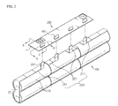
- Fig. 2 is a partially-exploded perspective view schematically showing a battery pack according to a first embodiment of the present disclosure
- Fig. 3 is a cross-sectional view showing an example of a connecting structure for a secondary battery according to the first embodiment of the present disclosure, taken along the line A-A' of Fig. 2
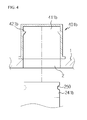
- Fig. 4 is a cross-sectional view showing another example of the connecting structure for a secondary battery according to the first embodiment of the present disclosure, taken along the line B-B' of Fig. 2 .
- a battery pack according to the first embodiment of the present disclosure includes a core pack 100 where six unit cells 110 are arranged in a 2P (parallel) - 3S (series) manner, and a soft pack where a protection circuit module 300 made of a PCB substrate 1 is electrically connected by means of four metal plates 201. Meanwhile, though not shown in Fig. 2 , the soft pack may be sealed in a pack case.
- the core pack 100 may form a single bank by electrically connecting a pair of unit cells 110 in parallel, and three banks may be connected in series.
- each unit cell 110 may be a cylindrical or rectangular battery, but the cylindrical battery is preferred.
- Fig. 2 depicts that the unit cells 110 of the core pack 100 are arranged in a 2P-3S manner, the present disclosure is not limited thereto and various structures such as 1P-2S, 1P-3S, 2P-2S, 2P-4S or the like may be applied, as obvious to those skilled in the art.
- the metal plate 201 is used for electrically connecting each unit cell 110 of the core pack 100 to the protection circuit module 300 and includes an electrode connecting unit 231 connected to an electrode of each unit cell 110 and a circuit connecting unit 241 connected to the protection circuit module 300.
- the metal plate 201 is prepared to have an integrated thin plate structure by using pure nickel, nickel-plated steel sheet (Ni-top) or nickel alloys (Ni-plated copper) and is classified into a metal plate 211 for both terminal potentials which measures maximum and minimum voltages of the core pack 100 and a metal plate 221 for bank potentials which measures voltages among banks.
- the metal plate 201 namely the metal plate 211 for both terminal potentials and the metal plate 221 for bank potentials, is formed to connect to the corresponding unit cell 110, but the present disclosure is not limited to the shape of the metal plate 201.
- the PCM (Protection Circuit Module) 300 is made of the PCB substrate 1 and serve as a BMU (Battery Management Unit) for protecting a battery against dangers such as heating and explosion caused by overcharge or overdischarge of the unit cells 110 or other external physical impacts.
- BMU Battery Management Unit
- connection hole 2 is formed in the PCB substrate 1 of the protection circuit module 300 so that the upper and lower portions of the PCB substrate 1 communicate with each other, and the connecting structure of the present disclosure includes a circuit terminal unit 401 located in the connection hole 2 to be electrically connected to the circuit connecting unit 241 of the metal plate 201.
- the connecting structure for a secondary battery is configured to include circuit connecting units 241a, 241b of the metal plate 201, and circuit terminal units 401a, 401b located at the PCB substrate 1 of the protection circuit module 300, and this structure gives electric connection by a physical connection method which allows selection connection or separation of the circuit connecting units 241a, 241b and the circuit terminal units 401a, 401b.
- the circuit connecting units 241a, 241b has a plate shape and pass through the connection hole 2 of the PCB substrate 1 and are inserted into the circuit terminal units 401a, 401b to electrically connect the core pack 100 and the protection circuit module 300.
- the circuit terminal units 401a, 401b are surface-mounted to the upper portion of the connection hole 2 of the PCB substrate 1 by means of soldering or welding and electrically connected to the protection circuit module 300. At the portion where the circuit terminal units 401a, 401b are surface-mounted, a circuit pattern (not shown) for electrically connecting the protection circuit module 300 is formed on the PCB substrate 1.
- the circuit connecting unit 241a and the circuit terminal unit 401a may be configured.
- the circuit connecting unit 241a has a plate shape, and the circuit terminal unit 401a has an insert groove 411 a into which the plate-shaped circuit connecting unit 241 a is inserted.
- An elastic surface 421a surface-contacting with the circuit connecting unit 241a to fix the circuit connecting unit 241a is provided in the insert groove 411a of the circuit terminal unit 401a.
- the circuit connecting unit 241a is tightly adhered by an elastic force applied by the elastic surface 421a and fixed to the inside of the circuit terminal unit 401a.
- a separate means for selectively releasing the elastic force of the elastic surface 421a may be provided at the circuit terminal unit 401a in order to cut the connection of the circuit connecting unit 241a.
- the circuit connecting unit 241b and the circuit terminal unit 401b may be configured.
- the circuit connecting unit 241b further has coupling grooves 250 formed at both edges in the width direction, and the circuit terminal unit 401b includes an elastic piece 421b inserted into the coupling groove 250 of the circuit connecting unit 241b in the insert groove 411b to fix the circuit connecting unit 241b.
- the circuit connecting unit 241b is fixed at the inside of the circuit terminal unit 401b as the elastic piece 421b is inserted into the coupling groove 250.
- the circuit terminal unit 401b may further include a means for selectively releasing the coupling of the elastic piece 421b in order to cut the connection of the circuit connecting unit 241b.
- Fig. 5 is a partially-exploded perspective view schematically showing a battery pack according to a second embodiment of the present disclosure
- Figs. 6 and 7 are cross-sectional views showing examples of a connecting structure for a secondary battery according to the second embodiment of the present disclosure, taken along the line A-A' of Fig. 5
- Figs. 8 and 9 are cross-sectional views showing other examples of the connecting structure for a secondary battery according to the second embodiment of the present disclosure, taken along the line A-A' of Fig. 5 .
- the battery pack according to the second embodiment of the present disclosure is substantially identical to that of the first embodiment, except for the connecting structure for a secondary battery.
- the second embodiment has differences in the configuration of a metal plate 202 and a circuit terminal unit 402 located at the PCB substrate 1 of the protection circuit module 300. Therefore, the identical components except for the connecting structure for a secondary battery will not be described in detail here.
- the metal plate 202 is used for electrically connecting each unit cell 100 of the core pack 100 to the protection circuit module 300 and includes an electrode connecting unit 232 connected to an electrode of each unit cell 110 and a circuit connecting unit 242 connected to the protection circuit module 300.
- the metal plate 202 is classified into a metal plate 212 for both terminal potentials which measures maximum and minimum voltages of the core pack 100 and a metal plate 222 for bank potentials which measures voltages among banks, similar to the first embodiment.
- the metal plate 202 namely the metal plate 212 for both terminal potentials and the metal plate 222 for bank potentials, is formed to connect to the corresponding unit cell 110, but the present disclosure is not limited to the shape of the metal plate 202.
- connection hole 2 is formed in the PCB substrate 1 of the protection circuit module 300 so that the upper and lower portions of the PCB substrate 1 communicate with each other, and the connecting structure of the present disclosure includes a circuit terminal unit 402 located in the connection hole 2 to be electrically connected to the circuit connecting unit 242 of the metal plate 202.
- the connecting structure for a secondary battery is configured to include a coupling unit 262a or a screw coupling unit 262b provided at the circuit connecting unit 242 of the metal plate 202, and circuit terminal units 402a, 402b located at the PCB substrate 1 of the protection circuit module 300, and this structure gives electric connection by a physical connection method which allows selection connection or separation of the coupling unit 262a or the screw coupling unit 262b of the circuit connecting unit 242 and the circuit terminal units 402a, 402b.
- the circuit terminal units 402a, 402b are inserted into and coupled in the connection hole 2 of the PCB substrate 1 and electrically connected to the protection circuit module 300. At the portion where the circuit terminal units 402a, 402b are coupled, a circuit pattern (not shown) for electrically connecting the protection circuit module 300 is formed on the PCB substrate 1.
- the circuit connecting unit 242 has a plate shape and has an upper portion bent perpendicularly, and a coupling unit 262a or a screw coupling unit 262b is formed at the bent upper surface.
- the coupling unit 262a or the screw coupling unit 262b electrically connects the core pack 100 and the protection circuit module 300, coupled to the circuit terminal units 402a, 402b.
- the coupling unit 262a of the circuit connecting unit 242 and the circuit terminal unit 402a may be configured.
- the circuit terminal unit 402a has a cylindrical shape, and a hooking protrusion 442a is formed on the outer circumference 432a thereof.
- the circuit terminal unit 402a is inserted into and coupled in the connection hole 2 of the PCB substrate 1 by means of the hooking protrusion 442a and electrically connected to the protection circuit module 300.
- the circuit connecting unit 242 includes a cylindrical coupling unit 262a coupled to the PCB substrate 1 and fit into the circuit terminal unit 402a protruding below the PCB substrate 1, and the coupling unit 262a is formed by bending an upper portion of the circuit connecting unit 242 perpendicular and being united to the bent upper surface by means of welding or compression.
- the circuit terminal unit 402a is, as shown in Fig. 7 , inserted into and coupled in the connection hole 2 of the PCB substrate 1, and its cylindrical portion where the hooking protrusion 442a is located protrudes below the PCB substrate 1.
- the coupling unit 262a of the circuit connecting unit 242 is coupled to the protruding portion by fitting and is fixed to the circuit terminal unit 402a. At this time, at the inside of the coupling unit 262a of the circuit connecting unit 242, a groove may be formed so that the hooking protrusion 442a may be fit thereto.
- the screw coupling unit 262b of the circuit connecting unit 242 and the circuit terminal unit 402b may be configured.
- the circuit terminal unit 402b has a cylindrical shape and a thread 452b is formed on the outer circumference thereof with a bolt shape.
- the circuit connecting unit 242 has a screw coupling unit 262b having a thread 272b formed therein to correspond to the thread 452b of the circuit terminal unit 402b so as to be coupled to the circuit terminal unit 402b by bolt coupling, and the screw coupling unit 262b is formed by bending an upper portion of the circuit connecting unit 242 perpendicularly and being united to the bent upper surface by welding or compression.
- the screw coupling unit 262b of the circuit connecting unit 242 is, as shown in Fig. 9 , located at the lower portion of the connection hole 2 of the PCB substrate 1, and the circuit terminal unit 402b passes through the connection hole 2 of the PCB substrate 1 and is bolt-coupled to the screw coupling unit 262b so as to fix the screw coupling unit 262b of the circuit connecting unit 242.
- the circuit terminal unit 402b is bolt-coupled to the screw coupling unit 262b and fixed to the PCB substrate 1 so as to be electrically connected to the protection circuit module 300.
Landscapes
- Chemical & Material Sciences (AREA)
- Chemical Kinetics & Catalysis (AREA)
- Electrochemistry (AREA)
- General Chemical & Material Sciences (AREA)
- Engineering & Computer Science (AREA)
- Manufacturing & Machinery (AREA)
- Microelectronics & Electronic Packaging (AREA)
- Inorganic Chemistry (AREA)
- Battery Mounting, Suspending (AREA)
- Connection Of Batteries Or Terminals (AREA)
Abstract
Description
- The present disclosure relates to a connecting structure for a secondary battery, and more particularly, to a connecting structure for a secondary battery, which connects the secondary battery to a protection circuit module, and a secondary battery pack including the same.
- The present application claims priority to Korean Patent Application No.
10-2011-0056289 - Along with the technical development and increased demands of mobile devices, secondary batteries are used more and more as an energy source. Among them, lithium (ion/polymer) secondary batteries with high energy density, high operation voltage and excellent preservation and life characteristics are widely used as energy sources of various electronic products as well as various mobile devices.
- Such secondary batteries may be used as a single battery cell or a battery pack where a plurality of unit cells are electrically connected to each other, depending on the kind of external device used. For example, a small-sized device such as a cellular phone may operate for a predetermined time with the power and capacity of a single battery cell, but middle-sized or large-sized devices such as notebooks, portable DVD, electric vehicles and hybrid vehicles demand the use of a battery pack in order to ensure large power and capacity.
- Such a battery pack generally has a 'soft pack' structure, which is prepared by connecting a protection circuit or the like to a 'core pack' having a plurality of unit cells connected in series or in parallel, packed in a hard case. In a case where the unit cell employs a rectangular or pouch-type battery, unit cells are stacked so that wide surfaces face each other, and then electrode terminals of the unit cells are connected to each other by using a connection member such as a bus bar. Therefore, in case of preparing a cubic battery pack with a hexahedral structure, the rectangular or pouch-type batteries are advantageous as the unit cells.
- Meanwhile, although a cylindrical battery generally has a higher electric capacity in comparison to a rectangular or pouch-type, a cylindrical battery may not easily stack due to its appearance. However, if the battery pack has a linear or plate shape as a whole, the cylindrical battery may have a more structural advantage than the rectangular or pouch-type battery.
- Therefore, in the case of notebooks or portable DVDs, a battery pack is configured with a core pack, in which a plurality of cylindrical batteries is connected in series or in parallel. Such a core pack generally uses a 2P (parallel) - 3S (series) linear structure, a 2P-3S plate structure, a 2P-4S linear structure, a 2P-4S plate structure or the like.
- A parallel-type connection structure is configured by arranging two or more cylindrical batteries to be adjacent to each other in a lateral direction with the electrodes being arranged in the same direction, and then welding the cylindrical batteries by using a connection member. This parallel-type cylindrical battery is also called a 'bank'.
- A series-type connection structure is configured by arranging two or more cylindrical batteries in a long length so that electrode terminals with opposite polarities are successively located or by arranging two or more batteries to be adjacent to each other in their lateral direction in a state where electrode terminals are oriented toward opposite directions, and then welding the cylindrical batteries by using a connection member. As a connection member for electrical connection of such cylindrical batteries, a thin metal plate such as a nickel plate is generally used.
- Meanwhile, since such a secondary battery contains various combustible materials therein, the secondary battery may heat or explode due to overcharge, overdischarge and other external physical impacts, making it very unstable. Therefore, a PCM (Protection Circuit Module) made of a PCB substrate is connected to the core pack of the battery pack in order to effectively control abnormal states such as overcharge and overdischarge.
-
Fig. 1 is a perspective view schematically showing a conventional battery pack. For the sake of easy understanding,Fig. 1 shows a coupling relation between a core pack and a protection circuit module in an exploded view, in which a pack case is not depicted. - As shown in
Fig. 1 , three electrode pairs ofunit cells 11 connected to each other in parallel are connected in series by means ofmetal plates 20 to form acore pack 10. Themetal plates 20 connected to theunit cells 11 of thecore pack 10 are electrically connected to aprotection circuit module 30 by means of soldering or welding. - However, the soldering or welding process for the
core pack 10 and theprotection circuit module 30 has the following problems. In detail, the welding or soldering process requires the skilled techniques and know-how of workers, and parameters for determining the intensity of welding should be continuously maintained, resulting in complicated and expensive production processes and serving as a factor that deteriorates the production efficiency. In addition, in the soldering or welding process for thecore pack 10 and theprotection circuit module 30, a short circuit may occur at the connection portion due to vibrations of the battery pack or an external impact, and an electric or thermal damage may be applied to the interface with themetal plate 20, which may become factors that threat the safety of the battery and increase the inferiority of products. In addition, the sequence of operation should be strictly obeyed during the soldering or welding process for thecore pack 10 and theprotection circuit module 30. If not, a great voltage is abruptly applied from thecore pack 10 to theprotection circuit module 30, which may damage the internal circuit of theprotection circuit module 30 and cause malfunction. In particular, when there is a defect with a part of the unit cells or theprotection circuit module 30 during the production process or in use, there is a disadvantage in that all components of the battery pack must be discarded. - Therefore, there is an urgent need for a technique capable of substituting a connection method using welding, soldering or the like, which demands dangerous and complicated work procedures, and allows easy connection and separation of the
core pack 10 and theprotection circuit module 30 while ensuring stability so that components of a battery pack may be partially reused, exchanged or repaired. - The present disclosure is designed to solve the problems of the prior art, and therefore it is an object of the present disclosure to provide a connecting structure for a secondary battery, which may allow electric connection using a physical connection method, which allows selective connection and separation, while excluding a soldering or welding process demanding a complicated work procedure, when connecting a core pack and a protection circuit module of a battery pack, and a battery pack including the same.
- In one aspect of the present disclosure, there is provided a connecting structure for a secondary battery for electrically connecting a core pack in which two or more unit cells are electrically connected and a protection circuit module made of the unit cells of the core pack and a PCB substrate, the connecting structure including: a metal plate having an electrode connecting unit connected to an electrode of each unit cell of the core pack and a circuit connecting unit connected to the protection circuit module; and a circuit terminal unit electrically connected to the circuit connecting unit by being located in a connection hole formed in the PCB substrate of the protection circuit module so that the upper and lower portions of the PCB substrate communicate with each other, wherein the circuit connecting unit is electrically connected to the circuit terminal unit by means of a physical connection method which allows selective connection and separation.
- Preferably, the circuit terminal unit is surface-mounted to the upper portion of the connection hole of the PCB substrate and is electrically connected to the protection circuit module.
- Preferably, the circuit terminal unit has an insert groove into which the circuit connecting unit passing through the connection hole of the PCB substrate is inserted.
- Preferably, the circuit connecting unit has a plate shape, and the circuit terminal unit further includes an elastic surface surface-contacting with the circuit connecting unit in the insert groove to fix the circuit connecting unit.
- Preferably, the circuit connecting unit has a plate shape and further has coupling grooves formed at both edges thereof in the width direction.
- Preferably, the circuit terminal unit further includes an elastic piece inserted into the coupling groove of the circuit connecting unit in the insert groove to fix the circuit connecting unit.
- Preferably, the circuit terminal unit is inserted into and coupled in the connection hole of the PCB substrate and is electrically connected to the protection circuit module.
- Preferably, the circuit terminal unit has a cylindrical shape and has a hooking protrusion formed on the outer circumference thereof to pass through the connection hole of the PCB substrate and be coupled to the lower portion of the PCB substrate.
- Preferably, the circuit connecting unit is fit into the circuit terminal unit.
- Preferably, the circuit connecting unit has an upper portion bent perpendicularly and has a coupling unit formed at the upper surface thereof so that the circuit terminal unit is coupled thereto by fitting.
- Preferably, the circuit terminal unit has a cylindrical shape and has a thread formed on the outer circumference thereof with a bolt shape.
- Preferably, the circuit terminal unit is coupled to the circuit connecting unit located in the connection hole at the lower portion of the PCB substrate by bolt coupling.
- Preferably, the circuit connecting unit has an upper portion bent perpendicularly and further includes a screw coupling unit formed at the upper surface thereof so that the circuit terminal unit is coupled thereto by bolt coupling.
- Preferably, the metal plate is made of nickel.
- Preferably, the unit cell is a cylindrical battery.
- In another aspect of the present disclosure, there is also provided a battery pack including the connecting structure for a secondary battery according to the present disclosure.
- According to the present disclosure, a core pack and a protection circuit module may be electrically connected by using a physical connection method which allows selective connection and separation, while excluding a soldering or welding process demanding a complicated work procedure. In addition, it is possible to prevent the possibility of a short circuit of a battery, which may be caused in the soldering or welding process, and greatly decrease the defective rate. Moreover, since the core pack and the protection circuit module may be easily connected and separated, components of the battery pack may be partially reused, exchanged and repaired, which reduces the maintenance cost of the battery pack.
- Other objects and aspects of the present disclosure will become apparent from the following descriptions of the embodiments with reference to the accompanying drawings in which:
-
Fig. 1 is a partially-exploded perspective view schematically showing a conventional battery pack; -
Fig. 2 is a partially-exploded perspective view schematically showing a battery pack according to a first embodiment of the present disclosure; -
Fig. 3 is a cross-sectional view showing an example of a connecting structure for a secondary battery according to the first embodiment of the present disclosure, taken along the line A-A' ofFig. 2 ; -
Fig. 4 is a cross-sectional view showing another example of the connecting structure for a secondary battery according to the first embodiment of the present disclosure, taken along the line B-B' ofFig. 2 ; -
Fig. 5 is a partially-exploded perspective view schematically showing a battery pack according to a second embodiment of the present disclosure; -
Figs. 6 and 7 are cross-sectional views showing an example of a connecting structure for a secondary battery according to the second embodiment of the present disclosure, taken along the line A-A' ofFig. 5 ; and -
Figs. 8 and 9 are cross-sectional views showing another example of the connecting structure for a secondary battery according to the second embodiment of the present disclosure, taken along the line A-A' ofFig. 5 . - Hereinafter, preferred embodiments of the present disclosure will be described in detail with reference to the accompanying drawings. Prior to the description, it should be understood that the terms used in the specification and the appended claims should not be construed as limited to general and dictionary meanings, but interpreted based on the meanings and concepts corresponding to technical aspects of the present disclosure on the basis of the principle that the inventor is allowed to define terms appropriately for the best explanation. Therefore, the description proposed herein is just a preferable example for the purpose of illustrations only, not intended to limit the scope of the disclosure, so it should be understood that other equivalents and modifications could be made thereto without departing from the spirit and scope of the disclosure.
-
Fig. 2 is a partially-exploded perspective view schematically showing a battery pack according to a first embodiment of the present disclosure,Fig. 3 is a cross-sectional view showing an example of a connecting structure for a secondary battery according to the first embodiment of the present disclosure, taken along the line A-A' ofFig. 2 , andFig. 4 is a cross-sectional view showing another example of the connecting structure for a secondary battery according to the first embodiment of the present disclosure, taken along the line B-B' ofFig. 2 . - Referring to
Fig. 2 , a battery pack according to the first embodiment of the present disclosure includes acore pack 100 where sixunit cells 110 are arranged in a 2P (parallel) - 3S (series) manner, and a soft pack where aprotection circuit module 300 made of aPCB substrate 1 is electrically connected by means of fourmetal plates 201. Meanwhile, though not shown inFig. 2 , the soft pack may be sealed in a pack case. - The
core pack 100 may form a single bank by electrically connecting a pair ofunit cells 110 in parallel, and three banks may be connected in series. Here, eachunit cell 110 may be a cylindrical or rectangular battery, but the cylindrical battery is preferred. Meanwhile, even thoughFig. 2 depicts that theunit cells 110 of thecore pack 100 are arranged in a 2P-3S manner, the present disclosure is not limited thereto and various structures such as 1P-2S, 1P-3S, 2P-2S, 2P-4S or the like may be applied, as obvious to those skilled in the art. - The
metal plate 201 is used for electrically connecting eachunit cell 110 of thecore pack 100 to theprotection circuit module 300 and includes anelectrode connecting unit 231 connected to an electrode of eachunit cell 110 and acircuit connecting unit 241 connected to theprotection circuit module 300. - The
metal plate 201 is prepared to have an integrated thin plate structure by using pure nickel, nickel-plated steel sheet (Ni-top) or nickel alloys (Ni-plated copper) and is classified into ametal plate 211 for both terminal potentials which measures maximum and minimum voltages of thecore pack 100 and ametal plate 221 for bank potentials which measures voltages among banks. Themetal plate 201, namely themetal plate 211 for both terminal potentials and themetal plate 221 for bank potentials, is formed to connect to thecorresponding unit cell 110, but the present disclosure is not limited to the shape of themetal plate 201. - The PCM (Protection Circuit Module) 300 is made of the
PCB substrate 1 and serve as a BMU (Battery Management Unit) for protecting a battery against dangers such as heating and explosion caused by overcharge or overdischarge of theunit cells 110 or other external physical impacts. - A
connection hole 2 is formed in thePCB substrate 1 of theprotection circuit module 300 so that the upper and lower portions of thePCB substrate 1 communicate with each other, and the connecting structure of the present disclosure includes acircuit terminal unit 401 located in theconnection hole 2 to be electrically connected to thecircuit connecting unit 241 of themetal plate 201. - Hereinafter, in a battery pack according to the first embodiment of the present disclosure, the connecting structure for a secondary battery for electrically connecting the
core pack 100 and theprotection circuit module 300 by means of themetal plates 201 will be described with reference toFigs. 3 and4 . - As shown in
Figs. 3 and4 , the connecting structure for a secondary battery according to the first embodiment of the present disclosure is configured to includecircuit connecting units 241a, 241b of themetal plate 201, andcircuit terminal units PCB substrate 1 of theprotection circuit module 300, and this structure gives electric connection by a physical connection method which allows selection connection or separation of thecircuit connecting units 241a, 241b and thecircuit terminal units - The
circuit connecting units 241a, 241b has a plate shape and pass through theconnection hole 2 of thePCB substrate 1 and are inserted into thecircuit terminal units core pack 100 and theprotection circuit module 300. - The
circuit terminal units connection hole 2 of thePCB substrate 1 by means of soldering or welding and electrically connected to theprotection circuit module 300. At the portion where thecircuit terminal units protection circuit module 300 is formed on thePCB substrate 1. - First, as an example of the connecting structure for a secondary battery according to the first embodiment of the present disclosure, as shown in
Fig. 3 , thecircuit connecting unit 241a and thecircuit terminal unit 401a may be configured. Thecircuit connecting unit 241a has a plate shape, and thecircuit terminal unit 401a has aninsert groove 411 a into which the plate-shapedcircuit connecting unit 241 a is inserted. Anelastic surface 421a surface-contacting with thecircuit connecting unit 241a to fix thecircuit connecting unit 241a is provided in theinsert groove 411a of thecircuit terminal unit 401a. In other words, thecircuit connecting unit 241a is tightly adhered by an elastic force applied by theelastic surface 421a and fixed to the inside of thecircuit terminal unit 401a. At this time, a separate means for selectively releasing the elastic force of theelastic surface 421a may be provided at thecircuit terminal unit 401a in order to cut the connection of thecircuit connecting unit 241a. - As another example, as shown in
Fig. 4 , the circuit connecting unit 241b and thecircuit terminal unit 401b may be configured. The circuit connecting unit 241b further hascoupling grooves 250 formed at both edges in the width direction, and thecircuit terminal unit 401b includes anelastic piece 421b inserted into thecoupling groove 250 of the circuit connecting unit 241b in theinsert groove 411b to fix the circuit connecting unit 241b. In other words, the circuit connecting unit 241b is fixed at the inside of thecircuit terminal unit 401b as theelastic piece 421b is inserted into thecoupling groove 250. At this time, thecircuit terminal unit 401b may further include a means for selectively releasing the coupling of theelastic piece 421b in order to cut the connection of the circuit connecting unit 241b. -
Fig. 5 is a partially-exploded perspective view schematically showing a battery pack according to a second embodiment of the present disclosure,Figs. 6 and 7 are cross-sectional views showing examples of a connecting structure for a secondary battery according to the second embodiment of the present disclosure, taken along the line A-A' ofFig. 5 , andFigs. 8 and 9 are cross-sectional views showing other examples of the connecting structure for a secondary battery according to the second embodiment of the present disclosure, taken along the line A-A' ofFig. 5 . - Referring to
Fig. 5 , the battery pack according to the second embodiment of the present disclosure is substantially identical to that of the first embodiment, except for the connecting structure for a secondary battery. In other words, the second embodiment has differences in the configuration of ametal plate 202 and acircuit terminal unit 402 located at thePCB substrate 1 of theprotection circuit module 300. Therefore, the identical components except for the connecting structure for a secondary battery will not be described in detail here. - The
metal plate 202 is used for electrically connecting eachunit cell 100 of thecore pack 100 to theprotection circuit module 300 and includes an electrode connecting unit 232 connected to an electrode of eachunit cell 110 and acircuit connecting unit 242 connected to theprotection circuit module 300. - The
metal plate 202 is classified into ametal plate 212 for both terminal potentials which measures maximum and minimum voltages of thecore pack 100 and ametal plate 222 for bank potentials which measures voltages among banks, similar to the first embodiment. Themetal plate 202, namely themetal plate 212 for both terminal potentials and themetal plate 222 for bank potentials, is formed to connect to thecorresponding unit cell 110, but the present disclosure is not limited to the shape of themetal plate 202. - A
connection hole 2 is formed in thePCB substrate 1 of theprotection circuit module 300 so that the upper and lower portions of thePCB substrate 1 communicate with each other, and the connecting structure of the present disclosure includes acircuit terminal unit 402 located in theconnection hole 2 to be electrically connected to thecircuit connecting unit 242 of themetal plate 202. - Hereinafter, in a battery pack according to the second embodiment of the present disclosure, the connecting structure for a secondary battery for electrically connecting the
core pack 100 and theprotection circuit module 300 by means of themetal plates 202 will be described with reference toFigs. 6 to 9 . - As shown in
Figs. 6 to 9 , the connecting structure for a secondary battery according to the second embodiment of the present disclosure is configured to include a coupling unit 262a or ascrew coupling unit 262b provided at thecircuit connecting unit 242 of themetal plate 202, andcircuit terminal units PCB substrate 1 of theprotection circuit module 300, and this structure gives electric connection by a physical connection method which allows selection connection or separation of the coupling unit 262a or thescrew coupling unit 262b of thecircuit connecting unit 242 and thecircuit terminal units - The
circuit terminal units connection hole 2 of thePCB substrate 1 and electrically connected to theprotection circuit module 300. At the portion where thecircuit terminal units protection circuit module 300 is formed on thePCB substrate 1. - The
circuit connecting unit 242 has a plate shape and has an upper portion bent perpendicularly, and a coupling unit 262a or ascrew coupling unit 262b is formed at the bent upper surface. The coupling unit 262a or thescrew coupling unit 262b electrically connects thecore pack 100 and theprotection circuit module 300, coupled to thecircuit terminal units - First, as an example of the connecting structure for a secondary battery according to the second embodiment of the present disclosure, as shown in
Figs. 6 and 7 , the coupling unit 262a of thecircuit connecting unit 242 and thecircuit terminal unit 402a may be configured. Thecircuit terminal unit 402a has a cylindrical shape, and a hookingprotrusion 442a is formed on theouter circumference 432a thereof. Thecircuit terminal unit 402a is inserted into and coupled in theconnection hole 2 of thePCB substrate 1 by means of the hookingprotrusion 442a and electrically connected to theprotection circuit module 300. Thecircuit connecting unit 242 includes a cylindrical coupling unit 262a coupled to thePCB substrate 1 and fit into thecircuit terminal unit 402a protruding below thePCB substrate 1, and the coupling unit 262a is formed by bending an upper portion of thecircuit connecting unit 242 perpendicular and being united to the bent upper surface by means of welding or compression. In other words, thecircuit terminal unit 402a is, as shown inFig. 7 , inserted into and coupled in theconnection hole 2 of thePCB substrate 1, and its cylindrical portion where the hookingprotrusion 442a is located protrudes below thePCB substrate 1. The coupling unit 262a of thecircuit connecting unit 242 is coupled to the protruding portion by fitting and is fixed to thecircuit terminal unit 402a. At this time, at the inside of the coupling unit 262a of thecircuit connecting unit 242, a groove may be formed so that the hookingprotrusion 442a may be fit thereto. - As another example, as shown in
Figs. 8 and 9 , thescrew coupling unit 262b of thecircuit connecting unit 242 and thecircuit terminal unit 402b may be configured. Thecircuit terminal unit 402b has a cylindrical shape and athread 452b is formed on the outer circumference thereof with a bolt shape. Thecircuit connecting unit 242 has ascrew coupling unit 262b having athread 272b formed therein to correspond to thethread 452b of thecircuit terminal unit 402b so as to be coupled to thecircuit terminal unit 402b by bolt coupling, and thescrew coupling unit 262b is formed by bending an upper portion of thecircuit connecting unit 242 perpendicularly and being united to the bent upper surface by welding or compression. In other words, thescrew coupling unit 262b of thecircuit connecting unit 242 is, as shown inFig. 9 , located at the lower portion of theconnection hole 2 of thePCB substrate 1, and thecircuit terminal unit 402b passes through theconnection hole 2 of thePCB substrate 1 and is bolt-coupled to thescrew coupling unit 262b so as to fix thescrew coupling unit 262b of thecircuit connecting unit 242. At this time, thecircuit terminal unit 402b is bolt-coupled to thescrew coupling unit 262b and fixed to thePCB substrate 1 so as to be electrically connected to theprotection circuit module 300. - The present disclosure has been described in detail. However, it should be understood that the detailed description and specific examples, while indicating preferred embodiments of the disclosure, are given by way of illustration only, since various changes and modifications within the spirit and scope of the disclosure will become apparent to those skilled in the art from this detailed description.
Claims (16)
- A connecting structure for a secondary battery for electrically connecting a core pack where two or more unit cells are electrically connected and a protection circuit module made of the unit cells of the core pack and a PCB substrate, the connecting structure comprising:a metal plate having an electrode connecting unit connected to an electrode of each unit cell of the core pack and a circuit connecting unit connected to the protection circuit module; anda circuit terminal unit electrically connected to the circuit connecting unit by being located in a connection hole formed in the PCB substrate of the protection circuit module so that the upper and lower portions of the PCB substrate communicate with each other,wherein the circuit connecting unit is electrically connected to the circuit terminal unit by means of a physical connection method which allows selective connection and separation.
- The connecting structure for a secondary battery according to claim 1, wherein the circuit terminal unit is surface-mounted to the upper portion of the connection hole of the PCB substrate and is electrically connected to the protection circuit module.
- The connecting structure for a secondary battery according to claim 2, wherein the circuit terminal unit has an insert groove into which the circuit connecting unit passing through the connection hole of the PCB substrate is inserted.
- The connecting structure for a secondary battery according to claim 3,
wherein the circuit connecting unit has a plate shape, and
wherein the circuit terminal unit further includes an elastic surface surface-contacting with the circuit connecting unit in the insert groove to fix the circuit connecting unit. - The connecting structure for a secondary battery according to claim 3, wherein the circuit connecting unit has a plate shape and further has coupling grooves formed at both edges thereof in the width direction.
- The connecting structure for a secondary battery according to claim 5, wherein the circuit terminal unit further includes an elastic piece inserted into the coupling groove of the circuit connecting unit in the insert groove to fix the circuit connecting unit.
- The connecting structure for a secondary battery according to claim 1, wherein the circuit terminal unit is inserted into and coupled in the connection hole of the PCB substrate and is electrically connected to the protection circuit module.
- The connecting structure for a secondary battery according to claim 7, wherein the circuit terminal unit has a cylindrical shape and has a hooking protrusion formed on the outer circumference thereof to pass through the connection hole of the PCB substrate and be coupled to the lower portion of the PCB substrate.
- The connecting structure for a secondary battery according to claim 8, wherein the circuit connecting unit is fit into the circuit terminal unit.
- The connecting structure for a secondary battery according to claim 9, wherein the circuit connecting unit has an upper portion bent perpendicularly and has a coupling unit formed at the upper surface thereof so that the circuit terminal unit is coupled thereto by fitting.
- The connecting structure for a secondary battery according to claim 7, wherein the circuit terminal unit has a cylindrical shape and has a thread formed on the outer circumference thereof with a bolt shape.
- The connecting structure for a secondary battery according to claim 11, wherein the circuit terminal unit is coupled to the circuit connecting unit located in the connection hole at the lower portion of the PCB substrate by bolt coupling.
- The connecting structure for a secondary battery according to claim 12, wherein the circuit connecting unit has an upper portion bent perpendicularly and further includes a screw coupling unit formed at the upper surface thereof so that the circuit terminal unit is coupled thereto by bolt coupling.
- The connecting structure for a secondary battery according to claim 1, wherein the metal plate is made of nickel.
- The connecting structure for a secondary battery according to claim 1, wherein the unit cell is a cylindrical battery.
- A battery pack including the connecting structure for a secondary battery defined in any one of claims 1 to 15.
Applications Claiming Priority (2)
| Application Number | Priority Date | Filing Date | Title |
|---|---|---|---|
| KR1020110056289A KR101245286B1 (en) | 2011-06-10 | 2011-06-10 | Connecting structure for secondary battery and Battery pack including the same |
| PCT/KR2012/004549 WO2012169832A2 (en) | 2011-06-10 | 2012-06-08 | Connection structure for a secondary battery and battery pack comprising same |
Publications (3)
| Publication Number | Publication Date |
|---|---|
| EP2693531A2 true EP2693531A2 (en) | 2014-02-05 |
| EP2693531A4 EP2693531A4 (en) | 2015-01-07 |
| EP2693531B1 EP2693531B1 (en) | 2017-10-11 |
Family
ID=47296625
Family Applications (1)
| Application Number | Title | Priority Date | Filing Date |
|---|---|---|---|
| EP12797404.6A Active EP2693531B1 (en) | 2011-06-10 | 2012-06-08 | Connection structure for a secondary battery and battery pack comprising same |
Country Status (7)
| Country | Link |
|---|---|
| US (1) | US9040183B2 (en) |
| EP (1) | EP2693531B1 (en) |
| JP (1) | JP5823024B2 (en) |
| KR (1) | KR101245286B1 (en) |
| CN (1) | CN103534837B (en) |
| TW (2) | TWI470859B (en) |
| WO (1) | WO2012169832A2 (en) |
Cited By (1)
| Publication number | Priority date | Publication date | Assignee | Title |
|---|---|---|---|---|
| EP3252847A1 (en) * | 2016-06-01 | 2017-12-06 | LG Electronics Inc. | Battery pack |
Families Citing this family (26)
| Publication number | Priority date | Publication date | Assignee | Title |
|---|---|---|---|---|
| KR20130104489A (en) * | 2012-03-14 | 2013-09-25 | 삼성에스디아이 주식회사 | Connecting member, battery pack having the same and the manufacturing method thereof |
| US9831482B2 (en) * | 2013-09-06 | 2017-11-28 | Johnson Controls Technology Company | Battery module lid system and method |
| KR102106447B1 (en) * | 2013-12-09 | 2020-05-04 | 삼성에스디아이 주식회사 | Battery Module |
| GB2522443A (en) * | 2014-01-24 | 2015-07-29 | Energy Control Ltd | Battery pack using circuit board as electric connection to connect battery cells |
| KR102006529B1 (en) * | 2014-04-01 | 2019-08-01 | 센젠 즈룬 드라이빙 테크놀러지 포 일렉트릭 비이클 컴퍼니 리미티드 | Power battery and cell state acquisition apparatus thereof |
| CN104377324B (en) * | 2014-08-18 | 2017-02-15 | 重庆创元新能源科技有限责任公司 | Electric vehicle battery structure and electric vehicle |
| KR101613499B1 (en) * | 2014-12-11 | 2016-04-19 | 삼성에스디아이 주식회사 | Secondary battery pack comprising bended connector |
| DE102014226167A1 (en) * | 2014-12-17 | 2016-06-23 | Robert Bosch Gmbh | Battery cell with a designed as a female connector terminal |
| KR101778672B1 (en) * | 2014-12-26 | 2017-09-14 | 주식회사 엘지화학 | Jig for Removal of Printed Circuit Module from Secondary Battery Pack |
| DE102015122213B4 (en) * | 2015-12-18 | 2026-02-19 | Dr. Ing. H.C. F. Porsche Aktiengesellschaft | Battery arrangement |
| KR101723052B1 (en) * | 2015-12-23 | 2017-04-05 | 주식회사 유라코퍼레이션 | Coupling assembly of battery cell terminal and coupling structure for measuring battery of the same |
| WO2017119486A1 (en) * | 2016-01-06 | 2017-07-13 | ソニー株式会社 | Battery, method for manufacturing same, battery pack, and electronic device |
| KR101805546B1 (en) * | 2016-03-08 | 2017-12-07 | 삼성에스디아이 주식회사 | Battery pack having connection tab with bent portion |
| KR102210888B1 (en) | 2016-07-21 | 2021-02-02 | 삼성에스디아이 주식회사 | Battery pack |
| KR102167430B1 (en) * | 2016-10-24 | 2020-10-20 | 주식회사 엘지화학 | Battery pack |
| CN113675515B (en) * | 2016-11-16 | 2025-02-14 | 奥动新能源汽车科技有限公司 | Conductive sheet, power battery module and power battery box |
| CN106784562B (en) * | 2016-12-13 | 2023-01-06 | 芜湖天量电池系统有限公司 | A kind of electrical connection assembly of lithium battery |
| WO2018155093A1 (en) * | 2017-02-27 | 2018-08-30 | 日立オートモティブシステムズ株式会社 | Secondary battery module |
| CN107195827A (en) * | 2017-06-30 | 2017-09-22 | 苏州安靠电源有限公司 | Battery modules and high capacity cell |
| JP7028685B2 (en) * | 2018-03-22 | 2022-03-02 | 本田技研工業株式会社 | Battery structure |
| KR102321513B1 (en) | 2018-08-21 | 2021-11-02 | 주식회사 엘지에너지솔루션 | Battery Module Having Bus-Bar Plate |
| DE102019128396A1 (en) | 2019-10-21 | 2021-04-22 | instagrid GmbH | Centering for a cell connector in battery modules |
| KR102847231B1 (en) * | 2020-08-11 | 2025-08-18 | 주식회사 엘지에너지솔루션 | Battery apparatus and method of manufacturing the same |
| CN112201820A (en) * | 2020-09-23 | 2021-01-08 | 张家口市氢能科技有限公司 | Metal bipolar plate fuel cell stack voltage acquisition structure and connection method |
| EP4231788A4 (en) * | 2021-12-29 | 2024-01-10 | Contemporary Amperex Technology Co., Limited | CIRCUIT BOARD, BATTERY MODULE, BATTERY PACK AND ELECTRICAL DEVICE |
| KR20250076175A (en) | 2023-11-22 | 2025-05-29 | 주식회사 엘지에너지솔루션 | BMU Grounding Compart Comprising Boss hole and Ground Pin |
Family Cites Families (16)
| Publication number | Priority date | Publication date | Assignee | Title |
|---|---|---|---|---|
| JPH0644956A (en) * | 1992-07-21 | 1994-02-18 | Sony Corp | battery pack |
| JP3655823B2 (en) * | 2000-11-22 | 2005-06-02 | 松下電器産業株式会社 | Battery pack |
| JP3614158B2 (en) * | 2002-08-21 | 2005-01-26 | ソニー株式会社 | battery pack |
| US6972544B2 (en) | 2003-10-14 | 2005-12-06 | Black & Decker Inc. | Apparatus for interconnecting battery cells in a battery pack and method thereof |
| JP4565968B2 (en) * | 2004-11-09 | 2010-10-20 | 三洋電機株式会社 | Pack battery |
| PL2590242T3 (en) | 2004-12-24 | 2020-01-31 | Lg Chem, Ltd. | Method and device for improving the performance of battery module by leveling voltage |
| KR100876456B1 (en) * | 2004-12-24 | 2008-12-29 | 주식회사 엘지화학 | Detachable connecting member and method for manufacturing secondary battery module using the same |
| KR100816183B1 (en) | 2005-09-22 | 2008-03-21 | 삼성에스디아이 주식회사 | Battery pack with conductive tabs fitted in holes formed in protective circuit board |
| KR100749655B1 (en) * | 2005-12-20 | 2007-08-14 | 삼성에스디아이 주식회사 | Battery pack |
| KR100883920B1 (en) * | 2006-01-17 | 2009-02-18 | 주식회사 엘지화학 | Protection circuit module of non-contact contact connection method and battery pack including the same |
| CN102820438B (en) * | 2007-11-23 | 2015-12-02 | 株式会社Lg化学 | Secondary battery pack with excellent productivity and structural stability |
| KR100965683B1 (en) * | 2008-03-31 | 2010-06-24 | 삼성에스디아이 주식회사 | Battery pack |
| TWI403069B (en) * | 2008-11-27 | 2013-07-21 | Dynapack Internat Technology Corp | A hybrid power supply method for a power plant, and a secondary battery using the same |
| KR101023849B1 (en) * | 2009-01-09 | 2011-03-22 | 삼성에스디아이 주식회사 | Secondary battery with protection circuit module |
| KR101093935B1 (en) * | 2009-11-27 | 2011-12-13 | 삼성에스디아이 주식회사 | Battery pack |
| KR101127615B1 (en) * | 2010-07-19 | 2012-07-12 | 삼성에스디아이 주식회사 | Battery pack |
-
2011
- 2011-06-10 KR KR1020110056289A patent/KR101245286B1/en active Active
-
2012
- 2012-06-08 EP EP12797404.6A patent/EP2693531B1/en active Active
- 2012-06-08 WO PCT/KR2012/004549 patent/WO2012169832A2/en not_active Ceased
- 2012-06-08 JP JP2014506353A patent/JP5823024B2/en active Active
- 2012-06-08 TW TW101120854A patent/TWI470859B/en active
- 2012-06-08 TW TW103122489A patent/TWI521771B/en active
- 2012-06-08 CN CN201280023507.8A patent/CN103534837B/en active Active
-
2013
- 2013-09-04 US US14/017,922 patent/US9040183B2/en active Active
Cited By (4)
| Publication number | Priority date | Publication date | Assignee | Title |
|---|---|---|---|---|
| EP3252847A1 (en) * | 2016-06-01 | 2017-12-06 | LG Electronics Inc. | Battery pack |
| CN107452931A (en) * | 2016-06-01 | 2017-12-08 | Lg电子株式会社 | Battery pack |
| US10333117B2 (en) | 2016-06-01 | 2019-06-25 | Lg Electronics Inc. | Battery pack including connection board, PCB housing accomodating PCB, and locking part locking PCB housing to connection board |
| CN107452931B (en) * | 2016-06-01 | 2020-08-14 | Lg电子株式会社 | Battery |
Also Published As
| Publication number | Publication date |
|---|---|
| CN103534837B (en) | 2016-03-30 |
| TW201315001A (en) | 2013-04-01 |
| EP2693531A4 (en) | 2015-01-07 |
| JP2014514722A (en) | 2014-06-19 |
| WO2012169832A3 (en) | 2013-03-07 |
| WO2012169832A2 (en) | 2012-12-13 |
| TWI470859B (en) | 2015-01-21 |
| US20140004392A1 (en) | 2014-01-02 |
| JP5823024B2 (en) | 2015-11-25 |
| US9040183B2 (en) | 2015-05-26 |
| TW201448324A (en) | 2014-12-16 |
| CN103534837A (en) | 2014-01-22 |
| EP2693531B1 (en) | 2017-10-11 |
| TWI521771B (en) | 2016-02-11 |
| KR101245286B1 (en) | 2013-03-19 |
| KR20120137019A (en) | 2012-12-20 |
Similar Documents
| Publication | Publication Date | Title |
|---|---|---|
| EP2693531B1 (en) | Connection structure for a secondary battery and battery pack comprising same | |
| KR102155888B1 (en) | Laser welding jig and laser welding apparatus comprising the same | |
| CN103208600B (en) | Battery pack and power supply unit | |
| CN103208601B (en) | Power Source Unit | |
| EP2615666B1 (en) | Battery pack with high output and large capacity | |
| KR102317503B1 (en) | Battery Pack | |
| KR102444124B1 (en) | Battery module and battery pack comprising same | |
| EP3567669A1 (en) | Battery module, battery pack comprising battery module, and automobile comprising battery pack | |
| US9843032B2 (en) | Battery module | |
| EP3557651A2 (en) | Cartridge and battery module comprising same | |
| KR101913375B1 (en) | Battery Module | |
| KR20140128284A (en) | Electric Device Having Round Corner | |
| KR20140102837A (en) | Method of stacking battery as bending electrode tabs | |
| KR101134400B1 (en) | Connecting Member of Improved Coupling Property | |
| KR101596495B1 (en) | Tray for Charging and Discharging of Battery Cell | |
| KR101451729B1 (en) | Battery Pack Employed with Electrical Connecting Member of Noble Structure | |
| US12609417B2 (en) | Battery module | |
| KR102442164B1 (en) | Battery pack including safety device and elastic member | |
| KR101039517B1 (en) | Battery cell connection member | |
| KR20150069136A (en) | Battery Pack Having Electrode Terminal Connecting Members with Over Voltage Protection Structure | |
| KR101267784B1 (en) | Electrical Connecting Member Having Partition Structure and Battery Pack Manufactured Using The Same | |
| KR20140135399A (en) | Battery Pack Employed with Electrical Connecting Member of Improved Welding Reliability | |
| KR20160058492A (en) | A Cylindrical Battery Employed with Electrical Connecting Member | |
| KR20160064474A (en) | Battery Cell Having Connecting Member Connected to Electrode | |
| KR20160058474A (en) | Battery Cell Having Through Hole |
Legal Events
| Date | Code | Title | Description |
|---|---|---|---|
| PUAI | Public reference made under article 153(3) epc to a published international application that has entered the european phase |
Free format text: ORIGINAL CODE: 0009012 |
|
| 17P | Request for examination filed |
Effective date: 20131029 |
|
| AK | Designated contracting states |
Kind code of ref document: A2 Designated state(s): AL AT BE BG CH CY CZ DE DK EE ES FI FR GB GR HR HU IE IS IT LI LT LU LV MC MK MT NL NO PL PT RO RS SE SI SK SM TR |
|
| DAX | Request for extension of the european patent (deleted) | ||
| A4 | Supplementary search report drawn up and despatched |
Effective date: 20141208 |
|
| RIC1 | Information provided on ipc code assigned before grant |
Ipc: H01M 10/0525 20100101ALI20141202BHEP Ipc: H01M 2/34 20060101ALI20141202BHEP Ipc: H01R 11/28 20060101ALI20141202BHEP Ipc: H01M 2/22 20060101ALI20141202BHEP Ipc: H01M 2/26 20060101AFI20141202BHEP Ipc: H01M 6/44 20060101ALI20141202BHEP Ipc: H01M 10/0565 20100101ALI20141202BHEP Ipc: H01M 2/30 20060101ALI20141202BHEP Ipc: H01M 2/20 20060101ALI20141202BHEP Ipc: H01M 2/10 20060101ALI20141202BHEP Ipc: H01M 10/42 20060101ALI20141202BHEP |
|
| GRAP | Despatch of communication of intention to grant a patent |
Free format text: ORIGINAL CODE: EPIDOSNIGR1 |
|
| STAA | Information on the status of an ep patent application or granted ep patent |
Free format text: STATUS: GRANT OF PATENT IS INTENDED |
|
| INTG | Intention to grant announced |
Effective date: 20170614 |
|
| GRAS | Grant fee paid |
Free format text: ORIGINAL CODE: EPIDOSNIGR3 |
|
| GRAA | (expected) grant |
Free format text: ORIGINAL CODE: 0009210 |
|
| STAA | Information on the status of an ep patent application or granted ep patent |
Free format text: STATUS: THE PATENT HAS BEEN GRANTED |
|
| AK | Designated contracting states |
Kind code of ref document: B1 Designated state(s): AL AT BE BG CH CY CZ DE DK EE ES FI FR GB GR HR HU IE IS IT LI LT LU LV MC MK MT NL NO PL PT RO RS SE SI SK SM TR |
|
| REG | Reference to a national code |
Ref country code: GB Ref legal event code: FG4D |
|
| REG | Reference to a national code |
Ref country code: CH Ref legal event code: EP |
|
| REG | Reference to a national code |
Ref country code: IE Ref legal event code: FG4D |
|
| REG | Reference to a national code |
Ref country code: AT Ref legal event code: REF Ref document number: 936767 Country of ref document: AT Kind code of ref document: T Effective date: 20171115 |
|
| REG | Reference to a national code |
Ref country code: DE Ref legal event code: R096 Ref document number: 602012038464 Country of ref document: DE |
|
| REG | Reference to a national code |
Ref country code: NL Ref legal event code: MP Effective date: 20171011 |
|
| REG | Reference to a national code |
Ref country code: LT Ref legal event code: MG4D |
|
| REG | Reference to a national code |
Ref country code: AT Ref legal event code: MK05 Ref document number: 936767 Country of ref document: AT Kind code of ref document: T Effective date: 20171011 |
|
| PG25 | Lapsed in a contracting state [announced via postgrant information from national office to epo] |
Ref country code: NL Free format text: LAPSE BECAUSE OF FAILURE TO SUBMIT A TRANSLATION OF THE DESCRIPTION OR TO PAY THE FEE WITHIN THE PRESCRIBED TIME-LIMIT Effective date: 20171011 |
|
| PG25 | Lapsed in a contracting state [announced via postgrant information from national office to epo] |
Ref country code: SE Free format text: LAPSE BECAUSE OF FAILURE TO SUBMIT A TRANSLATION OF THE DESCRIPTION OR TO PAY THE FEE WITHIN THE PRESCRIBED TIME-LIMIT Effective date: 20171011 Ref country code: FI Free format text: LAPSE BECAUSE OF FAILURE TO SUBMIT A TRANSLATION OF THE DESCRIPTION OR TO PAY THE FEE WITHIN THE PRESCRIBED TIME-LIMIT Effective date: 20171011 Ref country code: NO Free format text: LAPSE BECAUSE OF FAILURE TO SUBMIT A TRANSLATION OF THE DESCRIPTION OR TO PAY THE FEE WITHIN THE PRESCRIBED TIME-LIMIT Effective date: 20180111 Ref country code: ES Free format text: LAPSE BECAUSE OF FAILURE TO SUBMIT A TRANSLATION OF THE DESCRIPTION OR TO PAY THE FEE WITHIN THE PRESCRIBED TIME-LIMIT Effective date: 20171011 Ref country code: LT Free format text: LAPSE BECAUSE OF FAILURE TO SUBMIT A TRANSLATION OF THE DESCRIPTION OR TO PAY THE FEE WITHIN THE PRESCRIBED TIME-LIMIT Effective date: 20171011 |
|
| REG | Reference to a national code |
Ref country code: FR Ref legal event code: PLFP Year of fee payment: 7 |
|
| PG25 | Lapsed in a contracting state [announced via postgrant information from national office to epo] |
Ref country code: AT Free format text: LAPSE BECAUSE OF FAILURE TO SUBMIT A TRANSLATION OF THE DESCRIPTION OR TO PAY THE FEE WITHIN THE PRESCRIBED TIME-LIMIT Effective date: 20171011 Ref country code: RS Free format text: LAPSE BECAUSE OF FAILURE TO SUBMIT A TRANSLATION OF THE DESCRIPTION OR TO PAY THE FEE WITHIN THE PRESCRIBED TIME-LIMIT Effective date: 20171011 Ref country code: LV Free format text: LAPSE BECAUSE OF FAILURE TO SUBMIT A TRANSLATION OF THE DESCRIPTION OR TO PAY THE FEE WITHIN THE PRESCRIBED TIME-LIMIT Effective date: 20171011 Ref country code: BG Free format text: LAPSE BECAUSE OF FAILURE TO SUBMIT A TRANSLATION OF THE DESCRIPTION OR TO PAY THE FEE WITHIN THE PRESCRIBED TIME-LIMIT Effective date: 20180111 Ref country code: HR Free format text: LAPSE BECAUSE OF FAILURE TO SUBMIT A TRANSLATION OF THE DESCRIPTION OR TO PAY THE FEE WITHIN THE PRESCRIBED TIME-LIMIT Effective date: 20171011 Ref country code: GR Free format text: LAPSE BECAUSE OF FAILURE TO SUBMIT A TRANSLATION OF THE DESCRIPTION OR TO PAY THE FEE WITHIN THE PRESCRIBED TIME-LIMIT Effective date: 20180112 Ref country code: IS Free format text: LAPSE BECAUSE OF FAILURE TO SUBMIT A TRANSLATION OF THE DESCRIPTION OR TO PAY THE FEE WITHIN THE PRESCRIBED TIME-LIMIT Effective date: 20180211 |
|
| REG | Reference to a national code |
Ref country code: DE Ref legal event code: R097 Ref document number: 602012038464 Country of ref document: DE |
|
| PG25 | Lapsed in a contracting state [announced via postgrant information from national office to epo] |
Ref country code: CZ Free format text: LAPSE BECAUSE OF FAILURE TO SUBMIT A TRANSLATION OF THE DESCRIPTION OR TO PAY THE FEE WITHIN THE PRESCRIBED TIME-LIMIT Effective date: 20171011 Ref country code: SK Free format text: LAPSE BECAUSE OF FAILURE TO SUBMIT A TRANSLATION OF THE DESCRIPTION OR TO PAY THE FEE WITHIN THE PRESCRIBED TIME-LIMIT Effective date: 20171011 Ref country code: EE Free format text: LAPSE BECAUSE OF FAILURE TO SUBMIT A TRANSLATION OF THE DESCRIPTION OR TO PAY THE FEE WITHIN THE PRESCRIBED TIME-LIMIT Effective date: 20171011 Ref country code: DK Free format text: LAPSE BECAUSE OF FAILURE TO SUBMIT A TRANSLATION OF THE DESCRIPTION OR TO PAY THE FEE WITHIN THE PRESCRIBED TIME-LIMIT Effective date: 20171011 |
|
| PLBE | No opposition filed within time limit |
Free format text: ORIGINAL CODE: 0009261 |
|
| STAA | Information on the status of an ep patent application or granted ep patent |
Free format text: STATUS: NO OPPOSITION FILED WITHIN TIME LIMIT |
|
| PG25 | Lapsed in a contracting state [announced via postgrant information from national office to epo] |
Ref country code: IT Free format text: LAPSE BECAUSE OF FAILURE TO SUBMIT A TRANSLATION OF THE DESCRIPTION OR TO PAY THE FEE WITHIN THE PRESCRIBED TIME-LIMIT Effective date: 20171011 Ref country code: PL Free format text: LAPSE BECAUSE OF FAILURE TO SUBMIT A TRANSLATION OF THE DESCRIPTION OR TO PAY THE FEE WITHIN THE PRESCRIBED TIME-LIMIT Effective date: 20171011 Ref country code: SM Free format text: LAPSE BECAUSE OF FAILURE TO SUBMIT A TRANSLATION OF THE DESCRIPTION OR TO PAY THE FEE WITHIN THE PRESCRIBED TIME-LIMIT Effective date: 20171011 Ref country code: RO Free format text: LAPSE BECAUSE OF FAILURE TO SUBMIT A TRANSLATION OF THE DESCRIPTION OR TO PAY THE FEE WITHIN THE PRESCRIBED TIME-LIMIT Effective date: 20171011 |
|
| 26N | No opposition filed |
Effective date: 20180712 |
|
| PG25 | Lapsed in a contracting state [announced via postgrant information from national office to epo] |
Ref country code: SI Free format text: LAPSE BECAUSE OF FAILURE TO SUBMIT A TRANSLATION OF THE DESCRIPTION OR TO PAY THE FEE WITHIN THE PRESCRIBED TIME-LIMIT Effective date: 20171011 |
|
| REG | Reference to a national code |
Ref country code: CH Ref legal event code: PL |
|
| REG | Reference to a national code |
Ref country code: BE Ref legal event code: MM Effective date: 20180630 |
|
| REG | Reference to a national code |
Ref country code: IE Ref legal event code: MM4A |
|
| PG25 | Lapsed in a contracting state [announced via postgrant information from national office to epo] |
Ref country code: MC Free format text: LAPSE BECAUSE OF FAILURE TO SUBMIT A TRANSLATION OF THE DESCRIPTION OR TO PAY THE FEE WITHIN THE PRESCRIBED TIME-LIMIT Effective date: 20171011 Ref country code: LU Free format text: LAPSE BECAUSE OF NON-PAYMENT OF DUE FEES Effective date: 20180608 |
|
| PG25 | Lapsed in a contracting state [announced via postgrant information from national office to epo] |
Ref country code: LI Free format text: LAPSE BECAUSE OF NON-PAYMENT OF DUE FEES Effective date: 20180630 Ref country code: IE Free format text: LAPSE BECAUSE OF NON-PAYMENT OF DUE FEES Effective date: 20180608 Ref country code: CH Free format text: LAPSE BECAUSE OF NON-PAYMENT OF DUE FEES Effective date: 20180630 |
|
| PG25 | Lapsed in a contracting state [announced via postgrant information from national office to epo] |
Ref country code: BE Free format text: LAPSE BECAUSE OF NON-PAYMENT OF DUE FEES Effective date: 20180630 |
|
| PG25 | Lapsed in a contracting state [announced via postgrant information from national office to epo] |
Ref country code: MT Free format text: LAPSE BECAUSE OF NON-PAYMENT OF DUE FEES Effective date: 20180608 |
|
| PG25 | Lapsed in a contracting state [announced via postgrant information from national office to epo] |
Ref country code: TR Free format text: LAPSE BECAUSE OF FAILURE TO SUBMIT A TRANSLATION OF THE DESCRIPTION OR TO PAY THE FEE WITHIN THE PRESCRIBED TIME-LIMIT Effective date: 20171011 |
|
| PG25 | Lapsed in a contracting state [announced via postgrant information from national office to epo] |
Ref country code: PT Free format text: LAPSE BECAUSE OF FAILURE TO SUBMIT A TRANSLATION OF THE DESCRIPTION OR TO PAY THE FEE WITHIN THE PRESCRIBED TIME-LIMIT Effective date: 20171011 Ref country code: HU Free format text: LAPSE BECAUSE OF FAILURE TO SUBMIT A TRANSLATION OF THE DESCRIPTION OR TO PAY THE FEE WITHIN THE PRESCRIBED TIME-LIMIT; INVALID AB INITIO Effective date: 20120608 |
|
| PG25 | Lapsed in a contracting state [announced via postgrant information from national office to epo] |
Ref country code: CY Free format text: LAPSE BECAUSE OF FAILURE TO SUBMIT A TRANSLATION OF THE DESCRIPTION OR TO PAY THE FEE WITHIN THE PRESCRIBED TIME-LIMIT Effective date: 20171011 Ref country code: MK Free format text: LAPSE BECAUSE OF NON-PAYMENT OF DUE FEES Effective date: 20171011 |
|
| PG25 | Lapsed in a contracting state [announced via postgrant information from national office to epo] |
Ref country code: AL Free format text: LAPSE BECAUSE OF FAILURE TO SUBMIT A TRANSLATION OF THE DESCRIPTION OR TO PAY THE FEE WITHIN THE PRESCRIBED TIME-LIMIT Effective date: 20171011 |
|
| REG | Reference to a national code |
Ref country code: DE Ref legal event code: R079 Ref document number: 602012038464 Country of ref document: DE Free format text: PREVIOUS MAIN CLASS: H01M0002260000 Ipc: H01M0050531000 |
|
| REG | Reference to a national code |
Ref country code: DE Ref legal event code: R081 Ref document number: 602012038464 Country of ref document: DE Owner name: LG ENERGY SOLUTION LTD., KR Free format text: FORMER OWNER: LG CHEM. LTD., SEOUL, KR Ref country code: DE Ref legal event code: R081 Ref document number: 602012038464 Country of ref document: DE Owner name: LG ENERGY SOLUTION, LTD., KR Free format text: FORMER OWNER: LG CHEM. LTD., SEOUL, KR |
|
| P01 | Opt-out of the competence of the unified patent court (upc) registered |
Effective date: 20230512 |
|
| REG | Reference to a national code |
Ref country code: GB Ref legal event code: 732E Free format text: REGISTERED BETWEEN 20230824 AND 20230831 |
|
| REG | Reference to a national code |
Ref country code: DE Ref legal event code: R081 Ref document number: 602012038464 Country of ref document: DE Owner name: LG ENERGY SOLUTION, LTD., KR Free format text: FORMER OWNER: LG ENERGY SOLUTION LTD., SEOUL, KR |
|
| PGFP | Annual fee paid to national office [announced via postgrant information from national office to epo] |
Ref country code: DE Payment date: 20250520 Year of fee payment: 14 |
|
| PGFP | Annual fee paid to national office [announced via postgrant information from national office to epo] |
Ref country code: GB Payment date: 20250520 Year of fee payment: 14 |
|
| PGFP | Annual fee paid to national office [announced via postgrant information from national office to epo] |
Ref country code: FR Payment date: 20250521 Year of fee payment: 14 |