EP2693256A1 - Affichage de pare-brise avec détection d'obstruction - Google Patents
Affichage de pare-brise avec détection d'obstruction Download PDFInfo
- Publication number
- EP2693256A1 EP2693256A1 EP13174130.8A EP13174130A EP2693256A1 EP 2693256 A1 EP2693256 A1 EP 2693256A1 EP 13174130 A EP13174130 A EP 13174130A EP 2693256 A1 EP2693256 A1 EP 2693256A1
- Authority
- EP
- European Patent Office
- Prior art keywords
- light
- desired location
- emitted light
- emitted
- accordance
- Prior art date
- Legal status (The legal status is an assumption and is not a legal conclusion. Google has not performed a legal analysis and makes no representation as to the accuracy of the status listed.)
- Withdrawn
Links
- 238000001514 detection method Methods 0.000 title claims description 24
- 238000000034 method Methods 0.000 claims abstract description 25
- 230000004044 response Effects 0.000 claims abstract description 7
- 230000003287 optical effect Effects 0.000 claims description 9
- 230000001902 propagating effect Effects 0.000 claims description 7
- 239000000463 material Substances 0.000 claims description 4
- 239000011248 coating agent Substances 0.000 description 6
- 238000000576 coating method Methods 0.000 description 6
- 238000010191 image analysis Methods 0.000 description 2
- 238000004458 analytical method Methods 0.000 description 1
- 239000003086 colorant Substances 0.000 description 1
- 238000010586 diagram Methods 0.000 description 1
- 238000005516 engineering process Methods 0.000 description 1
- 238000005286 illumination Methods 0.000 description 1
- 238000009434 installation Methods 0.000 description 1
Images


Classifications
-
- H—ELECTRICITY
- H04—ELECTRIC COMMUNICATION TECHNIQUE
- H04N—PICTORIAL COMMUNICATION, e.g. TELEVISION
- H04N9/00—Details of colour television systems
- H04N9/12—Picture reproducers
- H04N9/31—Projection devices for colour picture display, e.g. using electronic spatial light modulators [ESLM]
- H04N9/3129—Projection devices for colour picture display, e.g. using electronic spatial light modulators [ESLM] scanning a light beam on the display screen
-
- G—PHYSICS
- G03—PHOTOGRAPHY; CINEMATOGRAPHY; ANALOGOUS TECHNIQUES USING WAVES OTHER THAN OPTICAL WAVES; ELECTROGRAPHY; HOLOGRAPHY
- G03B—APPARATUS OR ARRANGEMENTS FOR TAKING PHOTOGRAPHS OR FOR PROJECTING OR VIEWING THEM; APPARATUS OR ARRANGEMENTS EMPLOYING ANALOGOUS TECHNIQUES USING WAVES OTHER THAN OPTICAL WAVES; ACCESSORIES THEREFOR
- G03B21/00—Projectors or projection-type viewers; Accessories therefor
- G03B21/14—Details
- G03B21/20—Lamp housings
- G03B21/2086—Security or safety means in lamp houses
-
- H—ELECTRICITY
- H04—ELECTRIC COMMUNICATION TECHNIQUE
- H04N—PICTORIAL COMMUNICATION, e.g. TELEVISION
- H04N9/00—Details of colour television systems
- H04N9/12—Picture reproducers
- H04N9/31—Projection devices for colour picture display, e.g. using electronic spatial light modulators [ESLM]
- H04N9/3191—Testing thereof
- H04N9/3194—Testing thereof including sensor feedback
-
- G—PHYSICS
- G03—PHOTOGRAPHY; CINEMATOGRAPHY; ANALOGOUS TECHNIQUES USING WAVES OTHER THAN OPTICAL WAVES; ELECTROGRAPHY; HOLOGRAPHY
- G03B—APPARATUS OR ARRANGEMENTS FOR TAKING PHOTOGRAPHS OR FOR PROJECTING OR VIEWING THEM; APPARATUS OR ARRANGEMENTS EMPLOYING ANALOGOUS TECHNIQUES USING WAVES OTHER THAN OPTICAL WAVES; ACCESSORIES THEREFOR
- G03B21/00—Projectors or projection-type viewers; Accessories therefor
- G03B21/14—Details
- G03B21/20—Lamp housings
- G03B21/2006—Lamp housings characterised by the light source
- G03B21/2033—LED or laser light sources
Definitions
- This disclosure generally relates to windshield display system, and more particularly relates to a way to detect an obstruction of light projected by the system.
- Display systems that display information on the windshield of a vehicle are known.
- Display systems that use a vectored ultraviolet (UV) laser to draw images on a fluorescent windshield have been proposed.
- UV vectored ultraviolet
- Various systems have been proposed to detect when the laser light is obstructed or diverted.
- these systems rely on a camera situated remote from the laser to detect an obstruction based on when what appears on the windshield does not match what is expected to appear.
- Such systems undesirably rely on careful alignment of the camera and laser, and complicated image processing.
- a windshield display system configured to detect an obstruction of light projected by the system.
- the system includes a light source, a scanning mirror, a light detector, and a controller.
- the light source is operable to emit a light beam.
- the scanning mirror is operable to reflect the light beam from the light source toward a desired location on a windshield.
- the light beam defines a light path between the scanning mirror and the desired location.
- the light detector is configured to detect emitted light that is generated in response to the light beam illuminating the desired location.
- the emitted light is also reflected toward the light detector by the scanning mirror.
- the emitted light propagates from the desired location to the scanning mirror substantially via the light path.
- the controller is configured to determine when the light path is obstructed based on a detection signal from the light detector.
- the light source is a laser configured to emit ultraviolet light.
- the system further comprises the windshield equipped with fluorescing material configured to generate emitted light when illuminated with UV light.
- the beam splitter is configured to direct emitted light from the scanning mirror toward the light detector.
- the system further comprises an optical bandpass filter configured to pass light having a bandpass wavelength corresponding to an emitted light wavelength of the emitted light, such that the optical bandpass filter is arranged to filter emitted light directed to the light detector.
- the controller is further configured to turn-off the light source when the light path is obstructed. The controller determines that the light path is obstructed if the detection signal indicates that an emitted light intensity of the emitted light is less than a minimum intensity threshold.
- the controller is further configured to turn-off the light source when the detection signal indicates that the desired location is being illuminated by excessive light from another source and determines that the desired location is being illuminated by excessive light from another source if the detection signal indicates that an emitted light intensity is greater than a maximum intensity threshold.
- the controller is further configured to turn-off the light source when the detection signal indicates that the light path is obstructed, or turn-off the light source when the detection signal indicates that the desired location is being illuminated by excessive light from another source.
- a method of operating a windshield display system includes the step of emitting a light beam toward a desired location on a windshield, thereby defining a light path to the desired location.
- the method also includes the step of detecting an emitted light propagating substantially in the light path. The emitted light is generated in response to the light beam illuminating the desired location.
- the method also includes the step of determining when the light path is obstructed based on an emitted light intensity of the emitted light propagating in the light path.
- the method includes turning-off the light beam when the light path is obstructed.
- the step of determining when the light path is obstructed includes determining that the emitted light intensity of the emitted light is less than a minimum intensity threshold.
- the method includes determining when the desired location is being illuminated by excessive light from another source based on the emitted light intensity.
- the step of determining when the desired location is being illuminated by excessive light from another source includes determining that an emitted light intensity is greater than a maximum intensity threshold.
- the method includes turning-off the light beam when the desired location is being illuminated by excessive light from another source.
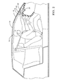
- Fig. 1 is a cut-away side view of a vehicle equipped with a windshield display system in accordance with one embodiment
- Fig. 2 is another cut-away side view of a vehicle equipped with a windshield display system in accordance with one embodiment
- Fig. 3 is a diagram of the windshield display system of Fig. 1 and 2 in accordance with one embodiment.
- Fig. 4 is a flowchart of a method of operating the windshield display system of Fig. 1 and 2 in accordance with one embodiment.
- Fig. 1 illustrates a non-limiting example of a windshield display system, hereafter the system 10.
- the system 10 is configured project an image onto a windshield 12 of a vehicle 14 so that the image projected can be observed by an operator 16 of the vehicle 14.
- the system 10 is also configured to detect an obstruction of light projected by the system 10, for example obstruction by a hand 18 ( Fig. 2 ) of the operator 16.
- some other object may redirect or reflect an undesirable amount of the light projected by a projection device 20 directly toward the operator 16.
- Fig. 3 illustrates a non-limiting example of the projection device 20.
- the projection device 20 may include a light source 22 operable to emit a light beam 24.
- the light source 22 preferably emits ultraviolet (UV) light, however it is recognized that a windshield display system could be devised that relies on a light source emitting light at wavelengths other than the UV band of wavelengths, infrared or visible wavelengths for example.
- the light source 22 may be a laser configured to emit ultraviolet (UV) light, for example a 405nm 250mW UV laser manufactured by Nichia Corporation located in Guangzhou,China , or a model RLTMDL-405-250-5 from Roither Laser Inc. located in Vienna, Austria.
- the projection device 20 may also include a scanning mirror 26, also known as a galvanometer mirror or a micro-electro-mechanical system (MEMS) mirror.
- the scanning mirror 26 is operable to reflect the light beam 24 from the light source 22 toward a desired location 28 on the windshield 12 and thereby define a light path 30 between the scanning mirror 26 and the desired location 28.
- a scanning mirror is any device capable of varying the angle of the mirror relative to the light source 22 and the windshield 12 such that the light beam 24 scans the windshield in a manner effective to 'draw' an image with the light beam 24.
- the scanning mirror 26 is able to vary the desired location 28 on the windshield 12 such that a person viewing the windshield 12 may see an image, assuming that the windshield is configured to display an image when so illuminated.
- a suitable scanning mirror is a 4-Quadrant (bi-directional) actuator model no. 7MM available from Mirrorcle Technologies, Inc. located in Richmond, California.
- the projection device 20 may also include a light detector 32 configured to detect the emitted light 34 that may be generated in response to the light beam 24 illuminating the desired location 28.
- the emitted light 34 is reflected toward the light detector 32 by the scanning mirror 26, and so emitted light 34 propagates from the desired location 28 to the scanning mirror 26 via the light path 30.
- the light source 22 and the light detector 32 are arranged in relatively close proximity to each other as part of the projection device 20.
- both the light beam 24 and the emitted light 34 are reflected off the scanning mirror 26 with the scanning mirror 26 at essentially the same position or orientation. Accordingly, the light beam and the emitted light 34 both travel the light path 30, i.e. the same path between the desired location 28 and the scanning mirror 26.
- a detection signal 36 does not need to include image information, as would a camera, but only needs to include an indication of the intensity of the emitted light 34.
- the detection signal 36 may advantageously include hue or saturation characteristics of the emitted light 34 so further analysis of the emitted light could be performed, other than image analysis.
- an image is understood to include a plurality of pixels possibly having varying levels of hue, saturation, and intensity across the image.
- the light detector 32 only needs to be able to detect a single pixel, or optically average the emitted light 34 emitted from the desired location 28.
- a suitable light detector is a Switchable Gain Photo Detector, part number PDA25K available from Thorlabs located in Newton, New Jersey.
- the projection device 20 may also include a controller 38 configured to determine when the light path 30 is obstructed based on the detection signal 36 from the light detector 32.
- the controller 38 may include a processor such as a microprocessor or other control circuitry as should be evident to those in the art.
- the controller 38 may include memory, including non-volatile memory, such as electrically erasable programmable read-only memory (EEPROM) for storing one or more routines, thresholds and captured data.
- EEPROM electrically erasable programmable read-only memory
- the one or more routines may be executed by the processor to perform steps for determining if signals received by the controller 38 for determining if the light path 30 is obstructed as described herein.
- the controller 38 may be configured to output a light source signal 40 to the light source 22 that may be effective to turn-on or turn-off the light source 22, or vary the intensity of the light beam 24. Since the controller 38 effectively determines at least the intensity of the light beam 24, and optionally, for example, the color or colors of the light beam 24, the controller 38 can expect what the intensity or other characteristics of the emitted light should be indicated by the detection signal 36. As will be explained in more detail below, with the system 10 configured as described herein, determining obstruction may be as simple as determining if the intensity indicated by the detection signal 36 is greater than or less than some threshold determined based on the light source signal 40. As such, the system 10 provides a simple way to turn-off the light source 22 when the light path 30 is obstructed. It should be appreciated that the controller 38 does not need to be configured to perform image analysis as would be the case if the light detector was replace by a camera that observed an area of the windshield 12 substantially larger than the desired location 28.
- the system 10 may advantageously include the windshield 12 being equipped with fluorescing material configured to generate emitted light when illuminated with UV light, for example a fluorescing coating 42.
- fluorescing material configured to generate emitted light when illuminated with UV light
- a fluorescing coating 42 is available from SuperImaging Inc. located in Fremont, California.
- the projection device 20 may also include a beam splitter 46 interposed between the light source 22 and the scanning mirror 26.
- the beam splitter 46 is oriented so that the emitted light 34 propagating along the light path 30 is directed into the light detector 32.
- the adjustment can be by way of adjusting the orientation of the beam splitter 46.
- this configuration generally allows for the projection device 20 to be installed in a variety of vehicle models having various orientations of windshields without further alignment of the system 10. This stands in marked contrast to systems that use cameras located remote from the light source 22 and so need to be calibrated for each different vehicle configuration (e.g. windshield angle) and camera location.
- the beam splitter 46 is generally configured to direct emitted light 34 emitted from the desired location 28, and reflected by the scanning mirror 26, toward the light detector 32.
- the beam splitter 46 it may be preferable for the beam splitter 46 to be configured to be more transmissive of the wavelength of the light beam 24, and more reflective of the wavelength of the emitted light 34.
- the beam splitter 46 is more transmissive of the wavelength of the emitted light 34, and more reflective of the wavelength of the light beam 24, then it may be preferable for the relative locations of the light source 22 and the light detector 32 shown in Fig. 3 to be exchanged.
- a suitable beam splitter is part number CMI-BS013 available from Thorlabs located in Newton, New Jersey.
- the scanning mirror 26 is a split scanning mirror configured to have two sections of mirror fixedly coupled so that the sections move together, and the two sections are not parallel. Then the light source 22 is oriented to direct the light beam 24 to one section of the scanning mirror 26, and the light detector 32 is oriented so the emitted light 34 is reflected by the other section of the scanning mirror to the light detector 32. Since the two sections of the scanning mirror 26 move together, the relative orientations of the light source 22 and the light detector 32 can remain fixed even though the desired location 28 moves about to form an image on the windshield 12.
- the light beam 24 and the emitted light 34 will not travel precisely the same light path 30, but will travel substantially the same path and only be separated by the distance between the two sections of split mirror at the scanning mirror end to the light path, and converge at the desired location 28.
- the projection device 20 may also include an optical bandpass filter 48 configured to generally pass light having a bandpass wavelength corresponding to an emitted light wavelength of the emitted light 34 (i.e. wavelength of the emitted light 34), and generally block light having a wavelength other than the bandpass wavelength.
- the optical bandpass filter 48 may be arranged to filter the emitted light 34 directed to or received by to the light detector 32. Including the optical bandpass filter 48 is advantageous because then the light detector 32 is less likely to include in the detection signal 36 contributions from light from other than that emitted by the fluorescing coating 42.
- the controller 38 may determine that the light path 30 is obstructed if the detection signal 36 indicates that an emitted light intensity of the emitted light 34 is less than a minimum intensity threshold. It should be appreciated that the minimum intensity threshold would likely be determined empirically, and could vary from vehicle model to vehicle model. It should also be appreciated that the minimum intensity threshold would vary if changes to the optical characteristics of the beam splitter 46 and/or the optical bandpass filter 48 were made.
- the controller 38 could also be configured to turn-off the light source 22 when the detection signal 36 indicates that the desired location 28 is being illuminated by excessive light from another source, for example the sun or headlights from an oncoming vehicle.
- the controller may determine that the desired location is being illuminated by excessive light from another source if the detection signal 36 indicates that an emitted light intensity is greater than a maximum intensity threshold.
- the maximum intensity threshold would typically be determined empirically for various vehicle models and possibly based on legislated regulations for windshield displays. It follows then that the controller may be configured to turn-off the light source 22 when the detection signal 36 indicates that the light path 30 is obstructed, or turn-off the light source 22 when the detection signal 36 indicates that the desired location 28 is being illuminated by excessive light from another source.
- Fig. 4 illustrates a non-limiting example of a method 400 of operating a windshield display system 10.
- the method 400 seeks to determine if the light path 30 is obstructed by any object by determining if the emitted light 34 detected by the light detector 32 corresponds to what was expected.
- Step 410 EMIT LIGHT BEAM
- Step 410 may include emitting a light beam 24 toward a desired location 28 on a windshield 12.
- Step 410 may also include operating the scanning mirror 26 to reflect the light beam 24 from the light source 22 to the desired location 28.
- a line between the scanning mirror 26 and the desired location 28 generally defines the light path 30.
- Step 420, DETECT EMITTED LIGHT may include detecting an emitted light 34 propagating in the light path 30. It should be understood that the emitted light 34 is not the only light generated in response to the light beam 24 illuminating the desired location 28 as the system 10 must also generate light that the operator 16 can see. But the portion of the emitted light that travel the light path 30 is what is detected by the system 10 to determine if an obstruction exists.
- Step 430 LIGHT PATH OBSTRUCTED?, may include determining when the light path 30 is obstructed based on an emitted light intensity of the emitted light 34 propagating in the light path 30
- step 430 may include determining that the emitted light intensity of the emitted light 34 is less than a minimum intensity threshold.
- the minimum intensity threshold is generally an empirically determined value and is expected to vary, for example, as ambient lighting conditions change, the angle of the windshield 12 changes, the fluorescing coating 42 changes due improvements in the materials forming the fluorescing coating 42, or as the fluorescing coating 42 ages.
- the method 400 may determine that an obstruction is occurring and proceed to step 450. If the emitted light intensity of the emitted light 34 is greater than a minimum intensity threshold, then it may be that no obstruction is present, and so the method 400 proceeds to step 440.
- Step 440 EXCESS ILLUMINATION?, may include determining when the desired location 28 is being illuminated by excessive light, possibly from another source or possibly because the light source 22 is emitting more light than expected, based on the emitted light intensity. For example, step 440 may include determining that an emitted light intensity is greater than a maximum intensity threshold. As described above, the maximum intensity threshold is generally an empirically determined value and is expected to vary, for example, as ambient lighting conditions change. If the emitted light intensity of the emitted light 34 is greater than a maximum intensity threshold, then the method 400 may determine that an excessive light is impinging on the windshield 12, and so proceed to step 450.
- step 410 may include stepping the scanning mirror to the next desired location or pixel so that an image can be formed on the windshield 12.
- Step 450, TURN-OFF LIGHT BEAM may include turning-off the light beam when the light path is obstructed, or turning-off the light beam when the desired location is being illuminated by excessive light from another source.
- the controller 38 may send a command to the light source 22 to emit no light, or if safety of an out of control light source is a concern, the controller 38 may be configured to interrupt electrical power to the light source by way of a means not illustrated, but known to those skilled in the art.
- a windshield display system 10 a controller 38 for the windshield display system 10 and a method 400 of operating a windshield display system is provided.
- the system is advantageous over systems present in the prior art in that the system 10 only 'looks' at the desired location 28, (i.e. point, pixel, or limited area) where the system 10 is illuminating the windshield 12 with a light detector 32, and so the complicated image processing algorithms required for camera based systems are avoided.
- the light source 22 and the light detector 32 are generally preassembled into the projection device 20 prior to installation into the vehicle 14, aligning the light source and light detector can be more easily performed in a stand-off type operation as opposed to having to align the system after it is installed into the vehicle 14.
Applications Claiming Priority (1)
| Application Number | Priority Date | Filing Date | Title |
|---|---|---|---|
| US13/563,778 US20140034806A1 (en) | 2012-08-01 | 2012-08-01 | Windshield display with obstruction detection |
Publications (1)
| Publication Number | Publication Date |
|---|---|
| EP2693256A1 true EP2693256A1 (fr) | 2014-02-05 |
Family
ID=48745732
Family Applications (1)
| Application Number | Title | Priority Date | Filing Date |
|---|---|---|---|
| EP13174130.8A Withdrawn EP2693256A1 (fr) | 2012-08-01 | 2013-06-27 | Affichage de pare-brise avec détection d'obstruction |
Country Status (2)
| Country | Link |
|---|---|
| US (1) | US20140034806A1 (fr) |
| EP (1) | EP2693256A1 (fr) |
Cited By (2)
| Publication number | Priority date | Publication date | Assignee | Title |
|---|---|---|---|---|
| WO2022238050A1 (fr) * | 2021-05-10 | 2022-11-17 | Bayerische Motoren Werke Aktiengesellschaft | Procédé et dispositif pour faire fonctionner un système d'affichage sur le pare-brise avec une détection d'affichage couverte, et système d'affichage sur le pare-brise |
| WO2023041211A1 (fr) * | 2021-09-15 | 2023-03-23 | Bayerische Motoren Werke Aktiengesellschaft | Système d'affichage par réflexion et procédé de fonctionnement d'un système d'affichage par réflexion avec détection de masquage |
Families Citing this family (5)
| Publication number | Priority date | Publication date | Assignee | Title |
|---|---|---|---|---|
| EP3274624B1 (fr) * | 2015-02-23 | 2020-10-28 | CoeLux S.r.l. | Système d'éclairage de siège |
| US10962764B2 (en) * | 2016-04-01 | 2021-03-30 | Intel Corporation | Laser projector and camera |
| FR3055946B1 (fr) * | 2016-09-15 | 2020-07-17 | Valeo Vision | Dispositif lumineux utilisant une source lumineuse de haute resolution |
| JP6265448B1 (ja) * | 2016-10-24 | 2018-01-24 | 株式会社 関西マサル | 防水シート施工用の自立型圧着治具 |
| CN110073273B (zh) * | 2016-12-12 | 2021-06-01 | 富士胶片株式会社 | 投影型显示装置、投影型显示装置的控制方法、存储介质 |
Citations (5)
| Publication number | Priority date | Publication date | Assignee | Title |
|---|---|---|---|---|
| EP0394072A2 (fr) * | 1989-04-20 | 1990-10-24 | Fujitsu Limited | Dispositif sélectif en rotation pour l'utilisation avec un dispositif de balayage optique |
| US20050035943A1 (en) * | 2003-07-09 | 2005-02-17 | Sony Corporation | Projection type image display apparatus |
| US20070008501A1 (en) * | 2005-07-07 | 2007-01-11 | Seiko Epson Corporation | Image display device and method of controlling image display device |
| EP2233962A2 (fr) * | 2009-03-27 | 2010-09-29 | Delphi Technologies, Inc. | Détection automatique des défauts et procédé d'arrêt de laser pour affichage d'essuie-glace généré par laser |
| US20120032875A1 (en) * | 2010-08-05 | 2012-02-09 | Microvision, Inc. | Scanned Image Projection System Employing Beam Folding Apparatus |
Family Cites Families (2)
| Publication number | Priority date | Publication date | Assignee | Title |
|---|---|---|---|---|
| US3690233A (en) * | 1970-07-29 | 1972-09-12 | Ltv Aerospace Corp | Photographing means |
| US20140036075A1 (en) * | 2012-07-31 | 2014-02-06 | Delphi Technologies, Inc. | Windshield display system |
-
2012
- 2012-08-01 US US13/563,778 patent/US20140034806A1/en not_active Abandoned
-
2013
- 2013-06-27 EP EP13174130.8A patent/EP2693256A1/fr not_active Withdrawn
Patent Citations (5)
| Publication number | Priority date | Publication date | Assignee | Title |
|---|---|---|---|---|
| EP0394072A2 (fr) * | 1989-04-20 | 1990-10-24 | Fujitsu Limited | Dispositif sélectif en rotation pour l'utilisation avec un dispositif de balayage optique |
| US20050035943A1 (en) * | 2003-07-09 | 2005-02-17 | Sony Corporation | Projection type image display apparatus |
| US20070008501A1 (en) * | 2005-07-07 | 2007-01-11 | Seiko Epson Corporation | Image display device and method of controlling image display device |
| EP2233962A2 (fr) * | 2009-03-27 | 2010-09-29 | Delphi Technologies, Inc. | Détection automatique des défauts et procédé d'arrêt de laser pour affichage d'essuie-glace généré par laser |
| US20120032875A1 (en) * | 2010-08-05 | 2012-02-09 | Microvision, Inc. | Scanned Image Projection System Employing Beam Folding Apparatus |
Cited By (2)
| Publication number | Priority date | Publication date | Assignee | Title |
|---|---|---|---|---|
| WO2022238050A1 (fr) * | 2021-05-10 | 2022-11-17 | Bayerische Motoren Werke Aktiengesellschaft | Procédé et dispositif pour faire fonctionner un système d'affichage sur le pare-brise avec une détection d'affichage couverte, et système d'affichage sur le pare-brise |
| WO2023041211A1 (fr) * | 2021-09-15 | 2023-03-23 | Bayerische Motoren Werke Aktiengesellschaft | Système d'affichage par réflexion et procédé de fonctionnement d'un système d'affichage par réflexion avec détection de masquage |
Also Published As
| Publication number | Publication date |
|---|---|
| US20140034806A1 (en) | 2014-02-06 |
Similar Documents
| Publication | Publication Date | Title |
|---|---|---|
| EP2693256A1 (fr) | Affichage de pare-brise avec détection d'obstruction | |
| JP6468482B2 (ja) | 撮像装置、物体検出装置及び移動体機器制御システム | |
| US9519841B2 (en) | Attached matter detector and vehicle equipment control apparatus | |
| US10464470B2 (en) | Vehicle lamp | |
| US9438871B2 (en) | Laser projection apparatus with bundled fibers | |
| KR101500399B1 (ko) | 리어 콤비네이션 램프 기능을 제공하는 곡면 디스플레이 장치 | |
| CN108302434A (zh) | 照明装置 | |
| EP3139585B1 (fr) | Ensemble intégré avec caméra, détection de lumière ambiante et capteur de pluie | |
| KR20110101177A (ko) | 차창의 상태를 검출하기 위한 카메라 장치 | |
| JP2004070298A (ja) | 画像投射装置及び画像投射方法 | |
| KR102221153B1 (ko) | 차량용 헤드램프 시스템 및 이의 제어 방법 | |
| CN105450947B (zh) | 车辆光学传感器系统 | |
| EP3228929A1 (fr) | Dispositif de phare de véhicule | |
| CN103197415A (zh) | 眼部保护装置及方法 | |
| EP2693253A1 (fr) | Système d'affichage de pare-brise | |
| WO2016084359A1 (fr) | Dispositif d'imagerie, détecteur d'objet, et système de commande de dispositif mobile | |
| JP5002268B2 (ja) | 防護域の監視装置 | |
| JP6268190B2 (ja) | カメラを用いたガラス面の雨滴検出のための照明 | |
| KR101917289B1 (ko) | 차량을 위한 카메라 시스템 | |
| US10451259B2 (en) | Headlight, vehicle with headlight and method for monitoring a headlight | |
| US20210166410A1 (en) | Distance measurement device | |
| US20190079283A1 (en) | Light module for emitting light and method for emitting visible and non-visible light | |
| JP2018146761A (ja) | 表示装置及び投影装置 | |
| KR20210055435A (ko) | 차량의 내부 감시용 카메라 시스템 | |
| US11195439B2 (en) | Head-up display apparatus |
Legal Events
| Date | Code | Title | Description |
|---|---|---|---|
| AK | Designated contracting states |
Kind code of ref document: A1 Designated state(s): AL AT BE BG CH CY CZ DE DK EE ES FI FR GB GR HR HU IE IS IT LI LT LU LV MC MK MT NL NO PL PT RO RS SE SI SK SM TR |
|
| AX | Request for extension of the european patent |
Extension state: BA ME |
|
| PUAI | Public reference made under article 153(3) epc to a published international application that has entered the european phase |
Free format text: ORIGINAL CODE: 0009012 |
|
| STAA | Information on the status of an ep patent application or granted ep patent |
Free format text: STATUS: THE APPLICATION IS DEEMED TO BE WITHDRAWN |
|
| 18D | Application deemed to be withdrawn |
Effective date: 20140806 |