EP2693073A1 - Rotary damper - Google Patents
Rotary damper Download PDFInfo
- Publication number
- EP2693073A1 EP2693073A1 EP11862327.1A EP11862327A EP2693073A1 EP 2693073 A1 EP2693073 A1 EP 2693073A1 EP 11862327 A EP11862327 A EP 11862327A EP 2693073 A1 EP2693073 A1 EP 2693073A1
- Authority
- EP
- European Patent Office
- Prior art keywords
- flow path
- rotor
- pressure
- check valve
- case
- Prior art date
- Legal status (The legal status is an assumption and is not a legal conclusion. Google has not performed a legal analysis and makes no representation as to the accuracy of the status listed.)
- Granted
Links
Images










Classifications
-
- F—MECHANICAL ENGINEERING; LIGHTING; HEATING; WEAPONS; BLASTING
- F16—ENGINEERING ELEMENTS AND UNITS; GENERAL MEASURES FOR PRODUCING AND MAINTAINING EFFECTIVE FUNCTIONING OF MACHINES OR INSTALLATIONS; THERMAL INSULATION IN GENERAL
- F16F—SPRINGS; SHOCK-ABSORBERS; MEANS FOR DAMPING VIBRATION
- F16F9/00—Springs, vibration-dampers, shock-absorbers, or similarly-constructed movement-dampers using a fluid or the equivalent as damping medium
- F16F9/10—Springs, vibration-dampers, shock-absorbers, or similarly-constructed movement-dampers using a fluid or the equivalent as damping medium using liquid only; using a fluid of which the nature is immaterial
- F16F9/14—Devices with one or more members, e.g. pistons, vanes, moving to and fro in chambers and using throttling effect
- F16F9/145—Devices with one or more members, e.g. pistons, vanes, moving to and fro in chambers and using throttling effect involving only rotary movement of the effective parts
-
- B—PERFORMING OPERATIONS; TRANSPORTING
- B60—VEHICLES IN GENERAL
- B60N—SEATS SPECIALLY ADAPTED FOR VEHICLES; VEHICLE PASSENGER ACCOMMODATION NOT OTHERWISE PROVIDED FOR
- B60N2/00—Seats specially adapted for vehicles; Arrangement or mounting of seats in vehicles
- B60N2/02—Seats specially adapted for vehicles; Arrangement or mounting of seats in vehicles the seat or part thereof being movable, e.g. adjustable
- B60N2/22—Seats specially adapted for vehicles; Arrangement or mounting of seats in vehicles the seat or part thereof being movable, e.g. adjustable the back-rest being adjustable
-
- B—PERFORMING OPERATIONS; TRANSPORTING
- B60—VEHICLES IN GENERAL
- B60N—SEATS SPECIALLY ADAPTED FOR VEHICLES; VEHICLE PASSENGER ACCOMMODATION NOT OTHERWISE PROVIDED FOR
- B60N2/00—Seats specially adapted for vehicles; Arrangement or mounting of seats in vehicles
- B60N2/02—Seats specially adapted for vehicles; Arrangement or mounting of seats in vehicles the seat or part thereof being movable, e.g. adjustable
- B60N2/22—Seats specially adapted for vehicles; Arrangement or mounting of seats in vehicles the seat or part thereof being movable, e.g. adjustable the back-rest being adjustable
- B60N2/2227—Seats specially adapted for vehicles; Arrangement or mounting of seats in vehicles the seat or part thereof being movable, e.g. adjustable the back-rest being adjustable and provided with braking systems
-
- B—PERFORMING OPERATIONS; TRANSPORTING
- B60—VEHICLES IN GENERAL
- B60N—SEATS SPECIALLY ADAPTED FOR VEHICLES; VEHICLE PASSENGER ACCOMMODATION NOT OTHERWISE PROVIDED FOR
- B60N2/00—Seats specially adapted for vehicles; Arrangement or mounting of seats in vehicles
- B60N2/90—Details or parts not otherwise provided for
- B60N2/919—Positioning and locking mechanisms
- B60N2/933—Positioning and locking mechanisms rotatable
- B60N2/938—Positioning and locking mechanisms rotatable and provided with braking systems
Definitions
- the present invention relates to a rotary damper, and particularly to structure that is suitable for a unidirectional rotary damper.
- Patent Document 1 discloses a unidirectional rotary damper, which is simple in structure and can be produced at low cost.
- the rotary damper described in the Patent Document 1 comprises: a case having a cylindrical chamber; a rotor (i.e. rotating body) having a rotor body of a cylindrical shape and vanes, the rotor being housed in the cylindrical chamber such that its rotation axis coincides with the center line of the cylindrical chamber, to allow rotation of the rotor; viscous fluid filling the cylindrical chamber; and a lid for enclosing the rotor and the viscous fluid in the cylindrical chamber.
- a rotor i.e. rotating body
- a rotor body of a cylindrical shape and vanes the rotor being housed in the cylindrical chamber such that its rotation axis coincides with the center line of the cylindrical chamber, to allow rotation of the rotor
- viscous fluid filling the cylindrical chamber
- a lid for enclosing the rotor and the viscous fluid in the cylindrical chamber.
- In the inner wall surface of the cylindrical chamber there are formed bulkheads, which are projecting toward the center line
- Each vane protruding from the outer periphery of the rotor body toward the inner periphery side of the cylindrical chamber is formed, so as to form a narrow gap between the vane and the inner periphery of the cylindrical chamber.
- a flow path from one side surface (referred to as first side surface) perpendicular to the direction of rotation of the rotor to the other side surface (referred to as second side surface).
- an apical surface (a surface opposite to the inner wall surface of the cylindrical chamber) of each vane is attached with a seal member to close the gap between the apical surface and the inner wall surface of the cylindrical chamber.
- Each seal member has a check valve of an elastic body, which opens and closes the flow path from the side of the second side surface with respect to the direction of rotation of the vane.
- the rotary damper described in the Patent Document 1 blocks the flow paths by check valves pressed against the second side surfaces of the vanes because of the viscous fluid in the cylindrical chamber, when force for rotating in the direction from the first side surfaces of the vanes toward the second side surfaces of the vanes (i.e. in the normal rotation direction) is applied to the rotor.
- the movement of the viscous fluid is limited to movement through the narrow gap between each bulkhead of the cylindrical chamber and the outer periphery of the rotor body.
- the pressure on the viscous fluid at the sides of the second side surfaces of the vanes increases, whereby strong damping torque is generated.
- the rotary damper described in the Patent Document 1 can be damaged when pressure of the viscous fluid on the sides of the second side surface of the vanes increases above the assumed value because of force being applied to the rotor rotating in the normal rotation direction above the assumed rotating speed.
- the present invention has been made considering the above circumstances. And an object of the present invention is to provide a technique that can reduce the possibility of breakage of a rotary damper even if rotating force above the assumed value is applied to the rotary damper.
- the present invention provides a rotary damper for generating damping torque against applied rotating force by restricting movement of filled viscous fluid, comprising a means for canceling the restriction of movement when the rotating force is larger than a predetermined value.
- the present invention provides a rotary damper for generating damping torque against applied rotating force by restricting movement of filled viscous fluid, comprising a pressure-regulating valve which opens for canceling the restriction of movement of the viscous fluid, when the rotating force is more than or equal to a predetermined value.
- the present invention even if rotating force larger than an assumption is applied, it is possible to suppress the pressure less than the predetermined value on the viscous fluid filling the cylindrical chamber, so that the possibility of damage of the rotary damper can be reduced.
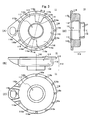
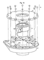
- Figs. 1(A) and 1(B) are an external view and a partial cross-section showing a schematic construction of the rotary damper 1 of the first embodiment of the present invention.
- Fig. 2 is an exploded view of the rotary damper 1.
- the rotary damper 1 of the present embodiment comprises: the case 11; the rotor (rotating body) 12 housed in the case 11 so as to be rotatable relatively to the case 11; the viscous fluid (such as oil, silicone or the like) 13 filling the case 11; the lid 14 for enclosing the rotor 12 together with the viscous fluid 13 in the case 11; and a plurality of the screws 18 for fixing the lid 14 to the case 11.
- the rotary damper 1 further comprises the check valves 15 and the pressure-regulating valves 16.
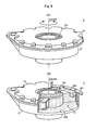
- Figs. 3(A) - 3(C) are a top view, a front elevation and a bottom view of the case 11.
- Fig. 3(D) is an A-A cross-section of the case 11 shown in Fig. 3(A) .
- the case 11 comprises: the case body 112; and the flange portion 118 formed on the outer periphery of the edge portion of the case body 112.
- the cylindrical chamber i.e. the cylindrical shape space having the bottom
- the rotor 12 has the rotor body 131 of the cylindrical shape and the vanes 124a, 124b formed on the outer periphery 122 of the rotor body 131.
- the rotor 12 is housed in the cylindrical chamber 111 such that the rotor 12 can rotate on the center line 110 of the cylindrical chamber 111 (i.e. such that the center line 110 of the cylindrical chamber 111 coincides with the rotation axis 120 of the rotor 12).
- On the inner periphery 113 of the case body 112 i.e.
- the pair of projecting bulkheads 115a, 115b are formed along the center line 110 of the cylindrical chamber 111.
- the pair of bulkheads 115a, 115b protrude toward the outer periphery 122 of the rotor body 131 (i.e. the apical surfaces 114 of the projecting bulkheads 115a, 115b are close to the outer periphery 122 of the rotor 12), so as to partition in radial directions the ring-shaped space between the outer periphery 122 of the rotor body 131 and the sidewall surface 113 of the cylindrical chamber 111.
- the viscous fluid 13 fills the areas (the areas 111a - 111d in Fig.
- the plurality of threaded holes 118a are formed in the flange portion 118. And, the screws 18 are inserted through through-holes 143a of the lid 14 placed on the flange portion 118, and fastened into these threaded holes 118a.
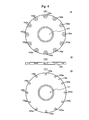
- Figs. 4(A) - 4(C) are a top view, a front elevation and a bottom view of the lid 14.
- the opening 141 for inserting the other end portion (the upper end portion 129b) of the rotor body 131 is formed at a corresponding position of the opening 117 of the bottom surface 116.
- the through-holes 143a for inserting the screws 18 fastened into the threaded holes 118a are formed at corresponding positions of the threaded holes 118a.
- a seal member such as an O-ring may be interposed between the lid 14 and the case 11 to increase the sealing performance, so that the viscous fluid 13 will not leak out of the cylindrical chamber 111.
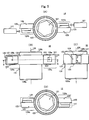
- Figs. 5(A) - 5(D) are a top view, a front elevation, a side elevation and a bottom view of the rotor 12.
- the through-hole 121 centering on the rotation axis 120 is formed.
- the through-hole 121 is for inserting a shaft (not shown) which transmits rotating force from the outside to the rotor 12.
- the lower end portion 129a of the rotor body 131 (the through-hole 121) is slidably inserted into the opening 117 formed in the bottom surface 116 of the cylindrical chamber 111 of the case 11.
- the upper end portion 129b of the rotor body 131 (the through-hole 121) is slidably inserted into the opening 141 of the lid 14.
- seal members such as O-rings may be interposed between the end portions 129a, 129b of the rotor body 131 and the openings 117,141 to increase the sealing performance, so that the viscous fluid 13 will not leak out of the cylindrical chamber 111.
- the pair of vanes (rotating wings) 124a, 124b are formed along the sidewall surface 113 of the cylindrical chamber 111.
- the pair of vanes 124a, 124b protrude toward the sidewall surface 113 of the cylindrical chamber 111 so that the apical surfaces (i.e. the surfaces corresponding to the sidewall surface 113 of the cylindrical chamber 111) 123 of the vanes 124a, 124b are close to the sidewall surface 113 of the cylindrical chamber 111.
- the lip seal 127 See Fig. 2 ) is attached.
- the lip seal 127 fills gaps formed between the apical surface 123 of the vane 124a, 124b and the sidewall surface 113 of the cylindrical chamber 111, gaps formed between the lower surface (the surface corresponding to the bottom surface 116 of the cylindrical chamber 111) 125 of the vane 124a, 124b and the bottom surface 116 of the cylindrical chamber 111, and gaps formed between the upper surface (the surface on the side of the lid 14) 126 of the vane 124a, 124b and the lower surface (the surface on the side of the case 11) 142 of the lid 14.
- Fig. 6(A) is a B-B cross-section of the rotor 12 shown in Fig. 5(B) .
- Fig. 6(B) is an enlarged view of the portion C of Fig. 5(A) .
- the flow path (an orifice) 128a is formed to pass through the one side surface 132a and the other side surface 133b of this vane 124a.
- the flow path 128a connects the area 111a (See Fig. 7 ) and the area 111b (See Fig. 7 ) of the cylindrical chamber 111.
- the area 111a is partitioned by this vane 124a and the bulkhead 115a of the cylindrical chamber 111.
- the area 111b (See Fig. 7 ) is partitioned by this vane 124a and the bulkhead 115b of the cylindrical chamber 111.
- the flow path 128b is formed to pass through one side surface 132b and the other side surface 133b of this vane 124b.
- the pass through connects the area 111c (See Fig. 7 ) and the area 111d (See Fig. 7 ) of the cylindrical chamber 111.
- the area 111c is partitioned by the vane 124b and the bulkhead 115a of the cylindrical chamber 111.
- the area 111d is partitioned by the vane 124b and the bulkhead 115b of the cylindrical chamber 111.
- Each of the flow paths 128a, 128b is provided in its inside with the check valve 15 and the pressure-regulating valve 16 as a pair.
- each flow path 128a, 128b three adjacent sections 1280 - 1282 are formed between the flow path opening 1284 and the flow path opening 1285 such that the axes of these sections are shifted from the axis of the flow path openings 1284, 1285.
- the flow path opening 1284 is formed in the one side surface 132a, 132b of the vane 124a, 124b.
- the flow path opening 1285 is formed in the other side surface 133a, 133b of the vane 124a, 124b.
- Each of these three sections has a flow path cross-section sizes in the radial direction larger than that of the flow path openings 1284, 1285.
- first flow path section 1280 the second flow path section 1281 whose flow path cross-section size in the radial direction is larger than that of the first flow path section 1280.
- third flow path section 1282 whose flow path cross-section size in the radial direction is smaller than that of the second flow path section 1281.
- the second flow path section 1281 houses the check valve 15 slidably in the flow direction of the viscous fluid 13.
- the third flow path section 1282 houses the pressure-regulating valve 16.
- the second flow path section 1281 is formed so as to adjoin the side of the area 111a, 111d (See Fig. 7 ) to the third flow path section 1282, wherein the filled viscous fluid 13 in the area 111a, 111d is pressurized when the rotor 12 is rotated in the normal rotation direction (the direction ⁇ in the present embodiment).
- the check valve 15 is a plate-like member placed inside the second flow path section 1281 so as to open and close the second flow path section 1281, and slides within the second flow path section 1281 in directions that depend on the rotation direction of the rotor 12. Further, in the check valve 15, the through-hole 151 through which the viscous fluid 13 passes is formed. This through-hole 151 is opened and closed by the pressure-regulating valve 16.
- the pressure-regulating valve 16 comprises: the needle 160 for regulating the flow rate of the viscous fluid 13 passing through the through-hole 151 of the check valve 15; and the elastic body 162 such as a spring, which biases the needle 160 toward the second flow path section 1281.
- the needle 160 comprises: the tapered plug portion 161 for blocking the through-hole 151 of the check valve 15; and the rod-like stopper 163 provided at the end portion of the plug portion 161 on the side of the check valve 15.
- the needle 160 is inserted in the through-hole 151 of the check valve 15 from the side of the third flow path section 1282 so that the stopper 163 protrudes toward the second flow path section 1281.
- the plug portion 161 When the check valve 15 moves toward the third flow path section 1282, the plug portion 161 is inserted in the through-hole 151 of the check valve 15. As a result, the through-hole 151 of the check valve 15 is blocked by the plug portion 161. Further, when the needle 160 moves toward the first and second flow path sections 1280, 1281 by being biased by the elastic body 162, the stopper 163 abuts against the inner wall 1283 of the flow path 128a, 128b via the through-hole 151 of the check valve 15. As a result, the movement of the plug portion 161 toward the first and second flow path sections 1280 and 1281 is limited.
- the flow path 128a, 128b as described above can be prepared by: previously forming the through-hole 1288 in the vane 124a, 124b, as a part (i.e. the flow path opening 1284 on one side and the first and second flow path sections 1280 and 1281) of the flow path 128a, 128b; inserting the check valve 15 and the pressure-regulating valve 16 in this order into the through-hole 1288; and then fitting the block 1289 in the through-hole 1288, wherein a part (i.e. the other flow path opening 1285 and the third flow path section 1282) of the flow path 128a, 128b is formed in the block 1289.
- a part i.e. the other flow path opening 1285 and the third flow path section 1282
- guides for example, three or more protrusions formed on the end surface portion of the through-hole 151 on the side of the first flow path section 1280 for preventing play of the stopper 163 in the radial direction of the through-hole 151 of the check valve 15.
- FIGs. 7(A) and 7(B) and Fig. 8 are views for explaining the operating principle of the rotary damper 1.
- the viscous fluid 13 moves from the areas 111a, 111d to the areas 111b, 111c through the flow paths 128a, 128b.
- the plug portion 161 of the needle 160 is not pushed in the through-hole 151 of the check valve 15. And thereby the flow path 128a, 128b is opened. Accordingly, the viscous fluid 13 moves from the area 111b, 111c to the area 111a, 111d through the flow path 128a, 128b. Thus, the pressures of the viscous fluid 13 in the areas 111b, 111c are not increased. And thereby weak damping torque is generated.
- the rotary damper 1 generates strong damping torque against the rotating force of the normal rotation direction applied to the rotor 12 or the case 11, by limiting the movement of the viscous fluid 13 filling the inside of the cylindrical chamber 111 through the flow paths 128a, 128b.
- the rotary damper 1 is provided with the pressure-regulating valves 16 which cancel the limitation of the movement of the viscous fluid 13 from the high-pressure side to the low-pressure side when the rotating force exceeds the predetermined value.
- the pressure of the viscous fluid 13 filling the inside of the cylindrical chamber 111 can be kept below the predetermined value, reducing the possibility that the rotary damper 1 is damaged.
- the vane 124a of the rotor 12 is provided with the flow path 128a which connects the areas 111a, 111b partitioned by the bulkheads 115a, 115b of the cylindrical chamber 111 and this vane 124a.
- the vane 124b of the rotor 12 is provided with the flow path 128b which connects the areas 111c, 111d partitioned by the bulkheads 115a, 115b of the cylindrical chamber 111 and this vane 124b. Since the check valve 15 and the pressure-regulating valve 16 have the above-described construction, each of the flow paths 128a, 128b have the check valve 15 and the pressure-regulating valve 16 as a pair in its inside. Thus, according to the present embodiment, the check valve 15 and the pressure-regulating valve 16 are placed in the common flow path 128a, 128b not in respective different flow paths, making it possible to reduce the size of the rotary damper 1.
- the flow path 128a, 128b is formed in the vane 124a, 124b of the rotor 12. And the check valve 15 and the pressure-regulating valve 16 are provided as a pair in each of the flow paths 128a, 128b.
- the present invention is not limited to this.
- Figs. 9(A) and 9(B) are an external view and a partial cross-section showing a schematic construction of the rotary damper 2 according to the second embodiment of the present invention.
- Fig. 10 is an exploded view of the rotary damper 2.
- the rotary damper 2 of the present embodiment comprises: the case 21; the rotor (the rotating body) 12a housed in the case 21 so as to be rotatable relatively to the case 21; the viscous fluid 13 filling the case 21; the lid 14 for enclosing the rotor 12a together with the viscous fluid 13 in the case 21; the pair of backflow prevention mechanisms 22a, 22b each of which has the pressure-regulating function; and the plurality of screws 18 for fixing the lid 14 to the case 21.
- the viscous fluid 13, the screws 18 and the lid 14 are similar to those used in the rotary damper 1 of the first embodiment.
- the construction of the rotor 12a is similar to that of the rotor 12 used in the rotary damper 1 of the first embodiment except that the flow paths 128a, 128b are not formed in the vanes 124a, 124b. Accordingly, description of these will be omitted in the following.
- Figs. 11(A) - 11(C) are a top view, a front elevation and a bottom view of the case 21.
- Fig. 11(D) is a D-D cross-section of the case 21 shown in Fig. 11(A) .
- the case 21 comprises: the case body 212; and the flange portion 218 formed on the outer periphery of the edge portion of the case body 212.
- the cylindrical chamber i.e. the cylindrical shape space having the bottom
- the rotor 12a has the rotor body 131 of the cylindrical shape, and the vanes 124a, 124b formed on the outer periphery 122 of the rotor body 131.
- the rotor 12a is housed in the cylindrical chamber 211 such that the rotor 12a can rotate on the center line 210 of the cylindrical chamber 211 (i.e. such that the center line 210 of the cylindrical chamber 211 coincides with the rotation axis 220 of the rotor 12a).
- the opening 217 for inserting the one end portion (the lower end portion) 129a of the rotor 12a is formed in the bottom surface 216 of the cylindrical chamber 211.
- the pair of projecting bulkheads 215a, 215b are formed along the center line 210 of the cylindrical chamber 211.
- the projecting bulkheads 215a, 215b protrude toward the outer periphery 122 of the rotor body 131 (i.e. the apical surfaces 114 of the projecting bulkheads 215a, 215b are close to the outer periphery 122 of the rotor 12), so as to partition in radial directions the ring-shaped space between the outer periphery 122 of the rotor body 131 and the sidewall surface 213 of the cylindrical chamber 211.
- the viscous fluid 13 fills the areas (the areas 211a - 211d in Fig. 13 ) partitioned by these bulkheads 215a, 215b between the outer periphery 122 of the rotor body 131 and the sidewall surface 213 of the cylindrical chamber 211.
- the groove-like flow path 228a is formed in the bulkhead 215a.
- the groove-like flow path 228a connects the area 211a (See Fig. 13 ) in the cylindrical chamber 211 and the area 211c (See Fig. 13 ) in the cylindrical chamber 211.
- the area 211a is formed by the bulkhead 215a and the vane 124a of the rotor 12a.
- the area 211c is formed by the bulkhead 215a and the vane 124b of the rotor 12a.
- This flow path 228a houses slidably the backflow prevention mechanism 22a with pressure-regulating function.
- the flow path 228b is formed in the bulkhead 215b.
- the flow path 228b connects the area 211d (See Fig. 13 ) in the cylindrical chamber 211 and the area 211b (See Fig. 13 ) in the cylindrical chamber 211.
- the area 211d is formed by the bulkhead 215b and the vane 124b of the rotor 12a.
- the area 211b is formed by the bulkhead 215b and the vane 124a of the rotor 12a.
- This flow path 228b houses slidably the backflow prevention mechanism 22b with pressure-regulating function.
- the projecting portion 219 is formed in each of the flow paths 228a, the 228b.
- the projecting portion 219 narrows the width of a part of the flow path in the radial direction to limit the sliding range of the backflow prevention mechanism 22a, 22b with pressure-regulating function.
- the plurality of threaded holes 218a are formed. And the screws 18 are inserted through through-holes 143a of the lid 14 placed on the flange portion 118, and fastened into these threaded holes 218a.
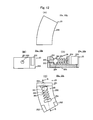
- Figs. 12(A) - 12(C) are a top view, a front elevation and a bottom view of the backflow prevention mechanism 22a, 22b with pressure-regulating function.
- Fig. 12(D) is an E-E cross-section of the backflow prevention mechanism 22a, 22b with pressure-regulating function shown in Fig. 12(C) .
- the backflow prevention mechanism 22a, 22b has the check valve 25 and the pressure-regulating valve 26.
- the check valve 25 comprises: the plate-like valve portion 251 which slides in the circumferential direction to open and close the one flow path opening (i.e. the flow path opening 229a, 229b (See Fig. 13 ) on the side of the area 211a, 211d in which the filled viscous fluid 13 is pressurized, when the rotor 12a is rotated in the normal rotation direction (the direction ⁇ (See Fig. 13 ) in the present embodiment)); the stoppers 252 which limit the sliding range of the valve portion 251 in cooperation with the projecting portion 219 in the flow path 228a, 228b; the holding portion 254 which holds the pressure-regulating valve 26; and the connecting portion 255 which connects the valve portion 251, the stoppers 252 and the holding portion 254.
- the plate-like valve portion 251 which slides in the circumferential direction to open and close the one flow path opening (i.e. the flow path opening 229a, 229b (See Fig. 13 ) on the side of the area 211a,
- the through-hole 253 which is opened and closed by the pressure-regulating valve 26 is formed.
- the holding portion 254 and the stoppers 252 are formed so as to be located on the side of the area 211b, 211c (See Fig. 13 ) in which the pressure of the filled viscous fluid 13 is reduced when the rotor 12a is rotated in the normal rotation direction (the direction ⁇ (See Fig. 13 ) in the present invention).
- the connecting portion 255 has such a length that the valve portion 251 is at a given distance away from the flow path opening 229a, 229b of the flow path 228a, 228b when the rotor 12a rotates in the reverse rotation direction (the direction ⁇ (See Fig. 14 ) in the present embodiment) and the stoppers 252 abut against the projecting portions 219 in the bulkhead 215a, 215b.
- the pressure-regulating valve 26 comprises: the needle 264 for regulating the flow rate of the viscous fluid 13 passing through the through-hole 253 of the valve portion 251 of the check valve 25; and the elastic body 262 such as a spring, which is fixed at one end to the holding portion 254 of the check valve 25 and biases at the other end the needle 264 toward the area 211b, 211c.
- the needle 264 comprises: the tapered plug portion 261 for blocking the through-hole 253 of the valve portion 251 of the check valve 25; and the rod-like guide 263 provided at the end portion of the plug portion 261 on the side of the valve portion 251.
- the guide 263 is inserted in the through-hole 253 of the valve portion 251 from the side of the area 211b, 211c, and guides the plug portion 261 into the through-hole 253 of the valve portion 251 of the check valve 25.
- the needle 264 moves toward the valve portion 251 of the check valve 25 due to biasing by the elastic body 262
- the plug portion 261 is inserted into the through-hole 253 of the valve portion, being guided by the guide 263.
- the through-hole 253 of the valve portion 251 of the check valve 25 is blocked by the plug portion 261.
- FIGs. 13(A) and 13(B) and Fig. 14 are view for explaining the operating principle of the rotary damper 2.
- the viscous fluid 13 moves from the area 211b, 211c to the area 211a, 211d through the flow path 228a, 228b.
- the pressures of the viscous fluid in the areas 211b, 211c are not increased. And thereby weak damping torque is generated.
- the pressure on the viscous fluid 13 filling the inside of the cylindrical chamber 211 can be kept below a predetermined value, reducing the possibility that the rotary damper 2 is damaged.
- the pressure-regulating valve 26 is incorporated in the check valve 25 to obtain the backflow prevention mechanism 22a, 22b with pressure-regulating function, the check valve 25 and the pressure-regulating valve 26 can be placed in the common flow path 228a, 228b, making it possible to reduce the size of the rotary damper 2.
- the flow paths 228a, 228b are formed in the bulkheads 215a, 215b of the cylindrical chamber 211, and the backflow prevention mechanisms 22a, 22b with pressure-regulating function are provided in the flow paths 228a, 228b.
- the present invention is not limited to this.
- Figs. 15(A) and 15(B) are external view and a partial cross-section showing a schematic construction of the rotary damper 3 according to the third embodiment of the present invention.
- Fig. 16 is an exploded view of the rotary damper 3.
- the rotary damper 3 of the present embodiment comprises: the case 31; the rotor (the rotating body) 32 housed in the case 31 so as to be rotatable relatively to the case 31; the viscous fluid 13 filling the case 31; the lid 14 for enclosing the rotor 32 together with the viscous fluid 13 in the case 31; and the plurality of screws 18 for fixing the lid 14 to the case 11.
- the rotary damper 3 further comprises the check valves 35 and the pressure-regulating valves 36.
- the viscous fluid 13, the screws 18 and the lid 14 are similar to those used in the rotary damper 1 of the first embodiment, and thus description of these will be omitted in the following.
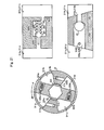
- Figs. 17(A) - 17(C) are a top view, a front elevation and a bottom view of the case 31.
- Fig. 17(D) is an F-F cross-section of the case 31 shown in Fig. 17(A) .
- the case 31 comprises: the case body 312; and the flange portion 318 formed on the outer periphery of the edge portion of the case body 312.
- the cylindrical chamber i.e. the space of the cylindrical shape having the bottom
- the rotor 32 has the rotor body 331 of the cylindrical shape and the vanes 324a, 324b formed on the outer periphery 322 of the rotor body 331.
- the rotor 32 is housed in the cylindrical chamber 311 such that the rotor 32 can rotate on the center line 310 of the cylindrical chamber 311 (i.e. such that the center line 310 of the cylindrical chamber 311 coincides with the rotation axis 320 of the rotor 32).
- On the inner periphery 313 of the case body 312 i.e.
- the pair of projecting bulkheads 315a, 315b are formed along the center line 310 of the cylindrical chamber 311.
- the projecting bulkheads 315a, 315b protrude toward the outer periphery 322 of the rotor body 331 (i.e. the apical surfaces 314 of the projecting bulkheads 315a, 315b are close to the side surface 322 of the rotor 32), so as to partition in radial directions the ring-shaped space between the outer periphery 322 of the rotor body 331 and the sidewall surface 313 of the cylindrical chamber 311.
- the viscous fluid 13 fills the areas (the areas 311a - 311d in Fig.
- the flow path (the orifice) 338a for check valve is formed in the bulkhead 315a.
- the flow path 338a connects the area 311a (See Fig. 22 ) and the area 311c (See Fig. 22 ).
- the area 311a is formed by this bulkhead 315a and the vane 324a of the rotor 32 in the cylindrical chamber 311.
- the area 311c (See Fig. 22 ) is formed by this bulkhead 315a and the vane 324b of the rotor 32 in the cylindrical chamber 311.
- the flow path (the orifice) 338b for check valve is formed in the other bulkhead 315b.
- the flow path 338b connects the area 311b (See Fig.
- the area 311b is formed by this bulkhead 315b and the vane 324a of the rotor 32 in the cylindrical chamber 311.
- the area 311d is formed by this bulkhead 315b and the vane 324b of the rotor 32 in the cylindrical chamber 311.
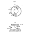
- Fig. 18(A) is a G-G cross-section of the case 31 shown in Fig. 17(B) .
- Fig. 18(B) is an enlarged view of the portion H of Fig. 18(A) .
- the spherical check valve 35 is provided in the inside of each of the flow paths 338a, 338b for check valve.
- the second flow path section 3382 for check valve has a flow path cross-section size in the radial direction larger than that of the first flow path section 3381 for check valve.
- the second flow path section 3382 for check valve has a diameter larger than that of the check valve 35.
- the second flow path section 3382 houses the check valve 35 slidably so that the check valve 35 opens and closes the first flow path section 3381 for check valve. Further, in the second flow path section 3382 for check valve, the stopper 3383 for limiting the sliding range of the check valve 35 is formed.
- the first flow path section 3381 for check valve is formed so as to be adjacent to the side of the area 311b, 311c in which the pressure of the filled viscous fluid 13 is reduced when the rotor 32 is rotated in the normal rotation direction (the direction ⁇ in the present embodiment, See Fig. 22 ).
- Figs. 19(A) - 19(D) are a top view, a front elevation, a side elevation and a bottom view of the rotor 32.
- the through-hole 321 centering on the rotation axis 320 is formed.
- the through-hole 321 inserts a shaft (not shown) that transmits the rotating force from the outside to the rotor 32.
- the lower end portion 329a of the rotor body 331 (the through-hole 321) is slidably inserted into the opening 317 formed in the bottom surface 316 of the cylindrical chamber 311 of the case 31.
- the upper end portion 329b of the rotor body 331 (the through-hole 321) is slidably inserted into the opening 141 of the lid 14.
- seal members such as O-rings may be interposed between the end portions 329a, 329b of the rotor body 331 and the openings 317, 141 to increase the sealing performance, so that the viscous fluid 13 will not leak out of the cylindrical chamber 311.
- the pair of vanes (rotating wings) 324a, 324b are formed along the rotation axis 320 of the rotor 32.
- the vanes 324a, 324b protrude toward the sidewall surface 313 of the cylindrical chamber 311 such that apical surfaces (i.e. the surfaces corresponding to the side wall surface 313 of the cylindrical chamber 311) 323 of the vanes 324a, 324b are close to the sidewall surface 313 of the cylindrical chamber 311.
- the lip seal 327 (See Fig. 15 ) is attached to each of the vanes 324a, 324b.
- the lip seal 327 fills gaps formed between the apical surface 323 of the vane 324a, 324b and the sidewall surface 313 of the cylindrical chamber 311, and gaps formed between the lower surface (the surface corresponding to the bottom surface 316 of the cylindrical chamber 311) 325 of the vane 324a, 324b and the bottom surface 316 of the cylindrical chamber 311. And also the lip seal 327 fills gaps formed between the upper surface (the surface on the side of the lid 14) 326 of the vane 324a, 324b and the lower surface 142 of the lid 14.
- Fig. 20(A) is an I-I cross-section of the rotor 32 shown in Fig. 19(B) .
- Fig. 20(B) is an enlarged view of the portion J of Fig. 20(A) .
- Fig. 20(C) is a view for explaining a method of preparing the flow paths 328a, 328b.
- the flow path (the orifice) 328a for pressure-regulating valve is formed.
- the flow path 328a for pressure-regulating valve connects the area 311a (See Fig. 22 ) in the cylindrical chamber 311 and the area 311b (See Fig. 22 ) in the cylindrical chamber 311.
- the area 311a is formed by the vane 324a and the bulkhead 315a of the cylindrical chamber 311.
- the area 311b is formed by the vane 324a and the bulkhead 315b of the cylindrical chamber 311.
- the flow path (the orifice) 328b for pressure-regulating valve is formed in the other vane 324b.
- the flow path 328b for pressure-regulating valve connects the area 311c (See Fig.
- the area 311c is formed by the vane 324b and the bulkhead 315a of the cylindrical chamber 311.
- the area 311d is formed by the vane 324b and the bulkhead 315b of the cylindrical chamber 311.
- the flow path section 3282 for pressure-regulating valve is formed between the flow path opening 3280 formed in the one side surface 332a, 332b of the vane 324a, 324b and the flow path opening 3281 formed in the other side surface 333a, 333b of the vane 324a, 324b.
- the flow path section 3282 for pressure-regulating valve has a flow path cross-section size in the radial direction larger than those of the flow path openings 3280, 3281.
- the axis of the flow path section 3282 for pressure-regulating valve is shifted from the axes of the flow path openings 3280, 3281.
- the flow path section 3282 for pressure-regulating valve houses the pressure-regulating valve 36.
- the pressure-regulating valve 36 comprises: the needle 360 for regulating the flow rate of the viscous fluid 13 passing through the flow path opening 3280 of the flow path 328a, 328b for pressure-regulating valve; and the elastic body 362 such as a spring, which presses the needle 360 toward the flow path opening 3280 of the flow path 328a, 328b for pressure-regulating valve.
- the flow path opening 3280 of the flow path 328a, 328b for pressure-regulating valve is the flow path opening facing the area 311a, 311b (See Fig. 22 ).
- the filled viscous fluid 13 in the area 311a, 311b is pressurized when the rotor 32 is rotated in the normal rotation direction (the direction ⁇ in the present embodiment).
- the needle 360 comprises: the tapered plug portion 361 for blocking the flow path opening 3280 of the flow path 328a, 328b for pressure-regulating valve; and the guide 363 provided at the tip of the plug portion 361.
- the guide 363 is inserted in the flow path opening 3280 of the flow path 328a, 328b for pressure-regulating valve from the side of the area 311b, 311c, and guides the plug portion 361 into the flow path opening 3280 of the flow path 328a, 328b for pressure-regulating valve.
- the plug portion 361 When the needle 360 moves toward the flow path opening 3280 of the flow path 328a, 328b for pressure-regulating valve due to biasing by the elastic body 362, the plug portion 361 is guided by the guide 363, and is inserted into the flow path opening 3280 of the flow path 328a, 328b for pressure-regulating valve. As a result, the flow path opening 3280 of the flow path 328a, 328b for pressure-regulating valve is blocked by the plug portion 361.
- the flow path 328a, 328b for pressure-regulating valve can be prepared by: previously forming the through-hole 3284 as a part (i.e. the flow path opening 3280 and the flow path section 3282 for pressure-regulating valve) of the flow path 328a, 328b for pressure-regulating valve in the vane 324a, 324b; inserting the pressure-regulating valve 36 into the through-hole 3284; and then fitting in the block 3285 in which a part (i.e. the other flow path opening 3281) of the flow path 328a, 328b for pressure-regulating valve is formed.
- guides for example, three or more protrusions formed on the end surface portion of the flow path opening 3280 on the side of the flow path section 3282 for pressure-regulating valve
- guides for example, three or more protrusions formed on the end surface portion of the flow path opening 3280 on the side of the flow path section 3282 for pressure-regulating valve
- FIGs. 21 - 23 are views for explaining the operating principle of the rotary damper 3.
- the movement of the viscous fluid 13 between the areas 311a - 311d partitioned by the bulkheads 315a, 315b and the vanes 324a, 324b of the rotor 32 is limited to movement through gaps etc. formed between the apical surfaces 314 of the bulkheads 315a, 315b and the outer periphery 322 of the rotor body 331. Accordingly, the pressures of the viscous fluid 13 in the areas 311a, 311d are increased. And thereby strong damping torque is generated.
- the viscous fluid 13 moves from the areas 311a, 311d to the areas 311b, 311c through the flow paths 328a, 328b for pressure-regulating valve.
- the pressure of the viscous fluid 13 in the areas 311a, 311d from increasing to exceed the predetermined value, while generating strong damping torque.
- the pressure of the viscous fluid 13 filling the inside of the cylindrical chamber 311 can be kept below a predetermined value, reducing the possibility that the rotary damper is damaged.
- the flow path 328a, 328b provided with the pressure-regulating valve 36 in the inside is formed in the vane 324a, 324b of the rotor 32, and the flow path 338a, 338b provided with the check valve 35 in the inside is formed in the bulkhead 315a, 315b of the cylindrical chamber 311.
- the flow paths 328a, 328b for the check valves 35 are formed in the bulkheads 315a, 315b of the cylindrical chamber 311, and the flow paths 328a, 328b for the pressure-regulating valve 36 are formed in the vanes 324a, 324b of the rotor 32.
- the present invention is not limited to this.
- the flow paths for the pressure-regulating valves 36 are formed in the bulkheads 315a, 315b of the cylindrical chamber 311, and the flow paths for the check valves 35 are formed in the vanes 324a, 324b of the rotor 32.
- these flow paths may be formed together in either the vanes 324a, 324b or the bulkheads 315a, 315b.
- the apical portion 3271 is deformed in the direction of blocking the gap 38 between the apical surface 323 of the vane 324a, 324b and the sidewall surface 313 of the cylindrical chamber 311 due to the pressure of the viscous fluid 13 flowing through the gap 38, when the rotor 32 rotates in the normal rotation direction (the direction ⁇ in the present embodiment) relatively to the case 31.
- the apical portion 3271 is deformed in the direction of releasing the gap 38 due to the pressure of the viscous fluid 13 flowing through the gap 38, when the rotor 32 rotates in the reverse rotation direction (the direction ⁇ in the present embodiment) relatively to the case 31.
- the rotary dampers 1 - 3 of the above-described embodiments have been described about examples where the pair of bulkheads 115a, 115b, 215a, 215b, 315a, 315b are provided in the cylindrical chamber 111, 211, 311 and the pair of vanes 124a, 124b, 324a, 324b are provided in the rotor 12, 12a, 32.
- the present invention is not limited to this. It is possible to form one bulkhead and one vane, or to form three or more bulkheads and three or more vanes, as long as the number of bulkheads formed in the cylindrical chamber is same as the number of vanes formed in the rotor.
- the rotary dampers 1 - 3 of the above-described embodiments can be widely applied to a seat with a reclining mechanism used, for example, in a car, a railroad vehicle, an airplane, a ship, or the like.
- the present invention can be applied to fields where pressure of viscous fluid filling a cylindrical chamber of a rotary damper should be kept less than or equal to a predetermined value as in the case of a seat with reclining mechanism used in a car, a railroad vehicle, an airplane, a ship, or the like.
- rotary damper 11 : case, 12, 12a : rotor (rotating body), 13 : viscous fluid, 14 : lid, 15 : check valve, 16 : pressure-regulating valve, 17 : lip seal, 18 : screw, 21 : case, 22a, 22b : backflow prevention mechanism with pressure-regulating function, 25 : check valve, 26 : pressure-regulating valve, 31 : case, 32 : rotor (rotating body), 35 : check valve, 110 : center line 110 of cylindrical chamber 111, 111 : cylindrical chamber, 112 : case body, 113 : inner periphery of case body 112 (sidewall surface of cylindrical chamber 111), 114 : apical surface of bulkhead 115a, 115b, 115a, 115b : bulkhead, 116 : bottom surface of cylindrical chamber 111, 117 : opening of cylindrical chamber 111, 118 : flange portion, 118a : threaded holes of flange portion 118, 120
Landscapes
- Engineering & Computer Science (AREA)
- Mechanical Engineering (AREA)
- Aviation & Aerospace Engineering (AREA)
- Transportation (AREA)
- General Engineering & Computer Science (AREA)
- Fluid-Damping Devices (AREA)
- Seats For Vehicles (AREA)
- Check Valves (AREA)
- Safety Valves (AREA)
Abstract
Description
- The present invention relates to a rotary damper, and particularly to structure that is suitable for a unidirectional rotary damper.
- There exists a rotary damper known as a so-called unidirectional rotary damper, which generates strong damping torque for rotation in the normal rotation direction while it generates weak damping torque for rotation in the reverse rotation direction. For example, the below-mentioned
Patent Document 1 discloses a unidirectional rotary damper, which is simple in structure and can be produced at low cost. - The rotary damper described in the
Patent Document 1 comprises: a case having a cylindrical chamber; a rotor (i.e. rotating body) having a rotor body of a cylindrical shape and vanes, the rotor being housed in the cylindrical chamber such that its rotation axis coincides with the center line of the cylindrical chamber, to allow rotation of the rotor; viscous fluid filling the cylindrical chamber; and a lid for enclosing the rotor and the viscous fluid in the cylindrical chamber. In the inner wall surface of the cylindrical chamber, there are formed bulkheads, which are projecting toward the center line so as to form a narrow gap between each bulkhead and the outer periphery of the rotor body. Each vane protruding from the outer periphery of the rotor body toward the inner periphery side of the cylindrical chamber is formed, so as to form a narrow gap between the vane and the inner periphery of the cylindrical chamber. In each vane, there is formed a flow path from one side surface (referred to as first side surface) perpendicular to the direction of rotation of the rotor to the other side surface (referred to as second side surface). Further, an apical surface (a surface opposite to the inner wall surface of the cylindrical chamber) of each vane is attached with a seal member to close the gap between the apical surface and the inner wall surface of the cylindrical chamber. Each seal member has a check valve of an elastic body, which opens and closes the flow path from the side of the second side surface with respect to the direction of rotation of the vane. - The rotary damper described in the
Patent Document 1, in the above configuration, blocks the flow paths by check valves pressed against the second side surfaces of the vanes because of the viscous fluid in the cylindrical chamber, when force for rotating in the direction from the first side surfaces of the vanes toward the second side surfaces of the vanes (i.e. in the normal rotation direction) is applied to the rotor. As a result, the movement of the viscous fluid is limited to movement through the narrow gap between each bulkhead of the cylindrical chamber and the outer periphery of the rotor body. Thus the pressure on the viscous fluid at the sides of the second side surfaces of the vanes increases, whereby strong damping torque is generated. On the other hand, when force for rotating in the direction from the second side surfaces of the vanes toward the first side surfaces of the vanes (i.e. in the reverse rotation direction) is applied to the rotor, the viscous fluid on the sides of the first side surfaces flows into the flow paths and pushes up the check valves to open the flow paths. As a result, the movement of the viscous fluid occurs also in the flow paths. Thus, the pressure on the viscous fluid on the sides of the first side surfaces of the vanes is not increased, and thus weak damping torque is generated. - PTL 1: Japanese Un-examined Patent Application Laid-Open No.
H7-301272 - However, the rotary damper described in the
Patent Document 1 can be damaged when pressure of the viscous fluid on the sides of the second side surface of the vanes increases above the assumed value because of force being applied to the rotor rotating in the normal rotation direction above the assumed rotating speed. - The present invention has been made considering the above circumstances. And an object of the present invention is to provide a technique that can reduce the possibility of breakage of a rotary damper even if rotating force above the assumed value is applied to the rotary damper.
- To solve the above problem, the present invention provides a rotary damper for generating damping torque against applied rotating force by restricting movement of filled viscous fluid, comprising a means for canceling the restriction of movement when the rotating force is larger than a predetermined value.
- For example, the present invention provides a rotary damper for generating damping torque against applied rotating force by restricting movement of filled viscous fluid, comprising a pressure-regulating valve which opens for canceling the restriction of movement of the viscous fluid, when the rotating force is more than or equal to a predetermined value.
- Here, it is possible that:
- the rotary damper further comprises:
- a case having a cylindrical chamber filled with the viscous fluid;
- a rotor housed in the cylindrical chamber so as to be rotatable on a center line of the cylindrical chamber relatively to the case; and
- a check valve which opens and closes depending on a direction of rotation of the rotor; wherein:
- on a sidewall surface of the cylindrical chamber, there is formed a projecting bulkhead along the center line such that an apical surface of the bulkhead is close to an outer periphery of the rotor;
- on the outer periphery of the rotor, there is formed a vane whose apical surface is close to a side surface of the cylindrical chamber;
- the check valve closes for relative rotation of the rotor to the case in a normal rotation direction, to restrict movement of the viscous fluid between areas partitioned by the bulkhead and the vane, while the check valve opens for relative rotation of the rotor to the case in a reverse rotation direction, to allow movement of the viscous fluid between the areas partitioned by the bulkhead and the vane; and
- the pressure-regulating valve opens to cancel the restriction of movement of the viscous fluid between the areas partitioned by the bulkhead and the vane, when the rotating force, which is applied for rotating the rotor in the normal rotation direction relatively to the case, is above the predetermined value. Advantageous Effects of Invention
- According to the present invention, even if rotating force larger than an assumption is applied, it is possible to suppress the pressure less than the predetermined value on the viscous fluid filling the cylindrical chamber, so that the possibility of damage of the rotary damper can be reduced.
-
-
Figs. 1(A) and 1(B) are an external view and a partial cross-section showing a schematic construction of therotary damper 1 of the first embodiment of the present invention; -
Fig. 2 is an exploded view of therotary damper 1 of the first embodiment of the present invention; -
Figs. 3(A) - 3(C) are a top view, a front elevation and a bottom view of thecase 11, andFig. 3(D) is an A-A cross-section of thecase 11 shown inFig. 3(A) ; -
Figs. 4(A) - 4(C) are a top view, a front elevation and a bottom view of thelid 14; -
Figs. 5(A) - 5(D) are a top view, a front elevation, a side elevation and a bottom view of therotor 12; -
Fig. 6(A) is a B-B cross-section of therotor 12 shown inFig. 5(B) ,Fig. 6(B) is an enlarged view of the portion C ofFig. 6(A), and Fig. 6(C) is a view for explaining a method of preparing theflow paths -
Figs. 7(A) and 7(B) are views for explaining the operating principle of therotary damper 1; -
Fig. 8 is a view for explaining the operating principle of therotary damper 1; -
Figs. 9(A) and 9(B) are an external view and a partial cross-section showing a schematic construction of therotary damper 2 of the second embodiment of the present invention; -
Fig. 10(B) is an exploded view of therotary damper 2; -
Figs. 11(A) - 11(C) are a top view, a front elevation and a bottom view of thecase 21, andFig. 11(D) is a D-D cross-section of thecase 21 shown inFig. 11(A) ; -
Figs. 12(A) - 12(C) are a top view, a front elevation and a bottom view of thebackflow prevention mechanism Fig. 12(D) is an E-E cross-section of thebackflow prevention mechanism Fig. 12(C) ; -
Figs. 13(A) and 13(B) are views for explaining the operating principle of therotary damper 2; -
Fig. 14 is a view for explaining the operating principle of therotary damper 2; -
Figs. 15(A) and 15(B) are an external view and a partial cross-section showing a schematic construction of therotary damper 3 of the third embodiment of the present invention; -
Fig. 16 is an exploded view of therotary damper 3; -
Figs. 17(A) - 17(C) are a top view, a front elevation and a bottom view of thecase 31, andFig. 17(D) is an F-F cross-section of thecase 31 shown inFig. 17(A) ; -
Fig. 18(A) is a G-G cross-section of thecase 31 shown inFig. 17(A) , andFig. 18(B) an enlarged view of the portion H ofFig. 18(A) ; -
Figs. 19(A) - 19(D) are a top view, a front elevation, a side elevation and a bottom view of therotor 32; -
Fig. 20(A) is an I-I cross-section of therotor 32 shown inFig. 19(B) ,Fig. 20(B) is an enlarged view of the portion J ofFig. 20(A), and Fig. 20(C) is a view for explaining a method of the preparingflow paths -
Fig. 21 is a view for explaining the operating principle of therotary damper 3; -
Fig. 22 is a view for explaining the operating principle of therotary damper 3; -
Fig. 23 is a view for explaining the operating principle of therotary damper 3; and -
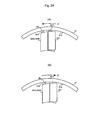
Figs. 24(A) and 24(B) are views for explaining the operating principle in the case where the check-valve function is given to thelip seal 327. - In the following, embodiments of the present invention will be described referring to the drawings.
-
Figs. 1(A) and 1(B) are an external view and a partial cross-section showing a schematic construction of therotary damper 1 of the first embodiment of the present invention. AndFig. 2 is an exploded view of therotary damper 1. - As shown in the figures, the
rotary damper 1 of the present embodiment comprises: thecase 11; the rotor (rotating body) 12 housed in thecase 11 so as to be rotatable relatively to thecase 11; the viscous fluid (such as oil, silicone or the like) 13 filling thecase 11; thelid 14 for enclosing therotor 12 together with theviscous fluid 13 in thecase 11; and a plurality of thescrews 18 for fixing thelid 14 to thecase 11. Although not shown inFigs. 1 andFig. 2 , therotary damper 1 further comprises thecheck valves 15 and the pressure-regulatingvalves 16. -
Figs. 3(A) - 3(C) are a top view, a front elevation and a bottom view of thecase 11. AndFig. 3(D) is an A-A cross-section of thecase 11 shown inFig. 3(A) . - As shown in the figures, the
case 11 comprises: thecase body 112; and theflange portion 118 formed on the outer periphery of the edge portion of thecase body 112. - In the
case body 112, the cylindrical chamber (i.e. the cylindrical shape space having the bottom) 111 is formed. Therotor 12 has therotor body 131 of the cylindrical shape and thevanes outer periphery 122 of therotor body 131. Therotor 12 is housed in thecylindrical chamber 111 such that therotor 12 can rotate on thecenter line 110 of the cylindrical chamber 111 (i.e. such that thecenter line 110 of thecylindrical chamber 111 coincides with therotation axis 120 of the rotor 12). On theinner periphery 113 of the case body 112 (i.e. thesidewall surface 113 of the cylindrical chamber 111), the pair of projectingbulkheads center line 110 of thecylindrical chamber 111. The pair ofbulkheads outer periphery 122 of the rotor body 131 (i.e. theapical surfaces 114 of the projectingbulkheads outer periphery 122 of the rotor 12), so as to partition in radial directions the ring-shaped space between theouter periphery 122 of therotor body 131 and thesidewall surface 113 of thecylindrical chamber 111. Theviscous fluid 13 fills the areas (theareas 111a - 111d inFig. 7 ) partitioned by thesebulkheads outer periphery 122 of therotor body 131 and thesidewall surface 113 of thecylindrical chamber 111. Further, in thebottom surface 116 of thecylindrical chamber 111, theopening 117 for inserting the one end portion (the lower end portion) 129a of therotor body 131 is formed. - In the
flange portion 118, the plurality of threadedholes 118a are formed. And, thescrews 18 are inserted through through-holes 143a of thelid 14 placed on theflange portion 118, and fastened into these threadedholes 118a. -
Figs. 4(A) - 4(C) are a top view, a front elevation and a bottom view of thelid 14. - As shown in the figures, in the
lid 14, theopening 141 for inserting the other end portion (theupper end portion 129b) of therotor body 131 is formed at a corresponding position of theopening 117 of thebottom surface 116. Further, in theflange portion 118 of thecase 11, the through-holes 143a for inserting thescrews 18 fastened into the threadedholes 118a are formed at corresponding positions of the threadedholes 118a. Also, a seal member such as an O-ring may be interposed between thelid 14 and thecase 11 to increase the sealing performance, so that theviscous fluid 13 will not leak out of thecylindrical chamber 111. -
Figs. 5(A) - 5(D) are a top view, a front elevation, a side elevation and a bottom view of therotor 12. - As shown in the figures, in the
rotor body 131, the through-hole 121 centering on therotation axis 120 is formed. The through-hole 121 is for inserting a shaft (not shown) which transmits rotating force from the outside to therotor 12. Thelower end portion 129a of the rotor body 131 (the through-hole 121) is slidably inserted into theopening 117 formed in thebottom surface 116 of thecylindrical chamber 111 of thecase 11. And theupper end portion 129b of the rotor body 131 (the through-hole 121) is slidably inserted into theopening 141 of thelid 14. Also, seal members such as O-rings may be interposed between theend portions rotor body 131 and the openings 117,141 to increase the sealing performance, so that theviscous fluid 13 will not leak out of thecylindrical chamber 111. - On the
outer periphery 122 of therotor body 131, the pair of vanes (rotating wings) 124a, 124b are formed along thesidewall surface 113 of thecylindrical chamber 111. The pair ofvanes sidewall surface 113 of thecylindrical chamber 111 so that the apical surfaces (i.e. the surfaces corresponding to thesidewall surface 113 of the cylindrical chamber 111) 123 of thevanes sidewall surface 113 of thecylindrical chamber 111. To eachvane Fig. 2 ) is attached. Thelip seal 127 fills gaps formed between theapical surface 123 of thevane sidewall surface 113 of thecylindrical chamber 111, gaps formed between the lower surface (the surface corresponding to thebottom surface 116 of the cylindrical chamber 111) 125 of thevane bottom surface 116 of thecylindrical chamber 111, and gaps formed between the upper surface (the surface on the side of the lid 14) 126 of thevane lid 14. -
Fig. 6(A) is a B-B cross-section of therotor 12 shown inFig. 5(B) . AndFig. 6(B) is an enlarged view of the portion C ofFig. 5(A) . - As shown in the figures, in the
vane 124a, the flow path (an orifice) 128a is formed to pass through the oneside surface 132a and theother side surface 133b of thisvane 124a. Theflow path 128a connects thearea 111a (SeeFig. 7 ) and thearea 111b (SeeFig. 7 ) of thecylindrical chamber 111. Thearea 111a is partitioned by thisvane 124a and thebulkhead 115a of thecylindrical chamber 111. Thearea 111b (SeeFig. 7 ) is partitioned by thisvane 124a and thebulkhead 115b of thecylindrical chamber 111. Similarly, in thevane 124b, theflow path 128b is formed to pass through oneside surface 132b and theother side surface 133b of thisvane 124b. The pass through connects thearea 111c (SeeFig. 7 ) and thearea 111d (SeeFig. 7 ) of thecylindrical chamber 111. Thearea 111c is partitioned by thevane 124b and thebulkhead 115a of thecylindrical chamber 111. Thearea 111d is partitioned by thevane 124b and thebulkhead 115b of thecylindrical chamber 111. - Each of the
flow paths check valve 15 and the pressure-regulatingvalve 16 as a pair. - Inside each
flow path flow path openings side surface vane other side surface vane flow path openings flow path section 1280, the secondflow path section 1281 whose flow path cross-section size in the radial direction is larger than that of the firstflow path section 1280. And the thirdflow path section 1282 whose flow path cross-section size in the radial direction is smaller than that of the secondflow path section 1281. - The second
flow path section 1281 houses thecheck valve 15 slidably in the flow direction of theviscous fluid 13. And the thirdflow path section 1282 houses the pressure-regulatingvalve 16. The secondflow path section 1281 is formed so as to adjoin the side of thearea Fig. 7 ) to the thirdflow path section 1282, wherein the filledviscous fluid 13 in thearea rotor 12 is rotated in the normal rotation direction (the direction α in the present embodiment). - The
check valve 15 is a plate-like member placed inside the secondflow path section 1281 so as to open and close the secondflow path section 1281, and slides within the secondflow path section 1281 in directions that depend on the rotation direction of therotor 12. Further, in thecheck valve 15, the through-hole 151 through which the viscous fluid 13 passes is formed. This through-hole 151 is opened and closed by the pressure-regulatingvalve 16. - The pressure-regulating
valve 16 comprises: theneedle 160 for regulating the flow rate of theviscous fluid 13 passing through the through-hole 151 of thecheck valve 15; and theelastic body 162 such as a spring, which biases theneedle 160 toward the secondflow path section 1281. Theneedle 160 comprises: the taperedplug portion 161 for blocking the through-hole 151 of thecheck valve 15; and the rod-like stopper 163 provided at the end portion of theplug portion 161 on the side of thecheck valve 15. Theneedle 160 is inserted in the through-hole 151 of thecheck valve 15 from the side of the thirdflow path section 1282 so that thestopper 163 protrudes toward the secondflow path section 1281. When thecheck valve 15 moves toward the thirdflow path section 1282, theplug portion 161 is inserted in the through-hole 151 of thecheck valve 15. As a result, the through-hole 151 of thecheck valve 15 is blocked by theplug portion 161. Further, when theneedle 160 moves toward the first and secondflow path sections elastic body 162, thestopper 163 abuts against theinner wall 1283 of theflow path hole 151 of thecheck valve 15. As a result, the movement of theplug portion 161 toward the first and secondflow path sections - For example, as shown in
Fig. 6(C) , theflow path hole 1288 in thevane flow path sections 1280 and 1281) of theflow path check valve 15 and the pressure-regulatingvalve 16 in this order into the through-hole 1288; and then fitting theblock 1289 in the through-hole 1288, wherein a part (i.e. the other flow path opening 1285 and the third flow path section 1282) of theflow path block 1289. - Here, to realize smooth movement of the
needle 160, it is possible to provide guides (for example, three or more protrusions formed on the end surface portion of the through-hole 151 on the side of the first flow path section 1280) for preventing play of thestopper 163 in the radial direction of the through-hole 151 of thecheck valve 15. - Next, the operating principle of the
rotary damper 1 will be described.Figs. 7(A) and 7(B) andFig. 8 are views for explaining the operating principle of therotary damper 1. - As shown in
Figs. 7(A) and 7(B) , when therotor 12 rotates in the normal rotation direction (the direction α in the present embodiment) relatively to thecase 11, thecheck valve 15 slides in thesecond flow path 1281 up to theboundary 1286 between the secondflow path section 1281 and the thirdflow path section 1282. - Here, as shown in
Fig. 7(A) , when rotating force (rotating speed in the direction α) applied to therotor 12 or thecase 11 is less than a predetermined value determined by the elastic coefficient of theelastic body 162 of the pressure-regulatingvalve 16, theplug portion 161 of theneedle 160 pressed by theelastic body 162 remains pushed in the through-hole 151 of thecheck valve 15. And thereby theflow path cylindrical chamber 111, the movement of theviscous fluid 13 between theareas 111a - 111d partitioned by thebulkheads vanes rotor 12 is limited to movement through gaps etc. between theapical surfaces 114 of thebulkheads outer periphery 122 of therotor 12. Accordingly, the pressures of theviscous fluid 13 in theareas - As shown in
Fig. 7(B) , when the rotating force applied to therotor 12 or thecase 11 is above the above-mentioned predetermined value, theneedle 160 is pushed back toward the thirdflow path section 1282 by the pressure of theviscous fluid 13 going to flow through theflow path plug portion 161 of theneedle 160 leaves the through-hole 151 of thecheck valve 15. And thereby theflow path cylindrical chamber 111, the restriction of the movement betweenareas 111a - 111d partitioned by thebulkheads vanes rotor 12 is cancelled. And theviscous fluid 13 moves from theareas areas flow paths viscous fluid 13 in theareas - On the other hand, as shown in
Fig. 8 , when therotor 12 rotates in the reverse rotation direction (the direction β in the present embodiment) relatively to thecase 11, thecheck valve 15 slides in thesecond flow path 1281 up to theboundary 1287 between the firstflow path section 1280 and the secondflow path section 1281. - Here, since the movement of the
needle 160 toward the secondflow path section 1281 is limited by thestopper 163, theplug portion 161 of theneedle 160 is not pushed in the through-hole 151 of thecheck valve 15. And thereby theflow path viscous fluid 13 moves from thearea area flow path viscous fluid 13 in theareas - Hereinabove, the first embodiment of the present invention has been described.
- In the present embodiment, the
rotary damper 1 generates strong damping torque against the rotating force of the normal rotation direction applied to therotor 12 or thecase 11, by limiting the movement of theviscous fluid 13 filling the inside of thecylindrical chamber 111 through theflow paths rotary damper 1 is provided with the pressure-regulatingvalves 16 which cancel the limitation of the movement of theviscous fluid 13 from the high-pressure side to the low-pressure side when the rotating force exceeds the predetermined value. Thus, according to the present embodiment, even if the rotating force exceeding the assumed value is applied to therotor 12 or thecase 11, the pressure of theviscous fluid 13 filling the inside of thecylindrical chamber 111 can be kept below the predetermined value, reducing the possibility that therotary damper 1 is damaged. - Further, in the present embodiment, the
vane 124a of therotor 12 is provided with theflow path 128a which connects theareas bulkheads cylindrical chamber 111 and thisvane 124a. Further, thevane 124b of therotor 12 is provided with theflow path 128b which connects theareas bulkheads cylindrical chamber 111 and thisvane 124b. Since thecheck valve 15 and the pressure-regulatingvalve 16 have the above-described construction, each of theflow paths check valve 15 and the pressure-regulatingvalve 16 as a pair in its inside. Thus, according to the present embodiment, thecheck valve 15 and the pressure-regulatingvalve 16 are placed in thecommon flow path rotary damper 1. - In the present embodiment, the
flow path vane rotor 12. And thecheck valve 15 and the pressure-regulatingvalve 16 are provided as a pair in each of theflow paths flow paths bulkheads cylindrical chamber 111 of thecase 11. And it is possible to provide thecheck valve 15 and the pressure-regulatingvalve 16 as a pair in theflow path -
Figs. 9(A) and 9(B) are an external view and a partial cross-section showing a schematic construction of therotary damper 2 according to the second embodiment of the present invention. AndFig. 10 is an exploded view of therotary damper 2. - As shown in the figures, the
rotary damper 2 of the present embodiment comprises: thecase 21; the rotor (the rotating body) 12a housed in thecase 21 so as to be rotatable relatively to thecase 21; theviscous fluid 13 filling thecase 21; thelid 14 for enclosing therotor 12a together with theviscous fluid 13 in thecase 21; the pair ofbackflow prevention mechanisms screws 18 for fixing thelid 14 to thecase 21. - Here, the
viscous fluid 13, thescrews 18 and thelid 14 are similar to those used in therotary damper 1 of the first embodiment. Further, the construction of therotor 12a is similar to that of therotor 12 used in therotary damper 1 of the first embodiment except that theflow paths vanes -
Figs. 11(A) - 11(C) are a top view, a front elevation and a bottom view of thecase 21. AndFig. 11(D) is a D-D cross-section of thecase 21 shown inFig. 11(A) . - As shown in the figures, the
case 21 comprises: thecase body 212; and theflange portion 218 formed on the outer periphery of the edge portion of thecase body 212. - In the
case body 212, the cylindrical chamber (i.e. the cylindrical shape space having the bottom) 211 is formed. Therotor 12a has therotor body 131 of the cylindrical shape, and thevanes outer periphery 122 of therotor body 131. Therotor 12a is housed in thecylindrical chamber 211 such that therotor 12a can rotate on thecenter line 210 of the cylindrical chamber 211 (i.e. such that thecenter line 210 of thecylindrical chamber 211 coincides with the rotation axis 220 of therotor 12a). In thebottom surface 216 of thecylindrical chamber 211, theopening 217 for inserting the one end portion (the lower end portion) 129a of therotor 12a is formed. - On the
inner periphery 213 of the case body 212 (i.e. thesidewall surface 213 of the cylindrical chamber 211), the pair of projectingbulkheads center line 210 of thecylindrical chamber 211. The projectingbulkheads outer periphery 122 of the rotor body 131 (i.e. theapical surfaces 114 of the projectingbulkheads outer periphery 122 of the rotor 12), so as to partition in radial directions the ring-shaped space between theouter periphery 122 of therotor body 131 and thesidewall surface 213 of thecylindrical chamber 211. Theviscous fluid 13 fills the areas (theareas 211a - 211d inFig. 13 ) partitioned by thesebulkheads outer periphery 122 of therotor body 131 and thesidewall surface 213 of thecylindrical chamber 211. - In the
bulkhead 215a, the groove-like flow path 228a is formed. The groove-like flow path 228a connects thearea 211a (SeeFig. 13 ) in thecylindrical chamber 211 and thearea 211c (SeeFig. 13 ) in thecylindrical chamber 211. Here, thearea 211a is formed by thebulkhead 215a and thevane 124a of therotor 12a. And thearea 211c is formed by thebulkhead 215a and thevane 124b of therotor 12a. Thisflow path 228a houses slidably thebackflow prevention mechanism 22a with pressure-regulating function. Similarly, in thebulkhead 215b, theflow path 228b is formed. Theflow path 228b connects thearea 211d (SeeFig. 13 ) in thecylindrical chamber 211 and thearea 211b (SeeFig. 13 ) in thecylindrical chamber 211. Here, thearea 211d is formed by thebulkhead 215b and thevane 124b of therotor 12a. And thearea 211b is formed by thebulkhead 215b and thevane 124a of therotor 12a. Thisflow path 228b houses slidably thebackflow prevention mechanism 22b with pressure-regulating function. - Further, in each of the
flow paths 228a, the 228b, the projectingportion 219 is formed. The projectingportion 219 narrows the width of a part of the flow path in the radial direction to limit the sliding range of thebackflow prevention mechanism - In the
flange portion 218, the plurality of threadedholes 218a are formed. And thescrews 18 are inserted through through-holes 143a of thelid 14 placed on theflange portion 118, and fastened into these threadedholes 218a. -
Figs. 12(A) - 12(C) are a top view, a front elevation and a bottom view of thebackflow prevention mechanism Fig. 12(D) is an E-E cross-section of thebackflow prevention mechanism Fig. 12(C) . - As shown in the figures, the
backflow prevention mechanism check valve 25 and the pressure-regulatingvalve 26. - The
check valve 25 comprises: the plate-like valve portion 251 which slides in the circumferential direction to open and close the one flow path opening (i.e. the flow path opening 229a, 229b (SeeFig. 13 ) on the side of thearea viscous fluid 13 is pressurized, when therotor 12a is rotated in the normal rotation direction (the direction α (SeeFig. 13 ) in the present embodiment)); thestoppers 252 which limit the sliding range of thevalve portion 251 in cooperation with the projectingportion 219 in theflow path portion 254 which holds the pressure-regulatingvalve 26; and the connectingportion 255 which connects thevalve portion 251, thestoppers 252 and the holdingportion 254. - Here, in the
valve portion 251, the through-hole 253 which is opened and closed by the pressure-regulatingvalve 26 is formed. Further, the holdingportion 254 and thestoppers 252 are formed so as to be located on the side of thearea Fig. 13 ) in which the pressure of the filledviscous fluid 13 is reduced when therotor 12a is rotated in the normal rotation direction (the direction α (SeeFig. 13 ) in the present invention). Further, the connectingportion 255 has such a length that thevalve portion 251 is at a given distance away from the flow path opening 229a, 229b of theflow path rotor 12a rotates in the reverse rotation direction (the direction β (SeeFig. 14 ) in the present embodiment) and thestoppers 252 abut against the projectingportions 219 in thebulkhead - The pressure-regulating
valve 26 comprises: theneedle 264 for regulating the flow rate of theviscous fluid 13 passing through the through-hole 253 of thevalve portion 251 of thecheck valve 25; and theelastic body 262 such as a spring, which is fixed at one end to the holdingportion 254 of thecheck valve 25 and biases at the other end theneedle 264 toward thearea needle 264 comprises: the taperedplug portion 261 for blocking the through-hole 253 of thevalve portion 251 of thecheck valve 25; and the rod-like guide 263 provided at the end portion of theplug portion 261 on the side of thevalve portion 251. Theguide 263 is inserted in the through-hole 253 of thevalve portion 251 from the side of thearea plug portion 261 into the through-hole 253 of thevalve portion 251 of thecheck valve 25. When theneedle 264 moves toward thevalve portion 251 of thecheck valve 25 due to biasing by theelastic body 262, then theplug portion 261 is inserted into the through-hole 253 of the valve portion, being guided by theguide 263. As a result, the through-hole 253 of thevalve portion 251 of thecheck valve 25 is blocked by theplug portion 261. - Here, to realize smooth movement of the
needle 264, it is possible to provide guides (for example, three or more protrusions formed on the outer end surface portion of the through-hole 253) for preventing play of theguide 263 in the radial direction of the through-hole 253 of thevalve portion 251 - Next, the operating principle of the
rotary damper 2 will be described.Figs. 13(A) and 13(B) andFig. 14 are view for explaining the operating principle of therotary damper 2. - As shown in
Figs. 13(A) and 13(B) , when therotor 12a rotates in the normal rotation direction (the direction α in the present embodiment) relatively to thecase 21, thebackflow prevention mechanism flow path valve portion 251 of thecheck valve 25 blocks the flow path opening 229a, 229b of theflow path - Here, as shown in
Fig. 13(A) , when the rotating force (the rotating speed in the direction α) applied to therotor 12a or thecase 21 is less than the predetermined value determined by the elastic coefficient of theelastic body 262 of the pressure-regulatingvalve 26, theplug portion 261 of theneedle 264 pressed by theelastic body 262 remains pushed in the through-hole 253 of thevalve portion 251. And thereby theflow path cylindrical chamber 211, the movement of theviscous fluid 13 between theareas 211a - 211d partitioned by thebulkheads vanes rotor 12a is limited to movement through gaps etc. formed between theapical surfaces 214 of thebulkheads outer periphery 122 of therotor body 131. Accordingly, the pressures of theviscous fluid 13 in theareas - As shown in
Fig. 13(B) , when the rotating force applied to therotor 12a or thecase 21 is above the above-mentioned predetermined value, theneedle 264 is pushed back owing to the pressure by theviscous fluid 13 going to flow through theflow path plug portion 261 of theneedle 264 leaves the through-hole 253 of thevalve portion 251, to open theflow path cylindrical chamber 211, the restriction on the movement of theviscous fluid 13 between theareas 211a - 211d partitioned by thebulkheads vanes rotor 12a is canceled, and theviscous fluid 13 moves from theareas areas flow paths holes 253 of theplug portions 251. Thus, it is possible to prevent the pressures of theviscous fluid 13 in theareas - On the other hand, as shown in
Fig. 14 , when therotor 12a rotates in the reverse rotation direction (the direction β in the present embodiment) relatively to thecase 21, thebackflow prevention mechanism flow path stopper 252 of thecheck valve 25 abuts against the projectingportions 219 in theflow path valve portion 251 moves up to a position away from the flow path opening 229a, 229b of theflow path flow path viscous fluid 13 moves from thearea area flow path areas - Hereinabove, the second embodiment of the present invention has been described.
- Also in the present embodiment, similarly to the above-described first embodiment, when the rotating force exceeding the assumed value is applied to the
rotor 12a or thecase 21, the pressure on theviscous fluid 13 filling the inside of thecylindrical chamber 211 can be kept below a predetermined value, reducing the possibility that therotary damper 2 is damaged. Further, since the pressure-regulatingvalve 26 is incorporated in thecheck valve 25 to obtain thebackflow prevention mechanism check valve 25 and the pressure-regulatingvalve 26 can be placed in thecommon flow path rotary damper 2. - In the present embodiment, the
flow paths bulkheads cylindrical chamber 211, and thebackflow prevention mechanisms flow paths flow paths vanes rotor 12a, and to provide thebackflow prevention mechanisms flow paths -
Figs. 15(A) and 15(B) are external view and a partial cross-section showing a schematic construction of therotary damper 3 according to the third embodiment of the present invention. AndFig. 16 is an exploded view of therotary damper 3. - As shown in the figures, the
rotary damper 3 of the present embodiment comprises: thecase 31; the rotor (the rotating body) 32 housed in thecase 31 so as to be rotatable relatively to thecase 31; theviscous fluid 13 filling thecase 31; thelid 14 for enclosing therotor 32 together with theviscous fluid 13 in thecase 31; and the plurality ofscrews 18 for fixing thelid 14 to thecase 11. Although not shown inFig. 15 , therotary damper 3 further comprises thecheck valves 35 and the pressure-regulatingvalves 36. - Here, the
viscous fluid 13, thescrews 18 and thelid 14 are similar to those used in therotary damper 1 of the first embodiment, and thus description of these will be omitted in the following. -
Figs. 17(A) - 17(C) are a top view, a front elevation and a bottom view of thecase 31. AndFig. 17(D) is an F-F cross-section of thecase 31 shown inFig. 17(A) . - As shown in the figures, the
case 31 comprises: thecase body 312; and theflange portion 318 formed on the outer periphery of the edge portion of thecase body 312. - In the
case body 312, the cylindrical chamber (i.e. the space of the cylindrical shape having the bottom) 311 is formed. Therotor 32 has therotor body 331 of the cylindrical shape and thevanes outer periphery 322 of therotor body 331. Therotor 32 is housed in thecylindrical chamber 311 such that therotor 32 can rotate on thecenter line 310 of the cylindrical chamber 311 (i.e. such that thecenter line 310 of thecylindrical chamber 311 coincides with therotation axis 320 of the rotor 32). On theinner periphery 313 of the case body 312 (i.e. thesidewall surface 313 of the cylindrical chamber 311), the pair of projectingbulkheads center line 310 of thecylindrical chamber 311. The projectingbulkheads outer periphery 322 of the rotor body 331 (i.e. theapical surfaces 314 of the projectingbulkheads side surface 322 of the rotor 32), so as to partition in radial directions the ring-shaped space between theouter periphery 322 of therotor body 331 and thesidewall surface 313 of thecylindrical chamber 311. Theviscous fluid 13 fills the areas (theareas 311a - 311d inFig. 22 ) partitioned by thesebulkheads outer periphery 322 of therotor body 331 and thesidewall surface 313 of thecylindrical chamber 311. In thebottom surface 316 of thecylindrical chamber 311, theopening 317 for inserting one end portion (the lower end portion) 329a of therotor body 331 is formed. - Further, in the
bulkhead 315a, the flow path (the orifice) 338a for check valve is formed. Theflow path 338a connects thearea 311a (SeeFig. 22 ) and thearea 311c (SeeFig. 22 ). Thearea 311a is formed by thisbulkhead 315a and thevane 324a of therotor 32 in thecylindrical chamber 311. And thearea 311c (SeeFig. 22 ) is formed by thisbulkhead 315a and thevane 324b of therotor 32 in thecylindrical chamber 311. Similarly, in theother bulkhead 315b, the flow path (the orifice) 338b for check valve is formed. Theflow path 338b connects thearea 311b (SeeFig. 22 ) and thearea 311d (SeeFig. 22 ). Thearea 311b is formed by thisbulkhead 315b and thevane 324a of therotor 32 in thecylindrical chamber 311. And thearea 311d (SeeFig. 22 ) is formed by thisbulkhead 315b and thevane 324b of therotor 32 in thecylindrical chamber 311. -
Fig. 18(A) is a G-G cross-section of thecase 31 shown inFig. 17(B) . AndFig. 18(B) is an enlarged view of the portion H ofFig. 18(A) . - As shown in the figures, the
spherical check valve 35 is provided in the inside of each of theflow paths - In each of the
flow paths flow path section 3381 for check valve and the secondflow path section 3382 for check valve are formed. The secondflow path section 3382 for check valve has a flow path cross-section size in the radial direction larger than that of the firstflow path section 3381 for check valve. The secondflow path section 3382 for check valve has a diameter larger than that of thecheck valve 35. The secondflow path section 3382 houses thecheck valve 35 slidably so that thecheck valve 35 opens and closes the firstflow path section 3381 for check valve. Further, in the secondflow path section 3382 for check valve, thestopper 3383 for limiting the sliding range of thecheck valve 35 is formed. The firstflow path section 3381 for check valve is formed so as to be adjacent to the side of thearea viscous fluid 13 is reduced when therotor 32 is rotated in the normal rotation direction (the direction α in the present embodiment, SeeFig. 22 ). -
Figs. 19(A) - 19(D) are a top view, a front elevation, a side elevation and a bottom view of therotor 32. - As shown in the figures, in the
rotor body 331, the through-hole 321 centering on therotation axis 320 is formed. The through-hole 321 inserts a shaft (not shown) that transmits the rotating force from the outside to therotor 32. Thelower end portion 329a of the rotor body 331 (the through-hole 321) is slidably inserted into theopening 317 formed in thebottom surface 316 of thecylindrical chamber 311 of thecase 31. And theupper end portion 329b of the rotor body 331 (the through-hole 321) is slidably inserted into theopening 141 of thelid 14. Also, seal members such as O-rings may be interposed between theend portions rotor body 331 and theopenings viscous fluid 13 will not leak out of thecylindrical chamber 311. - Further, on the
outer periphery 322 of therotor body 331, the pair of vanes (rotating wings) 324a, 324b are formed along therotation axis 320 of therotor 32. Thevanes sidewall surface 313 of thecylindrical chamber 311 such that apical surfaces (i.e. the surfaces corresponding to theside wall surface 313 of the cylindrical chamber 311) 323 of thevanes sidewall surface 313 of thecylindrical chamber 311. The lip seal 327 (SeeFig. 15 ) is attached to each of thevanes lip seal 327 fills gaps formed between theapical surface 323 of thevane sidewall surface 313 of thecylindrical chamber 311, and gaps formed between the lower surface (the surface corresponding to thebottom surface 316 of the cylindrical chamber 311) 325 of thevane bottom surface 316 of thecylindrical chamber 311. And also thelip seal 327 fills gaps formed between the upper surface (the surface on the side of the lid 14) 326 of thevane lower surface 142 of thelid 14. -
Fig. 20(A) is an I-I cross-section of therotor 32 shown inFig. 19(B) .Fig. 20(B) is an enlarged view of the portion J ofFig. 20(A) . AndFig. 20(C) is a view for explaining a method of preparing theflow paths - In one
vane 324a, the flow path (the orifice) 328a for pressure-regulating valve is formed. Theflow path 328a for pressure-regulating valve connects thearea 311a (SeeFig. 22 ) in thecylindrical chamber 311 and thearea 311b (SeeFig. 22 ) in thecylindrical chamber 311. Thearea 311a is formed by thevane 324a and thebulkhead 315a of thecylindrical chamber 311. And thearea 311b is formed by thevane 324a and thebulkhead 315b of thecylindrical chamber 311. Similarly, in theother vane 324b, the flow path (the orifice) 328b for pressure-regulating valve is formed. Theflow path 328b for pressure-regulating valve connects thearea 311c (SeeFig. 22 ) in thecylindrical chamber 311 and thearea 311d (SeeFig. 22 ) in thecylindrical chamber 311. Thearea 311c is formed by thevane 324b and thebulkhead 315a of thecylindrical chamber 311. And thearea 311d is formed by thevane 324b and thebulkhead 315b of thecylindrical chamber 311. - In each of the
flow paths flow path section 3282 for pressure-regulating valve is formed between the flow path opening 3280 formed in the oneside surface vane other side surface vane flow path section 3282 for pressure-regulating valve has a flow path cross-section size in the radial direction larger than those of theflow path openings flow path section 3282 for pressure-regulating valve is shifted from the axes of theflow path openings flow path section 3282 for pressure-regulating valve houses the pressure-regulatingvalve 36. - The pressure-regulating
valve 36 comprises: theneedle 360 for regulating the flow rate of theviscous fluid 13 passing through the flow path opening 3280 of theflow path elastic body 362 such as a spring, which presses theneedle 360 toward the flow path opening 3280 of theflow path flow path area Fig. 22 ). The filledviscous fluid 13 in thearea rotor 32 is rotated in the normal rotation direction (the direction α in the present embodiment). - The
needle 360 comprises: the taperedplug portion 361 for blocking the flow path opening 3280 of theflow path guide 363 provided at the tip of theplug portion 361. Theguide 363 is inserted in the flow path opening 3280 of theflow path area plug portion 361 into the flow path opening 3280 of theflow path needle 360 moves toward the flow path opening 3280 of theflow path elastic body 362, theplug portion 361 is guided by theguide 363, and is inserted into the flow path opening 3280 of theflow path flow path plug portion 361. - For example, as shown in
Fig. 20(C) , theflow path hole 3284 as a part (i.e. the flow path opening 3280 and theflow path section 3282 for pressure-regulating valve) of theflow path vane valve 36 into the through-hole 3284; and then fitting in theblock 3285 in which a part (i.e. the other flow path opening 3281) of theflow path - Here, to realize smooth movement of the
needle 360, it is possible to provides guides (for example, three or more protrusions formed on the end surface portion of the flow path opening 3280 on the side of theflow path section 3282 for pressure-regulating valve) for preventing play of theguide 363 in the radial direction of theflow path opening 3280. - Next, the operating principle of the
rotary damper 3 will be described.Figs. 21 - 23 are views for explaining the operating principle of therotary damper 3. - As shown in
Figs. 21 and22 , when therotor 32 rotates in the normal rotation direction (the direction α in the present embodiment) relatively to thecase 31, thecheck valve 35 slides in the secondflow path section 3382 for check valve up to the boundary between the firstflow path section 3381 for check valve and the secondflow path section 3382 for check valve. And thereby thecheck valve 35 blocks the firstflow path section 3381 for check valve. As a result, theflow path - Here, as shown in
Fig. 21 , when the rotating force (the rotating speed in the direction α) applied to therotor 32 or thecase 31 is less than a predetermined value determined by the elastic coefficient of theelastic body 362 of the pressure-regulatingvalve 36, theplug portion 361 of theneedle 360 pressed by theelastic body 362 remains pushed in the flow path opening 3280 of theflow path flow path cylindrical chamber 311, the movement of theviscous fluid 13 between theareas 311a - 311d partitioned by thebulkheads vanes rotor 32 is limited to movement through gaps etc. formed between theapical surfaces 314 of thebulkheads outer periphery 322 of therotor body 331. Accordingly, the pressures of theviscous fluid 13 in theareas - As shown in
Fig. 22 , when the rotating force applied to therotor 32 or thecase 31 is above the above-mentioned predetermined value, theneedle 360 is pushed back due to the pressure by theviscous fluid 13 going to flow through theflow path plug portion 361 of theneedle 360 leaves the firstflow path section 3281 for pressure-regulating valve. And thereby theflow path viscous fluid 13 through theflow paths viscous fluid 13 moves from theareas areas flow paths viscous fluid 13 in theareas - On the other hand, as shown in
Fig. 23 , when therotor 32 rotates in the reverse rotation direction (the direction β in the present embodiment) relatively to thecase 31, thecheck valve 35 slides toward the side of thearea flow path section 3382 for check valve until thecheck valve 35 abuts against thestopper 3383. As a result, thecheck valve 35 leaves the firstflow path section 3381 for check valve. And thereby theflow path viscous fluid 13 moves from thearea area flow path viscous fluid 13 in theareas - Hereinabove, the third embodiment of the present invention has been described.
- Also in the present embodiment, similarly to the above-described first and second embodiments, when the rotating force exceeding the assumed value is applied to the
rotor 32, the pressure of theviscous fluid 13 filling the inside of thecylindrical chamber 311 can be kept below a predetermined value, reducing the possibility that the rotary damper is damaged. Further, theflow path valve 36 in the inside is formed in thevane rotor 32, and theflow path check valve 35 in the inside is formed in thebulkhead cylindrical chamber 311. Thus, it is possible to reduce the size of therotary damper 3 in comparison with the case where these flow paths are formed together in either thevanes bulkheads - In the present embodiment, the
flow paths check valves 35 are formed in thebulkheads cylindrical chamber 311, and theflow paths valve 36 are formed in thevanes rotor 32. However, the present invention is not limited to this. For example, it is possible that the flow paths for the pressure-regulatingvalves 36 are formed in thebulkheads cylindrical chamber 311, and the flow paths for thecheck valves 35 are formed in thevanes rotor 32. Or, in the case where requirement for downsizing of therotary damper 3 is not rigid, these flow paths may be formed together in either thevanes bulkheads - Further, in the present embodiment, it is possible to give a function as the check valve to the
lip seal 327 attached to thevane rotor 32, to omit thecheck valve 35 and theflow path apical portion 3271 of thelip seal 327. As shown inFig. 24(A) , theapical portion 3271 is deformed in the direction of blocking thegap 38 between theapical surface 323 of thevane sidewall surface 313 of thecylindrical chamber 311 due to the pressure of theviscous fluid 13 flowing through thegap 38, when therotor 32 rotates in the normal rotation direction (the direction α in the present embodiment) relatively to thecase 31. And as shown inFig. 24(B) , theapical portion 3271 is deformed in the direction of releasing thegap 38 due to the pressure of theviscous fluid 13 flowing through thegap 38, when therotor 32 rotates in the reverse rotation direction (the direction β in the present embodiment) relatively to thecase 31. Thus, it is possible to omit thecheck valves 35 and theflow paths rotary damper 3 can be produced at low cost. - The rotary dampers 1 - 3 of the above-described embodiments have been described about examples where the pair of
bulkheads cylindrical chamber vanes rotor - The rotary dampers 1 - 3 of the above-described embodiments can be widely applied to a seat with a reclining mechanism used, for example, in a car, a railroad vehicle, an airplane, a ship, or the like.
- The present invention can be applied to fields where pressure of viscous fluid filling a cylindrical chamber of a rotary damper should be kept less than or equal to a predetermined value as in the case of a seat with reclining mechanism used in a car, a railroad vehicle, an airplane, a ship, or the like.
- 1-3 : rotary damper, 11 : case, 12, 12a : rotor (rotating body), 13 : viscous fluid, 14 : lid, 15 : check valve, 16 : pressure-regulating valve, 17 : lip seal, 18 : screw, 21 : case, 22a, 22b : backflow prevention mechanism with pressure-regulating function, 25 : check valve, 26 : pressure-regulating valve, 31 : case, 32 : rotor (rotating body), 35 : check valve, 110 : center line 110 of cylindrical chamber 111, 111 : cylindrical chamber, 112 : case body, 113 : inner periphery of case body 112 (sidewall surface of cylindrical chamber 111), 114 : apical surface of bulkhead 115a, 115b, 115a, 115b : bulkhead, 116 : bottom surface of cylindrical chamber 111, 117 : opening of cylindrical chamber 111, 118 : flange portion, 118a : threaded holes of flange portion 118, 120 : rotation axis of rotor 12, 121 : through-hole of rotor body 131, 122 : outer periphery of the rotor body 131, 123 : apical surfaces of vane 124a, 124b, 124a, 124b : vane, 125 : lower surface of vane 124a, 124b, 126 : upper surface of vane 124a, 124b, 127 : lip seal, 128a, 128b : flow path (orifice), 129a : lower end portion of rotor body 131, 129b : upper end portion of rotor body 131, 131 : rotor body, 132a, 132b : side surface of vane 124a, 124b, 133a, 133b : side surface of vane 124a, 124b, 141 : opening of lid 14, 142 : lower surface of lid 14, 143a : through-hole of lid 14, 151 : through-hole of check valve 15, 160 : needle of the pressure-regulating valve 16, 161 : plug portion of needle 160, 162 : elastic body of pressure-regulating valve 16, 163 : stopper of needle 160, 210: center line of cylindrical chamber 211, 211 : cylindrical chamber, 212 : case body, 213 : inner periphery of case body 212 (sidewall surface of cylindrical chamber 211), 214 : apical surface of bulkhead 215a, 215b, 215a, 215b : bulkhead, 216 : bottom surface of cylindrical chamber 211, 217 : opening of cylindrical chamber 211, 218 : flange portion, 218a : threaded holes of flange portion 218, 219 : projecting portion in flow path 228a, 228b, 228a, 228b : flow path, 229a, 229b : opening of flow path 228a, 228b, 251 : valve portion of check valve 25, 252 : stopper of check valve 25, 253 : through-hole of valve portion 251, 254 : holding portion of check valve 25, 255 : connecting portion of valve portion 251, 261 : plug portion of pressure-regulating valve 26, 262 : elastic body of pressure-regulating valve 26, 263 : guide of needle 264, 264 : needle of pressure-regulating valve 26, 310 : center line of cylindrical chamber 311, 311 : cylindrical chamber, 313 : sidewall surface of cylindrical chamber 311, 314 : apical surface of bulkhead 315a, 315b, 315a, 315b : bulkhead, 316 : bottom surface of cylindrical chamber 311, 317 : opening of cylindrical chamber 311, 320 : rotation axis of rotor 32, 321 : through-hole of rotor body 331, 322 : outer periphery of rotor body 331, 323 : apical surface of the vane 324a, 324b, 324a, 324b : vane, 325 : lower surface of vane 324a, 324b, 326 : upper surface of vane 324a, 324b, 327 : lip seal, 328a, 328b : flow path for pressure-regulating valve, 329a : lower end portion of rotor body 331, 329b : upper end portion of rotor body 331, 331 : rotor body, 332a, 332b : side surface of vane 324a, 324b, 333a, 333b : side surface of vane 324a, 324b, 338a, 338b : flow path for check valve, 360 : needle, 1280 : first flow path section, 1281 : second flow path section, 1282 : third flow path section, 1283 : inner wall of flow path 128a, 128b, 1284, 1285 : flow path opening of flow path 128a, 128b, 1286 : boundary between second flow path section 1281 and third flow path section 1282, 1287 : boundary between the first flow path section 1280 and the second flow path section 1281, 1288 : through-hole in vane 124a, 124b, 1289 : block, 3271 : apical portion of lip seal 327, 3280, 3281 : flow path opening of flow path for pressure-regulating valve 328a, 328b, 3282 : flow path section for pressure-regulating valve, 3284 : through-hole of vane 324a, 324b, 3285 : block, 3381 : first flow path section for the check valve, 3382 : second flow path section for the check valve, 3383 : stopper of check valve 35
Claims (9)
- A rotary damper for generating damping torque against applied rotating force by restricting movement of filled viscous fluid, comprising:a pressure-regulating valve which opens for canceling the restriction of movement of the viscous fluid, when the rotating force is above a predetermined value.
- A rotary damper of Claim 1, further comprising:a case having a cylindrical chamber filled with the viscous fluid;a rotor housed in the cylindrical chamber so as to be rotatable on a center line of the cylindrical chamber relatively to the case; anda check valve which opens and closes depending on a direction of rotation of the rotor; wherein:on a sidewall surface of the cylindrical chamber, there is formed a projecting bulkhead along the center line such that an apical surface of the bulkhead is close to an outer periphery of the rotor;on the outer periphery of the rotor, there is formed a vane whose apical surface is close to a side surface of the cylindrical chamber;the check valve closes for relative rotation of the rotor to the case in a normal rotation direction, to restrict movement of the viscous fluid between areas partitioned by the bulkhead and the vane, while the check valve opens for relative rotation of the rotor to the case in a reverse rotation direction, to allow movement of the viscous fluid between the areas partitioned by the bulkhead and the vane; andthe pressure-regulating valve opens to cancel the restriction of movement of the viscous fluid between the areas partitioned by the bulkhead and the vane, when the rotating force, which is applied for rotating the rotor in the normal rotation direction in relatively to the case, is above the predetermined value.
- A rotary damper of Claim 2, wherein:in at least one of the bulkhead and the vane, there is formed a flow path which connects the areas partitioned by the bulkhead and the vane; andthe pressure-regulating valve opens the flow path when the rotating force applied for rotating the rotor relatively in the normal rotation direction is above the predetermined value, and closes the flow path when the rotating force is less than the predetermined value.
- A rotary damper of Claim 3, wherein:the check valve closes the flow path when the rotor is rotated in the normal rotation direction relatively to the case, and opens the flow path when the rotor is rotated in the reverse rotation direction relatively to the case; andthe pressure-regulating valve opens the flow path closed by the check valve, when the rotating force applied for rotating the rotor in the normal rotation direction relatively to the case is above the predetermined value.
- A rotary damper of Claim 4, wherein:in the flow path, there are formed a first flow path section for housing the check valve slidably and a second flow path section for housing the pressure-regulating valve;As opposed to the second flow path section, the first flow path section is adjacent to an area in which pressure of the viscous fluid is increased when the rotor is rotated in the normal rotation direction relatively to the case, between the areas partitioned by the bulkhead and the vane;the check valve is a plate-like member in which a through-hole is formed;the pressure-regulating valve comprises: a plug portion for the through-hole of the check valve; an elastic body pressing the plug portion toward the first flow path section; and a stopper for limiting movement of the plug portion into the first flow path section;when the rotor is rotated in the normal rotation direction relatively to the case, the check valve slides up to an end portion of the first flow path section on a side of the second flow path section, wherein if the rotating force is less than the predetermined value, the plug portion pressed by the elastic body is pushed into the through-hole of the check valve, to close the flow path, and if the rotating force is above the predetermined value, the plug portion is pushed back by pressure of the viscous fluid going to flow the flow path, and leaves the through-hole of the check valve, to open the flow path; andwhen the rotor is rotated in the reverse rotation direction relatively to the case, the check valve slides in a direction that the check valve leaves the end portion of the first flow path section on the side of the second flow path section, and the plug portion whose movement into the first flow path section is limited by the stopper is not pushed into the through-hole of the check valve, to open the flow path.
- A rotary damper of Claim 4, wherein:in the flow path, there is formed a projecting portion for narrowing a width of the flow path;the check valve comprises: a plate-like valve portion, which has a through-hole and is housed slidably in the flow path within a range limited by the projecting portion; and a housing portion for housing the pressure-regulating valve, which is placed, as opposed to the valve portion, on a side of an area in which pressure of the viscous fluid is reduced when the rotor is rotated in the normal rotation direction relatively to the case, between the areas partitioned by the bulkhead and the vane;the pressure-regulating valve comprises: a plug portion for the through-hole of the valve portion; and an elastic body for pressing the plug portion into the through-hole of the valve portion;when the rotor is rotated in the normal rotation direction in relation to the case, the plug portion of the check valve slides to abut against the projecting portion of the flow path, wherein if the rotating force is less than the predetermined value, the plug portion pressed by the elastic body is pushed into the through-hole of the valve portion of the check valve, to close the flow path, and if the rotating force is above the predetermined value, the plug portion is pushed back by pressure of the viscous fluid going to flow the flow path, and leaves the through-hole of the check valve, to open the flow path; andwhen the rotor is rotated in the reverse rotation direction relatively to the case, the plug portion of the check valve slides in a direction that the valve portion of the check valve leaves the projecting portion of the flow path, to open the flow path.
- A rotary damper of Claim 2, wherein:in one of the bulkhead and the vane, there is formed a flow path for pressure-regulating valve, which connects the areas partitioned by the bulkhead and the vane;in the other of the bulkhead and the vane, there is formed a flow path for check valve, which connects the areas partitioned by the bulkhead and the vane;the pressure-regulating valve opens the flow path for pressure-regulating valve when the rotating force applied for rotating the rotor relatively in the normal rotation direction is above to the predetermined value, and closes the flow path for pressure-regulating valve when the rotating force is less than the predetermined value; andthe check valve closes the flow path for check valve when the rotor is rotated in the normal rotation direction relatively to the case, and opens the flow path for check valve when the rotor is rotated in the reverse rotation direction relatively to the case.
- A rotary damper of Claim 7, wherein:the flow path for pressure-regulating valve comprises: a first flow path section for pressure-regulating valve; and a second flow path section for pressure-regulating valve, which is placed, as opposed to the first flow path section, on a side of an area in which pressure of the viscous fluid is reduced when the rotor is rotated in the normal rotation direction relatively to the case, between the areas partitioned by the bulkhead and the vane, and is larger in width than the first flow path section for pressure-regulating valve;the flow path for check valve comprises: a first flow path section for check valve; and a second flow path section for check valve, which is placed, as opposed to the first flow path section, on a side of an area in which pressure of the viscous fluid is increased when the rotor is rotated in the normal rotation direction relatively to the case, between the areas partitioned by the bulkhead and the vane, and is larger in width than the first flow path section for check valve;the pressure-regulating valve comprises: a plug portion for the first flow path section for pressure-regulating valve; and an elastic body for pressing the plug portion from a side of the second flow path section for pressure-regulating valve to the first flow path section for pressure-regulating valve;when the rotor is rotated in the normal rotation direction relatively to the case, if the rotating force is less than the predetermined value, the plug portion pressed by the elastic body is pushed in the first flow path section for pressure-regulating valve, to close the flow path for pressure-regulating valve, and if the rotating force is above the predetermined force, the plug portion is pushed back by pressure of the viscous fluid going to flow in the flow path for pressure-regulating valve, and leaves the first flow path section for pressure-regulating valve, to open the flow path for pressure-regulating valve; andthe check valve is placed slidably in the second flow path section for check valve, wherein when the rotor is rotated in the normal rotation direction relatively to the case, the check valve slides toward the first flow path section for check valve, and blocks the first flow path section for check valve, to close the flow path for check valve, and when the rotor is rotated relatively in the reverse rotation direction, the check valve slides in a direction of leaving the first flow path section for check valve, to open the flow path for check valve.
- A rotary damper of Claim 3, wherein:the flow path comprises: a first flow path section; and a second flow path section, which is placed, as opposed to the first flow path section, on a side of an area in which pressure of the viscous fluid is reduced when the rotor is rotated relatively to the case, between the areas partitioned by the bulkhead and the vane, and is larger in width than the first flow path section;the pressure-regulating valve comprises: a plug portion for the first flow path section; and an elastic body for pressing the plug portion from a side of the second flow path section to the first flow path section;when the rotor is rotated in the normal rotation direction relatively to the case, if the rotating force is less than the predetermined value, the plug portion pressed by the elastic body is pushed in the first flow path section, to close the flow path, and if the rotating force is above the predetermined value, the plug portion is pushed back by pressure of the viscous fluid going to flow in the flow path, and leaves the first flow path section, to open the flow path; andthe check valve is a seal member, which is attached to the vane of the rotor, and is deformed to block a gap between the vane of the rotor and the cylindrical chamber when the rotor is rotated in the normal rotation direction relatively to the case, and is deformed to maintain the gap between the vane of the rotor and the cylindrical chamber when the rotor is rotated in the reverse rotation direction relatively to the case.
Applications Claiming Priority (2)
| Application Number | Priority Date | Filing Date | Title |
|---|---|---|---|
| JP2011079714A JP5702208B2 (en) | 2011-03-31 | 2011-03-31 | Rotary damper |
| PCT/JP2011/076538 WO2012132097A1 (en) | 2011-03-31 | 2011-11-17 | Rotary damper |
Publications (3)
| Publication Number | Publication Date |
|---|---|
| EP2693073A1 true EP2693073A1 (en) | 2014-02-05 |
| EP2693073A4 EP2693073A4 (en) | 2014-11-12 |
| EP2693073B1 EP2693073B1 (en) | 2019-08-21 |
Family
ID=46929896
Family Applications (1)
| Application Number | Title | Priority Date | Filing Date |
|---|---|---|---|
| EP11862327.1A Not-in-force EP2693073B1 (en) | 2011-03-31 | 2011-11-17 | Rotary damper |
Country Status (8)
| Country | Link |
|---|---|
| US (1) | US9121468B2 (en) |
| EP (1) | EP2693073B1 (en) |
| JP (1) | JP5702208B2 (en) |
| CN (1) | CN103403388B (en) |
| BR (1) | BR112013019710A2 (en) |
| CA (1) | CA2825075C (en) |
| RU (1) | RU2573001C2 (en) |
| WO (1) | WO2012132097A1 (en) |
Cited By (3)
| Publication number | Priority date | Publication date | Assignee | Title |
|---|---|---|---|---|
| WO2018046226A1 (en) * | 2016-09-10 | 2018-03-15 | Ventaix Gmbh | Device for damping the rebound of an actuation lever |
| EP3333447A1 (en) | 2016-12-07 | 2018-06-13 | Piedrafita Sport S.L. | Hydraulic rotary shock absorber |
| EP3978780A4 (en) * | 2019-05-28 | 2022-08-17 | Arabuli, Zviad | STEERABLE HYDRAULIC SHOCK ABSORBER (VARIANTS) |
Families Citing this family (18)
| Publication number | Priority date | Publication date | Assignee | Title |
|---|---|---|---|---|
| JP2015004387A (en) * | 2013-06-19 | 2015-01-08 | 株式会社ソミック石川 | Opening and closing mechanism of rotary damper and vehicle door |
| AU2012202101B2 (en) * | 2011-04-14 | 2014-10-02 | Joy Global Surface Mining Inc | Snubber for shovel dipper |
| JP6100056B2 (en) * | 2013-03-28 | 2017-03-22 | オイレス工業株式会社 | Rotary damper |
| US20170138433A1 (en) * | 2014-03-25 | 2017-05-18 | Xiangji WANG | Damping spindle mechanism with self compensation |
| DE102014016256B4 (en) * | 2014-11-04 | 2021-09-30 | Faurecia Autositze Gmbh | Motor vehicle seat |
| JP6480155B2 (en) * | 2014-11-11 | 2019-03-06 | オイレス工業株式会社 | Rotary damper |
| JP6774786B2 (en) | 2016-05-25 | 2020-10-28 | オイレス工業株式会社 | Rotary damper |
| JP7042019B2 (en) * | 2016-06-15 | 2022-03-25 | オイレス工業株式会社 | damper |
| JP6283404B1 (en) * | 2016-11-24 | 2018-02-21 | 株式会社ソミック石川 | Rotary damper |
| JPWO2018135339A1 (en) * | 2017-01-17 | 2019-11-07 | オイレス工業株式会社 | Seat vibration reduction structure |
| US10562420B2 (en) * | 2017-05-03 | 2020-02-18 | Ford Global Technologies, Llc | Vehicle seat including energy absorbing device |
| DE102018116187A1 (en) * | 2018-07-04 | 2020-01-09 | Inventus Engineering Gmbh | rotary damper |
| CN108869531A (en) * | 2018-08-03 | 2018-11-23 | 常熟市福集缓冲器有限公司 | A kind of durable buffer of high stable |
| JP2020085019A (en) * | 2018-11-16 | 2020-06-04 | 株式会社ソミック石川 | Rotary damper |
| JP7445952B2 (en) * | 2019-11-21 | 2024-03-08 | 株式会社ソミックマネージメントホールディングス | rotary damper |
| JP7336655B2 (en) * | 2020-02-27 | 2023-09-01 | 株式会社ソミックマネージメントホールディングス | rotary damper |
| CN112869554B (en) * | 2021-01-21 | 2025-01-14 | 爱仕达股份有限公司 | An anti-dumping pressure limiting valve |
| CN115681387B (en) * | 2022-10-31 | 2025-07-25 | 永祺(中国)车业股份有限公司 | Novel shock-absorbing structure |
Family Cites Families (27)
| Publication number | Priority date | Publication date | Assignee | Title |
|---|---|---|---|---|
| US1628811A (en) * | 1926-05-19 | 1927-05-17 | Houde Eng Corp | Shock absorber |
| US2038588A (en) * | 1928-07-11 | 1936-04-28 | Houde Eng Corp | Hydraulic check |
| US1966005A (en) * | 1929-12-17 | 1934-07-10 | N A Petry Company Inc | Hydraulic shock absorber |
| DE589881C (en) * | 1930-10-14 | 1933-12-16 | Ludwig Ferdinand Steinmetz | Liquid shock absorbers, especially for motor vehicles |
| US1920218A (en) * | 1930-12-15 | 1933-08-01 | Houde Eng Corp | Shock absorber |
| US1926800A (en) * | 1931-06-09 | 1933-09-12 | Houde Eng Corp | Shock absorber |
| US1932770A (en) * | 1932-03-05 | 1933-10-31 | John M Crowe | Shock absorber |
| US2060554A (en) * | 1935-01-09 | 1936-11-10 | Gen Motors Corp | Shock absorber |
| US2100407A (en) * | 1936-02-08 | 1937-11-30 | Houde Eng Corp | Valving assembly for hydraulic shock absorbers |
| US2194001A (en) * | 1938-05-16 | 1940-03-19 | Hugh S Begg | Shock absorber |
| US2194002A (en) * | 1938-06-07 | 1940-03-19 | Hugh S Begg | Adjustable shock absorber |
| GB1084220A (en) | 1964-07-23 | 1900-01-01 | ||
| FR1530147A (en) * | 1967-07-03 | 1968-06-21 | Way Assauto Fab Riunite | Hydraulic shock absorber, particularly applicable to the steering control of motor vehicles |
| US4068680A (en) * | 1976-07-21 | 1978-01-17 | Robertshaw Controls Company | Self-contained vent valve unit and system utilizing the same |
| SU727908A1 (en) * | 1977-07-11 | 1980-04-15 | Предприятие П/Я А-3501 | Shock absorber |
| JPS56103302A (en) * | 1980-01-21 | 1981-08-18 | Fuji Photo Film Co Ltd | Method for positioning lens in photodetector array |
| US4411341A (en) * | 1981-03-17 | 1983-10-25 | Houdaille Industries, Inc. | Rotary hydraulic damper |
| DE3463964D1 (en) * | 1983-02-08 | 1987-07-02 | Horstman Defence Syst | Hydraulic damper |
| DE3525965A1 (en) * | 1985-07-20 | 1987-01-29 | Hemscheidt Maschf Hermann | HYDRAULIC ROTATIONAL DAMPER |
| JP3053156B2 (en) | 1994-04-28 | 2000-06-19 | 日立粉末冶金株式会社 | Fluid pressure damper |
| JPH08303512A (en) * | 1995-04-28 | 1996-11-19 | Kayaba Ind Co Ltd | Rotary damper |
| JP4573190B2 (en) * | 2001-06-04 | 2010-11-04 | トックベアリング株式会社 | Rotating damper |
| JP2003056620A (en) * | 2001-08-17 | 2003-02-26 | Somic Ishikawa Inc | Rotary damper with lock function |
| DE60236031D1 (en) * | 2001-11-27 | 2010-05-27 | Ishikawa Tekko Kk | Rotary damper, motor vehicle part with a rotary damper and mechanism for damping a turning operation |
| JP2005188634A (en) * | 2003-12-25 | 2005-07-14 | Somic Ishikawa Inc | Rotary damper and seat |
| US20080277964A1 (en) * | 2004-01-28 | 2008-11-13 | Kabushiki Kaisha Somic Ishikawa | Motion Control Apparatus and Door of Motor Vehicle |
| JP4751879B2 (en) * | 2005-03-03 | 2011-08-17 | 株式会社ソミック石川 | Rotary damper and console box |
-
2011
- 2011-03-31 JP JP2011079714A patent/JP5702208B2/en not_active Expired - Fee Related
- 2011-11-17 CN CN201180068692.8A patent/CN103403388B/en not_active Expired - Fee Related
- 2011-11-17 BR BR112013019710A patent/BR112013019710A2/en not_active Application Discontinuation
- 2011-11-17 CA CA2825075A patent/CA2825075C/en active Active
- 2011-11-17 WO PCT/JP2011/076538 patent/WO2012132097A1/en not_active Ceased
- 2011-11-17 RU RU2013141246/11A patent/RU2573001C2/en not_active IP Right Cessation
- 2011-11-17 EP EP11862327.1A patent/EP2693073B1/en not_active Not-in-force
- 2011-11-17 US US13/979,640 patent/US9121468B2/en active Active
Cited By (3)
| Publication number | Priority date | Publication date | Assignee | Title |
|---|---|---|---|---|
| WO2018046226A1 (en) * | 2016-09-10 | 2018-03-15 | Ventaix Gmbh | Device for damping the rebound of an actuation lever |
| EP3333447A1 (en) | 2016-12-07 | 2018-06-13 | Piedrafita Sport S.L. | Hydraulic rotary shock absorber |
| EP3978780A4 (en) * | 2019-05-28 | 2022-08-17 | Arabuli, Zviad | STEERABLE HYDRAULIC SHOCK ABSORBER (VARIANTS) |
Also Published As
| Publication number | Publication date |
|---|---|
| JP5702208B2 (en) | 2015-04-15 |
| WO2012132097A1 (en) | 2012-10-04 |
| EP2693073B1 (en) | 2019-08-21 |
| CA2825075C (en) | 2018-07-24 |
| US20140020994A1 (en) | 2014-01-23 |
| CA2825075A1 (en) | 2012-10-04 |
| BR112013019710A2 (en) | 2017-01-31 |
| JP2012215209A (en) | 2012-11-08 |
| CN103403388B (en) | 2015-10-14 |
| CN103403388A (en) | 2013-11-20 |
| US9121468B2 (en) | 2015-09-01 |
| RU2573001C2 (en) | 2016-01-20 |
| EP2693073A4 (en) | 2014-11-12 |
| RU2013141246A (en) | 2015-05-10 |
Similar Documents
| Publication | Publication Date | Title |
|---|---|---|
| EP2693073B1 (en) | Rotary damper | |
| US20170321780A1 (en) | Rotary damper | |
| EP3467336B1 (en) | Rotary damper | |
| EP2964971B1 (en) | Vibration damping device | |
| EP2208912A1 (en) | Hinge device | |
| US10844925B2 (en) | Rotary damper | |
| US20200018374A1 (en) | Rotary damper | |
| CN109312804B (en) | damper | |
| US20080277964A1 (en) | Motion Control Apparatus and Door of Motor Vehicle | |
| CN102465992A (en) | Vibration damper | |
| JP6100056B2 (en) | Rotary damper | |
| CN111433487A (en) | damper | |
| JP2020133586A (en) | Valve device and steam turbine | |
| JP5650042B2 (en) | Rotary damper | |
| KR102163304B1 (en) | Snubber for pipe | |
| JP7175852B2 (en) | rotary damper | |
| WO2015104616A1 (en) | Valve and assembly | |
| RU2812877C1 (en) | Valve device with ball retainers | |
| US12292097B2 (en) | Rotary damper | |
| MXPA06005077A (en) | Balanced globe valve |
Legal Events
| Date | Code | Title | Description |
|---|---|---|---|
| PUAI | Public reference made under article 153(3) epc to a published international application that has entered the european phase |
Free format text: ORIGINAL CODE: 0009012 |
|
| 17P | Request for examination filed |
Effective date: 20131022 |
|
| AK | Designated contracting states |
Kind code of ref document: A1 Designated state(s): AL AT BE BG CH CY CZ DE DK EE ES FI FR GB GR HR HU IE IS IT LI LT LU LV MC MK MT NL NO PL PT RO RS SE SI SK SM TR |
|
| DAX | Request for extension of the european patent (deleted) | ||
| A4 | Supplementary search report drawn up and despatched |
Effective date: 20141009 |
|
| RIC1 | Information provided on ipc code assigned before grant |
Ipc: B60N 2/44 20060101ALI20141003BHEP Ipc: F16K 15/18 20060101ALI20141003BHEP Ipc: F16K 15/00 20060101ALI20141003BHEP Ipc: B60N 2/22 20060101ALI20141003BHEP Ipc: B60N 2/20 20060101ALI20141003BHEP Ipc: F16K 17/04 20060101ALI20141003BHEP Ipc: F16F 9/14 20060101AFI20141003BHEP |
|
| REG | Reference to a national code |
Ref country code: DE Ref legal event code: R079 Ref document number: 602011061520 Country of ref document: DE Free format text: PREVIOUS MAIN CLASS: F16F0009140000 Ipc: B60N0002900000 |
|
| RIC1 | Information provided on ipc code assigned before grant |
Ipc: B60N 2/22 20060101ALI20190115BHEP Ipc: B60N 2/90 20180101AFI20190115BHEP Ipc: F16F 9/14 20060101ALI20190115BHEP |
|
| GRAP | Despatch of communication of intention to grant a patent |
Free format text: ORIGINAL CODE: EPIDOSNIGR1 |
|
| STAA | Information on the status of an ep patent application or granted ep patent |
Free format text: STATUS: GRANT OF PATENT IS INTENDED |
|
| INTG | Intention to grant announced |
Effective date: 20190227 |
|
| RIN1 | Information on inventor provided before grant (corrected) |
Inventor name: HORITA, NAOHIRO Inventor name: OKIMURA, AKIHIKO |
|
| GRAS | Grant fee paid |
Free format text: ORIGINAL CODE: EPIDOSNIGR3 |
|
| GRAA | (expected) grant |
Free format text: ORIGINAL CODE: 0009210 |
|
| STAA | Information on the status of an ep patent application or granted ep patent |
Free format text: STATUS: THE PATENT HAS BEEN GRANTED |
|
| AK | Designated contracting states |
Kind code of ref document: B1 Designated state(s): AL AT BE BG CH CY CZ DE DK EE ES FI FR GB GR HR HU IE IS IT LI LT LU LV MC MK MT NL NO PL PT RO RS SE SI SK SM TR |
|
| RAP1 | Party data changed (applicant data changed or rights of an application transferred) |
Owner name: OILES CORPORATION |
|
| REG | Reference to a national code |
Ref country code: GB Ref legal event code: FG4D |
|
| REG | Reference to a national code |
Ref country code: CH Ref legal event code: EP |
|
| REG | Reference to a national code |
Ref country code: DE Ref legal event code: R096 Ref document number: 602011061520 Country of ref document: DE |
|
| REG | Reference to a national code |
Ref country code: AT Ref legal event code: REF Ref document number: 1169356 Country of ref document: AT Kind code of ref document: T Effective date: 20190915 |
|
| REG | Reference to a national code |
Ref country code: IE Ref legal event code: FG4D |
|
| REG | Reference to a national code |
Ref country code: LT Ref legal event code: MG4D |
|
| REG | Reference to a national code |
Ref country code: NL Ref legal event code: MP Effective date: 20190821 |
|
| PG25 | Lapsed in a contracting state [announced via postgrant information from national office to epo] |
Ref country code: PT Free format text: LAPSE BECAUSE OF FAILURE TO SUBMIT A TRANSLATION OF THE DESCRIPTION OR TO PAY THE FEE WITHIN THE PRESCRIBED TIME-LIMIT Effective date: 20191223 Ref country code: SE Free format text: LAPSE BECAUSE OF FAILURE TO SUBMIT A TRANSLATION OF THE DESCRIPTION OR TO PAY THE FEE WITHIN THE PRESCRIBED TIME-LIMIT Effective date: 20190821 Ref country code: BG Free format text: LAPSE BECAUSE OF FAILURE TO SUBMIT A TRANSLATION OF THE DESCRIPTION OR TO PAY THE FEE WITHIN THE PRESCRIBED TIME-LIMIT Effective date: 20191121 Ref country code: NL Free format text: LAPSE BECAUSE OF FAILURE TO SUBMIT A TRANSLATION OF THE DESCRIPTION OR TO PAY THE FEE WITHIN THE PRESCRIBED TIME-LIMIT Effective date: 20190821 Ref country code: HR Free format text: LAPSE BECAUSE OF FAILURE TO SUBMIT A TRANSLATION OF THE DESCRIPTION OR TO PAY THE FEE WITHIN THE PRESCRIBED TIME-LIMIT Effective date: 20190821 Ref country code: LT Free format text: LAPSE BECAUSE OF FAILURE TO SUBMIT A TRANSLATION OF THE DESCRIPTION OR TO PAY THE FEE WITHIN THE PRESCRIBED TIME-LIMIT Effective date: 20190821 Ref country code: FI Free format text: LAPSE BECAUSE OF FAILURE TO SUBMIT A TRANSLATION OF THE DESCRIPTION OR TO PAY THE FEE WITHIN THE PRESCRIBED TIME-LIMIT Effective date: 20190821 Ref country code: NO Free format text: LAPSE BECAUSE OF FAILURE TO SUBMIT A TRANSLATION OF THE DESCRIPTION OR TO PAY THE FEE WITHIN THE PRESCRIBED TIME-LIMIT Effective date: 20191121 |
|
| PG25 | Lapsed in a contracting state [announced via postgrant information from national office to epo] |
Ref country code: AL Free format text: LAPSE BECAUSE OF FAILURE TO SUBMIT A TRANSLATION OF THE DESCRIPTION OR TO PAY THE FEE WITHIN THE PRESCRIBED TIME-LIMIT Effective date: 20190821 Ref country code: ES Free format text: LAPSE BECAUSE OF FAILURE TO SUBMIT A TRANSLATION OF THE DESCRIPTION OR TO PAY THE FEE WITHIN THE PRESCRIBED TIME-LIMIT Effective date: 20190821 Ref country code: IS Free format text: LAPSE BECAUSE OF FAILURE TO SUBMIT A TRANSLATION OF THE DESCRIPTION OR TO PAY THE FEE WITHIN THE PRESCRIBED TIME-LIMIT Effective date: 20191221 Ref country code: LV Free format text: LAPSE BECAUSE OF FAILURE TO SUBMIT A TRANSLATION OF THE DESCRIPTION OR TO PAY THE FEE WITHIN THE PRESCRIBED TIME-LIMIT Effective date: 20190821 Ref country code: RS Free format text: LAPSE BECAUSE OF FAILURE TO SUBMIT A TRANSLATION OF THE DESCRIPTION OR TO PAY THE FEE WITHIN THE PRESCRIBED TIME-LIMIT Effective date: 20190821 Ref country code: GR Free format text: LAPSE BECAUSE OF FAILURE TO SUBMIT A TRANSLATION OF THE DESCRIPTION OR TO PAY THE FEE WITHIN THE PRESCRIBED TIME-LIMIT Effective date: 20191122 |
|
| REG | Reference to a national code |
Ref country code: AT Ref legal event code: MK05 Ref document number: 1169356 Country of ref document: AT Kind code of ref document: T Effective date: 20190821 |
|
| PG25 | Lapsed in a contracting state [announced via postgrant information from national office to epo] |
Ref country code: TR Free format text: LAPSE BECAUSE OF FAILURE TO SUBMIT A TRANSLATION OF THE DESCRIPTION OR TO PAY THE FEE WITHIN THE PRESCRIBED TIME-LIMIT Effective date: 20190821 |
|
| PG25 | Lapsed in a contracting state [announced via postgrant information from national office to epo] |
Ref country code: IT Free format text: LAPSE BECAUSE OF FAILURE TO SUBMIT A TRANSLATION OF THE DESCRIPTION OR TO PAY THE FEE WITHIN THE PRESCRIBED TIME-LIMIT Effective date: 20190821 Ref country code: AT Free format text: LAPSE BECAUSE OF FAILURE TO SUBMIT A TRANSLATION OF THE DESCRIPTION OR TO PAY THE FEE WITHIN THE PRESCRIBED TIME-LIMIT Effective date: 20190821 Ref country code: RO Free format text: LAPSE BECAUSE OF FAILURE TO SUBMIT A TRANSLATION OF THE DESCRIPTION OR TO PAY THE FEE WITHIN THE PRESCRIBED TIME-LIMIT Effective date: 20190821 Ref country code: PL Free format text: LAPSE BECAUSE OF FAILURE TO SUBMIT A TRANSLATION OF THE DESCRIPTION OR TO PAY THE FEE WITHIN THE PRESCRIBED TIME-LIMIT Effective date: 20190821 Ref country code: EE Free format text: LAPSE BECAUSE OF FAILURE TO SUBMIT A TRANSLATION OF THE DESCRIPTION OR TO PAY THE FEE WITHIN THE PRESCRIBED TIME-LIMIT Effective date: 20190821 Ref country code: DK Free format text: LAPSE BECAUSE OF FAILURE TO SUBMIT A TRANSLATION OF THE DESCRIPTION OR TO PAY THE FEE WITHIN THE PRESCRIBED TIME-LIMIT Effective date: 20190821 |
|
| PG25 | Lapsed in a contracting state [announced via postgrant information from national office to epo] |
Ref country code: IS Free format text: LAPSE BECAUSE OF FAILURE TO SUBMIT A TRANSLATION OF THE DESCRIPTION OR TO PAY THE FEE WITHIN THE PRESCRIBED TIME-LIMIT Effective date: 20200224 Ref country code: SK Free format text: LAPSE BECAUSE OF FAILURE TO SUBMIT A TRANSLATION OF THE DESCRIPTION OR TO PAY THE FEE WITHIN THE PRESCRIBED TIME-LIMIT Effective date: 20190821 Ref country code: SM Free format text: LAPSE BECAUSE OF FAILURE TO SUBMIT A TRANSLATION OF THE DESCRIPTION OR TO PAY THE FEE WITHIN THE PRESCRIBED TIME-LIMIT Effective date: 20190821 Ref country code: CZ Free format text: LAPSE BECAUSE OF FAILURE TO SUBMIT A TRANSLATION OF THE DESCRIPTION OR TO PAY THE FEE WITHIN THE PRESCRIBED TIME-LIMIT Effective date: 20190821 |
|
| REG | Reference to a national code |
Ref country code: DE Ref legal event code: R097 Ref document number: 602011061520 Country of ref document: DE |
|
| REG | Reference to a national code |
Ref country code: CH Ref legal event code: PL |
|
| PLBE | No opposition filed within time limit |
Free format text: ORIGINAL CODE: 0009261 |
|
| STAA | Information on the status of an ep patent application or granted ep patent |
Free format text: STATUS: NO OPPOSITION FILED WITHIN TIME LIMIT |
|
| PG2D | Information on lapse in contracting state deleted |
Ref country code: IS |
|
| PG25 | Lapsed in a contracting state [announced via postgrant information from national office to epo] |
Ref country code: LI Free format text: LAPSE BECAUSE OF NON-PAYMENT OF DUE FEES Effective date: 20191130 Ref country code: CH Free format text: LAPSE BECAUSE OF NON-PAYMENT OF DUE FEES Effective date: 20191130 Ref country code: LU Free format text: LAPSE BECAUSE OF NON-PAYMENT OF DUE FEES Effective date: 20191117 Ref country code: MC Free format text: LAPSE BECAUSE OF FAILURE TO SUBMIT A TRANSLATION OF THE DESCRIPTION OR TO PAY THE FEE WITHIN THE PRESCRIBED TIME-LIMIT Effective date: 20190821 |
|
| 26N | No opposition filed |
Effective date: 20200603 |
|
| REG | Reference to a national code |
Ref country code: BE Ref legal event code: MM Effective date: 20191130 |
|
| PG25 | Lapsed in a contracting state [announced via postgrant information from national office to epo] |
Ref country code: SI Free format text: LAPSE BECAUSE OF FAILURE TO SUBMIT A TRANSLATION OF THE DESCRIPTION OR TO PAY THE FEE WITHIN THE PRESCRIBED TIME-LIMIT Effective date: 20190821 |
|
| GBPC | Gb: european patent ceased through non-payment of renewal fee |
Effective date: 20191121 |
|
| PG25 | Lapsed in a contracting state [announced via postgrant information from national office to epo] |
Ref country code: IE Free format text: LAPSE BECAUSE OF NON-PAYMENT OF DUE FEES Effective date: 20191117 Ref country code: GB Free format text: LAPSE BECAUSE OF NON-PAYMENT OF DUE FEES Effective date: 20191121 |
|
| PG25 | Lapsed in a contracting state [announced via postgrant information from national office to epo] |
Ref country code: BE Free format text: LAPSE BECAUSE OF NON-PAYMENT OF DUE FEES Effective date: 20191130 |
|
| PG25 | Lapsed in a contracting state [announced via postgrant information from national office to epo] |
Ref country code: CY Free format text: LAPSE BECAUSE OF FAILURE TO SUBMIT A TRANSLATION OF THE DESCRIPTION OR TO PAY THE FEE WITHIN THE PRESCRIBED TIME-LIMIT Effective date: 20190821 |
|
| PG25 | Lapsed in a contracting state [announced via postgrant information from national office to epo] |
Ref country code: HU Free format text: LAPSE BECAUSE OF FAILURE TO SUBMIT A TRANSLATION OF THE DESCRIPTION OR TO PAY THE FEE WITHIN THE PRESCRIBED TIME-LIMIT; INVALID AB INITIO Effective date: 20111117 Ref country code: MT Free format text: LAPSE BECAUSE OF FAILURE TO SUBMIT A TRANSLATION OF THE DESCRIPTION OR TO PAY THE FEE WITHIN THE PRESCRIBED TIME-LIMIT Effective date: 20190821 |
|
| PG25 | Lapsed in a contracting state [announced via postgrant information from national office to epo] |
Ref country code: MK Free format text: LAPSE BECAUSE OF FAILURE TO SUBMIT A TRANSLATION OF THE DESCRIPTION OR TO PAY THE FEE WITHIN THE PRESCRIBED TIME-LIMIT Effective date: 20190821 |
|
| PGFP | Annual fee paid to national office [announced via postgrant information from national office to epo] |
Ref country code: FR Payment date: 20230929 Year of fee payment: 13 |
|
| PGFP | Annual fee paid to national office [announced via postgrant information from national office to epo] |
Ref country code: DE Payment date: 20230929 Year of fee payment: 13 |
|
| REG | Reference to a national code |
Ref country code: DE Ref legal event code: R119 Ref document number: 602011061520 Country of ref document: DE |
|
| PG25 | Lapsed in a contracting state [announced via postgrant information from national office to epo] |
Ref country code: DE Free format text: LAPSE BECAUSE OF NON-PAYMENT OF DUE FEES Effective date: 20250603 |
|
| PG25 | Lapsed in a contracting state [announced via postgrant information from national office to epo] |
Ref country code: FR Free format text: LAPSE BECAUSE OF NON-PAYMENT OF DUE FEES Effective date: 20241130 |