EP2693005A1 - Cylinder structure of internal combustion engine - Google Patents
Cylinder structure of internal combustion engine Download PDFInfo
- Publication number
- EP2693005A1 EP2693005A1 EP11862012.9A EP11862012A EP2693005A1 EP 2693005 A1 EP2693005 A1 EP 2693005A1 EP 11862012 A EP11862012 A EP 11862012A EP 2693005 A1 EP2693005 A1 EP 2693005A1
- Authority
- EP
- European Patent Office
- Prior art keywords
- exhaust valve
- exhaust
- sleeve
- cylinder
- valve member
- Prior art date
- Legal status (The legal status is an assumption and is not a legal conclusion. Google has not performed a legal analysis and makes no representation as to the accuracy of the status listed.)
- Granted
Links
Images

Classifications
-
- F—MECHANICAL ENGINEERING; LIGHTING; HEATING; WEAPONS; BLASTING
- F02—COMBUSTION ENGINES; HOT-GAS OR COMBUSTION-PRODUCT ENGINE PLANTS
- F02F—CYLINDERS, PISTONS OR CASINGS, FOR COMBUSTION ENGINES; ARRANGEMENTS OF SEALINGS IN COMBUSTION ENGINES
- F02F1/00—Cylinders; Cylinder heads
- F02F1/24—Cylinder heads
-
- F—MECHANICAL ENGINEERING; LIGHTING; HEATING; WEAPONS; BLASTING
- F01—MACHINES OR ENGINES IN GENERAL; ENGINE PLANTS IN GENERAL; STEAM ENGINES
- F01L—CYCLICALLY OPERATING VALVES FOR MACHINES OR ENGINES
- F01L3/00—Lift-valve, i.e. cut-off apparatus with closure members having at least a component of their opening and closing motion perpendicular to the closing faces; Parts or accessories thereof
- F01L3/08—Valves guides; Sealing of valve stem, e.g. sealing by lubricant
-
- F—MECHANICAL ENGINEERING; LIGHTING; HEATING; WEAPONS; BLASTING
- F01—MACHINES OR ENGINES IN GENERAL; ENGINE PLANTS IN GENERAL; STEAM ENGINES
- F01L—CYCLICALLY OPERATING VALVES FOR MACHINES OR ENGINES
- F01L1/00—Valve-gear or valve arrangements, e.g. lift-valve gear
- F01L1/32—Valve-gear or valve arrangements, e.g. lift-valve gear characterised by the provision of means for rotating lift valves, e.g. to diminish wear
-
- F—MECHANICAL ENGINEERING; LIGHTING; HEATING; WEAPONS; BLASTING
- F01—MACHINES OR ENGINES IN GENERAL; ENGINE PLANTS IN GENERAL; STEAM ENGINES
- F01L—CYCLICALLY OPERATING VALVES FOR MACHINES OR ENGINES
- F01L3/00—Lift-valve, i.e. cut-off apparatus with closure members having at least a component of their opening and closing motion perpendicular to the closing faces; Parts or accessories thereof
- F01L3/06—Valve members or valve-seats with means for guiding or deflecting the medium controlled thereby, e.g. producing a rotary motion of the drawn-in cylinder charge
-
- F—MECHANICAL ENGINEERING; LIGHTING; HEATING; WEAPONS; BLASTING
- F01—MACHINES OR ENGINES IN GENERAL; ENGINE PLANTS IN GENERAL; STEAM ENGINES
- F01L—CYCLICALLY OPERATING VALVES FOR MACHINES OR ENGINES
- F01L1/00—Valve-gear or valve arrangements, e.g. lift-valve gear
- F01L1/12—Transmitting gear between valve drive and valve
- F01L1/14—Tappets; Push rods
- F01L1/146—Push-rods
-
- F—MECHANICAL ENGINEERING; LIGHTING; HEATING; WEAPONS; BLASTING
- F01—MACHINES OR ENGINES IN GENERAL; ENGINE PLANTS IN GENERAL; STEAM ENGINES
- F01L—CYCLICALLY OPERATING VALVES FOR MACHINES OR ENGINES
- F01L1/00—Valve-gear or valve arrangements, e.g. lift-valve gear
- F01L1/12—Transmitting gear between valve drive and valve
- F01L1/14—Tappets; Push rods
- F01L1/16—Silencing impact; Reducing wear
-
- F—MECHANICAL ENGINEERING; LIGHTING; HEATING; WEAPONS; BLASTING
- F01—MACHINES OR ENGINES IN GENERAL; ENGINE PLANTS IN GENERAL; STEAM ENGINES
- F01L—CYCLICALLY OPERATING VALVES FOR MACHINES OR ENGINES
- F01L1/00—Valve-gear or valve arrangements, e.g. lift-valve gear
- F01L1/12—Transmitting gear between valve drive and valve
- F01L1/18—Rocking arms or levers
- F01L1/181—Centre pivot rocking arms
-
- F—MECHANICAL ENGINEERING; LIGHTING; HEATING; WEAPONS; BLASTING
- F01—MACHINES OR ENGINES IN GENERAL; ENGINE PLANTS IN GENERAL; STEAM ENGINES
- F01L—CYCLICALLY OPERATING VALVES FOR MACHINES OR ENGINES
- F01L1/00—Valve-gear or valve arrangements, e.g. lift-valve gear
- F01L1/46—Component parts, details, or accessories, not provided for in preceding subgroups
- F01L1/462—Valve return spring arrangements
-
- F—MECHANICAL ENGINEERING; LIGHTING; HEATING; WEAPONS; BLASTING
- F01—MACHINES OR ENGINES IN GENERAL; ENGINE PLANTS IN GENERAL; STEAM ENGINES
- F01L—CYCLICALLY OPERATING VALVES FOR MACHINES OR ENGINES
- F01L2820/00—Details on specific features characterising valve gear arrangements
- F01L2820/01—Absolute values
-
- F—MECHANICAL ENGINEERING; LIGHTING; HEATING; WEAPONS; BLASTING
- F01—MACHINES OR ENGINES IN GENERAL; ENGINE PLANTS IN GENERAL; STEAM ENGINES
- F01L—CYCLICALLY OPERATING VALVES FOR MACHINES OR ENGINES
- F01L2820/00—Details on specific features characterising valve gear arrangements
- F01L2820/02—Formulas
-
- Y—GENERAL TAGGING OF NEW TECHNOLOGICAL DEVELOPMENTS; GENERAL TAGGING OF CROSS-SECTIONAL TECHNOLOGIES SPANNING OVER SEVERAL SECTIONS OF THE IPC; TECHNICAL SUBJECTS COVERED BY FORMER USPC CROSS-REFERENCE ART COLLECTIONS [XRACs] AND DIGESTS
- Y02—TECHNOLOGIES OR APPLICATIONS FOR MITIGATION OR ADAPTATION AGAINST CLIMATE CHANGE
- Y02T—CLIMATE CHANGE MITIGATION TECHNOLOGIES RELATED TO TRANSPORTATION
- Y02T10/00—Road transport of goods or passengers
- Y02T10/10—Internal combustion engine [ICE] based vehicles
- Y02T10/12—Improving ICE efficiencies
Definitions
- the present invention relates to a cylinder structure that can prevent uneven wear on a valve member and a valve seat of an exhaust valve in an internal combustion engine.
- the flow of intake air or combustion exhaust gas around the valve members becomes uneven when the intake or exhaust valve is opened.
- the uneven flow of gas applies a bending stress on the valve members, causing the valve members to contact the valve seats on one side only.
- Such one-sided contact causes uneven wear on the valve members and the valve seats.
- the uneven wear may lead to a flow leak between the intake or exhaust valve and the valve seat, in which case the intake or exhaust valve or the valve seat must be replaced.
- the exhaust valve in particular, tends to contact the valve seat on one side only, as it is exposed to high temperature combustion gas flowing therearound so that the valve member and the valve seat are prone to thermal deformation or thermal degradation. Uneven flow or scoring is also caused by carbonized fuel residue adhering on the valve member or the valve seat. Such carbonized substance adhering and depositing between a valve rod and a sleeve that slidably guides the valve rod will hinder smooth sliding of the valve rod.
- the exhaust valve since the combustion gas passing through the exhaust valve has a higher pressure than the intake air through the intake valve, the exhaust valve is subjected to a high bending stress. This bending stress also causes the valve to contact the seat on one side only. Furthermore, when the combustion exhaust gas exits from the cylinder through the exhaust valve into the exhaust port, turbulence is easily generated because the lower surface of the exhaust valve member is not streamlined. Such turbulence also causes uneven flow of gas.
- Patent Document 1 and Patent Document 2 disclose means of preventing uneven wear on an intake or exhaust valve and the valve seat in internal combustion engines.
- the means disclosed in Patent Document 1 is comprised of a plurality of circumferentially spaced grooves on the surface of a valve member facing the intake or exhaust port. Swirls of intake or exhaust gas passing through the intake or exhaust port are blown to these grooves to rotate the intake or exhaust valve by the turning motion of the swirls(sic), to prevent uneven wear on the intake or exhaust valve and the valve seat.
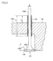
- FIG. 3 shows an exhaust valve as one example.
- a cylindrical sleeve 104 is fixed inside the cylinder head 100.
- the valve rod 102a of the exhaust valve 102 is slidably guided in the sleeve 104.
- the valve member 102b of the exhaust valve 102 rests on a valve seat 106 by a resilient force of a coil spring (not shown), and moves away from the valve seat 106 by the action of a cam (not shown), thus opening and closing the exhaust port 108.
- the sleeve 104 protrudes from the upper surface (reference surface) 100a of the cylinder head 100 by an amount L 0 , which is more than twice the outer diameter of the valve rod, and the entire length L 1 of the sleeve is more than six times the outer diameter S of the valve rod. This restricts inclination of the valve rod 102a so that the exhaust valve 102 does not contact the valve seat 106 on one side only, whereby uneven wear on the exhaust valve 102 and the valve seat 106 is prevented.
- Patent Document 1 cannot effectively be applied for exhaust valves.
- Patent Document 2 The means disclosed in Patent Document 2 is not based on the fact that the uneven flow of intake air or combustion exhaust gas around the valve member is the major cause of uneven wear on the valve member or the valve seat. Thus, it does not provide a fundamental solution to prevent uneven wear.
- an object of the present invention is to prevent uneven wear in an internal combustion engine, which is particularly severe on the exhaust valve, to reduce the frequency of replacing the exhaust valve or its valve seat.
- the present invention provides a cylinder structure for an internal combustion engine having a cylinder head including an exhaust valve and a sleeve that slidably guides an exhaust valve rod, the cylinder structure satisfying the following conditions: 12% ⁇ d/a ⁇ 27%, where d is a distance between an inner surface of the cylinder and an exhaust valve member and a is a diameter of the exhaust valve member; 40% ⁇ c/b ⁇ 50%, where c is a length of a non-guided portion of the exhaust valve located below a lower end of the sleeve when the exhaust valve is closed, and b is a diameter of a cylinder bore; and 0.5% ⁇ e/S ⁇ 0.8%, where e is a gap between the exhaust valve rod and the sleeve and S is a diameter of the exhaust valve rod.
- the present inventors found out that unevenness in the flow around the exhaust valve member occurred in conventional cylinders because the distance d between the cylinder inner surface and the exhaust valve member was small. Therefore, in the present invention, the distance d is increased so that 12% ⁇ d/a, to prevent formation of an uneven flow. If the ratio d/a is to exceed 27%, the exhaust valve member need to have a smaller diameter and the cylinder bore need to have a larger diameter, which will render the cylinder unable to exhibit desired design performance. Thus the upper limit of d/a is 27%.
- the ratio of the length c of the non-guided portion of the exhaust valve located below the lower end of the sleeve to the cylinder bore diameter b is set not to exceed 50% (c/b ⁇ 50%), to shorten the non-guided region of the exhaust valve rod. This restricts inclination of the exhaust valve rod below the sleeve to prevent the exhaust valve member from contacting the valve seat on one side only.
- the ratio c/b being less than 40% means that the sleeve will protrude into the exhaust port, which will hinder the flow of the exhaust gas.
- the lower limit of c/b is 40%.
- the ratio of the gap e between the exhaust valve rod and the sleeve to the outer diameter S of the exhaust valve rod is set in the range of 0.5% ⁇ e/S ⁇ 0.8%. Reducing the gap e restricts inclination of the exhaust valve rod and prevents the exhaust valve member from contacting the valve seat on one side only.
- the ratio e/S being less than 0.5% means that the sleeve or the exhaust valve rod may suffer thermal deformation, or that carbonized substance or the like may deposit between the sleeve and the exhaust valve member, which may impede smooth sliding of the exhaust valve rod.
- the lower limit of e/S is 0.5%.
- the cylinder structure for an internal combustion engine having a cylinder head including an exhaust valve and a sleeve that slidably guides an exhaust valve rod satisfies 12% ⁇ d/a ⁇ 27%, where d is a distance between an inner surface of the cylinder and an exhaust valve member and a is a diameter of the exhaust valve member; 40% ⁇ c/b ⁇ 50%, where c is a length of a non-guided portion of the exhaust valve located below a lower end of the sleeve when the exhaust valve is closed, and b is a diameter of a cylinder bore; and 0.5% ⁇ e/S ⁇ 0.8%, where e is a gap between the exhaust valve rod and the sleeve and S is a diameter of the exhaust valve rod.
- FIG. 1 shows a cylinder head part of a diesel engine according to this embodiment.
- a cylinder head 10 is mounted on a cylinder 12.
- the cylinder head 10 has an intake port 14 and an exhaust port 16.
- the intake port 14 and the exhaust port 16 open into the cylinder bore, and an intake valve 18 and an exhaust valve 20 are mounted at these openings.
- a valve seat 22 for a valve member 18a of the intake valve 18 to rest on, and a valve seat 24 for a valve member 20b of the exhaust valve 20 to rest on, are provided around the openings for the intake port 14 and the exhaust port 16.
- a cylindrical sleeve 26 is secured vertically in a hole drilled in a casing 10a of the cylinder head 10.
- An exhaust valve rod 20a is arranged inside the sleeve 26 such as to be slidable.
- a coil spring 28 disposed on the upper surface of the casing 10a applies a resilient force on the exhaust valve member 20b so that the valve member rests on the valve seat 24 to close the exhaust port 16.
- a rocker arm 30 is operated to move the exhaust valve rod 20a downward.
- the intake valve 18 has a similar open/close mechanism.
- the distance d between the cylinder inner surface 12a and the exhaust valve member 20b is made larger than that of conventional designs, so that the ratio of the distance d to the diameter a of the exhaust valve member 20b is equal to or more than 12% 12% ⁇ d/a).
- the ratio d/a exceeding 27% means that the exhaust valve member 20b need to have a smaller diameter a and the cylinder bore need to have a larger diameter b.
- the cylinder 12 could then not exhibit desired combustion performance.
- the upper limit of d/a is 27%.
- the length c of a non-guided portion of the exhaust valve rod 20a located below the lower end of the sleeve 26 when the valve is closed is made shorter than that of conventional designs, so that the ratio of this length c to the cylinder bore diameter b does not exceed 50% (c/b ⁇ 50%).
- the ratio c/b being less than 40% means that the lower end of the sleeve 26 will protrude into the exhaust port 16. The sleeve 26 would then hinder the flow of the combustion exhaust gas in the exhaust port 16.
- the lower limit of c/b is 40%.
- the gap e between the sleeve 26 and the exhaust valve rod 20a is made smaller so that the ratio of the gap e to the outer diameter S of the exhaust valve rod 20a does not exceed 0.80 (e/S ⁇ 0.8%). This restricts inclination of the exhaust valve rod 20a and prevents the exhaust valve member 20b from contacting the valve seat 24 on one side only.
- the ratio e/S being less than 0.5% means that the sleeve 26 or the exhaust valve rod 20a may suffer thermal deformation, or that foreign matter such as carbonized substance may enter the gap e and impede smooth sliding of the exhaust valve rod 20a inside the sleeve 26.
- the lower limit of e/S is 0.5%.
- the exhaust valve rod 20a may tilt enough to cause the exhaust valve member 20b to contact the valve seat 24 on one side, which may possibly cause uneven wear on the exhaust valve member 20b and the valve seat 24.
- the present inventors fabricated cylinder heads in accordance with this embodiment with the components including the intake and exhaust valves of varying sizes. These cylinder heads were installed in a gas engine and subjected to an actual combustion test, with city gas 13A used as fuel. In the combustion test, the engine was operated at rated conditions for 5,000 hours, after which the pressure inside the cylinder during the compression stroke before the combustion stroke was detected with an in-cylinder pressure sensor, and the temperature of the combustion exhaust gas that has passed through the exhaust valve was detected with a temperature sensor.
- the in-cylinder pressure in the compression stroke is 7.0 to 8.0 MPa in normal operation. If there is a leak in the exhaust valve due to uneven wear on the exhaust valve member 20b or the like, there is a pressure drop of about 0.3 to 0.5 MPa.
- the temperature of the compression exhaust gas is about 500°C in normal operation. If there is a leak in the exhaust valve due to uneven wear on the exhaust valve member 20b or the like, there is a temperature drop of 20 to 30°C. In this combustion test, the pressure and temperature are monitored for a drop to determine whether or not there is a leak in the exhaust valve.
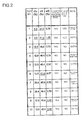
- FIG. 2 shows the results. In the columns of d/a, c/b, and e/S in FIG. 2 , the values out of the above-mentioned ranges of the present invention are underlined.
- cylinders having other structures than the one shown in FIG. 2 were used, too. Namely, one of the cylinders used in the combustion test had the ratio d/a of more than the upper limit of 27%. Although no unevenness was observed in the flow around the exhaust valve member in the combustion test, the cylinder bore diameter b, the diameter a of the exhaust valve member, and the like did not satisfy design conditions. Therefore, the cylinder was not able to exhibit its desired combustion performance.
Landscapes
- Engineering & Computer Science (AREA)
- Mechanical Engineering (AREA)
- General Engineering & Computer Science (AREA)
- Chemical & Material Sciences (AREA)
- Combustion & Propulsion (AREA)
- Cylinder Crankcases Of Internal Combustion Engines (AREA)
- Valve-Gear Or Valve Arrangements (AREA)
Abstract
Description
- The present invention relates to a cylinder structure that can prevent uneven wear on a valve member and a valve seat of an exhaust valve in an internal combustion engine.
- In an intake or exhaust vale provided in a cylinder head of an internal combustion engine, the flow of intake air or combustion exhaust gas around the valve members becomes uneven when the intake or exhaust valve is opened. The uneven flow of gas applies a bending stress on the valve members, causing the valve members to contact the valve seats on one side only. Such one-sided contact causes uneven wear on the valve members and the valve seats. The uneven wear may lead to a flow leak between the intake or exhaust valve and the valve seat, in which case the intake or exhaust valve or the valve seat must be replaced.
- The exhaust valve, in particular, tends to contact the valve seat on one side only, as it is exposed to high temperature combustion gas flowing therearound so that the valve member and the valve seat are prone to thermal deformation or thermal degradation. Uneven flow or scoring is also caused by carbonized fuel residue adhering on the valve member or the valve seat. Such carbonized substance adhering and depositing between a valve rod and a sleeve that slidably guides the valve rod will hinder smooth sliding of the valve rod.
- Moreover, since the combustion gas passing through the exhaust valve has a higher pressure than the intake air through the intake valve, the exhaust valve is subjected to a high bending stress. This bending stress also causes the valve to contact the seat on one side only. Furthermore, when the combustion exhaust gas exits from the cylinder through the exhaust valve into the exhaust port, turbulence is easily generated because the lower surface of the exhaust valve member is not streamlined. Such turbulence also causes uneven flow of gas.
-
Patent Document 1 andPatent Document 2 disclose means of preventing uneven wear on an intake or exhaust valve and the valve seat in internal combustion engines. The means disclosed inPatent Document 1 is comprised of a plurality of circumferentially spaced grooves on the surface of a valve member facing the intake or exhaust port. Swirls of intake or exhaust gas passing through the intake or exhaust port are blown to these grooves to rotate the intake or exhaust valve by the turning motion of the swirls(sic), to prevent uneven wear on the intake or exhaust valve and the valve seat. - The means disclosed in
Patent Document 2 is built upon the design of a cylindrical sleeve that slidably guides an intake or exhaust valve. This means will be described below with reference toFIG. 3 (FIG. 1 of Patent Document 2).FIG. 3 shows an exhaust valve as one example. Acylindrical sleeve 104 is fixed inside thecylinder head 100. Thevalve rod 102a of theexhaust valve 102 is slidably guided in thesleeve 104. Thevalve member 102b of theexhaust valve 102 rests on avalve seat 106 by a resilient force of a coil spring (not shown), and moves away from thevalve seat 106 by the action of a cam (not shown), thus opening and closing theexhaust port 108. - The
sleeve 104 protrudes from the upper surface (reference surface) 100a of thecylinder head 100 by an amount L0, which is more than twice the outer diameter of the valve rod, and the entire length L1 of the sleeve is more than six times the outer diameter S of the valve rod. This restricts inclination of thevalve rod 102a so that theexhaust valve 102 does not contact thevalve seat 106 on one side only, whereby uneven wear on theexhaust valve 102 and thevalve seat 106 is prevented. -
- Patent Document 1: Japanese Utility Model Application Laid-open No.
H6-34101 - Patent Document 2: Japanese Utility Model Application Laid-open No.
H6-37507 - If carbonized substance adheres on the valve rod or the valve seat, or deposits between the sleeve and the valve rod, the turning motion of swirls may not be sufficient to rotate the exhaust valve. Therefore, the means disclosed in
Patent Document 1 cannot effectively be applied for exhaust valves. - The means disclosed in
Patent Document 2 is not based on the fact that the uneven flow of intake air or combustion exhaust gas around the valve member is the major cause of uneven wear on the valve member or the valve seat. Thus, it does not provide a fundamental solution to prevent uneven wear. - In view of these problems in the conventional techniques, an object of the present invention is to prevent uneven wear in an internal combustion engine, which is particularly severe on the exhaust valve, to reduce the frequency of replacing the exhaust valve or its valve seat.
- To achieve the object, the present invention provides a cylinder structure for an internal combustion engine having a cylinder head including an exhaust valve and a sleeve that slidably guides an exhaust valve rod, the cylinder structure satisfying the following conditions: 12% ≤ d/a ≤ 27%, where d is a distance between an inner surface of the cylinder and an exhaust valve member and a is a diameter of the exhaust valve member; 40% ≤ c/b ≤ 50%, where c is a length of a non-guided portion of the exhaust valve located below a lower end of the sleeve when the exhaust valve is closed, and b is a diameter of a cylinder bore; and 0.5% ≤ e/S ≤ 0.8%, where e is a gap between the exhaust valve rod and the sleeve and S is a diameter of the exhaust valve rod.
- The present inventors found out that unevenness in the flow around the exhaust valve member occurred in conventional cylinders because the distance d between the cylinder inner surface and the exhaust valve member was small. Therefore, in the present invention, the distance d is increased so that 12% ≤ d/a, to prevent formation of an uneven flow. If the ratio d/a is to exceed 27%, the exhaust valve member need to have a smaller diameter and the cylinder bore need to have a larger diameter, which will render the cylinder unable to exhibit desired design performance. Thus the upper limit of d/a is 27%.
- The ratio of the length c of the non-guided portion of the exhaust valve located below the lower end of the sleeve to the cylinder bore diameter b is set not to exceed 50% (c/b ≤ 50%), to shorten the non-guided region of the exhaust valve rod. This restricts inclination of the exhaust valve rod below the sleeve to prevent the exhaust valve member from contacting the valve seat on one side only. The ratio c/b being less than 40% means that the sleeve will protrude into the exhaust port, which will hinder the flow of the exhaust gas. Thus, the lower limit of c/b is 40%.
- The ratio of the gap e between the exhaust valve rod and the sleeve to the outer diameter S of the exhaust valve rod is set in the range of 0.5% ≤ e/S ≤ 0.8%. Reducing the gap e restricts inclination of the exhaust valve rod and prevents the exhaust valve member from contacting the valve seat on one side only. The ratio e/S being less than 0.5% means that the sleeve or the exhaust valve rod may suffer thermal deformation, or that carbonized substance or the like may deposit between the sleeve and the exhaust valve member, which may impede smooth sliding of the exhaust valve rod. Thus, the lower limit of e/S is 0.5%.
- According to the present invention, the cylinder structure for an internal combustion engine having a cylinder head including an exhaust valve and a sleeve that slidably guides an exhaust valve rod satisfies 12% ≤ d/a ≤ 27%, where d is a distance between an inner surface of the cylinder and an exhaust valve member and a is a diameter of the exhaust valve member; 40% ≤ c/b ≤ 50%, where c is a length of a non-guided portion of the exhaust valve located below a lower end of the sleeve when the exhaust valve is closed, and b is a diameter of a cylinder bore; and 0.5% ≤ e/S ≤ 0.8%, where e is a gap between the exhaust valve rod and the sleeve and S is a diameter of the exhaust valve rod. Therefore, there is less unevenness in the flow of combustion gas flowing around the exhaust valve member, which prevents the exhaust valve member from contacting the valve seat on one side only. Thus there will be no uneven wear on the exhaust valve member and the valve seat so that the exhaust valve member and the valve seat can have longer life and the frequency of replacing these components will be reduced.
-
-
FIG. 1 is a cross-sectional view of a cylinder head according to one embodiment of the apparatus of the present invention; -
FIG. 2 is a table showing the results of a combustion test conducted on the cylinder head and (non-published) comparative examples; and -
FIG. 3 is a cross-sectional view of a conventional cylinder head. - The illustrated embodiment of the present invention will be hereinafter described in detail. It should be noted that, unless otherwise particularly specified, the sizes, materials, shapes, and relative arrangement or the like of constituent components described in this embodiment are not intended to limit the scope of this invention.
- One embodiment of the apparatus of the present invention will be described with reference to experimental data and
FIG. 1 andFIG. 2 .FIG. 1 shows a cylinder head part of a diesel engine according to this embodiment. InFIG. 1 , acylinder head 10 is mounted on acylinder 12. Thecylinder head 10 has anintake port 14 and anexhaust port 16. Theintake port 14 and theexhaust port 16 open into the cylinder bore, and anintake valve 18 and anexhaust valve 20 are mounted at these openings. - A valve seat 22 for a
valve member 18a of theintake valve 18 to rest on, and avalve seat 24 for avalve member 20b of theexhaust valve 20 to rest on, are provided around the openings for theintake port 14 and theexhaust port 16. Acylindrical sleeve 26 is secured vertically in a hole drilled in acasing 10a of thecylinder head 10. Anexhaust valve rod 20a is arranged inside thesleeve 26 such as to be slidable. - A
coil spring 28 disposed on the upper surface of thecasing 10a applies a resilient force on theexhaust valve member 20b so that the valve member rests on thevalve seat 24 to close theexhaust port 16. To open theexhaust port 16, arocker arm 30 is operated to move theexhaust valve rod 20a downward. Theintake valve 18 has a similar open/close mechanism. - In this embodiment, the distance d between the cylinder
inner surface 12a and theexhaust valve member 20b is made larger than that of conventional designs, so that the ratio of the distance d to the diameter a of theexhaust valve member 20b is equal to or more than 12% 12% ≤ d/a). This allows the combustion exhaust gas g flowing around theexhaust valve member 20b to flow uniformly around theexhaust valve member 20b when theexhaust valve 20 is opened. The ratio d/a exceeding 27% means that theexhaust valve member 20b need to have a smaller diameter a and the cylinder bore need to have a larger diameter b. Thecylinder 12 could then not exhibit desired combustion performance. Thus the upper limit of d/a is 27%. - The length c of a non-guided portion of the
exhaust valve rod 20a located below the lower end of thesleeve 26 when the valve is closed is made shorter than that of conventional designs, so that the ratio of this length c to the cylinder bore diameter b does not exceed 50% (c/b ≤ 50%). This restricts inclination of theexhaust valve rod 20a below thesleeve 26 and prevents theexhaust valve member 20b from contacting thevalve seat 24 on one side only. The ratio c/b being less than 40% means that the lower end of thesleeve 26 will protrude into theexhaust port 16. Thesleeve 26 would then hinder the flow of the combustion exhaust gas in theexhaust port 16. Thus, the lower limit of c/b is 40%. - The gap e between the
sleeve 26 and theexhaust valve rod 20a is made smaller so that the ratio of the gap e to the outer diameter S of theexhaust valve rod 20a does not exceed 0.80 (e/S ≤ 0.8%). This restricts inclination of theexhaust valve rod 20a and prevents theexhaust valve member 20b from contacting thevalve seat 24 on one side only. The ratio e/S being less than 0.5% means that thesleeve 26 or theexhaust valve rod 20a may suffer thermal deformation, or that foreign matter such as carbonized substance may enter the gap e and impede smooth sliding of theexhaust valve rod 20a inside thesleeve 26. Thus, the lower limit of e/S is 0.5%. - With the ratio e/S exceeding 0.8%, the
exhaust valve rod 20a may tilt enough to cause theexhaust valve member 20b to contact thevalve seat 24 on one side, which may possibly cause uneven wear on theexhaust valve member 20b and thevalve seat 24. - According to this embodiment, with this structure, as the distance d is increased, there is no unevenness in the flow of combustion gas g around the
exhaust valve member 20b when theexhaust port 16 is opened. With the length c of the non-guided portion below thesleeve 26 being shortened and with the gap e being reduced, tilting of theexhaust valve rod 20a is restricted. Therefore theexhaust valve member 20b does not contact thevalve seat 24 on one side only. Thus there will be no uneven wear on theexhaust valve member 20b and thevalve seat 24 so that they can have longer life. - The present inventors fabricated cylinder heads in accordance with this embodiment with the components including the intake and exhaust valves of varying sizes. These cylinder heads were installed in a gas engine and subjected to an actual combustion test, with city gas 13A used as fuel. In the combustion test, the engine was operated at rated conditions for 5,000 hours, after which the pressure inside the cylinder during the compression stroke before the combustion stroke was detected with an in-cylinder pressure sensor, and the temperature of the combustion exhaust gas that has passed through the exhaust valve was detected with a temperature sensor.
- The in-cylinder pressure in the compression stroke is 7.0 to 8.0 MPa in normal operation. If there is a leak in the exhaust valve due to uneven wear on the
exhaust valve member 20b or the like, there is a pressure drop of about 0.3 to 0.5 MPa. The temperature of the compression exhaust gas is about 500°C in normal operation. If there is a leak in the exhaust valve due to uneven wear on theexhaust valve member 20b or the like, there is a temperature drop of 20 to 30°C. In this combustion test, the pressure and temperature are monitored for a drop to determine whether or not there is a leak in the exhaust valve. - Cylinders with d/a, c/b, and e/S within the ranges of the present invention, and cylinders with these ratios out of the ranges of the present invention (comparative examples) were both examined in the combustion test.
FIG. 2 shows the results. In the columns of d/a, c/b, and e/S inFIG. 2 , the values out of the above-mentioned ranges of the present invention are underlined. - As shown in
FIG. 2 , there is a drop in at least one of the in-cylinder pressure in the compression stroke and the temperature of the exhaust gas in the comparative examples. This indicates that there was a flow leak in the exhaust valve of the comparative examples. On the other hand, neither of these phenomena occurred in the cylinder structures according to the present invention. This indicates that there was no flow leak in the exhaust valve of the cylinder structures of the present invention. - In the combustion test conducted by the present inventors, cylinders having other structures than the one shown in
FIG. 2 were used, too. Namely, one of the cylinders used in the combustion test had the ratio d/a of more than the upper limit of 27%. Although no unevenness was observed in the flow around the exhaust valve member in the combustion test, the cylinder bore diameter b, the diameter a of the exhaust valve member, and the like did not satisfy design conditions. Therefore, the cylinder was not able to exhibit its desired combustion performance. - Another cylinder used in the combustion test had the ratio c/b of less than the lower limit of 40%. The combustion test revealed a problem that the lower region of the
sleeve 26 protruding into theexhaust port 16 impeded the flow of combustion exhaust gas flowing inside theexhaust port 16. - According to the present invention, uneven wear on the exhaust valve and the valve seat of internal combustion engines is prevented so that these components can have longer life.
Claims (1)
- A cylinder structure for an internal combustion engine comprising a cylinder head having an exhaust valve and a sleeve that slidably guides an exhaust valve rod, the cylinder structure satisfying the following conditions:

where d is a distance between an inner surface of the cylinder and an exhaust valve member and a is a diameter of the exhaust valve member;
where c is a length of a non-guided portion of the exhaust valve located below a lower end of the sleeve when the exhaust valve is closed, and b is a diameter of a cylinder bore; and
where e is a gap between the exhaust valve rod and the sleeve and S is a diameter of the exhaust valve rod.
Applications Claiming Priority (2)
| Application Number | Priority Date | Filing Date | Title |
|---|---|---|---|
| JP2011080417A JP5342592B2 (en) | 2011-03-31 | 2011-03-31 | Cylinder structure of internal combustion engine |
| PCT/JP2011/072640 WO2012132070A1 (en) | 2011-03-31 | 2011-09-30 | Cylinder structure of internal combustion engine |
Publications (3)
| Publication Number | Publication Date |
|---|---|
| EP2693005A1 true EP2693005A1 (en) | 2014-02-05 |
| EP2693005A4 EP2693005A4 (en) | 2014-10-22 |
| EP2693005B1 EP2693005B1 (en) | 2017-03-22 |
Family
ID=46929875
Family Applications (1)
| Application Number | Title | Priority Date | Filing Date |
|---|---|---|---|
| EP11862012.9A Active EP2693005B1 (en) | 2011-03-31 | 2011-09-30 | Cylinder structure of internal combustion engine |
Country Status (6)
| Country | Link |
|---|---|
| US (1) | US9080531B2 (en) |
| EP (1) | EP2693005B1 (en) |
| JP (1) | JP5342592B2 (en) |
| KR (1) | KR101481932B1 (en) |
| CN (1) | CN103429858B (en) |
| WO (1) | WO2012132070A1 (en) |
Families Citing this family (2)
| Publication number | Priority date | Publication date | Assignee | Title |
|---|---|---|---|---|
| EP3217316A1 (en) * | 2016-03-11 | 2017-09-13 | Nxp B.V. | Fingerprint sensing system and method |
| CN110863876A (en) * | 2019-11-27 | 2020-03-06 | 厦门林巴贺航空发动机股份有限公司 | Aero-engine valve push rod sleeve and valve push rod mechanism |
Family Cites Families (28)
| Publication number | Priority date | Publication date | Assignee | Title |
|---|---|---|---|---|
| US2123302A (en) * | 1937-03-23 | 1938-07-12 | Clarence C Groth | Internal combustion engine |
| US2814283A (en) * | 1954-04-12 | 1957-11-26 | Daimler Benz Ag | Valve control mechanism, particularly for high speed internal combustion engines |
| US3503375A (en) * | 1968-06-17 | 1970-03-31 | Thompson Mfg Co Earl A | Valve |
| DE1751960A1 (en) * | 1968-08-24 | 1971-09-02 | Maschf Augsburg Nuernberg Ag | Valve, in particular inlet valve for internal combustion engines |
| GB1521957A (en) | 1976-04-24 | 1978-08-23 | Toyo Kogyo Co | Cylinder head construction for an internal combustion engine |
| JPS55132339U (en) * | 1979-03-14 | 1980-09-19 | ||
| JPS55132339A (en) | 1979-04-02 | 1980-10-15 | Yasuhira Katabami | Method and apparatus to turn on and off car door alarm lamp |
| JPH02130206A (en) * | 1988-11-07 | 1990-05-18 | Aisan Ind Co Ltd | Cooling device for exhaust valve |
| GB8928386D0 (en) * | 1989-12-15 | 1990-02-21 | Ricardo Group Plc | Internal combustion engine |
| US5230310A (en) * | 1991-03-29 | 1993-07-27 | Mazda Motor Corporation | Combustion chamber of internal combustion engine |
| JPH0637507A (en) | 1992-07-20 | 1994-02-10 | Japan Radio Co Ltd | Dielectric filter |
| JP3343787B2 (en) | 1992-07-21 | 2002-11-11 | 株式会社荏原製作所 | Device for preventing overheating of forced circulation section in forced circulation boiler |
| JPH0634101U (en) | 1992-10-07 | 1994-05-06 | 日産ディーゼル工業株式会社 | Engine intake and exhaust valves |
| JPH0637507U (en) * | 1992-10-14 | 1994-05-20 | 日産ディーゼル工業株式会社 | Intake and exhaust valves for internal combustion engines |
| JPH0914047A (en) * | 1995-06-23 | 1997-01-14 | Yamaha Motor Co Ltd | Exhaust port structure of engine |
| JP3328502B2 (en) * | 1996-04-23 | 2002-09-24 | 株式会社ユニシアジェックス | Valve lifter for internal combustion engine |
| DE19734007A1 (en) * | 1997-08-06 | 1999-02-11 | Deutz Ag | Cylinder head for use with crankcases with different cylinder bore diameters |
| JPH11159396A (en) * | 1997-11-27 | 1999-06-15 | Mitsubishi Motors Corp | Internal combustion engine |
| US6125809A (en) * | 1998-10-20 | 2000-10-03 | Caterpillar Inc. | Valve redesign for improved life |
| DE19928838C1 (en) * | 1999-06-24 | 2001-02-15 | Otmar Gaehrken | Cylinder head |
| JP2001234715A (en) * | 2000-02-24 | 2001-08-31 | Mitsubishi Heavy Ind Ltd | Valve seat for internal combustion engine |
| JP3814462B2 (en) * | 2000-05-30 | 2006-08-30 | 株式会社日立製作所 | Valve lifter for internal combustion engine |
| US7069883B2 (en) * | 2000-10-19 | 2006-07-04 | Atkins Robert M | Monitoring of closed circuit liquid cooling systems particularly in internal combustion engines |
| US6408803B1 (en) * | 2000-10-19 | 2002-06-25 | Robert M. Atkins | Liquid cooling system and retrofit for horizontally opposed air cooled piston aircraft engines |
| JP2002317613A (en) * | 2001-04-20 | 2002-10-31 | Mitsubishi Electric Corp | Valve lift adjustment device |
| JP4024018B2 (en) * | 2001-07-06 | 2007-12-19 | 本田技研工業株式会社 | 4-stroke internal combustion engine cylinder head |
| WO2006108438A1 (en) * | 2005-04-14 | 2006-10-19 | Man B & W Diesel A/S | Exhaust valve assembly for a large two-stroke diesel engine |
| JP5036799B2 (en) | 2009-12-21 | 2012-09-26 | 川崎重工業株式会社 | 4-stroke internal combustion engine |
-
2011
- 2011-03-31 JP JP2011080417A patent/JP5342592B2/en active Active
- 2011-09-30 CN CN201180069438.XA patent/CN103429858B/en active Active
- 2011-09-30 US US14/003,330 patent/US9080531B2/en active Active
- 2011-09-30 EP EP11862012.9A patent/EP2693005B1/en active Active
- 2011-09-30 WO PCT/JP2011/072640 patent/WO2012132070A1/en not_active Ceased
- 2011-09-30 KR KR20137025171A patent/KR101481932B1/en not_active Expired - Fee Related
Also Published As
| Publication number | Publication date |
|---|---|
| EP2693005A4 (en) | 2014-10-22 |
| WO2012132070A1 (en) | 2012-10-04 |
| EP2693005B1 (en) | 2017-03-22 |
| JP5342592B2 (en) | 2013-11-13 |
| CN103429858A (en) | 2013-12-04 |
| KR20130127521A (en) | 2013-11-22 |
| KR101481932B1 (en) | 2015-01-12 |
| JP2012215105A (en) | 2012-11-08 |
| CN103429858B (en) | 2016-01-20 |
| US20140014058A1 (en) | 2014-01-16 |
| US9080531B2 (en) | 2015-07-14 |
Similar Documents
| Publication | Publication Date | Title |
|---|---|---|
| US7862048B2 (en) | Gasket for a valve in an internal combustion engine | |
| CN105275668B (en) | Injectors, especially injection injectors for gaseous fuels | |
| EP2693005B1 (en) | Cylinder structure of internal combustion engine | |
| DE102009042545B4 (en) | engine valves | |
| CN204419288U (en) | For many valve actuations valve cross arm of motor | |
| US20060000432A1 (en) | Wear-resistant slide member and slide device using the same | |
| KR101463800B1 (en) | Gasket | |
| JP2015028322A (en) | Fuel injection valve | |
| US9297332B2 (en) | Cylinder head with annular valve for internal-combustion engine | |
| US20050235949A1 (en) | Gaseous fuel injection valve | |
| CN209925043U (en) | Piston engine valve device with low power consumption and quick response | |
| KR20180136035A (en) | Compressed air recirculation valve | |
| Mantey et al. | Exhaust valve & valve seat insert–development for an industrial LPG application | |
| KR101274239B1 (en) | Intake and exhaust valve for vehicle | |
| KR20090010326A (en) | Exhaust valve of marine engine | |
| CN107002597B (en) | Direct injection gas injector with elastomeric seal | |
| JP2011064124A (en) | Fuel injection valve | |
| US10934901B1 (en) | Valve seat insert for high power density and high speed diesel engines | |
| JP2013108397A (en) | Internal combustion engine valve gear | |
| CN209743053U (en) | Cylinder head of engine, engine and vehicle | |
| JP5867515B2 (en) | Drive device | |
| KR101134385B1 (en) | Damping type valve assembly structure for automobile | |
| CN113302381A (en) | Engine and gas exchange valve with under head fillet contoured for relieving chordal stress | |
| JP2007332920A (en) | Intake control device | |
| CN110608115A (en) | A double spool center rod structure of EGR valve |
Legal Events
| Date | Code | Title | Description |
|---|---|---|---|
| PUAI | Public reference made under article 153(3) epc to a published international application that has entered the european phase |
Free format text: ORIGINAL CODE: 0009012 |
|
| 17P | Request for examination filed |
Effective date: 20130910 |
|
| AK | Designated contracting states |
Kind code of ref document: A1 Designated state(s): AL AT BE BG CH CY CZ DE DK EE ES FI FR GB GR HR HU IE IS IT LI LT LU LV MC MK MT NL NO PL PT RO RS SE SI SK SM TR |
|
| DAX | Request for extension of the european patent (deleted) | ||
| A4 | Supplementary search report drawn up and despatched |
Effective date: 20140923 |
|
| RIC1 | Information provided on ipc code assigned before grant |
Ipc: F01L 3/08 20060101AFI20140917BHEP |
|
| GRAP | Despatch of communication of intention to grant a patent |
Free format text: ORIGINAL CODE: EPIDOSNIGR1 |
|
| INTG | Intention to grant announced |
Effective date: 20161109 |
|
| GRAS | Grant fee paid |
Free format text: ORIGINAL CODE: EPIDOSNIGR3 |
|
| GRAA | (expected) grant |
Free format text: ORIGINAL CODE: 0009210 |
|
| AK | Designated contracting states |
Kind code of ref document: B1 Designated state(s): AL AT BE BG CH CY CZ DE DK EE ES FI FR GB GR HR HU IE IS IT LI LT LU LV MC MK MT NL NO PL PT RO RS SE SI SK SM TR |
|
| REG | Reference to a national code |
Ref country code: GB Ref legal event code: FG4D |
|
| REG | Reference to a national code |
Ref country code: CH Ref legal event code: EP |
|
| REG | Reference to a national code |
Ref country code: AT Ref legal event code: REF Ref document number: 878014 Country of ref document: AT Kind code of ref document: T Effective date: 20170415 |
|
| REG | Reference to a national code |
Ref country code: IE Ref legal event code: FG4D |
|
| REG | Reference to a national code |
Ref country code: DE Ref legal event code: R096 Ref document number: 602011036336 Country of ref document: DE |
|
| REG | Reference to a national code |
Ref country code: NL Ref legal event code: MP Effective date: 20170322 |
|
| PG25 | Lapsed in a contracting state [announced via postgrant information from national office to epo] |
Ref country code: GR Free format text: LAPSE BECAUSE OF FAILURE TO SUBMIT A TRANSLATION OF THE DESCRIPTION OR TO PAY THE FEE WITHIN THE PRESCRIBED TIME-LIMIT Effective date: 20170623 Ref country code: HR Free format text: LAPSE BECAUSE OF FAILURE TO SUBMIT A TRANSLATION OF THE DESCRIPTION OR TO PAY THE FEE WITHIN THE PRESCRIBED TIME-LIMIT Effective date: 20170322 Ref country code: NO Free format text: LAPSE BECAUSE OF FAILURE TO SUBMIT A TRANSLATION OF THE DESCRIPTION OR TO PAY THE FEE WITHIN THE PRESCRIBED TIME-LIMIT Effective date: 20170622 Ref country code: LT Free format text: LAPSE BECAUSE OF FAILURE TO SUBMIT A TRANSLATION OF THE DESCRIPTION OR TO PAY THE FEE WITHIN THE PRESCRIBED TIME-LIMIT Effective date: 20170322 |
|
| REG | Reference to a national code |
Ref country code: LT Ref legal event code: MG4D |
|
| PG25 | Lapsed in a contracting state [announced via postgrant information from national office to epo] |
Ref country code: SE Free format text: LAPSE BECAUSE OF FAILURE TO SUBMIT A TRANSLATION OF THE DESCRIPTION OR TO PAY THE FEE WITHIN THE PRESCRIBED TIME-LIMIT Effective date: 20170322 Ref country code: RS Free format text: LAPSE BECAUSE OF FAILURE TO SUBMIT A TRANSLATION OF THE DESCRIPTION OR TO PAY THE FEE WITHIN THE PRESCRIBED TIME-LIMIT Effective date: 20170322 Ref country code: BG Free format text: LAPSE BECAUSE OF FAILURE TO SUBMIT A TRANSLATION OF THE DESCRIPTION OR TO PAY THE FEE WITHIN THE PRESCRIBED TIME-LIMIT Effective date: 20170622 Ref country code: LV Free format text: LAPSE BECAUSE OF FAILURE TO SUBMIT A TRANSLATION OF THE DESCRIPTION OR TO PAY THE FEE WITHIN THE PRESCRIBED TIME-LIMIT Effective date: 20170322 |
|
| PG25 | Lapsed in a contracting state [announced via postgrant information from national office to epo] |
Ref country code: NL Free format text: LAPSE BECAUSE OF FAILURE TO SUBMIT A TRANSLATION OF THE DESCRIPTION OR TO PAY THE FEE WITHIN THE PRESCRIBED TIME-LIMIT Effective date: 20170322 |
|
| PG25 | Lapsed in a contracting state [announced via postgrant information from national office to epo] |
Ref country code: RO Free format text: LAPSE BECAUSE OF FAILURE TO SUBMIT A TRANSLATION OF THE DESCRIPTION OR TO PAY THE FEE WITHIN THE PRESCRIBED TIME-LIMIT Effective date: 20170322 Ref country code: SK Free format text: LAPSE BECAUSE OF FAILURE TO SUBMIT A TRANSLATION OF THE DESCRIPTION OR TO PAY THE FEE WITHIN THE PRESCRIBED TIME-LIMIT Effective date: 20170322 Ref country code: IT Free format text: LAPSE BECAUSE OF FAILURE TO SUBMIT A TRANSLATION OF THE DESCRIPTION OR TO PAY THE FEE WITHIN THE PRESCRIBED TIME-LIMIT Effective date: 20170322 Ref country code: CZ Free format text: LAPSE BECAUSE OF FAILURE TO SUBMIT A TRANSLATION OF THE DESCRIPTION OR TO PAY THE FEE WITHIN THE PRESCRIBED TIME-LIMIT Effective date: 20170322 Ref country code: EE Free format text: LAPSE BECAUSE OF FAILURE TO SUBMIT A TRANSLATION OF THE DESCRIPTION OR TO PAY THE FEE WITHIN THE PRESCRIBED TIME-LIMIT Effective date: 20170322 Ref country code: ES Free format text: LAPSE BECAUSE OF FAILURE TO SUBMIT A TRANSLATION OF THE DESCRIPTION OR TO PAY THE FEE WITHIN THE PRESCRIBED TIME-LIMIT Effective date: 20170322 |
|
| PG25 | Lapsed in a contracting state [announced via postgrant information from national office to epo] |
Ref country code: PT Free format text: LAPSE BECAUSE OF FAILURE TO SUBMIT A TRANSLATION OF THE DESCRIPTION OR TO PAY THE FEE WITHIN THE PRESCRIBED TIME-LIMIT Effective date: 20170724 Ref country code: IS Free format text: LAPSE BECAUSE OF FAILURE TO SUBMIT A TRANSLATION OF THE DESCRIPTION OR TO PAY THE FEE WITHIN THE PRESCRIBED TIME-LIMIT Effective date: 20170722 Ref country code: SM Free format text: LAPSE BECAUSE OF FAILURE TO SUBMIT A TRANSLATION OF THE DESCRIPTION OR TO PAY THE FEE WITHIN THE PRESCRIBED TIME-LIMIT Effective date: 20170322 Ref country code: PL Free format text: LAPSE BECAUSE OF FAILURE TO SUBMIT A TRANSLATION OF THE DESCRIPTION OR TO PAY THE FEE WITHIN THE PRESCRIBED TIME-LIMIT Effective date: 20170322 |
|
| REG | Reference to a national code |
Ref country code: DE Ref legal event code: R097 Ref document number: 602011036336 Country of ref document: DE |
|
| PLBE | No opposition filed within time limit |
Free format text: ORIGINAL CODE: 0009261 |
|
| STAA | Information on the status of an ep patent application or granted ep patent |
Free format text: STATUS: NO OPPOSITION FILED WITHIN TIME LIMIT |
|
| PG25 | Lapsed in a contracting state [announced via postgrant information from national office to epo] |
Ref country code: DK Free format text: LAPSE BECAUSE OF FAILURE TO SUBMIT A TRANSLATION OF THE DESCRIPTION OR TO PAY THE FEE WITHIN THE PRESCRIBED TIME-LIMIT Effective date: 20170322 |
|
| 26N | No opposition filed |
Effective date: 20180102 |
|
| PG25 | Lapsed in a contracting state [announced via postgrant information from national office to epo] |
Ref country code: SI Free format text: LAPSE BECAUSE OF FAILURE TO SUBMIT A TRANSLATION OF THE DESCRIPTION OR TO PAY THE FEE WITHIN THE PRESCRIBED TIME-LIMIT Effective date: 20170322 |
|
| REG | Reference to a national code |
Ref country code: CH Ref legal event code: PL |
|
| GBPC | Gb: european patent ceased through non-payment of renewal fee |
Effective date: 20170930 |
|
| PG25 | Lapsed in a contracting state [announced via postgrant information from national office to epo] |
Ref country code: MC Free format text: LAPSE BECAUSE OF FAILURE TO SUBMIT A TRANSLATION OF THE DESCRIPTION OR TO PAY THE FEE WITHIN THE PRESCRIBED TIME-LIMIT Effective date: 20170322 |
|
| REG | Reference to a national code |
Ref country code: IE Ref legal event code: MM4A |
|
| REG | Reference to a national code |
Ref country code: BE Ref legal event code: MM Effective date: 20170930 |
|
| PG25 | Lapsed in a contracting state [announced via postgrant information from national office to epo] |
Ref country code: LU Free format text: LAPSE BECAUSE OF NON-PAYMENT OF DUE FEES Effective date: 20170930 |
|
| REG | Reference to a national code |
Ref country code: FR Ref legal event code: ST Effective date: 20180531 |
|
| PG25 | Lapsed in a contracting state [announced via postgrant information from national office to epo] |
Ref country code: IE Free format text: LAPSE BECAUSE OF NON-PAYMENT OF DUE FEES Effective date: 20170930 Ref country code: CH Free format text: LAPSE BECAUSE OF NON-PAYMENT OF DUE FEES Effective date: 20170930 Ref country code: GB Free format text: LAPSE BECAUSE OF NON-PAYMENT OF DUE FEES Effective date: 20170930 Ref country code: LI Free format text: LAPSE BECAUSE OF NON-PAYMENT OF DUE FEES Effective date: 20170930 |
|
| PG25 | Lapsed in a contracting state [announced via postgrant information from national office to epo] |
Ref country code: BE Free format text: LAPSE BECAUSE OF NON-PAYMENT OF DUE FEES Effective date: 20170930 Ref country code: FR Free format text: LAPSE BECAUSE OF NON-PAYMENT OF DUE FEES Effective date: 20171002 |
|
| PG25 | Lapsed in a contracting state [announced via postgrant information from national office to epo] |
Ref country code: MT Free format text: LAPSE BECAUSE OF NON-PAYMENT OF DUE FEES Effective date: 20170930 |
|
| PG25 | Lapsed in a contracting state [announced via postgrant information from national office to epo] |
Ref country code: HU Free format text: LAPSE BECAUSE OF FAILURE TO SUBMIT A TRANSLATION OF THE DESCRIPTION OR TO PAY THE FEE WITHIN THE PRESCRIBED TIME-LIMIT; INVALID AB INITIO Effective date: 20110930 |
|
| PG25 | Lapsed in a contracting state [announced via postgrant information from national office to epo] |
Ref country code: CY Free format text: LAPSE BECAUSE OF NON-PAYMENT OF DUE FEES Effective date: 20170322 |
|
| PG25 | Lapsed in a contracting state [announced via postgrant information from national office to epo] |
Ref country code: MK Free format text: LAPSE BECAUSE OF FAILURE TO SUBMIT A TRANSLATION OF THE DESCRIPTION OR TO PAY THE FEE WITHIN THE PRESCRIBED TIME-LIMIT Effective date: 20170322 |
|
| PG25 | Lapsed in a contracting state [announced via postgrant information from national office to epo] |
Ref country code: TR Free format text: LAPSE BECAUSE OF FAILURE TO SUBMIT A TRANSLATION OF THE DESCRIPTION OR TO PAY THE FEE WITHIN THE PRESCRIBED TIME-LIMIT Effective date: 20170322 |
|
| PG25 | Lapsed in a contracting state [announced via postgrant information from national office to epo] |
Ref country code: AL Free format text: LAPSE BECAUSE OF FAILURE TO SUBMIT A TRANSLATION OF THE DESCRIPTION OR TO PAY THE FEE WITHIN THE PRESCRIBED TIME-LIMIT Effective date: 20170322 |
|
| PGFP | Annual fee paid to national office [announced via postgrant information from national office to epo] |
Ref country code: FI Payment date: 20250912 Year of fee payment: 15 |
|
| PGFP | Annual fee paid to national office [announced via postgrant information from national office to epo] |
Ref country code: DE Payment date: 20250805 Year of fee payment: 15 |
|
| PGFP | Annual fee paid to national office [announced via postgrant information from national office to epo] |
Ref country code: AT Payment date: 20250827 Year of fee payment: 15 |