EP2692965B1 - Module structure and module construction method - Google Patents
Module structure and module construction method Download PDFInfo
- Publication number
- EP2692965B1 EP2692965B1 EP11862425.3A EP11862425A EP2692965B1 EP 2692965 B1 EP2692965 B1 EP 2692965B1 EP 11862425 A EP11862425 A EP 11862425A EP 2692965 B1 EP2692965 B1 EP 2692965B1
- Authority
- EP
- European Patent Office
- Prior art keywords
- compartment
- equipment component
- modular structure
- equipment
- post
- Prior art date
- Legal status (The legal status is an assumption and is not a legal conclusion. Google has not performed a legal analysis and makes no representation as to the accuracy of the status listed.)
- Not-in-force
Links
- 238000010276 construction Methods 0.000 title claims description 58
- 238000009434 installation Methods 0.000 claims description 15
- 238000000034 method Methods 0.000 description 37
- 238000010586 diagram Methods 0.000 description 34
- 239000004567 concrete Substances 0.000 description 21
- 238000010422 painting Methods 0.000 description 16
- 230000004048 modification Effects 0.000 description 10
- 238000012986 modification Methods 0.000 description 10
- 238000009415 formwork Methods 0.000 description 4
- 238000011900 installation process Methods 0.000 description 4
- 238000005452 bending Methods 0.000 description 3
- 239000000463 material Substances 0.000 description 2
- 238000007591 painting process Methods 0.000 description 2
- 238000000638 solvent extraction Methods 0.000 description 2
- 229910000831 Steel Inorganic materials 0.000 description 1
- 238000004378 air conditioning Methods 0.000 description 1
- 230000000694 effects Effects 0.000 description 1
- 230000002452 interceptive effect Effects 0.000 description 1
- 239000002184 metal Substances 0.000 description 1
- 238000010248 power generation Methods 0.000 description 1
- 230000002265 prevention Effects 0.000 description 1
- 239000011150 reinforced concrete Substances 0.000 description 1
- 230000002787 reinforcement Effects 0.000 description 1
- 239000010959 steel Substances 0.000 description 1
- 238000003466 welding Methods 0.000 description 1
Images







Classifications
-
- G—PHYSICS
- G21—NUCLEAR PHYSICS; NUCLEAR ENGINEERING
- G21D—NUCLEAR POWER PLANT
- G21D1/00—Details of nuclear power plant
-
- E—FIXED CONSTRUCTIONS
- E04—BUILDING
- E04H—BUILDINGS OR LIKE STRUCTURES FOR PARTICULAR PURPOSES; SWIMMING OR SPLASH BATHS OR POOLS; MASTS; FENCING; TENTS OR CANOPIES, IN GENERAL
- E04H5/00—Buildings or groups of buildings for industrial or agricultural purposes
- E04H5/02—Buildings or groups of buildings for industrial purposes, e.g. for power-plants or factories
-
- G—PHYSICS
- G21—NUCLEAR PHYSICS; NUCLEAR ENGINEERING
- G21C—NUCLEAR REACTORS
- G21C21/00—Apparatus or processes specially adapted to the manufacture of reactors or parts thereof
-
- Y—GENERAL TAGGING OF NEW TECHNOLOGICAL DEVELOPMENTS; GENERAL TAGGING OF CROSS-SECTIONAL TECHNOLOGIES SPANNING OVER SEVERAL SECTIONS OF THE IPC; TECHNICAL SUBJECTS COVERED BY FORMER USPC CROSS-REFERENCE ART COLLECTIONS [XRACs] AND DIGESTS
- Y02—TECHNOLOGIES OR APPLICATIONS FOR MITIGATION OR ADAPTATION AGAINST CLIMATE CHANGE
- Y02E—REDUCTION OF GREENHOUSE GAS [GHG] EMISSIONS, RELATED TO ENERGY GENERATION, TRANSMISSION OR DISTRIBUTION
- Y02E30/00—Energy generation of nuclear origin
Definitions
- the present invention relates to a modular structure and a modular construction method using the modular structure, and more particularly, to a modular structure and a modular construction method suitable for plant construction such as atomic power generation.
- a modular structure and a modular construction method as described in the preamble portions of patent claims 1 and 9, respectively, have been known from JP 2000 072379 A (Patent Document 2).
- a plant such as an atomic power plant is housed in a reinforced concrete construction building. This building is partitioned into a plurality of compartments depending on an equipment type or the like. Such a plant construction method of the related art is roughly classified into a process of forming a plurality of compartments by arbitrarily partitioning the plant building whenever equipment is installed and a process of installing pipes/equipment in each of the formed compartments.
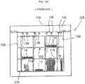
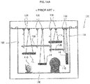
- FIGS. 12A to 12C , 13A to 13C , 14A , and 14B are explanatory diagrams illustrating a plant construction work of the related art.
- FIG. 12A illustrates a sidewall concrete application process.
- FIG. 12B illustrates an equipment loading process.
- FIG. 12C illustrates an equipment component loading process.
- FIG. 13A illustrates a scaffold constructing process.
- FIG. 13B illustrates a ceiling concrete application process.
- FIG. 13C illustrates a hanging tool installation process.
- FIG. 14A illustrates a scaffold removal process.
- FIG. 14B illustrates a painting process.
- a working scaffold 130 for forming sidewalls 108 is assembled in the compartment 104 obtained by partitioning the plant building.
- the working scaffold 130 is removed.
- the equipment 110 provided in the compartment 104 using a large crane from the ceiling surface is loaded as illustrated in FIG. 12B
- an equipment component 14 such as a pipe is loaded as illustrated in FIG. 12C .
- a scaffold 132 for a ceiling work is installed, and an equipment component 14 is temporarily arranged in the scaffold 132. Then, concrete is applied to a formwork on the ceiling surface of the compartment 104 to form a ceiling 134 as illustrated in FIG. 13B . In addition, a hanging tool 136 is installed in the ceiling 134 as illustrated in FIG. 13C .
- the equipment component 14 is hung using the hanging tool 136, and a suspended scaffold 138 is hung using the hanging tool 136.
- a painting work is performed for the sidewall 108 of the compartment 104 using the installed scaffold 132 (or the suspended scaffold 138), and the scaffold 132 is then removed.
- a painting work is performed for the floor surface 106 or a spandrel wall (sidewall 108).
- the painting work is performed for the sidewall 108 or the floor surface 106 of the compartment 104 before the equipment component 14 is fixedly installed in the equipment 110.
- Patent Document 2 JP 2000 072379 A discloses a modular structure comprising: a hanging means that is suitable for hanging a first equipment component arranged in a compartment of a plant and has a length adjusted depending on a layout arrangement position of the first equipment component in the compartment; and a first beam suitable for being arranged in the compartment, the hanging means being installed in the first beam to hang the first equipment component from the first beam.
- This document further discloses a modular construction method comprising: hanging a first equipment component loaded in a compartment of a plant using a hanging means having a length adjusted to match a layout installation position of the first equipment component in the compartment; installing the hanging means in a first beam; and temporarily supporting the first equipment component in the installation position by loading the first beam in the compartment while the first equipment component is hung.
- FIG. 15 is an explanatory diagram illustrating a modular structure disclosed in Patent Document 3.
- Patent Document 3 discloses a modular structure 200 including: a support member 202 that temporarily supports, in a layout position, an equipment component 14 arranged in a compartment and serves as a scaffold for installing the equipment component 14 and forming the compartment; and a box-like frame 204 that can be loaded into an internal space of the compartment and can be used to fix the support member 202.
- a support member 202 that temporarily supports, in a layout position, an equipment component 14 arranged in a compartment and serves as a scaffold for installing the equipment component 14 and forming the compartment
- a box-like frame 204 that can be loaded into an internal space of the compartment and can be used to fix the support member 202.
- Such a technique is also disclosed in Patent Documents 4 and 5.
- the modular structure 200 having the support member 202 and the frame 204 independently stands without interfering with equipment already arranged on the floor surface when the modular structure 200 is arranged in the compartment. Therefore, the equipment component 14 supported by the modular structure 200 is temporarily supported in a layout position in the compartment.
- the modular structure 200 of Patent Document 3 temporarily supports the equipment component 14, it is possible to easily position the equipment component 14 relatively to a base structure such as metal accessories or existing pipes when it is loaded and fixedly installed in the compartment.
- the support member 202 of the modular structure 200 temporarily supports the equipment component 14 and also serves as a scaffold used in both an installation work and a construction work. Therefore, it is possible to perform a construction work of the compartment in parallel with the installation work and eliminate necessity of providing a separate scaffold in the installation position. Accordingly, it is possible to expedite a construction period.
- the invention provides a modular structure and a modular construction method capable of implementing a modular construction work even in an area where equipment pipes are not densely laid out, and the number of temporary installation members increases.
- the invention provides a modular structure and a modular construction method capable of applying a modular construction work in a narrow area and reducing a construction period.
- the invention provides a modular structure and a modular construction method capable of temporarily supporting the equipment component and easily performing a painting work for the floor surface.
- a modular structure including: a hanging means that is hanging a first equipment component adapted to be arranged in a compartment of a plant and has a length adjusted depending on a layout arrangement position of the equipment component in the compartment; and a first beam suitable for being arranged in the compartment, the hanging means being installed in the first beam to hang the first equipment component from the first beam, wherein a suspended scaffold is hung with a hoisting chain from the first beam, and the first equipment component is temporarily supportable in the arrangement position, and the suspended scaffold is used as a scaffold when the first equipment component of the compartment is fixedly installed in a second equipment in the compartment of the plant
- the first beam may be arranged in a sidewall of the compartment and be supported by a support member exposed to an inner space side of the compartment.
- a second beam may be hung from the first beam, and the hanging means may be installed in the first beam and the second beam.
- the first beam may be supported by a post connected to the first beam and erectable on a floor surface of the compartment.
- the second beam may be connected to the post in a position lower than that of the first beam, and the hanging means may be installed in the first beam and the second beam.
- the first beam may be supported by a support member arranged in a sidewall of the compartment and exposed to an inner space side of the compartment and a post connected to the first beam and erectable on a floor surface of the compartment.
- the support member may be arranged only in the other sidewall as described above, and one end of the first beam in a longitudinal direction may be supported by the support member while the other end is supported by the post. Therefore, it is possible to change a method of supporting the beam depending on a situation of the sidewall.
- a center of the first beam in a longitudinal direction may be supported by a second post arranged on a floor surface of the compartment.
- the aforementioned modular structure may further include: a second equipment component arranged right under the first equipment component; and a frame that is arranged to extend across the first equipment component, supports the second equipment component, and is hung by the hanging means.
- a modular construction method including: hanging a first equipment component loaded in a compartment of a plant using a hanging means having a length adjusted to match a layout installation position of the first equipment component in the compartment; installing the hanging means in a first beam; and temporarily supporting the first equipment component in the installation position by loading the first beam in the compartment while the first equipment component is hung, the first equipment component is temporarily supportable in the arrangement position, and a suspended scaffold is hung with a hoisting chain from the first beam, and the suspended scaffold is used as a scaffold, while a sidewall of the compartment is painted.
- the first beam may be supported by a support member arranged in a sidewall of the compartment and exposed to an inner space side of the compartment and/or a post connected to the first beam and erectable on a floor surface of the compartment.
- the support member In a case where the beam is supported by the support member, a plurality of the support members that temporarily support the first equipment component are not arranged on the floor surface. Therefore, it is possible to easily perform a painting work for the floor surface. In addition, in a case where the first beam is supported by the post, it is possible to temporarily support the first equipment component without performing a special work for the sidewall and easily perform a painting work for the floor surface. In addition, for example, in a case where concrete is still applied to one of the sidewalls, or it is difficult to obtain a strength due to a short curing period, the support member is arranged only in the other sidewall, and one end of the beam in the longitudinal direction is supported by the support member while the other end is supported by the post. Therefore, it is possible to change a beam supporting method depending on a forming situation of the sidewall.
- the modular structure and the modular construction method according to the present invention it is possible to temporarily support the equipment component in a layout position of the compartment and suppress interference with the floor surface to the minimum. Therefore, it is possible to efficiently perform a work for the floor surface such as a painting.
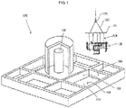
- FIG. 1 is an explanatory diagram illustrating an atomic power plant.
- FIG. 2 is an explanatory diagram illustrating a modular structure according to a first example .
- the atomic power plant 100 includes a reactor pressure vessel 102 in the center and a plurality of equipment units 110.
- a plurality of compartments 104 divided for each equipment unit 110 are formed around the reactor pressure vessel 102.
- Various types of equipment units 110 and a plurality of pipes (equipment components 14) are installed in the compartment 104.
- First, concrete and the like are applied to the floor surface 106 (refer to FIG.
- the equipment component 14 is placed on or hung from a beam 12 extending in a horizontal direction.
- a dimension of the beam 12 is set such that a longitudinal direction of the beam 12 extending in the horizontal direction is fit to the compartment 104.
- the beam 12 is formed of a member having a truss structure having high rigidity against a bending stress.
- the wire rope 16 serving as a hanging means is formed of a steel chain and the like, and one end thereof is connected to the beam 12. In addition, the other end of the wire rope 16 is connected to the equipment component 14.
- the equipment component 14 is temporarily supported by the wire rope 16 in the compartment 104 while it is hung with the wire rope 16. In addition, it is possible to temporarily support the equipment component 14 in a layout position by controlling a length of the wire rope 16. In addition, it is possible to fix a height and a direction of the equipment component 14 by connecting another wire rope 16 in a different position of one equipment component 14.
- the suspended scaffold 18 has a longitudinal direction extending in a horizontal direction. The suspended scaffold 18 is used as a scaffold when the equipment component 14 of the compartment 104 is fixedly installed in the equipment 110 or when the sidewall 108 is painted. The suspended scaffold 18 is hung with a hoisting chain 20 from the beam 12.
- a support member 22 is arranged in the sidewall 108 of the compartment 104.
- the support member 22 is a member embedded into the sidewall 108 of the compartment 104.
- the support member 22 is embedded distant from the ceiling surface such that a worker can walk on the beam 12.
- the support member 22 is arranged to be exposed to the inner space of the compartment 104.
- the support member 22 has the same height across a pair of facing sidewalls 108 of the compartment 104.
- the beam 12 is supported by the support member 22 such that both ends of the beam 12 in a longitudinal direction are provided on the upper surfaces of the support members 22. It is preferable that the support member 22 is arranged when the concrete is applied to the sidewall 108.
- the number of support members 22 may change depending on the number of beams 12 loaded in the compartment 104.
- FIGS. 3A and 3B , 4A and 4B , and 5A and 5B are explanatory diagrams illustrating a construction method using the modular structure according to the first example.
- FIG. 3A illustrates an assembling process.
- FIG. 3B illustrates a delivery process.
- FIG. 4A illustrates a slinging process.
- FIG. 4B illustrates a hoisting process.
- FIG. 5A illustrates a loading process.
- FIG. 5B illustrates a beam installation process.
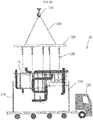
- the modular structure 10 is assembled in a factory 112 or the like located in a different place from that of the atomic power plant 100 where the compartment 104 is provided. Then, the modular structure 10 is delivered using a vehicle 120 and is loaded on the compartment 104 using a large crane.
- the factory 112 includes an overhead crane 114 that hoists the beam 12 and the equipment component 14, a post 116 that supports the beam 12 when the modular structure 10 is assembled and delivered, and a leveling base 118 where the post 116 is erected.
- the post 116 is erected on the leveling base 118.
- the beam 12 where a suspended scaffold 18 is installed in advance is hoisted using the overhead crane 114 and is supported by or connected to the post 116.
- the equipment component 14 is hoisted and is hung from the beam 12 using a wire rope 16 the length of which is adjusted such that the equipment component 14 is temporarily supported in a layout position.
- the equipment component 14 is hung by connecting the wire rope 16 in different positions for each equipment component 14.
- An equipment component 14 laid out in a higher position than that of the beam 12 in the compartment is installed using a tying means (not illustrated) on the beam 12 before the beam 12 is hoisted.
- a structure including the suspended scaffold 18, the equipment component 14, the post 116, and the beam 12 is placed on a cargo deck of a hoist vehicle 120 using the overhead crane 114 and is delivered to the compartment 104 (where a large crane is placed).
- the support member 22 is fixed to the sidewall 108 by embedding the support member 22 in a height position corresponding to the supporting position of the beam 12 as illustrated in FIG. 5A when concrete is applied to the sidewall 108 of the compartment 104.
- the equipment 110 where the equipment component 14 that is supported by the modular structure 10 is connected is loaded in the compartment 104.
- a slinging process using a large crane is performed as illustrated in FIG. 4A .
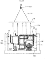
- a balance 126 whose both ends in a longitudinal direction are supported by a wire rope 124 moored in a crane hook 122 provided in the leading end of the large crane so as to keep the longitudinal direction horizontal, and a plurality of chain blocks 128 installed in different positions along the longitudinal direction of the balance 126 are used.
- the wire rope 124, the balance 126, and the chain blocks 128 are integrated into a single body, the wire rope 124 is moored in the crane hook 122, and the chain blocks 128 are connected to the beam 12.
- the beam 12 and the post 116 are disconnected, and the beam 12 is lifted along with the suspended scaffold 18 and the equipment component 14 as illustrated in FIG. 4B . Then, the beam 12 is moved to a position right over the compartment 104 as illustrated in FIG. 5A .
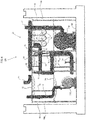
- the crane hook 122 is lowered so that the beam 12 is placed on and connected to the support member 22.
- the beam 12 and the chain block 128 are disconnected, and the equipment component 14 is temporarily fixed to the loaded equipment 110, so that the process of assembling and loading the modular structure 10 is completed.
- the equipment component 14 is temporarily supported in a layout position in the compartment 104.
- a ceiling installation work may be performed by using the beam 12 or the suspended scaffold 18 as a scaffold, or a painting work for the floor surface 106, the sidewall 108, and the like may be performed.
- a painting work for the floor surface 106, the sidewall 108, and the like may be performed.
- FIG. 6 is an explanatory diagram illustrating a modular structure according to a second example, not part of the present invention.
- the modular structure 30 according to the second example commonly uses a structure including the beam 12, the suspended scaffold 18, and the equipment component 14 according to the first example.
- the support member 22 is not arranged in the sidewall 108 of the compartment 104, but the post 32 is erected on the floor surface 106 in a position right under both ends or the center of the longitudinal direction of the beam 12, so that the beam 12 is supported by the post 32.
- the post 32 preferably has a predetermined strength or rigidity similar to that of mine timbering.
- the beam 12 is placed on and connected to the upper end of the post 32. If the beam 12 is supported by the post 32 according to the present example, it is possible to temporarily support the equipment component 14 without performing a special work for the sidewall 108 and easily perform a painting work of the floor surface 106.
- the modular structure 30 according to the second example includes a second beam 34 whose both ends are supported by the post 32 in a position lower than that of the beam 12, so that the equipment component 14 can be installed on the second beam 34.
- a position of the second beam 34 connected to the post 32 is controlled such that the equipment component 14 installed on the second beam 34 is positioned in a layout position in the compartment 104.
- the modular structure 30 including the beam 12, the post 32, the second beam 34, and the equipment component 14 is assembled in the factory 112. Then, the modular structure 30 is delivered and introduced into the compartment 104 using a large crane, so that the modular structure 30 is loaded. Since the post 32 is erected on the floor surface 106, the equipment component 14 can be temporarily supported in a layout position in the compartment 104.
- FIG. 7 is an explanatory diagram illustrating a modular structure according to a third example.
- the support member 22 according to the first example and the post 32 according to the second example are employed while the structure including the beam 12, the suspended scaffold 18, and the equipment component 14 according to the first example is commonly used. That is, one end of the beam 12 in the longitudinal direction is supported by the support member 22, and the other opposite end of the beam 12 in the longitudinal direction is supported by the post 32.
- the equipment 110 and the equipment component 14 are arranged only in a part of the compartment 104 instead of the entire compartment 104.
- the support member 22 may be arranged only in the other of the facing sidewalls 108, and one end of the beam 12 in the longitudinal direction is supported by the support member 22, so that the other end of the beam 12 can be supported by the post 32. Therefore, it is possible to change a method of supporting the beam 12 depending on a forming situation of the sidewall 108.
- the post 32 may be installed in the beam 12 during the assembling process in the factory 112 or may be erected on the floor surface 106 in advance and be connected to the beam 12 when the beam 12 is loaded.
- FIG. 8 is an explanatory diagram illustrating a modular structure according to a fourth example.
- the modular structure 50 according to the fourth example includes a second equipment component 52 arranged right under the equipment component 14 and a frame 54 hung by the wire rope 16 and arranged to extend across the equipment component 14 and support the second equipment component 52.
- the second equipment component 52 is similar to the equipment component 14, the second equipment component 52 is separated from the equipment component 14, and the layout position of the second equipment component 52 is right under the layout position of the equipment component 14. Therefore, since the equipment component 14 is inserted between the beam 12 and the second equipment component 52, it is difficult to hang the second equipment component 14 from the beam 12.
- the second equipment component 52 is hung using the frame 54.
- the frame 54 is obtained by combining a bar-like member with a square box shape, and is arranged such that at least a member 56 corresponding to a top of the square box extends across the equipment component 14. That is, the equipment component 14 is floated inside the square box formed by the frame 54.
- the second equipment component 52 is fixed to, for example, a member 58 corresponding to a bottom of the box shape formed by the frame 54 using an engaging means (not illustrated).
- the wire rope 16 is connected to the frame 54, and the frame 54 is hung from the beam 12.
- the third and fourth examples may be implemented simultaneously.
- FIG. 9 is an explanatory diagram illustrating a first modification of the first example.
- the ceiling may be low, or it may not be necessary to temporarily support the equipment component 14 in a high position.
- the support member 22 may be arranged in a middle height position of the sidewall 108, and the suspended scaffold 18 may not be connected to the beam 12.
- FIG. 10 is an explanatory diagram illustrating a second modification of the first example.
- the center of the beam 12 in the longitudinal direction is supported by the second post 60 arranged in the floor surface 106 of the compartment 104.
- the second post 60 is formed of mine timbering or the like.
- the second post 60 may be installed in the beam 12 when the modular structure 10 is assembled in the factory 112 or may be erected on the floor surface 106 of the compartment 104 in advance. As a result, it is possible to prevent bending of the beam 12 and hang a plurality of equipment components 14 from the beam 12.
- the second posts 60 may be connected to each other using a subsidiary beam 62 to increase rigidity between the second posts 60, and the equipment component 14 may be installed in the subsidiary beam 62.
- This modification may also apply to the second and third embodiments.
- FIG. 11 is an explanatory diagram illustrating a third modification of the first example.
- the second beam 34 is hung from the beam 12 using the hoisting chain 64, and the equipment component 14 is arranged on the second beam 34.
- the equipment component 14 is installed in the beam 12, and the beam 12 is hoisted by the overhead crane 114 (refer to FIG. 3A ) immediately before the second beam 34 is hoisted while the second beam 34 is connected to the beam 12 using the hoisting chain 64.
- the second beam 34 is hoisted, and the beam 12 is placed on and connected to the post 116 (refer to FIG. 3A ).
- another equipment component 14 may be loaded using the overhead crane 114 and may be hung from the beam 12 or the second beam 34 using the wire rope 16.
Landscapes
- Engineering & Computer Science (AREA)
- Architecture (AREA)
- Physics & Mathematics (AREA)
- Plasma & Fusion (AREA)
- General Engineering & Computer Science (AREA)
- High Energy & Nuclear Physics (AREA)
- Civil Engineering (AREA)
- Structural Engineering (AREA)
- Conveying And Assembling Of Building Elements In Situ (AREA)
- Movable Scaffolding (AREA)
Description
- The present invention relates to a modular structure and a modular construction method using the modular structure, and more particularly, to a modular structure and a modular construction method suitable for plant construction such as atomic power generation. A modular structure and a modular construction method as described in the preamble portions of patent claims 1 and 9, respectively, have been known from
JP 2000 072379 A - A plant such as an atomic power plant is housed in a reinforced concrete construction building. This building is partitioned into a plurality of compartments depending on an equipment type or the like. Such a plant construction method of the related art is roughly classified into a process of forming a plurality of compartments by arbitrarily partitioning the plant building whenever equipment is installed and a process of installing pipes/equipment in each of the formed compartments.
-
FIGS. 12A to 12C ,13A to 13C ,14A , and14B are explanatory diagrams illustrating a plant construction work of the related art.FIG. 12A illustrates a sidewall concrete application process.FIG. 12B illustrates an equipment loading process.FIG. 12C illustrates an equipment component loading process.FIG. 13A illustrates a scaffold constructing process.FIG. 13B illustrates a ceiling concrete application process.FIG. 13C illustrates a hanging tool installation process.FIG. 14A illustrates a scaffold removal process.FIG. 14B illustrates a painting process. - As illustrated in
FIG. 12A , in thecompartment 104 obtained by partitioning the plant building, after a concrete application work for afloor surface 106 is completed, a workingscaffold 130 for formingsidewalls 108 is assembled. In addition, after the concrete application to thesidewall 108 is completed, the workingscaffold 130 is removed. Then, theequipment 110 provided in thecompartment 104 using a large crane from the ceiling surface is loaded as illustrated inFIG. 12B , and anequipment component 14 such as a pipe is loaded as illustrated inFIG. 12C . - As illustrated in
FIG. 13A , ascaffold 132 for a ceiling work is installed, and anequipment component 14 is temporarily arranged in thescaffold 132. Then, concrete is applied to a formwork on the ceiling surface of thecompartment 104 to form aceiling 134 as illustrated inFIG. 13B . In addition, ahanging tool 136 is installed in theceiling 134 as illustrated inFIG. 13C . - Then, as illustrated in
FIG. 14A , theequipment component 14 is hung using thehanging tool 136, and a suspendedscaffold 138 is hung using thehanging tool 136. A painting work is performed for thesidewall 108 of thecompartment 104 using the installed scaffold 132 (or the suspended scaffold 138), and thescaffold 132 is then removed. - As illustrated in
FIG. 14B , a painting work is performed for thefloor surface 106 or a spandrel wall (sidewall 108). In this manner, in thecompartment 104, the painting work is performed for thesidewall 108 or thefloor surface 106 of thecompartment 104 before theequipment component 14 is fixedly installed in theequipment 110. - In such a construction method of the related art, the following problems may occur.
- (1) Since the working
scaffold 130 used to apply concrete into a formwork for forming a concrete wall remains in an interior space when thesidewall 108 of thecompartment 104 is constructed, an opening space of the ceiling surface is reduced. Therefore, the workingscaffold 130 used to apply concrete into a formwork for forming a concrete wall and theequipment component 14 hung using the large crane may interfere with each other, so that the amount of materials loaded in thecompartment 104 may be restricted. In addition, since the amount of materials that can be loaded once is restricted, the loading is inevitably performed a plurality of times using a large crane. - (2) When the
equipment 110 is installed in the vicinity of thesidewall 108, it is necessary to move the workingscaffold 130 installed in advance to apply concrete into a formwork for forming a concrete wall and then perform an installation work. Therefore, the work for moving the workingscaffold 130 is frequently performed. Since such a scaffold movement generates an assembling/disassembling work, a construction procedure is interrupted tentatively. - (3) In the loading using a large crane, the
equipment component 14 is temporarily placed on thefloor surface 106. For this reason, as the construction of theequipment 110 advances, it is difficult to obtain a temporary placing room. Therefore, similarly, the construction procedure is interrupted tentatively. - In this manner, in the construction method of the related art, since the concrete application period and the period for loading the
equipment 110 overlap with each other, the construction procedure is significantly affected. - Meanwhile, there is known a construction method that employs a modular structure obtained by installing the equipment component in advance in order to reduce a construction period. A construction method of such a plant facility is disclosed in Patent Documents 1 and 2.
- According to the pipe modular construction method disclosed in Patent Document 1, equipment, pipes, and the like are assembled as a module in an external factory in advance. After a floor of the equipment compartment is constructed, the module is delivered and fixed, and pipes, air-conditioning ducts, and the like are connected. As a result, it is possible to simplify and expedite the construction.
- According to the pipe modular construction method disclosed in Patent Document 2, components are hung from a top plate using a hanging means and are move on a rail while the hanging state is maintained. Then, the components are lifted using a crane and are moved to an installation position.
- However, according to the pipe modular construction method disclosed in Patent Document 1, various apparatuses or pipes are assembled and fixedly installed in installation positions on a fixedly installed operating platform in a factory, and each pipe module is loaded in a construction site and is fixed through welding. For this reason, in a construction site where the fixedly installed operating platform is not laid out in the compartment, it is difficult to set the pipe in a regular position, and there are a lot of areas where it is difficult to apply the modular construction method. In addition, there is a restriction in a size and a weight of the module that can be delivered from a factory, and a delivery cost may increase.
- According to the pipe modular construction method disclosed in Patent Document 2, since a component is hung with the hanging means, it is not necessary to provide an overturning prevention member or a temporary reinforcement member of the component. In addition, it is possible to eliminate an effort to assemble or disassemble components. However, since it is difficult to hang vertically overlapping components using the hanging means, there is a restriction in application. Furthermore, in a case where the components are overlapped in a lot of areas, it is difficult to obtain high positioning accuracy.
- Patent Document 2 (
JP 2000 072379 A - This document further discloses a modular construction method comprising: hanging a first equipment component loaded in a compartment of a plant using a hanging means having a length adjusted to match a layout installation position of the first equipment component in the compartment; installing the hanging means in a first beam; and temporarily supporting the first equipment component in the installation position by loading the first beam in the compartment while the first equipment component is hung.
-
FIG. 15 is an explanatory diagram illustrating a modular structure disclosed in Patent Document 3. In order to address the problems discussed in Patent Documents 1 and 2, Patent Document 3 discloses amodular structure 200 including: asupport member 202 that temporarily supports, in a layout position, anequipment component 14 arranged in a compartment and serves as a scaffold for installing theequipment component 14 and forming the compartment; and a box-like frame 204 that can be loaded into an internal space of the compartment and can be used to fix thesupport member 202. Such a technique is also disclosed in Patent Documents 4 and 5. - The
modular structure 200 having thesupport member 202 and theframe 204 independently stands without interfering with equipment already arranged on the floor surface when themodular structure 200 is arranged in the compartment. Therefore, theequipment component 14 supported by themodular structure 200 is temporarily supported in a layout position in the compartment. - Since the
modular structure 200 of Patent Document 3 temporarily supports theequipment component 14, it is possible to easily position theequipment component 14 relatively to a base structure such as metal accessories or existing pipes when it is loaded and fixedly installed in the compartment. In addition, thesupport member 202 of themodular structure 200 temporarily supports theequipment component 14 and also serves as a scaffold used in both an installation work and a construction work. Therefore, it is possible to perform a construction work of the compartment in parallel with the installation work and eliminate necessity of providing a separate scaffold in the installation position. Accordingly, it is possible to expedite a construction period. -
- Patent Document 1:
Japanese Unexamined Patent Application No. S62-228975 A - Patent Document 2:
Japanese Unexamined Patent Application No. 2000-72379 A - Patent Document 3:
Japanese Unexamined Patent Application No. 2010-275782 A - Patent Document 4:
Japanese Unexamined Patent Application No. 2003-13621 A - Patent Document 5:
Japanese Unexamined Patent Application No. 2003-41661 A - When the
modular structure 200 of Patent Document 3 is employed, a painting work is performed for the sidewall or the floor surface of the compartment by using themodular structure 200 as a scaffold before theequipment component 14 is fixedly installed in theequipment 110 in the compartment. However, since a plurality of thesupport members 202 or theframes 204 of themodular structure 200 are arranged on the floor surface of the compartment, it is difficult to perform the painting work. - In view of the aforementioned problems, it is therefore an object of this invention to provide a modular structure and a modular construction method capable of implementing a modular construction work even in an area where equipment pipes are not densely laid out, and the number of temporary installation members increases. In addition, the invention provides a modular structure and a modular construction method capable of applying a modular construction work in a narrow area and reducing a construction period. Furthermore, the invention provides a modular structure and a modular construction method capable of temporarily supporting the equipment component and easily performing a painting work for the floor surface.
- The invention is defined in the appended claims. J According to the invention, there is provided a modular structure including: a hanging means that is hanging a first equipment component adapted to be arranged in a compartment of a plant and has a length adjusted depending on a layout arrangement position of the equipment component in the compartment; and a first beam suitable for being arranged in the compartment, the hanging means being installed in the first beam to hang the first equipment component from the first beam, wherein a suspended scaffold is hung with a hoisting chain from the first beam, and the first equipment component is temporarily supportable in the arrangement position, and the suspended scaffold is used as a scaffold when the first equipment component of the compartment is fixedly installed in a second equipment in the compartment of the plant
- In this configuration, it is possible to float the first equipment component and the hanging means used to hang the first equipment component from the floor surface of the compartment. Therefore, it is possible to implement a modular construction method while suppressing the number of temporary installation members such as a scaffold on the floor surface to the minimum. In addition, it is possible to easily perform a painting work for the floor surface.
- In the aforementioned modular structure, the first beam may be arranged in a sidewall of the compartment and be supported by a support member exposed to an inner space side of the compartment.
- In this configuration, since the first beam is supported by the support member, it is not necessary to arrange a plurality of support members that temporarily support the first equipment component on the floor surface unlike the related art. Therefore, it is possible to easily perform a paining work for the floor surface.
- In the aforementioned modular structure, a second beam may be hung from the first beam, and the hanging means may be installed in the first beam and the second beam.
- In this configuration, it is possible to hang the first equipment component from the second beam in a position lower than that of the second beam in the compartment. As a result, it is possible to shorten a length of the hanging means, alleviate a vibration of the first equipment component, and lower a possibility of failure.
- In the aforementioned modular structure, the first beam may be supported by a post connected to the first beam and erectable on a floor surface of the compartment.
- In this configuration, since the first beam is supported by the post, it is possible to temporarily support the first equipment component without performing a special work for the sidewall and easily perform a painting work for the floor surface.
- In the aforementioned modular structure, the second beam may be connected to the post in a position lower than that of the first beam, and the hanging means may be installed in the first beam and the second beam.
- In this configuration, it is possible to hang the first equipment component from the second beam in a position lower than that of the second beam in the compartment. As a result, it is possible to shorten a length of the hanging means, alleviate a vibration of the first equipment component, and lower a possibility of failure. In addition, since the posts are connected by the second beam, it is possible to improve rigidity of the modular structure and hang a plurality of equipment components.
- In the aforementioned modular structure, the first beam may be supported by a support member arranged in a sidewall of the compartment and exposed to an inner space side of the compartment and a post connected to the first beam and erectable on a floor surface of the compartment.
- For example, in a case where concrete is still applied to one of sidewalls, or it is difficult to obtain a strength due to a short curing period, the support member may be arranged only in the other sidewall as described above, and one end of the first beam in a longitudinal direction may be supported by the support member while the other end is supported by the post. Therefore, it is possible to change a method of supporting the beam depending on a situation of the sidewall.
- In the aforementioned modular structure, a center of the first beam in a longitudinal direction may be supported by a second post arranged on a floor surface of the compartment.
- In this configuration, it is possible to prevent bending of the first beam and hang a plurality of equipment components from the first beam.
- The aforementioned modular structure may further include: a second equipment component arranged right under the first equipment component; and a frame that is arranged to extend across the first equipment component, supports the second equipment component, and is hung by the hanging means.
- In this configuration, it is possible to independently hang the first equipment component and the second equipment component regardless of vertical interference.
- According to the invention, there is also provided a modular construction method including: hanging a first equipment component loaded in a compartment of a plant using a hanging means having a length adjusted to match a layout installation position of the first equipment component in the compartment; installing the hanging means in a first beam; and temporarily supporting the first equipment component in the installation position by loading the first beam in the compartment while the first equipment component is hung, the first equipment component is temporarily supportable in the arrangement position, and a suspended scaffold is hung with a hoisting chain from the first beam, and the suspended scaffold is used as a scaffold, while a sidewall of the compartment is painted.
- In this configuration, it is possible to float the first equipment component and the hanging means used to hang the first equipment component from the floor surface of the compartment. Therefore, it is possible to easily perform a paining work for the floor surface.
- In the aforementioned modular construction method, the first beam may be supported by a support member arranged in a sidewall of the compartment and exposed to an inner space side of the compartment and/or a post connected to the first beam and erectable on a floor surface of the compartment.
- In a case where the beam is supported by the support member, a plurality of the support members that temporarily support the first equipment component are not arranged on the floor surface. Therefore, it is possible to easily perform a painting work for the floor surface. In addition, in a case where the first beam is supported by the post, it is possible to temporarily support the first equipment component without performing a special work for the sidewall and easily perform a painting work for the floor surface. In addition, for example, in a case where concrete is still applied to one of the sidewalls, or it is difficult to obtain a strength due to a short curing period, the support member is arranged only in the other sidewall, and one end of the beam in the longitudinal direction is supported by the support member while the other end is supported by the post. Therefore, it is possible to change a beam supporting method depending on a forming situation of the sidewall.
- In the modular structure and the modular construction method according to the present invention, it is possible to temporarily support the equipment component in a layout position of the compartment and suppress interference with the floor surface to the minimum. Therefore, it is possible to efficiently perform a work for the floor surface such as a painting.
-
-
FIG. 1 is an explanatory diagram illustrating an atomic power plant; -
FIG. 2 is an explanatory diagram illustrating a modular structure according to a first example; -
FIG. 3A is an explanatory diagram illustrating an assembling process of a construction method using the modular structure according to the first example; -
FIG. 3B is an explanatory diagram illustrating a delivery process of the construction method using the modular structure according to the first example; -
FIG. 4A is an explanatory diagram illustrating a slinging process of the construction method using the modular structure according to the first example; -
FIG. 4B is an explanatory diagram illustrating a hoisting process of the construction method using the modular structure according to the first example; -
FIG. 5A is an explanatory diagram illustrating a loading process of the construction method using the modular structure according to the first example; -
FIG. 5B is an explanatory diagram illustrating a beam installation process of the construction method using the modular structure according to the first example; -
FIG. 6 is an explanatory diagram illustrating a modular structure according to a second example; -
FIG. 7 is an explanatory diagram illustrating a modular structure according to a third example; -
FIG. 8 is an explanatory diagram illustrating a modular structure according to a fourth example; -
FIG. 9 is an explanatory diagram illustrating a modular structure according to a first modification of the first example; -
FIG. 10 is an explanatory diagram illustrating a modular structure according to a second modification of the first example; -
FIG. 11 is an explanatory diagram illustrating a modular structure according to a third modification of the first example; -
FIG. 12A is an explanatory diagram illustrating a sidewall concrete application process in a plant construction work of the related art; -
FIG. 12B is an explanatory diagram illustrating an equipment loading process in a plant construction work of the related art; -
FIG. 12C is an explanatory diagram illustrating an equipment component loading process in a plant construction work of the related art; -
FIG. 13A is an explanatory diagram illustrating a scaffold building process in a plant construction work of the related art; -
FIG. 13B is an explanatory diagram illustrating a ceiling concrete application process in a plant construction work of the related art; -
FIG. 13C is an explanatory diagram illustrating a hanging tool installation process in a plant construction work of the related art; -
FIG. 14A is an explanatory diagram illustrating a scaffold removal process in a plant construction work of the related art; -
FIG. 14B is an explanatory diagram illustrating a painting process in a plant construction work of the related art; and -
FIG. 15 is an explanatory diagram illustrating a modular structure disclosed in Patent Document 3. - Hereinafter, examples of the invention will be described in detail with reference to the accompanying drawings. It would be appreciated that elements, types, combinations, shapes, and relative arrangement thereof described in the examples are not intended to limit the scope of the invention, but just for illustrative purposes. First, a modular structure and a construction method according to an example of the invention will be described with reference to the accompanying drawings.
-
FIG. 1 is an explanatory diagram illustrating an atomic power plant.FIG. 2 is an explanatory diagram illustrating a modular structure according to a first example . Description will now be made for anatomic power plant 100 as an example of a plant where the modular structure according to the present invention is loaded as illustrated inFIG. 1 . Theatomic power plant 100 includes areactor pressure vessel 102 in the center and a plurality ofequipment units 110. A plurality ofcompartments 104 divided for eachequipment unit 110 are formed around thereactor pressure vessel 102. Various types ofequipment units 110 and a plurality of pipes (equipment components 14) are installed in thecompartment 104. First, concrete and the like are applied to the floor surface 106 (refer toFIG. 2 ) and the sidewall 108 (refer toFIG. 2 ) of thecompartment 104, and theequipment 110 and theequipment component 14 are loaded. As theequipment 110 and theequipment component 14 are loaded, concrete is applied to the ceiling, and a painting work is performed for the interior of thecompartment 104. - In the
modular structure 10 of the first example, theequipment component 14 is placed on or hung from abeam 12 extending in a horizontal direction. A dimension of thebeam 12 is set such that a longitudinal direction of thebeam 12 extending in the horizontal direction is fit to thecompartment 104. Thebeam 12 is formed of a member having a truss structure having high rigidity against a bending stress. - The
wire rope 16 serving as a hanging means is formed of a steel chain and the like, and one end thereof is connected to thebeam 12. In addition, the other end of thewire rope 16 is connected to theequipment component 14. Theequipment component 14 is temporarily supported by thewire rope 16 in thecompartment 104 while it is hung with thewire rope 16. In addition, it is possible to temporarily support theequipment component 14 in a layout position by controlling a length of thewire rope 16. In addition, it is possible to fix a height and a direction of theequipment component 14 by connecting anotherwire rope 16 in a different position of oneequipment component 14. The suspendedscaffold 18 has a longitudinal direction extending in a horizontal direction. The suspendedscaffold 18 is used as a scaffold when theequipment component 14 of thecompartment 104 is fixedly installed in theequipment 110 or when thesidewall 108 is painted. The suspendedscaffold 18 is hung with a hoistingchain 20 from thebeam 12. - Meanwhile, a
support member 22 is arranged in thesidewall 108 of thecompartment 104. Thesupport member 22 is a member embedded into thesidewall 108 of thecompartment 104. Thesupport member 22 is embedded distant from the ceiling surface such that a worker can walk on thebeam 12. Thesupport member 22 is arranged to be exposed to the inner space of thecompartment 104. In addition, thesupport member 22 has the same height across a pair of facingsidewalls 108 of thecompartment 104. Furthermore, thebeam 12 is supported by thesupport member 22 such that both ends of thebeam 12 in a longitudinal direction are provided on the upper surfaces of thesupport members 22. It is preferable that thesupport member 22 is arranged when the concrete is applied to thesidewall 108. Although a pair ofsupport members 22 are arranged inFIG. 2 , the number ofsupport members 22 may change depending on the number ofbeams 12 loaded in thecompartment 104. -
FIGS. 3A and 3B ,4A and4B , and5A and5B are explanatory diagrams illustrating a construction method using the modular structure according to the first example.FIG. 3A illustrates an assembling process.FIG. 3B illustrates a delivery process.FIG. 4A illustrates a slinging process.FIG. 4B illustrates a hoisting process.FIG. 5A illustrates a loading process.FIG. 5B illustrates a beam installation process. - Next, description will be made for a process of assembling and loading the
modular structure 10 according to the present example. Themodular structure 10 is assembled in afactory 112 or the like located in a different place from that of theatomic power plant 100 where thecompartment 104 is provided. Then, themodular structure 10 is delivered using avehicle 120 and is loaded on thecompartment 104 using a large crane. - The
factory 112 includes anoverhead crane 114 that hoists thebeam 12 and theequipment component 14, apost 116 that supports thebeam 12 when themodular structure 10 is assembled and delivered, and aleveling base 118 where thepost 116 is erected. - First, as illustrated in
FIG. 3A , thepost 116 is erected on theleveling base 118. In addition, thebeam 12 where a suspendedscaffold 18 is installed in advance is hoisted using theoverhead crane 114 and is supported by or connected to thepost 116. - Next, the
equipment component 14 is hoisted and is hung from thebeam 12 using awire rope 16 the length of which is adjusted such that theequipment component 14 is temporarily supported in a layout position. In this case, in order to allow an orientation of theequipment component 14 to be fixed, theequipment component 14 is hung by connecting thewire rope 16 in different positions for eachequipment component 14. - An
equipment component 14 laid out in a higher position than that of thebeam 12 in the compartment is installed using a tying means (not illustrated) on thebeam 12 before thebeam 12 is hoisted. In addition, a structure including the suspendedscaffold 18, theequipment component 14, thepost 116, and thebeam 12 is placed on a cargo deck of a hoistvehicle 120 using theoverhead crane 114 and is delivered to the compartment 104 (where a large crane is placed). - Meanwhile, in the
compartment 104, thesupport member 22 is fixed to thesidewall 108 by embedding thesupport member 22 in a height position corresponding to the supporting position of thebeam 12 as illustrated inFIG. 5A when concrete is applied to thesidewall 108 of thecompartment 104. In addition, theequipment 110 where theequipment component 14 that is supported by themodular structure 10 is connected is loaded in thecompartment 104. - Then, as the vehicle arrives at a place where a large crane (crane hook 122) reaches, a slinging process using a large crane is performed as illustrated in
FIG. 4A . In the slinging process, abalance 126 whose both ends in a longitudinal direction are supported by awire rope 124 moored in acrane hook 122 provided in the leading end of the large crane so as to keep the longitudinal direction horizontal, and a plurality of chain blocks 128 installed in different positions along the longitudinal direction of thebalance 126 are used. - While the
wire rope 124, thebalance 126, and the chain blocks 128 are integrated into a single body, thewire rope 124 is moored in thecrane hook 122, and the chain blocks 128 are connected to thebeam 12. In addition, thebeam 12 and thepost 116 are disconnected, and thebeam 12 is lifted along with the suspendedscaffold 18 and theequipment component 14 as illustrated inFIG. 4B . Then, thebeam 12 is moved to a position right over thecompartment 104 as illustrated inFIG. 5A . - As illustrated in
FIG. 5B , thecrane hook 122 is lowered so that thebeam 12 is placed on and connected to thesupport member 22. In this state, thebeam 12 and thechain block 128 are disconnected, and theequipment component 14 is temporarily fixed to the loadedequipment 110, so that the process of assembling and loading themodular structure 10 is completed. As a result, theequipment component 14 is temporarily supported in a layout position in thecompartment 104. - Then, a ceiling installation work may be performed by using the
beam 12 or the suspendedscaffold 18 as a scaffold, or a painting work for thefloor surface 106, thesidewall 108, and the like may be performed. In this manner, by supporting thebeam 12 with thesupport member 22, it is not necessary to arrange a plurality of support members for temporarily supporting theequipment component 14 on the floor surface unlike the related art. Therefore, it is possible to easily perform a painting work for thefloor surface 106. -
FIG. 6 is an explanatory diagram illustrating a modular structure according to a second example, not part of the present invention. Themodular structure 30 according to the second example commonly uses a structure including thebeam 12, the suspendedscaffold 18, and theequipment component 14 according to the first example. However, thesupport member 22 is not arranged in thesidewall 108 of thecompartment 104, but thepost 32 is erected on thefloor surface 106 in a position right under both ends or the center of the longitudinal direction of thebeam 12, so that thebeam 12 is supported by thepost 32. - According to the present example the
post 32 preferably has a predetermined strength or rigidity similar to that of mine timbering. In addition, thebeam 12 is placed on and connected to the upper end of thepost 32. If thebeam 12 is supported by thepost 32 according to the present example, it is possible to temporarily support theequipment component 14 without performing a special work for thesidewall 108 and easily perform a painting work of thefloor surface 106. - Furthermore, the
modular structure 30 according to the second example includes asecond beam 34 whose both ends are supported by thepost 32 in a position lower than that of thebeam 12, so that theequipment component 14 can be installed on thesecond beam 34. A position of thesecond beam 34 connected to thepost 32 is controlled such that theequipment component 14 installed on thesecond beam 34 is positioned in a layout position in thecompartment 104. As a result, it is possible to reduce the number of hoisting portions used to hang theequipment component 14 from thebeam 12. In addition, it is possible to use thesecond beam 34 to hang theequipment component 14 installed in a position lower than thesecond beam 34 in thecompartment 104. As a result, it is possible to reduce the length of thewire rope 16, alleviate a vibration of theequipment component 14, and lower a possibility of failure. Since thepost 32 is connected using thesecond beam 34, it is possible to improve rigidity of themodular structure 30 and increase the number of suspendedequipment components 14. - According to the present example, the
modular structure 30 including thebeam 12, thepost 32, thesecond beam 34, and theequipment component 14 is assembled in thefactory 112. Then, themodular structure 30 is delivered and introduced into thecompartment 104 using a large crane, so that themodular structure 30 is loaded. Since thepost 32 is erected on thefloor surface 106, theequipment component 14 can be temporarily supported in a layout position in thecompartment 104. -
FIG. 7 is an explanatory diagram illustrating a modular structure according to a third example. In themodular structure 40 according to the third example, thesupport member 22 according to the first example and thepost 32 according to the second example are employed while the structure including thebeam 12, the suspendedscaffold 18, and theequipment component 14 according to the first example is commonly used. That is, one end of thebeam 12 in the longitudinal direction is supported by thesupport member 22, and the other opposite end of thebeam 12 in the longitudinal direction is supported by thepost 32. - In some cases, depending on the type of the
compartment 104, theequipment 110 and theequipment component 14 are arranged only in a part of thecompartment 104 instead of theentire compartment 104. In addition, it may be difficult to obtain a sufficient strength if one of the facingsidewalls 108 is in the process of applying concrete (the workingscaffold 130 still remains) or if a curing period is short. - Therefore, according to the present example, the
support member 22 may be arranged only in the other of the facingsidewalls 108, and one end of thebeam 12 in the longitudinal direction is supported by thesupport member 22, so that the other end of thebeam 12 can be supported by thepost 32. Therefore, it is possible to change a method of supporting thebeam 12 depending on a forming situation of thesidewall 108. Thepost 32 may be installed in thebeam 12 during the assembling process in thefactory 112 or may be erected on thefloor surface 106 in advance and be connected to thebeam 12 when thebeam 12 is loaded. -
FIG. 8 is an explanatory diagram illustrating a modular structure according to a fourth example. Themodular structure 50 according to the fourth example includes asecond equipment component 52 arranged right under theequipment component 14 and aframe 54 hung by thewire rope 16 and arranged to extend across theequipment component 14 and support thesecond equipment component 52. Although thesecond equipment component 52 is similar to theequipment component 14, thesecond equipment component 52 is separated from theequipment component 14, and the layout position of thesecond equipment component 52 is right under the layout position of theequipment component 14. Therefore, since theequipment component 14 is inserted between thebeam 12 and thesecond equipment component 52, it is difficult to hang thesecond equipment component 14 from thebeam 12. - In this regard, according to the present example, the
second equipment component 52 is hung using theframe 54. Theframe 54 is obtained by combining a bar-like member with a square box shape, and is arranged such that at least amember 56 corresponding to a top of the square box extends across theequipment component 14. That is, theequipment component 14 is floated inside the square box formed by theframe 54. Meanwhile, thesecond equipment component 52 is fixed to, for example, amember 58 corresponding to a bottom of the box shape formed by theframe 54 using an engaging means (not illustrated). In addition, thewire rope 16 is connected to theframe 54, and theframe 54 is hung from thebeam 12. As a result, it is possible to independently hang theequipment component 14 and thesecond equipment component 52 from the beam 12 (or the second beam 34) regardless of vertical interference between theequipment component 14 and thesecond equipment component 52. In addition, the third and fourth examples may be implemented simultaneously. -
FIG. 9 is an explanatory diagram illustrating a first modification of the first example. In some cases, depending on the type of thecompartment 104, the ceiling may be low, or it may not be necessary to temporarily support theequipment component 14 in a high position. In this case, according to the first modification, thesupport member 22 may be arranged in a middle height position of thesidewall 108, and the suspendedscaffold 18 may not be connected to thebeam 12. -
FIG. 10 is an explanatory diagram illustrating a second modification of the first example. According to the second modification, the center of thebeam 12 in the longitudinal direction is supported by thesecond post 60 arranged in thefloor surface 106 of thecompartment 104. Similar to thepost 32, thesecond post 60 is formed of mine timbering or the like. Thesecond post 60 may be installed in thebeam 12 when themodular structure 10 is assembled in thefactory 112 or may be erected on thefloor surface 106 of thecompartment 104 in advance. As a result, it is possible to prevent bending of thebeam 12 and hang a plurality ofequipment components 14 from thebeam 12. In addition, when there are a plurality ofsecond posts 60, thesecond posts 60 may be connected to each other using asubsidiary beam 62 to increase rigidity between thesecond posts 60, and theequipment component 14 may be installed in thesubsidiary beam 62. This modification may also apply to the second and third embodiments. -
FIG. 11 is an explanatory diagram illustrating a third modification of the first example. In the third modification, thesecond beam 34 is hung from thebeam 12 using thehoisting chain 64, and theequipment component 14 is arranged on thesecond beam 34. In order to assemble such a structure, first, theequipment component 14 is installed in thebeam 12, and thebeam 12 is hoisted by the overhead crane 114 (refer toFIG. 3A ) immediately before thesecond beam 34 is hoisted while thesecond beam 34 is connected to thebeam 12 using thehoisting chain 64. - By installing the
equipment component 14 in thesecond beam 34 and further hoisting thebeam 12, thesecond beam 34 is hoisted, and thebeam 12 is placed on and connected to the post 116 (refer toFIG. 3A ). In addition, anotherequipment component 14 may be loaded using theoverhead crane 114 and may be hung from thebeam 12 or thesecond beam 34 using thewire rope 16. - In this configuration, it is possible to hang the
equipment component 14 from thesecond beam 34 in an installation position lower than that of thesecond beam 34 in thecompartment 104. As a result, it is possible to shorten the length of thewire rope 16, alleviate a vibration of theequipment component 14, and lower a possibility of failure. - It is possible to provide a modular structure and a construction method, capable of temporarily supporting the equipment component in a layout position in the compartment, suppressing interference with the floor surface to the minimum, and efficiently performing a work for the floor surface such as a painting work.
-
- 10
- MODULAR STRUCTURE,
- 12
- BEAM,
- 14
- EQUIPMENT COMPONENT,
- 16
- WIRE ROPE,
- 18
- SUSPENDED SCAFFOLD,
- 20
- HOISTING CHAIN,
- 22
- SUPPORT MEMBER,
- 30
- MODULAR STRUCTURE,
- 32
- POST,
- 34
- SECOND BEAM,
- 40
- MODULAR STRUCTURE,
- 50
- MODULAR STRUCTURE,
- 52
- SECOND EQUIPMENT COMPONENT,
- 54
- FRAME,
- 56
- MEMBER,
- 58
- MEMBER,
- 60
- SECOND POST,
- 62
- SUBSIDIARY BEAM,
- 64
- HOISTING CHAIN,
- 100
- ATOMIC POWER PLANT,
- 102
- REACTOR PRESSURE VESSEL,
- 104
- COMPARTMENT,
- 106
- FLOOR SURFACE,
- 108
- SIDEWALL,
- 110
- EQUIPMENT,
- 112
- FACTORY,
- 114
- OVERHEAD CRANE,
- 116
- POST,
- 118
- LEVELING BASE,
- 120
- VEHICLE,
- 122
- CRANE HOOK,
- 124
- WIRE ROPE,
- 126
- BALANCE,
- 128
- CHAIN BLOCK,
- 130
- WORKING SCAFFOLD,
- 132
- SCAFFOLD,
- 134
- CEILING ,
- 136
- HANGING TOOL,
- 200
- MODULAR STRUCTURE,
- 202
- SUPPORT MEMBER,
- 204
- FRAME.
Claims (10)
- A modular structure (10) comprising:a hanging means (16) that is hanging a first equipment component (14) adapted to be installed in a second equipment component (110) in a compartment (104) of a nuclear plant (100) and that has a length that is adjustable ([0038]) depending on a layout arrangement position of the first equipment component (14) in the compartment (104);
the first equipment component (14) being temporarily supportable in the layout arrangement position;a first beam (12) suitable for being arranged in the compartment (104), the hanging means (16) being installed on the first beam (12) to hang the first equipment component (14) from the first beam (12),
characterized in thata suspended scaffold (18) is hung with a hoisting chain (20) from the first beam (12), such that it can be used as a scaffold (18) when the first equipment component (14) of the compartment (104) is fixedly installed in the second equipment (110) in the compartment (104) of the plant (100). - The modular structure (10) according to claim 1, wherein the first beam (12) is suitable for being supported by a support member (22) arranged in a sidewall (108) of the compartment (104) and exposed to an inner space of the compartment (104).
- The modular structure (10) according to claim 2, wherein a second beam (34) is hung from the first beam (12), and the hanging means (16) is installed in the first beam (12) and the second beam (34).
- The modular structure (10) according to claim 1, wherein the first beam (12) is supported by a post (32) connected to the first beam (12) and erectable on a floor surface (106) of the compartment (104).
- The modular structure (10) according to claim 4, wherein the second beam (34) is connected to the post (32) in a position lower than that of the first beam (12), and the hanging means is installed in the first beam (12) and the second beam (34).
- The modular structure (10) according to claim 1, wherein the first beam (12) is suitable for being supported by a support member (22) arranged in a sidewall (108) of the compartment (104) and exposed to an inner space side of the compartment (104) and a post (32) connected to the first beam (12) and erectable on a floor surface (106) of the compartment (104).
- The modular structure (10) according to any one of claims 1 to 6, wherein a center of the first beam (12) in a longitudinal direction is supported by a second post (60) arranged on a floor surface (106) of the compartment (104).
- The modular structure (10) according to any one of claims 1 to 6, further comprising:a second equipment component (52) arranged right under the first equipment component (14); anda frame (54) that is arranged to extend across the first equipment component (14), supports the second equipment component (52), and is hung by the hanging means (16).
- A modular construction method comprising:hanging a first equipment component (14), to be installed in a second equipment component (110) in a compartment (104) of a nuclear plant (100), using a hanging means (16) having a length adjusted to match a layout installation position of the first equipment component (14) in the compartment (104);installing the hanging means (16) on a first beam (12); andtemporarily supporting the first equipment component (14) in the arrangement position by loading the first beam (12) in the compartment (104) while the first equipment component (14) is hung,characterized in that
a suspended scaffold (18) is hung with a hoisting chain (20) from the first beam (12), and the suspended scaffold (18) is used as a scaffold when the first equipment component (14) of the compartment (104) is fixedly installed in the second equipment component (110) of the compartment (104) of the plant (100). - The modular construction method according to claim 9, wherein the first beam (12) is suitable for being supported by a support member (22) arranged in a sidewall (108) of the compartment (104) and exposed to an inner space side of the compartment (104) and/or a post (32) connected to the first beam (12) and erectable on a floor surface (106) of the compartment (104).
Applications Claiming Priority (2)
| Application Number | Priority Date | Filing Date | Title |
|---|---|---|---|
| JP2011073223A JP5761595B2 (en) | 2011-03-29 | 2011-03-29 | Module structure, module construction method |
| PCT/JP2011/080473 WO2012132161A1 (en) | 2011-03-29 | 2011-12-28 | Module structure, and module construction method |
Publications (3)
| Publication Number | Publication Date |
|---|---|
| EP2692965A1 EP2692965A1 (en) | 2014-02-05 |
| EP2692965A4 EP2692965A4 (en) | 2014-09-03 |
| EP2692965B1 true EP2692965B1 (en) | 2016-12-21 |
Family
ID=46929958
Family Applications (1)
| Application Number | Title | Priority Date | Filing Date |
|---|---|---|---|
| EP11862425.3A Not-in-force EP2692965B1 (en) | 2011-03-29 | 2011-12-28 | Module structure and module construction method |
Country Status (4)
| Country | Link |
|---|---|
| EP (1) | EP2692965B1 (en) |
| JP (1) | JP5761595B2 (en) |
| CN (1) | CN103534426B (en) |
| WO (1) | WO2012132161A1 (en) |
Families Citing this family (2)
| Publication number | Priority date | Publication date | Assignee | Title |
|---|---|---|---|---|
| JP6409353B2 (en) * | 2014-06-16 | 2018-10-24 | 株式会社日立プラントコンストラクション | Suspended scaffold and installation method using the same |
| CN106869537B (en) * | 2017-02-15 | 2018-04-10 | 中国科学院合肥物质科学研究院 | A kind of factory building structures suitable for reactor coupled system |
Family Cites Families (11)
| Publication number | Priority date | Publication date | Assignee | Title |
|---|---|---|---|---|
| JPS61162679A (en) * | 1985-01-14 | 1986-07-23 | 三菱重工業株式会社 | Construction of nuclear reactor plant |
| JPS61270437A (en) * | 1985-05-25 | 1986-11-29 | 日立プラント建設株式会社 | Building floor frame installation module construction method |
| JPS62228975A (en) | 1986-03-31 | 1987-10-07 | 株式会社東芝 | Method of construction of nuclear plant |
| JPH0886037A (en) * | 1994-09-20 | 1996-04-02 | Hitachi Ltd | Plant building, construction method of the building, and structure used for the construction |
| WO1997028333A1 (en) * | 1996-01-31 | 1997-08-07 | Hitachi, Ltd. | Method of carrying group of products into building, method of setting up group of products, and suspension balance used to carry group of products into building |
| JP3073155B2 (en) * | 1996-02-02 | 2000-08-07 | 株式会社日立製作所 | How to set product groups for construction buildings |
| JPH10266602A (en) * | 1997-03-19 | 1998-10-06 | Hitachi Ltd | Method of constructing plant building and module structure used for the construction |
| JP3480330B2 (en) * | 1998-09-02 | 2003-12-15 | 日立プラント建設株式会社 | Piping module method and article pulling method |
| JP4316161B2 (en) | 2001-06-29 | 2009-08-19 | 株式会社東芝 | Power plant construction method |
| JP2003041661A (en) | 2001-07-31 | 2003-02-13 | Toshiba Corp | Building construction method and building |
| JP5391836B2 (en) | 2009-05-29 | 2014-01-15 | 株式会社日立製作所 | Module structure and plant construction method |
-
2011
- 2011-03-29 JP JP2011073223A patent/JP5761595B2/en not_active Expired - Fee Related
- 2011-12-28 EP EP11862425.3A patent/EP2692965B1/en not_active Not-in-force
- 2011-12-28 WO PCT/JP2011/080473 patent/WO2012132161A1/en not_active Ceased
- 2011-12-28 CN CN201180069711.9A patent/CN103534426B/en not_active Expired - Fee Related
Also Published As
| Publication number | Publication date |
|---|---|
| EP2692965A1 (en) | 2014-02-05 |
| JP5761595B2 (en) | 2015-08-12 |
| WO2012132161A1 (en) | 2012-10-04 |
| JP2012207430A (en) | 2012-10-25 |
| EP2692965A4 (en) | 2014-09-03 |
| CN103534426B (en) | 2015-11-25 |
| CN103534426A (en) | 2014-01-22 |
Similar Documents
| Publication | Publication Date | Title |
|---|---|---|
| JP5488895B2 (en) | Module structure, plant, plant construction method using module structure | |
| CN101586465B (en) | Construction method of large-diameter coal bunker flat-topping lid | |
| KR20120009429A (en) | Architectural systems and methods of multistory building | |
| JP5356091B2 (en) | Crane girder exchanging method and crane girder exchanging apparatus | |
| JP2016108875A (en) | Demolition system and demolition method | |
| EP2692965A1 (en) | Module structure, and module construction method | |
| JP5985263B2 (en) | Structure demolition method | |
| JP2017031676A (en) | Earthquake resistant reinforcement method and reinforcement device of existing building | |
| JP2022101717A (en) | Curing system in demolishing building, and demolition method of building to be demolished | |
| JP5952098B2 (en) | Structure demolition method | |
| JP2017128907A (en) | Jig for installation and covering from weather of lining plate and method for installation of lining plate using the jig | |
| CN105386593A (en) | Hanging-type operation platform and construction method | |
| CN110304521A (en) | Super high-rise building overweight equipment handling apparatus | |
| JP5985264B2 (en) | Structure demolition method | |
| JPH0886037A (en) | Plant building, construction method of the building, and structure used for the construction | |
| JP2012017164A (en) | Device for supporting elevator rail | |
| JP4796198B1 (en) | Work scaffold equipment | |
| JP7214545B2 (en) | Elevating workbench and assembly method using the elevating workbench | |
| KR20080099685A (en) | Construction device and method | |
| CN205421883U (en) | Suspension type operation platform | |
| JP4825425B2 (en) | Passenger conveyor erection method | |
| US20250297470A1 (en) | Precast structure and construction method thereof | |
| JP5992218B2 (en) | Structure demolition method | |
| JPH09209589A (en) | How to set up a product group in a construction building | |
| JP6459417B2 (en) | Elevator control panel fixing device |
Legal Events
| Date | Code | Title | Description |
|---|---|---|---|
| PUAI | Public reference made under article 153(3) epc to a published international application that has entered the european phase |
Free format text: ORIGINAL CODE: 0009012 |
|
| 17P | Request for examination filed |
Effective date: 20131029 |
|
| AK | Designated contracting states |
Kind code of ref document: A1 Designated state(s): AL AT BE BG CH CY CZ DE DK EE ES FI FR GB GR HR HU IE IS IT LI LT LU LV MC MK MT NL NO PL PT RO RS SE SI SK SM TR |
|
| DAX | Request for extension of the european patent (deleted) | ||
| A4 | Supplementary search report drawn up and despatched |
Effective date: 20140731 |
|
| RIC1 | Information provided on ipc code assigned before grant |
Ipc: E04H 5/02 20060101AFI20140725BHEP Ipc: G21D 1/00 20060101ALI20140725BHEP Ipc: G21C 21/00 20060101ALN20140725BHEP |
|
| 17Q | First examination report despatched |
Effective date: 20150925 |
|
| GRAP | Despatch of communication of intention to grant a patent |
Free format text: ORIGINAL CODE: EPIDOSNIGR1 |
|
| RIC1 | Information provided on ipc code assigned before grant |
Ipc: G21D 1/00 20060101ALI20160512BHEP Ipc: E04H 5/02 20060101AFI20160512BHEP Ipc: G21C 21/00 20060101ALN20160512BHEP |
|
| RIC1 | Information provided on ipc code assigned before grant |
Ipc: E04H 5/02 20060101AFI20160524BHEP Ipc: G21D 1/00 20060101ALI20160524BHEP Ipc: G21C 21/00 20060101ALN20160524BHEP |
|
| INTG | Intention to grant announced |
Effective date: 20160609 |
|
| GRAS | Grant fee paid |
Free format text: ORIGINAL CODE: EPIDOSNIGR3 |
|
| GRAA | (expected) grant |
Free format text: ORIGINAL CODE: 0009210 |
|
| STAA | Information on the status of an ep patent application or granted ep patent |
Free format text: STATUS: THE PATENT HAS BEEN GRANTED |
|
| RAP1 | Party data changed (applicant data changed or rights of an application transferred) |
Owner name: HITACHI PLANT CONSTRUCTION, LTD. |
|
| AK | Designated contracting states |
Kind code of ref document: B1 Designated state(s): AL AT BE BG CH CY CZ DE DK EE ES FI FR GB GR HR HU IE IS IT LI LT LU LV MC MK MT NL NO PL PT RO RS SE SI SK SM TR |
|
| REG | Reference to a national code |
Ref country code: GB Ref legal event code: FG4D |
|
| REG | Reference to a national code |
Ref country code: CH Ref legal event code: EP |
|
| REG | Reference to a national code |
Ref country code: IE Ref legal event code: FG4D |
|
| REG | Reference to a national code |
Ref country code: AT Ref legal event code: REF Ref document number: 855649 Country of ref document: AT Kind code of ref document: T Effective date: 20170115 |
|
| REG | Reference to a national code |
Ref country code: DE Ref legal event code: R096 Ref document number: 602011033739 Country of ref document: DE |
|
| PG25 | Lapsed in a contracting state [announced via postgrant information from national office to epo] |
Ref country code: LV Free format text: LAPSE BECAUSE OF FAILURE TO SUBMIT A TRANSLATION OF THE DESCRIPTION OR TO PAY THE FEE WITHIN THE PRESCRIBED TIME-LIMIT Effective date: 20161221 |
|
| REG | Reference to a national code |
Ref country code: LT Ref legal event code: MG4D |
|
| REG | Reference to a national code |
Ref country code: NL Ref legal event code: MP Effective date: 20161221 |
|
| PG25 | Lapsed in a contracting state [announced via postgrant information from national office to epo] |
Ref country code: NO Free format text: LAPSE BECAUSE OF FAILURE TO SUBMIT A TRANSLATION OF THE DESCRIPTION OR TO PAY THE FEE WITHIN THE PRESCRIBED TIME-LIMIT Effective date: 20170321 Ref country code: LT Free format text: LAPSE BECAUSE OF FAILURE TO SUBMIT A TRANSLATION OF THE DESCRIPTION OR TO PAY THE FEE WITHIN THE PRESCRIBED TIME-LIMIT Effective date: 20161221 Ref country code: GR Free format text: LAPSE BECAUSE OF FAILURE TO SUBMIT A TRANSLATION OF THE DESCRIPTION OR TO PAY THE FEE WITHIN THE PRESCRIBED TIME-LIMIT Effective date: 20170322 Ref country code: SE Free format text: LAPSE BECAUSE OF FAILURE TO SUBMIT A TRANSLATION OF THE DESCRIPTION OR TO PAY THE FEE WITHIN THE PRESCRIBED TIME-LIMIT Effective date: 20161221 |
|
| REG | Reference to a national code |
Ref country code: AT Ref legal event code: MK05 Ref document number: 855649 Country of ref document: AT Kind code of ref document: T Effective date: 20161221 |
|
| PG25 | Lapsed in a contracting state [announced via postgrant information from national office to epo] |
Ref country code: BE Free format text: LAPSE BECAUSE OF NON-PAYMENT OF DUE FEES Effective date: 20161231 Ref country code: HR Free format text: LAPSE BECAUSE OF FAILURE TO SUBMIT A TRANSLATION OF THE DESCRIPTION OR TO PAY THE FEE WITHIN THE PRESCRIBED TIME-LIMIT Effective date: 20161221 Ref country code: RS Free format text: LAPSE BECAUSE OF FAILURE TO SUBMIT A TRANSLATION OF THE DESCRIPTION OR TO PAY THE FEE WITHIN THE PRESCRIBED TIME-LIMIT Effective date: 20161221 Ref country code: FI Free format text: LAPSE BECAUSE OF FAILURE TO SUBMIT A TRANSLATION OF THE DESCRIPTION OR TO PAY THE FEE WITHIN THE PRESCRIBED TIME-LIMIT Effective date: 20161221 |
|
| PG25 | Lapsed in a contracting state [announced via postgrant information from national office to epo] |
Ref country code: NL Free format text: LAPSE BECAUSE OF FAILURE TO SUBMIT A TRANSLATION OF THE DESCRIPTION OR TO PAY THE FEE WITHIN THE PRESCRIBED TIME-LIMIT Effective date: 20161221 |
|
| REG | Reference to a national code |
Ref country code: DE Ref legal event code: R119 Ref document number: 602011033739 Country of ref document: DE |
|
| PG25 | Lapsed in a contracting state [announced via postgrant information from national office to epo] |
Ref country code: EE Free format text: LAPSE BECAUSE OF FAILURE TO SUBMIT A TRANSLATION OF THE DESCRIPTION OR TO PAY THE FEE WITHIN THE PRESCRIBED TIME-LIMIT Effective date: 20161221 Ref country code: RO Free format text: LAPSE BECAUSE OF FAILURE TO SUBMIT A TRANSLATION OF THE DESCRIPTION OR TO PAY THE FEE WITHIN THE PRESCRIBED TIME-LIMIT Effective date: 20161221 Ref country code: SK Free format text: LAPSE BECAUSE OF FAILURE TO SUBMIT A TRANSLATION OF THE DESCRIPTION OR TO PAY THE FEE WITHIN THE PRESCRIBED TIME-LIMIT Effective date: 20161221 Ref country code: CZ Free format text: LAPSE BECAUSE OF FAILURE TO SUBMIT A TRANSLATION OF THE DESCRIPTION OR TO PAY THE FEE WITHIN THE PRESCRIBED TIME-LIMIT Effective date: 20161221 Ref country code: IS Free format text: LAPSE BECAUSE OF FAILURE TO SUBMIT A TRANSLATION OF THE DESCRIPTION OR TO PAY THE FEE WITHIN THE PRESCRIBED TIME-LIMIT Effective date: 20170421 |
|
| REG | Reference to a national code |
Ref country code: CH Ref legal event code: PL |
|
| PG25 | Lapsed in a contracting state [announced via postgrant information from national office to epo] |
Ref country code: ES Free format text: LAPSE BECAUSE OF FAILURE TO SUBMIT A TRANSLATION OF THE DESCRIPTION OR TO PAY THE FEE WITHIN THE PRESCRIBED TIME-LIMIT Effective date: 20161221 Ref country code: PT Free format text: LAPSE BECAUSE OF FAILURE TO SUBMIT A TRANSLATION OF THE DESCRIPTION OR TO PAY THE FEE WITHIN THE PRESCRIBED TIME-LIMIT Effective date: 20170421 Ref country code: PL Free format text: LAPSE BECAUSE OF FAILURE TO SUBMIT A TRANSLATION OF THE DESCRIPTION OR TO PAY THE FEE WITHIN THE PRESCRIBED TIME-LIMIT Effective date: 20161221 Ref country code: IT Free format text: LAPSE BECAUSE OF FAILURE TO SUBMIT A TRANSLATION OF THE DESCRIPTION OR TO PAY THE FEE WITHIN THE PRESCRIBED TIME-LIMIT Effective date: 20161221 Ref country code: SM Free format text: LAPSE BECAUSE OF FAILURE TO SUBMIT A TRANSLATION OF THE DESCRIPTION OR TO PAY THE FEE WITHIN THE PRESCRIBED TIME-LIMIT Effective date: 20161221 Ref country code: BG Free format text: LAPSE BECAUSE OF FAILURE TO SUBMIT A TRANSLATION OF THE DESCRIPTION OR TO PAY THE FEE WITHIN THE PRESCRIBED TIME-LIMIT Effective date: 20170321 Ref country code: AT Free format text: LAPSE BECAUSE OF FAILURE TO SUBMIT A TRANSLATION OF THE DESCRIPTION OR TO PAY THE FEE WITHIN THE PRESCRIBED TIME-LIMIT Effective date: 20161221 Ref country code: BE Free format text: LAPSE BECAUSE OF FAILURE TO SUBMIT A TRANSLATION OF THE DESCRIPTION OR TO PAY THE FEE WITHIN THE PRESCRIBED TIME-LIMIT Effective date: 20161221 |
|
| PG25 | Lapsed in a contracting state [announced via postgrant information from national office to epo] |
Ref country code: MC Free format text: LAPSE BECAUSE OF FAILURE TO SUBMIT A TRANSLATION OF THE DESCRIPTION OR TO PAY THE FEE WITHIN THE PRESCRIBED TIME-LIMIT Effective date: 20161221 |
|
| REG | Reference to a national code |
Ref country code: IE Ref legal event code: MM4A |
|
| PLBE | No opposition filed within time limit |
Free format text: ORIGINAL CODE: 0009261 |
|
| STAA | Information on the status of an ep patent application or granted ep patent |
Free format text: STATUS: NO OPPOSITION FILED WITHIN TIME LIMIT |
|
| PG25 | Lapsed in a contracting state [announced via postgrant information from national office to epo] |
Ref country code: LI Free format text: LAPSE BECAUSE OF NON-PAYMENT OF DUE FEES Effective date: 20161231 Ref country code: CH Free format text: LAPSE BECAUSE OF NON-PAYMENT OF DUE FEES Effective date: 20161231 Ref country code: LU Free format text: LAPSE BECAUSE OF NON-PAYMENT OF DUE FEES Effective date: 20161228 |
|
| 26N | No opposition filed |
Effective date: 20170922 |
|
| PG25 | Lapsed in a contracting state [announced via postgrant information from national office to epo] |
Ref country code: DE Free format text: LAPSE BECAUSE OF NON-PAYMENT OF DUE FEES Effective date: 20170701 Ref country code: IE Free format text: LAPSE BECAUSE OF NON-PAYMENT OF DUE FEES Effective date: 20161228 Ref country code: DK Free format text: LAPSE BECAUSE OF FAILURE TO SUBMIT A TRANSLATION OF THE DESCRIPTION OR TO PAY THE FEE WITHIN THE PRESCRIBED TIME-LIMIT Effective date: 20161221 |
|
| REG | Reference to a national code |
Ref country code: FR Ref legal event code: ST Effective date: 20171109 |
|
| PG25 | Lapsed in a contracting state [announced via postgrant information from national office to epo] |
Ref country code: FR Free format text: LAPSE BECAUSE OF NON-PAYMENT OF DUE FEES Effective date: 20170221 |
|
| PG25 | Lapsed in a contracting state [announced via postgrant information from national office to epo] |
Ref country code: SI Free format text: LAPSE BECAUSE OF FAILURE TO SUBMIT A TRANSLATION OF THE DESCRIPTION OR TO PAY THE FEE WITHIN THE PRESCRIBED TIME-LIMIT Effective date: 20161221 |
|
| PG25 | Lapsed in a contracting state [announced via postgrant information from national office to epo] |
Ref country code: CY Free format text: LAPSE BECAUSE OF FAILURE TO SUBMIT A TRANSLATION OF THE DESCRIPTION OR TO PAY THE FEE WITHIN THE PRESCRIBED TIME-LIMIT Effective date: 20161221 Ref country code: HU Free format text: LAPSE BECAUSE OF FAILURE TO SUBMIT A TRANSLATION OF THE DESCRIPTION OR TO PAY THE FEE WITHIN THE PRESCRIBED TIME-LIMIT; INVALID AB INITIO Effective date: 20111228 |
|
| PG25 | Lapsed in a contracting state [announced via postgrant information from national office to epo] |
Ref country code: MK Free format text: LAPSE BECAUSE OF FAILURE TO SUBMIT A TRANSLATION OF THE DESCRIPTION OR TO PAY THE FEE WITHIN THE PRESCRIBED TIME-LIMIT Effective date: 20161221 |
|
| PG25 | Lapsed in a contracting state [announced via postgrant information from national office to epo] |
Ref country code: MT Free format text: LAPSE BECAUSE OF NON-PAYMENT OF DUE FEES Effective date: 20161228 |
|
| PG25 | Lapsed in a contracting state [announced via postgrant information from national office to epo] |
Ref country code: TR Free format text: LAPSE BECAUSE OF FAILURE TO SUBMIT A TRANSLATION OF THE DESCRIPTION OR TO PAY THE FEE WITHIN THE PRESCRIBED TIME-LIMIT Effective date: 20161221 |
|
| PGFP | Annual fee paid to national office [announced via postgrant information from national office to epo] |
Ref country code: GB Payment date: 20181221 Year of fee payment: 8 |
|
| PG25 | Lapsed in a contracting state [announced via postgrant information from national office to epo] |
Ref country code: AL Free format text: LAPSE BECAUSE OF FAILURE TO SUBMIT A TRANSLATION OF THE DESCRIPTION OR TO PAY THE FEE WITHIN THE PRESCRIBED TIME-LIMIT Effective date: 20161221 |
|
| GBPC | Gb: european patent ceased through non-payment of renewal fee |
Effective date: 20191228 |
|
| PG25 | Lapsed in a contracting state [announced via postgrant information from national office to epo] |
Ref country code: GB Free format text: LAPSE BECAUSE OF NON-PAYMENT OF DUE FEES Effective date: 20191228 |