EP2692957A1 - Vorrichtung zur fluidischen Betätigung eines Ablaufventils - Google Patents
Vorrichtung zur fluidischen Betätigung eines Ablaufventils Download PDFInfo
- Publication number
- EP2692957A1 EP2692957A1 EP12178661.0A EP12178661A EP2692957A1 EP 2692957 A1 EP2692957 A1 EP 2692957A1 EP 12178661 A EP12178661 A EP 12178661A EP 2692957 A1 EP2692957 A1 EP 2692957A1
- Authority
- EP
- European Patent Office
- Prior art keywords
- piston
- actuating
- piston chamber
- fluid
- fluidic
- Prior art date
- Legal status (The legal status is an assumption and is not a legal conclusion. Google has not performed a legal analysis and makes no representation as to the accuracy of the status listed.)
- Granted
Links
Images


Classifications
-
- E—FIXED CONSTRUCTIONS
- E03—WATER SUPPLY; SEWERAGE
- E03D—WATER-CLOSETS OR URINALS WITH FLUSHING DEVICES; FLUSHING VALVES THEREFOR
- E03D5/00—Special constructions of flushing devices, e.g. closed flushing system
- E03D5/02—Special constructions of flushing devices, e.g. closed flushing system operated mechanically or hydraulically (or pneumatically) also details such as push buttons, levers and pull-card therefor
- E03D5/024—Operated hydraulically or pneumatically
-
- E—FIXED CONSTRUCTIONS
- E03—WATER SUPPLY; SEWERAGE
- E03D—WATER-CLOSETS OR URINALS WITH FLUSHING DEVICES; FLUSHING VALVES THEREFOR
- E03D1/00—Water flushing devices with cisterns ; Setting up a range of flushing devices or water-closets; Combinations of several flushing devices
- E03D1/02—High-level flushing systems
- E03D1/14—Cisterns discharging variable quantities of water also cisterns with bell siphons in combination with flushing valves
Definitions
- the present invention relates to a device for the fluidic actuation of a drain valve according to the preamble of claim 1.
- the shows EP 1 719 846 Such a pneumatically actuable actuator.
- This actuator comprises an actuator connected to a drain valve via a pipeline.
- the actuating element comprises a bellows, which can be actuated by two buttons.
- the button compress the bellows differently, so that when pressed with a button, a larger volume of air can be removed from the bellows, as with the operation of the other button. This allows a Zweimengen Introduceung be achieved.
- a disadvantage of the EP 1 719 846 is the arrangement of the bellows, because its life does not allow the desired number of operations. In addition, the assembly effort is significant and error-prone.
- EP 1 719 846 and EP 1 498 553 A disadvantage of the technical teaching of EP 1 719 846 and EP 1 498 553 is the fact that the drain valve is controlled by the volume of air, which allows only an imprecise control of the drain valve.
- an actuating device which acts on two different control lines with a pressure pulse.
- the air outlet from the actuator is controlled by a transverse ram, which is actuated upon actuation of a key against the restoring force of a spring and remains on actuation of the other key in the starting position.
- the plunger always blocks one of the two control lines.
- a disadvantage of the CN 201214818 is the arrangement of the ram, which makes the structure technically complex. In addition, the movement of the button on the ram must be redirected, which is detrimental to the reliability.
- the present invention seeks to provide a dual-quantity actuator, which overcomes the disadvantages of the prior art.
- a particularly reliable functioning and compact actuator should be specified.
- a fluidic actuator for actuating a drain valve in a cistern comprises a first actuator for triggering a partial flush, a second actuator for triggering a full flush, wherein the actuators for actuating the drain valve from a starting position can be moved to an end position, a cylinder having a piston chamber and a piston movable in the piston chamber, and two different fluidically connected to the piston chamber fluid outlets, to which a respective control line of the drain valve can be connected.
- a fluid present in the piston chamber is movable to and through the fluid outlets.
- the two actuators act on the one piston and move it when actuated in the piston chamber from a starting position to an end position.
- Each of the actuating elements comprises a closure element, which upon actuation of one of the two fluid outlets for the fluid tightly closes, so that the fluid flows out of the piston chamber forcibly by the other fluid outlet.
- the closure outlet in question is reliably closed upon actuation of the respective actuating element, while the other fluid outlet always remains open, as a result of which incorrect actuations can be virtually ruled out. Further, due to the arrangement of a single cylinder, the size, in particular the depth seen in the direction of actuation or the diameter can be reduced.
- the closure elements are preferably arranged laterally relative to the actuating direction of the actuating elements or of the piston to the piston chamber. As a result, the diameter can be further reduced.
- each of the actuating elements comprises a closure element in the form of a plunger connected to the actuating element.
- the plunger is then movable when actuated in front of the fluid outlet. In the initial position, the fluid outlet is plunger-free, so it is not covered by the plunger.
- the plunger is a very simple embodiment.
- the closure element is moved from a starting position along the same direction as the respective actuating element into an end position. There is no deflection of the movement, which is advantageous in terms of reliability.
- the closure element returns from its initial position to the end position a defined distance, wherein the fluid outlet in the first third, in particular in the first quarter, more preferably in the first fifth, said said path is arranged.
- the fluid outlet is closed shortly after the actuation.
- each of the fluid outputs comprises an opening in a housing wall, wherein the closure element is positioned in the starting position in the vicinity of the edge of the opening, preferably directly at the edge of the opening, and on actuation over the opening is guided, wherein the opening is then closed with respect to the piston chamber.
- the closure element has the shape of a control cylinder with a control piston chamber and a control piston, wherein the control piston chamber merges into the said fluid outlet, and wherein the piston chamber is fluidically connected to the control piston chamber.
- the control piston releases the fluid outlet in the initial position and, when actuated, is guided via the fluid outlet, so that the control piston closes the fluid outlet.
- the plunger has the shape of the control piston.
- the two control piston chambers are arranged laterally to the piston chamber.
- the fluid outlet is preferably at right angles to the corresponding control piston space.
- control piston is sealed with a seal to the control piston chamber, wherein the fluid outlet is closed by this seal.
- control piston on a lateral surface, which comes to lie in front of the fluid outlet and closes this when actuated.
- the piston with a return element, in particular a compression spring, after actuation of the end position can be brought to the starting position.
- a return element in particular a compression spring, arranged for the actuating elements, with which after actuation, the actuating element can be brought from the end position to the starting position, wherein a return element is preferably arranged per actuating element.
- the piston has an actuating surface and the actuating elements are in actuation and / or resetting with the actuating surface in contact.
- the actuating device comprises a housing, wherein the housing provides at least the piston chamber and possibly the control piston chamber, and wherein the Fluid outlets are arranged at an angle, preferably at right angles to the piston chamber or to the control piston chamber.
- the control cylinders are arranged laterally to the piston chamber.
- the piston chamber is fluidly connected via a respective passage with the fluid outlets, wherein the fluid flows via this passage to the fluid outlets.
- One passage is arranged per fluid outlet.
- the passage provides the fluidic connection between piston space and control piston space leading to the fluid exit.
- FIG. 1 an embodiment of a fluidic actuator 1 for the operation of a drain valve in a cistern is shown.
- a fluid can be set in motion, wherein the fluid then causes as a control variable to an operable with the fluid drain valve.
- the Drain valve is thus raised by a fluid pulse, whereby a flushing process is initiated.
- Under a fluid is preferably understood ambient air here.
- the term fluid also includes other gaseous substances or liquids.
- the actuating device 1 comprises a first actuating element 2 for triggering a partial flush and a second actuating element 3 for triggering a full flush. It is therefore a two-quantity actuator 1.
- the two actuators 2, 3 are movable to actuate the drain valve from a Ausganslage in an end position. After actuation, the actuators 2, 3 are returned from the end position in turn to the starting position. Upon actuation, a corresponding pressure pulse is transmitted through the fluid to the drain valve.
- the actuator 1 also includes a cylinder 4 with a piston chamber 5 and a piston 6 movable in the piston chamber 6.
- the actuating device 1 comprises two different fluid outlets 7, 8.
- a respective control line of the drain valve can be connected to these fluid outlets 7, 8. Consequently, the actuator is connected via two control lines, not shown, with a correspondingly formed drain valve in connection.
- a fluid present in the piston chamber 5 is moved through one of the two fluid outlets 7, 8. From the fluid outputs, the fluid is then brought via the control lines to the drain valve, which is actuated by the fluid.
- the drain valve is raised and kept open via elements of the drain valve, such as floats, until the predetermined amount of wash water has been removed from the cistern.
- the two actuating elements 2, 3 act on a single piston 6.
- the piston 6 is moved in the piston chamber from an output length in an end position when actuated.
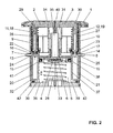
- the piston 6 is shown in the starting position and in the Figures 3 and 4 the piston 6 is in the end position.
- each of the actuating elements 2, 3 comprises a closure element 9, 10 Closing element 9, 10 closes tightly on actuation of the actuating elements 2, 3 of one of the two fluid outlets 7, 8 for the fluid, whereby the fluid can not flow out through the sealed fluid outlet 7, 8.
- the fluid will inevitably have to flow out through the other fluid outlet. This will be in the Figures 3 and 4 well shown. This allows the Zweimengen Erasmusung be achieved.
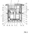
- the user has actuated the actuator 2.
- the actuating element 2 is shown here in its end position.
- the fluid F which was located in the piston chamber 5 before actuation, flowed over the other fluid outlet 8 along the dashed line F.
- only one of the fluid outputs 7, 8 is acted upon by the actuation of one of the actuators with a pressure pulse, whereby only those elements are controlled at the drain valve, which are provided for the corresponding flush.
- the arrangement of the closure element 11, 12 has the advantage that only a single cylinder 4 is provided for the provision of the pressure pulse. Consequently, the space of such an actuator 1 can be chosen substantially smaller than in devices with telescopic cylinders or double-arranged cylinders. In addition, the reliability is increased because it is always ensured by the closure of the corresponding fluid outlet 7, 8, that the fluid must flow through the other fluid outlet.
- FIG. 2 can be well recognized that the closure elements 9, 10 with respect to the actuating direction of the actuating elements 2, 3 and the piston 6 are arranged laterally to the piston chamber 5.
- the lateral arrangement of the installation space can be further reduced, which further increases the compactness of the actuator 1.
- Each of the actuating elements 2, 3 preferably comprises a closure element 9, 10 in the form of a plunger 11, 12 which is in communication with the actuating element 2, 3.
- the plunger 11, 12 can be molded onto the actuating element 2, 3.
- the actuating element 2 is followed by a plunger 11 and the actuating element 3, a plunger 12 at.
- the plungers have both the function of closing off the fluid outlets 7, 8 and also a guiding function of the actuating element 2, 3.
- the plunger 11, 12 is moved from a starting position into an end position.
- the plunger 11 is mounted here in a cylindrical opening 20, 21 and is moved in this opening 20, 21. In these cylindrical openings 20, 21, the fluid outlet 7, 8 opens.
- the openings 20, 21 fluidly connected to the piston chamber 5 in connection.
- the fluid located in the piston chamber 5 moves through the cylindrical opening 20, 21 to the corresponding fluid outlet 7, 8.
- the plunger 11 is moved in front of the fluid outlet 7, 8 and closes it off accordingly.
- the fluid outlet 7, 8 is preferably arranged in the first third, more preferably in the first quarter or in the first fifth, of said path, so that the fluid outlet is closed shortly after the actuation has been triggered. This ensures that only one of the fluid outputs 7, 8 is acted upon by the pressure pulse intended for triggering the flushing.
- the fluid outlet 7, 8 comprises an opening 13, 14 in a housing wall 15 of the actuating device 1.
- the closure element 9, 10 is preferably located directly on the edge 16, 17 of the opening 13, 14.
- the fluid outlet is formed here nozzle-shaped, so that the control line is easy to connect.
- the openings 13, 14 extend while passing through the neck.
- the closure element 9, 10 has the shape of a control cylinder 18, 19 with a control piston chamber 20, 21 and a control piston 22, 23.
- the said fluid outlet 7, 8 opens into the control piston chamber 20, 21.
- the control piston chamber 20, 21 is then in turn connected to the piston chamber 5.
- the fluid flows from the piston chamber 5 into the control piston chamber 21 and finally through the fluid outlet 8 to the drain valve.
- the fluid outlet 7 is closed by the control piston 22.
- the fluid flows from the piston chamber 5 into the control piston chamber 20 and then to the fluid outlet 7.
- the fluid outlet 8 is closed by the control piston 23 accordingly. This can turn into the Figures 3 and 4 be recognized very well.
- the two control pistons 22, 23 release the mouth of the fluid outlet 7, 8 in the control piston chamber 20, 21 accordingly.
- the respective control piston 22 or 23 is guided via the mouth of the fluid outlet 7, 8 in the control piston chamber 20 or 21, so that the control piston 22, 23 closes the corresponding fluid outlet 7 or 8 accordingly.
- the control piston 22, 23 have at their lower end a seal 24, 25 which seal the control piston 22, 23 to the respective control piston chamber 20, 21.
- the fluid outlet 7, 8 will be closed by this seal 24, 25 accordingly.
- the seal 24, 25 substantially seals the annular gap between the control piston 22, 23 and the control piston chamber 20, 21. This seal prevents air from flowing through the seal. In other words, it can also be said that as soon as the seal 24, 25 has passed the mouth of the fluid outlet 7 or 8 into the control piston chamber 20 or 21, the corresponding fluid outlet 7 or 8 is closed.
- control piston chamber 20, 21 must have a diameter matching the lateral surface 26, 27 so that there is no or only a very small annular gap between the control piston chamber and the lateral surface.
- the piston 6 can be brought with a return element 28, here in the form of a pressure spring arranged in the piston chamber 5 from the end position to the starting position.
- the compression spring thus pushes the piston 6 after actuation of the bottom 36 of the piston chamber back to the starting position.
- the restoring element 28 is correspondingly subjected to a force and compressed against the restoring force.
- the return element 28 can also also serve as a return element for the two actuators 2, 3.
- an additional return element 29, 30 can also be arranged per actuating element 2, 3.
- a corresponding compression spring 29, 30 is shown, wherein the compression spring extends around the plunger 11, 12 and the control piston 22, 23 around here.
- This compression spring 29, 30 returns the actuator 2, 3 after the operation of the end position in the starting position and holds the actuator 2, 3 in the corresponding starting position.
- each actuating element 2, 3 each arranged a return element.
- the arrangement of the additional return elements 29, 30 has the advantage that the return of the operating buttons 2, 3 can be done with a greater speed than the provision of the piston 6. This is more ergonomic for the user, because the fast reset, the user better recognize the triggering of the flushing.
- the piston 6 also has an actuating surface 31.
- the actuating surface 31 is part of a piston rod 34, which adjoins the piston 6.
- the actuating movement of the actuating elements 2, 3 is transmitted to the piston 6 and the piston rod 34.
- the actuators 2, 3 are therefore in contact with the actuating surface 31 in contact.
- the actuating elements 2, 3 act on the single piston 6.
- the actuating elements 2, 3 can also be in contact with the actuating surface 31 during the return.
- the piston is mounted to the housing, wherein the housing has a corresponding bearing opening 41.
- the storage opening 41 is arranged in the wall 42 of the piston chamber.
- the wall 42 also separates the piston chamber 5 to the actuators 2, 3 from.
- the side wall 37 of the piston chamber 5 has in the lower region, ie in the region of the bottom 36, a first and second passage 39, which connects the piston chamber 5 with the openings 20, 21.
- the fluid can thus enter from the piston chamber 5 into the respective opening 20, 21 or control piston chamber 20, 21 via these passages 39.
- the passage 39 may also be designed differently.
- the passages 39 are preferably arranged in the region of the end position of the piston 6, that is to say in the region of the cylinder bottom 36.
- the fluid outlets 7, 8 are arranged at a distance from the cylinder bottom 36.
- the actuating device 1 preferably comprises a housing 32, wherein the housing 32 at least the piston chamber 5 provides so both fluid outlets 7, 8 are arranged laterally to the piston chamber 5.
- the openings 20, 21 are also arranged laterally to the piston chamber.
- a valve 33 is arranged in the piston 6, .
- the valve may be, for example, a diaphragm valve or a small-diameter opening.
- the valve 33 opens during the movement of the piston 6 from the end position to the starting position, so that ambient air or a replacement fluid can flow into the piston chamber 5 through the piston 6.
- the valve 33 is arranged below the piston rod 34, wherein the piston rod 34 is provided with a central opening 35.
- the central opening 35 can be provided by a gap 40 between the two actuators 2, 3 with ambient air.
- the actuators 2, 3 can be said that they are supported by the plunger 11, 12 and the control piston 22, 23 in the opening 20, 21.
- the actuating element of the housing wall 15 are surrounded.
- the cylinder bottom 36 is fixed to the housing wall 15 with a sealing element 42 in connection. However, the cylinder bottom 36 can be removed to the housing wall 15, which allows easy installation.
- the present actuating device 1 can be made extremely compact with the one piston 6 responsible for the actuation.
- a particularly compact actuating device 1 with respect to a view perpendicular to the actuating buttons 2, 3 are provided.
- the installation depth along the actuation axis and the diameter is comparatively compact, which has a further advantage.
Landscapes
- Engineering & Computer Science (AREA)
- Health & Medical Sciences (AREA)
- Life Sciences & Earth Sciences (AREA)
- Hydrology & Water Resources (AREA)
- Public Health (AREA)
- Water Supply & Treatment (AREA)
- Mechanical Engineering (AREA)
- Aviation & Aerospace Engineering (AREA)
- Fluid-Driven Valves (AREA)
Abstract
Description
- Die vorliegende Erfindung betrifft eine Vorrichtung zur fluidischen Betätigung eines Ablaufventils nach dem Oberbegriff von Anspruch 1.
- Aus dem Stand der Technik sind fluidisch betätigbare Vorrichtungen zur Betätigung eines Ablaufventils bekannt.
- Beispielsweise zeigt die
EP 1 719 846 eine derartige pneumatisch betätigbare Betätigungsvorrichtung. Diese Betätigungsvorrichtung umfasst ein mit einem Ablaufventil über eine Rohrleitung in Verbindung stehendes Betätigungselement. Das Betätigungselement umfasst einen Faltenbalg, welcher durch zwei Tasten betätigbar ist. Die Taste komprimieren dabei den Faltenbalg unterschiedlich, so dass bei der Betätigung mit einer Taste ein grösseres Luftvolumen aus dem Faltenbalg entnehmbar ist, als mit der Betätigung der anderen Taste. Hierdurch kann eine Zweimengenspülung erreicht werden. Nachteilig an derEP 1 719 846 ist die Anordnung des Faltenbalges, weil dessen Lebensdauer nicht die gewünschte Anzahl von Betätigungen zulässt. Zudem ist der Montageaufwand erheblich und fehleranfällig. - Aus der
EP 1 498 553 ist eine Zweimengen-Betätigungsvorrichtung bekannt, welche zwei ineinander geschachtelte Zylinder für die Vollmengenbetätigung und die Zweimengenbetätigung aufweist. Die Vorrichtung hat aber den Nachteil, dass die Baugrösse, insbesondere die Einbautiefe relativ gross ist. - Nachteilig an der technischen Lehre von
EP 1 719 846 undEP 1 498 553 ist die Tatsache, dass das Ablaufventil über das Luftvolumen gesteuert wird, was nur eine unpräzise Ansteuerung des Ablaufventils erlaubt. - Aus der
CN 201214818 ist weiter eine Betätigungsvorrichtung bekannt, welche zwei verschiedene Steuerleitungen mit einem Druckpuls beaufschlagt. Der Luftaustritt aus der Betätigungsvorrichtung wird über einen quer liegenden Stössel gesteuert, welcher bei Betätigung der einen Taste gegen die Rückstellkraft einer Feder betätigt wird und bei Betätigung der anderen Taste in der Ausgangsstellung verharrt. Der Stössel blockiert dabei immer eine der beiden Steuerleitungen. Nachteilig an derCN 201214818 ist die Anordnung des Stössels, welcher den Aufbau technisch aufwendig macht. Zudem muss die Bewegung der Taste auf den Stössel umgelenkt werden, was der Betriebssicherheit abträglich ist. - Ausgehend von diesem Stand der Technik liegt der Erfindung die Aufgabe zugrunde, eine Zweimengen-Betätigungsvorrichtung anzugeben, welche die Nachteile des Standes der Technik überwindet. Insbesondere soll eine besonders zuverlässig funktionierende und kompakte Betätigungsvorrichtung angegeben werden.
- Diese Aufgabe löst der Gegenstand nach Anspruch 1. Demgemäss umfasst eine fluidische Betätigungsvorrichtung für die Betätigung eines Ablaufventils in einem Spülkasten ein erstes Betätigungselement für die Auslösung einer Teilmengenspülung, ein zweites Betätigungselement für die Auslösung einer Vollmengenspülung, wobei die Betätigungselemente zur Betätigung des Ablaufventils von einer Ausgangslage in eine Endlage bewegbar sind, einen Zylinder mit einem Kolbenraum und einem im Kolbenraum bewegbaren Kolben, und zwei verschiedene mit dem Kolbenraum fluidisch in Verbindung stehende Fluidausgänge, an welche je eine Steuerleitung des Ablaufventils anschliessbar ist. Durch die Bewegung des Kolbens ist ein im Kolbenraum vorhandenes Fluid zu den und durch die Fluidausgänge bewegbar. Die beiden Betätigungselemente wirken auf den einen Kolben und bewegen diesen bei Betätigung im Kolbenraum von einer Ausgangslage in eine Endlage. Jedes der Betätigungselemente umfasst ein Verschlusselement, welches bei Betätigung einer der beiden Fluidausgänge für das Fluid dicht verschliesst, so dass das Fluid aus dem Kolbenraum zwangsweise durch den anderen Fluidausgang ausströmt.
- Durch die Anordnung des Verschlusselementes wird der fragliche Verschlussausgang bei Betätigung des jeweiligen Betätigungselementes sicher verschlossen, während der andere Fluidausgang immer offen bleibt, wodurch Fehlbetätigungen nahezu ausgeschlossen werden können. Weiter kann aufgrund der Anordnung eines einzigen Zylinders die Baugrösse, insbesondere die Tiefe in Richtung der Betätigung gesehen oder der Durchmesser, verkleinert werden.
- Vorzugsweise sind die Verschlusselemente bezüglich der Betätigungsrichtung der Betätigungselemente bzw. des Kolbens seitlich zum Kolbenraum angeordnet. Hierdurch kann der Durchmesser noch weiter verkleinert werden.
- In einer Weiterbildung der Erfindung umfasst jedes der Betätigungselemente ein Verschlusselement in der Gestalt eines mit dem Betätigungselement in Verbindung stehenden Stössels. Der Stössel ist dann bei Betätigung vor den Fluidausgang bewegbar. In der Ausgangslage ist der Fluidausgang stösselfrei, also nicht durch den Stössel verdeckt. Beim Stössel handelt es sich um eine sehr einfache Ausführungsform.
- Vorzugsweise wird das Verschlusselement von einer Ausgangslage entlang der gleichen Richtung wie das jeweilige Betätigungselement in eine Endlage bewegt. Es erfolgt keine Umlenkung der Bewegung, was bezüglich der Betriebssicherheit vorteilhaft ist.
- Bevorzugt legt das Verschlusselement von seiner Ausgangslage in die Endlage eine definierte Wegstrecke zurück, wobei der Fluidausgang im ersten Drittel, insbesondere im ersten Viertel, besonders bevorzugt im ersten Fünftel, dieser besagten Wegstrecke angeordnet ist. Somit wird der Fluidausgang kurz nach Auslösen der Betätigung verschlossen.
- Vorzugsweise umfasst jeder der Fluidausgänge eine Öffnung in einer Gehäusewand, wobei das Verschlusselement in der Ausgangslage in der Nähe des Randes der Öffnung, vorzugsweise unmittelbar am Rand der Öffnung, positioniert ist und bei Betätigung über die Öffnung geführt wird, wobei die Öffnung dann bezüglich des Kolbenraums verschlossen wird.
- In einer Weiterbildung der Erfindung weist das Verschlusselement die Gestalt eines Steuerzylinders mit einem Steuerkolbenraum und einem Steuerkolben auf, wobei der Steuerkolbenraum in den besagten Fluidausgang übergeht, und wobei der Kolbenraum mit dem Steuerkolbenraum fluidisch verbunden ist. Der Steuerkolben gibt in der Ausgangslage den Fluidausgang frei und wird bei Betätigung über den Fluidausgang geführt, so dass der Steuerkolben den Fluidausgang verschliesst. Der Stössel weist dabei die Gestalt des Steuerkolbens auf.
- Vorzugsweise sind die beiden Steuerkolbenräume seitlich zum Kolbenraum angeordnet. Der Fluidausgang liegt vorzugsweise rechtwinklig zum entsprechenden Steuerkolbenraum.
- Vorzugsweise ist der Steuerkolben mit einer Dichtung zum Steuerkolbenraum gedichtet, wobei der Fluidausgang über diese Dichtung verschliessbar ist. Alternativ weist der Steuerkolben eine Mantelfläche auf, welche bei Betätigung vor den Fluidausgang zu liegen kommt und diesen verschliesst.
- Vorzugsweise ist der Kolben mit einem Rückstellelement, insbesondere einer Druckfeder, nach erfolgter Betätigung von der Endlage in die Ausgangslage bringbar.
- Zusätzlich zum Rückstellelement des Kolbens ist vorzugsweise ein Rückstellelement, insbesondere eine Druckfeder, für die Betätigungselemente angeordnet, mit welchem nach erfolgter Betätigung das Betätigungselement von der Endlage in die Ausgangslage bringbar ist, wobei pro Betätigungselement vorzugsweise ein Rückstellelement angeordnet ist.
- Vorzugsweise weist der Kolben eine Betätigungsfläche auf und die Betätigungselemente sind bei Betätigung und/oder Rückstellung mit der Betätigungsfläche in Kontakt.
- Vorzugsweise umfasst die Betätigungsvorrichtung ein Gehäuse, wobei das Gehäuse mindestens den Kolbenraum und ggf. den Steuerkolbenraum bereitstellt und wobei die Fluidausgänge winklig, vorzugsweise rechtwinklig, zum Kolbenraum bzw. zum Steuerkolbenraum angeordnet sind. Gegebenenfalls sind auch die Steuerzylinder seitlich zum Kolbenraum angeordnet.
- Vorzugsweise ist der Kolbenraum über jeweils einen Durchgang mit den Fluidausgängen fluidisch verbunden, wobei das Fluid über diesen Durchgang zu den Fluidausgängen strömt. Pro Fluidausgang ist ein Durchgang angeordnet. Gegebenenfalls stellt der Durchgang die fluidische Verbindung zwischen Kolbenraum und Steuerkolbenraum, der zum Fluidausgang führt, bereit.
- Weitere Ausführungsformen sind in den abhängigen Ansprüchen angegeben.
- Bevorzugte Ausführungsformen der Erfindung werden im Folgenden anhand der Zeichnungen beschrieben, die lediglich zur Erläuterung dienen und nicht einschränkend auszulegen sind. In den Zeichnungen zeigen:
- Fig. 1
- eine perspektivische Ansicht einer fluidischen Betätigungsvorrichtung nach einer Ausführungsform;
- Fig. 2
- eine Schnittdarstellung der Betätigungsvorrichtung nach
Figur 1 in der Ausgangslage; - Fig. 3
- eine Schnittdarstellung der Betätigungsvorrichtung nach
Figur 1 mit betätigtem ersten Betätigungselement; und - Fig. 4
- eine Schnittdarstellung der Betätigungsvorrichtung nach
Figur 1 mit betätigtem zweiten Betätigungselement. - In der
Figur 1 wird eine Ausführungsform einer fluidischen Betätigungsvorrichtung 1 für die Betätigung eines Ablaufventils in einem Spülkasten gezeigt. Mit der Betätigungsvorrichtung 1 kann ein Fluid in Bewegung gesetzt werden, wobei das Fluid dann als Steuergrösse auf ein mit dem Fluid betätigbares Ablaufventil bewirkt. Das Ablaufventil wird also durch einen Fluidimpuls angehoben, wodurch ein Spülvorgang eingeleitet wird. Unter einem Fluid wird hier vorzugsweise Umgebungsluft verstanden. Die Ausdrucksweise Fluid schliesst aber auch andere gasförmige Stoffe oder flüssige Stoffe mit ein. - Die Betätigungsvorrichtung 1 umfasst ein erstes Betätigungselement 2 für die Auslösung einer Teilmengenspülung und ein zweites Betätigungselement 3 für die Auslösung einer Vollmengenspülung. Es handelt sich also um eine Zweimengen-Betätigungsvorrichtung 1. Die beiden Betätigungselemente 2, 3 sind zur Betätigung des Ablaufventils von einer Ausganslage in eine Endlage bewegbar. Nach erfolgter Betätigung werden die Betätigungselemente 2, 3 von der Endlage wiederum in die Ausgangslage zurückgestellt. Bei der Betätigung wird ein entsprechender Druckpuls durch das Fluid auf das Ablaufventil übertragen.
- Von der Schnittdarstellung der
Figur 2 kann weiter erkannt werden, dass die Betätigungsvorrichtung 1 zudem einen Zylinder 4 mit einem Kolbenraum 5 und einem im Kolbenraum 5 bewegbaren Kolben 6 umfasst. Zudem umfasst die Betätigungsvorrichtung 1 zwei verschiedene Fluidausgänge 7, 8. An diese Fluidausgänge 7, 8 ist je eine Steuerleitung des Ablaufventils anschliessbar. Folglich steht die Betätigungsvorrichtung über zwei nicht dargestellte Steuerleitungen mit einem entsprechend ausgebildeten Ablaufventil in Verbindung. Bei einer Bewegung des Kolbens 6 wird ein im Kolbenraum 5 vorhandenes Fluid durch einen der beiden Fluidausgänge 7, 8 bewegt. Von den Fluidausgängen wird das Fluid dann über die Steuerleitungen zum Ablaufventil gebracht, welches durch das Fluid betätigbar ist. Das Ablaufventil wird angehoben und über Elemente des Ablaufventils, wie beispielsweise Schwimmer, offen gehalten, bis die vorbestimmte Menge Spülwasser aus dem Spülkasten entnommen wurde. - Die beiden Betätigungselemente 2, 3 wirken auf den einen einzigen Kolben 6. Der Kolben 6 wird bei Betätigung im Kolbenraum von einer Ausgangslange in eine Endlage bewegt. In der
Figur 2 wird der Kolben 6 in der Ausgangslage gezeigt und in denFiguren 3 und4 liegt der Kolben 6 in der Endlage. - Weiter umfasst jedes der Betätigungselemente 2, 3 ein Verschlusselement 9, 10. Das Verschlusselement 9, 10 schliesst bei Betätigung der Betätigungselemente 2, 3 einer der beiden Fluidausgänge 7, 8 für das Fluid dicht ab, wodurch das Fluid nicht durch den abgedichteten Fluidausgang 7, 8 ausströmen kann. So wird das Fluid zwangsweise durch den anderen Fluidausgang ausströmen müssen. Dies wird in den
Figuren 3 und4 gut gezeigt. Hierdurch kann die Zweimengenspülung erreicht werden. - In der
Figur 3 hat der Benutzer das Betätigungselement 2 betätigt. Das Betätigungselement 2 wird hier in seiner Endlage gezeigt. Bei Betätigung wird dabei der Fluidausgang 7 durch das Verschlusselement 11 bezüglich des Fluides F dicht verschlossen. Das Fluid F, welches sich im Kolbenraum 5 vor der Betätigung befand, strömte über den anderen Fluidausgang 8 entlang der gestrichelten Linie F hinaus. Somit wird also nur einer der Fluidausgänge 7, 8 bei der Betätigung eines der Betätigungselemente mit einem Druckpuls beaufschlagt, wodurch nur diejenigen Elemente am Ablaufventil angesteuert werden, welche für die entsprechende Spülung vorgesehen sind. - In der
Figur 4 hat der Benutzer das andere Betätigungselement 3 betätigt. Hierbei wird der Fluidausgang 8 durch das Verschlusselement 12 bezüglich des Fluides F dicht verschlossen. Das Fluid aus dem Kolbenraum 5 wird daher durch den Fluidausgang 7 ausströmen. - Die Anordnung des Verschlusselementes 11, 12 hat den Vorteil, dass nur ein einziger Zylinder 4 für die Bereitstellung des Druckimpulses vorzusehen ist. Folglich kann der Bauraum einer solchen Betätigungsvorrichtung 1 wesentlich kleiner gewählt werden, als bei Vorrichtungen mit Teleskopzylindern oder doppelt angeordneten Zylindern. Zudem wird auch die Betriebssicherheit erhöht, weil durch den Verschluss des entsprechenden Fluidausganges 7, 8 immer sichergestellt wird, dass das Fluid durch den anderen Fluidausgang ausströmen muss.
- Von der
Figur 2 kann gut erkannt werden, dass die Verschlusselemente 9, 10 bezüglich der Betätigungsrichtung der Betätigungselemente 2, 3 bzw. des Kolbens 6 seitlich zum Kolbenraum 5 angeordnet sind. Durch die seitliche Anordnung kann der Einbauraum weiter verringert werden, was die Kompaktheit der Betätigungsvorrichtung 1 weiter erhöht. - Jedes der Betätigungselemente 2, 3 umfasst vorzugsweise ein Verschlusselement 9, 10 in der Gestalt eines mit dem Betätigungselement 2, 3 in Verbindung stehenden Stössels 11, 12. Der Stössel 11, 12 kann dabei dem Betätigungselement 2, 3 angeformt sein. Dem Betätigungselement 2 schliesst sich ein Stössel 11 und dem Betätigungselement 3 ein Stössel 12 an. Die Stössel haben sowohl die Funktion des Abschliessens der Fluidausgänge 7, 8 als auch eine Führungsfunktion des Betätigungselementes 2, 3. Bei der Betätigung wird der Stössel 11, 12 von einer Ausgangslage in eine Endlage bewegt. Der Stössel 11 ist hier in einer zylindrischen Öffnung 20, 21 gelagert und wird in dieser Öffnung 20, 21 bewegt. In diese zylindrischen Öffnungen 20, 21 mündet der Fluidausgang 7, 8. Weiter stehen die Öffnungen 20, 21 fluidisch mit dem Kolbenraum 5 in Verbindung. Mit anderen Worten kann gesagt werden, dass das sich im Kolbenraum 5 befindliche Fluid durch die zylindrische Öffnung 20, 21 zu dem entsprechenden Fluidausgang 7, 8 bewegt. Bei der Betätigung wird der Stössel 11 vor dem Fluidausgang 7, 8 bewegt und schliesst diesen entsprechend ab.
- Bei der Bewegung des Verschlusselementes 9, 10 von seiner Ausgangslage in seine Endlage legt das Verschlusselement 9, 10 eine definierte Wegstrecke zurück. Der Fluidausgang 7, 8 ist vorzugsweise im ersten Drittel, besonders bevorzugt im ersten Viertel oder im ersten Fünftel, dieser besagten Wegstrecke angeordnet, so dass der Fluidausgang kurz nach Auslösen der Betätigung verschlossen wird. Somit wird sichergestellt, dass nur einer der Fluidausgänge 7, 8 mit dem für die Auslösung der Spülung vorgesehenen Druckimpuls beaufschlagt wird.
- Der Fluidausgang 7, 8 umfasst in der vorliegend gezeigten Ausführungsform eine Öffnung 13, 14 in einer Gehäusewand 15 der Betätigungsvorrichtung 1. In der Ausgangslage steht das Verschlusselement 9, 10 vorzugsweise unmittelbar am Rand 16, 17 der Öffnung 13, 14. Durch diese relative Positionierung kann erreicht werden, dass der abzuschliessende Fluidausgang 7, 8 unmittelbar nach Betätigung des Betätigungselementes 2, 3 abgeschlossen wird, was die Betriebssicherheit weiter erhöht.
- Ausserhalb der Gehäusewand 15 ist der Fluidausgang hier stutzenförmig ausgebildet, so dass die Steuerleitung einfach anschliessbar ist. Die Öffnungen 13, 14 erstrecken sich dabei durch den Stutzen hindurch.
- Mit anderen Worten bezüglich einer besonders bevorzugten Ausführungsform kann auch gesagt werden, dass das Verschlusselement 9, 10 die Gestalt eines Steuerzylinders 18, 19 mit einem Steuerkolbenraum 20, 21 und einem Steuerkolben 22, 23 aufweist. Der besagte Fluidausgang 7, 8 mündet dabei in den Steuerkolbenraum 20, 21. Der Steuerkolbenraum 20, 21 ist dann seinerseits mit dem Kolbenraum 5 verbunden. Bei einer Betätigung des Betätigungselementes 2 strömt das Fluid aus dem Kolbenraum 5 in den Steuerkolbenraum 21 und schliesslich durch den Fluidausgang 8 zum Ablaufventil. Der Fluidausgang 7 wird dabei durch den Steuerkolben 22 verschlossen. Bei einer Betätigung des Betätigungselementes 3 fliesst das Fluid aus dem Kolbenraum 5 in den Steuerkolbenraum 20 und dann zum Fluidausgang 7. Der Fluidausgang 8 wird dabei durch den Steuerkolben 23 entsprechend verschlossen. Dies kann wiederum in den
Figuren 3 und4 besonders gut erkannt werden. - In der Ausgangslage geben die beiden Steuerkolben 22, 23 die Mündung des Fluidausganges 7, 8 in den Steuerkolbenraum 20, 21 entsprechend frei. Bei einer Betätigung wird der jeweilige Steuerkolben 22 oder 23 über die Mündung des Fluidausganges 7, 8 in den Steuerkolbenraum 20 oder 21 geführt, so dass der Steuerkolben 22, 23 den entsprechenden Fluidausgang 7 oder 8 entsprechend verschliesst.
- Die Steuerkolben 22, 23 weisen an ihrem unteren Ende eine Dichtung 24, 25 auf, welche den Steuerkolben 22, 23 zum jeweiligen Steuerkolbenraum 20, 21 abdichten. Der Fluidausgang 7, 8 wird dabei über diese Dichtung 24, 25 entsprechend verschlossen werden. Die Dichtung 24, 25 dichtet im Wesentlichen den Ringspalt zwischen dem Steuerkolben 22, 23 und dem Steuerkolbenraum 20, 21 ab. Durch diese Abdichtung vermag keine Luft durch die Dichtung strömen. Mit anderen Worten kann auch gesagt werden, dass sobald die Dichtung 24, 25 die Mündung des Fluidausganges 7 oder 8 in den Steuerkolbenraum 20 oder 21 passiert hat, der entsprechende Fluidausgang 7 oder 8 verschlossen wird.
- Alternativ kann auch auf die Dichtung 24, 25 verzichtet werden, wenn der Steuerkolben eine Mantelfläche 26, 27 aufweist, mit welcher dann der Fluidausgang 7, 8 in analoger Weise verschlossen werden kann. Hierfür muss der Steuerkolbenraum 20, 21 aber einen zur Mantelfläche 26, 27 passenden Durchmesser aufweisen, so dass zwischen dem Steuerkolbenraum und der Mantelfläche keinen oder nur ein sehr geringer Ringspalt vorhanden ist.
- Der Kolben 6 ist mit einem Rückstellelement 28, hier in der Gestalt einer im Kolbenraum 5 angeordneten Druckfeder von der Endlage in die Ausgangslage bringbar. Die Druckfeder drückt somit den Kolben 6 nach erfolgter Betätigung vom Boden 36 des Kolbenraums wieder zurück in die Ausgangslage. Weiter hält die Druckfeder 28 den Kolben 6 in der Ausgangslage. Sobald eine der beiden Betätigungselemente 2, 3 betätigt wird, wird das Rückstellelement 28 entsprechend mit einer Kraft beaufschlagt und gegen die Rückstellkraft komprimiert.
- Das Rückstellelement 28 kann zudem auch gleich als Rückstellelement für die beiden Betätigungselemente 2, 3 dienen.
- Weiter kann pro Betätigungselement 2, 3 auch noch ein zusätzliches Rückstellelement 29, 30 angeordnet werden. In den Figuren wird wiederum eine entsprechende Druckfeder 29, 30 gezeigt, wobei sich die Druckfeder hier um den Stössel 11, 12 bzw. den Steuerkolben 22, 23 herum erstreckt. Diese Druckfeder 29, 30 stellt das Betätigungselement 2, 3 nach erfolgter Betätigung von der Endlage in die Ausgangslage zurück und hält das Betätigungselement 2, 3 in der entsprechenden Ausgangslage. Vorzugsweise ist dabei pro Betätigungselement 2, 3 je ein Rückstellelement angeordnet. Die Anordnung der zusätzlichen Rückstellelemente 29, 30 hat den Vorteil, dass die Rückstellung der Betätigungstasten 2, 3 mit einer grösseren Geschwindigkeit erfolgen kann, als die Rückstellung des Kolbens 6. Dies ist für den Benutzer ergonomischer, denn durch die schnelle Rückstellung kann der Benutzer besser die Auslösung der Spülung erkennen.
- Der Kolben 6 weist weiterhin eine Betätigungsfläche 31 auf. In der vorliegenden Ausführungsform ist die Betätigungsfläche 31 Teil einer Kolbenstange 34, die sich dem Kolben 6 anschliesst. Über diese Betätigungsfläche 31 wird die Betätigungsbewegung der Betätigungselemente 2, 3 auf den Kolben 6 bzw. die Kolbenstange 34 übertragen. Die Betätigungselemente 2, 3 sind also bei Betätigung mit der Betätigungsfläche 31 in Kontakt.
- Die Betätigungselemente 2,3 wirken dabei auf den einzigen Kolben 6. Auch können die Betätigungselemente 2,3 bei der Rückstellung mit der Betätigungsfläche 31 in Kontakt sein.
- Über die Kolbenstange 34 wird der Kolben zum Gehäuse gelagert, wobei das Gehäuse eine entsprechende Lageröffnung 41 aufweist. Die Lagerungsöffnung 41 ist dabei in der Wand 42 des Kolbenraumes angeordnet. Die Wand 42 trennt zudem den Kolbenraum 5 zu den Betätigungselementen 2, 3 ab.
- Bezüglich der Seitenwand 37 des Kolbenraums 5 ist der Kolben 6 mit einer Dichtung 38 abgedichtet. Die Seitenwand 37 weist im unteren Bereich, also im Bereich des Bodens 36 einen ersten und zweiten Durchgang 39 auf, welche den Kolbenraum 5 mit den Öffnungen 20, 21 verbindet. Über diese Durchgänge 39 kann das Fluid also vom Kolbenraum 5 in die jeweilige Öffnung 20, 21 bzw. Steuerkolbenraum 20, 21 eintreten. Der Durchgang 39 kann aber auch anders ausgebildet sein.
- Die Durchgänge 39 sind vorzugsweise im Bereich der Endlage des Kolbens 6, also im Bereich des Zylinderbodens 36 angeordnet. Die Fluidausgänge 7, 8 sind beabstandet zum Zylinderboden 36 angeordnet.
- Die Betätigungsvorrichtung 1 umfasst vorzugsweise ein Gehäuse 32, wobei das Gehäuse 32 mindestens den Kolbenraum 5 bereitstellt umso beide Fluidausgänge 7, 8 seitlich zum Kolbenraum 5 angeordnet sind. In der vorliegenden Ausführungsform sind ebenfalls die Öffnungen 20, 21 seitlich zum Kolbenraum angeordnet.
- Im Kolben 6 ist ein Ventil 33 angeordnet. Das Ventil kann beispielsweise ein Membranventil oder aber eine mit einem geringen Durchmesser ausgebildete Öffnung sein. Das Ventil 33 öffnet sich bei der Bewegung des Kolbens 6 von der Endlage in die Ausgangslage, so dass durch den Kolben 6 Umgebungsluft oder ein Ersatzfluid in den Kolbenraum 5 strömen kann. In der vorliegenden Ausführungsform ist das Ventil 33 unterhalb der Kolbenstange 34 angeordnet, wobei die Kolbenstange 34 mit einer zentralen Öffnung 35 versehen ist. Die zentrale Öffnung 35 kann dabei durch einen Spalt 40 zwischen den beiden Betätigungselementen 2, 3 mit Umgebungsluft versehen werden. Bezüglich den Betätigungselementen 2, 3 kann gesagt werden, dass diese durch die Stössel 11, 12 bzw. die Steuerkolben 22, 23 in der Öffnung 20, 21 gelagert sind. Zudem sind die Betätigungselement von der Gehäusewand 15 umgeben.
- Der Zylinderboden 36 steht hier mit der Gehäusewand 15 mit einem Dichtungselement 42 fest in Verbindung. Der Zylinderboden 36 kann aber zur Gehäusewand 15 entfernt werden, was eine einfache Montage erlaubt.
- Zusammenfassend kann gesagt werden, dass die vorliegende Betätigungsvorrichtung 1 mit dem einen für die Betätigung verantwortlichen Kolben 6 äusserst kompakt ausgebildet werden kann. Hierdurch kann zudem eine besonders kompakte Betätigungsvorrichtung 1 bezüglich einer Ansicht senkrecht auf die Betätigungstasten 2, 3 bereitgestellt werden. Weiter ist auch die Einbautiefe entlang der Betätigungsachse und der Durchmesser vergleichsweise kompakt, was einen weiteren Vorteil aufweist.
-
- 1
- Betätigungsvorrichtung
- 2
- erstes Betätigungselement
- 3
- zweites Betätigungselement
- 4
- Zylinder
- 5
- Kolbenraum
- 6
- Kolben
- 7
- Fluidausgang
- 8
- Fluidausgang
- 9
- Verschlusselement
- 10
- Verschlusselement
- 11
- Stössel
- 12
- Stössel
- 13
- Öffnung
- 14
- Öffnung
- 15
- Gehäusewand
- 16
- Rand
- 17
- Rand
- 18
- Steuerzylinder
- 19
- Steuerzylinder
- 20
- zylindrische Öffnung, Steuerkolbenraum
- 21
- zylindrische Öffnung, Steuerkolbenraum
- 22
- Steuerkolben
- 23
- Steuerkolben
- 24
- Dichtung
- 25
- Dichtung
- 26
- Mantelfläche
- 27
- Mantelfläche
- 28
- Rückstellelement
- 29
- Rückstellelement
- 30
- Rückstellelement
- 31
- Betätigungsfläche
- 32
- Gehäuse
- 33
- Ventil
- 34
- Kolbenstange
- 35
- Öffnung
- 36
- Boden
- 37
- Seitenwand
- 38
- Dichtung
- 39
- Durchgang
- 40
- Spalt
- 41
- Lagerungsöffnung
- 42
- Dichtungselement
Claims (15)
- Fluidische Betätigungsvorrichtung (1) für die Betätigung eines Ablaufventils in einem Spülkasten umfassend
ein erstes Betätigungselement (2) für die Auslösung einer Teilmengenspülung,
ein zweites Betätigungselement (3) für die Auslösung einer Vollmengenspülung, wobei die Betätigungselemente (2, 3) zur Betätigung des Ablaufventils von einer Ausgangslage in eine Endlage bewegbar sind,
einen Zylinder (4) mit einem Kolbenraum (5) und einem im Kolbenraum (5) bewegbaren Kolben (6), und
zwei verschiedene mit dem Kolbenraum (6) fluidisch in Verbindung stehende Fluidausgänge (7, 8), an welche je eine Steuerleitung des Ablaufventils anschliessbar ist, wobei durch die Bewegung des Kolbens (6) ein im Kolbenraum (5) vorhandenes Fluid (F) zu den und durch die Fluidausgänge (7, 8) bewegbar ist,
dadurch gekennzeichnet, dass die beiden Betätigungselemente (2, 3) auf den einen Kolben (6) wirken und diesen bei Betätigung im Kolbenraum (5) von einer Ausgangslage in eine Endlage bewegen und dass jedes der Betätigungselemente (2, 3) ein Verschlusselement (9, 10) umfasst, welches bei Betätigung einer der beiden Fluidausgänge (7, 8) für das Fluid (F) dicht verschliesst, so dass das Fluid (F) aus dem Kolbenraum (5) zwangsweise durch den anderen Fluidausgang (8, 7) ausströmt. - Fluidische Betätigungsvorrichtung (1) nach Anspruch 1, dadurch gekennzeichnet, dass die Verschlusselemente (9, 10) bezüglich der Betätigungsrichtung der Betätigungselemente (2, 3) bzw. des Kolbens (6) seitlich zum Kolbenraum (5) angeordnet sind.
- Fluidische Betätigungsvorrichtung (1) nach Anspruch 1 oder 2, dadurch gekennzeichnet, dass jedes der Betätigungselemente (2, 3) ein Verschlusselement (9, 10) in der Gestalt eines mit dem Betätigungselement (2, 3) in Verbindung stehenden Stössels (11, 12) umfasst, welcher Stössel (11, 12) bei Betätigung vor den Fluidausgang (7, 8) bewegbar ist.
- Fluidische Betätigungsvorrichtung (1) nach einem der vorhergehenden Ansprüche, dadurch gekennzeichnet, dass das Verschlusselement (9, 10) von einer Ausgangslage entlang der gleichen Richtung wie das jeweilige Betätigungselement (2, 3) in eine Endlage bewegbar ist.
- Fluidische Betätigungsvorrichtung nach Anspruch 4, dadurch gekennzeichnet, dass das Verschlusselement (9, 10) von seiner Ausgangslage in die Endlage eine definierte Wegstrecke zurücklegt, wobei der Fluidausgang (7, 8) im ersten Drittel, insbesondere im ersten Viertel, besonders bevorzugt im ersten Fünftel, dieser besagten Wegstrecke angeordnet ist.
- Fluidische Betätigungsvorrichtung nach einem der vorhergehenden Ansprüche, dadurch gekennzeichnet, dass jeder der Fluidausgänge (7, 8) eine Öffnung (13, 14) in einer Gehäusewand (15) umfasst, wobei das Verschlusselement (9, 10) in der Ausgangslage in der Nähe des Randes (16, 17) der Öffnung (13, 14), vorzugsweise unmittelbar am Rand (16, 17) positioniert ist.
- Fluidische Betätigungsvorrichtung (1) nach einem der vorhergehenden Ansprüche, dadurch gekennzeichnet, dass das Verschlusselement (9, 10) die Gestalt eines Steuerzylinders (18, 19) mit einem Steuerkolbenraum (20, 21) und einem Steuerkolben (22, 23) aufweist, wobei der Steuerkolbenraum (20, 21) in den besagte Fluidausgang (7, 8) mündet und der Steuerkolbenraum (20, 21) seinerseits mit dem Kolbenraum (5) verbunden ist, wobei der Steuerkolben (22, 23) in der Ausgangslage den Fluidausgang (7, 8) freigibt und bei Betätigung über den Fluidausgang (7, 8) geführt wird, so dass der Steuerkolben (22, 23) den Fluidausgang (7, 8) verschliesst.
- Fluidische Betätigungsvorrichtung (1) nach Anspruch 7, dadurch gekennzeichnet, dass der Steuerkolben (22, 23) mit einer Dichtung (24, 25) zum Steuerkolbenraum (20, 21) gedichtet ist, wobei der Fluidausgang (7, 8) über diese Dichtung (24, 25) verschlossen wird, oder dass der Steuerkolben (22, 23) eine Mantelfläche (26, 27) aufweist, welche bei Betätigung vor den Fluidausgang (7, 8) zu liegen kommt und diesen verschliesst.
- Fluidische Betätigungsvorrichtung nach Anspruch 7 oder 8, dadurch gekennzeichnet, dass der Kolbenraum (5) des Kolbens (6) über einen ersten Durchgang (39) mit einem Steuerkolbenraum (20) und über einen zweiten Durchgang (39) mit dem anderen Steuerkolbenraum (21) fluidisch in Verbindung steht, wobei jeder der Steuerkolbenräume (20, 21) mit jeweils einem Fluidausgang (7, 8) in Verbindung steht.
- Fluidische Betätigungsvorrichtung nach einem der Ansprüche 7 bis 9, dadurch gekennzeichnet, dass die beiden Steuerkolbenräume (20, 21) sich seitlich zum Kolbenraum (5) erstrecken.
- Fluidische Betätigungsvorrichtung (1) nach einem der vorhergehenden Ansprüche, dadurch gekennzeichnet, dass der Kolben (6) mit einem Rückstellelement (28), insbesondere einer Druckfeder, nach erfolgter Betätigung von der Endlage in die Ausgangslage bringbar ist, und/oder dass die Betätigungselemente (2, 3) mit einem Rückstellelement (28, 29, 30), insbesondere einer Druckfeder, nach erfolgter Betätigung von der Endlage in die Ausgangslage bringbar sind, wobei pro Betätigungselement (2, 3) vorzugsweise ein Rückstellelement (29, 30) angeordnet ist.
- Fluidische Betätigungsvorrichtung (1) nach einem der vorhergehenden Ansprüche, dadurch gekennzeichnet, dass der Kolben (6) eine Betätigungsfläche (31) aufweist und dass die Betätigungselemente (2, 3) bei Betätigung und/oder Rückstellung mit der Betätigungsfläche (31) in Kontakt sind.
- Fluidische Betätigungsvorrichtung (1) nach einem der vorhergehenden Ansprüche, dadurch gekennzeichnet, dass die Betätigungsvorrichtung (1) ein Gehäuse (32) umfasst, wobei das Gehäuse (32) mindestens den Kolbenraum (5) sowie ggf. die Steuerkolbenräume (20, 21) bereitstellt und wobei die Fluidausgänge (7, 8) seitlich zum Kolbenraum (5) angeordnet sind.
- Fluidische Betätigungsvorrichtung (1) nach einem der vorhergehenden Ansprüche, dadurch gekennzeichnet, dass im Kolben (6) ein Ventil (33) angeordnet ist, welches bei der Bewegung von der Endlage in die Ausgangslage öffnet, so dass durch den Kolben (6) ein Fluid, vorzugsweise Umgebungsluft, in den Kolbenraum (5) strömen kann, wobei besagtes Ventil (33) vorzugsweise unterhalb einer am Kolben (6) angeformten mit einer zentralen Öffnung (35) versehenen Kolbenstange (34) angeordnet ist.
- Ablaufventilanordnung umfassend ein Ablaufventil und eine fluidische Betätigungsvorrichtung, wobei die fluidische Betätigungsvorrichtung mit dem Ablaufventil über zwei Steuerleitungen in Verbindung steht.
Priority Applications (1)
| Application Number | Priority Date | Filing Date | Title |
|---|---|---|---|
| EP20120178661 EP2692957B1 (de) | 2012-07-31 | 2012-07-31 | Vorrichtung zur fluidischen Betätigung eines Ablaufventils |
Applications Claiming Priority (1)
| Application Number | Priority Date | Filing Date | Title |
|---|---|---|---|
| EP20120178661 EP2692957B1 (de) | 2012-07-31 | 2012-07-31 | Vorrichtung zur fluidischen Betätigung eines Ablaufventils |
Publications (2)
| Publication Number | Publication Date |
|---|---|
| EP2692957A1 true EP2692957A1 (de) | 2014-02-05 |
| EP2692957B1 EP2692957B1 (de) | 2015-02-25 |
Family
ID=46682691
Family Applications (1)
| Application Number | Title | Priority Date | Filing Date |
|---|---|---|---|
| EP20120178661 Active EP2692957B1 (de) | 2012-07-31 | 2012-07-31 | Vorrichtung zur fluidischen Betätigung eines Ablaufventils |
Country Status (1)
| Country | Link |
|---|---|
| EP (1) | EP2692957B1 (de) |
Citations (3)
| Publication number | Priority date | Publication date | Assignee | Title |
|---|---|---|---|---|
| EP1498553A1 (de) | 2002-01-24 | 2005-01-19 | Idrols, S.A. | Pneumatische zweimengendrucktaste für spülkasten-spülsysteme |
| EP1719846A2 (de) | 2005-05-02 | 2006-11-08 | Grohedahl Sanitarsysteme GmBH & Co. KG | Vorrichtung zur pneumatischen Betätigung eines Ablaufventils |
| CN201214818Y (zh) | 2008-06-16 | 2009-04-01 | 彭东 | 一种水箱排水阀气动按钮 |
-
2012
- 2012-07-31 EP EP20120178661 patent/EP2692957B1/de active Active
Patent Citations (3)
| Publication number | Priority date | Publication date | Assignee | Title |
|---|---|---|---|---|
| EP1498553A1 (de) | 2002-01-24 | 2005-01-19 | Idrols, S.A. | Pneumatische zweimengendrucktaste für spülkasten-spülsysteme |
| EP1719846A2 (de) | 2005-05-02 | 2006-11-08 | Grohedahl Sanitarsysteme GmBH & Co. KG | Vorrichtung zur pneumatischen Betätigung eines Ablaufventils |
| CN201214818Y (zh) | 2008-06-16 | 2009-04-01 | 彭东 | 一种水箱排水阀气动按钮 |
Also Published As
| Publication number | Publication date |
|---|---|
| EP2692957B1 (de) | 2015-02-25 |
Similar Documents
| Publication | Publication Date | Title |
|---|---|---|
| DE69722746T2 (de) | Absperr- und Durchflussvorrichtung | |
| EP3420258B1 (de) | Ventilbetätigungsvorrichtung | |
| DE2946765C2 (de) | Entsperrbares Rückschlagventil | |
| DE60301211T2 (de) | Spenderkopf zum anordnen an einer hohlen, beweglichen betätigungsstange | |
| DE112014003997T5 (de) | Fluidsteuerventil | |
| EP1834704A2 (de) | Austragsvorrichtung für ein fliessfähiges Medium | |
| EP3551808B1 (de) | Druckwasserventil | |
| DE3832852A1 (de) | Automatische spruehdose | |
| DE1528605B1 (de) | Zerstäuberpumpe mit positiv wirkendem Auslassventil | |
| DE102013113791A1 (de) | Spender | |
| EP1851098B9 (de) | Kombinierter federspeicher- und betriebsbremszylinder mit einer beatmungseinrichtung | |
| DE2420175A1 (de) | Elektrisches differentialventil zur fluessigkeitssteuerung | |
| DE2128778A1 (de) | Sicherheitsvorrichtung | |
| EP2692957B1 (de) | Vorrichtung zur fluidischen Betätigung eines Ablaufventils | |
| EP2796626B1 (de) | Vorrichtung zur fluidischen Betätigung eines Ablaufventils | |
| DE1244505B (de) | Steuerventil | |
| DE102005052385B4 (de) | Druckminderer | |
| EP1621254B1 (de) | Handabschaltpistole mit druckentlastetem Handhebel | |
| DE2945863C2 (de) | ||
| EP2894265A1 (de) | Pneumatische Betätigungsvorrichtung | |
| EP0637711B1 (de) | Ventilvorrichtung für fluide Medien | |
| DE2011545A1 (de) | Ventil zwischen einer Zuflußleitung und einem Gehäuse | |
| EP2557242B1 (de) | Manuell zu betätigendes Servoventil, insbesondere zur Druckspülung eines Urinals | |
| DE19728179C2 (de) | Selbsttätig umschaltende Kolben/Zylinderantriebsanordnung, insbesondere für volumetrische Dosiervorrichtungen | |
| EP1462697B1 (de) | Pneumatisch betätigtes Ventil |
Legal Events
| Date | Code | Title | Description |
|---|---|---|---|
| AK | Designated contracting states |
Kind code of ref document: A1 Designated state(s): AL AT BE BG CH CY CZ DE DK EE ES FI FR GB GR HR HU IE IS IT LI LT LU LV MC MK MT NL NO PL PT RO RS SE SI SK SM TR |
|
| AX | Request for extension of the european patent |
Extension state: BA ME |
|
| PUAI | Public reference made under article 153(3) epc to a published international application that has entered the european phase |
Free format text: ORIGINAL CODE: 0009012 |
|
| 17P | Request for examination filed |
Effective date: 20140607 |
|
| RBV | Designated contracting states (corrected) |
Designated state(s): AL AT BE BG CH CY CZ DE DK EE ES FI FR GB GR HR HU IE IS IT LI LT LU LV MC MK MT NL NO PL PT RO RS SE SI SK SM TR |
|
| GRAP | Despatch of communication of intention to grant a patent |
Free format text: ORIGINAL CODE: EPIDOSNIGR1 |
|
| RIC1 | Information provided on ipc code assigned before grant |
Ipc: E03D 1/14 20060101ALI20140827BHEP Ipc: E03D 5/02 20060101AFI20140827BHEP |
|
| INTG | Intention to grant announced |
Effective date: 20140922 |
|
| GRAS | Grant fee paid |
Free format text: ORIGINAL CODE: EPIDOSNIGR3 |
|
| GRAA | (expected) grant |
Free format text: ORIGINAL CODE: 0009210 |
|
| AK | Designated contracting states |
Kind code of ref document: B1 Designated state(s): AL AT BE BG CH CY CZ DE DK EE ES FI FR GB GR HR HU IE IS IT LI LT LU LV MC MK MT NL NO PL PT RO RS SE SI SK SM TR |
|
| REG | Reference to a national code |
Ref country code: GB Ref legal event code: FG4D Free format text: NOT ENGLISH |
|
| REG | Reference to a national code |
Ref country code: CH Ref legal event code: EP |
|
| REG | Reference to a national code |
Ref country code: IE Ref legal event code: FG4D Free format text: LANGUAGE OF EP DOCUMENT: GERMAN |
|
| REG | Reference to a national code |
Ref country code: DE Ref legal event code: R096 Ref document number: 502012002330 Country of ref document: DE Effective date: 20150409 |
|
| REG | Reference to a national code |
Ref country code: AT Ref legal event code: REF Ref document number: 712132 Country of ref document: AT Kind code of ref document: T Effective date: 20150415 |
|
| REG | Reference to a national code |
Ref country code: CH Ref legal event code: NV Representative=s name: ISLER AND PEDRAZZINI AG, CH |
|
| REG | Reference to a national code |
Ref country code: NL Ref legal event code: VDEP Effective date: 20150225 |
|
| REG | Reference to a national code |
Ref country code: LT Ref legal event code: MG4D |
|
| REG | Reference to a national code |
Ref country code: DE Ref legal event code: R082 Ref document number: 502012002330 Country of ref document: DE Representative=s name: HOEGER, STELLRECHT & PARTNER PATENTANWAELTE MB, DE |
|
| PG25 | Lapsed in a contracting state [announced via postgrant information from national office to epo] |
Ref country code: LT Free format text: LAPSE BECAUSE OF FAILURE TO SUBMIT A TRANSLATION OF THE DESCRIPTION OR TO PAY THE FEE WITHIN THE PRESCRIBED TIME-LIMIT Effective date: 20150225 Ref country code: HR Free format text: LAPSE BECAUSE OF FAILURE TO SUBMIT A TRANSLATION OF THE DESCRIPTION OR TO PAY THE FEE WITHIN THE PRESCRIBED TIME-LIMIT Effective date: 20150225 Ref country code: FI Free format text: LAPSE BECAUSE OF FAILURE TO SUBMIT A TRANSLATION OF THE DESCRIPTION OR TO PAY THE FEE WITHIN THE PRESCRIBED TIME-LIMIT Effective date: 20150225 Ref country code: ES Free format text: LAPSE BECAUSE OF FAILURE TO SUBMIT A TRANSLATION OF THE DESCRIPTION OR TO PAY THE FEE WITHIN THE PRESCRIBED TIME-LIMIT Effective date: 20150225 Ref country code: NO Free format text: LAPSE BECAUSE OF FAILURE TO SUBMIT A TRANSLATION OF THE DESCRIPTION OR TO PAY THE FEE WITHIN THE PRESCRIBED TIME-LIMIT Effective date: 20150525 Ref country code: SE Free format text: LAPSE BECAUSE OF FAILURE TO SUBMIT A TRANSLATION OF THE DESCRIPTION OR TO PAY THE FEE WITHIN THE PRESCRIBED TIME-LIMIT Effective date: 20150225 |
|
| PG25 | Lapsed in a contracting state [announced via postgrant information from national office to epo] |
Ref country code: RS Free format text: LAPSE BECAUSE OF FAILURE TO SUBMIT A TRANSLATION OF THE DESCRIPTION OR TO PAY THE FEE WITHIN THE PRESCRIBED TIME-LIMIT Effective date: 20150225 Ref country code: LV Free format text: LAPSE BECAUSE OF FAILURE TO SUBMIT A TRANSLATION OF THE DESCRIPTION OR TO PAY THE FEE WITHIN THE PRESCRIBED TIME-LIMIT Effective date: 20150225 Ref country code: GR Free format text: LAPSE BECAUSE OF FAILURE TO SUBMIT A TRANSLATION OF THE DESCRIPTION OR TO PAY THE FEE WITHIN THE PRESCRIBED TIME-LIMIT Effective date: 20150526 Ref country code: IS Free format text: LAPSE BECAUSE OF FAILURE TO SUBMIT A TRANSLATION OF THE DESCRIPTION OR TO PAY THE FEE WITHIN THE PRESCRIBED TIME-LIMIT Effective date: 20150625 |
|
| PG25 | Lapsed in a contracting state [announced via postgrant information from national office to epo] |
Ref country code: NL Free format text: LAPSE BECAUSE OF FAILURE TO SUBMIT A TRANSLATION OF THE DESCRIPTION OR TO PAY THE FEE WITHIN THE PRESCRIBED TIME-LIMIT Effective date: 20150225 |
|
| PG25 | Lapsed in a contracting state [announced via postgrant information from national office to epo] |
Ref country code: EE Free format text: LAPSE BECAUSE OF FAILURE TO SUBMIT A TRANSLATION OF THE DESCRIPTION OR TO PAY THE FEE WITHIN THE PRESCRIBED TIME-LIMIT Effective date: 20150225 Ref country code: DK Free format text: LAPSE BECAUSE OF FAILURE TO SUBMIT A TRANSLATION OF THE DESCRIPTION OR TO PAY THE FEE WITHIN THE PRESCRIBED TIME-LIMIT Effective date: 20150225 Ref country code: RO Free format text: LAPSE BECAUSE OF FAILURE TO SUBMIT A TRANSLATION OF THE DESCRIPTION OR TO PAY THE FEE WITHIN THE PRESCRIBED TIME-LIMIT Effective date: 20150225 Ref country code: SK Free format text: LAPSE BECAUSE OF FAILURE TO SUBMIT A TRANSLATION OF THE DESCRIPTION OR TO PAY THE FEE WITHIN THE PRESCRIBED TIME-LIMIT Effective date: 20150225 Ref country code: CZ Free format text: LAPSE BECAUSE OF FAILURE TO SUBMIT A TRANSLATION OF THE DESCRIPTION OR TO PAY THE FEE WITHIN THE PRESCRIBED TIME-LIMIT Effective date: 20150225 |
|
| REG | Reference to a national code |
Ref country code: DE Ref legal event code: R097 Ref document number: 502012002330 Country of ref document: DE |
|
| PG25 | Lapsed in a contracting state [announced via postgrant information from national office to epo] |
Ref country code: PL Free format text: LAPSE BECAUSE OF FAILURE TO SUBMIT A TRANSLATION OF THE DESCRIPTION OR TO PAY THE FEE WITHIN THE PRESCRIBED TIME-LIMIT Effective date: 20150225 |
|
| PG25 | Lapsed in a contracting state [announced via postgrant information from national office to epo] |
Ref country code: IT Free format text: LAPSE BECAUSE OF FAILURE TO SUBMIT A TRANSLATION OF THE DESCRIPTION OR TO PAY THE FEE WITHIN THE PRESCRIBED TIME-LIMIT Effective date: 20150225 |
|
| PLBE | No opposition filed within time limit |
Free format text: ORIGINAL CODE: 0009261 |
|
| STAA | Information on the status of an ep patent application or granted ep patent |
Free format text: STATUS: NO OPPOSITION FILED WITHIN TIME LIMIT |
|
| 26N | No opposition filed |
Effective date: 20151126 |
|
| PG25 | Lapsed in a contracting state [announced via postgrant information from national office to epo] |
Ref country code: SI Free format text: LAPSE BECAUSE OF FAILURE TO SUBMIT A TRANSLATION OF THE DESCRIPTION OR TO PAY THE FEE WITHIN THE PRESCRIBED TIME-LIMIT Effective date: 20150225 Ref country code: MC Free format text: LAPSE BECAUSE OF FAILURE TO SUBMIT A TRANSLATION OF THE DESCRIPTION OR TO PAY THE FEE WITHIN THE PRESCRIBED TIME-LIMIT Effective date: 20150225 |
|
| PG25 | Lapsed in a contracting state [announced via postgrant information from national office to epo] |
Ref country code: LU Free format text: LAPSE BECAUSE OF FAILURE TO SUBMIT A TRANSLATION OF THE DESCRIPTION OR TO PAY THE FEE WITHIN THE PRESCRIBED TIME-LIMIT Effective date: 20150731 |
|
| REG | Reference to a national code |
Ref country code: FR Ref legal event code: ST Effective date: 20160331 |
|
| REG | Reference to a national code |
Ref country code: IE Ref legal event code: MM4A |
|
| PG25 | Lapsed in a contracting state [announced via postgrant information from national office to epo] |
Ref country code: FR Free format text: LAPSE BECAUSE OF NON-PAYMENT OF DUE FEES Effective date: 20150731 |
|
| PG25 | Lapsed in a contracting state [announced via postgrant information from national office to epo] |
Ref country code: IE Free format text: LAPSE BECAUSE OF NON-PAYMENT OF DUE FEES Effective date: 20150731 |
|
| GBPC | Gb: european patent ceased through non-payment of renewal fee |
Effective date: 20160731 |
|
| PG25 | Lapsed in a contracting state [announced via postgrant information from national office to epo] |
Ref country code: MT Free format text: LAPSE BECAUSE OF FAILURE TO SUBMIT A TRANSLATION OF THE DESCRIPTION OR TO PAY THE FEE WITHIN THE PRESCRIBED TIME-LIMIT Effective date: 20150225 |
|
| PG25 | Lapsed in a contracting state [announced via postgrant information from national office to epo] |
Ref country code: BG Free format text: LAPSE BECAUSE OF FAILURE TO SUBMIT A TRANSLATION OF THE DESCRIPTION OR TO PAY THE FEE WITHIN THE PRESCRIBED TIME-LIMIT Effective date: 20150225 Ref country code: HU Free format text: LAPSE BECAUSE OF FAILURE TO SUBMIT A TRANSLATION OF THE DESCRIPTION OR TO PAY THE FEE WITHIN THE PRESCRIBED TIME-LIMIT; INVALID AB INITIO Effective date: 20120731 Ref country code: SM Free format text: LAPSE BECAUSE OF FAILURE TO SUBMIT A TRANSLATION OF THE DESCRIPTION OR TO PAY THE FEE WITHIN THE PRESCRIBED TIME-LIMIT Effective date: 20150225 Ref country code: GB Free format text: LAPSE BECAUSE OF NON-PAYMENT OF DUE FEES Effective date: 20160731 |
|
| PG25 | Lapsed in a contracting state [announced via postgrant information from national office to epo] |
Ref country code: CY Free format text: LAPSE BECAUSE OF FAILURE TO SUBMIT A TRANSLATION OF THE DESCRIPTION OR TO PAY THE FEE WITHIN THE PRESCRIBED TIME-LIMIT Effective date: 20150225 |
|
| PG25 | Lapsed in a contracting state [announced via postgrant information from national office to epo] |
Ref country code: BE Free format text: LAPSE BECAUSE OF NON-PAYMENT OF DUE FEES Effective date: 20150731 |
|
| PG25 | Lapsed in a contracting state [announced via postgrant information from national office to epo] |
Ref country code: PT Free format text: LAPSE BECAUSE OF FAILURE TO SUBMIT A TRANSLATION OF THE DESCRIPTION OR TO PAY THE FEE WITHIN THE PRESCRIBED TIME-LIMIT Effective date: 20150225 Ref country code: MK Free format text: LAPSE BECAUSE OF FAILURE TO SUBMIT A TRANSLATION OF THE DESCRIPTION OR TO PAY THE FEE WITHIN THE PRESCRIBED TIME-LIMIT Effective date: 20150225 Ref country code: TR Free format text: LAPSE BECAUSE OF FAILURE TO SUBMIT A TRANSLATION OF THE DESCRIPTION OR TO PAY THE FEE WITHIN THE PRESCRIBED TIME-LIMIT Effective date: 20150225 |
|
| PG25 | Lapsed in a contracting state [announced via postgrant information from national office to epo] |
Ref country code: AL Free format text: LAPSE BECAUSE OF FAILURE TO SUBMIT A TRANSLATION OF THE DESCRIPTION OR TO PAY THE FEE WITHIN THE PRESCRIBED TIME-LIMIT Effective date: 20150225 |
|
| PGFP | Annual fee paid to national office [announced via postgrant information from national office to epo] |
Ref country code: CH Payment date: 20180711 Year of fee payment: 7 Ref country code: AT Payment date: 20180720 Year of fee payment: 7 |
|
| REG | Reference to a national code |
Ref country code: DE Ref legal event code: R082 Ref document number: 502012002330 Country of ref document: DE Representative=s name: HOEGER, STELLRECHT & PARTNER PATENTANWAELTE MB, DE |
|
| REG | Reference to a national code |
Ref country code: CH Ref legal event code: PL |
|
| REG | Reference to a national code |
Ref country code: AT Ref legal event code: MM01 Ref document number: 712132 Country of ref document: AT Kind code of ref document: T Effective date: 20190731 |
|
| PG25 | Lapsed in a contracting state [announced via postgrant information from national office to epo] |
Ref country code: AT Free format text: LAPSE BECAUSE OF NON-PAYMENT OF DUE FEES Effective date: 20190731 |
|
| PG25 | Lapsed in a contracting state [announced via postgrant information from national office to epo] |
Ref country code: LI Free format text: LAPSE BECAUSE OF NON-PAYMENT OF DUE FEES Effective date: 20190731 Ref country code: CH Free format text: LAPSE BECAUSE OF NON-PAYMENT OF DUE FEES Effective date: 20190731 |
|
| PGFP | Annual fee paid to national office [announced via postgrant information from national office to epo] |
Ref country code: DE Payment date: 20250722 Year of fee payment: 14 |