EP2692700A1 - Wastewater treatment method and wastewater treatment system - Google Patents
Wastewater treatment method and wastewater treatment system Download PDFInfo
- Publication number
- EP2692700A1 EP2692700A1 EP12763898.9A EP12763898A EP2692700A1 EP 2692700 A1 EP2692700 A1 EP 2692700A1 EP 12763898 A EP12763898 A EP 12763898A EP 2692700 A1 EP2692700 A1 EP 2692700A1
- Authority
- EP
- European Patent Office
- Prior art keywords
- anaerobic treatment
- sludge
- anaerobic
- treatment
- solid
- Prior art date
- Legal status (The legal status is an assumption and is not a legal conclusion. Google has not performed a legal analysis and makes no representation as to the accuracy of the status listed.)
- Withdrawn
Links
Images

Classifications
-
- B—PERFORMING OPERATIONS; TRANSPORTING
- B01—PHYSICAL OR CHEMICAL PROCESSES OR APPARATUS IN GENERAL
- B01D—SEPARATION
- B01D61/00—Processes of separation using semi-permeable membranes, e.g. dialysis, osmosis or ultrafiltration; Apparatus, accessories or auxiliary operations specially adapted therefor
- B01D61/14—Ultrafiltration; Microfiltration
- B01D61/18—Apparatus therefor
-
- C—CHEMISTRY; METALLURGY
- C02—TREATMENT OF WATER, WASTE WATER, SEWAGE, OR SLUDGE
- C02F—TREATMENT OF WATER, WASTE WATER, SEWAGE, OR SLUDGE
- C02F11/00—Treatment of sludge; Devices therefor
- C02F11/02—Biological treatment
- C02F11/04—Anaerobic treatment; Production of methane by such processes
-
- C—CHEMISTRY; METALLURGY
- C02—TREATMENT OF WATER, WASTE WATER, SEWAGE, OR SLUDGE
- C02F—TREATMENT OF WATER, WASTE WATER, SEWAGE, OR SLUDGE
- C02F3/00—Biological treatment of water, waste water, or sewage
- C02F3/28—Anaerobic digestion processes
- C02F3/2853—Anaerobic digestion processes using anaerobic membrane bioreactors
-
- C—CHEMISTRY; METALLURGY
- C02—TREATMENT OF WATER, WASTE WATER, SEWAGE, OR SLUDGE
- C02F—TREATMENT OF WATER, WASTE WATER, SEWAGE, OR SLUDGE
- C02F3/00—Biological treatment of water, waste water, or sewage
- C02F3/28—Anaerobic digestion processes
- C02F3/286—Anaerobic digestion processes including two or more steps
-
- C—CHEMISTRY; METALLURGY
- C02—TREATMENT OF WATER, WASTE WATER, SEWAGE, OR SLUDGE
- C02F—TREATMENT OF WATER, WASTE WATER, SEWAGE, OR SLUDGE
- C02F3/00—Biological treatment of water, waste water, or sewage
- C02F3/28—Anaerobic digestion processes
- C02F3/2866—Particular arrangements for anaerobic reactors
- C02F3/2893—Particular arrangements for anaerobic reactors with biogas recycling
-
- B—PERFORMING OPERATIONS; TRANSPORTING
- B01—PHYSICAL OR CHEMICAL PROCESSES OR APPARATUS IN GENERAL
- B01D—SEPARATION
- B01D2311/00—Details relating to membrane separation process operations and control
- B01D2311/04—Specific process operations in the feed stream; Feed pretreatment
-
- B—PERFORMING OPERATIONS; TRANSPORTING
- B01—PHYSICAL OR CHEMICAL PROCESSES OR APPARATUS IN GENERAL
- B01D—SEPARATION
- B01D2311/00—Details relating to membrane separation process operations and control
- B01D2311/26—Further operations combined with membrane separation processes
- B01D2311/2642—Aggregation, sedimentation, flocculation, precipitation or coagulation
-
- B—PERFORMING OPERATIONS; TRANSPORTING
- B01—PHYSICAL OR CHEMICAL PROCESSES OR APPARATUS IN GENERAL
- B01D—SEPARATION
- B01D2311/00—Details relating to membrane separation process operations and control
- B01D2311/26—Further operations combined with membrane separation processes
- B01D2311/2688—Biological processes
-
- B—PERFORMING OPERATIONS; TRANSPORTING
- B01—PHYSICAL OR CHEMICAL PROCESSES OR APPARATUS IN GENERAL
- B01D—SEPARATION
- B01D2315/00—Details relating to the membrane module operation
- B01D2315/06—Submerged-type; Immersion type
-
- C—CHEMISTRY; METALLURGY
- C02—TREATMENT OF WATER, WASTE WATER, SEWAGE, OR SLUDGE
- C02F—TREATMENT OF WATER, WASTE WATER, SEWAGE, OR SLUDGE
- C02F11/00—Treatment of sludge; Devices therefor
- C02F11/12—Treatment of sludge; Devices therefor by de-watering, drying or thickening
- C02F11/121—Treatment of sludge; Devices therefor by de-watering, drying or thickening by mechanical de-watering
-
- C—CHEMISTRY; METALLURGY
- C02—TREATMENT OF WATER, WASTE WATER, SEWAGE, OR SLUDGE
- C02F—TREATMENT OF WATER, WASTE WATER, SEWAGE, OR SLUDGE
- C02F1/00—Treatment of water, waste water, or sewage
- C02F2001/007—Processes including a sedimentation step
-
- C—CHEMISTRY; METALLURGY
- C02—TREATMENT OF WATER, WASTE WATER, SEWAGE, OR SLUDGE
- C02F—TREATMENT OF WATER, WASTE WATER, SEWAGE, OR SLUDGE
- C02F2301/00—General aspects of water treatment
- C02F2301/10—Temperature conditions for biological treatment
-
- C—CHEMISTRY; METALLURGY
- C02—TREATMENT OF WATER, WASTE WATER, SEWAGE, OR SLUDGE
- C02F—TREATMENT OF WATER, WASTE WATER, SEWAGE, OR SLUDGE
- C02F2303/00—Specific treatment goals
- C02F2303/10—Energy recovery
-
- C—CHEMISTRY; METALLURGY
- C02—TREATMENT OF WATER, WASTE WATER, SEWAGE, OR SLUDGE
- C02F—TREATMENT OF WATER, WASTE WATER, SEWAGE, OR SLUDGE
- C02F2303/00—Specific treatment goals
- C02F2303/16—Regeneration of sorbents, filters
-
- C—CHEMISTRY; METALLURGY
- C02—TREATMENT OF WATER, WASTE WATER, SEWAGE, OR SLUDGE
- C02F—TREATMENT OF WATER, WASTE WATER, SEWAGE, OR SLUDGE
- C02F3/00—Biological treatment of water, waste water, or sewage
- C02F3/02—Aerobic processes
- C02F3/12—Activated sludge processes
- C02F3/1205—Particular type of activated sludge processes
- C02F3/1215—Combinations of activated sludge treatment with precipitation, flocculation, coagulation and separation of phosphates
-
- C—CHEMISTRY; METALLURGY
- C02—TREATMENT OF WATER, WASTE WATER, SEWAGE, OR SLUDGE
- C02F—TREATMENT OF WATER, WASTE WATER, SEWAGE, OR SLUDGE
- C02F3/00—Biological treatment of water, waste water, or sewage
- C02F3/30—Aerobic and anaerobic processes
- C02F3/302—Nitrification and denitrification treatment
-
- C—CHEMISTRY; METALLURGY
- C02—TREATMENT OF WATER, WASTE WATER, SEWAGE, OR SLUDGE
- C02F—TREATMENT OF WATER, WASTE WATER, SEWAGE, OR SLUDGE
- C02F3/00—Biological treatment of water, waste water, or sewage
- C02F3/30—Aerobic and anaerobic processes
- C02F3/308—Biological phosphorus removal
-
- Y—GENERAL TAGGING OF NEW TECHNOLOGICAL DEVELOPMENTS; GENERAL TAGGING OF CROSS-SECTIONAL TECHNOLOGIES SPANNING OVER SEVERAL SECTIONS OF THE IPC; TECHNICAL SUBJECTS COVERED BY FORMER USPC CROSS-REFERENCE ART COLLECTIONS [XRACs] AND DIGESTS
- Y02—TECHNOLOGIES OR APPLICATIONS FOR MITIGATION OR ADAPTATION AGAINST CLIMATE CHANGE
- Y02E—REDUCTION OF GREENHOUSE GAS [GHG] EMISSIONS, RELATED TO ENERGY GENERATION, TRANSMISSION OR DISTRIBUTION
- Y02E50/00—Technologies for the production of fuel of non-fossil origin
- Y02E50/30—Fuel from waste, e.g. synthetic alcohol or diesel
-
- Y—GENERAL TAGGING OF NEW TECHNOLOGICAL DEVELOPMENTS; GENERAL TAGGING OF CROSS-SECTIONAL TECHNOLOGIES SPANNING OVER SEVERAL SECTIONS OF THE IPC; TECHNICAL SUBJECTS COVERED BY FORMER USPC CROSS-REFERENCE ART COLLECTIONS [XRACs] AND DIGESTS
- Y02—TECHNOLOGIES OR APPLICATIONS FOR MITIGATION OR ADAPTATION AGAINST CLIMATE CHANGE
- Y02W—CLIMATE CHANGE MITIGATION TECHNOLOGIES RELATED TO WASTEWATER TREATMENT OR WASTE MANAGEMENT
- Y02W10/00—Technologies for wastewater treatment
- Y02W10/10—Biological treatment of water, waste water, or sewage
-
- Y—GENERAL TAGGING OF NEW TECHNOLOGICAL DEVELOPMENTS; GENERAL TAGGING OF CROSS-SECTIONAL TECHNOLOGIES SPANNING OVER SEVERAL SECTIONS OF THE IPC; TECHNICAL SUBJECTS COVERED BY FORMER USPC CROSS-REFERENCE ART COLLECTIONS [XRACs] AND DIGESTS
- Y02—TECHNOLOGIES OR APPLICATIONS FOR MITIGATION OR ADAPTATION AGAINST CLIMATE CHANGE
- Y02W—CLIMATE CHANGE MITIGATION TECHNOLOGIES RELATED TO WASTEWATER TREATMENT OR WASTE MANAGEMENT
- Y02W10/00—Technologies for wastewater treatment
- Y02W10/30—Wastewater or sewage treatment systems using renewable energies
Definitions
- the present invention relates to a wastewater treatment method and a wastewater treatment system for carrying out biological treatment of organic wastewater under anaerobic conditions.
- Patent Document 1 Disclosed in Patent Document 1 is a wastewater treatment method of removing SS, included in a large volume of influent sewerage, by sedimentation in a primary sedimentation basin and then carrying out biological treatment of supernatant liquid, from the primary sedimentation basin, in an aerobic treatment tank, in order to reduce a load of aerobic treatment.
- the SS removed by sedimentation in the primary sedimentation basin is subjected to digestion treatment in a digester tank, a solid portion is removed after the digestion treatment by sedimentation separation or dewatering, and only a remaining liquid portion is returned into the primary sedimentation basin.
- the UASB method is a method suitable for treatment of high concentration organic wastewater, an amount of methane gas that is required to warm the treatment tank cannot be obtained by carrying out the anaerobic treatment of the low concentration organic wastewater such as sewerage. Therefore, it is impossible to warm the treatment tank from an economical viewpoint, which reduces a property of degrading a solid portion.
- Patent Document 1 Japanese Patent No. 3664399
- the treatment can be carried out smoothly by securing sufficient sludge retention time SRT. For this purpose, however, it is necessary to increase a capacity of the treatment tank.
- the treated water is obtained by filtering the sludge in the anaerobic treatment step with the filter mechanism such as a membrane separator, microorganisms and undegraded matter in the sludge adhere to a surface of a filter element such as a separation membrane to clog filter holes, which impairs filtration properties.
- the filter mechanism such as a membrane separator
- the sludge to be treated in the anaerobic treatment step mainly includes soluble components, and thus it is possible to avoid a case where the undegraded matter adhere to the surface of the filter element.
- the components which serve as cores required when the microorganisms form flocks reduce and therefore the sludge becomes pulverized.
- a fiber portion which is effective for improvement of the filtration properties also reduces, which in turn reduces filtration performance of the filter mechanism.
- a first characteristic structure of a wastewater treatment method is, as described in claim 1, a wastewater treatment method of carrying out biological treatment of organic wastewater under an anaerobic condition, the method including: a solid-liquid separation step of separating a liquid portion and a solid portion from the organic wastewater; a first anaerobic treatment step of carrying out anaerobic treatment of the liquid portion separated in the solid-liquid separation step and obtaining treated water, that has passed through a filter mechanism, from sludge in the anaerobic treatment; a second anaerobic treatment step of carrying out anaerobic treatment of the solid portion separated in the solid-liquid separation step; and a sludge supply step of supplying the sludge treated in the second anaerobic treatment step to the first anaerobic treatment step.
- the liquid portion separated from the organic wastewater in the solid-liquid separation step i.e., only soluble components are digested by microorganisms. Therefore, the undegraded solid portion does not accumulate in the treatment tank and digestion treatment can be carried out efficiently in the treatment tank which is not large in capacity.
- the organic matter in the solid portion condensed by being separated from the organic wastewater in the solid-liquid separation step is solubilized and digested by the microorganisms. Because the anaerobic treatment is carried out with a high concentration of the organic matter in the second anaerobic treatment step, highly active microorganisms greatly proliferate.
- the sludge is supplied in the sludge supply step to the first anaerobic treatment step and therefore the anaerobic treatment is carried out efficiently with a large amount of activated microorganisms in the first anaerobic treatment step without warming of the sludge.
- the treatment can be carried out in a much smaller treatment tank while securing the sufficient SRT in the above-described second anaerobic treatment step.
- a second characteristic structure of the wastewater treatment method according to the present invention is that the filter mechanism used in the first anaerobic treatment step is a membrane separator.
- the membrane separator can be suitably used as the filter mechanism.
- a third characteristic structure of the wastewater treatment method according to the present invention is that the first anaerobic treatment step includes an air diffusion step of diffusing biogas, produced in the anaerobic treatment, from below the membrane separator immersed and disposed in the sludge.
- the biogas such as the methane gas produced in the digestion treatment is diffused from below the membrane separator in the air diffusion step.
- An upward stream produced in the sludge by the air diffusion peels off clogging material adhering to a separation membrane surface of the filter mechanism and therefore satisfactory filtration performance is maintained.
- a fourth characteristic structure of the wastewater treatment method according to the present invention is that the second anaerobic treatment step is carried out in a warmed state in which the sludge is warmed.
- a fifth characteristic structure of the wastewater treatment method according to the present invention is that the second anaerobic treatment step is carried out in a warmed state in which the sludge is warmed.
- a sixth characteristic structure of the wastewater treatment method according to the present invention is that the second anaerobic treatment step is carried out in the warmed state in which the sludge is warmed by using biogas, produced in the second anaerobic treatment step, as fuel.
- the solid organic matter is condensed in the solid-liquid separation step and supplied to the second anaerobic treatment step, a large amount of flammable gas is produced by the anaerobic treatment in the second anaerobic treatment step.
- favorable digestion treatment is carried out efficiently.
- the highly active microorganisms greatly proliferating in the second anaerobic treatment step can be supplied to the first anaerobic treatment step.
- a seventh characteristic structure of the wastewater treatment method according to the present invention is that a sludge retention time in the second anaerobic treatment step is set to be longer than a sludge retention time in the first anaerobic treatment step.
- an eighth characteristic structure of the wastewater treatment method according to the present invention is that the sludge retention time in the second anaerobic treatment step is set to 15 to 30 days and the sludge retention time in the first anaerobic treatment step is set to be shorter than 15 days.
- a ninth characteristic structure of the wastewater treatment method according to the present invention is that the method further includes a recovery step of recovering biogas, dissolved in the treated water that has passed through the filter mechanism, by aeration treatment or decompression treatment.
- the biogas By recovering the biogas dissolved in the treated water, the biogas can be effectively used as the fuel and it is possible to suppress emission of methane gas which is greenhouse gas.
- a tenth characteristic structure of the wastewater treatment method according to the present invention is that the method further includes: a nitrification step of turning ammonia, dissolved in the treated water that has passed through the filter mechanism, into nitric acid; a denitrification step of denitrifying the nitric acid produced in the nitrification step; and a solid-liquid separation step of separating sludge from treated water that has gone through the denitrification step.
- a first characteristic structure of a wastewater treatment system is a wastewater treatment system for carrying out biological treatment of organic wastewater under an anaerobic condition, the system including: a solid-liquid separator for separating a liquid portion and a solid portion from the organic wastewater; a first anaerobic treatment tank for carrying out anaerobic treatment of the liquid portion separated by the solid-liquid separator and obtaining treated water, that has passed through a filter mechanism, from sludge in the anaerobic treatment; a second anaerobic treatment tank for carrying out anaerobic treatment of the solid portion separated by the solid-liquid separator; and a sludge supply mechanism for supplying the sludge in the second anaerobic treatment tank into the first anaerobic treatment tank.
- a second characteristic structure of the wastewater treatment system according to the present invention is that the filter mechanism provided to the first anaerobic treatment tank is a membrane separator.
- a third characteristic structure of the wastewater treatment system according to the present invention is that the filter mechanism includes a membrane separator immersed and disposed in the sludge in the first anaerobic treatment tank, and an air diffuser disposed below the membrane separator to diffuse biogas produced in the anaerobic treatment.
- a fourth characteristic structure of the wastewater treatment system according to the present invention is that the filter mechanism is a member that is selected from a mesh filter, a screen, a ceramic porous body, and a sponge porous body and that prevents passage of a particle having a particle diameter of 1 ⁇ m or less.
- a fifth characteristic structure of the wastewater treatment system according to the present invention is that the second anaerobic treatment tank includes a warming mechanism for warming the sludge in the tank.
- a sixth characteristic structure of the wastewater treatment system according to the present invention is that the system further includes: a nitrification tank for turning ammonia, dissolved in the treated water that has been separated by the filter mechanism, into nitric acid; an anoxic tank for denitrifying the nitric acid produced in the nitrification tank; and a solid-liquid separator for separating sludge from treated water that has passed through the anoxic tank.
- the wastewater treatment method and the wastewater treatment system which do not require special aerobic treatment without increasing the size of the anaerobic treatment tanks and without reducing the performance of the filter mechanism.
- a wastewater treatment method and a wastewater treatment system according to the present invention and for carrying out biological treatment of organic wastewater under anaerobic conditions will be described.
- biogas used in the following description is defined as "flammable gas produced by fermentation or decay of organic matter”.
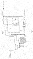
- a wastewater treatment system 1 includes a solid-liquid separator 2, a filter mechanism 3, a first anaerobic treatment tank 4, a second anaerobic treatment tank 5, and a sludge supply mechanism 6.
- the solid-liquid separator 2 is formed by a sedimentation basin for separating a liquid portion and a solid portion from the organic wastewater.
- the solid-liquid separator 2 allows the organic wastewater, from which large trash is removed in advance in a grit tank or the like, to gently flow so that solid organic matter in the organic wastewater settles down.
- Supernatant liquid separated by the solid-liquid separator 2 is sent to the first anaerobic treatment tank 4.
- a solid-liquid separation step of separating the liquid portion and the solid organic matter from the organic wastewater is carried out by the solid-liquid separator 2.
- the first anaerobic treatment tank 4 is a treatment tank for carrying out anaerobic treatment of the liquid portion separated by the solid-liquid separator 2 and obtaining treated water that has passed through the filter mechanism 3 from the sludge.
- the liquid portion separated from the organic wastewater in the solid-liquid separation step i.e., only soluble components are digested by microorganisms. Therefore, the undegraded solid portion does not accumulate in the treatment tank, and digestion treatment can be carried out efficiently in the treatment tank which is not large in capacity.
- a first anaerobic treatment step of carrying out the anaerobic treatment of the liquid portion separated in the solid-liquid separation step and obtaining the treated water, that has passed through the filter mechanism 3, from the sludge is carried out in the first anaerobic treatment tank 4.
- the filter mechanism 3 is formed by a membrane separator 7 and an air diffuser 8 and is immersed and disposed in the sludge in the first anaerobic treatment tank 4.
- the membrane separator 7 is formed by a plurality of membrane elements each of which has separation membranes on its front and back opposite surfaces, and a frame in which the respective membrane elements are housed at intervals.
- a suction pipe provided to each of the membrane elements is connected to a header pipe, and the header pipe is connected to a suction pump.
- the suction pump By driving the suction pump, the treated water is drawn and filtered through the respective separation membranes from the sludge in the first anaerobic treatment tank 4.
- the air diffuser 8 is formed by an air diffusion pipe disposed below the membrane separator 7, and a blower B for supplying gas for air diffusion into the air diffusion pipe. At least biogas such as methane gas produced by the anaerobic treatment in the first anaerobic treatment tank 4 is drawn by the blower B and supplied into the air diffusion pipe. In other words, an air diffusion step of diffusing the biogas, produced in the anaerobic treatment, from below the membrane separator 7 is carried out in the air diffuser 8.
- the filter mechanism is not clogged with the pulverized anaerobic sludge.
- the organic wastewater such as sewerage includes fibrous trash such as toilet paper, and a certain amount of the fiber portion is not degraded in the second anaerobic treatment step and supplied in a loosened and dispersed state to the first anaerobic treatment step.
- the second anaerobic treatment tank 5 is a treatment tank for carrying out the anaerobic treatment of the solid portion separated by the solid-liquid separator 2.
- the second anaerobic treatment tank 5 includes a warming mechanism 9 for warming the sludge in the tank.
- the warming mechanism 9 is formed by a known heat exchanger.
- the organic matter in the solid portion condensed by being separated from the organic wastewater in the solid-liquid separator 2 is solubilized and digested by the microorganisms. Because the anaerobic treatment is carried out with a high concentration of the organic matter, highly active microorganisms greatly proliferate.
- the second anaerobic treatment tank 5 a large amount of flammable gas is produced by the anaerobic treatment of the condensed solid organic matters.
- the flammable gas as fuel for the warming mechanism 9
- favorable digestion treatment is carried out efficiently.
- the highly active microorganisms greatly proliferate in the second anaerobic treatment tank 5.
- the biogas such as methane gas produced in the first anaerobic treatment tank 4 and the second anaerobic treatment tank 5 is captured by a gas holder or the like.
- the second anaerobic treatment step of carrying out the anaerobic treatment of the solid organic matter separated in the solid-liquid separation step is carried out in the second anaerobic treatment tank 5, and the second anaerobic treatment step is carried out in a warmed state.
- the sludge supply mechanism 6 includes a pump P for pumping out the sludge treated in the second anaerobic treatment tank 5, and a conveying pipe for supplying the pumped-out sludge to the first anaerobic treatment tank 4.
- the large amount of highly active microorganisms which have proliferated in the second anaerobic treatment tank 5 is supplied to the first anaerobic treatment tank 4 by the sludge supply mechanism 6. Therefore, in the first anaerobic treatment step, the anaerobic treatment is carried out efficiently by the large amount of highly active microorganisms without warming the sludge.
- the sludge supply step of supplying the sludge in the second anaerobic treatment step to the first anaerobic treatment step is carried out in the sludge supply mechanism 6.
- the microorganisms cultured in the second anaerobic treatment tank 5 include many microorganisms useful in the first anaerobic step, and the sludge including such microorganisms is supplied as seed sludge to the first anaerobic treatment step. Therefore, even in a low water temperature period, the digestion treatment is carried out efficiently with a large amount of activated microorganisms in the first anaerobic treatment tank 4.
- a sludge retention time in the second anaerobic treatment tank 5 is set to be longer than that in the first anaerobic treatment tank 4.
- the anaerobic treatment step and the second anaerobic treatment step are set to be suitable treatment times for the first anaerobic treatment step and the second anaerobic treatment step, respectively. For example, if the sludge retention time in the first anaerobic treatment tank 4 is set to be shorter than 15 days and the sludge retention time in the second anaerobic treatment tank 5 is set to about 15 to 30 days, the anaerobic treatment can be carried out efficiently in each tank.
- the separation membrane of the membrane separator 7 preferably has such a structure as to be able to achieve a BOD of 20 mg/L or less of the treated water that has passed through the separation membrane.
- a microfiltration membrane and an ultrafiltration membrane can be used. It is sufficient that passage of particles having particle diameters of 1 ⁇ m or less through the separation membrane can be prevented.
- Surplus sludge produced in the first anaerobic treatment tank 4 and the second anaerobic treatment tank 5 is pumped out by sludge pumps (not shown) and supplied to and dewatered by a dewatering device 10, and subjected to treatment such as incineration. Filtrate is released into the river or the like together with the treated water from the membrane separator 7.
- An iron-based flocculant may be added to the sludge to be treated in the above-described sedimentation basin 2 or the second anaerobic treatment tank 5. If the iron-based flocculant is added to the sludge to be treated in the sedimentation basin 2 or the second anaerobic treatment tank 5 when phosphorous components are included in the organic wastewater flowing into the sedimentation basin 2 or the second anaerobic treatment tank 5, it is possible to flocculate fine SS and the phosphorous components in the organic wastewater.
- the undegraded solid organic matter and the phosphorous components flowing into the first anaerobic treatment tank 4 can be reduced and the quality of the treated water filtered by the separation membrane of the membrane separator 7 can be further improved.
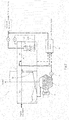
- the sedimentation basin as the solid-liquid separator 2 and the first anaerobic treatment tank 4 are formed by separate tanks in the example described in the above embodiment, the sedimentation basin and the first anaerobic treatment tank 4 may be formed by an integral treatment tank 11 as shown in FIG. 2 .
- the treatment tank 11 With a partition wall 12 provided to the treatment tank 11, the treatment tank 11 is partitioned into a treatment tank 11a which functions as a sedimentation basin and a treatment tank 11b which functions as a first anaerobic treatment tank. Convection of sludge by an air diffuser 8 disposed in the treatment tank 11b is intercepted by the partition wall 12 so as not to influence the treatment tank 11a.
- Supernatant liquid in the treatment tank 11a overflows the partition wall 12 and flows into the treatment tank 11b.
- a cover lid is provided to the treatment tank 11 to maintain the inside of the treatment tank 11 in an anaerobic atmosphere.
- the solid organic matter such as garbage may be put into the second anaerobic treatment tank 5 and subjected to the anaerobic treatment at the same time.
- the undegraded fibrous material included in the garbage is supplied to the first anaerobic treatment tank 4 and functions as a filter aid for cleaning the separation membrane.
- the filter mechanism 3 is formed by the membrane separator 7 including the separation membrane in the example described in the above embodiment, the filter mechanism 3 may be formed by a known porous body such as a mesh filter, a screen, a ceramic, and sponge.
- the filter mechanism 3 preferably has such a structure as to be able to achieve a BOD of 20 mg/L or less of the treated water that has passed through the filter mechanism 3. It is sufficient that passage of particles having particle diameters of 1 ⁇ m or less through the filter mechanism 3 can be prevented.
- the solid-liquid separator 2 is formed by the sedimentation basin in the example described in the above embodiment, the solid-liquid separator 2 may be formed by a screen mechanism such as a bar screen or a centrifugal separation mechanism such as a cyclone.
- the treated water that has passed through the filter mechanism is released as it is into the river or the like in the example described in the above embodiment
- the treated water that has passed through the filter mechanism may be temporarily retained in an aeration tank and gently aerated, biogas such as methane gas dissolved in the treated water may be recovered, and then the treated water may be released into the river or the like.
- a decompression tank may be installed in place of the aeration tank to recover the biogas such as the methane gas dissolved in the treated water by decompression treatment.
- both the biogas and fossil fuel may be used as the fuel or only the fossil fuel may be used as the fuel.
- the treated water obtained by the wastewater treatment system according to the present invention does not comply with an effluent standard set in a region where the system is used, the treated water that has passed through the filter mechanism may be highly clarified by a high level treatment device in order to comply with the effluent standard and then released.
- FIG. 3 Based on FIG. 3 , the high level treatment step and the high level treatment device for the treated water discharged from the first anaerobic treatment tank 4 will be described.
- FIG. 3 structures on an upstream side of the first anaerobic treatment tank 4 shown in FIG. 1 are not shown.
- the wastewater treatment system 1 further includes a nitrification tank 12, an anoxic tank 13, and a solid-liquid separator 14 on the downstream side of the first anaerobic treatment tank 4 in order to carry out high level treatment of the treated water discharged from the filter mechanism 3 of the first anaerobic treatment tank 4.
- an aerator 15 is disposed in the nitrification tank 12. Ammonia included in the treated water flowing in from the first anaerobic treatment tank 4 is nitrified by aeration and turns into nitric acid.
- the sludge that has proliferated in the first anaerobic treatment tank 4 is supplied.
- the sludge maintained in an anoxic state takes in phosphorus included in the treated water supplied from the nitrification tank 12 into the anoxic tank 13, the nitric acid in the treated water is denitrified.
- Supernatant liquid obtained by solid-liquid separation in the solid-liquid separator 14 is released into the river or the like, and the sludge obtained by the solid-liquid separation is returned as return sludge into the first anaerobic treatment tank 4.
- the treated water that has passed through the filter mechanism 3 includes nitrogen and phosphorous and is less contaminated and, as a result, is water suitable as a growing environment for algae. Therefore, as the high level treatment step, algae such as euglena may be used and allowed to photosynthesize in the treated water to thereby carry out denitrification and dephosphorization treatment.
- the wastewater treatment method and the wastewater treatment system according to the present invention described above can be widely applied to domestic wastewater treatment systems such as sewage treatment plants and water clarifier tanks and industrial wastewater treatment systems for food factories and the like.
Landscapes
- Life Sciences & Earth Sciences (AREA)
- Engineering & Computer Science (AREA)
- Water Supply & Treatment (AREA)
- Chemical & Material Sciences (AREA)
- Microbiology (AREA)
- Organic Chemistry (AREA)
- Environmental & Geological Engineering (AREA)
- Hydrology & Water Resources (AREA)
- Biodiversity & Conservation Biology (AREA)
- Chemical Kinetics & Catalysis (AREA)
- Sustainable Development (AREA)
- General Chemical & Material Sciences (AREA)
- Oil, Petroleum & Natural Gas (AREA)
- Health & Medical Sciences (AREA)
- Molecular Biology (AREA)
- Separation Using Semi-Permeable Membranes (AREA)
- Purification Treatments By Anaerobic Or Anaerobic And Aerobic Bacteria Or Animals (AREA)
- Treatment Of Sludge (AREA)
Abstract
Description
- The present invention relates to a wastewater treatment method and a wastewater treatment system for carrying out biological treatment of organic wastewater under anaerobic conditions.
- To carry out clarification treatment of organic wastewater such as sewerage and domestic wastewater with a COD of 1000 mg/L or less, sufficient quality of treated water cannot be obtained only by anaerobic treatment in which biological treatment is carried out under an anaerobic condition and therefore biological treatment under an aerobic condition is carried out in general.
- Disclosed in Patent Document 1 is a wastewater treatment method of removing SS, included in a large volume of influent sewerage, by sedimentation in a primary sedimentation basin and then carrying out biological treatment of supernatant liquid, from the primary sedimentation basin, in an aerobic treatment tank, in order to reduce a load of aerobic treatment.
- In this wastewater treatment method, the SS removed by sedimentation in the primary sedimentation basin is subjected to digestion treatment in a digester tank, a solid portion is removed after the digestion treatment by sedimentation separation or dewatering, and only a remaining liquid portion is returned into the primary sedimentation basin.
- On the other hand, in order to carry out clarification treatment of organic wastewater with a COD of 1000 mg/L or less, utilization of an UASB (up-flow anaerobic sludge blanket) method is developed, the method utilizing self-aggregation properties of anaerobic microorganisms to thereby retain highly-active bacteria as granules having excellent settling properties in a treatment tank.
- However, to employ the UASB method, quality of the treated water is insufficient and therefore aerobic treatment is required in a subsequent stage. Because the UASB method is a method suitable for treatment of high concentration organic wastewater, an amount of methane gas that is required to warm the treatment tank cannot be obtained by carrying out the anaerobic treatment of the low concentration organic wastewater such as sewerage. Therefore, it is impossible to warm the treatment tank from an economical viewpoint, which reduces a property of degrading a solid portion.
- [Patent Document 1] Japanese Patent No.
3664399 - In the conventional wastewater treatment method under the anaerobic condition, an aerobic treatment step of diffusing a large amount of air in the treatment tank is required in order to secure predetermined water quality at the end, and power cost for a blower or the like for air diffusion increases.
- On the other hand, there is an efficient sludge treatment method attracting attention, in which sludge concentration is increased by warming sludge in an anaerobic treatment step and treated water is obtained by filtering the sludge with a filter mechanism. In this method, methane gas generated in the anaerobic treatment step is used as fuel for warming.
- However, when the wastewater having a low organic concentration and including undegraded solid organic matter is subjected to the biological treatment under the anaerobic condition, a sufficient amount of methane gas to heat the sludge cannot be obtained. If another heat source is used for this purpose, energy cost increases. If the treatment is carried out without warming the sludge, treatment efficiency seriously reduces and the undegraded solid portion accumulates in the treatment tank.
- Even in this situation, the treatment can be carried out smoothly by securing sufficient sludge retention time SRT. For this purpose, however, it is necessary to increase a capacity of the treatment tank.
- Moreover, when the treated water is obtained by filtering the sludge in the anaerobic treatment step with the filter mechanism such as a membrane separator, microorganisms and undegraded matter in the sludge adhere to a surface of a filter element such as a separation membrane to clog filter holes, which impairs filtration properties.
- If the solid portion included in the influent wastewater is removed in advance as in Patent Document 1, the sludge to be treated in the anaerobic treatment step mainly includes soluble components, and thus it is possible to avoid a case where the undegraded matter adhere to the surface of the filter element.
- However, the components which serve as cores required when the microorganisms form flocks reduce and therefore the sludge becomes pulverized. Moreover, a fiber portion which is effective for improvement of the filtration properties also reduces, which in turn reduces filtration performance of the filter mechanism.
- In view of the above problems, it is an object of the present invention to provide a wastewater treatment method and a wastewater treatment system which do not require special aerobic treatment without increasing the size of anaerobic treatment tanks and without reducing performance of a filter mechanism.
- To achieve the above object, a first characteristic structure of a wastewater treatment method according to the present invention is, as described in claim 1, a wastewater treatment method of carrying out biological treatment of organic wastewater under an anaerobic condition, the method including: a solid-liquid separation step of separating a liquid portion and a solid portion from the organic wastewater; a first anaerobic treatment step of carrying out anaerobic treatment of the liquid portion separated in the solid-liquid separation step and obtaining treated water, that has passed through a filter mechanism, from sludge in the anaerobic treatment; a second anaerobic treatment step of carrying out anaerobic treatment of the solid portion separated in the solid-liquid separation step; and a sludge supply step of supplying the sludge treated in the second anaerobic treatment step to the first anaerobic treatment step.
- In the first anaerobic treatment step, the liquid portion separated from the organic wastewater in the solid-liquid separation step, i.e., only soluble components are digested by microorganisms. Therefore, the undegraded solid portion does not accumulate in the treatment tank and digestion treatment can be carried out efficiently in the treatment tank which is not large in capacity.
- In the second anaerobic treatment step, the organic matter in the solid portion condensed by being separated from the organic wastewater in the solid-liquid separation step is solubilized and digested by the microorganisms. Because the anaerobic treatment is carried out with a high concentration of the organic matter in the second anaerobic treatment step, highly active microorganisms greatly proliferate. The sludge is supplied in the sludge supply step to the first anaerobic treatment step and therefore the anaerobic treatment is carried out efficiently with a large amount of activated microorganisms in the first anaerobic treatment step without warming of the sludge.
- As a result, as compared with a case in which the organic wastewater is treated as it is in the first anaerobic treatment step without going through the solid-liquid separation step, the treatment can be carried out in a much smaller treatment tank while securing the sufficient SRT in the above-described second anaerobic treatment step.
- Furthermore, because the solid portion is removed in advance from the organic wastewater to be treated in the first anaerobic treatment step, undegraded solid matter does not adhere to a filter element such as the separation membrane forming the filter mechanism.
- Even if the anaerobic sludge becomes pulverized in the first anaerobic treatment step, a large amount of fibrous material is included in the sludge supplied from the second anaerobic treatment step and therefore the fibrous material appropriately cleans the filter mechanism.
- As a result, satisfactory quality of the treated water filtered by the filter mechanism can be secured and therefore it is possible to release the treated water as it is into a river or the like without carrying out special aerobic treatment step.
- As described in
claim 2, in addition to the above-described first characteristic structure, a second characteristic structure of the wastewater treatment method according to the present invention is that the filter mechanism used in the first anaerobic treatment step is a membrane separator. The membrane separator can be suitably used as the filter mechanism. - As described in
claim 3, in addition to the above-described second characteristic structure, a third characteristic structure of the wastewater treatment method according to the present invention is that the first anaerobic treatment step includes an air diffusion step of diffusing biogas, produced in the anaerobic treatment, from below the membrane separator immersed and disposed in the sludge. - The biogas such as the methane gas produced in the digestion treatment is diffused from below the membrane separator in the air diffusion step. An upward stream produced in the sludge by the air diffusion peels off clogging material adhering to a separation membrane surface of the filter mechanism and therefore satisfactory filtration performance is maintained.
- Moreover, because trash such as fibrous material which remains undegraded in the second anaerobic treatment step is supplied to the first anaerobic treatment step, the fibrous material floating along the upward stream generated in the sludge by the air diffusion comes in contact with and easily peels off the clogging material adhering to the membrane surface of the filter mechanism.
- As described in
claim 4, in addition to the above-described first characteristic structure, a fourth characteristic structure of the wastewater treatment method according to the present invention is that the second anaerobic treatment step is carried out in a warmed state in which the sludge is warmed. - As described in
claim 5, in addition to the above-described third characteristic structure, a fifth characteristic structure of the wastewater treatment method according to the present invention is that the second anaerobic treatment step is carried out in a warmed state in which the sludge is warmed. - As described in
claim 6, in addition to the above-described fourth or fifth characteristic structure, a sixth characteristic structure of the wastewater treatment method according to the present invention is that the second anaerobic treatment step is carried out in the warmed state in which the sludge is warmed by using biogas, produced in the second anaerobic treatment step, as fuel. - Because the solid organic matter is condensed in the solid-liquid separation step and supplied to the second anaerobic treatment step, a large amount of flammable gas is produced by the anaerobic treatment in the second anaerobic treatment step. In a warmed environment obtained by using the flammable gas as fuel, favorable digestion treatment is carried out efficiently. As a result, the highly active microorganisms greatly proliferating in the second anaerobic treatment step can be supplied to the first anaerobic treatment step.
- As described in
claim 7, in addition to any one of the above-described first to fifth characteristic structures, a seventh characteristic structure of the wastewater treatment method according to the present invention is that a sludge retention time in the second anaerobic treatment step is set to be longer than a sludge retention time in the first anaerobic treatment step. - As described in
claim 8, in addition to any one of the above-described first to fifth characteristic structures, an eighth characteristic structure of the wastewater treatment method according to the present invention is that the sludge retention time in the second anaerobic treatment step is set to 15 to 30 days and the sludge retention time in the first anaerobic treatment step is set to be shorter than 15 days. - By separating the low concentration and large flow liquid portion and high concentration and small flow solid portion from each other, setting the sludge retention time in the first anaerobic treatment step of treating the liquid portion to a shorter time, and setting the sludge retention time in the second anaerobic treatment step of treating the solid portion to a longer time, it is possible to reduce capacities of the treatment tanks.
- As described in
claim 9, in addition to any one of the above-described first to fifth characteristic structures, a ninth characteristic structure of the wastewater treatment method according to the present invention is that the method further includes a recovery step of recovering biogas, dissolved in the treated water that has passed through the filter mechanism, by aeration treatment or decompression treatment. - By recovering the biogas dissolved in the treated water, the biogas can be effectively used as the fuel and it is possible to suppress emission of methane gas which is greenhouse gas.
- As described in
claim 10, in addition to any one of the above-described first to fifth characteristic structures, a tenth characteristic structure of the wastewater treatment method according to the present invention is that the method further includes: a nitrification step of turning ammonia, dissolved in the treated water that has passed through the filter mechanism, into nitric acid; a denitrification step of denitrifying the nitric acid produced in the nitrification step; and a solid-liquid separation step of separating sludge from treated water that has gone through the denitrification step. - By carrying out high level treatment of the treated water separated by the filter mechanism, it is possible to adapt to an effluent standard in a region where the treated water is to be released.
- As described in claim 11, a first characteristic structure of a wastewater treatment system according to the present invention is a wastewater treatment system for carrying out biological treatment of organic wastewater under an anaerobic condition, the system including: a solid-liquid separator for separating a liquid portion and a solid portion from the organic wastewater; a first anaerobic treatment tank for carrying out anaerobic treatment of the liquid portion separated by the solid-liquid separator and obtaining treated water, that has passed through a filter mechanism, from sludge in the anaerobic treatment; a second anaerobic treatment tank for carrying out anaerobic treatment of the solid portion separated by the solid-liquid separator; and a sludge supply mechanism for supplying the sludge in the second anaerobic treatment tank into the first anaerobic treatment tank.
- As described in
claim 12, in addition to the above-described first characteristic structure, a second characteristic structure of the wastewater treatment system according to the present invention is that the filter mechanism provided to the first anaerobic treatment tank is a membrane separator. - As described in
claim 13, in addition to the above-described first characteristic structure, a third characteristic structure of the wastewater treatment system according to the present invention is that the filter mechanism includes a membrane separator immersed and disposed in the sludge in the first anaerobic treatment tank, and an air diffuser disposed below the membrane separator to diffuse biogas produced in the anaerobic treatment. - As described in
claim 14, in addition to the above-described first characteristic structure, a fourth characteristic structure of the wastewater treatment system according to the present invention is that the filter mechanism is a member that is selected from a mesh filter, a screen, a ceramic porous body, and a sponge porous body and that prevents passage of a particle having a particle diameter of 1 µm or less. - As described in
claim 15, in addition to any one of the above-described first to fourth characteristic structures, a fifth characteristic structure of the wastewater treatment system according to the present invention is that the second anaerobic treatment tank includes a warming mechanism for warming the sludge in the tank. - As described in claim 16, in addition to any one of the above-described first to fourth characteristic structures, a sixth characteristic structure of the wastewater treatment system according to the present invention is that the system further includes: a nitrification tank for turning ammonia, dissolved in the treated water that has been separated by the filter mechanism, into nitric acid; an anoxic tank for denitrifying the nitric acid produced in the nitrification tank; and a solid-liquid separator for separating sludge from treated water that has passed through the anoxic tank.
- As described above, according to the present invention, it is possible to provide the wastewater treatment method and the wastewater treatment system which do not require special aerobic treatment without increasing the size of the anaerobic treatment tanks and without reducing the performance of the filter mechanism.
-
-
FIG. 1 is an explanatory view of a wastewater treatment system. -
FIG. 2 is an explanatory view of a wastewater treatment system according to another embodiment. -
FIG. 3 is an explanatory view of high level treatment. - A wastewater treatment method and a wastewater treatment system according to the present invention and for carrying out biological treatment of organic wastewater under anaerobic conditions will be described. The term, "biogas" used in the following description is defined as "flammable gas produced by fermentation or decay of organic matter".
- As shown in
FIG. 1 , a wastewater treatment system 1 includes a solid-liquid separator 2, afilter mechanism 3, a firstanaerobic treatment tank 4, a secondanaerobic treatment tank 5, and asludge supply mechanism 6. - The solid-
liquid separator 2 is formed by a sedimentation basin for separating a liquid portion and a solid portion from the organic wastewater. The solid-liquid separator 2 allows the organic wastewater, from which large trash is removed in advance in a grit tank or the like, to gently flow so that solid organic matter in the organic wastewater settles down. Supernatant liquid separated by the solid-liquid separator 2 is sent to the firstanaerobic treatment tank 4. In other words, a solid-liquid separation step of separating the liquid portion and the solid organic matter from the organic wastewater is carried out by the solid-liquid separator 2. - The first
anaerobic treatment tank 4 is a treatment tank for carrying out anaerobic treatment of the liquid portion separated by the solid-liquid separator 2 and obtaining treated water that has passed through thefilter mechanism 3 from the sludge. - In the first
anaerobic treatment tank 4, the liquid portion separated from the organic wastewater in the solid-liquid separation step, i.e., only soluble components are digested by microorganisms. Therefore, the undegraded solid portion does not accumulate in the treatment tank, and digestion treatment can be carried out efficiently in the treatment tank which is not large in capacity. - In other words, a first anaerobic treatment step of carrying out the anaerobic treatment of the liquid portion separated in the solid-liquid separation step and obtaining the treated water, that has passed through the
filter mechanism 3, from the sludge is carried out in the firstanaerobic treatment tank 4. - The
filter mechanism 3 is formed by amembrane separator 7 and anair diffuser 8 and is immersed and disposed in the sludge in the firstanaerobic treatment tank 4. Themembrane separator 7 is formed by a plurality of membrane elements each of which has separation membranes on its front and back opposite surfaces, and a frame in which the respective membrane elements are housed at intervals. - A suction pipe provided to each of the membrane elements is connected to a header pipe, and the header pipe is connected to a suction pump. By driving the suction pump, the treated water is drawn and filtered through the respective separation membranes from the sludge in the first
anaerobic treatment tank 4. - The
air diffuser 8 is formed by an air diffusion pipe disposed below themembrane separator 7, and a blower B for supplying gas for air diffusion into the air diffusion pipe. At least biogas such as methane gas produced by the anaerobic treatment in the firstanaerobic treatment tank 4 is drawn by the blower B and supplied into the air diffusion pipe. In other words, an air diffusion step of diffusing the biogas, produced in the anaerobic treatment, from below themembrane separator 7 is carried out in theair diffuser 8. - By diffusing the biogas, such as methane gas produced in the anaerobic treatment, from the
air diffuser 8, an upward stream is produced in the intervals between the respective membrane elements in the tank, and the upward stream peels off clogging material adhering to membrane surfaces of the separation membranes. - Because the solid organic matter is removed in advance from the organic wastewater that flows into the first
anaerobic treatment tank 4, filtration performance is not reduced by adhesion of a large amount of solid organic matter to thefilter mechanism 3. - Even if the anaerobic sludge becomes pulverized in the first
anaerobic treatment tank 4, a large amount of fibrous material is included in the sludge supplied from the secondanaerobic treatment tank 5 to the firstanaerobic treatment tank 4 through thesludge supply mechanism 6 which will be described later, and therefore the fibrous material appropriately cleans thefilter mechanism 3. - Because the fibrous material acts as filter aids in the
filter mechanism 3, the filter mechanism is not clogged with the pulverized anaerobic sludge. For example, the organic wastewater such as sewerage includes fibrous trash such as toilet paper, and a certain amount of the fiber portion is not degraded in the second anaerobic treatment step and supplied in a loosened and dispersed state to the first anaerobic treatment step. - The second
anaerobic treatment tank 5 is a treatment tank for carrying out the anaerobic treatment of the solid portion separated by the solid-liquid separator 2. The secondanaerobic treatment tank 5 includes awarming mechanism 9 for warming the sludge in the tank. Thewarming mechanism 9 is formed by a known heat exchanger. - In the second
anaerobic treatment tank 5, the organic matter in the solid portion condensed by being separated from the organic wastewater in the solid-liquid separator 2 is solubilized and digested by the microorganisms. Because the anaerobic treatment is carried out with a high concentration of the organic matter, highly active microorganisms greatly proliferate. - Furthermore, in the second
anaerobic treatment tank 5, a large amount of flammable gas is produced by the anaerobic treatment of the condensed solid organic matters. By using the flammable gas as fuel for thewarming mechanism 9, favorable digestion treatment is carried out efficiently. As a result, the highly active microorganisms greatly proliferate in the secondanaerobic treatment tank 5. Herein, the biogas such as methane gas produced in the firstanaerobic treatment tank 4 and the secondanaerobic treatment tank 5 is captured by a gas holder or the like. - In other words, the second anaerobic treatment step of carrying out the anaerobic treatment of the solid organic matter separated in the solid-liquid separation step is carried out in the second
anaerobic treatment tank 5, and the second anaerobic treatment step is carried out in a warmed state. - The
sludge supply mechanism 6 includes a pump P for pumping out the sludge treated in the secondanaerobic treatment tank 5, and a conveying pipe for supplying the pumped-out sludge to the firstanaerobic treatment tank 4. The large amount of highly active microorganisms which have proliferated in the secondanaerobic treatment tank 5 is supplied to the firstanaerobic treatment tank 4 by thesludge supply mechanism 6. Therefore, in the first anaerobic treatment step, the anaerobic treatment is carried out efficiently by the large amount of highly active microorganisms without warming the sludge. - In other words, the sludge supply step of supplying the sludge in the second anaerobic treatment step to the first anaerobic treatment step is carried out in the
sludge supply mechanism 6. - It is sufficient to treat the Liquid portion mainly including the soluble components out of the organic wastewater in the first
anaerobic treatment tank 4, and it is sufficient to treat the condensed solid portion out of the organic wastewater in the secondanaerobic treatment tank 5. Because the object to be treated is different between the first anaerobic treatment step and the second anaerobic treatment step and the microorganisms suitable for each object to be treated proliferate efficiently, it is possible to efficiently carry out the anaerobic treatment. - In the sludge supply step, the microorganisms cultured in the second
anaerobic treatment tank 5 include many microorganisms useful in the first anaerobic step, and the sludge including such microorganisms is supplied as seed sludge to the first anaerobic treatment step. Therefore, even in a low water temperature period, the digestion treatment is carried out efficiently with a large amount of activated microorganisms in the firstanaerobic treatment tank 4. - In other words, only the sludge in the second
anaerobic treatment tank 5 is warmed, and the sludge in the firstanaerobic treatment tank 4 need not be warmed, which significantly reduces fuel required for the warming treatment of the sludge. - In a wastewater treatment system according to the present invention, a sludge retention time in the second
anaerobic treatment tank 5 is set to be longer than that in the firstanaerobic treatment tank 4. - In the second
anaerobic treatment tank 5, because the solid organic matter that has been condensed and reduced in volume is subjected to the anaerobic treatment, a large treatment tank is not required, though digestion takes a sufficiently long time. - Therefore, it is possible to set suitable treatment times for the first anaerobic treatment step and the second anaerobic treatment step, respectively. For example, if the sludge retention time in the first
anaerobic treatment tank 4 is set to be shorter than 15 days and the sludge retention time in the secondanaerobic treatment tank 5 is set to about 15 to 30 days, the anaerobic treatment can be carried out efficiently in each tank. - With the wastewater treatment system according to the present invention, satisfactory quality of the treated water filtered by the
membrane separator 7 can be secured and therefore it is possible to release the treated water as it is into a river or the like without carrying out special aerobic treatment of the filtered treated water. - The separation membrane of the
membrane separator 7 preferably has such a structure as to be able to achieve a BOD of 20 mg/L or less of the treated water that has passed through the separation membrane. For example, a microfiltration membrane and an ultrafiltration membrane can be used. It is sufficient that passage of particles having particle diameters of 1 µm or less through the separation membrane can be prevented. - Surplus sludge produced in the first
anaerobic treatment tank 4 and the secondanaerobic treatment tank 5 is pumped out by sludge pumps (not shown) and supplied to and dewatered by adewatering device 10, and subjected to treatment such as incineration. Filtrate is released into the river or the like together with the treated water from themembrane separator 7. - An iron-based flocculant may be added to the sludge to be treated in the above-described
sedimentation basin 2 or the secondanaerobic treatment tank 5. If the iron-based flocculant is added to the sludge to be treated in thesedimentation basin 2 or the secondanaerobic treatment tank 5 when phosphorous components are included in the organic wastewater flowing into thesedimentation basin 2 or the secondanaerobic treatment tank 5, it is possible to flocculate fine SS and the phosphorous components in the organic wastewater. - In this way, the undegraded solid organic matter and the phosphorous components flowing into the first
anaerobic treatment tank 4 can be reduced and the quality of the treated water filtered by the separation membrane of themembrane separator 7 can be further improved. - Another embodiment of the wastewater treatment method and the wastewater treatment system according to the present invention will be described below. Similar structures to those in the above-described embodiment will be provided with the same reference numerals and will not be described.
- Although the sedimentation basin as the solid-
liquid separator 2 and the firstanaerobic treatment tank 4 are formed by separate tanks in the example described in the above embodiment, the sedimentation basin and the firstanaerobic treatment tank 4 may be formed by an integral treatment tank 11 as shown inFIG. 2 . - With a
partition wall 12 provided to the treatment tank 11, the treatment tank 11 is partitioned into atreatment tank 11a which functions as a sedimentation basin and atreatment tank 11b which functions as a first anaerobic treatment tank. Convection of sludge by anair diffuser 8 disposed in thetreatment tank 11b is intercepted by thepartition wall 12 so as not to influence thetreatment tank 11a. - Supernatant liquid in the
treatment tank 11a overflows thepartition wall 12 and flows into thetreatment tank 11b. In this structure, a cover lid is provided to the treatment tank 11 to maintain the inside of the treatment tank 11 in an anaerobic atmosphere. - Although only the solid portion separated in the
sedimentation basin 2 is subjected to the anaerobic treatment in the secondanaerobic treatment tank 5 in the example described in the above embodiment, the solid organic matter such as garbage may be put into the secondanaerobic treatment tank 5 and subjected to the anaerobic treatment at the same time. - If the treatment is carried out in this manner, even when the organic wastewater flowing into the
sedimentation basin 2 does not include the undegraded fibrous material, the undegraded fibrous material included in the garbage is supplied to the firstanaerobic treatment tank 4 and functions as a filter aid for cleaning the separation membrane. - Although the
filter mechanism 3 is formed by themembrane separator 7 including the separation membrane in the example described in the above embodiment, thefilter mechanism 3 may be formed by a known porous body such as a mesh filter, a screen, a ceramic, and sponge. Thefilter mechanism 3 preferably has such a structure as to be able to achieve a BOD of 20 mg/L or less of the treated water that has passed through thefilter mechanism 3. It is sufficient that passage of particles having particle diameters of 1 µm or less through thefilter mechanism 3 can be prevented. - Although the solid-
liquid separator 2 is formed by the sedimentation basin in the example described in the above embodiment, the solid-liquid separator 2 may be formed by a screen mechanism such as a bar screen or a centrifugal separation mechanism such as a cyclone. - Although the treated water that has passed through the filter mechanism is released as it is into the river or the like in the example described in the above embodiment, the treated water that has passed through the filter mechanism may be temporarily retained in an aeration tank and gently aerated, biogas such as methane gas dissolved in the treated water may be recovered, and then the treated water may be released into the river or the like. Alternatively, a decompression tank may be installed in place of the aeration tank to recover the biogas such as the methane gas dissolved in the treated water by decompression treatment.
- Although the biogas such as methane gas produced in the first
anaerobic treatment tank 4 and the secondanaerobic treatment tank 5 is supplied as the fuel to thewarming mechanism 9 and thewarming mechanism 9 warms the sludge in the secondanaerobic treatment tank 5 in the structure described in the above embodiment, both the biogas and fossil fuel may be used as the fuel or only the fossil fuel may be used as the fuel. - If the treated water obtained by the wastewater treatment system according to the present invention does not comply with an effluent standard set in a region where the system is used, the treated water that has passed through the filter mechanism may be highly clarified by a high level treatment device in order to comply with the effluent standard and then released.
- Based on
FIG. 3 , the high level treatment step and the high level treatment device for the treated water discharged from the firstanaerobic treatment tank 4 will be described. InFIG. 3 , structures on an upstream side of the firstanaerobic treatment tank 4 shown inFIG. 1 are not shown. - The wastewater treatment system 1 further includes a
nitrification tank 12, ananoxic tank 13, and a solid-liquid separator 14 on the downstream side of the firstanaerobic treatment tank 4 in order to carry out high level treatment of the treated water discharged from thefilter mechanism 3 of the firstanaerobic treatment tank 4. - In the
nitrification tank 12, anaerator 15 is disposed. Ammonia included in the treated water flowing in from the firstanaerobic treatment tank 4 is nitrified by aeration and turns into nitric acid. - Into the
anoxic tank 13, the sludge that has proliferated in the firstanaerobic treatment tank 4 is supplied. When the sludge maintained in an anoxic state takes in phosphorus included in the treated water supplied from thenitrification tank 12 into theanoxic tank 13, the nitric acid in the treated water is denitrified. - Supernatant liquid obtained by solid-liquid separation in the solid-
liquid separator 14 is released into the river or the like, and the sludge obtained by the solid-liquid separation is returned as return sludge into the firstanaerobic treatment tank 4. - The treated water that has passed through the
filter mechanism 3 includes nitrogen and phosphorous and is less contaminated and, as a result, is water suitable as a growing environment for algae. Therefore, as the high level treatment step, algae such as euglena may be used and allowed to photosynthesize in the treated water to thereby carry out denitrification and dephosphorization treatment. - The wastewater treatment method and the wastewater treatment system according to the present invention described above can be widely applied to domestic wastewater treatment systems such as sewage treatment plants and water clarifier tanks and industrial wastewater treatment systems for food factories and the like.
- Needless to say, the above respective embodiments are merely modes of the present invention, the description does not restrict the scope of the present invention, and specific structures of the respective portions and processes can be suitably changed in design as far as the effects of the present invention are exerted.
-
- 1:
- wastewater treatment system
- 2:
- solid-liquid separator
- 3:
- filter mechanism
- 4:
- first anaerobic treatment tank
- 5:
- second anaerobic treatment tank
- 6:
- sludge supply mechanism
- 7:
- membrane separator
- 8:
- air diffuser
- 9:
- warming mechanism
- 10:
- dewatering device
Claims (16)
- A wastewater treatment method of carrying out biological treatment of organic wastewater under an anaerobic condition,
the method comprising:a solid-liquid separation step of separating a liquid portion and a solid portion from the organic wastewater;a first anaerobic treatment step of carrying out anaerobic treatment of the liquid portion separated in the solid-liquid separation step and obtaining treated water, that has passed through a filter mechanism, from sludge in the anaerobic treatment;a second anaerobic treatment step of carrying out anaerobic treatment of the solid portion separated in the solid-liquid separation step; anda sludge supply step of supplying the sludge treated in the second anaerobic treatment step to the first anaerobic treatment step. - The wastewater treatment method according to claim 1,
wherein the filter mechanism used in the first anaerobic treatment step is a membrane separator. - The wastewater treatment method according to claim 2,
wherein the first anaerobic treatment step includes an air diffusion step of diffusing biogas, produced in the anaerobic treatment, from below the membrane separator immersed and disposed in the sludge. - The wastewater treatment method according to claim 1,
wherein the second anaerobic treatment step is carried out in a warmed state in which the sludge is warmed. - The wastewater treatment method according to claim 3,
wherein the second anaerobic treatment step is carried out in a warmed state in which the sludge is warmed. - The wastewater treatment method according to claim 4 or 5,
wherein the second anaerobic treatment step is carried out in the warmed state in which the sludge is warmed by using biogas, produced in the second anaerobic treatment step, as fuel. - The wastewater treatment method according to any one of claims 1 to 5,
wherein a sludge retention time in the second anaerobic treatment step is set to be longer than a sludge retention time in the first anaerobic treatment step. - The wastewater treatment method according to any one of claims 1 to 5,
wherein the sludge retention time in the second anaerobic treatment step is set to 15 to 30 days and the sludge retention time in the first anaerobic treatment step is set to be shorter than 15 days. - The wastewater treatment method according to any one of claims 1 to 5, further comprising:a recovery step of recovering biogas, dissolved in the treated water that has passed through the filter mechanism, by aeration treatment or decompression treatment.
- The wastewater treatment method according to any one of claims 1 to 5, further comprising:a nitrification step of turning ammonia, dissolved in the treated water that has passed through the filter mechanism, into nitric acid;a denitrification step of denitrifying the nitric acid produced in the nitrification step; anda solid-liquid separation step of separating sludge from treated water that has gone through the denitrification step.
- A wastewater treatment system for carrying out biological treatment of organic wastewater under an anaerobic condition,
the system comprising:a solid-liquid separator for separating a liquid portion and a solid portion from the organic wastewater;a first anaerobic treatment tank for carrying out anaerobic treatment of the liquid portion separated by the solid-liquid separator and obtaining treated water, that has passed through a filter mechanism, from sludge in the anaerobic treatment;a second anaerobic treatment tank for carrying out anaerobic treatment of the solid portion separated by the solid-liquid separator; anda sludge supply mechanism for supplying the sludge in the second anaerobic treatment tank into the first anaerobic treatment tank. - The wastewater treatment system according to claim 11,
wherein the filter mechanism provided to the first anaerobic treatment tank is a membrane separator. - The wastewater treatment system according to claim 11,
wherein the filter mechanism includes
a membrane separator immersed and disposed in the sludge in the first anaerobic treatment tank, and
an air diffuser disposed below the membrane separator to diffuse biogas produced in the anaerobic treatment. - The wastewater treatment system according to claim 11,
wherein the filter mechanism is a member that is selected from a mesh filter, a screen, a ceramic porous body, and a sponge porous body and that prevents passage of a particle having a particle diameter of 1 µm or less. - The wastewater treatment system according to any one of claims 11 to 14,
wherein the second anaerobic treatment tank includes a warming mechanism for warming the sludge in the tank. - The wastewater treatment system according to any one of claims 11 to 14, further comprising:a nitrification tank for turning ammonia, dissolved in the treated water that has been separated by the filter mechanism, into nitric acid;an anoxic tank for denitrifying the nitric acid produced in the nitrification tank; anda solid-liquid separator for separating sludge from treated water that has passed through the anoxic tank.
Applications Claiming Priority (2)
| Application Number | Priority Date | Filing Date | Title |
|---|---|---|---|
| JP2011074956A JP5867796B2 (en) | 2011-03-30 | 2011-03-30 | Waste water treatment method and waste water treatment system |
| PCT/JP2012/057889 WO2012133386A1 (en) | 2011-03-30 | 2012-03-27 | Wastewater treatment method and wastewater treatment system |
Publications (2)
| Publication Number | Publication Date |
|---|---|
| EP2692700A1 true EP2692700A1 (en) | 2014-02-05 |
| EP2692700A4 EP2692700A4 (en) | 2014-10-15 |
Family
ID=46931103
Family Applications (1)
| Application Number | Title | Priority Date | Filing Date |
|---|---|---|---|
| EP12763898.9A Withdrawn EP2692700A4 (en) | 2011-03-30 | 2012-03-27 | METHOD AND SYSTEM FOR TREATING WASTEWATER |
Country Status (6)
| Country | Link |
|---|---|
| US (1) | US20140014577A1 (en) |
| EP (1) | EP2692700A4 (en) |
| JP (1) | JP5867796B2 (en) |
| CN (1) | CN103298754B (en) |
| PH (1) | PH12013501566A1 (en) |
| WO (1) | WO2012133386A1 (en) |
Families Citing this family (9)
| Publication number | Priority date | Publication date | Assignee | Title |
|---|---|---|---|---|
| US8999036B2 (en) * | 2012-09-26 | 2015-04-07 | Stearns Conrad Schmidt Consulting Engineers, Inc. | Method for production of a compressed natural gas equivalent from landfill gas and other biogases |
| AT513378B1 (en) * | 2012-11-13 | 2014-04-15 | Univ Wien Tech | Selective separation of water with simultaneous biomass and media component retention |
| JP6071587B2 (en) * | 2013-01-28 | 2017-02-01 | 大阪瓦斯株式会社 | Waste water treatment apparatus and operation method thereof |
| KR101394888B1 (en) * | 2013-04-29 | 2014-05-14 | (주)전테크 | 1,4-dioxane-containing wastewater treatment method and disposal plant |
| JP6113611B2 (en) * | 2013-09-09 | 2017-04-12 | 株式会社東芝 | Organic wastewater treatment system |
| CN104891738B (en) * | 2015-05-27 | 2016-09-28 | 广东梅雁吉祥水电股份有限公司 | A kind of ecological treatment method of municipal sewage |
| US9833741B2 (en) * | 2015-08-24 | 2017-12-05 | Doosan Heavy Industries & Constructions Co., Ltd. | Submerged membrane filtration system using reciprocating membrane |
| SG10201610914YA (en) * | 2016-12-28 | 2018-07-30 | Meidensha Electric Mfg Co Ltd | Membrane separation method and apparatus equipped with particle fractionator |
| CN112678992B (en) * | 2020-12-15 | 2021-08-13 | 吉林建筑大学 | How to reuse farmland drainage |
Family Cites Families (15)
| Publication number | Priority date | Publication date | Assignee | Title |
|---|---|---|---|---|
| JPS5748397A (en) * | 1980-09-05 | 1982-03-19 | Ebara Infilco Co Ltd | Methane fermentation of organic waste matter |
| JPS62168598A (en) * | 1986-01-17 | 1987-07-24 | Hitachi Plant Eng & Constr Co Ltd | Methane fermenting device |
| JPH0698360B2 (en) * | 1990-09-20 | 1994-12-07 | 荏原インフイルコ株式会社 | Method and apparatus for treating night soil wastewater |
| JPH0647119B2 (en) * | 1990-09-21 | 1994-06-22 | 荏原インフイルコ株式会社 | Combined treatment method of human waste and septic tank sludge |
| JP3172965B2 (en) * | 1995-10-30 | 2001-06-04 | 株式会社荏原製作所 | Sewage treatment method |
| JP2000263018A (en) * | 1999-03-15 | 2000-09-26 | Toshiba Corp | Organic waste treatment equipment |
| JP3856275B2 (en) * | 1999-07-07 | 2006-12-13 | 株式会社荏原製作所 | Method and apparatus for anaerobic treatment of oil-containing wastewater |
| JP3664399B2 (en) | 2002-11-12 | 2005-06-22 | 株式会社荏原製作所 | Organic wastewater and sludge treatment method and treatment equipment |
| JP4901109B2 (en) * | 2005-02-18 | 2012-03-21 | 大阪瓦斯株式会社 | Wastewater treatment system |
| JP5235643B2 (en) * | 2008-12-16 | 2013-07-10 | 大阪瓦斯株式会社 | Method and apparatus for treating organic waste by combined methane fermentation |
| JP5246665B2 (en) * | 2009-03-10 | 2013-07-24 | 株式会社クボタ | Methane fermentation treatment apparatus and methane fermentation treatment method |
| JP5371510B2 (en) * | 2009-03-27 | 2013-12-18 | 大阪瓦斯株式会社 | Combined treatment of wastewater and organic residue |
| JP2009154156A (en) * | 2009-04-02 | 2009-07-16 | Toshiba Corp | Anaerobic water treatment device |
| KR100981187B1 (en) * | 2010-03-09 | 2010-09-10 | 한밭대학교 산학협력단 | Multi-stage type dry anaerobic digestion reactor |
| US8580113B2 (en) * | 2010-08-31 | 2013-11-12 | Zenon Technology Partnership | Method for utilizing internally generated biogas for closed membrane system operation |
-
2011
- 2011-03-30 JP JP2011074956A patent/JP5867796B2/en active Active
-
2012
- 2012-03-27 EP EP12763898.9A patent/EP2692700A4/en not_active Withdrawn
- 2012-03-27 PH PH1/2013/501566A patent/PH12013501566A1/en unknown
- 2012-03-27 US US14/005,966 patent/US20140014577A1/en not_active Abandoned
- 2012-03-27 CN CN201280004496.9A patent/CN103298754B/en active Active
- 2012-03-27 WO PCT/JP2012/057889 patent/WO2012133386A1/en not_active Ceased
Also Published As
| Publication number | Publication date |
|---|---|
| EP2692700A4 (en) | 2014-10-15 |
| CN103298754B (en) | 2016-01-20 |
| JP2012206053A (en) | 2012-10-25 |
| JP5867796B2 (en) | 2016-02-24 |
| US20140014577A1 (en) | 2014-01-16 |
| PH12013501566A1 (en) | 2013-09-30 |
| WO2012133386A1 (en) | 2012-10-04 |
| CN103298754A (en) | 2013-09-11 |
Similar Documents
| Publication | Publication Date | Title |
|---|---|---|
| US20140014577A1 (en) | Wastewater Treatment Method and Wastewater Treatment System | |
| Mutamim et al. | Membrane bioreactor: applications and limitations in treating high strength industrial wastewater | |
| CN103819049B (en) | A kind of sewage water treatment method and system | |
| US20130319940A1 (en) | Wastewater treatment process with anaerobic mbbr | |
| CN111762970A (en) | Method for treating leachate of garbage transfer station | |
| KR20150120512A (en) | Wastewater treatment with membrane aerated biofilm and anaerobic digester | |
| CN110668633A (en) | Kitchen waste sorting wastewater treatment system and process | |
| CN1426379A (en) | Mehtod and apparatus for treating waste water | |
| KR102108870B1 (en) | Membrane Treatment Device for Eliminating Nitrogen and/or Phosphorus | |
| KR101044826B1 (en) | Operation method to increase the high efficiency of membrane filtration bioreactor and advanced processing device using the method | |
| US12371357B2 (en) | Water treatment method and water treatment apparatus | |
| JP5743448B2 (en) | Sewage treatment equipment | |
| CN103086573A (en) | Method for treating municipal sewage by using separate FBR (facultative biofilm reactor) | |
| CN110240350A (en) | It is a kind of to enhance sewerage integrated equipment and impact resistance method using nitrification liquid reflux | |
| CN1970474A (en) | Garbage leachate processing process and system based on membrane bioreactor-nano filtering membrane technology | |
| CN109502892A (en) | A kind of sewage treatment process and its sewage disposal system | |
| CN104981437A (en) | Sewage purification treatment method and sewage purification treatment device | |
| KR100342106B1 (en) | Waste water treatment system of cross-flow anaerobic filter reactor by using recycled tire media and method using it | |
| KR100624768B1 (en) | Advanced Wastewater Treatment System and Method Using Microorganisms and Membranes | |
| JP4102681B2 (en) | Water treatment system | |
| JP2008238042A (en) | Reduction method of organic sludge | |
| JP4104806B2 (en) | Solid-liquid separation method and apparatus for organic wastewater treatment | |
| CN223087716U (en) | Culture tail water treatment dialysis system | |
| CN222556748U (en) | Integrated device for rural sewage treatment | |
| KR200381627Y1 (en) | System for advanced sewage treatment using microorganism and separation membrane |
Legal Events
| Date | Code | Title | Description |
|---|---|---|---|
| PUAI | Public reference made under article 153(3) epc to a published international application that has entered the european phase |
Free format text: ORIGINAL CODE: 0009012 |
|
| 17P | Request for examination filed |
Effective date: 20131030 |
|
| AK | Designated contracting states |
Kind code of ref document: A1 Designated state(s): AL AT BE BG CH CY CZ DE DK EE ES FI FR GB GR HR HU IE IS IT LI LT LU LV MC MK MT NL NO PL PT RO RS SE SI SK SM TR |
|
| DAX | Request for extension of the european patent (deleted) | ||
| A4 | Supplementary search report drawn up and despatched |
Effective date: 20140911 |
|
| RIC1 | Information provided on ipc code assigned before grant |
Ipc: C02F 3/34 20060101ALI20140905BHEP Ipc: C02F 11/04 20060101ALI20140905BHEP Ipc: B01D 65/02 20060101ALI20140905BHEP Ipc: C02F 3/28 20060101AFI20140905BHEP Ipc: C02F 1/44 20060101ALI20140905BHEP |
|
| STAA | Information on the status of an ep patent application or granted ep patent |
Free format text: STATUS: EXAMINATION IS IN PROGRESS |
|
| 17Q | First examination report despatched |
Effective date: 20180206 |
|
| STAA | Information on the status of an ep patent application or granted ep patent |
Free format text: STATUS: THE APPLICATION IS DEEMED TO BE WITHDRAWN |
|
| 18D | Application deemed to be withdrawn |
Effective date: 20210831 |