EP2692697A1 - Multi-electrode electrolytic cell - Google Patents
Multi-electrode electrolytic cell Download PDFInfo
- Publication number
- EP2692697A1 EP2692697A1 EP12764241.1A EP12764241A EP2692697A1 EP 2692697 A1 EP2692697 A1 EP 2692697A1 EP 12764241 A EP12764241 A EP 12764241A EP 2692697 A1 EP2692697 A1 EP 2692697A1
- Authority
- EP
- European Patent Office
- Prior art keywords
- electrode plate
- electrode
- spacer
- plate
- concavity
- Prior art date
- Legal status (The legal status is an assumption and is not a legal conclusion. Google has not performed a legal analysis and makes no representation as to the accuracy of the status listed.)
- Granted
Links
Images



Classifications
-
- C—CHEMISTRY; METALLURGY
- C25—ELECTROLYTIC OR ELECTROPHORETIC PROCESSES; APPARATUS THEREFOR
- C25B—ELECTROLYTIC OR ELECTROPHORETIC PROCESSES FOR THE PRODUCTION OF COMPOUNDS OR NON-METALS; APPARATUS THEREFOR
- C25B11/00—Electrodes; Manufacture thereof not otherwise provided for
- C25B11/02—Electrodes; Manufacture thereof not otherwise provided for characterised by shape or form
- C25B11/036—Bipolar electrodes
-
- C—CHEMISTRY; METALLURGY
- C02—TREATMENT OF WATER, WASTE WATER, SEWAGE, OR SLUDGE
- C02F—TREATMENT OF WATER, WASTE WATER, SEWAGE, OR SLUDGE
- C02F1/00—Treatment of water, waste water, or sewage
- C02F1/46—Treatment of water, waste water, or sewage by electrochemical methods
- C02F1/461—Treatment of water, waste water, or sewage by electrochemical methods by electrolysis
- C02F1/46104—Devices therefor; Their operating or servicing
-
- C—CHEMISTRY; METALLURGY
- C25—ELECTROLYTIC OR ELECTROPHORETIC PROCESSES; APPARATUS THEREFOR
- C25B—ELECTROLYTIC OR ELECTROPHORETIC PROCESSES FOR THE PRODUCTION OF COMPOUNDS OR NON-METALS; APPARATUS THEREFOR
- C25B1/00—Electrolytic production of inorganic compounds or non-metals
- C25B1/01—Products
- C25B1/24—Halogens or compounds thereof
- C25B1/26—Chlorine; Compounds thereof
-
- C—CHEMISTRY; METALLURGY
- C25—ELECTROLYTIC OR ELECTROPHORETIC PROCESSES; APPARATUS THEREFOR
- C25B—ELECTROLYTIC OR ELECTROPHORETIC PROCESSES FOR THE PRODUCTION OF COMPOUNDS OR NON-METALS; APPARATUS THEREFOR
- C25B9/00—Cells or assemblies of cells; Constructional parts of cells; Assemblies of constructional parts, e.g. electrode-diaphragm assemblies; Process-related cell features
- C25B9/60—Constructional parts of cells
- C25B9/65—Means for supplying current; Electrode connections; Electric inter-cell connections
-
- C—CHEMISTRY; METALLURGY
- C25—ELECTROLYTIC OR ELECTROPHORETIC PROCESSES; APPARATUS THEREFOR
- C25B—ELECTROLYTIC OR ELECTROPHORETIC PROCESSES FOR THE PRODUCTION OF COMPOUNDS OR NON-METALS; APPARATUS THEREFOR
- C25B9/00—Cells or assemblies of cells; Constructional parts of cells; Assemblies of constructional parts, e.g. electrode-diaphragm assemblies; Process-related cell features
- C25B9/70—Assemblies comprising two or more cells
-
- C—CHEMISTRY; METALLURGY
- C25—ELECTROLYTIC OR ELECTROPHORETIC PROCESSES; APPARATUS THEREFOR
- C25B—ELECTROLYTIC OR ELECTROPHORETIC PROCESSES FOR THE PRODUCTION OF COMPOUNDS OR NON-METALS; APPARATUS THEREFOR
- C25B9/00—Cells or assemblies of cells; Constructional parts of cells; Assemblies of constructional parts, e.g. electrode-diaphragm assemblies; Process-related cell features
- C25B9/70—Assemblies comprising two or more cells
- C25B9/73—Assemblies comprising two or more cells of the filter-press type
-
- C—CHEMISTRY; METALLURGY
- C25—ELECTROLYTIC OR ELECTROPHORETIC PROCESSES; APPARATUS THEREFOR
- C25B—ELECTROLYTIC OR ELECTROPHORETIC PROCESSES FOR THE PRODUCTION OF COMPOUNDS OR NON-METALS; APPARATUS THEREFOR
- C25B9/00—Cells or assemblies of cells; Constructional parts of cells; Assemblies of constructional parts, e.g. electrode-diaphragm assemblies; Process-related cell features
- C25B9/70—Assemblies comprising two or more cells
- C25B9/73—Assemblies comprising two or more cells of the filter-press type
- C25B9/75—Assemblies comprising two or more cells of the filter-press type having bipolar electrodes
-
- C—CHEMISTRY; METALLURGY
- C25—ELECTROLYTIC OR ELECTROPHORETIC PROCESSES; APPARATUS THEREFOR
- C25B—ELECTROLYTIC OR ELECTROPHORETIC PROCESSES FOR THE PRODUCTION OF COMPOUNDS OR NON-METALS; APPARATUS THEREFOR
- C25B9/00—Cells or assemblies of cells; Constructional parts of cells; Assemblies of constructional parts, e.g. electrode-diaphragm assemblies; Process-related cell features
- C25B9/70—Assemblies comprising two or more cells
- C25B9/73—Assemblies comprising two or more cells of the filter-press type
- C25B9/77—Assemblies comprising two or more cells of the filter-press type having diaphragms
-
- C—CHEMISTRY; METALLURGY
- C02—TREATMENT OF WATER, WASTE WATER, SEWAGE, OR SLUDGE
- C02F—TREATMENT OF WATER, WASTE WATER, SEWAGE, OR SLUDGE
- C02F1/00—Treatment of water, waste water, or sewage
- C02F1/46—Treatment of water, waste water, or sewage by electrochemical methods
- C02F1/461—Treatment of water, waste water, or sewage by electrochemical methods by electrolysis
- C02F1/46104—Devices therefor; Their operating or servicing
- C02F1/46109—Electrodes
- C02F2001/46128—Bipolar electrodes
-
- C—CHEMISTRY; METALLURGY
- C02—TREATMENT OF WATER, WASTE WATER, SEWAGE, OR SLUDGE
- C02F—TREATMENT OF WATER, WASTE WATER, SEWAGE, OR SLUDGE
- C02F2201/00—Apparatus for treatment of water, waste water or sewage
- C02F2201/002—Construction details of the apparatus
- C02F2201/004—Seals, connections
-
- C—CHEMISTRY; METALLURGY
- C02—TREATMENT OF WATER, WASTE WATER, SEWAGE, OR SLUDGE
- C02F—TREATMENT OF WATER, WASTE WATER, SEWAGE, OR SLUDGE
- C02F2201/00—Apparatus for treatment of water, waste water or sewage
- C02F2201/46—Apparatus for electrochemical processes
- C02F2201/461—Electrolysis apparatus
- C02F2201/46105—Details relating to the electrolytic devices
- C02F2201/46115—Electrolytic cell with membranes or diaphragms
Definitions
- the present invention relates to a bipolar-electrode electrolytic cell included in an electrolysis water-making apparatus which generates electrolysis sterilized water.
- Priority is claimed on Japanese Patent Application No. 2011-072048, filed March 29, 2011 , the content of which is incorporated herein by reference.
- an electrolytic water manufacturing apparatus including a bipolar-electrode electrolytic cell
- a bipolar-electrode electrolytic cell a large number of electrode plates formed from titanium oxide or the like are arranged, insulation spacers are respectively disposed between the electrode plates so as not to short-circuit the adjacent electrode plates, and unit cells are independently formed and respectively between the electrode plates.
- a catalyst coated on a base material of the electrode plate of the electrolytic cell is formed from noble metals such as platinum (Pt) or iridium (Ir), which are expensive.
- the cost can be reduced by coating the catalyst thin on a surface of titanium metal which is relatively inexpensive and has excellent strength, workability and corrosion resistance.
- different catalysts may be used.
- the electrode plate of hydrochloric acid electrolysis which is obtained by coating the catalyst such as Pr or Ir on the base material formed of titanium is used.
- Pt or Ir is essential to generate chlorine gas on an anode surface and the life of the electrode is increased in proportion to the coated amount.
- Pt or Ir is not essential to generate hydrogen gas on the cathode surface and the catalyst different from the anode surface may be coated.
- the base material is formed of titanium
- hydrogen gas may be generated even though the coating of the catalyst is not present.
- coating only one surface of the electrode plate is coated can be used so that the simplest electrode in which both cathode and anode surfaces are present on the front and rear of one electrode plate is provided. Accordingly, in the assembly of the bipolar-electrode electrolytic cell, one plate surface on which platinum, iridium oxide or the like is coated, is directed to be a plus side, and then the electrode plate and the spacer are disposed. In other words, chloride is generated on the one plate surface and hydrogen is generated on the other plate surface.
- Patent Document 1 Japanese Unexamined Patent Application, First Publication No. 2010-058052
- an electrode plate is disposed on a spacer by observing the front and rear of a plate surface of the electrode plate and by determining the direction of the plate surface.
- the electrolytic cell may be assembled in which normal electrolysis cannot be performed by disposing the electrode plate on the spacer in a wrong direction.
- the invention has been accomplished in considering the above described problems and provides a bipolar-electrode electrolytic cell in which a direction of an electrode plate to a spacer is easily determined, wrong assembly of the bipolar-electrode electrolytic cell can be prevented easily and reliably, and reduction of an electrolysis efficiency in the early stage can be prevented.
- a bipolar-electrode electrolytic cell includes a chassis; an electrode plate performing electrolysis in electrolyte solution and generating electrolyzed products; and a plate-shaped spacer having a concavity on which the electrode plate is disposed in which a unit cell, which is formed by connecting a plurality of spacers in which the electrode plate is disposed on the concavity so that one plate surface of the electrode plate is directed to one direction, is disposed inside the chassis.
- the bipolar-electrode electrolytic cell includes an engaged portion which is provided on any one side of the concavity of the spacer and the electrode plate; and an engaging portion which is formed on the other portion with respect to the one side portion.
- the engaged portion and the engaging portion are positioned so as to correspond to each other, and are formed to dispose the electrode plate inside the concavity, when the one plate surface of the electrode plate is disposed on the concavity toward the one direction.
- the engaged portion and the engaging portion are positioned so as not to correspond to each other, and are prevented from disposing the electrode plate inside the concavity, when the other plate surface of the electrode plate is disposed on the concavity toward the one direction.
- the engaged portion is a projecting wall or a projecting part formed on the concavity, and wherein the engaging portion is a cut-out portion or a hole formed on the electrode plate.
- the spacer has a latching portion formed on the plate surface and a latched portion which latches the latching portion of another spacer and performs connection thereto.
- a fitting convex portion is formed on the one plate surface of the spacer and a fitting concave portion, which is fitted into the fitting convex portion of the one plate surface of the other spacer and holds the connection between spacers, is formed on the other plate surface of the spacer.
- the engaged portion and the engaging portion are formed on the electrode plate and the spacer, respectively so that the engaged portion and the engaging portion are positioned to correspond to each other and can dispose the electrode plate inside the concavity, when one plate surface of the electrode plate is disposed on the concavity toward one direction.
- the engaged portion and the engaging portion are formed on the electrode plate and the spacer, respectively so that the engaged portion and the engaging portion are positioned so as not to correspond to each other and are prevented from disposing the electrode plate inside the concavity, when the other plate surface of the electrode plate is disposed on the concavity toward one direction.
- the electrode plate cannot be assembled to the spacer other than a predetermined direction of the electrode plate.
- the electric plate does not get disposed in a wrong direction. Accordingly, corrosion of the electrode plate can be avoided due to a wrong disposition of the electrode plate, and reduction of the electrolysis efficiency of the bipolar-electrode electrolytic cell in the early stage can be avoided. In addition, peeling of the coating of the electrode plate can be avoided, and the short life of the electrode plate is prevented.
- the electrolysis efficiency of the bipolar-electrode electrolytic cell can be maintained for a long period.
- the assembly of the bipolar-electrode electrolytic cell can be performed simply and efficiently.
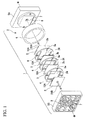
- FIG. 1 is a view illustrating a first embodiment of the bipolar-electrode electrolytic cell according to the invention and is an exploded perspective view of a bipolar-electrode electrolytic cell 1 viewed from one direction.
- the bipolar-electrode electrolytic cell 1 has a plurality of electrode plates 3 and a plurality of spacers 4 inside a chassis 2.
- the chassis 2 includes side plates 5A and 5B, and a body 6. They are formed from a synthetic resin such as vinyl chloride resin, carbonate resin and acrylic resin.
- the side plates 5A and 5B are plate-shaped members which appear to have a rectangular shape with a predetermined thickness. Electrode through holes 7, which pass through the center portion of the side plates 5A and 5B in the thickness direction thereof, respectively, are formed in the side plates 5A and 5B. In addition, at a lower portion of the side plate 5A, a supplying hole 8 for supplying an electrolyte solution which passes through the thickness direction thereof is formed, and at an upper portion of the side plate 5B, an extracting hole 9 for extracting electrolyzed products which passes through the thickness direction thereof is formed.
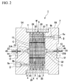
- FIG. 2 is a vertical cross-sectional view of the bipolar-electrode electrolytic cell 1 in an assembled state and illustrates a cross-section in the center of the electrode through hole 7 in FIG. 1 .
- the side plates 5A and 5B have engaging concavities 11 formed on inner surfaces thereof which are opposed, respectively, and have concave portions 12 formed on the center portion of the outer surfaces thereof, respectively.
- the supplying hole 8 includes a large diameter portion 8a and a small diameter portion 8b
- the extracting hole 9 includes a large diameter portion 9a and a small diameter portion 9b.
- the center portion of the inner surface of the side plate 5A has a concavity 13 to fit the electrode plate 3.
- the body 6 is a cylindrical member.
- the side plate 5A is fixed to one end portion of the body 6 and the side plate 5B is fixed to the other end portion thereof.
- the electrode plate 3 is a plate-shaped member made from a metal such as titanium alloy.
- a metal such as titanium alloy.
- coating of platinum for the anode is applied to one plate surface 3a of the electrode plate 3. It is desirable that Coating for the cathode is applied to the other plate surface 3b. However, in the first embodiment, the coating is not applied to the other plate surface 3b.
- the electrode plate 3 is formed in a substantially square shape viewed in a plan view. Furthermore, one end side of an outer periphery of the electrode plate 3 has a cut-out portion 10A of which a shape of the periphery has a substantially U shape.
- the cut-out portion 10A is an engaging portion which is paired with an engaged portion of the spacer 4 described below. If the electrode plate 3 is directed so that the outer periphery having the cut-out portion 10A is positioned on the upper end when the one plate surface 3a of the electrode plate 3 is viewed in a plan view, the cut-out portion 10A is formed to open to the upper side in the right end side of the electrode plate 3.
- Each electrode plate 3, 3 .. is disposed side by side in such a manner that the one plate surface 3a on which the coating is applied is directed in one direction between the side plates 5A and 5B which are disposed facing each other having a predetermined dimensions.
- metal electrode bars 21A and 21B are fixed to center portion of the electrode plate 3 which is disposed on both ends in each electrode plate 3, 3 ⁇ .
- Heads 22 are formed on one end portion in the electrode bars 21A and 21B, and male thread portions 23 are formed on the outer surface of the other end portion. In addition, the Heads 22 are fixed to the center portion of the electrode plate 3.
- the spacer 4 is a plate-shaped member formed from a synthetic resin such as vinyl chloride resin and carbonate resin, and is formed in a circular shape when viewed in a plan view so as to fall into the inside of the cylindrical body 6.
- Each spacer 4, 4 ⁇ is disposed between each electrode plate 3, 3 ⁇ so as to be disposed alternately with each electrode plate 3, 3 ⁇ , and is disposed side by side in such a manner that each one plate surface thereof is directed in one direction between the side plates 5A and 5B.
- the spacer 4 is illustrated in FIGS. 3A to 3C , 4A and 4B .
- the spacer 4 is a circular plate-shaped member and has a hollow hole 24 which passes through the center portion of the plate surface in a direction (in other words, the thickness direction) between the plate surfaces.
- a contour of the hollow hole 24 is a square when viewed in a plan view.
- a dimension of each side configuring the contour of the hollow hole 24 is slightly smaller than the dimension of each side configuring the outer periphery of the electrode plate 3 described above.
- the one plate surface 4a of the spacer 4 has a concavity 25 which is recessed in the thickness direction thereof along an inner wall surface of the hollow hole 24.
- the concavity 25 is formed with a constant width dimension substantially along each side of the hollow hole 24 to be recessed in the thickness direction of the spacer 4, and includes four concave portions 25a to 25d along each side thereof.
- a bottom surface y of one end side of the concave portion 25a has a projecting part 35 protruding in the direction (the thickness direction) between the plate surfaces 4a and 4b of the spacer 4.
- the projecting part 35 is an engaged portion which is formed in a substantially circular column shape.
- FIGS. 5A and 5B when the other plate surface 3b of the electrode plate 3 is opposite to the bottom surface y of the concavity 25, since the cut-out portion 10A of the electrode plate 3 and the projecting part 35 of the spacer 4 are positioned and engaged corresponding to each other, the electrode plate 3 can be disposed inside the concavity 25. As illustrated in FIGS.
- the concavity 25 is provided in the periphery of the projecting part 35 by rounding the circumference thereof so as to bypass the projecting part 35.
- the electrode plate 3 can be fitted inside the concavity 25 of the spacer 4.
- the concavity 25 has a rectangular shape substantially along each side of the hollow hole 24.
- the dimension outside of each side of the rectangular shape is slightly larger than the dimension of each side of the electrode plate 3. Accordingly, the electrode plate 3 is fitted inside the concavity 25 without a clearance and the electrode plate 3 is fixed so as not to move in a direction along the plate surface of the spacer 4.
- the depth of the concavity 25 in the thickness direction is substantially the same dimension as the thickness of the electrode plate 3. Accordingly, when the electrode plate 3 is fitted, the plate surface 3a of the electrode plate 3 and the plate surface 4a of the spacer 4 have the same surface as each other.
- latching portions 26 and 26 are formed on upper and lower portions of the hollow hole 24, and latched portions 27 and 27, which latch the latching portions 26 and 26, are formed on the periphery portion of both sides in the right and left of the hollow hole 24.
- the latching portion 26 and the latched portion 27 make the adjacent spacers 4 and 4 to be coupled with each other.
- Each of the spacers 4 and 4 is connected and coupled by latching the latching portions 26 and 26 of the other spacer 4 to the latched portions 27 and 27 of the one spacer 4 in the spacers 4 and 4 which are adjacent to each other.
- the latched portion 27 is formed on the periphery portion of the spacer 4 and includes a concave portion 27a which is recessed in the hollow hole 24 side of the spacer 4 and in which the latching portion 26 is entered, and a fitting concavity 27b which is recessed in the thickness direction of the spacer 4 in the lateral direction of the outer periphery direction of the concave portion 27a.
- the latching portion 26 is formed on the peripheral portion which is rotated 90 degrees from a position in which the latched portion 27 is formed.
- the latching portion 26 includes a rising wall portion 26a which rises from the plate surface 4a and an extending portion 26b which is bent laterally from the rising wall portion 26a so as to be parallel to the plate surface 4a and along the outer periphery of the spacer 4.
- the thickness of the extending portion 26b is formed of the same dimension as the depth dimension of a recess from the other plate surface 4a of the other spacer 4 to the fitting concavity 27b.
- the plate surface 26c of the extending portion 26b and the plate surface 4a of the other spacer 4 have substantially the same surface as each other.
- lower side of the extending portion 26b is a space portion S.
- a fitting convex portion 36 is formed on the side of circumferential direction of the space portion S which is positioned on the lower side of the extending portion 26b. Meanwhile, a fitting concave portion 37, which is fitted with the fitting convex portion 36 when the latching portion 26 of one spacer 4 is latched on the latched portion 27 of the other spacer 4 which are adjacent to each other, is formed on the side of the fitting concavity 27b of the latched portion 27.
- the latching portion 26 of the spacer 4 of the plurality of spacers 4, 4 ⁇ which is nearest to the side plate 5B, is latched on a latched portion (not illustrated) formed on the side plate 5B.
- the latched portion 27 of the spacer 4, which is nearest to the side plate 5A is latched on a latching portion (not illustrated) formed on the side plate 5A.
- the spacer 4 has liquid through holes 28, 28 ⁇ , through which electrolyte solution passes, formed outside the center portion of the concave portions 25a and 25c which forms the concavity 25 in the right-left direction, and outside of the center portion of the convex portions 25b and 25d in the up-down direction, respectively.
- the liquid through hole 28 is a hole which passes through in the direction between the plate surfaces 4a and 4b (the thickness direction) of the spacer 4.
- a flow passage 30 formed on the plate surface 4b connects between the liquid through hole 28 and the hollow hole 24, and the electrolyte solution introduced in the liquid through hole 28 is guided inside the hollow hole 24 through the flow passage 30 as described below.
- the flow passage 30 is a groove formed on the plate surface 4b.
- the flow passage 30 includes a groove 30a which is straightly extended from the liquid through hole 28 toward the hollow hole 24 and grooves 30b and 30c which are extended from the liquid through hole 28 along the end periphery of the hollow hole 24 in both directions, and which are bent in an intermediate portion thereof and then are extended toward the hollow hole 24.
- the liquid through hole 28, which is positioned on the lower portion of an unit cell C when disposed inside the chassis 2, is an inlet which supplies the electrolyte solution.
- the liquid through hole 28, which is positioned on the upper portion of the unit cell C is an outlet of the electrolyzed products of the electrolyte solution.
- the liquid through holes 28 positioned on the right and left of the unit cell C are liquid-level adjustment holes which communicate with the inside of each unit cell C through the flow passage 30 and adjust a liquid level of the electrolyte solution which invades in the unit cell C.
- the bipolar-electrode electrolytic cell 1 described above is assembled as follows. First, as illustrated in FIG. 5B , the other plate surface 3b on which the coating is not applied is opposite to the bottom surface y of the concavity 25, and the electrode plate 3 is disposed inside the concavity 25 so that the cut-out portion 10A of the electrode plate 3 is directed in the engagement direction with the projecting part 35 of the spacer 4. At this time, as illustrated in FIG.
- the spacer 4 on which the electrode plate 3 is disposed is overlapped and fixed to the other spacer 4 on which the electrode plate 3 is disposed.
- the latching portion 26 of the one spacer 4 enters the concave portion 27a of the latched portion 27 of the other spacer 4.
- a front end of the extending portion 26b of the latching portion 26 is latched on a front end of the fitting concavity 27b of the latched portion 27, and the plate surfaces 4a and 4b of the spacers 4 and 4 which are opposite to each other, are approaching each other.
- the fitting convex portion 36 formed on the plate surface 4a of the one spacer 4 contacts the plate surface 4b of the other spacer 4, and close contact between the plate surfaces 4a and 4b of the spacers 4 and 4 which are linked with each other is prevented.
- the latching portion 26 is elastically deformed to outside the plate surface 4a of the one spacer 4 by the fitting concavity 27b of the latched portion 27.
- the fitting concavity 27b of the latched portion 27 is elastically deformed to outside the plate surface 4b of the other spacer 4 by the latching portion 26.
- a connected body M of the spacers 4, 4 ⁇ is obtained in which the electrode plate 3 illustrated in FIG. 8 is assembled by sequentially connecting the spacers 4 and 4.
- the electrode bar 21A fixed to the electrode plate 3 which is the nearest to the side plate 5A passes through the electrode through hole 7 of the side plate 5A
- the electrode bar 21B fixed to the electrode plate 3 which is the nearest to the side plate 5B passes through the electrode through hole 7 of the side plate 5B.
- the electrode plate 3 which is nearest to the side plate 5B is inserted into the concavity 25 of the spacer 4 positioned one end side of the connected body M, and the body 6 is covered on the connected body M, and the side plate 5A is aligned so that the supplying hole 8 and the liquid through hole 28 communicate with each other.
- the liquid through holes 28 of each spacer 4 communicate with each other.
- the liquid through hole 28 of the liquid through holes 28 communicating with each other which is positioned on the lower side thereof, communicates with the supplying hole 8 of the side plate 5A, and the liquid through hole 28 positioned on the upper side thereof communicates with the extracting hole 9 of the side plate 5B.
- each spacer 4 is covered by two sheets of the adjacent electrode plates 3 and 3 and then a space is formed.
- the inside of the space is the unit cell C in which the electrolyte solution is electrolyzed.
- each spacer 4 is covered by the adjacent spacer 4 and the electrode plate 3 which is fitted into the spacer 4. Accordingly, the flow passage 30 is a fluid passage communicating the liquid through hole 28 and the inside of the hollow hole 24.
- the liquid through hole 28 and the flow passage 30 communicating with the liquid through hole 28 which are positioned on both sides of the right and left of the spacer 4, other than the liquid through holes 28 and 28 communicating with the supplying hole 8 and the extracting hole 9, are covered by the adjacent spacer 4 and the electrode plate 3 fitted into the spacer 4. Accordingly, the flow passage 30 is a fluid passage communicating with the inside of the liquid through hole 28 and the inside of the hollow hole 24. As a result, the insides of the hollow holes 24 of each spacer 4 communicate with each other.
- the electrolyte solution is supplied to the supplying hole 8.
- the electrolyte solution is flowed into the liquid through hole 28 provided on the lower side of each spacer 4 and flowed into the unit cell C through the flow passage 30 of each spacer 4 so that the spacers 4 communicate with each other.
- electricity is applied between the electrode bars so that the electrode bars 21A and 21B are the anode and the cathode, respectively.
- the electrolyte solution is electrolyzed on the one plate surface 3a of the electrode plate 3, and the electrolyzed products of a turbid state of a gas such as chlorine and a liquid inside the unit cell C, or the electrolyzed products which is mainly formed from chlorine or the like, are provided.
- the electrolyzed products reach inside the liquid through hole 28 of the upper side thereof configuring the outlet from the inside of the unit cell C via the flow passage 30 of each spacer 4, and the electrolyzed products are extracted through the extracting hole 9.
- the plate surface 3b of the electrode plate 3 on which the coating is not applied is disposed so as to necessarily oppose the bottom surface y of the concavity 25 of the spacer 4.
- the one plate surface 3a on which the coating is applied for the anode is always the plus side, and normal electrolysis can be performed because chlorine is generated on the plate surface 3a.
- reduction of the electrolysis efficiency of the bipolar-electrode electrolytic cell 1 can be prevented over a long period.
- the electrode plate 3 can be positioned inside the concavity 25.
- the projecting part 35 and the cut-out portion 10A are not positioned at the corresponding positions of each other when the one plate surface 3a of the electrode plate 3 is opposite to the bottom surface y of the concavity 25, the positions thereof are not aligned to each other, and the disposition of the electrode plate 3 inside the concavity 25 is prevented.
- the electrode plate 3 cannot be assembled in the spacer 4 in a direction which is opposite to a predetermined direction. Accordingly, since the front and rear sides of the electrode plate 3 are distinguished each other, the electrode plate 3 is not disposed on the spacer 4 in a wrong direction. Thus, wrong assembly of the electrolytic cell can be prevented so that normal electrolysis can be performed.
- the latching portion 26 and the latched portion 27 are provided, and the fitting convex portion 36 and the fitting concave portion 37 are formed on the spacer 4.
- the connection of the spacers 4 and 4 between each other can be performed simply, and the connection state can be made firm.
- the cut-out portion 10A is formed so that the shape of the peripheral portion is in substantially a U shape.
- the invention is not limited to the embodiment.
- the shape of the peripheral portion of the cut-out portion 10A may be formed so as to be substantially a V shape, and may be formed in other polygonal.
- the cut-out portion 10A surrounds the outer periphery of the projecting part 35, and may be open to the outside of one end periphery of the electrode plate 3.
- the projecting part 35 is not necessarily formed on the right end portion of the concave portion 25a which is positioned on the upper portion side of the concavity 25 of the spacer 4. If the projecting part 35 is not formed on imaginary center lines L1 to L4 (in other words, lines bisecting the outer periphery of the concavity 25 so as to be the line symmetry) passing points p and p which bisect corner portions 25s and 25s of the concavity 25 or one side of the concavity 25, the projecting part 35 may form on any position of the concavity 25.
- imaginary center lines L1 to L4 in other words, lines bisecting the outer periphery of the concavity 25 so as to be the line symmetry
- the electrode plate 3 can be disposed on the concavity 25, because the electrode plate 3 having the cut-out portion 10A, which is fitted into the projecting part 35, is positioned such that the projecting part 35 and the cut-out portion 10A correspond to each other even though any one of the plate surfaces 3a and 3b is directed to the spacer 4.
- the projecting part 35 is formed on a position which is shifted from the imaginary center lines L1 to L4 and the cut-out portion 10A of the electrode plate 3 is formed so as to surround the projecting part 35, the forming position of the cut-out portion 10A when the one plate surface 3a of the electrode plate 3 is viewed in a plan view, and the forming position of the cut-out portion 10A when the other plate surface 3b is viewed in a front view, are not always aligned to each other.
- the one plate surface 3a of the electrode plate 3 can be always disposed in one direction on the spacer 4.
- FIGS. 10A to 10D a second embodiment of the invention will be described referring to FIGS. 10A to 10D .
- the same reference numeral is given to the same configuration of the first embodiment and the description thereof will be omitted.
- a shape of a cut-out portion 10B of the electrode plate 3 is different from the first embodiment.
- the configuration of the second embodiment is the same as the first embodiment.
- the cut-out portion 10B of the second embodiment is formed such that an angle portion 3s of the electrode plate 3 corresponding to the projecting part 35 of the spacer 4 is cut in a straight shape when the one plate surface 3 a of the electrode plate 3 is viewed from a front view.
- Two angles ⁇ 1 and ⁇ 2 formed on the electrode plate 3 are formed to be different from each other by the cutting.
- the shapes of the electrode plates 3 are different from each other by such an electrode plate 3, between a case where the one plate surface 3a of the electrode plate 3 is directed in one direction and a case where the other plate surface 3b of the electrode plate 3 is directed in one direction.
- the electrode plate 3 can be disposed on the spacer 4. Accordingly, the same functions and effects as those of the above first embodiment can be obtained.
- FIGS. 11A to 11D a third embodiment of the invention will be described referring to FIGS. 11A to 11D .
- the same reference numeral is given to the same configuration of the first embodiment and the description thereof will be omitted.
- the configuration thereof is different from the first embodiment in that the engaging portion is not cut out and is a hole 40 into which the projecting part 35 is fitted. Besides that, the configuration thereof is similar to the first embodiment.
- the hole 40 has a diameter slightly larger than the diameter of the circle column of the projecting part 35, and the projecting part 35 can be fitted into the hole 40.
- the projecting part 35 is formed so as not to position on the imaginary center lines L1 to L4. Furthermore, when the other plate surface 3b is disposed opposite to the bottom surface y of the concavity 25 of the spacer 4, the hole 40 of the electrode plate 3 is formed on a position into which the projecting part 35 is fitted. Accordingly, in the case described above, the projecting part 35 is fitted into the hole 40, and the electrode plate 3 can be disposed on the concavity 25. However, as illustrated in FIGS.
- the engaged portion is the projecting part 35 and any of the electrode plate 3 having the cut-out portion 10A or the electrode plate 3 having the cut-out portion 10B can be applied to the spacer 4 including the projecting part 35.
- the latched portion may be a projecting wall 50 or 51 fitted into the cut-out portion 10A or 10B, instead of the projecting part 35. Even in a case when the engaged portion is the projecting wall 50 or 51, only when the electrode plate 3 is directed in one direction, the electrode plate 3 can be disposed on the concavity 25.
- the same functions and effects as those of the above first and second embodiments can be obtained.
- the bipolar-electrode electrolytic cell of the invention corrosion of the electrode plate can be avoid due to an wrong disposition of the electrode plate, and decrease of the electrolysis efficiency of the bipolar-electrode electrolytic cell in the early stage can be avoid.
- peeling of the coating of the electrode plate can be avoided, and the short life of the electrode plate is prevented.
- the electrolysis efficiency of the bipolar-electrode electrolytic cell can be maintained for a long period.
Landscapes
- Chemical & Material Sciences (AREA)
- Engineering & Computer Science (AREA)
- Chemical Kinetics & Catalysis (AREA)
- Electrochemistry (AREA)
- Organic Chemistry (AREA)
- Materials Engineering (AREA)
- Metallurgy (AREA)
- Life Sciences & Earth Sciences (AREA)
- General Chemical & Material Sciences (AREA)
- Hydrology & Water Resources (AREA)
- Environmental & Geological Engineering (AREA)
- Water Supply & Treatment (AREA)
- Inorganic Chemistry (AREA)
- Water Treatment By Electricity Or Magnetism (AREA)
- Electrolytic Production Of Non-Metals, Compounds, Apparatuses Therefor (AREA)
- Connection Of Batteries Or Terminals (AREA)
- Secondary Cells (AREA)
- Electrolytic Production Of Metals (AREA)
Abstract
Description
- The present invention relates to a bipolar-electrode electrolytic cell included in an electrolysis water-making apparatus which generates electrolysis sterilized water. Priority is claimed on Japanese Patent Application No.
2011-072048, filed March 29, 2011 - In the related art, in order to generate electrolysis sterilized water which sterilizes and cleans food or an apparatus for manufacturing food in a food manufacturing field or the like, an electrolytic water manufacturing apparatus including a bipolar-electrode electrolytic cell is used (for example, Patent Document 1). In the bipolar-electrode electrolytic cell, a large number of electrode plates formed from titanium oxide or the like are arranged, insulation spacers are respectively disposed between the electrode plates so as not to short-circuit the adjacent electrode plates, and unit cells are independently formed and respectively between the electrode plates. A catalyst coated on a base material of the electrode plate of the electrolytic cell is formed from noble metals such as platinum (Pt) or iridium (Ir), which are expensive. Thus, the cost can be reduced by coating the catalyst thin on a surface of titanium metal which is relatively inexpensive and has excellent strength, workability and corrosion resistance. In addition, since the generated materials are different from each other in a cathode and an anode, different catalysts may be used. Usually, the electrode plate of hydrochloric acid electrolysis which is obtained by coating, the catalyst such as Pr or Ir on the base material formed of titanium is used. Specifically, Pt or Ir is essential to generate chlorine gas on an anode surface and the life of the electrode is increased in proportion to the coated amount. Meanwhile, Pt or Ir is not essential to generate hydrogen gas on the cathode surface and the catalyst different from the anode surface may be coated. In addition, in a case where the base material is formed of titanium, hydrogen gas may be generated even though the coating of the catalyst is not present. Thus, coating only one surface of the electrode plate is coated can be used so that the simplest electrode in which both cathode and anode surfaces are present on the front and rear of one electrode plate is provided. Accordingly, in the assembly of the bipolar-electrode electrolytic cell, one plate surface on which platinum, iridium oxide or the like is coated, is directed to be a plus side, and then the electrode plate and the spacer are disposed. In other words, chloride is generated on the one plate surface and hydrogen is generated on the other plate surface.
- [Patent Document 1] Japanese Unexamined Patent Application, First Publication No.
2010-058052 - However, according to a bipolar-electrode electrolytic cell of the related art described above, an electrode plate is disposed on a spacer by observing the front and rear of a plate surface of the electrode plate and by determining the direction of the plate surface. Thus, the electrolytic cell may be assembled in which normal electrolysis cannot be performed by disposing the electrode plate on the spacer in a wrong direction.
- In addition, the wrong disposition of the electrode plate described above leads to reduce electrolysis efficiency of the bipolar-electrode electrolytic cell in the early stage.
- In addition, in order to prevent the wrong disposition of the electrode plate described above, it is necessary to dispose the electrode plate after sufficiently checking the front and rear of the electrode plate. Thus, the efficiency of assembly work of the bipolar-electrode electrolytic cell is reduced due to the determination of the front and rear of the plate surface of the electrode plate.
- The invention has been accomplished in considering the above described problems and provides a bipolar-electrode electrolytic cell in which a direction of an electrode plate to a spacer is easily determined, wrong assembly of the bipolar-electrode electrolytic cell can be prevented easily and reliably, and reduction of an electrolysis efficiency in the early stage can be prevented.
- The invention provides following means to solve the above problems. That is, a bipolar-electrode electrolytic cell according to a first invention of the present application includes a chassis; an electrode plate performing electrolysis in electrolyte solution and generating electrolyzed products; and a plate-shaped spacer having a concavity on which the electrode plate is disposed in which a unit cell, which is formed by connecting a plurality of spacers in which the electrode plate is disposed on the concavity so that one plate surface of the electrode plate is directed to one direction, is disposed inside the chassis. In addition, the bipolar-electrode electrolytic cell includes an engaged portion which is provided on any one side of the concavity of the spacer and the electrode plate; and an engaging portion which is formed on the other portion with respect to the one side portion. The engaged portion and the engaging portion are positioned so as to correspond to each other, and are formed to dispose the electrode plate inside the concavity, when the one plate surface of the electrode plate is disposed on the concavity toward the one direction. Furthermore, the engaged portion and the engaging portion are positioned so as not to correspond to each other, and are prevented from disposing the electrode plate inside the concavity, when the other plate surface of the electrode plate is disposed on the concavity toward the one direction.
- In bipolar-electrode electrolytic cell of a second invention of the application according to the first invention, the engaged portion is a projecting wall or a projecting part formed on the concavity, and
wherein the engaging portion is a cut-out portion or a hole formed on the electrode plate. - In bipolar-electrode electrolytic cell of a third invention of the application according to the first or second invention, the spacer has a latching portion formed on the plate surface and a latched portion which latches the latching portion of another spacer and performs connection thereto.
- In bipolar-electrode electrolytic cell of a fourth invention of the application according to the third invention, a fitting convex portion is formed on the one plate surface of the spacer and a fitting concave portion, which is fitted into the fitting convex portion of the one plate surface of the other spacer and holds the connection between spacers, is formed on the other plate surface of the spacer.
- According to the bipolar-electrode electrolytic cell of the invention, the engaged portion and the engaging portion are formed on the electrode plate and the spacer, respectively so that the engaged portion and the engaging portion are positioned to correspond to each other and can dispose the electrode plate inside the concavity, when one plate surface of the electrode plate is disposed on the concavity toward one direction. Meanwhile, the engaged portion and the engaging portion are formed on the electrode plate and the spacer, respectively so that the engaged portion and the engaging portion are positioned so as not to correspond to each other and are prevented from disposing the electrode plate inside the concavity, when the other plate surface of the electrode plate is disposed on the concavity toward one direction. In other words, the electrode plate cannot be assembled to the spacer other than a predetermined direction of the electrode plate. Accordingly, when the front and rear of the electrode plate is provided in distinguished way, the electric plate does not get disposed in a wrong direction. Accordingly, corrosion of the electrode plate can be avoided due to a wrong disposition of the electrode plate, and reduction of the electrolysis efficiency of the bipolar-electrode electrolytic cell in the early stage can be avoided. In addition, peeling of the coating of the electrode plate can be avoided, and the short life of the electrode plate is prevented.
- In addition, according to the bipolar-electrode electrolytic cell of the invention, the electrolysis efficiency of the bipolar-electrode electrolytic cell can be maintained for a long period.
- In addition, according to the bipolar-electrode electrolytic cell of the invention, since determination of the direction of the electrode plate is easily performed, the assembly of the bipolar-electrode electrolytic cell can be performed simply and efficiently.
-
-
FIG. 1 is a view illustrating a bipolar-electrode electrolytic cell illustrated as a first embodiment of the invention, and is an exploded perspective view of the bipolar-electrode electrolytic cell viewed from one direction. -
FIG. 2 is a vertical cross-sectional view of the bipolar-electrode electrolytic cell illustrated as the first embodiment of the invention. -
FIG. 3A is a view illustrating a spacer of the bipolar-electrode electrolytic cell illustrated as the first embodiment of the invention, and is a front view of the spacer. -
FIG. 3B is a view illustrating the spacer of the bipolar-electrode electrolytic cell illustrated as the first embodiment of the invention, and is a side view of the spacer. -
FIG. 3C is a view illustrating the spacer of the bipolar-electrode electrolytic cell illustrated as the first embodiment of the invention, and is a rear view of the spacer. -
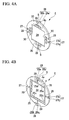
FIG. 4A is a view illustrating the spacer of the bipolar-electrode electrolytic cell illustrated as the first embodiment of the invention, and is a perspective view of the spacer viewed from in a rear direction. -
FIG. 4B is a view illustrating the spacer of the bipolar-electrode electrolytic cell illustrated as the first embodiment of the invention, and is a perspective view of the spacer viewed from in a front direction. -
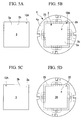
FIG. 5A is a view illustrating an electrode plate of the bipolar-electrode electrolytic cell illustrated as the first embodiment of the invention, and is a front view of the electrode plate. -
FIG. 5B is a view illustrating the spacer of the bipolar-electrode electrolytic cell illustrated as the first embodiment of the invention, and is a front view of the spacer into which the electrode plate illustrated inFIG. 5A is fitted. -
FIG. 5C is a view illustrating the electrode plate of the bipolar-electrode electrolytic cell illustrated as the first embodiment of the invention, and is a rear view of the electrode plate. -
FIG. 5D is a view illustrating the spacer of the bipolar-electrode electrolytic cell illustrated as the first embodiment of the invention, and is a front view of the spacer. -
FIG. 6 is an enlarged perspective view illustrating a connection state between the spacers of the bipolar-electrode electrolytic cell illustrated as the first embodiment of the invention. -
FIG. 7 is an explanatory view illustrating a connection method of the electrode plate and the spacer of the bipolar-electrode electrolytic cell illustrated as the first embodiment of the invention. -
FIG. 8 is a perspective view illustrating a connected state of the electrode plate and the spacer of the bipolar-electrode electrolytic cell illustrated as the first embodiment of the invention. -
FIG. 9A is a view illustrating a modification example of the electrode plate of the bipolar-electrode electrolytic cell illustrated as the first embodiment of the invention, and is a front view of the electrode plate. -
FIG. 9B is a view illustrating a modification example of the spacer of the bipolar-electrode electrolytic cell illustrated as the first embodiment of the invention, and is a front view of the spacer into which the electrode plate is illustrated inFIG. 9A . -
FIG. 10A is a view illustrating the electrode plate of the bipolar-electrode electrolytic cell illustrated as a second embodiment of the invention, and is a front view of the electrode plate. -
FIG. 10B is a view illustrating the spacer of the bipolar-electrode electrolytic cell illustrated as the second embodiment of the invention, and is a front view of the spacer into which the electrode plate is fitted illustrated inFIG. 10A . -
FIG. 10C is a view illustrating the electrode plate of the bipolar-electrode electrolytic cell illustrated as the second embodiment of the invention, and is a rear view of the electrode plate. -
FIG. 10D is a view illustrating the spacer of the bipolar-electrode electrolytic cell illustrated as the second embodiment of the invention, and is a front view of the spacer. -
FIG. 11A is a view illustrating the electrode plate of the bipolar-electrode electrolytic cell illustrated as a third embodiment of the invention, and is a front view of the electrode plate. -
FIG. 11B is a view illustrating the spacer of the bipolar-electrode electrolytic cell illustrated as the third embodiment of the invention, and is a front view of the spacer fitted into the electrode plate illustrated inFIG. 11A . -
FIG. 11C is a view illustrating the electrode plate of the bipolar-electrode electrolytic cell illustrated as the third embodiment of the invention, and is a rear view of the electrode plate. -
FIG. 11D is a view illustrating the spacer of the bipolar-electrode electrolytic cell illustrated as the third embodiment of the invention and is a front view of the spacer. -
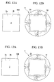
FIG. 12A is a view illustrating a modification example of the electrode plate of the bipolar-electrode electrolytic cell illustrated as the first embodiment of the invention, and is a front view of the electrode plate. -
FIG. 12B is a view illustrating a modification example of the spacer of the bipolar-electrode electrolytic cell illustrated as the first embodiment of the invention, and is a front view of the spacer into which the electrode plate is fitted illustrated inFIG. 12A . -
FIG. 13A is a view illustrating a modification example of the electrode plate of the bipolar-electrode electrolytic cell illustrated as the second embodiment of the invention, and is a front view of the electrode plate. -
FIG. 13B is a view illustrating a modification example of the spacer of the bipolar-electrode electrolytic cell illustrated as the second embodiment of the invention, and is a front view of the spacer into which the electrode plate is fitted illustrated inFIG. 13A . - Hereinafter, an embodiment of a bipolar-electrode electrolytic cell of the invention will be described referring to the drawings.
-
FIG. 1 is a view illustrating a first embodiment of the bipolar-electrode electrolytic cell according to the invention and is an exploded perspective view of a bipolar-electrode electrolytic cell 1 viewed from one direction. As illustrated inFIG. 1 , the bipolar-electrode electrolytic cell 1 has a plurality ofelectrode plates 3 and a plurality ofspacers 4 inside achassis 2. - The
chassis 2 includesside plates body 6. They are formed from a synthetic resin such as vinyl chloride resin, carbonate resin and acrylic resin. - The
side plates holes 7, which pass through the center portion of theside plates side plates side plate 5A, a supplyinghole 8 for supplying an electrolyte solution which passes through the thickness direction thereof is formed, and at an upper portion of theside plate 5B, an extractinghole 9 for extracting electrolyzed products which passes through the thickness direction thereof is formed. -
FIG. 2 is a vertical cross-sectional view of the bipolar-electrode electrolytic cell 1 in an assembled state and illustrates a cross-section in the center of the electrode throughhole 7 inFIG. 1 . As illustrated inFIG. 2 , theside plates concavities 11 formed on inner surfaces thereof which are opposed, respectively, and haveconcave portions 12 formed on the center portion of the outer surfaces thereof, respectively. In addition, the supplyinghole 8 includes alarge diameter portion 8a and asmall diameter portion 8b, and the extractinghole 9 includes alarge diameter portion 9a and asmall diameter portion 9b. In addition, the center portion of the inner surface of theside plate 5A has aconcavity 13 to fit theelectrode plate 3. - The
body 6 is a cylindrical member. Theside plate 5A is fixed to one end portion of thebody 6 and theside plate 5B is fixed to the other end portion thereof. - The
electrode plate 3 is a plate-shaped member made from a metal such as titanium alloy. For example, coating of platinum for the anode is applied to oneplate surface 3a of theelectrode plate 3. It is desirable that Coating for the cathode is applied to theother plate surface 3b. However, in the first embodiment, the coating is not applied to theother plate surface 3b. - In addition, as illustrated in
FIG. 1 , theelectrode plate 3 is formed in a substantially square shape viewed in a plan view. Furthermore, one end side of an outer periphery of theelectrode plate 3 has a cut-outportion 10A of which a shape of the periphery has a substantially U shape. - The cut-out
portion 10A is an engaging portion which is paired with an engaged portion of thespacer 4 described below. If theelectrode plate 3 is directed so that the outer periphery having the cut-outportion 10A is positioned on the upper end when the oneplate surface 3a of theelectrode plate 3 is viewed in a plan view, the cut-outportion 10A is formed to open to the upper side in the right end side of theelectrode plate 3. - Each
electrode plate plate surface 3a on which the coating is applied is directed in one direction between theside plates FIG. 2 ,metal electrode bars electrode plate 3 which is disposed on both ends in eachelectrode plate -
Heads 22 are formed on one end portion in the electrode bars 21A and 21B, andmale thread portions 23 are formed on the outer surface of the other end portion. In addition, theHeads 22 are fixed to the center portion of theelectrode plate 3. - As illustrated in
FIG. 1 , thespacer 4 is a plate-shaped member formed from a synthetic resin such as vinyl chloride resin and carbonate resin, and is formed in a circular shape when viewed in a plan view so as to fall into the inside of thecylindrical body 6. Eachspacer electrode plate electrode plate side plates - The
spacer 4 is illustrated inFIGS. 3A to 3C ,4A and 4B . As illustrated in the figures, thespacer 4 is a circular plate-shaped member and has ahollow hole 24 which passes through the center portion of the plate surface in a direction (in other words, the thickness direction) between the plate surfaces. A contour of thehollow hole 24 is a square when viewed in a plan view. In addition, a dimension of each side configuring the contour of thehollow hole 24 is slightly smaller than the dimension of each side configuring the outer periphery of theelectrode plate 3 described above. - The one
plate surface 4a of thespacer 4 has aconcavity 25 which is recessed in the thickness direction thereof along an inner wall surface of thehollow hole 24. In other words, theconcavity 25 is formed with a constant width dimension substantially along each side of thehollow hole 24 to be recessed in the thickness direction of thespacer 4, and includes fourconcave portions 25a to 25d along each side thereof. - A bottom surface y of one end side of the
concave portion 25a has a projectingpart 35 protruding in the direction (the thickness direction) between the plate surfaces 4a and 4b of thespacer 4. As illustrated inFIG. 4B , the projectingpart 35 is an engaged portion which is formed in a substantially circular column shape. As illustrated inFIGS. 5A and 5B , when theother plate surface 3b of theelectrode plate 3 is opposite to the bottom surface y of theconcavity 25, since the cut-outportion 10A of theelectrode plate 3 and the projectingpart 35 of thespacer 4 are positioned and engaged corresponding to each other, theelectrode plate 3 can be disposed inside theconcavity 25. As illustrated inFIGS. 10C and 10D , when the coated oneplate surface 3a is opposite to the bottom surface y of theconcavity 25, the cut-outportion 10A of theelectrode plate 3 and the projectingpart 35 of thespacer 4 are not positioned corresponding to each other. In other words, since the engagement position (the engagement position of the cut-outportion 10A and the projectingpart 35 each other) of theelectrode plate 3 and thespacer 4 do not fit each other, disposition of theelectrode plate 3 inside theconcavity 25 is prevented. - In other words, when the
other plate surface 3b of theelectrode plate 3 is opposite to the bottom surface y of the concavity 25 (in a case ofFIG. 5A ), since the positions of the projectingpart 35 of thespacer 4 and the cut-outportion 10A of theelectrode plate 3 illustrated inFIG. 5B correspond to each other, both can be engaged. Meanwhile, when theelectrode plate 3 illustrated inFIG. 5A is turned over and directed as illustrated inFIG. 10C , since the positions of the projectingpart 35 and the cut-outportion 10A are not aligned with each other even though theother plate surface 3b is rotated to a certain angle, theelectrode plate 3 contacts the projectingpart 35 and theelectrode plate 3 cannot be disposed inside theconcavity 25. - The
concavity 25 is provided in the periphery of the projectingpart 35 by rounding the circumference thereof so as to bypass the projectingpart 35. - As described above and as illustrated in
FIGS. 5A and 5B , only when theelectrode plate 3 is directed in one direction, theelectrode plate 3 can be fitted inside theconcavity 25 of thespacer 4. - In addition, the
concavity 25 has a rectangular shape substantially along each side of thehollow hole 24. The dimension outside of each side of the rectangular shape is slightly larger than the dimension of each side of theelectrode plate 3. Accordingly, theelectrode plate 3 is fitted inside theconcavity 25 without a clearance and theelectrode plate 3 is fixed so as not to move in a direction along the plate surface of thespacer 4. In addition, the depth of theconcavity 25 in the thickness direction is substantially the same dimension as the thickness of theelectrode plate 3. Accordingly, when theelectrode plate 3 is fitted, theplate surface 3a of theelectrode plate 3 and theplate surface 4a of thespacer 4 have the same surface as each other. - As illustrated in
FIGS. 4A and 4B , in thespacer 4, latchingportions hollow hole 24, and latchedportions portions hollow hole 24. As illustrated inFIG. 6 , the latchingportion 26 and the latchedportion 27 make theadjacent spacers spacers portions other spacer 4 to the latchedportions spacer 4 in thespacers - As illustrated in
FIGS. 4A and 4B , the latchedportion 27 is formed on the periphery portion of thespacer 4 and includes aconcave portion 27a which is recessed in thehollow hole 24 side of thespacer 4 and in which the latchingportion 26 is entered, and afitting concavity 27b which is recessed in the thickness direction of thespacer 4 in the lateral direction of the outer periphery direction of theconcave portion 27a. - The latching
portion 26 is formed on the peripheral portion which is rotated 90 degrees from a position in which the latchedportion 27 is formed. The latchingportion 26 includes a risingwall portion 26a which rises from theplate surface 4a and an extendingportion 26b which is bent laterally from the risingwall portion 26a so as to be parallel to theplate surface 4a and along the outer periphery of thespacer 4. - As illustrated in
FIG. 6 , the thickness of the extendingportion 26b is formed of the same dimension as the depth dimension of a recess from theother plate surface 4a of theother spacer 4 to thefitting concavity 27b. When the extendingportion 26b of the latchingportion 26 is overlapped and latched on thefitting concavity 27b of the latchedportion 27, theplate surface 26c of the extendingportion 26b and theplate surface 4a of theother spacer 4 have substantially the same surface as each other. In addition, lower side of the extendingportion 26b is a space portion S. - A fitting
convex portion 36 is formed on the side of circumferential direction of the space portion S which is positioned on the lower side of the extendingportion 26b. Meanwhile, a fittingconcave portion 37, which is fitted with the fittingconvex portion 36 when the latchingportion 26 of onespacer 4 is latched on the latchedportion 27 of theother spacer 4 which are adjacent to each other, is formed on the side of thefitting concavity 27b of the latchedportion 27. - In addition, the latching
portion 26 of thespacer 4 of the plurality ofspacers side plate 5B, is latched on a latched portion (not illustrated) formed on theside plate 5B. Meanwhile, the latchedportion 27 of thespacer 4, which is nearest to theside plate 5A, is latched on a latching portion (not illustrated) formed on theside plate 5A. - In addition, as illustrated in
FIG. 4B , thespacer 4 has liquid throughholes concave portions concavity 25 in the right-left direction, and outside of the center portion of theconvex portions - The liquid through
hole 28 is a hole which passes through in the direction between the plate surfaces 4a and 4b (the thickness direction) of thespacer 4. Aflow passage 30 formed on theplate surface 4b connects between the liquid throughhole 28 and thehollow hole 24, and the electrolyte solution introduced in the liquid throughhole 28 is guided inside thehollow hole 24 through theflow passage 30 as described below. - As illustrated in
FIG. 4A , theflow passage 30 is a groove formed on theplate surface 4b. As illustrated inFIG. 3C , theflow passage 30 includes agroove 30a which is straightly extended from the liquid throughhole 28 toward thehollow hole 24 andgrooves hole 28 along the end periphery of thehollow hole 24 in both directions, and which are bent in an intermediate portion thereof and then are extended toward thehollow hole 24. - In addition, as illustrated in
FIG. 2 , the liquid throughhole 28, which is positioned on the lower portion of an unit cell C when disposed inside thechassis 2, is an inlet which supplies the electrolyte solution. In addition, the liquid throughhole 28, which is positioned on the upper portion of the unit cell C is an outlet of the electrolyzed products of the electrolyte solution. Furthermore, the liquid throughholes 28 positioned on the right and left of the unit cell C are liquid-level adjustment holes which communicate with the inside of each unit cell C through theflow passage 30 and adjust a liquid level of the electrolyte solution which invades in the unit cell C. - The bipolar-electrode electrolytic cell 1 described above is assembled as follows. First, as illustrated in
FIG. 5B , theother plate surface 3b on which the coating is not applied is opposite to the bottom surface y of theconcavity 25, and theelectrode plate 3 is disposed inside theconcavity 25 so that the cut-outportion 10A of theelectrode plate 3 is directed in the engagement direction with the projectingpart 35 of thespacer 4. At this time, as illustrated inFIG. 5C , when the direction of theelectrode plate 3 is opposite to the direction described above, in other words, when the oneplate surface 3a on which the coating is applied is disposed to be opposite to the bottom surface y of theconcavity 25, since the positions of the cut-outportion 10A and the projectingpart 35 are not aligned with each other, the disposition of theelectrode plate 3 on theconcavity 25 is prevented by the projectingpart 35. - Then, as illustrated in
FIG. 7 , thespacer 4 on which theelectrode plate 3 is disposed is overlapped and fixed to theother spacer 4 on which theelectrode plate 3 is disposed. In other words, the latchingportion 26 of the onespacer 4 enters theconcave portion 27a of the latchedportion 27 of theother spacer 4. Therewith, a front end of the extendingportion 26b of the latchingportion 26 is latched on a front end of thefitting concavity 27b of the latchedportion 27, and the plate surfaces 4a and 4b of thespacers convex portion 36 formed on theplate surface 4a of the onespacer 4 contacts theplate surface 4b of theother spacer 4, and close contact between the plate surfaces 4a and 4b of thespacers portion 26 is elastically deformed to outside theplate surface 4a of the onespacer 4 by thefitting concavity 27b of the latchedportion 27. In addition, thefitting concavity 27b of the latchedportion 27 is elastically deformed to outside theplate surface 4b of theother spacer 4 by the latchingportion 26. - In this state, when the one
spacer 4 is slid so as to relatively move to theother spacer 4, the fittingconvex portion 36 fits with the fittingconcave portion 37. Accordingly, plate surfaces 4a and 4b of thespacers portion 26b and thefitting concavity 27b contact. As a result, thespacers electrode plate 3 is covered byadjacent spacer 4. Thus, eachelectrode plate 3 is held so as not to move inside theconcavity 25 of thespacer 4 into which eachelectrode plate 3 is fitted. - As described above, a connected body M of the
spacers electrode plate 3 illustrated inFIG. 8 is assembled by sequentially connecting thespacers - Then, as illustrated in
FIG. 2 , theelectrode bar 21A fixed to theelectrode plate 3 which is the nearest to theside plate 5A passes through the electrode throughhole 7 of theside plate 5A, and theelectrode bar 21B fixed to theelectrode plate 3 which is the nearest to theside plate 5B passes through the electrode throughhole 7 of theside plate 5B. Then, theelectrode plate 3 which is nearest to theside plate 5B is inserted into theconcavity 25 of thespacer 4 positioned one end side of the connected body M, and thebody 6 is covered on the connected body M, and theside plate 5A is aligned so that the supplyinghole 8 and the liquid throughhole 28 communicate with each other. Then, in a state where awasher 43 and aspring washer 44 are interposed on themale thread portion 23 of each of electrode bars 21 A and 21 B, anut 45 is fastened. Accordingly, theside plate 5A, thebody 6, theside plate 5B, and thespacers electrode plate 3 which is nearest to theside plate 5A is fitted inside theconcavity 13 of theside plate 5A. - In the above configuration, the liquid through
holes 28 of eachspacer 4 communicate with each other. In addition, the liquid throughhole 28 of the liquid throughholes 28 communicating with each other, which is positioned on the lower side thereof, communicates with the supplyinghole 8 of theside plate 5A, and the liquid throughhole 28 positioned on the upper side thereof communicates with the extractinghole 9 of theside plate 5B. - In addition, the
hollow hole 24 of eachspacer 4 is covered by two sheets of theadjacent electrode plates - In addition, the
flow passage 30 of eachspacer 4 is covered by theadjacent spacer 4 and theelectrode plate 3 which is fitted into thespacer 4. Accordingly, theflow passage 30 is a fluid passage communicating the liquid throughhole 28 and the inside of thehollow hole 24. - In addition, the liquid through
hole 28 and theflow passage 30 communicating with the liquid throughhole 28 which are positioned on both sides of the right and left of thespacer 4, other than the liquid throughholes hole 8 and the extractinghole 9, are covered by theadjacent spacer 4 and theelectrode plate 3 fitted into thespacer 4. Accordingly, theflow passage 30 is a fluid passage communicating with the inside of the liquid throughhole 28 and the inside of thehollow hole 24. As a result, the insides of thehollow holes 24 of eachspacer 4 communicate with each other. - Next, production of the electrolyzed products in the bipolar-electrode electrolytic cell 1 described above will be described referring to
FIG. 2 . First, the electrolyte solution is supplied to the supplyinghole 8. The electrolyte solution is flowed into the liquid throughhole 28 provided on the lower side of eachspacer 4 and flowed into the unit cell C through theflow passage 30 of eachspacer 4 so that thespacers 4 communicate with each other. When the electrolyte solution reaches a predetermined amount inside the unit cell C, electricity is applied between the electrode bars so that the electrode bars 21A and 21B are the anode and the cathode, respectively. As a result, the electrolyte solution is electrolyzed on the oneplate surface 3a of theelectrode plate 3, and the electrolyzed products of a turbid state of a gas such as chlorine and a liquid inside the unit cell C, or the electrolyzed products which is mainly formed from chlorine or the like, are provided. The electrolyzed products reach inside the liquid throughhole 28 of the upper side thereof configuring the outlet from the inside of the unit cell C via theflow passage 30 of eachspacer 4, and the electrolyzed products are extracted through the extractinghole 9. - In this case, as described above, the
plate surface 3b of theelectrode plate 3 on which the coating is not applied is disposed so as to necessarily oppose the bottom surface y of theconcavity 25 of thespacer 4. In other words, when the electricity is applied between the electrode bars 21A and 21B as described above, the oneplate surface 3a on which the coating is applied for the anode is always the plus side, and normal electrolysis can be performed because chlorine is generated on theplate surface 3a. In addition, reduction of the electrolysis efficiency of the bipolar-electrode electrolytic cell 1 can be prevented over a long period. - As described above, according to the bipolar-electrode electrolytic cell 1, since the projecting
part 35 and the cut-outportion 10A are positioned at the corresponding positions each other when theother plate surface 3b of theelectrode plate 3 is opposite to the bottom surface y of theconcavity 25, theelectrode plate 3 can be positioned inside theconcavity 25. On the other hand, since the projectingpart 35 and the cut-outportion 10A are not positioned at the corresponding positions of each other when the oneplate surface 3a of theelectrode plate 3 is opposite to the bottom surface y of theconcavity 25, the positions thereof are not aligned to each other, and the disposition of theelectrode plate 3 inside theconcavity 25 is prevented. In other words, theelectrode plate 3 cannot be assembled in thespacer 4 in a direction which is opposite to a predetermined direction. Accordingly, since the front and rear sides of theelectrode plate 3 are distinguished each other, theelectrode plate 3 is not disposed on thespacer 4 in a wrong direction. Thus, wrong assembly of the electrolytic cell can be prevented so that normal electrolysis can be performed. - In addition, since determination of the direction of the
electrode plate 3 is easily performed, the assembly of the bipolar-electrode electrolytic cell 1 can be performed simply and efficiently. - In addition, in the first embodiment, the latching
portion 26 and the latchedportion 27 are provided, and the fittingconvex portion 36 and the fittingconcave portion 37 are formed on thespacer 4. Thus, the connection of thespacers - In addition, in the first embodiment, the cut-out
portion 10A is formed so that the shape of the peripheral portion is in substantially a U shape. However, the invention is not limited to the embodiment. For example, as illustrated inFIGS. 9A and 9B , the shape of the peripheral portion of the cut-outportion 10A may be formed so as to be substantially a V shape, and may be formed in other polygonal. In brief, the cut-outportion 10A surrounds the outer periphery of the projectingpart 35, and may be open to the outside of one end periphery of theelectrode plate 3. - In addition, the projecting
part 35 is not necessarily formed on the right end portion of theconcave portion 25a which is positioned on the upper portion side of theconcavity 25 of thespacer 4. If the projectingpart 35 is not formed on imaginary center lines L1 to L4 (in other words, lines bisecting the outer periphery of theconcavity 25 so as to be the line symmetry) passing points p and p which bisectcorner portions concavity 25 or one side of theconcavity 25, the projectingpart 35 may form on any position of theconcavity 25. - In other words, if the projecting
part 35 is formed on the imaginary center lines L1 to L4, theelectrode plate 3 can be disposed on theconcavity 25, because theelectrode plate 3 having the cut-outportion 10A, which is fitted into the projectingpart 35, is positioned such that the projectingpart 35 and the cut-outportion 10A correspond to each other even though any one of the plate surfaces 3a and 3b is directed to thespacer 4. On the other hand, when the projectingpart 35 is formed on a position which is shifted from the imaginary center lines L1 to L4 and the cut-outportion 10A of theelectrode plate 3 is formed so as to surround the projectingpart 35, the forming position of the cut-outportion 10A when the oneplate surface 3a of theelectrode plate 3 is viewed in a plan view, and the forming position of the cut-outportion 10A when theother plate surface 3b is viewed in a front view, are not always aligned to each other. In other words, the oneplate surface 3a of theelectrode plate 3 can be always disposed in one direction on thespacer 4. - Next, a second embodiment of the invention will be described referring to
FIGS. 10A to 10D . In the second embodiment, the same reference numeral is given to the same configuration of the first embodiment and the description thereof will be omitted. In addition, in the bipolar-electrode electrolytic cell 1 of the second embodiment, a shape of a cut-outportion 10B of theelectrode plate 3 is different from the first embodiment. Besides that, the configuration of the second embodiment is the same as the first embodiment. - The cut-out
portion 10B of the second embodiment is formed such that anangle portion 3s of theelectrode plate 3 corresponding to the projectingpart 35 of thespacer 4 is cut in a straight shape when the oneplate surface 3 a of theelectrode plate 3 is viewed from a front view. Two angles θ1 and θ2 formed on theelectrode plate 3 are formed to be different from each other by the cutting. The shapes of theelectrode plates 3 are different from each other by such anelectrode plate 3, between a case where the oneplate surface 3a of theelectrode plate 3 is directed in one direction and a case where theother plate surface 3b of theelectrode plate 3 is directed in one direction. - Accordingly, similar to the above first embodiment, as illustrated in
FIGS. 10A and 10B , only when theother plate surface 3b of theelectrode plate 3 is opposite to the bottom surface y of theconcavity 25, the projectingpart 35 and the cut-outportion 10B are positioned on the portions corresponding to each other, and theelectrode plate 3 can be disposed inside theconcavity 25. On the other hand, as illustrated inFIGS. 10C and 10D , when theelectrode plate 3 is assembled to thespacer 4 in a direction opposite to a predetermined direction, a portion which is fitted into the projectingpart 35 of the cut-outportion 10B is shifted from the position of the projectingpart 35, and theelectrode plate 3 is fitted into the projectingpart 35 and then cannot be fitted into theconcavity 25. - Accordingly, also in the second embodiment, similar to the above first embodiment, only when the
other plate surface 3b of theelectrode plate 3 is opposite to theconcavity 25, theelectrode plate 3 can be disposed on thespacer 4. Accordingly, the same functions and effects as those of the above first embodiment can be obtained. - Next, a third embodiment of the invention will be described referring to
FIGS. 11A to 11D . In the third embodiment, the same reference numeral is given to the same configuration of the first embodiment and the description thereof will be omitted. In addition, in the bipolar-electrode electrolytic cell 1 of the third embodiment, the configuration thereof is different from the first embodiment in that the engaging portion is not cut out and is ahole 40 into which the projectingpart 35 is fitted. Besides that, the configuration thereof is similar to the first embodiment. - In the third embodiment, the
hole 40 has a diameter slightly larger than the diameter of the circle column of the projectingpart 35, and the projectingpart 35 can be fitted into thehole 40. - As illustrated in
FIGS. 11A and 11B , in the third embodiment, the projectingpart 35 is formed so as not to position on the imaginary center lines L1 to L4. Furthermore, when theother plate surface 3b is disposed opposite to the bottom surface y of theconcavity 25 of thespacer 4, thehole 40 of theelectrode plate 3 is formed on a position into which the projectingpart 35 is fitted. Accordingly, in the case described above, the projectingpart 35 is fitted into thehole 40, and theelectrode plate 3 can be disposed on theconcavity 25. However, as illustrated inFIGS. 11C and 11D , when the oneplate surface 3a is disposed to be opposite to the bottom surface y of theconcavity 25, since the position on which thehole 40 is formed is shifted from the position of the projectingpart 35, theelectrode plate 3 is prevented from fitting into theconcavity 25. Accordingly, also in the third embodiment, similar to the first and second embodiments, only when theother plate surface 3b of theelectrode plate 3 is opposite to theconcavity 25, theelectrode plate 3 can be disposed on thespacer 4. Thus, the same effects as that of the first embodiment can be obtained. - In addition, in the first embodiment, the modification examples thereof and the second embodiment, the engaged portion is the projecting
part 35 and any of theelectrode plate 3 having the cut-outportion 10A or theelectrode plate 3 having the cut-outportion 10B can be applied to thespacer 4 including the projectingpart 35. However, as illustrated inFIGS. 12A and 12B, and FIGS. 13A and 13B , for example, the latched portion may be a projectingwall portion part 35. Even in a case when the engaged portion is the projectingwall electrode plate 3 is directed in one direction, theelectrode plate 3 can be disposed on theconcavity 25. Thus, the same functions and effects as those of the above first and second embodiments can be obtained. - According to the bipolar-electrode electrolytic cell of the invention, corrosion of the electrode plate can be avoid due to an wrong disposition of the electrode plate, and decrease of the electrolysis efficiency of the bipolar-electrode electrolytic cell in the early stage can be avoid. In addition, peeling of the coating of the electrode plate can be avoided, and the short life of the electrode plate is prevented.
- In addition, according to the bipolar-electrode electrolytic cell of the invention, the electrolysis efficiency of the bipolar-electrode electrolytic cell can be maintained for a long period.
- In addition, according to the bipolar-electrode electrolytic cell of the invention, since the direction of the electrode plate can be easily determined, the assembly of the bipolar-electrode electrolytic cell can be performed simply and efficiently. Reference Signs List
-
- 1
- bipolar-electrode electrolytic cell
- 2
- chassis
- 3
- electrode plate
- 3a
- one plate surface
- 3b
- other plate surface
- 4
- spacer
- 10A, 10B
- cut-out portion (engaging portion)
- 25
- concavity
- 26
- latching portion
- 27
- latched portion
- 35
- projecting part (engaged portion)
- 36
- fitting convex portion
- 37
- fitting concave portion
- 40
- hole (engaging portion)
- 50, 51
- projecting wall (engaged portion)
- C
- unit cell
Claims (4)
- A bipolar-electrode electrolytic cell which includes a chassis, an electrode plate performing electrolysis in electrolyte solution and generating electrolyzed products, and a plate-shaped spacer having a concavity on which the electrode plate is disposed, and in which an unit cell, which is formed by connecting a plurality of spacers in which the electrode plate is disposed on the concavity so that one plate surface of the electrode plate is directed to one direction, is disposed inside the chassis, the cell comprising:an engaged portion which is provided on any one side of the concavity of the spacer and the electrode plate; andan engaging portion which is formed on the other side with respect to the one side,wherein the engaged portion and the engaging portion are positioned so as to correspond to each other, and are formed to dispose the electrode plate inside the concavity, when the one plate surface of the electrode plate is disposed on the concavity toward the one direction, andwherein the engaged portion and the engaging portion are positioned so as not to correspond to each other, and are prevented from disposing the electrode plate inside the concavity, when the other plate surface of the electrode plate is disposed on the concavity toward the one direction.
- The bipolar-electrode electrolytic cell according to claim 1,
wherein the engaged portion is a projecting wall or a projecting part formed on the concavity, and
wherein the engaging portion is a cut-out portion or a hole formed on the electrode plate. - The bipolar-electrode electrolytic cell according to claim 1 or 2,
wherein the spacer has a latching portion formed on the plate surface and a latched portion which latches the latching portion of another spacer and performs connection thereto. - The bipolar-electrode electrolytic cell according to claim 3,
wherein a fitting convex portion is formed on the one plate surface of the spacer, and
a fitting concave portion, which is fitted into the fitting convex portion of the one plate surface of the other spacer and holds the connection between spacers, is formed on the other plate surface of the spacer.
Priority Applications (1)
| Application Number | Priority Date | Filing Date | Title |
|---|---|---|---|
| EP15160995.5A EP2915782B1 (en) | 2011-03-29 | 2012-03-13 | Bipolar-electrode electrolytic cell |
Applications Claiming Priority (2)
| Application Number | Priority Date | Filing Date | Title |
|---|---|---|---|
| JP2011072048A JP5751884B2 (en) | 2011-03-29 | 2011-03-29 | Bipolar electrolytic cell |
| PCT/JP2012/056378 WO2012132873A1 (en) | 2011-03-29 | 2012-03-13 | Multi-electrode electrolytic cell |
Related Child Applications (2)
| Application Number | Title | Priority Date | Filing Date |
|---|---|---|---|
| EP15160995.5A Division-Into EP2915782B1 (en) | 2011-03-29 | 2012-03-13 | Bipolar-electrode electrolytic cell |
| EP15160995.5A Division EP2915782B1 (en) | 2011-03-29 | 2012-03-13 | Bipolar-electrode electrolytic cell |
Publications (3)
| Publication Number | Publication Date |
|---|---|
| EP2692697A1 true EP2692697A1 (en) | 2014-02-05 |
| EP2692697A4 EP2692697A4 (en) | 2014-09-17 |
| EP2692697B1 EP2692697B1 (en) | 2016-12-14 |
Family
ID=46930610
Family Applications (2)
| Application Number | Title | Priority Date | Filing Date |
|---|---|---|---|
| EP15160995.5A Not-in-force EP2915782B1 (en) | 2011-03-29 | 2012-03-13 | Bipolar-electrode electrolytic cell |
| EP12764241.1A Not-in-force EP2692697B1 (en) | 2011-03-29 | 2012-03-13 | Multi-electrode electrolytic cell |
Family Applications Before (1)
| Application Number | Title | Priority Date | Filing Date |
|---|---|---|---|
| EP15160995.5A Not-in-force EP2915782B1 (en) | 2011-03-29 | 2012-03-13 | Bipolar-electrode electrolytic cell |
Country Status (8)
| Country | Link |
|---|---|
| US (2) | US9309600B2 (en) |
| EP (2) | EP2915782B1 (en) |
| JP (1) | JP5751884B2 (en) |
| KR (3) | KR20160062224A (en) |
| CN (2) | CN103347817A (en) |
| SG (1) | SG193593A1 (en) |
| TW (1) | TWI438306B (en) |
| WO (1) | WO2012132873A1 (en) |
Families Citing this family (5)
| Publication number | Priority date | Publication date | Assignee | Title |
|---|---|---|---|---|
| CN106148993A (en) * | 2015-04-24 | 2016-11-23 | 王树岩 | A kind of multipole saline electrolyzer |
| US10461583B2 (en) * | 2015-11-10 | 2019-10-29 | Samsung Electronics Co., Ltd. | Electronic device and method for wireless charging in electronic device |
| US10975479B2 (en) * | 2018-03-08 | 2021-04-13 | Ugsi Solutions, Inc. | Electrolytic cells and water treatment systems containing the same |
| KR102380793B1 (en) * | 2021-08-25 | 2022-03-30 | 주식회사 네오에코 | Pumping transfer type electrolyzer device with modular electrode fastening structure |
| JP7624383B2 (en) * | 2021-12-27 | 2025-01-30 | 株式会社クボタ | Multi-electrode holder cartridge and multi-electrode electrolytic cell |
Family Cites Families (30)
| Publication number | Priority date | Publication date | Assignee | Title |
|---|---|---|---|---|
| SE349189B (en) | 1970-03-26 | 1972-09-18 | Tudor Ab | |
| US3719272A (en) * | 1971-11-03 | 1973-03-06 | Midwec Corp | Interlocking case for electronic components |
| US3926770A (en) * | 1972-06-08 | 1975-12-16 | Ppg Industries Inc | Electrolytic cell having silicon bipolar electrodes |
| JPS5531442U (en) * | 1978-08-18 | 1980-02-29 | ||
| JPS5531442A (en) | 1978-08-28 | 1980-03-05 | Nippon Paint Co Ltd | Pretreatment of zinc plated steel plate substrate for coating |
| US4978023A (en) * | 1990-03-22 | 1990-12-18 | Behlmann Timothy J | Insulated modular cooler |
| JPH06118886A (en) * | 1992-02-26 | 1994-04-28 | Ricoh Co Ltd | Color display |
| EP1043033B1 (en) * | 1997-12-26 | 2005-12-28 | Morinaga Milk Industry Co., Ltd. | Process for sterilizing articles and process for wrapping articles |
| DE69905177T2 (en) * | 1999-07-01 | 2003-06-05 | Squirrel Holdings Ltd., George Town | BIPOLAR MULTI-CELL ELECTROCHEMICAL REACTOR ISOLATED BY MEMBRANE |
| JP2001113275A (en) | 1999-10-14 | 2001-04-24 | Kaneko Agricult Mach Co Ltd | Ion water and oxidation-reduction water making apparatus |
| JP3805621B2 (en) | 2000-12-19 | 2006-08-02 | 株式会社富永製作所 | Electrolyzed water generator |
| US6346000B1 (en) * | 2001-05-02 | 2002-02-12 | Tom Orr | Apparatus for interlocking stacked computer modules |
| JP4947852B2 (en) * | 2001-06-08 | 2012-06-06 | トヨタ自動車株式会社 | Fuel cell, assembly and separator |
| US6740436B2 (en) * | 2002-08-22 | 2004-05-25 | Natural Energy Resources | Hydrogen/oxygen generating system with temperature control |
| WO2005028710A1 (en) * | 2003-09-22 | 2005-03-31 | Hydrogenics Corporation | Electrolyzer cell arrangement |
| JP2005251465A (en) * | 2004-03-02 | 2005-09-15 | Nissan Motor Co Ltd | Bipolar battery |
| DE102004027623A1 (en) * | 2004-06-05 | 2005-12-22 | Degussa Initiators Gmbh & Co. Kg | Process for the preparation of peroxodisulfates in aqueous solution |
| JP4986450B2 (en) * | 2005-12-27 | 2012-07-25 | 日本ゴア株式会社 | Membrane electrode assembly having identification mark and method for producing solid polymer electrolyte fuel cell using the same |
| JP5011759B2 (en) | 2006-03-07 | 2012-08-29 | トヨタ自動車株式会社 | Fuel cell with cell voltage monitor |
| EP1992030A2 (en) * | 2006-03-07 | 2008-11-19 | AFC Energy PLC | Electrodes of a fuel cell |
| GB0604598D0 (en) | 2006-03-07 | 2006-04-19 | Dfc Energy Ltd | Improvements in and relating to fuel cells |
| FR2901543B1 (en) * | 2006-05-23 | 2009-02-27 | Mezrag Mohamed Seiffeddine Bou | MODULAR CONTAINER FOR CONTAINING FOOD SENSITIVE TO THEIR AIR. |
| WO2008064159A1 (en) * | 2006-11-19 | 2008-05-29 | Wood Stone Corporation | Hydrogen producing unit |
| US7790305B2 (en) | 2007-02-20 | 2010-09-07 | Freudenberg-Nok General Partnership | Gas diffusion layers with integrated seals having interlocking features |
| KR100821039B1 (en) | 2007-04-24 | 2008-04-08 | 삼성에스디아이 주식회사 | Fuel cell stack and manufacturing method |
| JP5233310B2 (en) * | 2008-02-22 | 2013-07-10 | トヨタ自動車株式会社 | Cell module and method for manufacturing cell module |
| JP5173683B2 (en) * | 2008-09-03 | 2013-04-03 | 森永乳業株式会社 | Bipolar electrolytic cell and spacer used therefor |
| CN101624227B (en) | 2009-06-16 | 2011-06-08 | 杨国锋 | Flow-type electrolyzed water manufacturing device |
| CN102666400B (en) * | 2009-12-25 | 2014-05-14 | 森永乳业株式会社 | Electrolysis water-making apparatus |
| US8820747B2 (en) * | 2010-08-20 | 2014-09-02 | Smith International, Inc. | Multiple sealing element assembly |
-
2011
- 2011-03-29 JP JP2011072048A patent/JP5751884B2/en active Active
-
2012
- 2012-03-13 CN CN2012800072704A patent/CN103347817A/en active Pending
- 2012-03-13 KR KR1020167013902A patent/KR20160062224A/en not_active Ceased
- 2012-03-13 US US14/007,429 patent/US9309600B2/en not_active Expired - Fee Related
- 2012-03-13 CN CN201510221834.XA patent/CN104911627B/en active Active
- 2012-03-13 KR KR1020157017257A patent/KR20150080035A/en not_active Ceased
- 2012-03-13 EP EP15160995.5A patent/EP2915782B1/en not_active Not-in-force
- 2012-03-13 WO PCT/JP2012/056378 patent/WO2012132873A1/en not_active Ceased
- 2012-03-13 KR KR1020137018944A patent/KR20130108648A/en not_active Ceased
- 2012-03-13 SG SG2013071469A patent/SG193593A1/en unknown
- 2012-03-13 EP EP12764241.1A patent/EP2692697B1/en not_active Not-in-force
- 2012-03-26 TW TW101110365A patent/TWI438306B/en active
-
2015
- 2015-12-11 US US14/966,202 patent/US9903029B2/en not_active Expired - Fee Related
Also Published As
| Publication number | Publication date |
|---|---|
| CN104911627B (en) | 2017-10-03 |
| KR20150080035A (en) | 2015-07-08 |
| JP2012205982A (en) | 2012-10-25 |
| HK1210459A1 (en) | 2016-04-22 |
| US20140021040A1 (en) | 2014-01-23 |
| US20160097135A1 (en) | 2016-04-07 |
| KR20130108648A (en) | 2013-10-04 |
| CN104911627A (en) | 2015-09-16 |
| EP2692697A4 (en) | 2014-09-17 |
| CN103347817A (en) | 2013-10-09 |
| JP5751884B2 (en) | 2015-07-22 |
| SG193593A1 (en) | 2013-10-30 |
| EP2692697B1 (en) | 2016-12-14 |
| TW201245497A (en) | 2012-11-16 |
| EP2915782A1 (en) | 2015-09-09 |
| EP2915782B1 (en) | 2017-09-27 |
| TWI438306B (en) | 2014-05-21 |
| KR20160062224A (en) | 2016-06-01 |
| US9903029B2 (en) | 2018-02-27 |
| WO2012132873A1 (en) | 2012-10-04 |
| US9309600B2 (en) | 2016-04-12 |
Similar Documents
| Publication | Publication Date | Title |
|---|---|---|
| US9903029B2 (en) | Bipolar-electrode electrolytic cell | |
| KR102089475B1 (en) | Electrolytic liquid generating device | |
| TWI431165B (en) | Electrolysis water-making apparatus | |
| KR102245994B1 (en) | Ion exchange membrane electrolytic bath and elastic body | |
| CA2758355A1 (en) | Water purification apparatus and process for purifying water | |
| US8753490B2 (en) | Electrolyzer for producing sodium hypochlorite | |
| JP6937475B2 (en) | Electrolytic liquid generator | |
| TWI762407B (en) | Electrolysis apparatus | |
| HK1192533A (en) | Multi-electrode electrolytic cell | |
| HK1192533B (en) | Multi-electrode electrolytic cell | |
| HK1210459B (en) | Bipolar-electrode electrolytic cell | |
| US20080116081A1 (en) | Electrode for Electrolytic Cell | |
| KR20120129080A (en) | Supporting element of electrode plates in electrolytic cell for preparing sodium hypochlorite | |
| EP2289852B1 (en) | Improved electrolytic cell for generating chlorine in a pool | |
| JP6913446B2 (en) | Electrode holder, multi-pole electrolytic cell and electrolyzed water generator | |
| JP2015193003A (en) | Bipolar electrolytic cell | |
| CN110885986B (en) | Electrolytic tank device with variable current density | |
| JP6982839B2 (en) | Electrolytic liquid generator | |
| JP5044228B2 (en) | Ozone water generator | |
| JP7046479B2 (en) | Mixer and electrolyzed water generator | |
| US20140048412A1 (en) | Electrolytic cell for generating chlorine in a pool | |
| HK1099053A (en) | Constructional unit for bipolar electrolyses | |
| JP2014014765A (en) | Ozone water production apparatus |
Legal Events
| Date | Code | Title | Description |
|---|---|---|---|
| PUAI | Public reference made under article 153(3) epc to a published international application that has entered the european phase |
Free format text: ORIGINAL CODE: 0009012 |
|
| 17P | Request for examination filed |
Effective date: 20131023 |
|
| AK | Designated contracting states |
Kind code of ref document: A1 Designated state(s): AL AT BE BG CH CY CZ DE DK EE ES FI FR GB GR HR HU IE IS IT LI LT LU LV MC MK MT NL NO PL PT RO RS SE SI SK SM TR |
|
| DAX | Request for extension of the european patent (deleted) | ||
| REG | Reference to a national code |
Ref country code: HK Ref legal event code: DE Ref document number: 1192533 Country of ref document: HK |
|
| A4 | Supplementary search report drawn up and despatched |
Effective date: 20140820 |
|
| RIC1 | Information provided on ipc code assigned before grant |
Ipc: C25B 1/26 20060101ALI20140813BHEP Ipc: C02F 1/461 20060101ALI20140813BHEP Ipc: C02F 1/46 20060101AFI20140813BHEP Ipc: C25B 9/20 20060101ALI20140813BHEP Ipc: C25B 9/06 20060101ALI20140813BHEP |
|
| 17Q | First examination report despatched |
Effective date: 20160316 |
|
| GRAP | Despatch of communication of intention to grant a patent |
Free format text: ORIGINAL CODE: EPIDOSNIGR1 |
|
| INTG | Intention to grant announced |
Effective date: 20160728 |
|
| GRAS | Grant fee paid |
Free format text: ORIGINAL CODE: EPIDOSNIGR3 |
|
| GRAA | (expected) grant |
Free format text: ORIGINAL CODE: 0009210 |
|
| AK | Designated contracting states |
Kind code of ref document: B1 Designated state(s): AL AT BE BG CH CY CZ DE DK EE ES FI FR GB GR HR HU IE IS IT LI LT LU LV MC MK MT NL NO PL PT RO RS SE SI SK SM TR |
|
| REG | Reference to a national code |
Ref country code: GB Ref legal event code: FG4D |
|
| REG | Reference to a national code |
Ref country code: CH Ref legal event code: EP |
|
| REG | Reference to a national code |
Ref country code: IE Ref legal event code: FG4D |
|
| REG | Reference to a national code |
Ref country code: AT Ref legal event code: REF Ref document number: 853391 Country of ref document: AT Kind code of ref document: T Effective date: 20170115 |
|
| REG | Reference to a national code |
Ref country code: DE Ref legal event code: R096 Ref document number: 602012026632 Country of ref document: DE |
|
| PG25 | Lapsed in a contracting state [announced via postgrant information from national office to epo] |
Ref country code: LV Free format text: LAPSE BECAUSE OF FAILURE TO SUBMIT A TRANSLATION OF THE DESCRIPTION OR TO PAY THE FEE WITHIN THE PRESCRIBED TIME-LIMIT Effective date: 20161214 |
|
| REG | Reference to a national code |
Ref country code: LT Ref legal event code: MG4D |
|
| REG | Reference to a national code |
Ref country code: NL Ref legal event code: MP Effective date: 20161214 |
|
| PG25 | Lapsed in a contracting state [announced via postgrant information from national office to epo] |
Ref country code: NO Free format text: LAPSE BECAUSE OF FAILURE TO SUBMIT A TRANSLATION OF THE DESCRIPTION OR TO PAY THE FEE WITHIN THE PRESCRIBED TIME-LIMIT Effective date: 20170314 Ref country code: GR Free format text: LAPSE BECAUSE OF FAILURE TO SUBMIT A TRANSLATION OF THE DESCRIPTION OR TO PAY THE FEE WITHIN THE PRESCRIBED TIME-LIMIT Effective date: 20170315 Ref country code: SE Free format text: LAPSE BECAUSE OF FAILURE TO SUBMIT A TRANSLATION OF THE DESCRIPTION OR TO PAY THE FEE WITHIN THE PRESCRIBED TIME-LIMIT Effective date: 20161214 Ref country code: LT Free format text: LAPSE BECAUSE OF FAILURE TO SUBMIT A TRANSLATION OF THE DESCRIPTION OR TO PAY THE FEE WITHIN THE PRESCRIBED TIME-LIMIT Effective date: 20161214 |
|
| REG | Reference to a national code |
Ref country code: AT Ref legal event code: MK05 Ref document number: 853391 Country of ref document: AT Kind code of ref document: T Effective date: 20161214 |
|
| PG25 | Lapsed in a contracting state [announced via postgrant information from national office to epo] |
Ref country code: FI Free format text: LAPSE BECAUSE OF FAILURE TO SUBMIT A TRANSLATION OF THE DESCRIPTION OR TO PAY THE FEE WITHIN THE PRESCRIBED TIME-LIMIT Effective date: 20161214 Ref country code: RS Free format text: LAPSE BECAUSE OF FAILURE TO SUBMIT A TRANSLATION OF THE DESCRIPTION OR TO PAY THE FEE WITHIN THE PRESCRIBED TIME-LIMIT Effective date: 20161214 Ref country code: HR Free format text: LAPSE BECAUSE OF FAILURE TO SUBMIT A TRANSLATION OF THE DESCRIPTION OR TO PAY THE FEE WITHIN THE PRESCRIBED TIME-LIMIT Effective date: 20161214 |
|
| PG25 | Lapsed in a contracting state [announced via postgrant information from national office to epo] |
Ref country code: NL Free format text: LAPSE BECAUSE OF FAILURE TO SUBMIT A TRANSLATION OF THE DESCRIPTION OR TO PAY THE FEE WITHIN THE PRESCRIBED TIME-LIMIT Effective date: 20161214 |
|
| PG25 | Lapsed in a contracting state [announced via postgrant information from national office to epo] |
Ref country code: CZ Free format text: LAPSE BECAUSE OF FAILURE TO SUBMIT A TRANSLATION OF THE DESCRIPTION OR TO PAY THE FEE WITHIN THE PRESCRIBED TIME-LIMIT Effective date: 20161214 Ref country code: EE Free format text: LAPSE BECAUSE OF FAILURE TO SUBMIT A TRANSLATION OF THE DESCRIPTION OR TO PAY THE FEE WITHIN THE PRESCRIBED TIME-LIMIT Effective date: 20161214 Ref country code: RO Free format text: LAPSE BECAUSE OF FAILURE TO SUBMIT A TRANSLATION OF THE DESCRIPTION OR TO PAY THE FEE WITHIN THE PRESCRIBED TIME-LIMIT Effective date: 20161214 Ref country code: SK Free format text: LAPSE BECAUSE OF FAILURE TO SUBMIT A TRANSLATION OF THE DESCRIPTION OR TO PAY THE FEE WITHIN THE PRESCRIBED TIME-LIMIT Effective date: 20161214 Ref country code: IS Free format text: LAPSE BECAUSE OF FAILURE TO SUBMIT A TRANSLATION OF THE DESCRIPTION OR TO PAY THE FEE WITHIN THE PRESCRIBED TIME-LIMIT Effective date: 20170414 |
|
| PG25 | Lapsed in a contracting state [announced via postgrant information from national office to epo] |
Ref country code: PL Free format text: LAPSE BECAUSE OF FAILURE TO SUBMIT A TRANSLATION OF THE DESCRIPTION OR TO PAY THE FEE WITHIN THE PRESCRIBED TIME-LIMIT Effective date: 20161214 Ref country code: AT Free format text: LAPSE BECAUSE OF FAILURE TO SUBMIT A TRANSLATION OF THE DESCRIPTION OR TO PAY THE FEE WITHIN THE PRESCRIBED TIME-LIMIT Effective date: 20161214 Ref country code: PT Free format text: LAPSE BECAUSE OF FAILURE TO SUBMIT A TRANSLATION OF THE DESCRIPTION OR TO PAY THE FEE WITHIN THE PRESCRIBED TIME-LIMIT Effective date: 20170414 Ref country code: SM Free format text: LAPSE BECAUSE OF FAILURE TO SUBMIT A TRANSLATION OF THE DESCRIPTION OR TO PAY THE FEE WITHIN THE PRESCRIBED TIME-LIMIT Effective date: 20161214 Ref country code: ES Free format text: LAPSE BECAUSE OF FAILURE TO SUBMIT A TRANSLATION OF THE DESCRIPTION OR TO PAY THE FEE WITHIN THE PRESCRIBED TIME-LIMIT Effective date: 20161214 Ref country code: BG Free format text: LAPSE BECAUSE OF FAILURE TO SUBMIT A TRANSLATION OF THE DESCRIPTION OR TO PAY THE FEE WITHIN THE PRESCRIBED TIME-LIMIT Effective date: 20170314 Ref country code: BE Free format text: LAPSE BECAUSE OF FAILURE TO SUBMIT A TRANSLATION OF THE DESCRIPTION OR TO PAY THE FEE WITHIN THE PRESCRIBED TIME-LIMIT Effective date: 20161214 |
|
| REG | Reference to a national code |
Ref country code: DE Ref legal event code: R097 Ref document number: 602012026632 Country of ref document: DE |
|
| REG | Reference to a national code |
Ref country code: HK Ref legal event code: GR Ref document number: 1192533 Country of ref document: HK |
|
| PLBE | No opposition filed within time limit |
Free format text: ORIGINAL CODE: 0009261 |
|
| STAA | Information on the status of an ep patent application or granted ep patent |
Free format text: STATUS: NO OPPOSITION FILED WITHIN TIME LIMIT |
|
| REG | Reference to a national code |
Ref country code: CH Ref legal event code: PL |
|
| 26N | No opposition filed |
Effective date: 20170915 |
|
| PG25 | Lapsed in a contracting state [announced via postgrant information from national office to epo] |
Ref country code: DK Free format text: LAPSE BECAUSE OF FAILURE TO SUBMIT A TRANSLATION OF THE DESCRIPTION OR TO PAY THE FEE WITHIN THE PRESCRIBED TIME-LIMIT Effective date: 20161214 Ref country code: MC Free format text: LAPSE BECAUSE OF FAILURE TO SUBMIT A TRANSLATION OF THE DESCRIPTION OR TO PAY THE FEE WITHIN THE PRESCRIBED TIME-LIMIT Effective date: 20161214 |
|
| REG | Reference to a national code |
Ref country code: IE Ref legal event code: MM4A |
|
| REG | Reference to a national code |
Ref country code: FR Ref legal event code: ST Effective date: 20171130 |
|
| PG25 | Lapsed in a contracting state [announced via postgrant information from national office to epo] |
Ref country code: FR Free format text: LAPSE BECAUSE OF NON-PAYMENT OF DUE FEES Effective date: 20170331 Ref country code: LU Free format text: LAPSE BECAUSE OF NON-PAYMENT OF DUE FEES Effective date: 20170313 |
|
| PG25 | Lapsed in a contracting state [announced via postgrant information from national office to epo] |
Ref country code: LI Free format text: LAPSE BECAUSE OF NON-PAYMENT OF DUE FEES Effective date: 20170331 Ref country code: CH Free format text: LAPSE BECAUSE OF NON-PAYMENT OF DUE FEES Effective date: 20170331 Ref country code: SI Free format text: LAPSE BECAUSE OF FAILURE TO SUBMIT A TRANSLATION OF THE DESCRIPTION OR TO PAY THE FEE WITHIN THE PRESCRIBED TIME-LIMIT Effective date: 20161214 Ref country code: IE Free format text: LAPSE BECAUSE OF NON-PAYMENT OF DUE FEES Effective date: 20170313 |
|
| PG25 | Lapsed in a contracting state [announced via postgrant information from national office to epo] |
Ref country code: MT Free format text: LAPSE BECAUSE OF NON-PAYMENT OF DUE FEES Effective date: 20170313 |
|
| PG25 | Lapsed in a contracting state [announced via postgrant information from national office to epo] |
Ref country code: HU Free format text: LAPSE BECAUSE OF FAILURE TO SUBMIT A TRANSLATION OF THE DESCRIPTION OR TO PAY THE FEE WITHIN THE PRESCRIBED TIME-LIMIT; INVALID AB INITIO Effective date: 20120313 |
|
| PG25 | Lapsed in a contracting state [announced via postgrant information from national office to epo] |
Ref country code: CY Free format text: LAPSE BECAUSE OF NON-PAYMENT OF DUE FEES Effective date: 20161214 |
|
| PG25 | Lapsed in a contracting state [announced via postgrant information from national office to epo] |
Ref country code: MK Free format text: LAPSE BECAUSE OF FAILURE TO SUBMIT A TRANSLATION OF THE DESCRIPTION OR TO PAY THE FEE WITHIN THE PRESCRIBED TIME-LIMIT Effective date: 20161214 |
|
| PG25 | Lapsed in a contracting state [announced via postgrant information from national office to epo] |
Ref country code: TR Free format text: LAPSE BECAUSE OF FAILURE TO SUBMIT A TRANSLATION OF THE DESCRIPTION OR TO PAY THE FEE WITHIN THE PRESCRIBED TIME-LIMIT Effective date: 20161214 |
|
| PGFP | Annual fee paid to national office [announced via postgrant information from national office to epo] |
Ref country code: IT Payment date: 20200306 Year of fee payment: 9 Ref country code: GB Payment date: 20200331 Year of fee payment: 9 |
|
| PG25 | Lapsed in a contracting state [announced via postgrant information from national office to epo] |
Ref country code: AL Free format text: LAPSE BECAUSE OF FAILURE TO SUBMIT A TRANSLATION OF THE DESCRIPTION OR TO PAY THE FEE WITHIN THE PRESCRIBED TIME-LIMIT Effective date: 20161214 |
|
| PGFP | Annual fee paid to national office [announced via postgrant information from national office to epo] |
Ref country code: DE Payment date: 20200331 Year of fee payment: 9 |
|
| REG | Reference to a national code |
Ref country code: DE Ref legal event code: R119 Ref document number: 602012026632 Country of ref document: DE |
|
| GBPC | Gb: european patent ceased through non-payment of renewal fee |
Effective date: 20210313 |
|
| PG25 | Lapsed in a contracting state [announced via postgrant information from national office to epo] |
Ref country code: DE Free format text: LAPSE BECAUSE OF NON-PAYMENT OF DUE FEES Effective date: 20211001 Ref country code: GB Free format text: LAPSE BECAUSE OF NON-PAYMENT OF DUE FEES Effective date: 20210313 |
|
| PG25 | Lapsed in a contracting state [announced via postgrant information from national office to epo] |
Ref country code: IT Free format text: LAPSE BECAUSE OF NON-PAYMENT OF DUE FEES Effective date: 20210313 |