EP2692297A2 - Endoscopic instrument - Google Patents
Endoscopic instrument Download PDFInfo
- Publication number
- EP2692297A2 EP2692297A2 EP13178512.3A EP13178512A EP2692297A2 EP 2692297 A2 EP2692297 A2 EP 2692297A2 EP 13178512 A EP13178512 A EP 13178512A EP 2692297 A2 EP2692297 A2 EP 2692297A2
- Authority
- EP
- European Patent Office
- Prior art keywords
- outer shaft
- shaft member
- housing
- endoscopic instrument
- bushing
- Prior art date
- Legal status (The legal status is an assumption and is not a legal conclusion. Google has not performed a legal analysis and makes no representation as to the accuracy of the status listed.)
- Granted
Links
Images


Classifications
-
- A—HUMAN NECESSITIES
- A61—MEDICAL OR VETERINARY SCIENCE; HYGIENE
- A61B—DIAGNOSIS; SURGERY; IDENTIFICATION
- A61B17/00—Surgical instruments, devices or methods, e.g. tourniquets
- A61B17/28—Surgical forceps
- A61B17/29—Forceps for use in minimally invasive surgery
-
- A—HUMAN NECESSITIES
- A61—MEDICAL OR VETERINARY SCIENCE; HYGIENE
- A61B—DIAGNOSIS; SURGERY; IDENTIFICATION
- A61B17/00—Surgical instruments, devices or methods, e.g. tourniquets
- A61B17/32—Surgical cutting instruments
- A61B17/320068—Surgical cutting instruments using mechanical vibrations, e.g. ultrasonic
- A61B17/320092—Surgical cutting instruments using mechanical vibrations, e.g. ultrasonic with additional movable means for clamping or cutting tissue, e.g. with a pivoting jaw
-
- A—HUMAN NECESSITIES
- A61—MEDICAL OR VETERINARY SCIENCE; HYGIENE
- A61B—DIAGNOSIS; SURGERY; IDENTIFICATION
- A61B17/00—Surgical instruments, devices or methods, e.g. tourniquets
- A61B17/28—Surgical forceps
- A61B17/29—Forceps for use in minimally invasive surgery
- A61B17/2909—Handles
-
- A—HUMAN NECESSITIES
- A61—MEDICAL OR VETERINARY SCIENCE; HYGIENE
- A61B—DIAGNOSIS; SURGERY; IDENTIFICATION
- A61B17/00—Surgical instruments, devices or methods, e.g. tourniquets
- A61B17/32—Surgical cutting instruments
- A61B17/320068—Surgical cutting instruments using mechanical vibrations, e.g. ultrasonic
-
- A—HUMAN NECESSITIES
- A61—MEDICAL OR VETERINARY SCIENCE; HYGIENE
- A61B—DIAGNOSIS; SURGERY; IDENTIFICATION
- A61B18/00—Surgical instruments, devices or methods for transferring non-mechanical forms of energy to or from the body
- A61B18/04—Surgical instruments, devices or methods for transferring non-mechanical forms of energy to or from the body by heating
- A61B18/12—Surgical instruments, devices or methods for transferring non-mechanical forms of energy to or from the body by heating by passing a current through the tissue to be heated, e.g. high-frequency current
- A61B18/14—Probes or electrodes therefor
- A61B18/1442—Probes having pivoting end effectors, e.g. forceps
- A61B18/1445—Probes having pivoting end effectors, e.g. forceps at the distal end of a shaft, e.g. forceps or scissors at the end of a rigid rod
-
- A—HUMAN NECESSITIES
- A61—MEDICAL OR VETERINARY SCIENCE; HYGIENE
- A61B—DIAGNOSIS; SURGERY; IDENTIFICATION
- A61B17/00—Surgical instruments, devices or methods, e.g. tourniquets
- A61B2017/0046—Surgical instruments, devices or methods, e.g. tourniquets with a releasable handle; with handle and operating part separable
-
- A—HUMAN NECESSITIES
- A61—MEDICAL OR VETERINARY SCIENCE; HYGIENE
- A61B—DIAGNOSIS; SURGERY; IDENTIFICATION
- A61B17/00—Surgical instruments, devices or methods, e.g. tourniquets
- A61B2017/00681—Aspects not otherwise provided for
- A61B2017/00734—Aspects not otherwise provided for battery operated
-
- A—HUMAN NECESSITIES
- A61—MEDICAL OR VETERINARY SCIENCE; HYGIENE
- A61B—DIAGNOSIS; SURGERY; IDENTIFICATION
- A61B17/00—Surgical instruments, devices or methods, e.g. tourniquets
- A61B17/28—Surgical forceps
- A61B17/29—Forceps for use in minimally invasive surgery
- A61B17/2909—Handles
- A61B2017/2925—Pistol grips
-
- A—HUMAN NECESSITIES
- A61—MEDICAL OR VETERINARY SCIENCE; HYGIENE
- A61B—DIAGNOSIS; SURGERY; IDENTIFICATION
- A61B17/00—Surgical instruments, devices or methods, e.g. tourniquets
- A61B17/28—Surgical forceps
- A61B17/29—Forceps for use in minimally invasive surgery
- A61B2017/2926—Details of heads or jaws
- A61B2017/2927—Details of heads or jaws the angular position of the head being adjustable with respect to the shaft
- A61B2017/2929—Details of heads or jaws the angular position of the head being adjustable with respect to the shaft with a head rotatable about the longitudinal axis of the shaft
- A61B2017/293—Details of heads or jaws the angular position of the head being adjustable with respect to the shaft with a head rotatable about the longitudinal axis of the shaft with means preventing relative rotation between the shaft and the actuating rod
-
- A—HUMAN NECESSITIES
- A61—MEDICAL OR VETERINARY SCIENCE; HYGIENE
- A61B—DIAGNOSIS; SURGERY; IDENTIFICATION
- A61B17/00—Surgical instruments, devices or methods, e.g. tourniquets
- A61B17/28—Surgical forceps
- A61B17/29—Forceps for use in minimally invasive surgery
- A61B2017/2926—Details of heads or jaws
- A61B2017/2931—Details of heads or jaws with releasable head
-
- A—HUMAN NECESSITIES
- A61—MEDICAL OR VETERINARY SCIENCE; HYGIENE
- A61B—DIAGNOSIS; SURGERY; IDENTIFICATION
- A61B17/00—Surgical instruments, devices or methods, e.g. tourniquets
- A61B17/28—Surgical forceps
- A61B17/29—Forceps for use in minimally invasive surgery
- A61B2017/2946—Locking means
-
- A—HUMAN NECESSITIES
- A61—MEDICAL OR VETERINARY SCIENCE; HYGIENE
- A61B—DIAGNOSIS; SURGERY; IDENTIFICATION
- A61B17/00—Surgical instruments, devices or methods, e.g. tourniquets
- A61B17/32—Surgical cutting instruments
- A61B17/320068—Surgical cutting instruments using mechanical vibrations, e.g. ultrasonic
- A61B17/320092—Surgical cutting instruments using mechanical vibrations, e.g. ultrasonic with additional movable means for clamping or cutting tissue, e.g. with a pivoting jaw
- A61B2017/320095—Surgical cutting instruments using mechanical vibrations, e.g. ultrasonic with additional movable means for clamping or cutting tissue, e.g. with a pivoting jaw with sealing or cauterizing means
-
- A—HUMAN NECESSITIES
- A61—MEDICAL OR VETERINARY SCIENCE; HYGIENE
- A61B—DIAGNOSIS; SURGERY; IDENTIFICATION
- A61B18/00—Surgical instruments, devices or methods for transferring non-mechanical forms of energy to or from the body
- A61B2018/00053—Mechanical features of the instrument of device
- A61B2018/00184—Moving parts
- A61B2018/0019—Moving parts vibrating
-
- A—HUMAN NECESSITIES
- A61—MEDICAL OR VETERINARY SCIENCE; HYGIENE
- A61B—DIAGNOSIS; SURGERY; IDENTIFICATION
- A61B18/00—Surgical instruments, devices or methods for transferring non-mechanical forms of energy to or from the body
- A61B2018/00571—Surgical instruments, devices or methods for transferring non-mechanical forms of energy to or from the body for achieving a particular surgical effect
- A61B2018/0063—Sealing
-
- A—HUMAN NECESSITIES
- A61—MEDICAL OR VETERINARY SCIENCE; HYGIENE
- A61B—DIAGNOSIS; SURGERY; IDENTIFICATION
- A61B18/00—Surgical instruments, devices or methods for transferring non-mechanical forms of energy to or from the body
- A61B2018/00994—Surgical instruments, devices or methods for transferring non-mechanical forms of energy to or from the body combining two or more different kinds of non-mechanical energy or combining one or more non-mechanical energies with ultrasound
Definitions
- the present disclosure relates to endoscopic instruments and, more particularly, to endoscopic instruments including selectively removable shaft assemblies.
- an electrosurgical endoscopic forceps (a closed forceps) is utilized in surgical procedures, e.g., laparoscopic surgical procedure, where access to tissue is accomplished through a cannula or other suitable device positioned in an opening on a patient.
- the endoscopic forceps typically, includes a housing, a handle assembly including a movable handle, a shaft and an end effector assembly attached to a distal end of the shaft.
- the end effector includes jaw members configured to manipulate tissue, e.g., grasp and seal tissues.
- the endoscopic instrument may be configured to utilize one or more types of energies including, but not limited to, RF energy, microwave energy, ultra sound to treat tissue.
- ultrasonic endoscopic forceps Another type of endoscopic instrument that may be utilized in laparoscopic surgical procedures is an ultrasonic endoscopic forceps.
- the ultrasonic endoscopic forceps is similar in configuration to the electrosurgical endoscopic forceps. Unlike the electrosurgical endoscopic forceps, however, the ultrasonic endoscopic forceps utilizes ultrasonic energy to treat tissue.
- the shaft of these instruments is, typically, rigidly attached to the endoscopic instrument, i.e., the shaft is non-removable from the housings of the respective instruments.
- Having an endoscopic instrument with a non-removable shaft may prove problematic during the operative life cycle of the endoscopic instrument.
- the entire device is, typically, sterilized via an autoclaving process or the like.
- sterilizing an endoscopic instrument with the shaft including the end effector attached may prove difficult. In particular, it may prove difficult to sterilize between small spaces of the shaft, e.g., spaces at a distal end of the shaft adjacent the end effector.
- proximal as is traditional, will refer to an end which is closer to the user, while the term “distal” will refer to an end that is farther from the user.
- endoscopic instrument generally refers to any surgical instrument that is configured for access into a body cavity.
- the endoscopic instrument may be configured to grasp tissue or may be configured to grasp and subsequently electrosurgically treat tissue, e.g., an electrosurgical endoscopic device.
- the endoscopic instrument may be configured to couple to one or more suitable electrosurgical energy sources.
- the endoscopic instrument may be battery powered.
- electrosurgical procedure generally refers to any electrosurgical procedure involving any form of energy, such as, for example, microwave energy, radiofrequency (RF) energy, ultrasonic energy, thermal energy or combination thereof.
- the endoscopic instrument includes a housing including an elongated shaft assembly extending distally therefrom.
- the elongated shaft assembly has inner and outer shaft members.
- the inner and outer shaft members are removably coupled to the housing and the outer shaft member is movable with respect to the inner shaft member.
- An end effector is operably supported at the distal end of the outer shaft member or of the shaft assembly and includes a pair of jaw members configured for treating tissue.
- a bushing may be operably coupled to the inner and outer shaft members of the shaft assembly and configured to selectively and releasably couple to the housing.
- the bushing may include one or more resilient fingers or one or more mechanical interfaces that are configured to engage one or more slots defined through the inner shaft member and one or more slots defined through the outer shaft member.
- the bushing is coupled to the inner and outer shaft members to allow a user to remove the bushing and the inner and outer shaft members from the housing as a unit.
- the coupling of the bushing and the inner and outer shaft members allows axial translation of the outer shaft member with respect to the inner shaft member.
- slot(s) on the outer shaft member is/are longer than the slot(s) on the inner shaft member to allow the outer shaft member to translate with respect to the inner shaft member.
- a spring carrier includes one or more resilient bosses that are configured to releasably engage one or more second slots defined through the outer shaft member at a proximal end thereof to release the inner and outer shaft members from the housing when the outer shaft member is rotated with respect to the spring carrier.
- the spring carrier is configured to provide axial movement of the outer shaft member when a handle assembly of the endoscopic instrument is actuated.
- the resilient boss(es) includes a chamfered edge that is configured contact an edge of the corresponding second slot to move the resilient boss(es) out of engagement with the corresponding second slot when the outer shaft member is rotated.
- the spring carrier may include a plurality of radial slots on a distal face thereof.
- the plurality of radial slots are configured to engage a corresponding plurality of mating features disposed on an interior wall of the housing when the spring carrier is in a forward-most position within the housing. Engagement between the plurality of radial slots and corresponding plurality of mating features prevents rotation of the spring carrier when outer shaft member is rotated.
- the endoscopic instrument includes a housing that includes an elongated shaft assembly extending distally therefrom.
- the elongated shaft assembly has inner and outer shaft members.
- the inner and outer shaft members are removably coupled to the housing and the outer shaft member is movable with respect to the inner shaft member.
- An end effector is operably supported at the distal end of the outer shaft member or of the shaft assembly.
- a bushing is operably coupled to the inner and outer shaft members of the shaft assembly and is selectively and releasably coupled to the housing.
- the bushing includes a generally annular groove located at a proximal end thereof.
- a latch is operably disposed on the housing and is movable with respect thereto for selectively and releasably engaging the annular groove on the bushing to release the inner and outer shaft members from the housing.
- the latch may include a pair of opposing arms.
- Each of the opposing arms may include a respective detent that seats within a corresponding pocket disposed within an interior wall of the housing.
- the detents may be seated within the pockets and configured to limit movement of the latch.
- the latch may include an aperture that is configured to receive the bushing and the outer shaft member therethrough.
- the latch may include a generally elongated slot therein that is configured to engage a corresponding detent disposed on a locking member that is positioned proximal the latch and movable therewith.
- the locking member may be configured to couple the outer shaft member to a spring carrier configured to provide axial movement of the outer shaft member when a handle assembly of the endoscopic instrument is actuated.
- the outer shaft member may include a flange disposed at a proximal end thereof that is configured to engage the locking member.
- the endoscopic instrument includes a housing that includes an elongated shaft assembly extending distally therefrom.
- the elongated shaft assembly has inner and outer shaft members.
- the inner and outer shaft members are removably coupled to the housing and the outer shaft member is movable with respect to the inner shaft member.
- a rotating assembly is operably coupled to the housing and is configured to rotate the inner and outer shaft members.
- a bushing is removably coupled to the rotating assembly and is operably coupled to the inner and outer shaft members and selectively and releasably coupled to the rotating assembly.
- An end effector is operably supported at the distal end of the outer shaft member or of the shaft assembly.
- the bushing includes one or more mechanical interfaces that are configured to engage one or more slots defined through the inner shaft member and at least one slot defined through the outer shaft member.
- the mechanical interfaces of the bushing may be in the form of one or more resilient fingers.
- the at least one slot on the outer shaft member is longer than the at least one slot on the inner shaft member to allow the outer shaft member to translate with respect to the inner shaft member.
- a spring carrier may be provided and may include at least one resilient boss.
- the resilient boss may be configured to releasably engage at least one second slot defined through the outer shaft member at a proximal end thereof and configured to release the inner and outer shaft members from the housing when the outer shaft member is rotated with respect to the spring carrier.
- the at least one resilient boss may include a chamfered edge that is configured to contact an edge of the corresponding second slot to move the at least one resilient boss out of engagement with the corresponding second slot when the outer shaft member is rotated.
- the spring carrier may be further configured to provide axial movement of the outer shaft member when a handle assembly of the endoscopic instrument is actuated.
- the spring carrier may include a plurality of radial slots defined on a distal face thereof.
- the plurality of radial slots may be configured to engage a corresponding plurality of mating features disposed on an interior wall of the housing when the spring carrier is moved to a forward-most position within the housing. Engagement between the plurality of radial slots and corresponding plurality of mating features prevents rotation of the spring carrier when outer shaft member is rotated.
- Other means for preventing rotation of the spring carrier when the outer shaft member is rotated could be provided, particularly locking means, when the spring carrier is moved into a position, e.g. a forward-most position, when the moveable handle is actuated.
- the apparatus may comprise a rotating assembly configured to rotate the bush, the inner and outer shaft members and the spring carrier when the spring carrier is not in the position or the forward-most position.
- the mechanical interfaces of the bushing may be in the form of one or more detents.
- the bushing may include a generally annular groove that is located at a proximal end thereof.
- a latch may be operably disposed on the housing and may be movable with respect thereto for selectively and releasably engaging the annular groove on the bushing to release the inner and outer shaft members from the housing.
- the latch may include a pair of opposing arms. Each of the opposing arms may include a respective detent that seats within a corresponding pocket disposed within an interior wall of the housing. The detents may be seated within the pockets and configured to limit movement of the latch.
- the latch may include an aperture that is configured to receive the bushing and the outer shaft member therethrough.
- the latch may include a generally elongated slot therein that is configured to engage a corresponding detent disposed on a locking member positioned proximal the latch and movable therewith.
- the locking member may be configured to couple the outer shaft member to a spring carrier configured to provide axial movement of the outer shaft member when a handle assembly of the endoscopic instrument is actuated.
- the outer shaft member may include a flange that is disposed at a proximal end thereof that is configured to engage the locking member.
- relative movement of the inner and outer shaft members is operable to move the jaw members between open and closed positions.
- the housing comprises a moveable handle operably coupled with the outer shaft member to effect movement thereof relative to the inner shaft member.
- a/the spring carrier couples between the outer shaft member and the moveable handle.
- means are provided for uncoupling the spring carrier from the outer shaft, such as a latch means (e.g. the latch described above) or resilient boss means (such as resilient boss described above).
- the means may be user activatable, such as by rotation of the outer shaft or by actuating a/the latch.
- Fig. 1 is a side, perspective view of an endoscopic instrument including a selectively removable shaft assembly according to an embodiment of the present disclosure
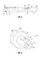
- Fig. 2 is a side, perspective view of a proximal end of the shaft assembly depicted in Fig. 1 shown unattached from a housing of the endoscopic instrument;
- Fig. 3 is a perspective view of a bushing that couples to inner and outer shaft members and to the housing of the endoscopic instrument;
- Fig. 4 is a perspective view of a spring carrier that couples to the outer shaft member depicted in Fig. 2 ;
- Fig. 5 is a side, perspective view of a selectively removable shaft assembly and bushing coupled thereto according to another embodiment of the instant disclosure
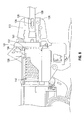
- Fig. 6 is a side view of an endoscopic instrument including the selectively removable shaft assembly and bushing depicted in Fig. 5 ;
- Fig. 7 is an isometric view of the endoscopic instrument depicted in Fig. 6 with a latching mechanism shown in a latched configuration;
- Fig. 8 is a side view of the of the endoscopic instrument depicted in Fig. 6 with the latching mechanism shown in a unlatched configuration;
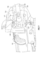
- Fig. 9 is an isometric view of the endoscopic instrument depicted in Fig. 8 with the latching mechanism shown in a unlatched configuration;
- Fig. 10 is the isometric view of Fig. 7 with the latching mechanism removed to illustrate the position of the neighboring components of the latching mechanism when the latching mechanism is in the latched configuration.
- a selectively removable shaft assembly that may be configured for use with a variety of endoscopic surgical instruments.
- the selectively removable shaft assembly includes a unique bushing configuration that couples to inner and outer shaft members of the shaft assembly to allow a user to remove the inner and outer shaft members from a housing of the endoscopic instrument.
- the unique bushing configuration also allows axial translation of the outer shaft member with respect to the inner shaft member.
- an endoscopic instrument 2 that utilizes a selectively removable shaft assembly 4 according to an embodiment of the instant disclosure is illustrated.
- the endoscopic instrument 2 that is configured for use with the shaft assembly 4 is a battery powered ultrasonic instrument 2 (e.g., an ultrasonic forceps 2).
- forceps 2 includes a housing 6 that is configured to house one or more components, e.g., transducer, waveguide and electrical circuitry that is configured for electrical communication with a battery assembly 8 of the forceps 2.
- a proximal end of housing 6 is configured to releasably couple to an ultrasonic generator 10 and the battery assembly 8.
- a distal end of the housing 6 is configured to support and releasably couple to a proximal end 12 ( Figs. 1 and 2 ) of shaft assembly 4 that is releasably positionable within a rotating assembly 13.
- Shaft assembly 4 extends from housing 6 and defines a longitudinal axis "A-A" therethrough ( Fig. 1 ).
- a distal end 14 of the shaft assembly 4 is configured to support an end effector 16 thereon.
- the operational parts of end effector 16 e.g., jaw members 18 and 20
- jaw member 20 serves as an active or oscillating blade and is configured to treat tissue.
- An activation button 24 places the forceps 2 in one or more modes of operation and generator 10 is configured to convert electrical energy produced by the battery assembly 8 into ultrasonic energy.
- generator 10 includes a transducer (not explicitly shown) that is configured to convert electrical energy to mechanical energy that produces motion in a waveguide (not explicitly shown) that is in operative communication with the active jaw member 20.
- Shaft assembly 4 includes inner and outer shaft members 26 and 28 respectively.
- the inner shaft member 26 encases an ultrasonic shaft (not explicitly shown).
- outer shaft member 28 which is movable axially along the longitudinal axis "A-A" to move jaw member 18
- inner shaft 26 is fixed as it does not move axially to move jaw member 18. Rather, inner shaft 26 supports pivot points (not explicitly shown) for jaw member 18 to open and close.
- the ultrasonic shaft member is rigidly coupled to the housing 6 and is configured to house one or more components of the forceps 2, e.g., the waveguide and/or transducer therein. In some embodiments, however, the ultrasonic shaft may be configured to releasably couple to the housing 6.
- Outer shaft member 28 is configured to support the jaw members 18 and 20 thereon ( Fig. 1 ) and is configured to releasably couple to one or more components, e.g., a spring carrier 42 ( Fig. 4 ), of the housing 6.
- a spring carrier 42 Fig. 4
- the inner shaft member 26 and outer shaft member 28 may be removed from the housing 6 so that the housing 6 including the ultrasonic shaft may be sterilized.
- outer shaft 28 moves axially along the longitudinal axis to open and close jaw member 18.
- slots 30 and 32 are defined through the inner shaft member 26 and are aligned with one or more corresponding first slots 32 defined through the outer shaft member 28 ( Fig. 2 ).
- Slots 30 and 32 may include any suitable configuration.
- slots 30 and 32 include a generally elongated configuration.
- slots 30 are smaller in length than slots 32, as best seen in Fig. 2 .
- Providing slots 30 with a smaller length allows the outer shaft member 28 to move axially a predetermined distance with respect to the inner shaft member 26 to move the jaw member 18 from an open configuration ( Fig. 1 ) to a closed configuration (not explicitly shown).
- slots 30 are completely filled by a boss 50 on bushing 36 to restrict axial movement of inner shaft member 26.
- First slots 32 are longer than slots 30 to allow axial movement of outer shaft member 28 to move jaw member 18 from the open configuration to closed configuration.
- first slots 32 can be sized to limit a maximum opening of jaw member 18.
- a bushing 36 is illustrated including a base 38 and an elongated stem 41 extending distally therefrom.
- Bushing 36 is configured to fixedly couple to the inner and outer shaft members 26, 28.
- corresponding mechanical interfaces e.g., resilient fingers 34
- stem 41 is biased radially inward therefrom to engage slots 30 and 32 on the respective inner and outer shaft members 26, 28.
- Base 38 is configured to key the bushing 36 to the rotation of the rotating assembly 13. Accordingly, base 38 includes a plurality of planar surfaces 38a (or splines not explicitly shown) that are configured to engage corresponding surfaces of the rotating assembly 13. In the embodiment illustrated in Fig. 3 , the base 38 includes eight (8) planar surfaces 38a forming a generally octagonal configuration.
- An aperture 40 of suitable configuration extends through the bushing 36 and is configured to receive the outer shaft member 28 therethrough for coupling the outer shaft member 28 to the spring carrier 42 ( Fig. 4 ).
- Spring carrier 42 includes a generally elongated proximal end 44 of suitable configuration that is configured to support a spring (not explicitly shown) thereon ( Fig. 4 ).
- One or more resilient bosses 50 extend radially inward from the elongated proximal end 44 ( Fig. 4 ) and are configured to releasably couple to one or more corresponding slots 52 disposed at the proximal end 12 of the outer shaft member 28 ( Fig. 2 ).
- the resilient bosses 50 include a chamfered edge 53 ( Fig. 4 ) that is configured to facilitate engaging and disengaging the outer shaft member 28 with the spring carrier 42.
- an edge 15 ( Fig. 2 ) of the outer shaft member 28 that defines the slots 52 cams the resilient boss 50 outwardly.
- Spring carrier 42 also includes a generally circumferential distal end 46 that is configured to engage an internal wall (not explicitly shown) of the housing 6.
- a plurality of radial slots 54 are formed in a distal face 56 of the spring carrier 42 and are configured to engage corresponding mating features (not explicitly shown) on the internal wall of the of the housing 6. More particularly, when the movable handle 22 is moved proximally, the spring carrier 42 is moved distally toward the distal end of the housing 6 (e.g., the spring carrier 42 is moved to an extreme forward position) and into engagement with the mating features on the internal wall of the housing to "lock" the spring carrier 42 and prevent the spring carrier 42 from rotating with the outer shaft member 28.
- the bushing 36 including the inner and outer shaft members 26, 28 may be removed so that the housing 6 and ultrasonic shaft coupled thereto may be completely cleaned and resterilized by an autoclave.
- the moveable handle 22 is moved proximally to move the spring carrier 42 to the extreme forward position to lock the spring carrier 42 as described above.
- the outer shaft member 28 With the spring carrier 42 in the locked position, the outer shaft member 28 may be rotated, e.g., in a counter-clockwise direction, to disengage the resilient bosses 50 from the slots 52 of the outer shaft member 28. Once the resilient bosses 50 are disengaged from the slots 52, the bushing 36 including the inner and outer shaft members 26, 28 may be uncoupled from the housing 6.
- the bushing 36 including the inner and outer shaft members 26, 28 may be slid over the ultrasonic shaft and the outer shaft member 28 may be reinserted into the spring carrier 42. Once inserted into the spring carrier 42, the outer shaft member 28 may be rotated, e.g., in a clockwise direction, to engage the resilient bosses 50 with the slots 52 of the outer shaft member 28.
- the unique configuration of the bushing 36 and shaft assembly 4 of the present disclosure enables a user to quickly and easily couple and uncouple the bushing 36 including the inner and outer shaft members 26, 28 from the housing 6 of the forceps 2 for sterilization of the forceps 2.
- a shaft assembly 104 according to an alternate embodiment of the present disclosure is illustrated.
- Forceps 102 and shaft assembly 104 are substantially similar to forceps 2 and shaft assembly 4. In view thereof, only those features unique to the forceps 102 and/or shaft assembly 104 are described in detail.
- outer shaft member 128 includes a proximal flange 129 of suitable configuration ( Fig. 5 ).
- Proximal flange 129 is configured for engagement with a "guillotine" type locking member 131 that is operably coupled to a spring carrier 142 ( Figs. 6 , 8 and 10 ) to couple the outer shaft member 128 to the spring carrier 142.
- the locking member 131 slides over a front face 133 ( Fig. 5 ) of the proximal flange 129 to couple the outer shaft member 128 to the spring carrier 142.
- This method for coupling the outer shaft member 128 to the spring carrier 142 allows the proximal flange 129 to freely rotate behind the locking member 131 such that the spring carrier 142 does not rotate with the outer shaft member 128.
- Locking member 131 includes a bottom portion with a generally "C-shaped” configuration that rests on an outer surface of the outer shaft member 128, see Fig. 10 for example. This "C-shaped" configuration allows the locking member 131 to move in and out of engagement with the outer shaft member 128 and allows the outer shaft member 128 to move axially with the spring carrier 142.
- a top portion 135 ( Figs. 6 , 8 and 10 ) of the locking member 131 includes a detent 137 ( Figs. 6-10 ) that is configured to engage a corresponding aperture 139 ( Fig. 7 ) on a latch 141 ( Figs. 6-9 ).
- the detent 137 and aperture 139 couple the locking member 131 to the latch 141 to allow the locking member 131 and latch 141 to move in unison.
- the latch 141 is operably disposed in the housing 106 and is accessible to a user from a top portion of the housing 106.
- the latch 141 also includes an aperture 143 of suitable configuration that allows passage of the bushing 136 including the outer shaft member 128 therethrough ( Figs. 7 and 9 ).
- An interior wall 151 ( Figs. 7 and 9 ) that defines the aperture 143 is configured to releasably engage an annular groove 145 (as best seen in Fig. 5 ) disposed at a proximal end 147 of the bushing 136.
- pulling the latch 141 a predetermined distance e.g., upwards
- the bushing 136 includes a pair of mechanical interfaces (e.g., detents 134) that are configured to engage corresponding slots 130 and 132, see Figs. 5 , 6 and 8 ; in these figures, the detent 134 is shown engaged with the slot 130 and as such the slot 130 is not explicitly shown.
- detents 134 e.g., a pair of mechanical interfaces
- a guide slot 152 ( Fig. 5 ) is provided to replace slot 52 of the outer shaft member 28 and is configured to engage a corresponding detent 156 that extends from the spring carrier 142 ( Fig. 9 ). This configuration of the guide slot 152 and detent 156 facilitates aligning the annular groove 145 and the inner wall 151 of the locking member 131.
- a stop member 158 ( Figs. 6 and 8 ) defined on an interior surface of the housing 106 is provided and is configured to contact the top surface 135 of the locking member 131 when the latch 141 has been pulled a predetermined distance (e.g., upwards), see Fig. 8 for example; this prevents a user from "over-pulling" the latch 141.
- the latch 141 includes an optional pair of opposing arms 153 that each include a respective detent 155 (see Fig. 9 for example) that seats within a corresponding pocket (not explicitly shown) disposed within an interior wall of the housing.
- the detents 155 seated within the pockets are configured to further limit movement of the latch 141.
- a user pulls the latch 141 (e.g., upwards) to disengage the locking member 131 from the proximal flange 129 and the latch 141 from the annular groove 145.
- the bushing 136 including inner and outer shaft members 126, 128 may be uncoupled from the housing 106.
- the user re-inserts the bushing 136 including inner and outer shaft members 126, 128 into the housing 106 and pushes the latch 141 (e.g.,downwards) to engage the locking 131 member with the proximal flange 129 and the latch 141 with the annular groove 145.
- the latch 141 e.g.,downwards
- the unique configuration of the bushing 136 and shaft assembly 104 of the present disclosure enables a user to quickly and easily couple and uncouple the bushing 136 including the inner and outer shaft members 126, 128 from the housing 6 of the forceps 102 for sterilization thereof.
- the ultrasonic shaft may be configured to couple and uncouple with the bushings 36, 136 including inner and outer shafts 26, 126 and 28, 128, respectively.
- one or more components associated with the forceps 2, 102 may be utilized in conjunction with the shaft assemblies 4, 104.
- a rear knob 3 ( Fig. 1 ) may be utilized to release the ultrasonic shaft.
- the rotating assemblies 13, 113 are held immobile while the rear knob 3 is turned to unscrew the ultrasonic shaft.
- the ultrasonic shaft is unscrewed, it along with the shaft assemblies 4, 104 may be uncoupled as described above.
Abstract
Description
- The present disclosure relates to endoscopic instruments and, more particularly, to endoscopic instruments including selectively removable shaft assemblies.
- Endoscopic instruments are well known in the medical arts. For example, an electrosurgical endoscopic forceps (a closed forceps) is utilized in surgical procedures, e.g., laparoscopic surgical procedure, where access to tissue is accomplished through a cannula or other suitable device positioned in an opening on a patient. The endoscopic forceps, typically, includes a housing, a handle assembly including a movable handle, a shaft and an end effector assembly attached to a distal end of the shaft. The end effector includes jaw members configured to manipulate tissue, e.g., grasp and seal tissues. The endoscopic instrument may be configured to utilize one or more types of energies including, but not limited to, RF energy, microwave energy, ultra sound to treat tissue.
- Another type of endoscopic instrument that may be utilized in laparoscopic surgical procedures is an ultrasonic endoscopic forceps. The ultrasonic endoscopic forceps is similar in configuration to the electrosurgical endoscopic forceps. Unlike the electrosurgical endoscopic forceps, however, the ultrasonic endoscopic forceps utilizes ultrasonic energy to treat tissue.
- As is conventional with both of the above endoscopic instruments, the shaft of these instruments is, typically, rigidly attached to the endoscopic instrument, i.e., the shaft is non-removable from the housings of the respective instruments. Having an endoscopic instrument with a non-removable shaft may prove problematic during the operative life cycle of the endoscopic instrument. For example, if the endoscopic instrument is to be re-used, the entire device is, typically, sterilized via an autoclaving process or the like. As can be appreciated, sterilizing an endoscopic instrument with the shaft including the end effector attached may prove difficult. In particular, it may prove difficult to sterilize between small spaces of the shaft, e.g., spaces at a distal end of the shaft adjacent the end effector.
- In view of the foregoing, it may prove advantageous in the medical arts to provide endoscopic instruments that include selectively removable shaft assemblies.
- In the drawings and in the descriptions that follow, the term "proximal," as is traditional, will refer to an end which is closer to the user, while the term "distal" will refer to an end that is farther from the user.
- As used herein, "endoscopic instrument" generally refers to any surgical instrument that is configured for access into a body cavity. The endoscopic instrument may be configured to grasp tissue or may be configured to grasp and subsequently electrosurgically treat tissue, e.g., an electrosurgical endoscopic device. In the latter instance, the endoscopic instrument may be configured to couple to one or more suitable electrosurgical energy sources. Or, the endoscopic instrument may be battery powered. As it is used herein, "electrosurgical procedure" generally refers to any electrosurgical procedure involving any form of energy, such as, for example, microwave energy, radiofrequency (RF) energy, ultrasonic energy, thermal energy or combination thereof.
- An aspect of the present disclosure provides an endoscopic instrument. The endoscopic instrument includes a housing including an elongated shaft assembly extending distally therefrom. The elongated shaft assembly has inner and outer shaft members. The inner and outer shaft members are removably coupled to the housing and the outer shaft member is movable with respect to the inner shaft member. An end effector is operably supported at the distal end of the outer shaft member or of the shaft assembly and includes a pair of jaw members configured for treating tissue. A bushing may be operably coupled to the inner and outer shaft members of the shaft assembly and configured to selectively and releasably couple to the housing. In certain instances, the bushing may include one or more resilient fingers or one or more mechanical interfaces that are configured to engage one or more slots defined through the inner shaft member and one or more slots defined through the outer shaft member. Alternatively put, the bushing is coupled to the inner and outer shaft members to allow a user to remove the bushing and the inner and outer shaft members from the housing as a unit. The coupling of the bushing and the inner and outer shaft members allows axial translation of the outer shaft member with respect to the inner shaft member. In certain instances, slot(s) on the outer shaft member is/are longer than the slot(s) on the inner shaft member to allow the outer shaft member to translate with respect to the inner shaft member.
- A spring carrier includes one or more resilient bosses that are configured to releasably engage one or more second slots defined through the outer shaft member at a proximal end thereof to release the inner and outer shaft members from the housing when the outer shaft member is rotated with respect to the spring carrier. The spring carrier is configured to provide axial movement of the outer shaft member when a handle assembly of the endoscopic instrument is actuated. In certain instance, the resilient boss(es) includes a chamfered edge that is configured contact an edge of the corresponding second slot to move the resilient boss(es) out of engagement with the corresponding second slot when the outer shaft member is rotated. The spring carrier may include a plurality of radial slots on a distal face thereof. The plurality of radial slots are configured to engage a corresponding plurality of mating features disposed on an interior wall of the housing when the spring carrier is in a forward-most position within the housing. Engagement between the plurality of radial slots and corresponding plurality of mating features prevents rotation of the spring carrier when outer shaft member is rotated.
- An aspect of the present disclosure provides an endoscopic instrument. The endoscopic instrument includes a housing that includes an elongated shaft assembly extending distally therefrom. The elongated shaft assembly has inner and outer shaft members. The inner and outer shaft members are removably coupled to the housing and the outer shaft member is movable with respect to the inner shaft member. An end effector is operably supported at the distal end of the outer shaft member or of the shaft assembly. A bushing is operably coupled to the inner and outer shaft members of the shaft assembly and is selectively and releasably coupled to the housing. The bushing includes a generally annular groove located at a proximal end thereof. A latch is operably disposed on the housing and is movable with respect thereto for selectively and releasably engaging the annular groove on the bushing to release the inner and outer shaft members from the housing.
- The latch may include a pair of opposing arms. Each of the opposing arms may include a respective detent that seats within a corresponding pocket disposed within an interior wall of the housing. The detents may be seated within the pockets and configured to limit movement of the latch.
- The latch may include an aperture that is configured to receive the bushing and the outer shaft member therethrough. Moreover, the latch may include a generally elongated slot therein that is configured to engage a corresponding detent disposed on a locking member that is positioned proximal the latch and movable therewith. In this instance, the locking member may be configured to couple the outer shaft member to a spring carrier configured to provide axial movement of the outer shaft member when a handle assembly of the endoscopic instrument is actuated. The outer shaft member may include a flange disposed at a proximal end thereof that is configured to engage the locking member.
- An aspect of the instant disclosure provides an endoscopic instrument. The endoscopic instrument includes a housing that includes an elongated shaft assembly extending distally therefrom. The elongated shaft assembly has inner and outer shaft members. The inner and outer shaft members are removably coupled to the housing and the outer shaft member is movable with respect to the inner shaft member. A rotating assembly is operably coupled to the housing and is configured to rotate the inner and outer shaft members. A bushing is removably coupled to the rotating assembly and is operably coupled to the inner and outer shaft members and selectively and releasably coupled to the rotating assembly. An end effector is operably supported at the distal end of the outer shaft member or of the shaft assembly. The bushing includes one or more mechanical interfaces that are configured to engage one or more slots defined through the inner shaft member and at least one slot defined through the outer shaft member.
- The mechanical interfaces of the bushing may be in the form of one or more resilient fingers. In this instance, the at least one slot on the outer shaft member is longer than the at least one slot on the inner shaft member to allow the outer shaft member to translate with respect to the inner shaft member.
- A spring carrier may be provided and may include at least one resilient boss. The resilient boss may be configured to releasably engage at least one second slot defined through the outer shaft member at a proximal end thereof and configured to release the inner and outer shaft members from the housing when the outer shaft member is rotated with respect to the spring carrier. The at least one resilient boss may include a chamfered edge that is configured to contact an edge of the corresponding second slot to move the at least one resilient boss out of engagement with the corresponding second slot when the outer shaft member is rotated. The spring carrier may be further configured to provide axial movement of the outer shaft member when a handle assembly of the endoscopic instrument is actuated. The spring carrier may include a plurality of radial slots defined on a distal face thereof. The plurality of radial slots may be configured to engage a corresponding plurality of mating features disposed on an interior wall of the housing when the spring carrier is moved to a forward-most position within the housing. Engagement between the plurality of radial slots and corresponding plurality of mating features prevents rotation of the spring carrier when outer shaft member is rotated. Other means for preventing rotation of the spring carrier when the outer shaft member is rotated could be provided, particularly locking means, when the spring carrier is moved into a position, e.g. a forward-most position, when the moveable handle is actuated. The apparatus may comprise a rotating assembly configured to rotate the bush, the inner and outer shaft members and the spring carrier when the spring carrier is not in the position or the forward-most position.
- The mechanical interfaces of the bushing may be in the form of one or more detents. In this instance, the bushing may include a generally annular groove that is located at a proximal end thereof.
- A latch may be operably disposed on the housing and may be movable with respect thereto for selectively and releasably engaging the annular groove on the bushing to release the inner and outer shaft members from the housing. The latch may include a pair of opposing arms. Each of the opposing arms may include a respective detent that seats within a corresponding pocket disposed within an interior wall of the housing. The detents may be seated within the pockets and configured to limit movement of the latch. The latch may include an aperture that is configured to receive the bushing and the outer shaft member therethrough. The latch may include a generally elongated slot therein that is configured to engage a corresponding detent disposed on a locking member positioned proximal the latch and movable therewith. The locking member may be configured to couple the outer shaft member to a spring carrier configured to provide axial movement of the outer shaft member when a handle assembly of the endoscopic instrument is actuated. The outer shaft member may include a flange that is disposed at a proximal end thereof that is configured to engage the locking member.
- In the various aspects and embodiments described above, relative movement of the inner and outer shaft members is operable to move the jaw members between open and closed positions.
- In the various aspects and embodiments described above, the housing comprises a moveable handle operably coupled with the outer shaft member to effect movement thereof relative to the inner shaft member. In an embodiment, a/the spring carrier couples between the outer shaft member and the moveable handle. In an embodiment, means are provided for uncoupling the spring carrier from the outer shaft, such as a latch means (e.g. the latch described above) or resilient boss means (such as resilient boss described above). The means may be user activatable, such as by rotation of the outer shaft or by actuating a/the latch.
- Various embodiments of the present disclosure are described hereinbelow with reference to the drawings, wherein:
-
Fig. 1 is a side, perspective view of an endoscopic instrument including a selectively removable shaft assembly according to an embodiment of the present disclosure; -
Fig. 2 is a side, perspective view of a proximal end of the shaft assembly depicted inFig. 1 shown unattached from a housing of the endoscopic instrument; -
Fig. 3 is a perspective view of a bushing that couples to inner and outer shaft members and to the housing of the endoscopic instrument; -
Fig. 4 is a perspective view of a spring carrier that couples to the outer shaft member depicted inFig. 2 ; -
Fig. 5 is a side, perspective view of a selectively removable shaft assembly and bushing coupled thereto according to another embodiment of the instant disclosure; -
Fig. 6 is a side view of an endoscopic instrument including the selectively removable shaft assembly and bushing depicted inFig. 5 ; -
Fig. 7 is an isometric view of the endoscopic instrument depicted inFig. 6 with a latching mechanism shown in a latched configuration; -
Fig. 8 is a side view of the of the endoscopic instrument depicted inFig. 6 with the latching mechanism shown in a unlatched configuration; -
Fig. 9 is an isometric view of the endoscopic instrument depicted inFig. 8 with the latching mechanism shown in a unlatched configuration; and -
Fig. 10 is the isometric view ofFig. 7 with the latching mechanism removed to illustrate the position of the neighboring components of the latching mechanism when the latching mechanism is in the latched configuration. - Detailed embodiments of the present disclosure are disclosed herein; however, the disclosed embodiments are merely examples of the disclosure, which may be embodied in various forms. Therefore, specific structural and functional details disclosed herein are not to be interpreted as limiting, but merely as a basis for the claims and as a representative basis for teaching one skilled in the art to variously employ the present disclosure in virtually any appropriately detailed structure.
- As noted above, it may prove useful in the medical arts to provide an endoscopic instrument that includes a selectively removable shaft assembly. In accordance with the instant disclosure, a selectively removable shaft assembly that may be configured for use with a variety of endoscopic surgical instruments is provided. The selectively removable shaft assembly includes a unique bushing configuration that couples to inner and outer shaft members of the shaft assembly to allow a user to remove the inner and outer shaft members from a housing of the endoscopic instrument. The unique bushing configuration also allows axial translation of the outer shaft member with respect to the inner shaft member.
- With reference to
Fig. 1 , anendoscopic instrument 2 that utilizes a selectivelyremovable shaft assembly 4 according to an embodiment of the instant disclosure is illustrated. For illustrative purposes, theendoscopic instrument 2 that is configured for use with theshaft assembly 4 is a battery powered ultrasonic instrument 2 (e.g., an ultrasonic forceps 2). Briefly,forceps 2 includes a housing 6 that is configured to house one or more components, e.g., transducer, waveguide and electrical circuitry that is configured for electrical communication with abattery assembly 8 of theforceps 2. A proximal end of housing 6 is configured to releasably couple to anultrasonic generator 10 and thebattery assembly 8. A distal end of the housing 6 is configured to support and releasably couple to a proximal end 12 (Figs. 1 and2 ) ofshaft assembly 4 that is releasably positionable within a rotatingassembly 13.Shaft assembly 4 extends from housing 6 and defines a longitudinal axis "A-A" therethrough (Fig. 1 ). Adistal end 14 of theshaft assembly 4 is configured to support anend effector 16 thereon. The operational parts of end effector 16 (e.g.,jaw members 18 and 20) are movable relative to one another upon actuation of amovable handle assembly 22 coupled to housing 6. - In the illustrated embodiment,
jaw member 20 serves as an active or oscillating blade and is configured to treat tissue. Anactivation button 24 places theforceps 2 in one or more modes of operation andgenerator 10 is configured to convert electrical energy produced by thebattery assembly 8 into ultrasonic energy. More particularly,generator 10 includes a transducer (not explicitly shown) that is configured to convert electrical energy to mechanical energy that produces motion in a waveguide (not explicitly shown) that is in operative communication with theactive jaw member 20. - With reference now to
Fig. 2 , theproximal end 12 of theshaft assembly 4 is illustrated to show the operative components of theshaft assembly 4.Shaft assembly 4 includes inner andouter shaft members inner shaft member 26 encases an ultrasonic shaft (not explicitly shown). Unlikeouter shaft member 28 which is movable axially along the longitudinal axis "A-A" to movejaw member 18,inner shaft 26 is fixed as it does not move axially to movejaw member 18. Rather,inner shaft 26 supports pivot points (not explicitly shown) forjaw member 18 to open and close. The ultrasonic shaft member is rigidly coupled to the housing 6 and is configured to house one or more components of theforceps 2, e.g., the waveguide and/or transducer therein. In some embodiments, however, the ultrasonic shaft may be configured to releasably couple to the housing 6. -
Outer shaft member 28 is configured to support thejaw members Fig. 1 ) and is configured to releasably couple to one or more components, e.g., a spring carrier 42 (Fig. 4 ), of the housing 6. Thus, after use, theinner shaft member 26 and outer shaft member 28 (including thejaw members outer shaft 28 moves axially along the longitudinal axis to open andclose jaw member 18. - One or
more slots 30 are defined through theinner shaft member 26 and are aligned with one or more correspondingfirst slots 32 defined through the outer shaft member 28 (Fig. 2 ).Slots slots slots 30 are smaller in length thanslots 32, as best seen inFig. 2 . Providingslots 30 with a smaller length allows theouter shaft member 28 to move axially a predetermined distance with respect to theinner shaft member 26 to move thejaw member 18 from an open configuration (Fig. 1 ) to a closed configuration (not explicitly shown). Specifically,slots 30 are completely filled by aboss 50 onbushing 36 to restrict axial movement ofinner shaft member 26.First slots 32 are longer thanslots 30 to allow axial movement ofouter shaft member 28 to movejaw member 18 from the open configuration to closed configuration. As can be appreciated,first slots 32 can be sized to limit a maximum opening ofjaw member 18. - With reference to
Fig. 3 , abushing 36 is illustrated including abase 38 and anelongated stem 41 extending distally therefrom.Bushing 36 is configured to fixedly couple to the inner andouter shaft members stem 41 and are biased radially inward therefrom to engageslots outer shaft members -
Base 38 is configured to key thebushing 36 to the rotation of the rotatingassembly 13. Accordingly,base 38 includes a plurality ofplanar surfaces 38a (or splines not explicitly shown) that are configured to engage corresponding surfaces of the rotatingassembly 13. In the embodiment illustrated inFig. 3 , thebase 38 includes eight (8)planar surfaces 38a forming a generally octagonal configuration. - An
aperture 40 of suitable configuration extends through thebushing 36 and is configured to receive theouter shaft member 28 therethrough for coupling theouter shaft member 28 to the spring carrier 42 (Fig. 4 ). -
Spring carrier 42 includes a generally elongatedproximal end 44 of suitable configuration that is configured to support a spring (not explicitly shown) thereon (Fig. 4 ). One or more resilient bosses 50 (oneresilient boss 50 illustrated in the drawings) extend radially inward from the elongated proximal end 44 (Fig. 4 ) and are configured to releasably couple to one or morecorresponding slots 52 disposed at theproximal end 12 of the outer shaft member 28 (Fig. 2 ). Theresilient bosses 50 include a chamfered edge 53 (Fig. 4 ) that is configured to facilitate engaging and disengaging theouter shaft member 28 with thespring carrier 42. In particular, as theouter shaft member 28 is rotated (e.g., counter-clockwise) an edge 15 (Fig. 2 ) of theouter shaft member 28 that defines theslots 52 cams theresilient boss 50 outwardly. -
Spring carrier 42 also includes a generally circumferentialdistal end 46 that is configured to engage an internal wall (not explicitly shown) of the housing 6. In particular, a plurality ofradial slots 54 are formed in adistal face 56 of thespring carrier 42 and are configured to engage corresponding mating features (not explicitly shown) on the internal wall of the of the housing 6. More particularly, when themovable handle 22 is moved proximally, thespring carrier 42 is moved distally toward the distal end of the housing 6 (e.g., thespring carrier 42 is moved to an extreme forward position) and into engagement with the mating features on the internal wall of the housing to "lock" thespring carrier 42 and prevent thespring carrier 42 from rotating with theouter shaft member 28. - In use, after a surgical procedure, e.g., an ultrasonic sealing procedure, has been completed, the
bushing 36 including the inner andouter shaft members moveable handle 22 is moved proximally to move thespring carrier 42 to the extreme forward position to lock thespring carrier 42 as described above. With thespring carrier 42 in the locked position, theouter shaft member 28 may be rotated, e.g., in a counter-clockwise direction, to disengage theresilient bosses 50 from theslots 52 of theouter shaft member 28. Once theresilient bosses 50 are disengaged from theslots 52, thebushing 36 including the inner andouter shaft members - To re-attach the
bushing 36 including the inner andouter shaft members 26, 28 (or in some embodiments, anew bushing 36 including new inner andouter shaft members bushing 36 including the inner andouter shaft members outer shaft member 28 may be reinserted into thespring carrier 42. Once inserted into thespring carrier 42, theouter shaft member 28 may be rotated, e.g., in a clockwise direction, to engage theresilient bosses 50 with theslots 52 of theouter shaft member 28. - The unique configuration of the
bushing 36 andshaft assembly 4 of the present disclosure enables a user to quickly and easily couple and uncouple thebushing 36 including the inner andouter shaft members forceps 2 for sterilization of theforceps 2. - With reference to
Figs. 5-10 ashaft assembly 104 according to an alternate embodiment of the present disclosure is illustrated. Forceps 102 andshaft assembly 104 are substantially similar toforceps 2 andshaft assembly 4. In view thereof, only those features unique to the forceps 102 and/orshaft assembly 104 are described in detail. - Unlike
outer shaft member 28,outer shaft member 128 includes aproximal flange 129 of suitable configuration (Fig. 5 ).Proximal flange 129 is configured for engagement with a "guillotine"type locking member 131 that is operably coupled to a spring carrier 142 (Figs. 6 ,8 and10 ) to couple theouter shaft member 128 to thespring carrier 142. In one embodiment, the lockingmember 131 slides over a front face 133 (Fig. 5 ) of theproximal flange 129 to couple theouter shaft member 128 to thespring carrier 142. This method for coupling theouter shaft member 128 to thespring carrier 142 allows theproximal flange 129 to freely rotate behind the lockingmember 131 such that thespring carrier 142 does not rotate with theouter shaft member 128. - Locking
member 131 includes a bottom portion with a generally "C-shaped" configuration that rests on an outer surface of theouter shaft member 128, seeFig. 10 for example. This "C-shaped" configuration allows the lockingmember 131 to move in and out of engagement with theouter shaft member 128 and allows theouter shaft member 128 to move axially with thespring carrier 142. - A top portion 135 (
Figs. 6 ,8 and10 ) of the lockingmember 131 includes a detent 137 (Figs. 6-10 ) that is configured to engage a corresponding aperture 139 (Fig. 7 ) on a latch 141 (Figs. 6-9 ). Thedetent 137 andaperture 139 couple the lockingmember 131 to thelatch 141 to allow the lockingmember 131 and latch 141 to move in unison. - The
latch 141 is operably disposed in the housing 106 and is accessible to a user from a top portion of the housing 106. Thelatch 141 also includes anaperture 143 of suitable configuration that allows passage of thebushing 136 including theouter shaft member 128 therethrough (Figs. 7 and9 ). - An interior wall 151 (
Figs. 7 and9 ) that defines theaperture 143 is configured to releasably engage an annular groove 145 (as best seen inFig. 5 ) disposed at aproximal end 147 of thebushing 136. In particular, pulling the latch 141 a predetermined distance (e.g., upwards) disengages theinterior wall 151 from theannular groove 145 and disengages theflange 129 from the lockingmember 131 so that thebushing 136 including the inner andouter shaft members spring carrier 142. Likewise, pushing the latch 141 a predetermined distance (e.g., downwards) engages theinterior wall 151 with theannular groove 145 and engages theflange 129 with the lockingmember 131 so that thebushing 136 including the inner 126 andouter shaft members 128 may be coupled to thespring carrier 142. - Unlike bushing 36 that includes a pair of
resilient fingers 34, thebushing 136 includes a pair of mechanical interfaces (e.g., detents 134) that are configured to engage corresponding slots 130 and 132, seeFigs. 5 ,6 and8 ; in these figures, thedetent 134 is shown engaged with the slot 130 and as such the slot 130 is not explicitly shown. - A guide slot 152 (
Fig. 5 ) is provided to replaceslot 52 of theouter shaft member 28 and is configured to engage acorresponding detent 156 that extends from the spring carrier 142 (Fig. 9 ). This configuration of theguide slot 152 anddetent 156 facilitates aligning theannular groove 145 and theinner wall 151 of the lockingmember 131. - A stop member 158 (
Figs. 6 and8 ) defined on an interior surface of the housing 106 is provided and is configured to contact thetop surface 135 of the lockingmember 131 when thelatch 141 has been pulled a predetermined distance (e.g., upwards), seeFig. 8 for example; this prevents a user from "over-pulling" thelatch 141. - In some embodiments, such as the one illustrated in
Figs. 5-10 , thelatch 141 includes an optional pair of opposingarms 153 that each include a respective detent 155 (seeFig. 9 for example) that seats within a corresponding pocket (not explicitly shown) disposed within an interior wall of the housing. Thedetents 155 seated within the pockets are configured to further limit movement of thelatch 141. - In use, to uncouple the
bushing 136 including inner andouter shaft members member 131 from theproximal flange 129 and thelatch 141 from theannular groove 145. - Once disengaged, the
bushing 136 including inner andouter shaft members - To re-couple the
bushing 136 including inner andouter shaft members bushing 136 including inner andouter shaft members proximal flange 129 and thelatch 141 with theannular groove 145. - As described above with respect to the
bushing 36 andshaft assembly 4, the unique configuration of thebushing 136 andshaft assembly 104 of the present disclosure enables a user to quickly and easily couple and uncouple thebushing 136 including the inner andouter shaft members - From the foregoing and with reference to the various figure drawings, those skilled in the art will appreciate that certain modifications can also be made to the present disclosure without departing from the scope of the same. For example, and as noted above, the ultrasonic shaft may be configured to couple and uncouple with the
bushings outer shafts forceps 2, 102 may be utilized in conjunction with theshaft assemblies Fig. 1 ) may be utilized to release the ultrasonic shaft. In this instance, the rotatingassemblies shaft assemblies - While several embodiments of the disclosure have been shown in the drawings, it is not intended that the disclosure be limited thereto, as it is intended that the disclosure be as broad in scope as the art will allow and that the specification be read likewise. Therefore, the above description should not be construed as limiting, but merely as exemplifications of particular embodiments. Those skilled in the art will envision other modifications within the scope and spirit of the claims appended hereto.
Claims (14)
- An endoscopic instrument, comprising:a housing including an elongated shaft assembly extending distally therefrom, the elongated shaft assembly having inner and outer shaft members, the inner and outer shaft members removably coupled to the housing and the outer shaft member movable with respect to the inner shaft member;an end effector operably supported at the distal end of the outer shaft member; anda bushing operably coupled to the inner and outer shaft members of the shaft assembly and selectively and releasably coupled to the housing,wherein the bushing includes at least one resilient finger configured to engage at least one slot defined through the inner shaft member and at least one slot defined through the outer shaft member to release the inner and outer shaft members from the housing.
- An endoscopic instrument according to claim 1, wherein the endoscopic instrument is an ultrasonic instrument configured to ultrasonically treat tissue.
- An endoscopic instrument, comprising:a housing including an elongated shaft assembly extending distally therefrom, the elongated shaft assembly having inner and outer shaft members, the inner and outer shaft members removably coupled to the housing and the outer shaft member movable with respect to the inner shaft member;an end effector operably supported at the distal end of the outer shaft member;a bushing operably coupled to the inner and outer shaft members of the shaft assembly and selectively and releasably coupled to the housing, the bushing including a generally annular groove located at a proximal end thereof; anda latch operably disposed on the housing and movable with respect thereto for selectively and releasably engaging the annular groove on the bushing to release the inner and outer shaft members from the housing.
- An endoscopic instrument, comprising:a housing including an elongated shaft assembly extending distally therefrom, the elongated shaft assembly having inner and outer shaft members, the inner and outer shaft members removably coupled to the housing and the outer shaft member movable with respect to the inner shaft member;a rotating assembly operably coupled to the housing and configured to rotate the inner and outer shaft members;a bushing removably coupled to the rotating assembly and operably coupled to the inner and outer shaft members and selectively and releasably coupled to the rotating assembly; andan end effector operably supported at the distal end of the outer shaft member,wherein the bushing includes at least one mechanical interface configured to engage at least one slot defined through the inner shaft member and at least one slot defined through the outer shaft member to release the inner and outer shaft members from the housing.
- An endoscopic instrument according to claim 4, wherein the at least one mechanical interface of the bushing is in the form of one of an at least one resilient finger and at least one detent.
- An endoscopic instrument according to claim 1, 2, 4 or 5, wherein the at least one slot on the outer shaft member is longer than the at least one slot on the inner shaft member to allow the outer shaft member to translate with respect to the inner shaft member.
- An endoscopic instrument according to claim 1, 2, 4, 5 or 6, further including a spring carrier including at least one resilient boss configured to releasably engage at least one second slot defined through the outer shaft member at a proximal end thereof and configured to release the inner and outer shaft members from the housing when the outer shaft member is rotated with respect to the spring carrier, the spring carrier further configured to provide axial movement of the outer shaft member when a handle assembly of the endoscopic instrument is actuated.
- An endoscopic instrument according to claim 7, wherein the at least one resilient boss includes a chamfered edge that is configured to contact an edge of the corresponding second slot to move the at least one resilient boss out of engagement with the corresponding second slot when the outer shaft member is rotated.
- An endoscopic instrument according to claim 7 or 8, wherein the spring carrier includes a plurality of radial slots defined on a distal face thereof, the plurality of radial slots configured to engage a corresponding plurality of mating features disposed on an interior wall of the housing when the spring carrier is moved to a forward-most position within the housing, wherein engagement between the plurality of radial slots and corresponding plurality of mating features prevents rotation of the spring carrier when outer shaft member is rotated.
- An endoscopic instrument according to claim 4, wherein the bushing includes a generally annular groove located at a proximal end thereof, and wherein a latch is operably disposed on the housing and movable with respect thereto for selectively and releasably engaging the annular groove on the bushing to release the inner and outer shaft members from the housing.
- An endoscopic instrument according to claim 3 or 10, wherein the latch includes a pair of opposing arms each including a respective detent that seats within a corresponding pocket disposed within an interior wall of the housing, the detents seated within the pockets configured to limit movement of the latch.
- An endoscopic instrument according to claim 3, 10 or 11, wherein the latch includes an aperture that is configured to receive the bushing and the outer shaft member therethrough.
- An endoscopic instrument according to claim 3, 10, 11 or 12, wherein the latch includes a generally elongated slot therein that is configured to engage a corresponding detent disposed on a locking member positioned proximal the latch and movable therewith, the locking member configured to couple the outer shaft member to a spring carrier configured to provide axial movement of the outer shaft member when a handle assembly of the endoscopic instrument is actuated.
- An endoscopic instrument according to claim 13, wherein outer shaft member includes a flange disposed at a proximal end thereof that is configured to engage the locking member.
Priority Applications (1)
| Application Number | Priority Date | Filing Date | Title |
|---|---|---|---|
| EP14197334.7A EP2848216B1 (en) | 2012-07-30 | 2013-07-30 | Endoscopic instrument |
Applications Claiming Priority (2)
| Application Number | Priority Date | Filing Date | Title |
|---|---|---|---|
| US201261677348P | 2012-07-30 | 2012-07-30 | |
| US13/838,945 US9161769B2 (en) | 2012-07-30 | 2013-03-15 | Endoscopic instrument |
Related Child Applications (2)
| Application Number | Title | Priority Date | Filing Date |
|---|---|---|---|
| EP14197334.7A Division EP2848216B1 (en) | 2012-07-30 | 2013-07-30 | Endoscopic instrument |
| EP14197334.7A Division-Into EP2848216B1 (en) | 2012-07-30 | 2013-07-30 | Endoscopic instrument |
Publications (3)
| Publication Number | Publication Date |
|---|---|
| EP2692297A2 true EP2692297A2 (en) | 2014-02-05 |
| EP2692297A3 EP2692297A3 (en) | 2014-06-11 |
| EP2692297B1 EP2692297B1 (en) | 2016-03-09 |
Family
ID=48875613
Family Applications (2)
| Application Number | Title | Priority Date | Filing Date |
|---|---|---|---|
| EP14197334.7A Not-in-force EP2848216B1 (en) | 2012-07-30 | 2013-07-30 | Endoscopic instrument |
| EP13178512.3A Not-in-force EP2692297B1 (en) | 2012-07-30 | 2013-07-30 | Endoscopic instrument |
Family Applications Before (1)
| Application Number | Title | Priority Date | Filing Date |
|---|---|---|---|
| EP14197334.7A Not-in-force EP2848216B1 (en) | 2012-07-30 | 2013-07-30 | Endoscopic instrument |
Country Status (5)
| Country | Link |
|---|---|
| US (4) | US9161769B2 (en) |
| EP (2) | EP2848216B1 (en) |
| JP (1) | JP6174930B2 (en) |
| AU (1) | AU2013207564B2 (en) |
| CA (1) | CA2821471C (en) |
Cited By (6)
| Publication number | Priority date | Publication date | Assignee | Title |
|---|---|---|---|---|
| WO2016168184A1 (en) * | 2015-04-13 | 2016-10-20 | Ethicon Endo-Surgery, Llc | Ultrasonic surgical instrument with removable handle assembly |
| EP3040035A3 (en) * | 2014-12-18 | 2016-12-07 | Covidien LP | Surgical instrument with stopper assembly |
| WO2017066088A1 (en) * | 2015-10-16 | 2017-04-20 | Ethicon Endo-Surgery, Llc | Ultrasonic surgical instrument with removable shaft assembly portion |
| US10010340B2 (en) | 2014-02-28 | 2018-07-03 | Ethicon Llc | Ultrasonic surgical instrument with removable handle assembly |
| US10172684B2 (en) | 2016-04-29 | 2019-01-08 | Ethicon Llc | Lifecycle monitoring features for surgical instrument |
| US10349967B2 (en) | 2014-02-28 | 2019-07-16 | Ethicon Llc | Ultrasonic surgical instrument with removable handle assembly |
Families Citing this family (423)
| Publication number | Priority date | Publication date | Assignee | Title |
|---|---|---|---|---|
| US7364577B2 (en) | 2002-02-11 | 2008-04-29 | Sherwood Services Ag | Vessel sealing system |
| US9060770B2 (en) | 2003-05-20 | 2015-06-23 | Ethicon Endo-Surgery, Inc. | Robotically-driven surgical instrument with E-beam driver |
| US20070084897A1 (en) | 2003-05-20 | 2007-04-19 | Shelton Frederick E Iv | Articulating surgical stapling instrument incorporating a two-piece e-beam firing mechanism |
| US11896225B2 (en) | 2004-07-28 | 2024-02-13 | Cilag Gmbh International | Staple cartridge comprising a pan |
| US8215531B2 (en) | 2004-07-28 | 2012-07-10 | Ethicon Endo-Surgery, Inc. | Surgical stapling instrument having a medical substance dispenser |
| US7628791B2 (en) | 2005-08-19 | 2009-12-08 | Covidien Ag | Single action tissue sealer |
| US10159482B2 (en) | 2005-08-31 | 2018-12-25 | Ethicon Llc | Fastener cartridge assembly comprising a fixed anvil and different staple heights |
| US7934630B2 (en) | 2005-08-31 | 2011-05-03 | Ethicon Endo-Surgery, Inc. | Staple cartridges for forming staples having differing formed staple heights |
| US9237891B2 (en) | 2005-08-31 | 2016-01-19 | Ethicon Endo-Surgery, Inc. | Robotically-controlled surgical stapling devices that produce formed staples having different lengths |
| US11484312B2 (en) | 2005-08-31 | 2022-11-01 | Cilag Gmbh International | Staple cartridge comprising a staple driver arrangement |
| US11246590B2 (en) | 2005-08-31 | 2022-02-15 | Cilag Gmbh International | Staple cartridge including staple drivers having different unfired heights |
| US7669746B2 (en) | 2005-08-31 | 2010-03-02 | Ethicon Endo-Surgery, Inc. | Staple cartridges for forming staples having differing formed staple heights |
| US20070106317A1 (en) | 2005-11-09 | 2007-05-10 | Shelton Frederick E Iv | Hydraulically and electrically actuated articulation joints for surgical instruments |
| US8186555B2 (en) | 2006-01-31 | 2012-05-29 | Ethicon Endo-Surgery, Inc. | Motor-driven surgical cutting and fastening instrument with mechanical closure system |
| US7753904B2 (en) | 2006-01-31 | 2010-07-13 | Ethicon Endo-Surgery, Inc. | Endoscopic surgical instrument with a handle that can articulate with respect to the shaft |
| US20110295295A1 (en) | 2006-01-31 | 2011-12-01 | Ethicon Endo-Surgery, Inc. | Robotically-controlled surgical instrument having recording capabilities |
| US8820603B2 (en) | 2006-01-31 | 2014-09-02 | Ethicon Endo-Surgery, Inc. | Accessing data stored in a memory of a surgical instrument |
| US8708213B2 (en) | 2006-01-31 | 2014-04-29 | Ethicon Endo-Surgery, Inc. | Surgical instrument having a feedback system |
| US11278279B2 (en) | 2006-01-31 | 2022-03-22 | Cilag Gmbh International | Surgical instrument assembly |
| US20120292367A1 (en) | 2006-01-31 | 2012-11-22 | Ethicon Endo-Surgery, Inc. | Robotically-controlled end effector |
| US11793518B2 (en) | 2006-01-31 | 2023-10-24 | Cilag Gmbh International | Powered surgical instruments with firing system lockout arrangements |
| US7845537B2 (en) | 2006-01-31 | 2010-12-07 | Ethicon Endo-Surgery, Inc. | Surgical instrument having recording capabilities |
| US11224427B2 (en) | 2006-01-31 | 2022-01-18 | Cilag Gmbh International | Surgical stapling system including a console and retraction assembly |
| US20110024477A1 (en) | 2009-02-06 | 2011-02-03 | Hall Steven G | Driven Surgical Stapler Improvements |
| US8992422B2 (en) | 2006-03-23 | 2015-03-31 | Ethicon Endo-Surgery, Inc. | Robotically-controlled endoscopic accessory channel |
| US8322455B2 (en) | 2006-06-27 | 2012-12-04 | Ethicon Endo-Surgery, Inc. | Manually driven surgical cutting and fastening instrument |
| US10568652B2 (en) | 2006-09-29 | 2020-02-25 | Ethicon Llc | Surgical staples having attached drivers of different heights and stapling instruments for deploying the same |
| US7506791B2 (en) | 2006-09-29 | 2009-03-24 | Ethicon Endo-Surgery, Inc. | Surgical stapling instrument with mechanical mechanism for limiting maximum tissue compression |
| US11291441B2 (en) | 2007-01-10 | 2022-04-05 | Cilag Gmbh International | Surgical instrument with wireless communication between control unit and remote sensor |
| US8652120B2 (en) | 2007-01-10 | 2014-02-18 | Ethicon Endo-Surgery, Inc. | Surgical instrument with wireless communication between control unit and sensor transponders |
| US8684253B2 (en) | 2007-01-10 | 2014-04-01 | Ethicon Endo-Surgery, Inc. | Surgical instrument with wireless communication between a control unit of a robotic system and remote sensor |
| US11039836B2 (en) | 2007-01-11 | 2021-06-22 | Cilag Gmbh International | Staple cartridge for use with a surgical stapling instrument |
| US8701958B2 (en) | 2007-01-11 | 2014-04-22 | Ethicon Endo-Surgery, Inc. | Curved end effector for a surgical stapling device |
| US7669747B2 (en) | 2007-03-15 | 2010-03-02 | Ethicon Endo-Surgery, Inc. | Washer for use with a surgical stapling instrument |
| US11564682B2 (en) | 2007-06-04 | 2023-01-31 | Cilag Gmbh International | Surgical stapler device |
| US8931682B2 (en) | 2007-06-04 | 2015-01-13 | Ethicon Endo-Surgery, Inc. | Robotically-controlled shaft based rotary drive systems for surgical instruments |
| US7753245B2 (en) | 2007-06-22 | 2010-07-13 | Ethicon Endo-Surgery, Inc. | Surgical stapling instruments |
| US11849941B2 (en) | 2007-06-29 | 2023-12-26 | Cilag Gmbh International | Staple cartridge having staple cavities extending at a transverse angle relative to a longitudinal cartridge axis |
| US8758391B2 (en) | 2008-02-14 | 2014-06-24 | Ethicon Endo-Surgery, Inc. | Interchangeable tools for surgical instruments |
| US7819298B2 (en) | 2008-02-14 | 2010-10-26 | Ethicon Endo-Surgery, Inc. | Surgical stapling apparatus with control features operable with one hand |
| US8636736B2 (en) | 2008-02-14 | 2014-01-28 | Ethicon Endo-Surgery, Inc. | Motorized surgical cutting and fastening instrument |
| US8573465B2 (en) | 2008-02-14 | 2013-11-05 | Ethicon Endo-Surgery, Inc. | Robotically-controlled surgical end effector system with rotary actuated closure systems |
| JP5410110B2 (en) | 2008-02-14 | 2014-02-05 | エシコン・エンド−サージェリィ・インコーポレイテッド | Surgical cutting / fixing instrument with RF electrode |
| US9179912B2 (en) | 2008-02-14 | 2015-11-10 | Ethicon Endo-Surgery, Inc. | Robotically-controlled motorized surgical cutting and fastening instrument |
| US7866527B2 (en) | 2008-02-14 | 2011-01-11 | Ethicon Endo-Surgery, Inc. | Surgical stapling apparatus with interlockable firing system |
| US20130153641A1 (en) | 2008-02-15 | 2013-06-20 | Ethicon Endo-Surgery, Inc. | Releasable layer of material and surgical end effector having the same |
| US8357158B2 (en) | 2008-04-22 | 2013-01-22 | Covidien Lp | Jaw closure detection system |
| US8469956B2 (en) | 2008-07-21 | 2013-06-25 | Covidien Lp | Variable resistor jaw |
| US9005230B2 (en) | 2008-09-23 | 2015-04-14 | Ethicon Endo-Surgery, Inc. | Motorized surgical instrument |
| US9386983B2 (en) | 2008-09-23 | 2016-07-12 | Ethicon Endo-Surgery, Llc | Robotically-controlled motorized surgical instrument |
| US8210411B2 (en) | 2008-09-23 | 2012-07-03 | Ethicon Endo-Surgery, Inc. | Motor-driven surgical cutting instrument |
| US11648005B2 (en) | 2008-09-23 | 2023-05-16 | Cilag Gmbh International | Robotically-controlled motorized surgical instrument with an end effector |
| US8608045B2 (en) | 2008-10-10 | 2013-12-17 | Ethicon Endo-Sugery, Inc. | Powered surgical cutting and stapling apparatus with manually retractable firing system |
| US8517239B2 (en) | 2009-02-05 | 2013-08-27 | Ethicon Endo-Surgery, Inc. | Surgical stapling instrument comprising a magnetic element driver |
| EP2393430A1 (en) | 2009-02-06 | 2011-12-14 | Ethicon Endo-Surgery, Inc. | Driven surgical stapler improvements |
| US8220688B2 (en) | 2009-12-24 | 2012-07-17 | Ethicon Endo-Surgery, Inc. | Motor-driven surgical cutting instrument with electric actuator directional control assembly |
| US8851354B2 (en) | 2009-12-24 | 2014-10-07 | Ethicon Endo-Surgery, Inc. | Surgical cutting instrument that analyzes tissue thickness |
| US8480671B2 (en) | 2010-01-22 | 2013-07-09 | Covidien Lp | Compact jaw including split pivot pin |
| US8439913B2 (en) | 2010-04-29 | 2013-05-14 | Covidien Lp | Pressure sensing sealing plate |
| US8491624B2 (en) | 2010-06-02 | 2013-07-23 | Covidien Lp | Apparatus for performing an electrosurgical procedure |
| US8469991B2 (en) | 2010-06-02 | 2013-06-25 | Covidien Lp | Apparatus for performing an electrosurgical procedure |
| US8430877B2 (en) | 2010-06-02 | 2013-04-30 | Covidien Lp | Apparatus for performing an electrosurgical procedure |
| US8783543B2 (en) | 2010-07-30 | 2014-07-22 | Ethicon Endo-Surgery, Inc. | Tissue acquisition arrangements and methods for surgical stapling devices |
| US9566061B2 (en) | 2010-09-30 | 2017-02-14 | Ethicon Endo-Surgery, Llc | Fastener cartridge comprising a releasably attached tissue thickness compensator |
| US11298125B2 (en) | 2010-09-30 | 2022-04-12 | Cilag Gmbh International | Tissue stapler having a thickness compensator |
| US11849952B2 (en) | 2010-09-30 | 2023-12-26 | Cilag Gmbh International | Staple cartridge comprising staples positioned within a compressible portion thereof |
| US9839420B2 (en) | 2010-09-30 | 2017-12-12 | Ethicon Llc | Tissue thickness compensator comprising at least one medicament |
| US9386988B2 (en) | 2010-09-30 | 2016-07-12 | Ethicon End-Surgery, LLC | Retainer assembly including a tissue thickness compensator |
| US8746535B2 (en) | 2010-09-30 | 2014-06-10 | Ethicon Endo-Surgery, Inc. | Tissue thickness compensator comprising detachable portions |
| US10945731B2 (en) | 2010-09-30 | 2021-03-16 | Ethicon Llc | Tissue thickness compensator comprising controlled release and expansion |
| US9629814B2 (en) | 2010-09-30 | 2017-04-25 | Ethicon Endo-Surgery, Llc | Tissue thickness compensator configured to redistribute compressive forces |
| US11812965B2 (en) | 2010-09-30 | 2023-11-14 | Cilag Gmbh International | Layer of material for a surgical end effector |
| US8695866B2 (en) | 2010-10-01 | 2014-04-15 | Ethicon Endo-Surgery, Inc. | Surgical instrument having a power control circuit |
| AU2012250197B2 (en) | 2011-04-29 | 2017-08-10 | Ethicon Endo-Surgery, Inc. | Staple cartridge comprising staples positioned within a compressible portion thereof |
| US11207064B2 (en) | 2011-05-27 | 2021-12-28 | Cilag Gmbh International | Automated end effector component reloading system for use with a robotic system |
| US9072535B2 (en) | 2011-05-27 | 2015-07-07 | Ethicon Endo-Surgery, Inc. | Surgical stapling instruments with rotatable staple deployment arrangements |
| US9844384B2 (en) | 2011-07-11 | 2017-12-19 | Covidien Lp | Stand alone energy-based tissue clips |
| US9044230B2 (en) | 2012-02-13 | 2015-06-02 | Ethicon Endo-Surgery, Inc. | Surgical cutting and fastening instrument with apparatus for determining cartridge and firing motion status |
| RU2639857C2 (en) | 2012-03-28 | 2017-12-22 | Этикон Эндо-Серджери, Инк. | Tissue thickness compensator containing capsule for medium with low pressure |
| MX358135B (en) | 2012-03-28 | 2018-08-06 | Ethicon Endo Surgery Inc | Tissue thickness compensator comprising a plurality of layers. |
| RU2644272C2 (en) | 2012-03-28 | 2018-02-08 | Этикон Эндо-Серджери, Инк. | Limitation node with tissue thickness compensator |
| US9101358B2 (en) | 2012-06-15 | 2015-08-11 | Ethicon Endo-Surgery, Inc. | Articulatable surgical instrument comprising a firing drive |
| EP2866686A1 (en) | 2012-06-28 | 2015-05-06 | Ethicon Endo-Surgery, Inc. | Empty clip cartridge lockout |
| US11202631B2 (en) | 2012-06-28 | 2021-12-21 | Cilag Gmbh International | Stapling assembly comprising a firing lockout |
| BR112014032776B1 (en) | 2012-06-28 | 2021-09-08 | Ethicon Endo-Surgery, Inc | SURGICAL INSTRUMENT SYSTEM AND SURGICAL KIT FOR USE WITH A SURGICAL INSTRUMENT SYSTEM |
| US20140005718A1 (en) | 2012-06-28 | 2014-01-02 | Ethicon Endo-Surgery, Inc. | Multi-functional powered surgical device with external dissection features |
| US9226751B2 (en) | 2012-06-28 | 2016-01-05 | Ethicon Endo-Surgery, Inc. | Surgical instrument system including replaceable end effectors |
| US9289256B2 (en) | 2012-06-28 | 2016-03-22 | Ethicon Endo-Surgery, Llc | Surgical end effectors having angled tissue-contacting surfaces |
| US20140001231A1 (en) | 2012-06-28 | 2014-01-02 | Ethicon Endo-Surgery, Inc. | Firing system lockout arrangements for surgical instruments |
| US9649111B2 (en) | 2012-06-28 | 2017-05-16 | Ethicon Endo-Surgery, Llc | Replaceable clip cartridge for a clip applier |
| US8939975B2 (en) | 2012-07-17 | 2015-01-27 | Covidien Lp | Gap control via overmold teeth and hard stops |
| US10368945B2 (en) | 2012-07-17 | 2019-08-06 | Covidien Lp | Surgical instrument for energy-based tissue treatment |
| US9301798B2 (en) | 2012-07-19 | 2016-04-05 | Covidien Lp | Surgical forceps including reposable end effector assemblies |
| US9192421B2 (en) | 2012-07-24 | 2015-11-24 | Covidien Lp | Blade lockout mechanism for surgical forceps |
| US9161769B2 (en) | 2012-07-30 | 2015-10-20 | Covidien Lp | Endoscopic instrument |
| US9636168B2 (en) | 2012-08-09 | 2017-05-02 | Covidien Lp | Electrosurgical instrument including nested knife assembly |
| US9433461B2 (en) | 2012-09-07 | 2016-09-06 | Covidien Lp | Instruments, systems, and methods for sealing tissue structures |
| US9687290B2 (en) | 2012-10-02 | 2017-06-27 | Covidien Lp | Energy-based medical devices |
| US9439711B2 (en) | 2012-10-02 | 2016-09-13 | Covidien Lp | Medical devices for thermally treating tissue |
| US9549749B2 (en) | 2012-10-08 | 2017-01-24 | Covidien Lp | Surgical forceps |
| US9265566B2 (en) | 2012-10-16 | 2016-02-23 | Covidien Lp | Surgical instrument |
| US9375259B2 (en) | 2012-10-24 | 2016-06-28 | Covidien Lp | Electrosurgical instrument including an adhesive applicator assembly |
| US9375205B2 (en) | 2012-11-15 | 2016-06-28 | Covidien Lp | Deployment mechanisms for surgical instruments |
| US10772674B2 (en) | 2012-11-15 | 2020-09-15 | Covidien Lp | Deployment mechanisms for surgical instruments |
| US9375256B2 (en) | 2013-02-05 | 2016-06-28 | Covidien Lp | Electrosurgical forceps |
| US9713491B2 (en) | 2013-02-19 | 2017-07-25 | Covidien Lp | Method for manufacturing an electrode assembly configured for use with an electrosurigcal instrument |
| RU2669463C2 (en) | 2013-03-01 | 2018-10-11 | Этикон Эндо-Серджери, Инк. | Surgical instrument with soft stop |
| RU2672520C2 (en) | 2013-03-01 | 2018-11-15 | Этикон Эндо-Серджери, Инк. | Hingedly turnable surgical instruments with conducting ways for signal transfer |
| US10070916B2 (en) | 2013-03-11 | 2018-09-11 | Covidien Lp | Surgical instrument with system and method for springing open jaw members |
| US9456863B2 (en) | 2013-03-11 | 2016-10-04 | Covidien Lp | Surgical instrument with switch activation control |
| US9877775B2 (en) | 2013-03-12 | 2018-01-30 | Covidien Lp | Electrosurgical instrument with a knife blade stop |
| US9629629B2 (en) | 2013-03-14 | 2017-04-25 | Ethicon Endo-Surgey, LLC | Control systems for surgical instruments |
| US9332987B2 (en) | 2013-03-14 | 2016-05-10 | Ethicon Endo-Surgery, Llc | Control arrangements for a drive member of a surgical instrument |
| BR112015026109B1 (en) | 2013-04-16 | 2022-02-22 | Ethicon Endo-Surgery, Inc | surgical instrument |
| US9867612B2 (en) | 2013-04-16 | 2018-01-16 | Ethicon Llc | Powered surgical stapler |
| USD728786S1 (en) | 2013-05-03 | 2015-05-05 | Covidien Lp | Vessel sealer with mechanical cutter and pistol-grip-style trigger |
| MX369362B (en) | 2013-08-23 | 2019-11-06 | Ethicon Endo Surgery Llc | Firing member retraction devices for powered surgical instruments. |
| US9775609B2 (en) | 2013-08-23 | 2017-10-03 | Ethicon Llc | Tamper proof circuit for surgical instrument battery pack |
| US9642671B2 (en) | 2013-09-30 | 2017-05-09 | Covidien Lp | Limited-use medical device |
| USD788302S1 (en) | 2013-10-01 | 2017-05-30 | Covidien Lp | Knife for endoscopic electrosurgical forceps |
| US10231776B2 (en) | 2014-01-29 | 2019-03-19 | Covidien Lp | Tissue sealing instrument with tissue-dissecting electrode |
| US9962161B2 (en) | 2014-02-12 | 2018-05-08 | Ethicon Llc | Deliverable surgical instrument |
| BR112016021943B1 (en) | 2014-03-26 | 2022-06-14 | Ethicon Endo-Surgery, Llc | SURGICAL INSTRUMENT FOR USE BY AN OPERATOR IN A SURGICAL PROCEDURE |
| US20150272557A1 (en) | 2014-03-26 | 2015-10-01 | Ethicon Endo-Surgery, Inc. | Modular surgical instrument system |
| US9826977B2 (en) | 2014-03-26 | 2017-11-28 | Ethicon Llc | Sterilization verification circuit |
| CN106456176B (en) | 2014-04-16 | 2019-06-28 | 伊西康内外科有限责任公司 | Fastener cartridge including the extension with various configuration |
| US9844369B2 (en) | 2014-04-16 | 2017-12-19 | Ethicon Llc | Surgical end effectors with firing element monitoring arrangements |
| JP6612256B2 (en) | 2014-04-16 | 2019-11-27 | エシコン エルエルシー | Fastener cartridge with non-uniform fastener |
| US20150297223A1 (en) | 2014-04-16 | 2015-10-22 | Ethicon Endo-Surgery, Inc. | Fastener cartridges including extensions having different configurations |
| US10206677B2 (en) | 2014-09-26 | 2019-02-19 | Ethicon Llc | Surgical staple and driver arrangements for staple cartridges |
| JP6532889B2 (en) | 2014-04-16 | 2019-06-19 | エシコン エルエルシーEthicon LLC | Fastener cartridge assembly and staple holder cover arrangement |
| US10660694B2 (en) | 2014-08-27 | 2020-05-26 | Covidien Lp | Vessel sealing instrument and switch assemblies thereof |
| BR112017004361B1 (en) | 2014-09-05 | 2023-04-11 | Ethicon Llc | ELECTRONIC SYSTEM FOR A SURGICAL INSTRUMENT |
| US11311294B2 (en) | 2014-09-05 | 2022-04-26 | Cilag Gmbh International | Powered medical device including measurement of closure state of jaws |
| US20160066913A1 (en) | 2014-09-05 | 2016-03-10 | Ethicon Endo-Surgery, Inc. | Local display of tissue parameter stabilization |
| US10080605B2 (en) | 2014-09-17 | 2018-09-25 | Covidien Lp | Deployment mechanisms for surgical instruments |
| US9987076B2 (en) | 2014-09-17 | 2018-06-05 | Covidien Lp | Multi-function surgical instruments |
| US9931158B2 (en) | 2014-09-17 | 2018-04-03 | Covidien Lp | Deployment mechanisms for surgical instruments |
| US9918785B2 (en) | 2014-09-17 | 2018-03-20 | Covidien Lp | Deployment mechanisms for surgical instruments |
| US9877777B2 (en) | 2014-09-17 | 2018-01-30 | Covidien Lp | Surgical instrument having a bipolar end effector assembly and a deployable monopolar assembly |
| US10080606B2 (en) | 2014-09-17 | 2018-09-25 | Covidien Lp | Method of forming a member of an end effector |
| US10105142B2 (en) | 2014-09-18 | 2018-10-23 | Ethicon Llc | Surgical stapler with plurality of cutting elements |
| CN106999231B (en) | 2014-09-25 | 2021-03-02 | 柯惠有限合伙公司 | End effector assembly for surgical instrument |
| JP6648119B2 (en) | 2014-09-26 | 2020-02-14 | エシコン エルエルシーEthicon LLC | Surgical stapling buttress and accessory materials |
| US11523821B2 (en) | 2014-09-26 | 2022-12-13 | Cilag Gmbh International | Method for creating a flexible staple line |
| US10076325B2 (en) | 2014-10-13 | 2018-09-18 | Ethicon Llc | Surgical stapling apparatus comprising a tissue stop |
| US9924944B2 (en) | 2014-10-16 | 2018-03-27 | Ethicon Llc | Staple cartridge comprising an adjunct material |
| US11141153B2 (en) | 2014-10-29 | 2021-10-12 | Cilag Gmbh International | Staple cartridges comprising driver arrangements |
| US10517594B2 (en) | 2014-10-29 | 2019-12-31 | Ethicon Llc | Cartridge assemblies for surgical staplers |
| US9844376B2 (en) | 2014-11-06 | 2017-12-19 | Ethicon Llc | Staple cartridge comprising a releasable adjunct material |
| US10736636B2 (en) | 2014-12-10 | 2020-08-11 | Ethicon Llc | Articulatable surgical instrument system |
| US10004501B2 (en) | 2014-12-18 | 2018-06-26 | Ethicon Llc | Surgical instruments with improved closure arrangements |
| US9987000B2 (en) | 2014-12-18 | 2018-06-05 | Ethicon Llc | Surgical instrument assembly comprising a flexible articulation system |
| RU2703684C2 (en) | 2014-12-18 | 2019-10-21 | ЭТИКОН ЭНДО-СЕРДЖЕРИ, ЭлЭлСи | Surgical instrument with anvil which is selectively movable relative to staple cartridge around discrete fixed axis |
| US9844375B2 (en) | 2014-12-18 | 2017-12-19 | Ethicon Llc | Drive arrangements for articulatable surgical instruments |
| US9844374B2 (en) | 2014-12-18 | 2017-12-19 | Ethicon Llc | Surgical instrument systems comprising an articulatable end effector and means for adjusting the firing stroke of a firing member |
| US10085748B2 (en) | 2014-12-18 | 2018-10-02 | Ethicon Llc | Locking arrangements for detachable shaft assemblies with articulatable surgical end effectors |
| CN104605924A (en) * | 2015-02-12 | 2015-05-13 | 济南华奥医药科技有限公司 | Double-drive automatic endoscopic surgery operating system |
| US11154301B2 (en) | 2015-02-27 | 2021-10-26 | Cilag Gmbh International | Modular stapling assembly |
| US10052044B2 (en) | 2015-03-06 | 2018-08-21 | Ethicon Llc | Time dependent evaluation of sensor data to determine stability, creep, and viscoelastic elements of measures |
| US10441279B2 (en) | 2015-03-06 | 2019-10-15 | Ethicon Llc | Multiple level thresholds to modify operation of powered surgical instruments |
| US10245033B2 (en) | 2015-03-06 | 2019-04-02 | Ethicon Llc | Surgical instrument comprising a lockable battery housing |
| US9993248B2 (en) | 2015-03-06 | 2018-06-12 | Ethicon Endo-Surgery, Llc | Smart sensors with local signal processing |
| US9924961B2 (en) | 2015-03-06 | 2018-03-27 | Ethicon Endo-Surgery, Llc | Interactive feedback system for powered surgical instruments |
| US10617412B2 (en) | 2015-03-06 | 2020-04-14 | Ethicon Llc | System for detecting the mis-insertion of a staple cartridge into a surgical stapler |
| US9808246B2 (en) | 2015-03-06 | 2017-11-07 | Ethicon Endo-Surgery, Llc | Method of operating a powered surgical instrument |
| US9901342B2 (en) | 2015-03-06 | 2018-02-27 | Ethicon Endo-Surgery, Llc | Signal and power communication system positioned on a rotatable shaft |
| US10687806B2 (en) | 2015-03-06 | 2020-06-23 | Ethicon Llc | Adaptive tissue compression techniques to adjust closure rates for multiple tissue types |
| JP2020121162A (en) | 2015-03-06 | 2020-08-13 | エシコン エルエルシーEthicon LLC | Time dependent evaluation of sensor data to determine stability element, creep element and viscoelastic element of measurement |
| US10433844B2 (en) | 2015-03-31 | 2019-10-08 | Ethicon Llc | Surgical instrument with selectively disengageable threaded drive systems |
| USD844138S1 (en) | 2015-07-17 | 2019-03-26 | Covidien Lp | Handle assembly of a multi-function surgical instrument |
| USD844139S1 (en) | 2015-07-17 | 2019-03-26 | Covidien Lp | Monopolar assembly of a multi-function surgical instrument |
| US10835249B2 (en) | 2015-08-17 | 2020-11-17 | Ethicon Llc | Implantable layers for a surgical instrument |
| US10238386B2 (en) | 2015-09-23 | 2019-03-26 | Ethicon Llc | Surgical stapler having motor control based on an electrical parameter related to a motor current |
| US10105139B2 (en) | 2015-09-23 | 2018-10-23 | Ethicon Llc | Surgical stapler having downstream current-based motor control |
| US10299878B2 (en) | 2015-09-25 | 2019-05-28 | Ethicon Llc | Implantable adjunct systems for determining adjunct skew |
| US10603039B2 (en) | 2015-09-30 | 2020-03-31 | Ethicon Llc | Progressively releasable implantable adjunct for use with a surgical stapling instrument |
| US11890015B2 (en) | 2015-09-30 | 2024-02-06 | Cilag Gmbh International | Compressible adjunct with crossing spacer fibers |
| US10980539B2 (en) | 2015-09-30 | 2021-04-20 | Ethicon Llc | Implantable adjunct comprising bonded layers |
| US10271849B2 (en) | 2015-09-30 | 2019-04-30 | Ethicon Llc | Woven constructs with interlocked standing fibers |
| US10368865B2 (en) | 2015-12-30 | 2019-08-06 | Ethicon Llc | Mechanisms for compensating for drivetrain failure in powered surgical instruments |
| US10265068B2 (en) | 2015-12-30 | 2019-04-23 | Ethicon Llc | Surgical instruments with separable motors and motor control circuits |
| US10292704B2 (en) | 2015-12-30 | 2019-05-21 | Ethicon Llc | Mechanisms for compensating for battery pack failure in powered surgical instruments |
| US11213293B2 (en) | 2016-02-09 | 2022-01-04 | Cilag Gmbh International | Articulatable surgical instruments with single articulation link arrangements |
| BR112018016098B1 (en) | 2016-02-09 | 2023-02-23 | Ethicon Llc | SURGICAL INSTRUMENT |
| US10433837B2 (en) | 2016-02-09 | 2019-10-08 | Ethicon Llc | Surgical instruments with multiple link articulation arrangements |
| US11224426B2 (en) | 2016-02-12 | 2022-01-18 | Cilag Gmbh International | Mechanisms for compensating for drivetrain failure in powered surgical instruments |
| US10448948B2 (en) | 2016-02-12 | 2019-10-22 | Ethicon Llc | Mechanisms for compensating for drivetrain failure in powered surgical instruments |
| US10537381B2 (en) | 2016-02-26 | 2020-01-21 | Covidien Lp | Surgical instrument having a bipolar end effector assembly and a deployable monopolar assembly |
| US10617413B2 (en) | 2016-04-01 | 2020-04-14 | Ethicon Llc | Closure system arrangements for surgical cutting and stapling devices with separate and distinct firing shafts |
| US10828028B2 (en) | 2016-04-15 | 2020-11-10 | Ethicon Llc | Surgical instrument with multiple program responses during a firing motion |
| US11179150B2 (en) | 2016-04-15 | 2021-11-23 | Cilag Gmbh International | Systems and methods for controlling a surgical stapling and cutting instrument |
| US10492783B2 (en) | 2016-04-15 | 2019-12-03 | Ethicon, Llc | Surgical instrument with improved stop/start control during a firing motion |
| US10357247B2 (en) | 2016-04-15 | 2019-07-23 | Ethicon Llc | Surgical instrument with multiple program responses during a firing motion |
| US10456137B2 (en) | 2016-04-15 | 2019-10-29 | Ethicon Llc | Staple formation detection mechanisms |
| US10335145B2 (en) | 2016-04-15 | 2019-07-02 | Ethicon Llc | Modular surgical instrument with configurable operating mode |
| US10426467B2 (en) | 2016-04-15 | 2019-10-01 | Ethicon Llc | Surgical instrument with detection sensors |
| US11607239B2 (en) | 2016-04-15 | 2023-03-21 | Cilag Gmbh International | Systems and methods for controlling a surgical stapling and cutting instrument |
| US11317917B2 (en) | 2016-04-18 | 2022-05-03 | Cilag Gmbh International | Surgical stapling system comprising a lockable firing assembly |
| US10426469B2 (en) | 2016-04-18 | 2019-10-01 | Ethicon Llc | Surgical instrument comprising a primary firing lockout and a secondary firing lockout |
| US20170296173A1 (en) | 2016-04-18 | 2017-10-19 | Ethicon Endo-Surgery, Llc | Method for operating a surgical instrument |
| US20180168615A1 (en) | 2016-12-21 | 2018-06-21 | Ethicon Endo-Surgery, Llc | Method of deforming staples from two different types of staple cartridges with the same surgical stapling instrument |
| US10568625B2 (en) | 2016-12-21 | 2020-02-25 | Ethicon Llc | Staple cartridges and arrangements of staples and staple cavities therein |
| US10568624B2 (en) | 2016-12-21 | 2020-02-25 | Ethicon Llc | Surgical instruments with jaws that are pivotable about a fixed axis and include separate and distinct closure and firing systems |
| MX2019007311A (en) | 2016-12-21 | 2019-11-18 | Ethicon Llc | Surgical stapling systems. |
| US20180168598A1 (en) | 2016-12-21 | 2018-06-21 | Ethicon Endo-Surgery, Llc | Staple forming pocket arrangements comprising zoned forming surface grooves |
| US10588630B2 (en) | 2016-12-21 | 2020-03-17 | Ethicon Llc | Surgical tool assemblies with closure stroke reduction features |
| US10856868B2 (en) | 2016-12-21 | 2020-12-08 | Ethicon Llc | Firing member pin configurations |
| US20180168625A1 (en) | 2016-12-21 | 2018-06-21 | Ethicon Endo-Surgery, Llc | Surgical stapling instruments with smart staple cartridges |
| US10610224B2 (en) | 2016-12-21 | 2020-04-07 | Ethicon Llc | Lockout arrangements for surgical end effectors and replaceable tool assemblies |
| US10695055B2 (en) | 2016-12-21 | 2020-06-30 | Ethicon Llc | Firing assembly comprising a lockout |
| US10675025B2 (en) | 2016-12-21 | 2020-06-09 | Ethicon Llc | Shaft assembly comprising separately actuatable and retractable systems |
| US11191540B2 (en) | 2016-12-21 | 2021-12-07 | Cilag Gmbh International | Protective cover arrangements for a joint interface between a movable jaw and actuator shaft of a surgical instrument |
| JP7010956B2 (en) | 2016-12-21 | 2022-01-26 | エシコン エルエルシー | How to staple tissue |
| JP6983893B2 (en) | 2016-12-21 | 2021-12-17 | エシコン エルエルシーEthicon LLC | Lockout configuration for surgical end effectors and replaceable tool assemblies |
| US11134942B2 (en) | 2016-12-21 | 2021-10-05 | Cilag Gmbh International | Surgical stapling instruments and staple-forming anvils |
| US11419606B2 (en) | 2016-12-21 | 2022-08-23 | Cilag Gmbh International | Shaft assembly comprising a clutch configured to adapt the output of a rotary firing member to two different systems |
| US11090048B2 (en) | 2016-12-21 | 2021-08-17 | Cilag Gmbh International | Method for resetting a fuse of a surgical instrument shaft |
| US10888322B2 (en) | 2016-12-21 | 2021-01-12 | Ethicon Llc | Surgical instrument comprising a cutting member |
| US10426471B2 (en) | 2016-12-21 | 2019-10-01 | Ethicon Llc | Surgical instrument with multiple failure response modes |
| US10624633B2 (en) | 2017-06-20 | 2020-04-21 | Ethicon Llc | Systems and methods for controlling motor velocity of a surgical stapling and cutting instrument |
| US11653914B2 (en) | 2017-06-20 | 2023-05-23 | Cilag Gmbh International | Systems and methods for controlling motor velocity of a surgical stapling and cutting instrument according to articulation angle of end effector |
| US10881399B2 (en) | 2017-06-20 | 2021-01-05 | Ethicon Llc | Techniques for adaptive control of motor velocity of a surgical stapling and cutting instrument |
| USD879809S1 (en) | 2017-06-20 | 2020-03-31 | Ethicon Llc | Display panel with changeable graphical user interface |
| US10881396B2 (en) | 2017-06-20 | 2021-01-05 | Ethicon Llc | Surgical instrument with variable duration trigger arrangement |
| US10888321B2 (en) | 2017-06-20 | 2021-01-12 | Ethicon Llc | Systems and methods for controlling velocity of a displacement member of a surgical stapling and cutting instrument |
| US11090046B2 (en) | 2017-06-20 | 2021-08-17 | Cilag Gmbh International | Systems and methods for controlling displacement member motion of a surgical stapling and cutting instrument |
| US10980537B2 (en) | 2017-06-20 | 2021-04-20 | Ethicon Llc | Closed loop feedback control of motor velocity of a surgical stapling and cutting instrument based on measured time over a specified number of shaft rotations |
| US11071554B2 (en) | 2017-06-20 | 2021-07-27 | Cilag Gmbh International | Closed loop feedback control of motor velocity of a surgical stapling and cutting instrument based on magnitude of velocity error measurements |
| USD879808S1 (en) | 2017-06-20 | 2020-03-31 | Ethicon Llc | Display panel with graphical user interface |
| USD890784S1 (en) | 2017-06-20 | 2020-07-21 | Ethicon Llc | Display panel with changeable graphical user interface |
| US10813639B2 (en) | 2017-06-20 | 2020-10-27 | Ethicon Llc | Closed loop feedback control of motor velocity of a surgical stapling and cutting instrument based on system conditions |
| US11382638B2 (en) | 2017-06-20 | 2022-07-12 | Cilag Gmbh International | Closed loop feedback control of motor velocity of a surgical stapling and cutting instrument based on measured time over a specified displacement distance |
| US11517325B2 (en) | 2017-06-20 | 2022-12-06 | Cilag Gmbh International | Closed loop feedback control of motor velocity of a surgical stapling and cutting instrument based on measured displacement distance traveled over a specified time interval |
| US10646220B2 (en) | 2017-06-20 | 2020-05-12 | Ethicon Llc | Systems and methods for controlling displacement member velocity for a surgical instrument |
| US10307170B2 (en) | 2017-06-20 | 2019-06-04 | Ethicon Llc | Method for closed loop control of motor velocity of a surgical stapling and cutting instrument |
| US10779820B2 (en) | 2017-06-20 | 2020-09-22 | Ethicon Llc | Systems and methods for controlling motor speed according to user input for a surgical instrument |
| US11266405B2 (en) | 2017-06-27 | 2022-03-08 | Cilag Gmbh International | Surgical anvil manufacturing methods |
| US10856869B2 (en) | 2017-06-27 | 2020-12-08 | Ethicon Llc | Surgical anvil arrangements |
| US10993716B2 (en) | 2017-06-27 | 2021-05-04 | Ethicon Llc | Surgical anvil arrangements |
| US10631859B2 (en) | 2017-06-27 | 2020-04-28 | Ethicon Llc | Articulation systems for surgical instruments |
| US10772629B2 (en) | 2017-06-27 | 2020-09-15 | Ethicon Llc | Surgical anvil arrangements |
| US11324503B2 (en) | 2017-06-27 | 2022-05-10 | Cilag Gmbh International | Surgical firing member arrangements |
| US11259805B2 (en) | 2017-06-28 | 2022-03-01 | Cilag Gmbh International | Surgical instrument comprising firing member supports |
| US11246592B2 (en) | 2017-06-28 | 2022-02-15 | Cilag Gmbh International | Surgical instrument comprising an articulation system lockable to a frame |
| USD869655S1 (en) | 2017-06-28 | 2019-12-10 | Ethicon Llc | Surgical fastener cartridge |
| US20190000461A1 (en) | 2017-06-28 | 2019-01-03 | Ethicon Llc | Surgical cutting and fastening devices with pivotable anvil with a tissue locating arrangement in close proximity to an anvil pivot axis |
| US10903685B2 (en) | 2017-06-28 | 2021-01-26 | Ethicon Llc | Surgical shaft assemblies with slip ring assemblies forming capacitive channels |
| US11678880B2 (en) | 2017-06-28 | 2023-06-20 | Cilag Gmbh International | Surgical instrument comprising a shaft including a housing arrangement |
| EP4070740A1 (en) | 2017-06-28 | 2022-10-12 | Cilag GmbH International | Surgical instrument comprising selectively actuatable rotatable couplers |
| USD906355S1 (en) | 2017-06-28 | 2020-12-29 | Ethicon Llc | Display screen or portion thereof with a graphical user interface for a surgical instrument |
| US10765427B2 (en) | 2017-06-28 | 2020-09-08 | Ethicon Llc | Method for articulating a surgical instrument |
| US10716614B2 (en) | 2017-06-28 | 2020-07-21 | Ethicon Llc | Surgical shaft assemblies with slip ring assemblies with increased contact pressure |
| US11564686B2 (en) | 2017-06-28 | 2023-01-31 | Cilag Gmbh International | Surgical shaft assemblies with flexible interfaces |
| US10932772B2 (en) | 2017-06-29 | 2021-03-02 | Ethicon Llc | Methods for closed loop velocity control for robotic surgical instrument |
| US11007022B2 (en) | 2017-06-29 | 2021-05-18 | Ethicon Llc | Closed loop velocity control techniques based on sensed tissue parameters for robotic surgical instrument |
| US10898183B2 (en) | 2017-06-29 | 2021-01-26 | Ethicon Llc | Robotic surgical instrument with closed loop feedback techniques for advancement of closure member during firing |
| US11304695B2 (en) | 2017-08-03 | 2022-04-19 | Cilag Gmbh International | Surgical system shaft interconnection |
| US11944300B2 (en) | 2017-08-03 | 2024-04-02 | Cilag Gmbh International | Method for operating a surgical system bailout |
| US11471155B2 (en) | 2017-08-03 | 2022-10-18 | Cilag Gmbh International | Surgical system bailout |
| US11154348B2 (en) | 2017-08-29 | 2021-10-26 | Covidien Lp | Surgical instruments and methods of assembling surgical instruments |
| US10729501B2 (en) | 2017-09-29 | 2020-08-04 | Ethicon Llc | Systems and methods for language selection of a surgical instrument |
| US10743872B2 (en) | 2017-09-29 | 2020-08-18 | Ethicon Llc | System and methods for controlling a display of a surgical instrument |
| USD907647S1 (en) | 2017-09-29 | 2021-01-12 | Ethicon Llc | Display screen or portion thereof with animated graphical user interface |
| USD907648S1 (en) | 2017-09-29 | 2021-01-12 | Ethicon Llc | Display screen or portion thereof with animated graphical user interface |
| US11399829B2 (en) | 2017-09-29 | 2022-08-02 | Cilag Gmbh International | Systems and methods of initiating a power shutdown mode for a surgical instrument |
| US10765429B2 (en) | 2017-09-29 | 2020-09-08 | Ethicon Llc | Systems and methods for providing alerts according to the operational state of a surgical instrument |
| USD917500S1 (en) | 2017-09-29 | 2021-04-27 | Ethicon Llc | Display screen or portion thereof with graphical user interface |
| US11134944B2 (en) | 2017-10-30 | 2021-10-05 | Cilag Gmbh International | Surgical stapler knife motion controls |
| US11090075B2 (en) | 2017-10-30 | 2021-08-17 | Cilag Gmbh International | Articulation features for surgical end effector |
| US10842490B2 (en) | 2017-10-31 | 2020-11-24 | Ethicon Llc | Cartridge body design with force reduction based on firing completion |
| US10779903B2 (en) | 2017-10-31 | 2020-09-22 | Ethicon Llc | Positive shaft rotation lock activated by jaw closure |
| US11006955B2 (en) | 2017-12-15 | 2021-05-18 | Ethicon Llc | End effectors with positive jaw opening features for use with adapters for electromechanical surgical instruments |
| US11071543B2 (en) | 2017-12-15 | 2021-07-27 | Cilag Gmbh International | Surgical end effectors with clamping assemblies configured to increase jaw aperture ranges |
| US10687813B2 (en) | 2017-12-15 | 2020-06-23 | Ethicon Llc | Adapters with firing stroke sensing arrangements for use in connection with electromechanical surgical instruments |
| US10828033B2 (en) | 2017-12-15 | 2020-11-10 | Ethicon Llc | Handheld electromechanical surgical instruments with improved motor control arrangements for positioning components of an adapter coupled thereto |
| US10966718B2 (en) | 2017-12-15 | 2021-04-06 | Ethicon Llc | Dynamic clamping assemblies with improved wear characteristics for use in connection with electromechanical surgical instruments |
| US11197670B2 (en) | 2017-12-15 | 2021-12-14 | Cilag Gmbh International | Surgical end effectors with pivotal jaws configured to touch at their respective distal ends when fully closed |
| US10743874B2 (en) | 2017-12-15 | 2020-08-18 | Ethicon Llc | Sealed adapters for use with electromechanical surgical instruments |
| US10869666B2 (en) | 2017-12-15 | 2020-12-22 | Ethicon Llc | Adapters with control systems for controlling multiple motors of an electromechanical surgical instrument |
| US10743875B2 (en) | 2017-12-15 | 2020-08-18 | Ethicon Llc | Surgical end effectors with jaw stiffener arrangements configured to permit monitoring of firing member |
| US11033267B2 (en) | 2017-12-15 | 2021-06-15 | Ethicon Llc | Systems and methods of controlling a clamping member firing rate of a surgical instrument |
| US10779826B2 (en) | 2017-12-15 | 2020-09-22 | Ethicon Llc | Methods of operating surgical end effectors |
| US10779825B2 (en) | 2017-12-15 | 2020-09-22 | Ethicon Llc | Adapters with end effector position sensing and control arrangements for use in connection with electromechanical surgical instruments |
| USD910847S1 (en) | 2017-12-19 | 2021-02-16 | Ethicon Llc | Surgical instrument assembly |
| US11045270B2 (en) | 2017-12-19 | 2021-06-29 | Cilag Gmbh International | Robotic attachment comprising exterior drive actuator |
| US10716565B2 (en) | 2017-12-19 | 2020-07-21 | Ethicon Llc | Surgical instruments with dual articulation drivers |
| US11020112B2 (en) | 2017-12-19 | 2021-06-01 | Ethicon Llc | Surgical tools configured for interchangeable use with different controller interfaces |
| US10729509B2 (en) | 2017-12-19 | 2020-08-04 | Ethicon Llc | Surgical instrument comprising closure and firing locking mechanism |
| US10835330B2 (en) | 2017-12-19 | 2020-11-17 | Ethicon Llc | Method for determining the position of a rotatable jaw of a surgical instrument attachment assembly |
| US11311290B2 (en) | 2017-12-21 | 2022-04-26 | Cilag Gmbh International | Surgical instrument comprising an end effector dampener |
| US11129680B2 (en) | 2017-12-21 | 2021-09-28 | Cilag Gmbh International | Surgical instrument comprising a projector |
| US11337691B2 (en) | 2017-12-21 | 2022-05-24 | Cilag Gmbh International | Surgical instrument configured to determine firing path |
| US11076853B2 (en) | 2017-12-21 | 2021-08-03 | Cilag Gmbh International | Systems and methods of displaying a knife position during transection for a surgical instrument |
| US11123132B2 (en) | 2018-04-09 | 2021-09-21 | Covidien Lp | Multi-function surgical instruments and assemblies therefor |
| US10828756B2 (en) | 2018-04-24 | 2020-11-10 | Covidien Lp | Disassembly methods facilitating reprocessing of multi-function surgical instruments |
| US10779821B2 (en) | 2018-08-20 | 2020-09-22 | Ethicon Llc | Surgical stapler anvils with tissue stop features configured to avoid tissue pinch |
| US11207065B2 (en) | 2018-08-20 | 2021-12-28 | Cilag Gmbh International | Method for fabricating surgical stapler anvils |
| US11045192B2 (en) | 2018-08-20 | 2021-06-29 | Cilag Gmbh International | Fabricating techniques for surgical stapler anvils |
| US10842492B2 (en) | 2018-08-20 | 2020-11-24 | Ethicon Llc | Powered articulatable surgical instruments with clutching and locking arrangements for linking an articulation drive system to a firing drive system |
| US10912559B2 (en) | 2018-08-20 | 2021-02-09 | Ethicon Llc | Reinforced deformable anvil tip for surgical stapler anvil |
| US11324501B2 (en) | 2018-08-20 | 2022-05-10 | Cilag Gmbh International | Surgical stapling devices with improved closure members |
| US11291440B2 (en) | 2018-08-20 | 2022-04-05 | Cilag Gmbh International | Method for operating a powered articulatable surgical instrument |
| US11083458B2 (en) | 2018-08-20 | 2021-08-10 | Cilag Gmbh International | Powered surgical instruments with clutching arrangements to convert linear drive motions to rotary drive motions |
| US11039834B2 (en) | 2018-08-20 | 2021-06-22 | Cilag Gmbh International | Surgical stapler anvils with staple directing protrusions and tissue stability features |
| USD914878S1 (en) | 2018-08-20 | 2021-03-30 | Ethicon Llc | Surgical instrument anvil |
| US10856870B2 (en) | 2018-08-20 | 2020-12-08 | Ethicon Llc | Switching arrangements for motor powered articulatable surgical instruments |
| US11253256B2 (en) | 2018-08-20 | 2022-02-22 | Cilag Gmbh International | Articulatable motor powered surgical instruments with dedicated articulation motor arrangements |
| USD904611S1 (en) | 2018-10-10 | 2020-12-08 | Bolder Surgical, Llc | Jaw design for a surgical instrument |
| US11172929B2 (en) | 2019-03-25 | 2021-11-16 | Cilag Gmbh International | Articulation drive arrangements for surgical systems |
| US11147551B2 (en) | 2019-03-25 | 2021-10-19 | Cilag Gmbh International | Firing drive arrangements for surgical systems |
| US11696761B2 (en) | 2019-03-25 | 2023-07-11 | Cilag Gmbh International | Firing drive arrangements for surgical systems |
| US11147553B2 (en) | 2019-03-25 | 2021-10-19 | Cilag Gmbh International | Firing drive arrangements for surgical systems |
| US11266407B2 (en) * | 2019-04-30 | 2022-03-08 | Boston Scientific Scimed, Inc. | Wide rotating clip |
| US11648009B2 (en) | 2019-04-30 | 2023-05-16 | Cilag Gmbh International | Rotatable jaw tip for a surgical instrument |
| US11253254B2 (en) | 2019-04-30 | 2022-02-22 | Cilag Gmbh International | Shaft rotation actuator on a surgical instrument |
| US11432816B2 (en) | 2019-04-30 | 2022-09-06 | Cilag Gmbh International | Articulation pin for a surgical instrument |
| US11426251B2 (en) | 2019-04-30 | 2022-08-30 | Cilag Gmbh International | Articulation directional lights on a surgical instrument |
| US11452528B2 (en) | 2019-04-30 | 2022-09-27 | Cilag Gmbh International | Articulation actuators for a surgical instrument |
| US11903581B2 (en) | 2019-04-30 | 2024-02-20 | Cilag Gmbh International | Methods for stapling tissue using a surgical instrument |
| US11471157B2 (en) | 2019-04-30 | 2022-10-18 | Cilag Gmbh International | Articulation control mapping for a surgical instrument |
| US11298127B2 (en) | 2019-06-28 | 2022-04-12 | Cilag GmbH Interational | Surgical stapling system having a lockout mechanism for an incompatible cartridge |
| US11219455B2 (en) | 2019-06-28 | 2022-01-11 | Cilag Gmbh International | Surgical instrument including a lockout key |
| US11684434B2 (en) | 2019-06-28 | 2023-06-27 | Cilag Gmbh International | Surgical RFID assemblies for instrument operational setting control |
| US11426167B2 (en) | 2019-06-28 | 2022-08-30 | Cilag Gmbh International | Mechanisms for proper anvil attachment surgical stapling head assembly |
| US11051807B2 (en) | 2019-06-28 | 2021-07-06 | Cilag Gmbh International | Packaging assembly including a particulate trap |
| US11259803B2 (en) | 2019-06-28 | 2022-03-01 | Cilag Gmbh International | Surgical stapling system having an information encryption protocol |
| US11464601B2 (en) | 2019-06-28 | 2022-10-11 | Cilag Gmbh International | Surgical instrument comprising an RFID system for tracking a movable component |
| US11291451B2 (en) | 2019-06-28 | 2022-04-05 | Cilag Gmbh International | Surgical instrument with battery compatibility verification functionality |
| US11399837B2 (en) | 2019-06-28 | 2022-08-02 | Cilag Gmbh International | Mechanisms for motor control adjustments of a motorized surgical instrument |
| US11497492B2 (en) | 2019-06-28 | 2022-11-15 | Cilag Gmbh International | Surgical instrument including an articulation lock |
| US11376098B2 (en) | 2019-06-28 | 2022-07-05 | Cilag Gmbh International | Surgical instrument system comprising an RFID system |
| US11553971B2 (en) | 2019-06-28 | 2023-01-17 | Cilag Gmbh International | Surgical RFID assemblies for display and communication |
| US11627959B2 (en) | 2019-06-28 | 2023-04-18 | Cilag Gmbh International | Surgical instruments including manual and powered system lockouts |
| US11638587B2 (en) | 2019-06-28 | 2023-05-02 | Cilag Gmbh International | RFID identification systems for surgical instruments |
| US11224497B2 (en) | 2019-06-28 | 2022-01-18 | Cilag Gmbh International | Surgical systems with multiple RFID tags |
| US11523822B2 (en) | 2019-06-28 | 2022-12-13 | Cilag Gmbh International | Battery pack including a circuit interrupter |
| US11298132B2 (en) | 2019-06-28 | 2022-04-12 | Cilag GmbH Inlernational | Staple cartridge including a honeycomb extension |
| US11660163B2 (en) | 2019-06-28 | 2023-05-30 | Cilag Gmbh International | Surgical system with RFID tags for updating motor assembly parameters |
| US11771419B2 (en) | 2019-06-28 | 2023-10-03 | Cilag Gmbh International | Packaging for a replaceable component of a surgical stapling system |
| US11478241B2 (en) | 2019-06-28 | 2022-10-25 | Cilag Gmbh International | Staple cartridge including projections |
| US11246678B2 (en) | 2019-06-28 | 2022-02-15 | Cilag Gmbh International | Surgical stapling system having a frangible RFID tag |
| US11241235B2 (en) | 2019-06-28 | 2022-02-08 | Cilag Gmbh International | Method of using multiple RFID chips with a surgical assembly |
| CN110478177A (en) * | 2019-08-30 | 2019-11-22 | 山西大医院(山西医学科学院) | Examination bed for limbs detection |
| US11304696B2 (en) | 2019-12-19 | 2022-04-19 | Cilag Gmbh International | Surgical instrument comprising a powered articulation system |
| US11529139B2 (en) | 2019-12-19 | 2022-12-20 | Cilag Gmbh International | Motor driven surgical instrument |
| US11446029B2 (en) | 2019-12-19 | 2022-09-20 | Cilag Gmbh International | Staple cartridge comprising projections extending from a curved deck surface |
| US11844520B2 (en) | 2019-12-19 | 2023-12-19 | Cilag Gmbh International | Staple cartridge comprising driver retention members |
| US11234698B2 (en) | 2019-12-19 | 2022-02-01 | Cilag Gmbh International | Stapling system comprising a clamp lockout and a firing lockout |
| US11911032B2 (en) | 2019-12-19 | 2024-02-27 | Cilag Gmbh International | Staple cartridge comprising a seating cam |
| US11464512B2 (en) | 2019-12-19 | 2022-10-11 | Cilag Gmbh International | Staple cartridge comprising a curved deck surface |
| US11559304B2 (en) | 2019-12-19 | 2023-01-24 | Cilag Gmbh International | Surgical instrument comprising a rapid closure mechanism |
| US11529137B2 (en) | 2019-12-19 | 2022-12-20 | Cilag Gmbh International | Staple cartridge comprising driver retention members |
| US11576672B2 (en) | 2019-12-19 | 2023-02-14 | Cilag Gmbh International | Surgical instrument comprising a closure system including a closure member and an opening member driven by a drive screw |
| US11291447B2 (en) | 2019-12-19 | 2022-04-05 | Cilag Gmbh International | Stapling instrument comprising independent jaw closing and staple firing systems |
| US11931033B2 (en) | 2019-12-19 | 2024-03-19 | Cilag Gmbh International | Staple cartridge comprising a latch lockout |
| US11701111B2 (en) | 2019-12-19 | 2023-07-18 | Cilag Gmbh International | Method for operating a surgical stapling instrument |
| US11607219B2 (en) | 2019-12-19 | 2023-03-21 | Cilag Gmbh International | Staple cartridge comprising a detachable tissue cutting knife |
| US11504122B2 (en) | 2019-12-19 | 2022-11-22 | Cilag Gmbh International | Surgical instrument comprising a nested firing member |
| USD975850S1 (en) | 2020-06-02 | 2023-01-17 | Cilag Gmbh International | Staple cartridge |
| USD974560S1 (en) | 2020-06-02 | 2023-01-03 | Cilag Gmbh International | Staple cartridge |
| USD967421S1 (en) | 2020-06-02 | 2022-10-18 | Cilag Gmbh International | Staple cartridge |
| USD975851S1 (en) | 2020-06-02 | 2023-01-17 | Cilag Gmbh International | Staple cartridge |
| USD966512S1 (en) | 2020-06-02 | 2022-10-11 | Cilag Gmbh International | Staple cartridge |
| USD976401S1 (en) | 2020-06-02 | 2023-01-24 | Cilag Gmbh International | Staple cartridge |
| USD975278S1 (en) | 2020-06-02 | 2023-01-10 | Cilag Gmbh International | Staple cartridge |
| US11883024B2 (en) | 2020-07-28 | 2024-01-30 | Cilag Gmbh International | Method of operating a surgical instrument |
| US11517390B2 (en) | 2020-10-29 | 2022-12-06 | Cilag Gmbh International | Surgical instrument comprising a limited travel switch |
| US11617577B2 (en) | 2020-10-29 | 2023-04-04 | Cilag Gmbh International | Surgical instrument comprising a sensor configured to sense whether an articulation drive of the surgical instrument is actuatable |
| US11534259B2 (en) | 2020-10-29 | 2022-12-27 | Cilag Gmbh International | Surgical instrument comprising an articulation indicator |
| US11896217B2 (en) | 2020-10-29 | 2024-02-13 | Cilag Gmbh International | Surgical instrument comprising an articulation lock |
| US11779330B2 (en) | 2020-10-29 | 2023-10-10 | Cilag Gmbh International | Surgical instrument comprising a jaw alignment system |
| USD1013170S1 (en) | 2020-10-29 | 2024-01-30 | Cilag Gmbh International | Surgical instrument assembly |
| USD980425S1 (en) | 2020-10-29 | 2023-03-07 | Cilag Gmbh International | Surgical instrument assembly |
| US11717289B2 (en) | 2020-10-29 | 2023-08-08 | Cilag Gmbh International | Surgical instrument comprising an indicator which indicates that an articulation drive is actuatable |
| US11844518B2 (en) | 2020-10-29 | 2023-12-19 | Cilag Gmbh International | Method for operating a surgical instrument |
| US11452526B2 (en) | 2020-10-29 | 2022-09-27 | Cilag Gmbh International | Surgical instrument comprising a staged voltage regulation start-up system |
| US11931025B2 (en) | 2020-10-29 | 2024-03-19 | Cilag Gmbh International | Surgical instrument comprising a releasable closure drive lock |
| US11890010B2 (en) | 2020-12-02 | 2024-02-06 | Cllag GmbH International | Dual-sided reinforced reload for surgical instruments |
| US11744581B2 (en) | 2020-12-02 | 2023-09-05 | Cilag Gmbh International | Powered surgical instruments with multi-phase tissue treatment |
| US11653920B2 (en) | 2020-12-02 | 2023-05-23 | Cilag Gmbh International | Powered surgical instruments with communication interfaces through sterile barrier |
| US11944296B2 (en) | 2020-12-02 | 2024-04-02 | Cilag Gmbh International | Powered surgical instruments with external connectors |
| US11737751B2 (en) | 2020-12-02 | 2023-08-29 | Cilag Gmbh International | Devices and methods of managing energy dissipated within sterile barriers of surgical instrument housings |
| US11849943B2 (en) | 2020-12-02 | 2023-12-26 | Cilag Gmbh International | Surgical instrument with cartridge release mechanisms |
| US11627960B2 (en) | 2020-12-02 | 2023-04-18 | Cilag Gmbh International | Powered surgical instruments with smart reload with separately attachable exteriorly mounted wiring connections |
| US11653915B2 (en) | 2020-12-02 | 2023-05-23 | Cilag Gmbh International | Surgical instruments with sled location detection and adjustment features |
| US11678882B2 (en) | 2020-12-02 | 2023-06-20 | Cilag Gmbh International | Surgical instruments with interactive features to remedy incidental sled movements |
| US11751869B2 (en) | 2021-02-26 | 2023-09-12 | Cilag Gmbh International | Monitoring of multiple sensors over time to detect moving characteristics of tissue |
| US11723657B2 (en) | 2021-02-26 | 2023-08-15 | Cilag Gmbh International | Adjustable communication based on available bandwidth and power capacity |
| US11744583B2 (en) | 2021-02-26 | 2023-09-05 | Cilag Gmbh International | Distal communication array to tune frequency of RF systems |
| US11730473B2 (en) | 2021-02-26 | 2023-08-22 | Cilag Gmbh International | Monitoring of manufacturing life-cycle |
| US11749877B2 (en) | 2021-02-26 | 2023-09-05 | Cilag Gmbh International | Stapling instrument comprising a signal antenna |
| US11701113B2 (en) | 2021-02-26 | 2023-07-18 | Cilag Gmbh International | Stapling instrument comprising a separate power antenna and a data transfer antenna |
| US11696757B2 (en) | 2021-02-26 | 2023-07-11 | Cilag Gmbh International | Monitoring of internal systems to detect and track cartridge motion status |
| US11812964B2 (en) | 2021-02-26 | 2023-11-14 | Cilag Gmbh International | Staple cartridge comprising a power management circuit |
| US11950777B2 (en) | 2021-02-26 | 2024-04-09 | Cilag Gmbh International | Staple cartridge comprising an information access control system |
| US11925349B2 (en) | 2021-02-26 | 2024-03-12 | Cilag Gmbh International | Adjustment to transfer parameters to improve available power |
| US11950779B2 (en) | 2021-02-26 | 2024-04-09 | Cilag Gmbh International | Method of powering and communicating with a staple cartridge |
| US11793514B2 (en) | 2021-02-26 | 2023-10-24 | Cilag Gmbh International | Staple cartridge comprising sensor array which may be embedded in cartridge body |
| US11723658B2 (en) | 2021-03-22 | 2023-08-15 | Cilag Gmbh International | Staple cartridge comprising a firing lockout |
| US11737749B2 (en) | 2021-03-22 | 2023-08-29 | Cilag Gmbh International | Surgical stapling instrument comprising a retraction system |
| US11759202B2 (en) | 2021-03-22 | 2023-09-19 | Cilag Gmbh International | Staple cartridge comprising an implantable layer |
| US11806011B2 (en) | 2021-03-22 | 2023-11-07 | Cilag Gmbh International | Stapling instrument comprising tissue compression systems |
| US11717291B2 (en) | 2021-03-22 | 2023-08-08 | Cilag Gmbh International | Staple cartridge comprising staples configured to apply different tissue compression |
| US11826012B2 (en) | 2021-03-22 | 2023-11-28 | Cilag Gmbh International | Stapling instrument comprising a pulsed motor-driven firing rack |
| US11826042B2 (en) | 2021-03-22 | 2023-11-28 | Cilag Gmbh International | Surgical instrument comprising a firing drive including a selectable leverage mechanism |
| US11903582B2 (en) | 2021-03-24 | 2024-02-20 | Cilag Gmbh International | Leveraging surfaces for cartridge installation |
| US11786243B2 (en) | 2021-03-24 | 2023-10-17 | Cilag Gmbh International | Firing members having flexible portions for adapting to a load during a surgical firing stroke |
| US11849944B2 (en) | 2021-03-24 | 2023-12-26 | Cilag Gmbh International | Drivers for fastener cartridge assemblies having rotary drive screws |
| US11786239B2 (en) | 2021-03-24 | 2023-10-17 | Cilag Gmbh International | Surgical instrument articulation joint arrangements comprising multiple moving linkage features |
| US11832816B2 (en) | 2021-03-24 | 2023-12-05 | Cilag Gmbh International | Surgical stapling assembly comprising nonplanar staples and planar staples |
| US11944336B2 (en) | 2021-03-24 | 2024-04-02 | Cilag Gmbh International | Joint arrangements for multi-planar alignment and support of operational drive shafts in articulatable surgical instruments |
| US11849945B2 (en) | 2021-03-24 | 2023-12-26 | Cilag Gmbh International | Rotary-driven surgical stapling assembly comprising eccentrically driven firing member |
| US11857183B2 (en) | 2021-03-24 | 2024-01-02 | Cilag Gmbh International | Stapling assembly components having metal substrates and plastic bodies |
| US11793516B2 (en) | 2021-03-24 | 2023-10-24 | Cilag Gmbh International | Surgical staple cartridge comprising longitudinal support beam |
| US11896218B2 (en) | 2021-03-24 | 2024-02-13 | Cilag Gmbh International | Method of using a powered stapling device |
| US11744603B2 (en) | 2021-03-24 | 2023-09-05 | Cilag Gmbh International | Multi-axis pivot joints for surgical instruments and methods for manufacturing same |
| US11896219B2 (en) | 2021-03-24 | 2024-02-13 | Cilag Gmbh International | Mating features between drivers and underside of a cartridge deck |
| US11826047B2 (en) | 2021-05-28 | 2023-11-28 | Cilag Gmbh International | Stapling instrument comprising jaw mounts |
| CA3235108A1 (en) | 2021-10-15 | 2023-04-20 | Willard S. Noyes | Detachable endoscope shaft |
| US11877745B2 (en) | 2021-10-18 | 2024-01-23 | Cilag Gmbh International | Surgical stapling assembly having longitudinally-repeating staple leg clusters |
| US11957337B2 (en) | 2021-10-18 | 2024-04-16 | Cilag Gmbh International | Surgical stapling assembly with offset ramped drive surfaces |
| US11937816B2 (en) | 2021-10-28 | 2024-03-26 | Cilag Gmbh International | Electrical lead arrangements for surgical instruments |
Family Cites Families (45)
| Publication number | Priority date | Publication date | Assignee | Title |
|---|---|---|---|---|
| US4258716A (en) | 1978-02-06 | 1981-03-31 | The University Of Melbourne | Microsurgical instruments |
| US4760848A (en) | 1986-11-03 | 1988-08-02 | Hasson Harrith M | Rotational surgical instrument |
| JPH0640874B2 (en) | 1989-04-07 | 1994-06-01 | ザ ユニバーシティー オブ メルボルン | Improvement of surgical instruments |
| US5222973A (en) | 1992-03-09 | 1993-06-29 | Sharpe Endosurgical Corporation | Endoscopic grasping tool surgical instrument |
| US5634918A (en) | 1994-10-26 | 1997-06-03 | Grieshaber & Co. Ag Schaffhausen | Ophthalmic surgical instrument |
| US5897569A (en) | 1997-04-16 | 1999-04-27 | Ethicon Endo-Surgery, Inc. | Ultrasonic generator with supervisory control circuitry |
| US6280458B1 (en) | 1997-07-22 | 2001-08-28 | Karl Storz Gmbh & Co. Kg | Surgical grasping and holding forceps |
| FR2767051B1 (en) | 1997-08-07 | 1999-10-29 | Jean Marie Hugueny | IMPROVED PINCHING DEVICE, ESPECIALLY OF THE BIOPSY FORCEPS |
| US6051011A (en) | 1997-08-28 | 2000-04-18 | Bausch & Lomb Surgical, Inc. | Surgical handpiece |
| CA2249834C (en) | 1997-10-10 | 2007-05-29 | Ethicon Endo-Surgery, Inc. | Ultrasonic clamp coagulator apparatus having housing for rotatably supporting ultrasonic components |
| US6352532B1 (en) * | 1999-12-14 | 2002-03-05 | Ethicon Endo-Surgery, Inc. | Active load control of ultrasonic surgical instruments |
| US6391046B1 (en) | 2000-04-14 | 2002-05-21 | Duke University | Omni-actuatable hand-held surgical instruments |
| US6488695B1 (en) | 2000-08-17 | 2002-12-03 | Alcon, Inc. | Ophthalmologic surgical probe |
| DE10064623C1 (en) | 2000-12-22 | 2002-08-22 | Winter & Ibe Olympus | Endoscopic surgery forceps |
| US6482198B2 (en) | 2001-04-19 | 2002-11-19 | Duke University | Hand-held surgical instruments with omni-circumferential actuation capabilities |
| US6730076B2 (en) | 2001-09-25 | 2004-05-04 | Alcon, Inc. | Fiberoptic probe tip |
| US6908476B2 (en) | 2001-12-21 | 2005-06-21 | Alcon Grieshaber Ag | Micro surgical cutting instrument configured as scissors |
| USD504176S1 (en) | 2002-12-11 | 2005-04-19 | D.O.R.C. Dutch Ophthalmic Research Center (International) B.V. | Tweezers |
| USD497427S1 (en) | 2002-12-19 | 2004-10-19 | Alcon, Inc. | Microsurgical instrument |
| US7559927B2 (en) * | 2002-12-20 | 2009-07-14 | Medtronic Xomed, Inc. | Surgical instrument with telescoping attachment |
| USD491268S1 (en) | 2003-04-10 | 2004-06-08 | Alcon, Inc. | Microsurgical instrument |
| WO2005099605A1 (en) | 2004-03-30 | 2005-10-27 | Olympus Corporation | Ultrasonic treatment device and assembling/disassembling method therefor, and ultrasonic treatment system |
| US7226460B2 (en) * | 2004-08-02 | 2007-06-05 | Karl Storz Endovision, Inc. | Surgical instrument attachment system |
| EP1802245B8 (en) | 2004-10-08 | 2016-09-28 | Ethicon Endo-Surgery, LLC | Ultrasonic surgical instrument |
| US7731728B2 (en) | 2004-11-30 | 2010-06-08 | Glaser Bert M | Internal limiting membrane rake |
| ATE526890T1 (en) * | 2005-04-29 | 2011-10-15 | Bovie Medical Corp | FORCEPS FOR PERFORMING ENDOSCOPIC OR ARTHROSCOPIC OPERATION |
| US7600405B2 (en) | 2005-10-11 | 2009-10-13 | Alcon, Inc. | Microsurgical probe |
| US7615067B2 (en) | 2006-06-05 | 2009-11-10 | Cambridge Endoscopic Devices, Inc. | Surgical instrument |
| US20080154299A1 (en) * | 2006-12-08 | 2008-06-26 | Steve Livneh | Forceps for performing endoscopic surgery |
| US20080167680A1 (en) | 2007-01-10 | 2008-07-10 | Voegele James W | Fingertip Surgical Instrument |
| US7766929B2 (en) | 2007-09-28 | 2010-08-03 | Olympus Medical Systems Corp. | Surgical operating apparatus |
| US9375255B2 (en) | 2010-11-05 | 2016-06-28 | Ethicon Endo-Surgery, Llc | Surgical instrument handpiece with resiliently biased coupling to modular shaft and end effector |
| US9421062B2 (en) * | 2010-11-05 | 2016-08-23 | Ethicon Endo-Surgery, Llc | Surgical instrument shaft with resiliently biased coupling to handpiece |
| CA2816877A1 (en) * | 2010-11-05 | 2012-05-10 | Ethicon Endo-Surgery, Inc. | Surgical instrument with modular clamp pad |
| US9510895B2 (en) * | 2010-11-05 | 2016-12-06 | Ethicon Endo-Surgery, Llc | Surgical instrument with modular shaft and end effector |
| US20120150217A1 (en) | 2010-12-13 | 2012-06-14 | Hickingbotham Dyson W | Proximally Actuated Surgical Instrument |
| US8926598B2 (en) * | 2011-03-15 | 2015-01-06 | Ethicon Endo-Surgery, Inc. | Surgical instruments with articulatable and rotatable end effector |
| DE102011007121A1 (en) * | 2011-04-11 | 2012-10-11 | Karl Storz Gmbh & Co. Kg | Handling device for a micro-invasive-surgical instrument |
| US8444664B2 (en) | 2011-05-16 | 2013-05-21 | Covidien Lp | Medical ultrasound instrument with articulated jaws |
| US9636167B2 (en) | 2011-05-31 | 2017-05-02 | Covidien Lp | Surgical device with DC power connection |
| US10004526B2 (en) | 2011-07-25 | 2018-06-26 | Covidien Lp | Ultrasonic dissection system |
| US20130085419A1 (en) | 2011-09-29 | 2013-04-04 | Tyco Healthcare Group Lp | Transducer/Waveguide Engagement Mechanisms for Ultrasonic Surgical Instruments |
| US8662745B2 (en) | 2011-11-11 | 2014-03-04 | Covidien Lp | Methods of measuring conditions of an ultrasonic instrument |
| US9351753B2 (en) | 2012-01-30 | 2016-05-31 | Covidien Lp | Ultrasonic medical instrument with a curved waveguide |
| US9161769B2 (en) | 2012-07-30 | 2015-10-20 | Covidien Lp | Endoscopic instrument |
-
2013
- 2013-03-15 US US13/838,945 patent/US9161769B2/en active Active
- 2013-07-16 AU AU2013207564A patent/AU2013207564B2/en not_active Ceased
- 2013-07-19 CA CA2821471A patent/CA2821471C/en not_active Expired - Fee Related
- 2013-07-25 JP JP2013154526A patent/JP6174930B2/en not_active Expired - Fee Related
- 2013-07-30 EP EP14197334.7A patent/EP2848216B1/en not_active Not-in-force
- 2013-07-30 EP EP13178512.3A patent/EP2692297B1/en not_active Not-in-force
-
2015
- 2015-10-13 US US14/881,310 patent/US10639053B2/en active Active
-
2020
- 2020-04-27 US US16/858,914 patent/US11730504B2/en active Active
-
2023
- 2023-07-05 US US18/347,038 patent/US20230346410A1/en active Pending
Non-Patent Citations (1)
| Title |
|---|
| None |
Cited By (15)
| Publication number | Priority date | Publication date | Assignee | Title |
|---|---|---|---|---|
| US10349967B2 (en) | 2014-02-28 | 2019-07-16 | Ethicon Llc | Ultrasonic surgical instrument with removable handle assembly |
| US11369404B2 (en) | 2014-02-28 | 2022-06-28 | Cilag Gmbh International | Ultrasonic surgical instrument with removable handle assembly |
| US10010340B2 (en) | 2014-02-28 | 2018-07-03 | Ethicon Llc | Ultrasonic surgical instrument with removable handle assembly |
| EP3040035A3 (en) * | 2014-12-18 | 2016-12-07 | Covidien LP | Surgical instrument with stopper assembly |
| US10463422B2 (en) | 2014-12-18 | 2019-11-05 | Covidien Lp | Surgical instrument with stopper assembly |
| EP3282971B1 (en) * | 2015-04-13 | 2020-05-06 | Ethicon LLC | Ultrasonic surgical instrument with removable handle assembly |
| WO2016168184A1 (en) * | 2015-04-13 | 2016-10-20 | Ethicon Endo-Surgery, Llc | Ultrasonic surgical instrument with removable handle assembly |
| US10327797B2 (en) | 2015-10-16 | 2019-06-25 | Ethicon Llc | Ultrasonic surgical instrument with removable shaft assembly portion |
| US10492820B2 (en) | 2015-10-16 | 2019-12-03 | Ethicon Llc | Ultrasonic surgical instrument with removable shaft assembly portion |
| JP2018532487A (en) * | 2015-10-16 | 2018-11-08 | エシコン エルエルシーEthicon LLC | Ultrasonic surgical instrument with a removable shaft assembly portion |
| EP3747378A1 (en) * | 2015-10-16 | 2020-12-09 | Ethicon LLC | Ultrasonic surgical instrument with removable shaft assembly portion |
| US11141184B2 (en) | 2015-10-16 | 2021-10-12 | Cilag Gmbh International | Ultrasonic surgical instrument with removable shaft assembly portion |
| WO2017066088A1 (en) * | 2015-10-16 | 2017-04-20 | Ethicon Endo-Surgery, Llc | Ultrasonic surgical instrument with removable shaft assembly portion |
| US11547431B2 (en) | 2015-10-16 | 2023-01-10 | Cilag Gmbh International | Ultrasonic surgical instrument with removable shaft assembly portion |
| US10172684B2 (en) | 2016-04-29 | 2019-01-08 | Ethicon Llc | Lifecycle monitoring features for surgical instrument |
Also Published As
| Publication number | Publication date |
|---|---|
| US11730504B2 (en) | 2023-08-22 |
| EP2848216A1 (en) | 2015-03-18 |
| JP6174930B2 (en) | 2017-08-02 |
| CA2821471A1 (en) | 2014-01-30 |
| AU2013207564A1 (en) | 2014-02-13 |
| EP2848216B1 (en) | 2016-06-15 |
| US20140031860A1 (en) | 2014-01-30 |
| US20200253627A1 (en) | 2020-08-13 |
| US20160030771A1 (en) | 2016-02-04 |
| CA2821471C (en) | 2020-12-15 |
| AU2013207564B2 (en) | 2017-12-14 |
| US20230346410A1 (en) | 2023-11-02 |
| US10639053B2 (en) | 2020-05-05 |
| EP2692297A3 (en) | 2014-06-11 |
| JP2014023932A (en) | 2014-02-06 |
| US9161769B2 (en) | 2015-10-20 |
| EP2692297B1 (en) | 2016-03-09 |
Similar Documents
| Publication | Publication Date | Title |
|---|---|---|
| US11730504B2 (en) | Endoscopic instrument | |
| US20220202438A1 (en) | Ultrasonic surgical instrument with removable handle assembly | |
| US20220401144A1 (en) | Surgical instruments capable of being selectively disassembled to facilitate replacement of disposable components and/or sterilization of reusable components | |
| JP6144266B2 (en) | Laparoscopic instrument with attachable energy end effector | |
| US8968313B2 (en) | Electrosurgical instrument with a knife blade stop | |
| US8968310B2 (en) | Electrosurgical instrument with a knife blade lockout mechanism | |
| BR112018007533B1 (en) | ULTRASONIC SURGICAL INSTRUMENT | |
| CN107920831B (en) | Surgical device with actuator biasing and locking features | |
| CN107440753B (en) | Endoscopic stitching device | |
| WO2016168184A1 (en) | Ultrasonic surgical instrument with removable handle assembly | |
| JP7470707B2 (en) | Reusable Minimally Invasive Surgery Instruments | |
| BR112019011896B1 (en) | ULTRASONIC SURGICAL INSTRUMENT WITH INTEGRAL DYNAMOMETRIC WRENCH AND TRANSVERSE HITCH |
Legal Events
| Date | Code | Title | Description |
|---|---|---|---|
| AK | Designated contracting states |
Kind code of ref document: A2 Designated state(s): AL AT BE BG CH CY CZ DE DK EE ES FI FR GB GR HR HU IE IS IT LI LT LU LV MC MK MT NL NO PL PT RO RS SE SI SK SM TR |
|
| AX | Request for extension of the european patent |
Extension state: BA ME |
|
| PUAI | Public reference made under article 153(3) epc to a published international application that has entered the european phase |
Free format text: ORIGINAL CODE: 0009012 |
|
| RIN1 | Information on inventor provided before grant (corrected) |
Inventor name: KERR, DUANE E. Inventor name: HEMPSTEAD, RUSSELL D. Inventor name: NAU, JR., WILLIAM H. Inventor name: ROSS, ANTHONY B. Inventor name: LARSON, ERIC R. Inventor name: DICKHANS, WILLIAM J. Inventor name: CUNNINGHAM, JAMES S. Inventor name: KAPPUS, JOHN J. Inventor name: STODDARD, ROBERT B. |
|
| PUAL | Search report despatched |
Free format text: ORIGINAL CODE: 0009013 |
|
| AK | Designated contracting states |
Kind code of ref document: A3 Designated state(s): AL AT BE BG CH CY CZ DE DK EE ES FI FR GB GR HR HU IE IS IT LI LT LU LV MC MK MT NL NO PL PT RO RS SE SI SK SM TR |
|
| AX | Request for extension of the european patent |
Extension state: BA ME |
|
| RIC1 | Information provided on ipc code assigned before grant |
Ipc: A61B 18/14 20060101ALN20140506BHEP Ipc: A61B 17/32 20060101AFI20140506BHEP Ipc: A61B 17/29 20060101ALN20140506BHEP |
|
| 17P | Request for examination filed |
Effective date: 20141203 |
|
| RBV | Designated contracting states (corrected) |
Designated state(s): AL AT BE BG CH CY CZ DE DK EE ES FI FR GB GR HR HU IE IS IT LI LT LU LV MC MK MT NL NO PL PT RO RS SE SI SK SM TR |
|
| 17Q | First examination report despatched |
Effective date: 20150210 |
|
| GRAP | Despatch of communication of intention to grant a patent |
Free format text: ORIGINAL CODE: EPIDOSNIGR1 |
|
| RIC1 | Information provided on ipc code assigned before grant |
Ipc: A61B 18/00 20060101ALN20150527BHEP Ipc: A61B 17/32 20060101AFI20150527BHEP Ipc: A61B 17/29 20060101ALN20150527BHEP Ipc: A61B 18/14 20060101ALN20150527BHEP |
|
| RIC1 | Information provided on ipc code assigned before grant |
Ipc: A61B 17/32 20060101AFI20150529BHEP Ipc: A61B 18/00 20060101ALN20150529BHEP Ipc: A61B 18/14 20060101ALN20150529BHEP Ipc: A61B 17/29 20060101ALN20150529BHEP |
|
| INTG | Intention to grant announced |
Effective date: 20150623 |
|
| RIN1 | Information on inventor provided before grant (corrected) |
Inventor name: ROSS, ANTHONY B. Inventor name: KAPPUS, JOHN J. Inventor name: KERR, DUANE E. Inventor name: CUNNINGHAM, JAMES S. Inventor name: NAU, WILLIAM H. Inventor name: HEMPSTEAD, RUSSELL D. Inventor name: DICKHANS, WILLIAM J. Inventor name: STODDARD, ROBERT B. Inventor name: LARSON, ERIC R. |
|
| REG | Reference to a national code |
Ref country code: DE Ref legal event code: R079 Ref document number: 602013005325 Country of ref document: DE Free format text: PREVIOUS MAIN CLASS: A61B0017000000 Ipc: A61B0017320000 |
|
| GRAP | Despatch of communication of intention to grant a patent |
Free format text: ORIGINAL CODE: EPIDOSNIGR1 |
|
| INTG | Intention to grant announced |
Effective date: 20150902 |
|
| RIC1 | Information provided on ipc code assigned before grant |
Ipc: A61B 17/32 20060101AFI20150821BHEP Ipc: A61B 17/29 20060101ALN20150821BHEP Ipc: A61B 18/14 20060101ALN20150821BHEP Ipc: A61B 18/00 20060101ALN20150821BHEP |
|
| GRAS | Grant fee paid |
Free format text: ORIGINAL CODE: EPIDOSNIGR3 |
|
| GRAA | (expected) grant |
Free format text: ORIGINAL CODE: 0009210 |
|
| AK | Designated contracting states |
Kind code of ref document: B1 Designated state(s): AL AT BE BG CH CY CZ DE DK EE ES FI FR GB GR HR HU IE IS IT LI LT LU LV MC MK MT NL NO PL PT RO RS SE SI SK SM TR |
|
| REG | Reference to a national code |
Ref country code: GB Ref legal event code: FG4D |
|
| REG | Reference to a national code |
Ref country code: AT Ref legal event code: REF Ref document number: 778890 Country of ref document: AT Kind code of ref document: T Effective date: 20160315 Ref country code: CH Ref legal event code: EP |
|
| REG | Reference to a national code |
Ref country code: IE Ref legal event code: FG4D |
|
| REG | Reference to a national code |
Ref country code: DE Ref legal event code: R096 Ref document number: 602013005325 Country of ref document: DE |
|
| REG | Reference to a national code |
Ref country code: FR Ref legal event code: PLFP Year of fee payment: 4 |
|
| REG | Reference to a national code |
Ref country code: LT Ref legal event code: MG4D |
|
| REG | Reference to a national code |
Ref country code: NL Ref legal event code: MP Effective date: 20160309 |
|
| PG25 | Lapsed in a contracting state [announced via postgrant information from national office to epo] |
Ref country code: ES Free format text: LAPSE BECAUSE OF FAILURE TO SUBMIT A TRANSLATION OF THE DESCRIPTION OR TO PAY THE FEE WITHIN THE PRESCRIBED TIME-LIMIT Effective date: 20160309 Ref country code: GR Free format text: LAPSE BECAUSE OF FAILURE TO SUBMIT A TRANSLATION OF THE DESCRIPTION OR TO PAY THE FEE WITHIN THE PRESCRIBED TIME-LIMIT Effective date: 20160610 Ref country code: HR Free format text: LAPSE BECAUSE OF FAILURE TO SUBMIT A TRANSLATION OF THE DESCRIPTION OR TO PAY THE FEE WITHIN THE PRESCRIBED TIME-LIMIT Effective date: 20160309 Ref country code: FI Free format text: LAPSE BECAUSE OF FAILURE TO SUBMIT A TRANSLATION OF THE DESCRIPTION OR TO PAY THE FEE WITHIN THE PRESCRIBED TIME-LIMIT Effective date: 20160309 Ref country code: NO Free format text: LAPSE BECAUSE OF FAILURE TO SUBMIT A TRANSLATION OF THE DESCRIPTION OR TO PAY THE FEE WITHIN THE PRESCRIBED TIME-LIMIT Effective date: 20160609 |
|
| REG | Reference to a national code |
Ref country code: AT Ref legal event code: MK05 Ref document number: 778890 Country of ref document: AT Kind code of ref document: T Effective date: 20160309 |
|
| PG25 | Lapsed in a contracting state [announced via postgrant information from national office to epo] |
Ref country code: LV Free format text: LAPSE BECAUSE OF FAILURE TO SUBMIT A TRANSLATION OF THE DESCRIPTION OR TO PAY THE FEE WITHIN THE PRESCRIBED TIME-LIMIT Effective date: 20160309 Ref country code: PL Free format text: LAPSE BECAUSE OF FAILURE TO SUBMIT A TRANSLATION OF THE DESCRIPTION OR TO PAY THE FEE WITHIN THE PRESCRIBED TIME-LIMIT Effective date: 20160309 Ref country code: LT Free format text: LAPSE BECAUSE OF FAILURE TO SUBMIT A TRANSLATION OF THE DESCRIPTION OR TO PAY THE FEE WITHIN THE PRESCRIBED TIME-LIMIT Effective date: 20160309 Ref country code: RS Free format text: LAPSE BECAUSE OF FAILURE TO SUBMIT A TRANSLATION OF THE DESCRIPTION OR TO PAY THE FEE WITHIN THE PRESCRIBED TIME-LIMIT Effective date: 20160309 Ref country code: NL Free format text: LAPSE BECAUSE OF FAILURE TO SUBMIT A TRANSLATION OF THE DESCRIPTION OR TO PAY THE FEE WITHIN THE PRESCRIBED TIME-LIMIT Effective date: 20160309 Ref country code: SE Free format text: LAPSE BECAUSE OF FAILURE TO SUBMIT A TRANSLATION OF THE DESCRIPTION OR TO PAY THE FEE WITHIN THE PRESCRIBED TIME-LIMIT Effective date: 20160309 |
|
| PG25 | Lapsed in a contracting state [announced via postgrant information from national office to epo] |
Ref country code: IS Free format text: LAPSE BECAUSE OF FAILURE TO SUBMIT A TRANSLATION OF THE DESCRIPTION OR TO PAY THE FEE WITHIN THE PRESCRIBED TIME-LIMIT Effective date: 20160709 Ref country code: EE Free format text: LAPSE BECAUSE OF FAILURE TO SUBMIT A TRANSLATION OF THE DESCRIPTION OR TO PAY THE FEE WITHIN THE PRESCRIBED TIME-LIMIT Effective date: 20160309 |
|
| PG25 | Lapsed in a contracting state [announced via postgrant information from national office to epo] |
Ref country code: AT Free format text: LAPSE BECAUSE OF FAILURE TO SUBMIT A TRANSLATION OF THE DESCRIPTION OR TO PAY THE FEE WITHIN THE PRESCRIBED TIME-LIMIT Effective date: 20160309 Ref country code: PT Free format text: LAPSE BECAUSE OF FAILURE TO SUBMIT A TRANSLATION OF THE DESCRIPTION OR TO PAY THE FEE WITHIN THE PRESCRIBED TIME-LIMIT Effective date: 20160711 Ref country code: SM Free format text: LAPSE BECAUSE OF FAILURE TO SUBMIT A TRANSLATION OF THE DESCRIPTION OR TO PAY THE FEE WITHIN THE PRESCRIBED TIME-LIMIT Effective date: 20160309 Ref country code: SK Free format text: LAPSE BECAUSE OF FAILURE TO SUBMIT A TRANSLATION OF THE DESCRIPTION OR TO PAY THE FEE WITHIN THE PRESCRIBED TIME-LIMIT Effective date: 20160309 Ref country code: CZ Free format text: LAPSE BECAUSE OF FAILURE TO SUBMIT A TRANSLATION OF THE DESCRIPTION OR TO PAY THE FEE WITHIN THE PRESCRIBED TIME-LIMIT Effective date: 20160309 Ref country code: RO Free format text: LAPSE BECAUSE OF FAILURE TO SUBMIT A TRANSLATION OF THE DESCRIPTION OR TO PAY THE FEE WITHIN THE PRESCRIBED TIME-LIMIT Effective date: 20160309 |
|
| REG | Reference to a national code |
Ref country code: DE Ref legal event code: R097 Ref document number: 602013005325 Country of ref document: DE |
|
| PG25 | Lapsed in a contracting state [announced via postgrant information from national office to epo] |
Ref country code: IT Free format text: LAPSE BECAUSE OF FAILURE TO SUBMIT A TRANSLATION OF THE DESCRIPTION OR TO PAY THE FEE WITHIN THE PRESCRIBED TIME-LIMIT Effective date: 20160309 Ref country code: BE Free format text: LAPSE BECAUSE OF FAILURE TO SUBMIT A TRANSLATION OF THE DESCRIPTION OR TO PAY THE FEE WITHIN THE PRESCRIBED TIME-LIMIT Effective date: 20160309 |
|
| PLBE | No opposition filed within time limit |
Free format text: ORIGINAL CODE: 0009261 |
|
| STAA | Information on the status of an ep patent application or granted ep patent |
Free format text: STATUS: NO OPPOSITION FILED WITHIN TIME LIMIT |
|
| PG25 | Lapsed in a contracting state [announced via postgrant information from national office to epo] |
Ref country code: DK Free format text: LAPSE BECAUSE OF FAILURE TO SUBMIT A TRANSLATION OF THE DESCRIPTION OR TO PAY THE FEE WITHIN THE PRESCRIBED TIME-LIMIT Effective date: 20160309 |
|
| 26N | No opposition filed |
Effective date: 20161212 |
|
| PG25 | Lapsed in a contracting state [announced via postgrant information from national office to epo] |
Ref country code: BG Free format text: LAPSE BECAUSE OF FAILURE TO SUBMIT A TRANSLATION OF THE DESCRIPTION OR TO PAY THE FEE WITHIN THE PRESCRIBED TIME-LIMIT Effective date: 20160609 |
|
| REG | Reference to a national code |
Ref country code: CH Ref legal event code: PL |
|
| PG25 | Lapsed in a contracting state [announced via postgrant information from national office to epo] |
Ref country code: MC Free format text: LAPSE BECAUSE OF FAILURE TO SUBMIT A TRANSLATION OF THE DESCRIPTION OR TO PAY THE FEE WITHIN THE PRESCRIBED TIME-LIMIT Effective date: 20160309 |
|
| PG25 | Lapsed in a contracting state [announced via postgrant information from national office to epo] |
Ref country code: CH Free format text: LAPSE BECAUSE OF NON-PAYMENT OF DUE FEES Effective date: 20160731 Ref country code: LI Free format text: LAPSE BECAUSE OF NON-PAYMENT OF DUE FEES Effective date: 20160731 |
|
| PG25 | Lapsed in a contracting state [announced via postgrant information from national office to epo] |
Ref country code: SI Free format text: LAPSE BECAUSE OF FAILURE TO SUBMIT A TRANSLATION OF THE DESCRIPTION OR TO PAY THE FEE WITHIN THE PRESCRIBED TIME-LIMIT Effective date: 20160309 |
|
| REG | Reference to a national code |
Ref country code: FR Ref legal event code: PLFP Year of fee payment: 5 |
|
| PG25 | Lapsed in a contracting state [announced via postgrant information from national office to epo] |
Ref country code: LU Free format text: LAPSE BECAUSE OF NON-PAYMENT OF DUE FEES Effective date: 20160730 |
|
| PG25 | Lapsed in a contracting state [announced via postgrant information from national office to epo] |
Ref country code: HU Free format text: LAPSE BECAUSE OF FAILURE TO SUBMIT A TRANSLATION OF THE DESCRIPTION OR TO PAY THE FEE WITHIN THE PRESCRIBED TIME-LIMIT; INVALID AB INITIO Effective date: 20130730 Ref country code: CY Free format text: LAPSE BECAUSE OF FAILURE TO SUBMIT A TRANSLATION OF THE DESCRIPTION OR TO PAY THE FEE WITHIN THE PRESCRIBED TIME-LIMIT Effective date: 20160309 |
|
| REG | Reference to a national code |
Ref country code: FR Ref legal event code: PLFP Year of fee payment: 6 |
|
| PG25 | Lapsed in a contracting state [announced via postgrant information from national office to epo] |
Ref country code: MT Free format text: LAPSE BECAUSE OF NON-PAYMENT OF DUE FEES Effective date: 20160731 Ref country code: TR Free format text: LAPSE BECAUSE OF FAILURE TO SUBMIT A TRANSLATION OF THE DESCRIPTION OR TO PAY THE FEE WITHIN THE PRESCRIBED TIME-LIMIT Effective date: 20160309 Ref country code: MK Free format text: LAPSE BECAUSE OF FAILURE TO SUBMIT A TRANSLATION OF THE DESCRIPTION OR TO PAY THE FEE WITHIN THE PRESCRIBED TIME-LIMIT Effective date: 20160309 |
|
| PG25 | Lapsed in a contracting state [announced via postgrant information from national office to epo] |
Ref country code: AL Free format text: LAPSE BECAUSE OF FAILURE TO SUBMIT A TRANSLATION OF THE DESCRIPTION OR TO PAY THE FEE WITHIN THE PRESCRIBED TIME-LIMIT Effective date: 20160309 |
|
| PGFP | Annual fee paid to national office [announced via postgrant information from national office to epo] |
Ref country code: GB Payment date: 20200624 Year of fee payment: 8 |
|
| PGFP | Annual fee paid to national office [announced via postgrant information from national office to epo] |
Ref country code: FR Payment date: 20210623 Year of fee payment: 9 |
|
| PGFP | Annual fee paid to national office [announced via postgrant information from national office to epo] |
Ref country code: IE Payment date: 20210624 Year of fee payment: 9 |
|
| PGFP | Annual fee paid to national office [announced via postgrant information from national office to epo] |
Ref country code: DE Payment date: 20210622 Year of fee payment: 9 |
|
| GBPC | Gb: european patent ceased through non-payment of renewal fee |
Effective date: 20210730 |
|
| PG25 | Lapsed in a contracting state [announced via postgrant information from national office to epo] |
Ref country code: GB Free format text: LAPSE BECAUSE OF NON-PAYMENT OF DUE FEES Effective date: 20210730 |
|
| REG | Reference to a national code |
Ref country code: DE Ref legal event code: R119 Ref document number: 602013005325 Country of ref document: DE |
|
| PG25 | Lapsed in a contracting state [announced via postgrant information from national office to epo] |
Ref country code: FR Free format text: LAPSE BECAUSE OF NON-PAYMENT OF DUE FEES Effective date: 20220731 |
|
| PG25 | Lapsed in a contracting state [announced via postgrant information from national office to epo] |
Ref country code: DE Free format text: LAPSE BECAUSE OF NON-PAYMENT OF DUE FEES Effective date: 20230201 |
|
| PG25 | Lapsed in a contracting state [announced via postgrant information from national office to epo] |
Ref country code: IE Free format text: LAPSE BECAUSE OF NON-PAYMENT OF DUE FEES Effective date: 20220730 |