EP2692278A1 - Endoscope - Google Patents
Endoscope Download PDFInfo
- Publication number
- EP2692278A1 EP2692278A1 EP13738635.5A EP13738635A EP2692278A1 EP 2692278 A1 EP2692278 A1 EP 2692278A1 EP 13738635 A EP13738635 A EP 13738635A EP 2692278 A1 EP2692278 A1 EP 2692278A1
- Authority
- EP
- European Patent Office
- Prior art keywords
- bending
- manipulator
- traction member
- right direction
- force amount
- Prior art date
- Legal status (The legal status is an assumption and is not a legal conclusion. Google has not performed a legal analysis and makes no representation as to the accuracy of the status listed.)
- Granted
Links
Images





Classifications
-
- A—HUMAN NECESSITIES
- A61—MEDICAL OR VETERINARY SCIENCE; HYGIENE
- A61B—DIAGNOSIS; SURGERY; IDENTIFICATION
- A61B1/00—Instruments for performing medical examinations of the interior of cavities or tubes of the body by visual or photographical inspection, e.g. endoscopes; Illuminating arrangements therefor
- A61B1/005—Flexible endoscopes
- A61B1/0051—Flexible endoscopes with controlled bending of insertion part
- A61B1/0052—Constructional details of control elements, e.g. handles
-
- A—HUMAN NECESSITIES
- A61—MEDICAL OR VETERINARY SCIENCE; HYGIENE
- A61B—DIAGNOSIS; SURGERY; IDENTIFICATION
- A61B1/00—Instruments for performing medical examinations of the interior of cavities or tubes of the body by visual or photographical inspection, e.g. endoscopes; Illuminating arrangements therefor
- A61B1/00002—Operational features of endoscopes
- A61B1/00039—Operational features of endoscopes provided with input arrangements for the user
- A61B1/00042—Operational features of endoscopes provided with input arrangements for the user for mechanical operation
-
- A—HUMAN NECESSITIES
- A61—MEDICAL OR VETERINARY SCIENCE; HYGIENE
- A61B—DIAGNOSIS; SURGERY; IDENTIFICATION
- A61B1/00—Instruments for performing medical examinations of the interior of cavities or tubes of the body by visual or photographical inspection, e.g. endoscopes; Illuminating arrangements therefor
- A61B1/005—Flexible endoscopes
- A61B1/0051—Flexible endoscopes with controlled bending of insertion part
- A61B1/0057—Constructional details of force transmission elements, e.g. control wires
-
- G—PHYSICS
- G02—OPTICS
- G02B—OPTICAL ELEMENTS, SYSTEMS OR APPARATUS
- G02B23/00—Telescopes, e.g. binoculars; Periscopes; Instruments for viewing the inside of hollow bodies; Viewfinders; Optical aiming or sighting devices
- G02B23/24—Instruments or systems for viewing the inside of hollow bodies, e.g. fibrescopes
- G02B23/2476—Non-optical details, e.g. housings, mountings, supports
Definitions
- the present invention relates to an endoscope in which a bending portion is driven to be bent.
- a bendable bending portion is provided on a distal end side of an insertion portion in the endoscope to make it easy to insert the endoscope into even a bent region.
- the bending portion is coupled to an operation input portion for bending provided on a proximal end side of the insertion portion via a bending operation wire functioning as a traction member inserted through the insertion portion.
- An operator can tow the bending operation wire and bend the bending portion by pivoting a bending knob configuring the operation input portion.
- an endoscope of an electric assist system in which a traction member is towed via electric driving means by tilting operation of a manipulator such as an operation lever or a joystick configuring an operation input portion.
- Japanese Patent Application Laid-Open Publication No. 2003-325437 discloses that a strained state of a bending operation wire corresponding to tilting operation fixed to a coupling member is changed by tilting a manipulator, whereby a C-ring member that is pivotably arranged on the outer side of a pulley rotated by a motor and around which the bending operation wire is wound is reduced in diameter, a friction force is generated between the C-ring member reduced in diameter and the pulley, the C-ring member is rotated together with the pulley, and the bending operation wire is moved in a direction of the rotation, whereby a bending portion is bent.
- the present invention was made in view of the above circumstances, and an objective of the present invention is to provide an endoscope that, even if reduced in size, allows for adjustment of the operation force amount.
- An endoscope includes: an insertion portion including a bending portion; a traction member for bending the bending portion through traction; an operation portion provided at a proximal end of the insertion portion and provided with an operation input portion configured to perform an operation input for bending the bending portion; a manipulator configuring the operation input portion, the manipulator including a coupling member which is coupled with the traction member and which is provided to correspond to a bending direction of the bending portion, the manipulator towing the traction member in the tilting direction by pivoting around a rotating shaft by a bearing provided to the operation portion through a tilting operation for performing the operation input; and an operation force amount adjusting portion configured to act on the traction member according to the tilting of the manipulator, and to adjust an operation force amount necessary for tilting the manipulator.
- an endoscope 1 of the present invention is an endoscope of an electric assist system.
- the endoscope 1 includes an elongated insertion portion 2, an operation portion 3 jointly provided to a proximal end of the insertion portion 2, and a universal cord 4 extending from a side portion of the operation portion 3.
- the insertion portion 2 is formed by jointly providing, in order from a distal end side, a rigid distal end portion 2a, a bending portion 2b bendable in up-down and left-right directions, and a flexible tube portion 2c having flexibility and formed long.
- An illumination window and an observation widow are provided in the distal end portion 2a. Illumination light is emitted from the illumination window.
- a not-shown image pickup apparatus configured to pick up an image of an illuminated region is provided in the observation window.
- the operation portion 3 includes a grasping portion 3a jointly provided to a proximal end (a rear end) of the insertion portion 2 and an operation portion main body 3b jointly provided to a proximal end of the grasping portion 3a.
- a longitudinal axis of the grasping portion 3a and an insertion axis of the insertion portion 2 are in a coaxial or parallel positional relation.
- An operation input portion 10 configured to perform an operation input for bending the bending portion 2b is provided on an inner side covered with a cover member 7 in the operation portion main body 3b.
- a bar-like shaft portion 5a of a manipulator 5 configuring the operation input portion 10 projects from the cover member 7.
- the manipulator 5 is provided to project in a Z-axis direction orthogonal to a longitudinal axis (a Y-axis direction in Fig. 2 ) of the operation portion main body 3b (or the operation portion 3) from a manipulator projection port, which is an opening, provided on one surface of the operation portion main body 3b.
- the cover member 7 water-tightly closes the manipulator projection port and closely attaches to the shaft portion 5a of the manipulator main body 5 and is formed of a flexible member such as rubber for holding the manipulator 5 to enable tilting operation of the manipulator 5.
- the longitudinal axis of the operation portion main body 3b and the longitudinal axis of the grasping portion 3a are in a coaxial or parallel positional relation.
- bending operation wires (hereinafter abbreviated as bending wires) 8u, 8d, 81, and 8r explained below functioning as a traction member inserted through the insertion portion 2 are towed and slacked.
- the bending portion 2b is configured to be able to be bent in an upward direction, a downward direction, a left direction, and a right direction on a towed side of the bending wires and arbitrary directions among the directions.
- the bending portion 2b is configured to be bendable in four directions of up, down, left, and right.
- the present embodiment includes a traction member in the up-down direction and a traction member in the left-right direction.
- the manipulator 5 has functions of a manipulator in the up-down direction that is tilted in the up-down direction and a manipulator in the left and right direction that is tilted in the left-right direction.
- the present invention is not limited to the configuration in which the bending portion 2b bends in the four directions of up, down, left, and right and may be a configuration in which the bending portion 2b bends only in the up-down direction or the left-right direction.
- the signs u, d, l, and r represent that the signs correspond to the up, down, left, and right directions, which are the bending directions of the bending portion 2b.
- a sign 8u represents a bending wire for upward direction. The same applies to the other signs.
- 9d represents a rotating body for downward direction.
- 9d represents a rotating body for downward direction.
- an air feeding and water feeding button 6b and a suction button 6c are provided to project to a position set in advance as shown in Fig. 2 .
- a channel insertion port 6d communicating with a treatment instrument channel is provided near the proximal end of the grasping portion 3a.
- the manipulator 5 When the operator grasps the grasping portion 3a of the operation portion 3 with a left hand in the same manner as grasping a conventional endoscope, the manipulator 5 is provided in a position where the manipulator 5 can be operated to be tilted by a thumb of the grasping hand of the operator and the air feeding and water feeding button 6b and the suction button 6c are provided in a position where the buttons can be operated by a finger other than the thumb of the grasping hand of the operator.
- Distal ends of the bending wires 8i inserted through along the respective directions of up-down and left-right in the insertion portion 2 are fixed to a not-shown bending piece at a most distal end configuring the bending portion 2b.
- Rear end sides of the bending wires 8i inserted through the insertion portion 2 are coupled to a hanging arm 13 functioning as a coupling member provided at the proximal end of the manipulator 5 through a guide roller set or the like configuring the operation input portion 10.
- the operation input portion 10 mainly includes the four bending wires 8u, 8d, 81, and 8r, the four rotating bodies 9u, 9d, 91, and 9r, a pulley 11, a motor 12, the manipulator 5 coupled to the hanging arm 13, a plurality of guide roller sets 41, 42, 43, and 44 and a guide roller set 21 configured to change traveling routes of the four bending wires 8u, 8d, 81, and 8r in the operation portion 3, and wire guides 15u, 15d, 151, and 15r forming an operation force amount adjusting portion configured to adjust an operation force amount.
- the manipulator 5 includes the bar-like shaft portion 5a and a finger rest portion 5b that is formed in a spherical shape at an end portion on a terminal end side of the shaft portion 5a and against which a finger of the operator is pressed.
- a universal joint 14 forming a bearing configured to rotatably support the shaft portion 5a according to up-down and left-right tilting with respect to the manipulator 5 is provided halfway in the shaft portion 5a.
- a hanging frame or the hanging arm 13 having a cross shape and extending in the four directions in a plane orthogonal to the shaft portion 5a is coupled and fixed to an end on a proximal end side (a proximal end) of the shaft portion 5a.
- wire fixing portions 13u2, 13d2, 13l2, and 13r2 formed by, for example, hole portions, configured to respectively fix (attach) respective proximal ends of the bending wires 8u, 8d, 81, and 8r are respectively provided.
- Respective hand side end portions (proximal ends) of the bending wires 8i are fixed at the terminal end portions to be inserted through the hole portions of the wire fixing portions 13i2.
- wire guides 15i forming an operation force amount adjusting portion configured to adjust an operation force amount in tilting the manipulator 5 and bending the bending portion 2b are provided.
- manipulator 5 and the hanging arm 13 functioning as the coupling member jointly provided to the proximal end side of the manipulator 5 may be defined as a manipulator or may be defined as separate members.
- the pulley 11 and the motor 12 are arranged in the operation portion main body 3b in a positional relation in which each of a longitudinal axis of the pulley 11 and a driving axis of the motor 12 is orthogonal to the longitudinal axis of the operation portion 3 (the grasping portion 3 a) and such that the longitudinal axis of the pulley 11 and the driving axis of the motor 12 are orthogonal to an axis direction of the manipulator 5 in a state of a neutral position (a neutral state position) as well.
- the pulley 11 and the motor 12 are separate bodies.
- the pulley 11 and the motor 12 are disposed, for example, in a position parallel to the axis direction of the manipulator 5 (in Fig. 2 , adjacent in the up-down direction near a right end in the operation portion main body 3b).
- a motor side gear (not shown) is provided in a shaft (not shown) of the motor 12.
- a pulley side gear 49 (see Fig. 4 ) configured to mesh with the motor side gear is provided in a position set in advance of the pulley 11. Rotation of the motor 12 is transmitted to the pulley 11 via the motor side gear and the pulley side gear 49, whereby the motor 12 rotates. Then, the pulley 11 also rotates.
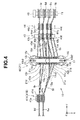
- FIG. 4 in the top view, the pulley 11 in which the rotating bodies 9u, 9d, 91, and 9r are arranged is shown with positions thereof shifted in the right direction in the figure from the fourth guide roller set 44 (which overlaps the pulley 11 in the top view) to show the traveling routes of the bending wires 8u, 8d, 81, and 8r.
- the traveling routes of the bending wires 8i extended from the distal end side of the insertion portion 2 to the proximal end side thereof are changed to a direction of the second guide roller set 42, which is arranged on a lower side in the axis direction of the manipulator 5, by a first guide roller sets 41A and 41B arranged in the grasping portion 3a.
- the traveling routes of the bending wires 8i passed through the second guide roller set 42 are further changed to a direction of the rotating body 9 of the pulley 11 by the third guide roller set 43.
- the traveling routes of the bending wires 8i passed through the rotating body 9 are changed to a direction of the third guide roller set 42.
- the bending wires 8i passed through the third guide roller set 42 pass through the guide roller set 21 coaxially provided with the third guide roller set 42.
- the bending wires 8i respectively come into contact with the wire guides 15i having a shape close to a substantial semispherical shape forming the operation force amount adjusting portion and respective rear ends of the bending wires 8i are fixed to the wire fixing portions 13i2 provided at cross-shaped end portions of the hanging arm 13 provided at the proximal end of the manipulator 5.
- Fig. 7 serving as an explanatory diagram close to Fig. 5
- the wire guide 15d in an opposite direction of the wire guide 15u is indicated by a broken line to make it easy to distinguish a difference between a case in which the wire guide 15d is provided and a case in which the wire guide 15d is not provided.
- the first guide roller sets 41A and 41B are arranged adjacent to each other along a direction (a Z direction) substantially parallel to the axis direction of the manipulator 5.
- Each of the first guide roller sets 41A and 41B rotatably supports two guide rollers 41u and 41d or 41l and 41r with a roller shaft 41p.
- the bending wires 8u, 8d, 81, and 8r are guided to the guide rollers 42u and 42d and 421 and 42r of the guide roller set 42, which are arranged on the proximal end side of the manipulator 5, by the guide rollers 41u and 41d and 41l and 41r.
- the respective guide rollers 42i of the guide roller set 42 are rotatably supported by a common roller shaft 42p together with guide rollers 21i of the guide roller set 21.
- the respective bending wires 8i the traveling routes of which are changed by the respective guide rollers 42i, pass through respective guide rollers 43i rotatably supported by a roller shaft 43p and are guided to the elastic rotating bodies 9i having a C-ring shape pivotably arranged in an outer circumference of the pulley 11.
- the rotating bodies 9i pivotably arranged in the outer circumference of the pulley 11 rotated by the motor 12 are in a loosely fit state in which there are slight gaps between the rotating bodies 9i and an outer circumferential surface of the pulley 11 to prevent a friction force from acting.
- a diameter of the rotating bodies 9i is reduced by a traction force amount (a traction force) of the towing.
- the rotating bodies 9i change to a state in which inner circumferential surfaces of the rotating bodies 9i come into contact with the outer circumferential surface of the pulley 11 and a friction force acts.
- the rotating bodies 9i rotate together with the pulley 11 in a direction in which the bending wires 8i are towed and assist(support) a towing action for the bending wires 8i.
- the rotating bodies 9i are formed in a C-ring shape having a cutout 9c, which is formed by cutting out one place in the circumferential direction in an annular shape, to be easily reduced in diameter when the bending wires 8i are towed.
- the respective bending wires 8i wound around the rotating bodies 9i about once are arranged on a lower side along the Z direction of the rotating bodies 9i.
- the traveling routes of the bending wires 8i are changed by guide rollers 44i rotatably supported by a roller shaft 44p.
- the respective bending wires 8i the traveling routes of which are changed by the guide rollers 44i, passes through the respective guide rollers 21i rotatably supported by the roller shaft 41p and the traveling routes thereof are changed.
- the bending wires 8i reach the wire fixing portions 13i2 in the hanging arms 13i.
- the bending wires 8i extending from the guide rollers 21i to the wire fixing portions 13i2 come into contact with curved surfaces of the wire guides 15i, which are attached near the wire fixing portions 13i2 in the hanging arms 13i, in the traveling routes immediately before the bending wires 8i reach the wire fixing portions 13i2.
- Fig. 6 shows a schematic shape of the wire guide 15u in which a contact portion 17c is formed by a projecting surface 17.
- shapes of the other wire guides 15d, 151, and 15r are the same as the shape of the wire guide 15u.
- the wire guide 15u having rigidity is divided into two along a surface passing near a center of a member having a shape close to an ellipsoid (including a sphere).
- the projecting surface 17 is formed by swelling an outer surface of one end portion in a major axis or minor axis direction of the wire guide 15u.
- a shape viewed from a side direction orthogonal to a portion where the projecting surface 17 is provided is a fan shape as shown in Fig. 5 and the like.
- a concave portion 17a for receiving bent end portions of the hanging arms 13i is provided near an upper surface on the projecting surface 17 in the wire guide 15u.
- a screw hole 17b is formed near a substantial center in a longitudinal direction of the projecting surface 17 such that the longitudinal direction on the upper surface formed as a plane comes into contact with bottom surfaces of the hanging arms 13i and can be attached (fixed) to the hanging arms 13i.
- an alternate long and two short dashes line indicates a state in which the bent end portions of the hanging arms 13i are housed in the concave portion 17a and a vicinity of a hand side end portion of the bending wire 8u comes into contact with the projecting surface 17 to form the contact portion 17c.
- the contact portion 17c moves according to a tilting angle of the manipulator 5. More strictly, the contact portion 17c, with which the vicinity of the hand side end portion of the bending wire 8u actually comes into contact, is a linear range along an extending direction of the bending wire 8u. The range changes according to the tilting angle of the manipulator 5.
- An operation force amount necessary for tilting operation of the manipulator 5 can be adjusted by an acting position 17d where a traction force acts on the bending wire 8u in the contact portion 17c as explained below.
- the acting position 17d where the traction force acts on the bending wire 8u in the contact portion 17c can also be represented as a position with which the bending wires 8i functioning as the traction member come into contact at a largest distance from a rotation axis in the contact portion 17c with which the bending wires 8i come into contact.
- an end portion on a lower end side in the linear range of the contact portion 17c is the acting position 17d.
- long holes 18 are provided along a longitudinal direction thereof to make it possible to adjust an attaching position of the wire guide 15u to a longitudinal direction of the long holes 18.
- the projecting surface 17 adjacent to a lower side of the concave portion 17a comes to be a contact surface or the contact portion 17c that comes into contact with the bending wires 8i.
- a position where the wire guide 15 is attached in the longitudinal direction of the hanging arms 13i is changed within a range of length of the long holes 18 attached to the hanging arms 13i. Consequently, it is possible to easily adjust an operation force amount by changing a distance to the acting position 17d of the contact portion 17c in the wire guides 15i, with which the hand side end portions of the bending wires 8i come into contact from the universal joint 14 when the manipulator 5 is tilted and which transmits an operation force amount by the tilting operation of the manipulator 5 as a traction force (a traction force amount).
- the operator places a finger of the hand grasping the grasping portion 3 a in the finger rest portion 5b of the manipulator 5 to tilt the shaft portion 5a of the manipulator 5. Consequently, the manipulator 5 tilts with a rotation center (a tilting center) set in a position where the manipulator 5 is pivotably supported by the universal joint 14 functioning as a bearing with respect to the up-down and left-right directions.
- a rotation center a tilting center
- a hanging arm 13j (j represents a specific hanging arm corresponding to the tilting of the upper end side of the manipulator 5) at the lower end side corresponding to the tilting of the upper end side of the manipulator 5 also tilts.
- a bending wire 8j is towed.
- a rotating body 9j around which the bending wire 8j is wound is reduced in diameter by the towed bending wire 8j.
- the rotating body 9j comes into contact with a pulley 11j on an inner side thereof (which transmits a rotating force of the motor 12).
- a friction force acts on the rotating body 9j and the pulley 11j and moves the bending wire 8j in a rotating direction of the pulley 11j.
- the bending portion 2b to which a distal end of the bending wire 8j is fixed, can be bent in a bending direction corresponding to operation of tilting of the manipulator 5.
- an operation force amount in tilting the manipulator 5 can be adjusted by changing a distance in which a traction force amount for traction acts on the bending wires 8i.
- the operation force amount can be adjusted by changing the distance from a distance a 0 (a first distance) in which a traction force amount acts on the hand side end portions of the bending wires 8i according to the tilting operation of the manipulator 5 when the wire guides 15i are not provided to a distance a (a second distance) in which the traction force acts when the wire guides 15i are provided.
- the endoscope 1 in the present embodiment having such a configuration is characterized by including the insertion portion 2 including the bending portion 2b, the bending wires 8i functioning as the traction member for bending the bending portion 2b through traction, the operation portion 3 provided at the proximal end of the insertion portion 2 and provided with the operation input portion 10 for performing an operation input for bending the bending portion 2b, the manipulator 5 including the hanging arms 13i functioning as the coupling members configuring the operation input portion 10 and provided to correspond to the bending direction of the bending portion 2b to which the traction member is coupled, the manipulator 5 pivoting around the rotating shaft pivotably supported by the universal joint 14 provided in the operation portion 3 according to tilting operation for performing the operation input and towing the traction member in the tilting direction, and the operation force amount adjusting portion configured to act on the traction member according to the tilting operation of the manipulator 5 and adjust an operation force amount necessary for the tilting of the manipulator 5.
- the operation force amount adjusting portion can be configured by the wire guides 15i including the projecting surface 17 forming the contact portion 17a that brings the operation force amount adjusting portion into contact with the traction member extending from the coupling member and transmits an operation force amount by the tilting of the manipulator 5 to the traction member and configured to adjust an operation force amount necessary for the tilting of the manipulator 5 by changing the first distance a 0 between the position where the traction member is coupled in the coupling member and the rotating shaft to the second distance a between the acting position 17d where the traction force acts on the traction member in the contact portion 17c and the rotating shaft simultaneously with the tilting of the manipulator 5.
- the operation force amount adjusting portion instead of configuring the operation force amount adjusting portion with the wire guides 15i configured to change the first distance a 0 to the second distance a between the acting position 17d in the contact portion 17c and the rotating shaft and adjust the operation force amount necessary for the tilting of the manipulator 5, it is also possible to configure the operation force amount adjusting portion including springs 51i provided in the manipulator 5 and functioning as elastic bodies for elastically urging the traction member extending from the coupling member with respect to the tilting of the manipulator 5 and configured to adjust the operation force amount necessary for the tilting of the manipulator 5 by elastically changing, with the elastic member, an acting direction of a traction force acting on the traction member extending from the coupling member.
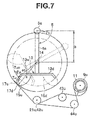
- Fig. 7 is a side view viewed from the same side direction as Fig. 5 .
- an explanatory diagram is shown in which, when the manipulator 5 is tilted in a state in which the manipulator 5 is viewed from a side direction perpendicular to a plane including the shaft portion 5a of the manipulator 5 in a neutral position state and the hanging arms 13u and 13d of the manipulator 5, the manipulator 5 tilts with a rotation center or a rotation axis set in a position pivotably supported by the universal joint 14 in the shaft portion 5a of the manipulator 5.
- a guide roller related to the upward direction in the guide roller set indicated by sign 42 or the like is shown (the same applies in modifications and embodiments explained below).
- an operation force amount obtained when the operator places a finger in the finger rest portion 5b of the manipulator 5 and tilts the shaft portion 5a in the upward direction in order to bend the bending portion 2b in the upward direction is represented as Fu
- a distance from a center of the universal joint 14 to the acting position (or the contact portion acting position) 17d where the vicinity of the hand side end portion of the bending wire for upward direction 8u comes into contact in the contact portion 17c and a traction force amount Tu for towing the bending wire 8u for upward direction acts in the wire guide for upward direction 15u is represented as a
- a distance (also referred to as operation side distance) from the center of the universal joint 14 to a center of the finger rest portion 5b is represented as b.
- a distance from the center of the universal joint 14 to (a terminal end position of) the wire fixing portion for upward direction 13u2, which is a position where a traction force amount Tu 0 for towing the bending wire for upward direction 8u in the case in which the wire guide for upward direction 15u is not provided is represented as a 0 .
- a circle indicated by a solid line indicates a track drawn by the acting position 17d when the manipulator 5 is tilted.
- a circle indicated by an alternate long and two short dashes line indicates a track drawn by the wire fixing portion for upward direction 13u2 when the manipulator 5 is tilted.
- the angle ⁇ is larger than the angle ⁇ 0 in a tilting range (a bending range).
- ⁇ (and ⁇ 0 ) is smaller than 90°. Therefore, sin ⁇ > sin ⁇ 0 .
- an operation force amount necessary in the tilting operation to bend the bending portion 2b near the neutral position may be small (the tilting operation for the bending can be performed with a small operation force amount). Therefore, when small bending is about to be performed, it is necessary to perform the tilting operation with a fine operation force amount.
- the distance a larger than the distance a 0 when the wire guides 15i are not provided is set. Therefore, it is possible to perform the same tilting operation with a rougher operation force amount. It is possible to reduce a burden on the operator with a simple configuration and improve operability. Even when the operation portion 3 is reduced in size by, for example, reducing a length of the shaft portion 5a of the manipulator 5, it is possible to provide the endoscope 1 that can adjust an operation force amount. Further, by increasing an operation force amount near the neutral position (necessary for the tilting operation for bending the bending portion 2b), it is possible to prevent the bending portion 2b from being bent by careless tilting operation.
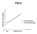
- Fig. 8 shows a characteristic chart showing a relation of an operation force amount (with respect to a bending angle or a tilting angle) necessary when the bending portion 2b in the present embodiment is bent in the upward direction.
- a dotted line indicates a characteristic in the case of the related art in which the wire guide 15 is not provided.
- a bending range a tilting range Wa near the neutral position
- the operator needs to finely adjust an operation force amount as explained above.
- the characteristic requires a larger operation force amount, it is possible to smoothly set the bending angle to a desired bending angle through tilting operation with a rougher operation force amount.
- Figs. 7 and 8 are explained in the case of the tilting operation for performing the bending in the upward direction. However, substantially the same action and effects are obtained in cases of the other directions.
- the shape of the wire guides 15i is one example and may be a shape different from the shape shown in the figure.
- the guide wires 15u, 15d, 151, and 15r are provided in both of the up-down direction and the left-right direction.
- the guide wires 15u and 15d or 151 and 15r may be provided only in at least one of the up-down direction and the left-right direction.
- Fig. 9 shows a configuration of a peripheral portion of an operation input portion 10B in a first modification of the first embodiment.
- resistance portions 31i functioning as resistance in towing the bending wires 8i are provided halfway in the traveling routes of the bending wires 8i to form an operation force amount adjusting portion, whereby functions similar to the functions in the first embodiment are provided.
- the resistance portion 31i is configured by guide members 32i attached to the bending wires 8i, pairs of guide rollers 33i and 34i arranged to sandwich the bending wires 8i on the traveling routes of the bending wires 8i on which the guide members 32i are towed and moved (by tilting operation of the manipulator 5), and springs 35i configured to urge the one guide rollers 34i to the other guide rollers 33i side.
- One ends of the springs 35i are fixed to an inner wall of the operation portion 3 or a frame for retaining the operation input portion 10B. The other ends are fixed to bearings of the guide rollers 34i.
- the guide members 32i are set in a shape in which thickness on a distal end side in a direction of traction movement of the bending wires 8i (in Fig. 9 , the left direction) is large and decreases toward a rear end side.
- Fig. 10 shows a state in which the manipulator 5 in the neutral position state in Fig. 9 is tilted to the upward direction (tilted in a clockwise direction in Fig. 9 ) to be bent in the upward direction of the bending portion 2b.
- This modification is the same as a configuration in which the resistance portions 31i are provided in the configuration in which the wire guides 15i are not provided in the first embodiment.
- a guide member for upward direction 32u moves together with the movement of the bending wire for upward direction 8u. As shown in Fig. 10 , the guide member for upward direction 32u is located between the pair of guide rollers 33u and 34u. In this state, the guide member for upward direction 32u passes between the guide rollers 33u and 34u while being pressed by the pair of guide rollers 33u urged by the spring for upward direction 35u.
- the guide member 32u functions as resistance for traction movement of the bending wire for upward direction 8u.
- an operation force amount necessary in tilting the manipulator 5 is increased.
- resistance against traction movement is large in a state in which the guide member 32u nearly starts to come into contact with the guide rollers 33u and 34u. Thereafter, the resistance decreases according to the traction movement.
- the guide members 32i may be formed in a rotation-symmetrical shape around the bending wires 8i.
- This modification may be applied to the first embodiment as well.
- this modification is applied to the first embodiment, there is an effect that adjustment of an operation force amount can be performed in a wider range.
- Shapes on a distal end side and a rear end side in the direction of traction movement shown in Fig. 9 may be reversed to set thickness on the distal end side in the direction of traction movement to be small and increase toward the rear end side.
- the operation force amount adjusting portion is explained that adjusts (sets) the operation force amount to be large in the bending range close to the neutral position or the tilting range for performing operation of bending.
- the present invention is not limited to such a case.
- an operation force amount adjusting portion may be formed that reduces an operation force amount on a bending range side close to the neutral position.
- Fig. 11 shows a configuration of a peripheral portion of an operation input portion 10C in a second modification of the first embodiment.
- an operation force amount adjusting portion 53C is formed using the springs 51i and the guide rollers 52i coupled to the manipulator 5 instead of providing the wire guides 15i in the first embodiment.
- the operation force amount adjusting portion 53C is formed that adjusts an operation force amount by changing, with respect to tilting operation of the manipulator 5, using an elastic force of the springs 51 i, direction of a traction force acting on the hand side end portions of the bending wires 8i functioning as the traction member.
- a projecting piece 54 projecting downward piercing through a (not-shown) hole of the hanging arm 13 is provided in the manipulator 5.
- One ends of the springs 51i are fixed to a lower end of the projecting piece 54.
- the one ends of the springs 51i functioning as elastic bodies or elastic members are fixed to the proximal end or ends on the proximal end side of the manipulator 5.
- the projecting piece 54 may be projected from the hanging arm 13.
- the one ends of the springs 51i may be fixed to, for example, a center position of a bottom surface of the hanging arm 13 functioning as a coupling member without providing the projecting piece 54.
- the other ends of the springs 51i are attached to rotating shafts of the guide rollers 52i configured to changeably hold the traveling routes of the bending wires 8i extended from the guide rollers 21i to the wire fixing portions 13i2 (the guide roller set 21 side) of the hanging arm 13.
- the rotating shafts of the guide rollers 52i are movably held in a state in which the rotating shafts pulled to a lower end side of the projecting piece 54 (to which the one ends of the springs 51i are fixed) with an elastic force by the springs 51i.
- the springs 51i urge the guide rollers 21 i, to which the other ends of the springs 51i are fixed, to be elastically towed to thereby urge the bending wires 8i in positions where the bending wires 8i are movably held by the guide rollers 21i to be towed to the one end side of the spring 51i.
- springs 51u and 51d and guide rollers 52u and 52d are shown.
- not-shown springs 511 and 51r and guide rollers 521 and 52r are provided in a vertical direction of a paper surface.
- the spring 51u extends because of an increased traction force amount.
- the bending wire for upward direction 8u extending from the guide roller for upward direction 21u nearly linearly extends from a bent state with an elastic force of the spring 51u to reach the wire fixing portion for upward direction 13u2. Note that, in Fig. 12 , only members related to the bending wire for upward direction 8u are shown.
- the operation force amount adjusting portion 53C is formed to adjust, near the neutral position, with the springs 51i, an operation force amount such that the traction force amount for towing the bending wires 8i acts in a different direction (from the related art in which the springs 51i and the guide rollers 52i are not provided), the springs 51i extend as the traction force amount t increases, and an operation force amount close to an operation force amount in the related art is obtained.
- the operation force amount adjusting portion 53C is set to a characteristic for making it possible to greatly change, near the neutral position, a direction in which a traction force or a traction force amount acts (from the case of the related art) and bend the bending portion 2b with a smaller operation force amount than the case of the related art.
- a traction force amount acting on (the hand side end portion of) the bending wire for upward direction 8u when the manipulator 5 is tilted is Tu along a direction near a horizontal direction of the paper surface as bending wire for upward direction 8u is pulled by the spring 51u in this modification.
- the traction force is Tu 0 along a direction indicated by a dotted line.
- Equation (4) is approximately the following Equation (5).
- an operation force amount is adjusted to be sin ⁇ (more accurately, sin ⁇ /sin ⁇ 0 ) times as large as an operation force amount in the related art by changing a direction in which a traction force amount acts.
- a schematic characteristic of an operation force amount with respect to a bending angle by this modification is indicated by a solid line and a schematic characteristic in the case of the related art is indicated by a dotted line.
- tilting operation is performed with an operation force amount smaller than an operation force amount in the related art.
- Fig. 14 shows a top view ( Fig. 14(A) ) and a side view ( Fig. 14(B) ) of a hanging arm coupled to a lower end of a manipulator in a third modification of the first embodiment.
- an integrated wire guide 71 is attached to the hanging arm 13 as shown in Fig. 14 .
- wire fixing portions 73i configured to fix (attach) the hand side end portions of the respective bending wires 8i to a vicinity of an upper surface end portion facing an inner side of the long grooves 72i in the wire guide 71 are provided.
- a size extending to a curved surface in the downward direction is set larger than a size in the horizontal direction.
- a distance extending from the rotation center to the wire fixing portions of the hanging arms 13i is a'. Therefore, a 0 > a'.
- the bending wire for upward direction 8u extended from the guide roller 21u is fixed to a position of a hand side end portion 73u as indicated by a solid line.
- an alternate long and two short dashes line indicates a case in which the wire guide 71 is not provided and the bending wire for upward direction 8u is fixed to a wire fixing portion of the hanging arm for upward direction 13u.
- a radius of an alternate long and short dash line indicates that the distance a 0 from the rotation center to the wire fixing portion of the hanging arm for upward direction 13u is set as a radius.
- members related to bending in the upward direction are shown. However, the same substantially applies in the case of bending in the downward direction. The same substantially applied in the case of the left-right direction.
- this modification has a characteristic closer to the characteristic chart of Fig. 13 . That is, it is possible to reduce an operation force amount in the case of a small bending range. According to this modification, it is possible to form an operation force amount adjusting portion that can easily adjust an operation force amount. Note that, although the integrated wire guide 71 is used in this modification, the wire guide 71 may be formed by a plurality of wire guides without being integrated.
- the bending portion 2b can be bent in any bending direction in an up-down direction and a left-right direction by tilting operation by a finger.
- a bending direction of bending in the up-down direction and the left-right direction is set by giving a difference to magnitudes of operation force amounts, whereby it is possible to easily distinguish (or sense) the bending direction with a finger for performing the tilting operation. Therefore, it is possible to improve operability for an operator.
- an operation force amount necessary in performing tilting operation for bending the bending portion 2b is set to be different in the up-down direction and the left-right direction to be easily distinguished (or sensed).
- Fig. 15(A) shows a side view of a peripheral portion of an operation input portion 10D in which the manipulator 5 in a neutral position state is viewed from a longitudinal direction of the hanging arm for left direction 131.
- Fig. 15(B) shows a side view of a peripheral portion of an operation input portion 10E in which the manipulator 5 in the neutral position state is viewed from a longitudinal direction of the hanging arm for upward direction 13u.
- a wire guide 61 shown in Fig. 15 is provided instead of the four wire guides 15i in the first embodiment to form an operation force amount adjusting portion 53E functioning as a direction adjusting member set (adjusted) to be capable of sensing a magnitude of an operation force amount in the an up-down direction and the left-right direction.
- the wire guides 15i are respectively provided in the portions of the four hanging arms 13i.
- the integral wire guide 61 is attached to the bottom surface of the hanging arm 13.
- the wire guide 61 is convex in the downward direction of the shaft portion 5a as shown in Fig. 15(A) and is formed in a curved surface shape formed along a fixed distance r from a rotation center of a bearing in the shaft portion 5a.
- the wire guide 61 is convex in the downward direction of the shaft portion 5a as shown in Fig. 15(B) but, near an end portion of the hanging arm 13, is formed in a curved surface shape including projecting surfaces 611 and 61r projecting to an outer side at the distance r (e.g., the projecting surface 61r has the distance r').
- curved surface shape portions shown in Figs. 15(A) and 15(B) are respectively acting positions of a contact portion with which the hand side end portions of the bending wires 8i come into contact. an operation force amount is determined according to the acting positions of the contact portion.
- Portions of the projecting surfaces 611 and 61r have a shape close to the shape of the projecting surface of the wire guides 151 and 15r in the first embodiment.
- a function of the portions is similar to the functions of the projecting surfaces in the first embodiment.
- a curved surface between the projecting surfaces 611 and 61r i.e., a curved surface equivalent to the curved surface in the case of the up-down direction
- a distribution of an operation force amount obtained when tilting operation is performed in the left-right direction and the up-down direction in the present embodiment has a characteristic like a characteristic chart shown in Fig. 16(A) .
- a relatively narrow bending range Wa as shown in Fig. 16(A) an operation force amount in the left-right direction is larger than an operation force amount in the up-down direction. Therefore, the operator can distinguish (sense), from a difference between the operation force amounts, with operation by a finger, for bending operation in which bending direction of the left-right direction and the up-down direction the tilting operation is performed.
- a shape of the acting position of the contact portion with which the hand side end portions of the bending wires 8i of the wire guide 61 come into contact is formed to be different in the up-down direction and the left-right direction. Therefore, the operator can easily distinguish or sense, with a finger used for operation, in which direction of the an up-down direction and the left-right direction bending operation is performed. Besides, as in the first embodiment, it is also possible to adjust a magnitude of an operation force amount with the wire guide 61.
- a characteristic obtained by interchanging the characteristic shown in Fig. 16 in the up-down direction and the left-right direction may be set.
- a structure may be adopted in which the projecting surfaces 611 and 61r shown in Fig. 15(B) are provided on the wire guide 61 side shown in Fig. 15(A) and the projecting surfaces 611 and 61r are not provided on the wire guide 61 side shown in Fig. 15(B) .
- an input operation portion 10F that makes it easy to sense operation force amounts in the up-down direction and the left-right direction may be formed by applying a configuration close to the second modification of the first embodiment (the structure in which the springs 51i are used shown in Fig. 11 ) as shown in Fig. 17 referred to below.
- a direction different from a direction (a direction close to horizontal in Fig. 11 ) in which the traction force amount Tu acts in the up-down direction shown in Fig. 11 is set by the springs 511 and 51r.
- An angle (or a supplementary angle) formed by a direction of the distance a and a direction in which the traction force amount Tu acts is indicated by ⁇ 1.
- the angle ⁇ formed by the direction extending from the center of the universal joint 14 to the wire fixing portion 13u2 and the direction of the traction force amount Tu is set.
- the angle 81 larger than the angle ⁇ is set. That is, 8 ⁇ ⁇ 1, where ⁇ 1 ⁇ ⁇ 0 and sin ⁇ 1 ⁇ sin ⁇ 0 .
- a direction of a traction force amount acting on the hand side end portions of the bending wires 8i is changed by an elastic force of the springs 51i to form an operation force amount adjusting portion 53F configured to adjust an operation force amount in operating the manipulator 5.
- a distribution of an operation force amount in the case of Fig. 17 is substantially the same as the characteristic chart of Fig. 16 .
- operation force amounts may be set to be different.
- the operation force amounts are set in that way, when the tilting operation in the up-down direction or the left-right direction is performed, it is also possible to grasp a tilting direction from a difference in a magnitude of an operation force amount.
Landscapes
- Life Sciences & Earth Sciences (AREA)
- Health & Medical Sciences (AREA)
- Surgery (AREA)
- Engineering & Computer Science (AREA)
- Biophysics (AREA)
- Medical Informatics (AREA)
- Nuclear Medicine, Radiotherapy & Molecular Imaging (AREA)
- Optics & Photonics (AREA)
- Pathology (AREA)
- Radiology & Medical Imaging (AREA)
- Veterinary Medicine (AREA)
- Biomedical Technology (AREA)
- Heart & Thoracic Surgery (AREA)
- Physics & Mathematics (AREA)
- Molecular Biology (AREA)
- Animal Behavior & Ethology (AREA)
- General Health & Medical Sciences (AREA)
- Public Health (AREA)
- Mechanical Engineering (AREA)
- Instruments For Viewing The Inside Of Hollow Bodies (AREA)
- Endoscopes (AREA)
- Manipulator (AREA)
Abstract
Description
- The present invention relates to an endoscope in which a bending portion is driven to be bent.
- In recent years, an endoscope has been widely used in a medical field and an industrial field. A bendable bending portion is provided on a distal end side of an insertion portion in the endoscope to make it easy to insert the endoscope into even a bent region.
- The bending portion is coupled to an operation input portion for bending provided on a proximal end side of the insertion portion via a bending operation wire functioning as a traction member inserted through the insertion portion. An operator can tow the bending operation wire and bend the bending portion by pivoting a bending knob configuring the operation input portion.
- When the bending portion is driven to be bent manually by the operator, a large operation force amount is necessary. Therefore, there is proposed an endoscope of an electric assist system in which a traction member is towed via electric driving means by tilting operation of a manipulator such as an operation lever or a joystick configuring an operation input portion.
- For example, Japanese Patent Application Laid-Open Publication No.
2003-325437 - In this way, in the case of the endoscope of the electric assist system, compared with the manual bending of the bending portion, it is possible to bend the bending portion with a small operation force amount by the tilting operation of the manipulator. Such a conventional art endoscope, however, is disadvantageously hardly applicable as-is to a medical endoscope desirably operated with the fingers of a hand grasping (a grasping portion of) an operation portion.
- For example, decreasing the length of the manipulator's shaft portion so as to allow the fingers of the hand grasping the grasping portion to reach the manipulator leads to its improved operability but causes change in its operation force amount. Such size reduction hinders setting the operation force amount necessary to bend the bending portion to an appropriate operation force amount that permits easy operation. There are also situations where it is desired to increase the operation force amount of the manipulator when close to the neutral position to prevent inadvertent bending of the bending portion or to allow for its fine bending operation even when close to the neutral position.
- These reasons lead to the need for size-reduced endoscopes, such as medical endoscopes, having high operability and allowing the operator to adjust the operation force amount to an appropriate operation force amount.
- The present invention was made in view of the above circumstances, and an objective of the present invention is to provide an endoscope that, even if reduced in size, allows for adjustment of the operation force amount.
- An endoscope according to an aspect of the present invention includes: an insertion portion including a bending portion; a traction member for bending the bending portion through traction; an operation portion provided at a proximal end of the insertion portion and provided with an operation input portion configured to perform an operation input for bending the bending portion; a manipulator configuring the operation input portion, the manipulator including a coupling member which is coupled with the traction member and which is provided to correspond to a bending direction of the bending portion, the manipulator towing the traction member in the tilting direction by pivoting around a rotating shaft by a bearing provided to the operation portion through a tilting operation for performing the operation input; and an operation force amount adjusting portion configured to act on the traction member according to the tilting of the manipulator, and to adjust an operation force amount necessary for tilting the manipulator.
-
-
Fig. 1 is a perspective view showing an endoscope in a first embodiment of the present invention. -
Fig. 2 is a side view showing a configuration around an operation portion provided with an operation input portion in a state in which a side cover of an operation portion main body is grasped. -
Fig. 3 is a perspective view showing a configuration of the operation input portion including a manipulator or the like for towing a traction member. -
Fig. 4 is a top view showing the configuration of the operation input portion including the manipulator or the like for towing the traction member. -
Fig. 5 is a side view of the operation input portion shown inFig. 3 . -
Fig. 6 is a perspective view showing a schematic shape of a wire guide. -
Fig. 7 is an explanatory diagram of action in tilting the manipulator in an upward direction in a simplified form ofFig. 5 . -
Fig. 8 is a characteristic chart showing a relation of an operation force amount with respect to a bending angle. -
Fig. 9 is a diagram showing a schematic configuration of an operation input portion in a first modification of the first embodiment. -
Fig. 10 is a diagram showing a state in which the manipulator is tilted inFig. 9 . -
Fig. 11 is a diagram showing a schematic configuration of an operation input portion in a second modification of the first embodiment. -
Fig. 12 is a diagram showing a state in which the manipulator is tilted at a predetermined tilting angle or more inFig. 11 . -
Fig. 13 is a characteristic chart showing a relation of an operation force amount with respect to a bending angle. -
Fig. 14 is a diagram showing a schematic configuration of a peripheral portion of a manipulator in a third modification of the first embodiment. -
Fig. 15 is a side view showing a configuration near a manipulator in a second embodiment of the present invention. -
Fig. 16 is a characteristic chart showing a distribution of an operation force amount obtained when a manipulator is tilted in a left-right direction and an up-down direction in the second embodiment. -
Fig. 17 is a diagram showing a schematic configuration of an operation input portion configured to perform tilting operation in a left-right direction in a modification of the second embodiment. - Embodiments of the present invention are explained below with reference to the drawings.
- As shown in
Fig. 1 , an endoscope 1 of the present invention is an endoscope of an electric assist system. The endoscope 1 includes anelongated insertion portion 2, anoperation portion 3 jointly provided to a proximal end of theinsertion portion 2, and auniversal cord 4 extending from a side portion of theoperation portion 3. - The
insertion portion 2 is formed by jointly providing, in order from a distal end side, a rigiddistal end portion 2a, abending portion 2b bendable in up-down and left-right directions, and aflexible tube portion 2c having flexibility and formed long. An illumination window and an observation widow are provided in thedistal end portion 2a. Illumination light is emitted from the illumination window. A not-shown image pickup apparatus configured to pick up an image of an illuminated region is provided in the observation window. - The
operation portion 3 includes agrasping portion 3a jointly provided to a proximal end (a rear end) of theinsertion portion 2 and an operation portionmain body 3b jointly provided to a proximal end of thegrasping portion 3a. A longitudinal axis of thegrasping portion 3a and an insertion axis of theinsertion portion 2 are in a coaxial or parallel positional relation. - An operation input portion 10 (see
Fig. 2 ) configured to perform an operation input for bending thebending portion 2b is provided on an inner side covered with acover member 7 in the operation portionmain body 3b. A bar-like shaft portion 5a of amanipulator 5 configuring theoperation input portion 10 projects from thecover member 7. Themanipulator 5 is provided to project in a Z-axis direction orthogonal to a longitudinal axis (a Y-axis direction inFig. 2 ) of the operation portionmain body 3b (or the operation portion 3) from a manipulator projection port, which is an opening, provided on one surface of the operation portionmain body 3b. Note that thecover member 7 water-tightly closes the manipulator projection port and closely attaches to theshaft portion 5a of the manipulatormain body 5 and is formed of a flexible member such as rubber for holding themanipulator 5 to enable tilting operation of themanipulator 5. - The longitudinal axis of the operation portion
main body 3b and the longitudinal axis of thegrasping portion 3a are in a coaxial or parallel positional relation. - According to tilting operation including a tilting direction in the up-down direction and the left-right direction and a tilting angle of the
manipulator 5 by an operator such as a surgeon, bending operation wires (hereinafter abbreviated as bending wires) 8u, 8d, 81, and 8r explained below functioning as a traction member inserted through theinsertion portion 2 are towed and slacked. Thebending portion 2b is configured to be able to be bent in an upward direction, a downward direction, a left direction, and a right direction on a towed side of the bending wires and arbitrary directions among the directions. - In the present embodiment, the
bending portion 2b is configured to be bendable in four directions of up, down, left, and right. According to the configuration, the present embodiment includes a traction member in the up-down direction and a traction member in the left-right direction. Themanipulator 5 has functions of a manipulator in the up-down direction that is tilted in the up-down direction and a manipulator in the left and right direction that is tilted in the left-right direction. The present invention is not limited to the configuration in which thebending portion 2b bends in the four directions of up, down, left, and right and may be a configuration in which thebending portion 2b bends only in the up-down direction or the left-right direction. The signs u, d, l, and r represent that the signs correspond to the up, down, left, and right directions, which are the bending directions of thebending portion 2b. In the following explanation, for example, asign 8u represents a bending wire for upward direction. The same applies to the other signs. - For example, in
rotating bodies - For example, when this applies to respective bending wires in the
bending wires - In an armor of the operation portion
main body 3b, besides themanipulator 5, an air feeding andwater feeding button 6b and a suction button 6c are provided to project to a position set in advance as shown inFig. 2 . Achannel insertion port 6d communicating with a treatment instrument channel (not shown in the figure) is provided near the proximal end of the graspingportion 3a. - When the operator grasps the grasping
portion 3a of theoperation portion 3 with a left hand in the same manner as grasping a conventional endoscope, themanipulator 5 is provided in a position where themanipulator 5 can be operated to be tilted by a thumb of the grasping hand of the operator and the air feeding andwater feeding button 6b and the suction button 6c are provided in a position where the buttons can be operated by a finger other than the thumb of the grasping hand of the operator. - Next, a configuration of the
operation input portion 10 is explained with reference toFigs. 2 to 6 . Distal ends of the bending wires 8i inserted through along the respective directions of up-down and left-right in theinsertion portion 2 are fixed to a not-shown bending piece at a most distal end configuring the bendingportion 2b. - Rear end sides of the bending wires 8i inserted through the
insertion portion 2 are coupled to a hangingarm 13 functioning as a coupling member provided at the proximal end of themanipulator 5 through a guide roller set or the like configuring theoperation input portion 10. - The
operation input portion 10 mainly includes the fourbending wires rotating bodies pulley 11, amotor 12, themanipulator 5 coupled to the hangingarm 13, a plurality of guide roller sets 41, 42, 43, and 44 and a guide roller set 21 configured to change traveling routes of the fourbending wires operation portion 3, andwire guides - The
manipulator 5 includes the bar-like shaft portion 5a and afinger rest portion 5b that is formed in a spherical shape at an end portion on a terminal end side of theshaft portion 5a and against which a finger of the operator is pressed. Auniversal joint 14 forming a bearing configured to rotatably support theshaft portion 5a according to up-down and left-right tilting with respect to themanipulator 5 is provided halfway in theshaft portion 5a. A hanging frame or the hangingarm 13 having a cross shape and extending in the four directions in a plane orthogonal to theshaft portion 5a is coupled and fixed to an end on a proximal end side (a proximal end) of theshaft portion 5a. - At terminal end portions of hanging
arms arm 13, wire fixing portions 13u2, 13d2, 13l2, and 13r2 (seeFig. 3 , etc.), formed by, for example, hole portions, configured to respectively fix (attach) respective proximal ends of thebending wires - In the present embodiment, near the wire fixing portions 13i2 of the hanging arms 13i, wire guides 15i forming an operation force amount adjusting portion configured to adjust an operation force amount in tilting the
manipulator 5 and bending the bendingportion 2b are provided. - Note that the
manipulator 5 and the hangingarm 13 functioning as the coupling member jointly provided to the proximal end side of themanipulator 5 may be defined as a manipulator or may be defined as separate members. - In the present embodiment, the
pulley 11 and themotor 12 are arranged in the operation portionmain body 3b in a positional relation in which each of a longitudinal axis of thepulley 11 and a driving axis of themotor 12 is orthogonal to the longitudinal axis of the operation portion 3 (the graspingportion 3 a) and such that the longitudinal axis of thepulley 11 and the driving axis of themotor 12 are orthogonal to an axis direction of themanipulator 5 in a state of a neutral position (a neutral state position) as well. Thepulley 11 and themotor 12 are separate bodies. Thepulley 11 and themotor 12 are disposed, for example, in a position parallel to the axis direction of the manipulator 5 (inFig. 2 , adjacent in the up-down direction near a right end in the operation portionmain body 3b). - A motor side gear (not shown) is provided in a shaft (not shown) of the
motor 12. A pulley side gear 49 (seeFig. 4 ) configured to mesh with the motor side gear is provided in a position set in advance of thepulley 11. Rotation of themotor 12 is transmitted to thepulley 11 via the motor side gear and thepulley side gear 49, whereby themotor 12 rotates. Then, thepulley 11 also rotates. - Note that in
Figs. 3 and4 , themotor 12 is not shown. InFig. 4 , portions of the hanging arm forupward direction 13u and the hanging arm fordownward direction 13d of the hangingarm 13 are indicated by broken lines. InFig. 4 , in the top view, thepulley 11 in which therotating bodies pulley 11 in the top view) to show the traveling routes of thebending wires - The traveling routes of the bending wires 8i extended from the distal end side of the
insertion portion 2 to the proximal end side thereof are changed to a direction of the second guide roller set 42, which is arranged on a lower side in the axis direction of themanipulator 5, by a first guide roller sets 41A and 41B arranged in the graspingportion 3a. - The traveling routes of the bending wires 8i passed through the second guide roller set 42 are further changed to a direction of the
rotating body 9 of thepulley 11 by the third guide roller set 43. The traveling routes of the bending wires 8i passed through therotating body 9 are changed to a direction of the third guide roller set 42. - The bending wires 8i passed through the third guide roller set 42 pass through the guide roller set 21 coaxially provided with the third guide roller set 42. The bending wires 8i respectively come into contact with the wire guides 15i having a shape close to a substantial semispherical shape forming the operation force amount adjusting portion and respective rear ends of the bending wires 8i are fixed to the wire fixing portions 13i2 provided at cross-shaped end portions of the hanging
arm 13 provided at the proximal end of themanipulator 5. - Note that, in
Fig. 7 serving as an explanatory diagram close toFig. 5 , thewire guide 15d in an opposite direction of thewire guide 15u is indicated by a broken line to make it easy to distinguish a difference between a case in which thewire guide 15d is provided and a case in which thewire guide 15d is not provided. - As shown in
Figs. 3 to 5 , the first guide roller sets 41A and 41B are arranged adjacent to each other along a direction (a Z direction) substantially parallel to the axis direction of themanipulator 5. Each of the first guide roller sets 41A and 41B rotatably supports twoguide rollers roller shaft 41p. - The bending
wires guide rollers manipulator 5, by theguide rollers common roller shaft 42p together with guide rollers 21i of the guide roller set 21. - The respective bending wires 8i, the traveling routes of which are changed by the respective guide rollers 42i, pass through respective guide rollers 43i rotatably supported by a
roller shaft 43p and are guided to the elastic rotating bodies 9i having a C-ring shape pivotably arranged in an outer circumference of thepulley 11. - In a normal state, the rotating bodies 9i pivotably arranged in the outer circumference of the
pulley 11 rotated by themotor 12 are in a loosely fit state in which there are slight gaps between the rotating bodies 9i and an outer circumferential surface of thepulley 11 to prevent a friction force from acting. When the bending wires 8i wound around the rotating bodies 9i are towed, a diameter of the rotating bodies 9i is reduced by a traction force amount (a traction force) of the towing. The rotating bodies 9i change to a state in which inner circumferential surfaces of the rotating bodies 9i come into contact with the outer circumferential surface of thepulley 11 and a friction force acts. - In the state in which the friction force acts, the rotating bodies 9i rotate together with the
pulley 11 in a direction in which the bending wires 8i are towed and assist(support) a towing action for the bending wires 8i. As shown inFig. 3 and the like, the rotating bodies 9i are formed in a C-ring shape having acutout 9c, which is formed by cutting out one place in the circumferential direction in an annular shape, to be easily reduced in diameter when the bending wires 8i are towed. - The respective bending wires 8i wound around the rotating bodies 9i about once are arranged on a lower side along the Z direction of the rotating bodies 9i. The traveling routes of the bending wires 8i are changed by guide rollers 44i rotatably supported by a
roller shaft 44p. - The respective bending wires 8i, the traveling routes of which are changed by the guide rollers 44i, passes through the respective guide rollers 21i rotatably supported by the
roller shaft 41p and the traveling routes thereof are changed. The bending wires 8i reach the wire fixing portions 13i2 in the hanging arms 13i. - The bending wires 8i extending from the guide rollers 21i to the wire fixing portions 13i2 come into contact with curved surfaces of the wire guides 15i, which are attached near the wire fixing portions 13i2 in the hanging arms 13i, in the traveling routes immediately before the bending wires 8i reach the wire fixing portions 13i2.
-
Fig. 6 shows a schematic shape of thewire guide 15u in which acontact portion 17c is formed by a projectingsurface 17. Note that shapes of the other wire guides 15d, 151, and 15r are the same as the shape of thewire guide 15u. Thewire guide 15u having rigidity is divided into two along a surface passing near a center of a member having a shape close to an ellipsoid (including a sphere). The projectingsurface 17 is formed by swelling an outer surface of one end portion in a major axis or minor axis direction of thewire guide 15u. A shape viewed from a side direction orthogonal to a portion where the projectingsurface 17 is provided is a fan shape as shown inFig. 5 and the like. - A
concave portion 17a for receiving bent end portions of the hanging arms 13i is provided near an upper surface on the projectingsurface 17 in thewire guide 15u. For example, ascrew hole 17b is formed near a substantial center in a longitudinal direction of the projectingsurface 17 such that the longitudinal direction on the upper surface formed as a plane comes into contact with bottom surfaces of the hanging arms 13i and can be attached (fixed) to the hanging arms 13i. Note that an alternate long and two short dashes line indicates a state in which the bent end portions of the hanging arms 13i are housed in theconcave portion 17a and a vicinity of a hand side end portion of thebending wire 8u comes into contact with the projectingsurface 17 to form thecontact portion 17c. Thecontact portion 17c, with which the vicinity of the hand side end portion of thebending wire 8u actually comes into contact, moves according to a tilting angle of themanipulator 5. More strictly, thecontact portion 17c, with which the vicinity of the hand side end portion of thebending wire 8u actually comes into contact, is a linear range along an extending direction of thebending wire 8u. The range changes according to the tilting angle of themanipulator 5. An operation force amount necessary for tilting operation of themanipulator 5 can be adjusted by an actingposition 17d where a traction force acts on thebending wire 8u in thecontact portion 17c as explained below. Note that the actingposition 17d where the traction force acts on thebending wire 8u in thecontact portion 17c can also be represented as a position with which the bending wires 8i functioning as the traction member come into contact at a largest distance from a rotation axis in thecontact portion 17c with which the bending wires 8i come into contact. In the case ofFigs. 5, 6 , and7 , an end portion on a lower end side in the linear range of thecontact portion 17c is the actingposition 17d. - On the other hand, in the hanging arms 13i,
long holes 18 are provided along a longitudinal direction thereof to make it possible to adjust an attaching position of thewire guide 15u to a longitudinal direction of thelong holes 18. - When the wire guides 15i are attached to the hanging arms 13i, the projecting
surface 17 adjacent to a lower side of theconcave portion 17a comes to be a contact surface or thecontact portion 17c that comes into contact with the bending wires 8i. - A position where the wire guide 15 is attached in the longitudinal direction of the hanging arms 13i is changed within a range of length of the
long holes 18 attached to the hanging arms 13i. Consequently, it is possible to easily adjust an operation force amount by changing a distance to the actingposition 17d of thecontact portion 17c in the wire guides 15i, with which the hand side end portions of the bending wires 8i come into contact from the universal joint 14 when themanipulator 5 is tilted and which transmits an operation force amount by the tilting operation of themanipulator 5 as a traction force (a traction force amount). - The operator places a finger of the hand grasping the grasping
portion 3 a in thefinger rest portion 5b of themanipulator 5 to tilt theshaft portion 5a of themanipulator 5. Consequently, themanipulator 5 tilts with a rotation center (a tilting center) set in a position where themanipulator 5 is pivotably supported by the universal joint 14 functioning as a bearing with respect to the up-down and left-right directions. - In this case, according to the tilting of an upper end side of the
manipulator 5, a hanging arm 13j (j represents a specific hanging arm corresponding to the tilting of the upper end side of the manipulator 5) at the lower end side corresponding to the tilting of the upper end side of themanipulator 5 also tilts. According to the tilting of the hanging arm 13j, a bending wire 8j is towed. A rotating body 9j around which the bending wire 8j is wound is reduced in diameter by the towed bending wire 8j. - As explained above, according to the reduction in diameter, the rotating body 9j comes into contact with a pulley 11j on an inner side thereof (which transmits a rotating force of the motor 12). A friction force acts on the rotating body 9j and the pulley 11j and moves the bending wire 8j in a rotating direction of the pulley 11j. According to the movement, the bending
portion 2b, to which a distal end of the bending wire 8j is fixed, can be bent in a bending direction corresponding to operation of tilting of themanipulator 5. - By providing the wire guides 15i, an operation force amount in tilting the
manipulator 5 can be adjusted by changing a distance in which a traction force amount for traction acts on the bending wires 8i. - As explained below with reference to
Fig. 7 , the operation force amount can be adjusted by changing the distance from a distance a0 (a first distance) in which a traction force amount acts on the hand side end portions of the bending wires 8i according to the tilting operation of themanipulator 5 when the wire guides 15i are not provided to a distance a (a second distance) in which the traction force acts when the wire guides 15i are provided. - The endoscope 1 in the present embodiment having such a configuration is characterized by including the
insertion portion 2 including the bendingportion 2b, the bending wires 8i functioning as the traction member for bending the bendingportion 2b through traction, theoperation portion 3 provided at the proximal end of theinsertion portion 2 and provided with theoperation input portion 10 for performing an operation input for bending the bendingportion 2b, themanipulator 5 including the hanging arms 13i functioning as the coupling members configuring theoperation input portion 10 and provided to correspond to the bending direction of the bendingportion 2b to which the traction member is coupled, themanipulator 5 pivoting around the rotating shaft pivotably supported by the universal joint 14 provided in theoperation portion 3 according to tilting operation for performing the operation input and towing the traction member in the tilting direction, and the operation force amount adjusting portion configured to act on the traction member according to the tilting operation of themanipulator 5 and adjust an operation force amount necessary for the tilting of themanipulator 5. - More specifically, the operation force amount adjusting portion can be configured by the wire guides 15i including the projecting
surface 17 forming thecontact portion 17a that brings the operation force amount adjusting portion into contact with the traction member extending from the coupling member and transmits an operation force amount by the tilting of themanipulator 5 to the traction member and configured to adjust an operation force amount necessary for the tilting of themanipulator 5 by changing the first distance a0 between the position where the traction member is coupled in the coupling member and the rotating shaft to the second distance a between the actingposition 17d where the traction force acts on the traction member in thecontact portion 17c and the rotating shaft simultaneously with the tilting of themanipulator 5. - Note that, as explained with reference to
Fig. 11 below, instead of configuring the operation force amount adjusting portion with the wire guides 15i configured to change the first distance a0 to the second distance a between the actingposition 17d in thecontact portion 17c and the rotating shaft and adjust the operation force amount necessary for the tilting of themanipulator 5, it is also possible to configure the operation force amount adjusting portion including springs 51i provided in themanipulator 5 and functioning as elastic bodies for elastically urging the traction member extending from the coupling member with respect to the tilting of themanipulator 5 and configured to adjust the operation force amount necessary for the tilting of themanipulator 5 by elastically changing, with the elastic member, an acting direction of a traction force acting on the traction member extending from the coupling member. - Next, action in the present embodiment is explained with reference to
Fig. 7. Fig. 7 is a side view viewed from the same side direction asFig. 5 . In the figure, an explanatory diagram is shown in which, when themanipulator 5 is tilted in a state in which themanipulator 5 is viewed from a side direction perpendicular to a plane including theshaft portion 5a of themanipulator 5 in a neutral position state and the hangingarms manipulator 5, themanipulator 5 tilts with a rotation center or a rotation axis set in a position pivotably supported by the universal joint 14 in theshaft portion 5a of themanipulator 5. Note that, inFig. 7 , only a guide roller related to the upward direction in the guide roller set indicated bysign 42 or the like is shown (the same applies in modifications and embodiments explained below). - In
Fig. 7 , an operation force amount obtained when the operator places a finger in thefinger rest portion 5b of themanipulator 5 and tilts theshaft portion 5a in the upward direction in order to bend the bendingportion 2b in the upward direction is represented as Fu, a distance from a center of the universal joint 14 to the acting position (or the contact portion acting position) 17d where the vicinity of the hand side end portion of the bending wire forupward direction 8u comes into contact in thecontact portion 17c and a traction force amount Tu for towing thebending wire 8u for upward direction acts in the wire guide forupward direction 15u is represented as a, and a distance (also referred to as operation side distance) from the center of the universal joint 14 to a center of thefinger rest portion 5b is represented as b. - A distance from the center of the universal joint 14 to (a terminal end position of) the wire fixing portion for upward direction 13u2, which is a position where a traction force amount Tu0 for towing the bending wire for
upward direction 8u in the case in which the wire guide forupward direction 15u is not provided is represented as a0. - In
Fig. 7 , a circle indicated by a solid line indicates a track drawn by the actingposition 17d when themanipulator 5 is tilted. A circle indicated by an alternate long and two short dashes line indicates a track drawn by the wire fixing portion for upward direction 13u2 when themanipulator 5 is tilted. - In a state in which the operation force amount Fu in the upward direction and the traction force amount Tu for towing the bending wire for
upward direction 8u are balanced when themanipulator 5 is tilted with the operation force amount Fu in the upward direction, the following Equation (1) holds:
where 8 represents an angle formed by a direction from the center of the universal joint 14 to the actingposition 17d and a direction of the traction force amount Tu. - On the other hand, in the case of the related art in which the wire guide for
upward direction 15u is not provided, in the balanced state, the following Equation (2) holds:
where, θ0 represents an angle formed by a direction from the center of the universal joint 14 to a wire fixing portion and a direction of a traction force amount Tu0. - As it is evident from
Fig. 7 , when the tilting operation is performed by the wire guide forupward direction 15u, the distance a acting as the traction force amount Tu for towing the bending wire forupward direction 8u is larger even when the tilting angle is changed than in the case in which the wire guide forupward direction 15u is not provided. - The angle θ is larger than the angle θ0 in a tilting range (a bending range). In the case of
Fig. 7 , θ (and θ0) is smaller than 90°. Therefore, sinθ > sinθ0. - When magnitudes of the traction force amounts Tu and Tu0 are set the same, a larger operation force amount is necessary when the wire guide for
upward direction 15u is provided than when the wire guide forupward direction 15u is not provided. - When the endoscope 1 does not include the wire guide for upward directions 15i, an operation force amount necessary in the tilting operation to bend the bending
portion 2b near the neutral position may be small (the tilting operation for the bending can be performed with a small operation force amount). Therefore, when small bending is about to be performed, it is necessary to perform the tilting operation with a fine operation force amount. - On the other hand, when the wire guides 15i are provided, the distance a larger than the distance a0 when the wire guides 15i are not provided is set. Therefore, it is possible to perform the same tilting operation with a rougher operation force amount. It is possible to reduce a burden on the operator with a simple configuration and improve operability. Even when the
operation portion 3 is reduced in size by, for example, reducing a length of theshaft portion 5a of themanipulator 5, it is possible to provide the endoscope 1 that can adjust an operation force amount. Further, by increasing an operation force amount near the neutral position (necessary for the tilting operation for bending the bendingportion 2b), it is possible to prevent the bendingportion 2b from being bent by careless tilting operation. -
Fig. 8 shows a characteristic chart showing a relation of an operation force amount (with respect to a bending angle or a tilting angle) necessary when the bendingportion 2b in the present embodiment is bent in the upward direction. - Note that, in
Fig. 8 , a dotted line indicates a characteristic in the case of the related art in which the wire guide 15 is not provided. As it is seen fromFig. 8 , when the wire guide 15 is not provided, in a bending range (a tilting range) Wa near the neutral position, the operator needs to finely adjust an operation force amount as explained above. However, according to the present embodiment, since the characteristic requires a larger operation force amount, it is possible to smoothly set the bending angle to a desired bending angle through tilting operation with a rougher operation force amount. - Note that
Figs. 7 and8 are explained in the case of the tilting operation for performing the bending in the upward direction. However, substantially the same action and effects are obtained in cases of the other directions. - In this way, according to the present embodiment, by providing the wire guides 15i, in particular, it is possible to set a bending force amount in bending the bending
portion 2b in a state close to the neutral position to an easily operable value and improve operability. - As shown in an enlarged view of
Fig. 5 , for example, by changing an attaching position of the wire guide forupward direction 15u from the solid line as indicated by the alternate long and two short dashes line, it is possible to easily perform adjustment for, for example, changing a distanced from a position of a rotation center in performing tilting operation to thecontact portion 17c and changing a value of the operation force amount Fu. In the example shown inFig. 5 , it is possible to increase the value of the operation force amount Fu. If the attaching position of the wire guide forupward direction 15u is shifted in an opposite direction, it is possible to reduce the value of the operation force amount Fu. Note that it is possible to adjust operation force amounts in the other directions in the same manner. - Note that the shape of the wire guides 15i is one example and may be a shape different from the shape shown in the figure. In the example explained above, the
guide wires guide wires -
Fig. 9 shows a configuration of a peripheral portion of anoperation input portion 10B in a first modification of the first embodiment. In this modification, resistance portions 31i functioning as resistance in towing the bending wires 8i are provided halfway in the traveling routes of the bending wires 8i to form an operation force amount adjusting portion, whereby functions similar to the functions in the first embodiment are provided. Note that a case of i = u is shown inFig. 9 . However, the resistance portions 31 i are provided in the same manner in a case of i = d, l, r. - The resistance portion 31i is configured by guide members 32i attached to the bending wires 8i, pairs of guide rollers 33i and 34i arranged to sandwich the bending wires 8i on the traveling routes of the bending wires 8i on which the guide members 32i are towed and moved (by tilting operation of the manipulator 5), and springs 35i configured to urge the one guide rollers 34i to the other guide rollers 33i side. One ends of the springs 35i are fixed to an inner wall of the
operation portion 3 or a frame for retaining theoperation input portion 10B. The other ends are fixed to bearings of the guide rollers 34i. - The guide members 32i are set in a shape in which thickness on a distal end side in a direction of traction movement of the bending wires 8i (in
Fig. 9 , the left direction) is large and decreases toward a rear end side. -
Fig. 10 shows a state in which themanipulator 5 in the neutral position state inFig. 9 is tilted to the upward direction (tilted in a clockwise direction inFig. 9 ) to be bent in the upward direction of the bendingportion 2b. This modification is the same as a configuration in which the resistance portions 31i are provided in the configuration in which the wire guides 15i are not provided in the first embodiment. - Next, action of this modification is explained. When the operator tilts the
manipulator 5, for example, in the upward direction, the hanging arm forupward direction 13u rotates in the clockwise direction from the state shown inFig. 9 . Then, the hand side end portion of the bending wire forupward direction 8u is towed and the bending wire forupward direction 8u moves in a direction in which the hand side end portion is towed. - A guide member for
upward direction 32u moves together with the movement of the bending wire forupward direction 8u. As shown inFig. 10 , the guide member forupward direction 32u is located between the pair ofguide rollers upward direction 32u passes between theguide rollers guide rollers 33u urged by the spring forupward direction 35u. - In this case, the
guide member 32u functions as resistance for traction movement of the bending wire forupward direction 8u. As a result, an operation force amount necessary in tilting themanipulator 5 is increased. In this modification, resistance against traction movement is large in a state in which theguide member 32u nearly starts to come into contact with theguide rollers - Therefore, in this modification, by arranging the
guide member 32u near theguide rollers Fig. 9 , it is possible to increase an operation force amount in performing tilting operation near a bending range Wa closer to the neutral position of themanipulator 5. This modification has effects similar to the effects in the first embodiment. - Note that, in the example shown in
Fig. 9 , the guide members 32i (i = u) have a rotation-asymmetrical shape in which width changes in directions of the opposed guide rollers 33i and 34i in the bending wires 8i. However, the guide members 32i may be formed in a rotation-symmetrical shape around the bending wires 8i. - This modification may be applied to the first embodiment as well. When this modification is applied to the first embodiment, there is an effect that adjustment of an operation force amount can be performed in a wider range.
- By adjusting shapes and arranging positions of the guide rollers 33i and 34i and the guide members 32i, it is also possible to adjust an operation force amount in a desired bending range not only in the bending range Wa near the neutral position of the
manipulator 5 but also in a bending range in a wider range. - Shapes on a distal end side and a rear end side in the direction of traction movement shown in
Fig. 9 may be reversed to set thickness on the distal end side in the direction of traction movement to be small and increase toward the rear end side. In this case, it is possible to set (adjust) an operation force amount such that the operation force amount near the bending range Wa close to the neutral position is small and the operation force amount is large on a bending range side deviating from the bending range Wa. - Note that, in the first embodiment and the first modification, the operation force amount adjusting portion is explained that adjusts (sets) the operation force amount to be large in the bending range close to the neutral position or the tilting range for performing operation of bending. However, the present invention is not limited to such a case.
- For example, in the case of a use for mainly performing large bending operation, if an operation force amount in performing small bending is reduced, it is possible to reduce a burden on the operator in performing tilting operation.
- In relation to such a case, as explained below, an operation force amount adjusting portion may be formed that reduces an operation force amount on a bending range side close to the neutral position.
-
Fig. 11 shows a configuration of a peripheral portion of anoperation input portion 10C in a second modification of the first embodiment. In this modification, as in the first modification, an operation forceamount adjusting portion 53C is formed using the springs 51i and the guide rollers 52i coupled to themanipulator 5 instead of providing the wire guides 15i in the first embodiment. - In this modification, the operation force
amount adjusting portion 53C is formed that adjusts an operation force amount by changing, with respect to tilting operation of themanipulator 5, using an elastic force of the springs 51 i, direction of a traction force acting on the hand side end portions of the bending wires 8i functioning as the traction member. - As shown in
Fig. 11 , a projectingpiece 54 projecting downward piercing through a (not-shown) hole of the hangingarm 13 is provided in themanipulator 5. One ends of the springs 51i are fixed to a lower end of the projectingpiece 54. In other words, the one ends of the springs 51i functioning as elastic bodies or elastic members are fixed to the proximal end or ends on the proximal end side of themanipulator 5. Note that the projectingpiece 54 may be projected from the hangingarm 13. The one ends of the springs 51i may be fixed to, for example, a center position of a bottom surface of the hangingarm 13 functioning as a coupling member without providing the projectingpiece 54. - The other ends of the springs 51i are attached to rotating shafts of the guide rollers 52i configured to changeably hold the traveling routes of the bending wires 8i extended from the guide rollers 21i to the wire fixing portions 13i2 (the guide roller set 21 side) of the hanging
arm 13. The rotating shafts of the guide rollers 52i are movably held in a state in which the rotating shafts pulled to a lower end side of the projecting piece 54 (to which the one ends of the springs 51i are fixed) with an elastic force by the springs 51i. In other words, the springs 51i urge the guide rollers 21 i, to which the other ends of the springs 51i are fixed, to be elastically towed to thereby urge the bending wires 8i in positions where the bending wires 8i are movably held by the guide rollers 21i to be towed to the one end side of the spring 51i. Note that, inFig. 11 ,springs rollers springs rollers - In this modification, when the
manipulator 5 is tilted in the clockwise direction from the state shown inFig. 11 (in order to bend the bendingportion 2b in the upward direction), thespring 51u extends according to an increase in a traction force amount (an increase in a bending load). - Therefore, when the
manipulator 5 is tilted, for example, at a predetermined angle or more in the upward direction, as shown inFig. 12 , thespring 51u extends because of an increased traction force amount. The bending wire forupward direction 8u extending from the guide roller forupward direction 21u nearly linearly extends from a bent state with an elastic force of thespring 51u to reach the wire fixing portion for upward direction 13u2. Note that, inFig. 12 , only members related to the bending wire forupward direction 8u are shown. - In this way, in this modification, the operation force
amount adjusting portion 53C is formed to adjust, near the neutral position, with the springs 51i, an operation force amount such that the traction force amount for towing the bending wires 8i acts in a different direction (from the related art in which the springs 51i and the guide rollers 52i are not provided), the springs 51i extend as the traction force amount t increases, and an operation force amount close to an operation force amount in the related art is obtained. - In particular, the operation force
amount adjusting portion 53C is set to a characteristic for making it possible to greatly change, near the neutral position, a direction in which a traction force or a traction force amount acts (from the case of the related art) and bend the bendingportion 2b with a smaller operation force amount than the case of the related art. In the state shown inFig. 11 , a traction force amount acting on (the hand side end portion of) the bending wire forupward direction 8u when themanipulator 5 is tilted is Tu along a direction near a horizontal direction of the paper surface as bending wire forupward direction 8u is pulled by thespring 51u in this modification. On the other hand, in the case of the related art in which thespring 51u is not provided, the traction force is Tu0along a direction indicated by a dotted line. - As explained in the first embodiment, in a state in which the operation force amount Fu in the upward direction and the traction force amount Tu for towing the
bending wire 8u in the upward direction are balanced when themanipulator 5 is tilted with the operation force amount Fu in the upward direction, the following Equation (3) holds:
where θrepresents an angle (or a supplementary angle) formed by a direction from the center of the universal joint 14 to the wire fixing portion for upward direction 13u2 and a direction of the traction force amount Tu. Note that sinθ= sin(180°-θ). - On the other hand, in the case of the related art, in the balanced state, the following Equation (4) holds:

where, θ0 represents an angle (or an supplementary angle) formed by a direction from the center of the universal joint 14 to the wire fixing portion for upward direction 13u2 and a direction of the traction force amount Tuo. - In the case of
Fig. 11 , since the angle θ0 is close to 90°, Equation (4) is approximately the following Equation (5).
- Concerning the case in which the traction force amounts Tu and Tu0 are the same magnitude, in this modification, an operation force amount is adjusted to be sinθ (more accurately, sinθ/sinθ0) times as large as an operation force amount in the related art by changing a direction in which a traction force amount acts.
- In
Fig. 13 , a schematic characteristic of an operation force amount with respect to a bending angle by this modification is indicated by a solid line and a schematic characteristic in the case of the related art is indicated by a dotted line. As shown inFig. 13 , in the bending range Wa close to the neutral position as shown inFig. 13 , tilting operation is performed with an operation force amount smaller than an operation force amount in the related art. - Note that the characteristic shown in
Fig. 13 can be changed by adjusting the elastic force of the springs 51 i. - According to this modification, it is possible to reduce an operation force amount in performing small bending and reduce a burden on the operator in frequently using larger bending.
-
Fig. 14 shows a top view (Fig. 14(A) ) and a side view (Fig. 14(B) ) of a hanging arm coupled to a lower end of a manipulator in a third modification of the first embodiment. In this modification, anintegrated wire guide 71 is attached to the hangingarm 13 as shown inFig. 14 . - In the hanging arms 13i, long grooves 72i extending long from respective end portions to the
shaft portion 5a side of themanipulator 5 on a center side of the hanging arms 13i are formed. In thewire guide 71, wire fixing portions 73i configured to fix (attach) the hand side end portions of the respective bending wires 8i to a vicinity of an upper surface end portion facing an inner side of the long grooves 72i in thewire guide 71 are provided. - As shown in the side view of
Fig. 14(B) , in thewire guide 71, a size extending to a curved surface in the downward direction is set larger than a size in the horizontal direction. A distance h extending from the rotation center of themanipulator 5 to a curved surface in a periphery in the downward direction is set to a distance a0 extending from the rotation center to the wire fixing portions of the hanging arms 13i (i.e., h = a0). As shown inFig. 14(B) , in a state of the neutral position, a distance extending from the rotation center to the wire fixing portions of the hanging arms 13i is a'. Therefore, a0 > a'. Therefore, in the state of the neutral position, in this modification, it is possible to tilt themanipulator 5 and bend the bendingportion 2b with a smaller operation force amount than an operation force amount in the case of the related art in which thewire guide 71 is not provided. Similarly, in a small bending range close to the neutral position, it is possible to perform tilting operation for bending the bendingportion 2b with a smaller operation force amount than the operation force amount in the case of the related art. - As shown in
Fig. 14(B) , the bending wire forupward direction 8u extended from theguide roller 21u is fixed to a position of a handside end portion 73u as indicated by a solid line. On the other hand, an alternate long and two short dashes line indicates a case in which thewire guide 71 is not provided and the bending wire forupward direction 8u is fixed to a wire fixing portion of the hanging arm forupward direction 13u. A radius of an alternate long and short dash line indicates that the distance a0 from the rotation center to the wire fixing portion of the hanging arm forupward direction 13u is set as a radius. InFig. 14(B) , members related to bending in the upward direction are shown. However, the same substantially applies in the case of bending in the downward direction. The same substantially applied in the case of the left-right direction. - Therefore, this modification has a characteristic closer to the characteristic chart of
Fig. 13 . That is, it is possible to reduce an operation force amount in the case of a small bending range. According to this modification, it is possible to form an operation force amount adjusting portion that can easily adjust an operation force amount. Note that, although theintegrated wire guide 71 is used in this modification, thewire guide 71 may be formed by a plurality of wire guides without being integrated. - Next, a second embodiment of the present invention is explained with reference to
Fig. 15 . In the first embodiment explained above, the bendingportion 2b can be bent in any bending direction in an up-down direction and a left-right direction by tilting operation by a finger. - When such tilting operation is performed, a bending direction of bending in the up-down direction and the left-right direction is set by giving a difference to magnitudes of operation force amounts, whereby it is possible to easily distinguish (or sense) the bending direction with a finger for performing the tilting operation. Therefore, it is possible to improve operability for an operator.
- In the present embodiment, in order to improve operability in this way, an operation force amount necessary in performing tilting operation for bending the bending
portion 2b is set to be different in the up-down direction and the left-right direction to be easily distinguished (or sensed). -
Fig. 15(A) shows a side view of a peripheral portion of an operation input portion 10D in which themanipulator 5 in a neutral position state is viewed from a longitudinal direction of the hanging arm forleft direction 131.Fig. 15(B) shows a side view of a peripheral portion of anoperation input portion 10E in which themanipulator 5 in the neutral position state is viewed from a longitudinal direction of the hanging arm forupward direction 13u. - In the present embodiment, a
wire guide 61 shown inFig. 15 is provided instead of the four wire guides 15i in the first embodiment to form an operation forceamount adjusting portion 53E functioning as a direction adjusting member set (adjusted) to be capable of sensing a magnitude of an operation force amount in the an up-down direction and the left-right direction. - In the first embodiment, the wire guides 15i are respectively provided in the portions of the four hanging arms 13i. However, in the present embodiment, the
integral wire guide 61 is attached to the bottom surface of the hangingarm 13. - With respect to the up-down direction, the
wire guide 61 is convex in the downward direction of theshaft portion 5a as shown inFig. 15(A) and is formed in a curved surface shape formed along a fixed distance r from a rotation center of a bearing in theshaft portion 5a. - On the other hand, with respect to the left-right direction, the
wire guide 61 is convex in the downward direction of theshaft portion 5a as shown inFig. 15(B) but, near an end portion of the hangingarm 13, is formed in a curved surface shape including projectingsurfaces surface 61r has the distance r'). - Note that curved surface shape portions shown in
Figs. 15(A) and 15(B) are respectively acting positions of a contact portion with which the hand side end portions of the bending wires 8i come into contact. an operation force amount is determined according to the acting positions of the contact portion. - Portions of the projecting
surfaces surfaces - Therefore, a distribution of an operation force amount obtained when tilting operation is performed in the left-right direction and the up-down direction in the present embodiment has a characteristic like a characteristic chart shown in
Fig. 16(A) . In a relatively narrow bending range Wa as shown inFig. 16(A) , an operation force amount in the left-right direction is larger than an operation force amount in the up-down direction. Therefore, the operator can distinguish (sense), from a difference between the operation force amounts, with operation by a finger, for bending operation in which bending direction of the left-right direction and the up-down direction the tilting operation is performed. - Note that, for example, by further narrowing the shape of the projecting
surfaces Fig. 16(B) . Further, by further expanding the shape of the projectingsurfaces - In the present embodiment, as shown in
Fig. 15 , a shape of the acting position of the contact portion with which the hand side end portions of the bending wires 8i of thewire guide 61 come into contact is formed to be different in the up-down direction and the left-right direction. Therefore, the operator can easily distinguish or sense, with a finger used for operation, in which direction of the an up-down direction and the left-right direction bending operation is performed. Besides, as in the first embodiment, it is also possible to adjust a magnitude of an operation force amount with thewire guide 61. - Therefore, according to the present embodiment, by giving a difference to magnitudes of operation force amounts in performing bending operation in the up-down direction and the left-right direction, it is possible to sense an operation direction with a finger used for operation and it is possible to adjust a magnitude of an operation force amount. Note that a characteristic obtained by interchanging the characteristic shown in
Fig. 16 in the up-down direction and the left-right direction may be set. In other words, a structure may be adopted in which the projectingsurfaces Fig. 15(B) are provided on thewire guide 61 side shown inFig. 15(A) and the projectingsurfaces wire guide 61 side shown inFig. 15(B) . - As a modification of the second embodiment, an
input operation portion 10F that makes it easy to sense operation force amounts in the up-down direction and the left-right direction may be formed by applying a configuration close to the second modification of the first embodiment (the structure in which the springs 51i are used shown inFig. 11 ) as shown inFig. 17 referred to below. - In the modification shown in
Fig. 17 , a direction different from a direction (a direction close to horizontal inFig. 11 ) in which the traction force amount Tu acts in the up-down direction shown inFig. 11 is set by thesprings Fig. 11 , the angle θformed by the direction extending from the center of the universal joint 14 to the wire fixing portion 13u2 and the direction of the traction force amount Tu is set. In this modification, theangle 81 larger than the angle θis set. That is, 8 < θ1, where θ1 < θ0 and sinθ1 < sinθ0. - In this way, a direction of a traction force amount acting on the hand side end portions of the bending wires 8i is changed by an elastic force of the springs 51i to form an operation force
amount adjusting portion 53F configured to adjust an operation force amount in operating themanipulator 5. A distribution of an operation force amount in the case ofFig. 17 is substantially the same as the characteristic chart ofFig. 16 . - By using the springs 51i having different elastic forces are used in the up-down direction and the left-right direction, when tilting operation for bending in the up-down direction and the left-right direction is performed, operation force amounts are different. Therefore, the operator can easily distinguish a tilting direction from a difference in a magnitude of an operation force amount.
- Note that, in the above explanation, when the tilting operation in the up-down direction or the left-right direction is further performed, operation force amounts may be set to be different. When the operation force amounts are set in that way, when the tilting operation in the up-down direction or the left-right direction is performed, it is also possible to grasp a tilting direction from a difference in a magnitude of an operation force amount.
- Embodiments configured by, for example, partially combining the embodiments and the like explained above also belong to the present invention. Note that, in the present invention, contents of appended respective claims are substantially disclosed from described contents of the specification and the drawings.
- The present application is filed claiming the priority of Japanese Patent Application No.
2012-006303
Claims (15)
- An endoscope comprising:an insertion portion including a bending portion;a traction member for bending the bending portion through traction;an operation portion provided at a proximal end of the insertion portion and provided with an operation input portion configured to perform an operation input for bending the bending portion;a manipulator configuring the operation input portion, the manipulator including a coupling member which is coupled with the traction member and which is provided to correspond to a bending direction of the bending portion, the manipulator towing the traction member in the tilting direction by pivoting around a rotating shaft provided to the operation portion through a tilting operation for performing the operation input; andan operation force amount adjusting portion configured to act on the traction member according to the tilting operation of the manipulator, and to adjust an operation force amount necessary for tilting the manipulator.
- The endoscope according to claim 1, wherein
the bending portion is bendable in up-down direction and a left-right direction,
the traction member includes an up-down direction traction member for bending the bending portion in the up-down direction and a left-right direction traction member for bending the bending portion in the left-right direction, and
the manipulator has tilting directions in the up-down direction and the left-right direction respectively corresponding to the bending in the up-down direction and the bending in the left-right direction. - The endoscope according to claim 2, wherein the operation force amount adjusting portion adjusts the operation force amount so that an operation force amount with which to tilt the manipulator in the up-down direction to tract the up-down direction traction member differs from an operation force amount with which to tilt the manipulator in the left-right direction to tract the left-right direction traction member.
- The endoscope according to claim 2, wherein
the coupling member includes a cross-shaped arm corresponding to the up-down direction and the left-right direction of the bending portion, a hand side end portion of the traction member being fixed to the arm, and
the operation force amount adjusting portion is provided in the manipulator, includes a contact portion configured to come into contact with the traction member extending from the coupling member and transmit an operation force amount due to titling of the manipulator to the traction member, and enables an attachment position of the coupling member in a longitudinal direction of the arm to be changed so as to change a distance from the rotating shaft at the time when the traction member comes into contact with the contact portion near the coupling member and enable the operation force amount to be adjusted. - The endoscope according to claim 2, wherein the operation force amount adjusting portion further includes a resistor functioning as resistance in movement in a moving direction of the up-down direction traction member and the left and right direction traction member.
- The endoscope according to claim 2, wherein the operation force amount adjusting portion includes a direction adjusting member configured to set a magnitude of the operation force amount necessary for tilting the manipulator for bending the bending portion in the up-down direction and a magnitude of the operation force amount necessary for tilting the manipulator for bending the bending portion in the left-right direction to be different from each other to an extent that an operator can sense the difference between the magnitudes.
- The endoscope according to claim 6, wherein
the coupling member includes a cross-shaped arm extended from a proximal end in the manipulator having a bar shape in a direction orthogonal to a longitudinal direction of the manipulator and including an up-down direction arm to which respective hand side end portions of the up-down direction traction member are fixed and a left-right direction arm to which respective hand side end portions of the left-right direction traction member are fixed,
the operation force amount adjusting portion is provided in the manipulator, and includes a contact portion configured to come into contact with the traction member extending from the coupling member and transmit an operation force amount due to titling of the manipulator to the traction member, and
the direction adjusting member includes a first curved surface shape by an outer surface of an up-down direction traction member guide forming the contact portion, with which vicinities of hand side end portions of the up-down direction traction member provided at both ends in a longitudinal direction of the up-down direction arm come into contact, and a second curved surface shape by an outer surface of a left-right direction traction member guide forming the contact portion, with which vicinities of hand side ends of the left-right direction traction member provided at both ends in a longitudinal direction of the left-right direction arm come into contact, and respective portions in the first curved surface shape and the second curved surface shape are formed such that distances from the rotating shaft are different. - The endoscope according to claim 1, wherein the operation force amount adjusting portion is provided in the manipulator, includes a contact portion configured to come into contact with the traction member extending from the coupling member and transmit an operation force amount due to titling of the manipulator to the traction member, and changes a first distance between a position to which the traction member in the coupling member is coupled simultaneously with the tilting of the manipulator and the rotating shaft to a second distance between an acting position where a traction force acts on the traction member in the contact portion and the rotating shaft so as to adjust an operation force amount necessary for the tilting of the manipulator.
- The endoscope according to claim 8, wherein
the bending portion is bendable in an up-down direction and a left-right direction,
the traction member includes up-down direction traction member configured to bend the bending portion in the up-down direction and a left-right direction traction member configured to bend the bending portion in the left-right direction,
the manipulator has tilting directions in the up-down direction and the left-right direction respectively corresponding to the bending in the up-down direction and the bending in the left-right direction, and
the operation force amount adjusting portion is provided in the coupling member to which at least one of the up-down direction traction member and the left-right direction traction member is coupled and adjusts the first distance to be larger than the second distance. - The endoscope according to claim 8, wherein
the bending portion is bendable in an up-down direction and a left-right direction,
the traction member includes up-down direction traction member configured to bend the bending portion in the up-down direction and a left-right direction traction member configured to bend the bending portion in the left-right direction,
the manipulator has tilting directions in the up-down direction and the left-right direction respectively corresponding to the bending in the up-down direction and the bending in the left-right direction, and
the operation force amount adjusting portion is provided in the coupling member to which at least one of the up-down direction traction member and the left-right direction traction member is coupled and adjusts the first distance to be smaller than the second distance. - The endoscope according to claim 1, wherein the operation force amount adjusting portion is provided in the manipulator, includes an elastic body configured to elastically urge the traction member extending from the coupling member with respect to the tilting of the manipulator, and changes, with the elastic body, a direction of a traction force acting on the traction member extending from the coupling member so as to adjust an operation force amount necessary for the tilting of the ipulator.
- The endoscope according to claim 1, wherein the operation force amount adjusting portion further includes a guide roller, to which the other end of an elastic body having elasticity, one end of which is fixed to the manipulator, for movably holding the traction member and urging the traction member in a held position to be towed to the one end side by the elastic body, changes a direction of the traction force acting on a hand side end portion of the traction member simultaneously with the tilting of the manipulator to adjust the operation force amount necessary for the tilting of the operation input portion.
- The endoscope according to claim 1, wherein
the bending portion is bendable in an up-down direction and a left-right direction,
the traction member includes an up-down direction traction member configured to bend the bending portion in the up-down direction and a left-right direction traction member configured to bend the bending portion in the left-right direction,
the manipulator has tilting directions in the up-down direction and the left-right direction respectively corresponding to the bending in the up-down direction and the bending in the left-right direction, and
the operation force amount adjusting portion further includes a plurality of guide rollers, to which the other ends of a plurality of elastic bodies having elasticity one ends of which are respectively fixed to the manipulator, for movably holding the up-down direction traction member and the left-right direction traction member and urging the up-down direction traction member and the left-right direction traction member in held positions to be towed to the one ends side by the plurality of elastic bodies, and changes a direction of the traction force acting on respective hand side end portions of the an up-down direction traction member and the left-right direction traction member simultaneously with the tilting of the manipulator to adjust the operation force amount necessary for the tilting of the manipulator in the up-down direction and the left-right direction. - The endoscope according to claim 13, wherein
the coupling member further includes a cross-shaped arm extended from a vicinity of a proximal end in the manipulator having a bar shape in a direction orthogonal to a longitudinal direction of the manipulator and including an up-down direction arm to respective arm end portions of which respective hand side end portions of the up-down direction traction member are fixed and a left-right direction arm to respective arm end portions of which respective hand side end portions of the left-right direction traction member are fixed, and
the guide roller includes four guide rollers configured to movably hold the up-down direction traction member and the left-right direction traction member respectively extended from the respective arm end portions. - The endoscope according to claim 1, further comprising:a C-ring shaped rotating body around which a wire configuring the traction member inserted through the insertion portion is wound, the rotating body being arranged to be loosely fit to an outer circumference of a pulley rotatable in the an operation portion; anda motor configured to rotate the pulley, whereinthe rotating body reduced in diameter according to a traction force acting on the wire comes into contact with an outer circumferential surface of the pulley in a rotating state such that a friction force caused to act on the outer circumferential surface by the motor and tows, via the rotating body on which a rotating force acts in a rotating direction of the pulley, the wire wound around the rotating body in a direction in which the traction force acts.
Applications Claiming Priority (2)
| Application Number | Priority Date | Filing Date | Title |
|---|---|---|---|
| JP2012006303 | 2012-01-16 | ||
| PCT/JP2013/050142 WO2013108671A1 (en) | 2012-01-16 | 2013-01-09 | Endoscope |
Publications (3)
| Publication Number | Publication Date |
|---|---|
| EP2692278A1 true EP2692278A1 (en) | 2014-02-05 |
| EP2692278A4 EP2692278A4 (en) | 2015-06-03 |
| EP2692278B1 EP2692278B1 (en) | 2017-03-01 |
Family
ID=48799098
Family Applications (1)
| Application Number | Title | Priority Date | Filing Date |
|---|---|---|---|
| EP13738635.5A Not-in-force EP2692278B1 (en) | 2012-01-16 | 2013-01-09 | Endoscope |
Country Status (5)
| Country | Link |
|---|---|
| US (1) | US8961402B2 (en) |
| EP (1) | EP2692278B1 (en) |
| JP (1) | JP5362155B1 (en) |
| CN (1) | CN103547209B (en) |
| WO (1) | WO2013108671A1 (en) |
Cited By (1)
| Publication number | Priority date | Publication date | Assignee | Title |
|---|---|---|---|---|
| EP3047788A4 (en) * | 2014-04-11 | 2017-07-12 | Olympus Corporation | Endoscope |
Families Citing this family (19)
| Publication number | Priority date | Publication date | Assignee | Title |
|---|---|---|---|---|
| EP2649921A4 (en) * | 2011-02-28 | 2014-09-17 | Olympus Medical Systems Corp | MEDICAL DEVICE EQUIPPED WITH A CAMBRIDGE SECTION AND ENDOSCOPE |
| JP5826862B2 (en) * | 2012-01-16 | 2015-12-02 | オリンパス株式会社 | Insertion device |
| WO2013141216A1 (en) * | 2012-03-23 | 2013-09-26 | オリンパスメディカルシステムズ株式会社 | Insertion device |
| US9462931B2 (en) * | 2013-03-05 | 2016-10-11 | Boston Scientific Scimed, Inc. | Control system for medical devices and related methods of use |
| EP2883491B1 (en) * | 2013-12-12 | 2017-04-19 | Panasonic Intellectual Property Management Co., Ltd. | Endoscope |
| USD782658S1 (en) * | 2015-02-02 | 2017-03-28 | Indian Ocean Medical Inc. | Airway device |
| CN105372808B (en) * | 2015-09-08 | 2018-07-20 | 上海熠达光电科技有限公司 | The portable endoscope of 360 ° of bent angles |
| WO2017158892A1 (en) * | 2016-03-17 | 2017-09-21 | オリンパス株式会社 | Bending operation device and endoscope using same |
| CN110325098A (en) | 2016-11-28 | 2019-10-11 | 适内有限责任公司 | With the endoscope for separating disposable axis |
| JP6395973B1 (en) * | 2017-02-22 | 2018-09-26 | オリンパス株式会社 | Endoscope operation section and endoscope having the same |
| CN108685557B (en) * | 2017-04-06 | 2021-03-19 | 香港中文大学 | Hand-held end of endoscope system and endoscope system |
| CN107374570A (en) * | 2017-09-04 | 2017-11-24 | 广州瑞派医疗器械有限责任公司 | The soft uretero-renoscope of electronics |
| WO2021090446A1 (en) * | 2019-11-07 | 2021-05-14 | オリンパス株式会社 | Insertion device |
| USD1018844S1 (en) | 2020-01-09 | 2024-03-19 | Adaptivendo Llc | Endoscope handle |
| USD1051380S1 (en) | 2020-11-17 | 2024-11-12 | Adaptivendo Llc | Endoscope handle |
| USD979627S1 (en) * | 2021-03-16 | 2023-02-28 | Baker Hughes Holdings Llc | Video borescope housing |
| USD1070082S1 (en) | 2021-04-29 | 2025-04-08 | Adaptivendo Llc | Endoscope handle |
| USD1031035S1 (en) | 2021-04-29 | 2024-06-11 | Adaptivendo Llc | Endoscope handle |
| USD1066659S1 (en) | 2021-09-24 | 2025-03-11 | Adaptivendo Llc | Endoscope handle |
Family Cites Families (15)
| Publication number | Priority date | Publication date | Assignee | Title |
|---|---|---|---|---|
| JPS5656302U (en) * | 1979-10-06 | 1981-05-15 | ||
| DE69024880T2 (en) | 1989-07-31 | 1996-07-25 | Machida Endoscope Co Ltd | Bending device |
| JP2751118B2 (en) * | 1989-07-31 | 1998-05-18 | 株式会社町田製作所 | Bending operation device |
| JP2000126119A (en) * | 1998-10-28 | 2000-05-09 | Olympus Optical Co Ltd | Endoscof |
| US6673012B2 (en) * | 2000-04-19 | 2004-01-06 | Pentax Corporation | Control device for an endoscope |
| JP2004283618A (en) * | 2000-10-02 | 2004-10-14 | Olympus Corp | Endoscope |
| JP3917894B2 (en) | 2002-05-17 | 2007-05-23 | オリンパス株式会社 | Traction member operation device |
| US6793622B2 (en) * | 2001-09-05 | 2004-09-21 | Olympus Optical Co., Ltd. | Electric bending endoscope |
| US20040193014A1 (en) * | 2003-03-26 | 2004-09-30 | Olympus Optical Co., Ltd. | Electric bending endoscope |
| JP4454956B2 (en) * | 2003-04-24 | 2010-04-21 | オリンパス株式会社 | Endoscope |
| JP4789597B2 (en) * | 2005-11-22 | 2011-10-12 | オリンパスメディカルシステムズ株式会社 | Endoscope |
| JP2008212239A (en) * | 2007-02-28 | 2008-09-18 | Olympus Corp | Endoscope |
| EP2039284B1 (en) * | 2007-09-19 | 2011-05-25 | FUJIFILM Corporation | Endoscope |
| JP2009101076A (en) * | 2007-10-25 | 2009-05-14 | Olympus Corp | Tractive member operating device and endoscope apparatus |
| EP2649921A4 (en) * | 2011-02-28 | 2014-09-17 | Olympus Medical Systems Corp | MEDICAL DEVICE EQUIPPED WITH A CAMBRIDGE SECTION AND ENDOSCOPE |
-
2013
- 2013-01-09 WO PCT/JP2013/050142 patent/WO2013108671A1/en not_active Ceased
- 2013-01-09 JP JP2013527807A patent/JP5362155B1/en active Active
- 2013-01-09 EP EP13738635.5A patent/EP2692278B1/en not_active Not-in-force
- 2013-01-09 CN CN201380001232.2A patent/CN103547209B/en not_active Expired - Fee Related
- 2013-06-21 US US13/923,423 patent/US8961402B2/en active Active
Cited By (1)
| Publication number | Priority date | Publication date | Assignee | Title |
|---|---|---|---|---|
| EP3047788A4 (en) * | 2014-04-11 | 2017-07-12 | Olympus Corporation | Endoscope |
Also Published As
| Publication number | Publication date |
|---|---|
| EP2692278A4 (en) | 2015-06-03 |
| CN103547209B (en) | 2016-06-15 |
| WO2013108671A1 (en) | 2013-07-25 |
| CN103547209A (en) | 2014-01-29 |
| EP2692278B1 (en) | 2017-03-01 |
| JP5362155B1 (en) | 2013-12-11 |
| US8961402B2 (en) | 2015-02-24 |
| US20130338441A1 (en) | 2013-12-19 |
| JPWO2013108671A1 (en) | 2015-05-11 |
Similar Documents
| Publication | Publication Date | Title |
|---|---|---|
| EP2692278B1 (en) | Endoscope | |
| JP5930255B2 (en) | Endoscope | |
| JP6116777B1 (en) | Bending operation device and endoscope | |
| JP6081684B1 (en) | Endoscope | |
| US10136800B2 (en) | Bending operation device and endoscope | |
| JP6301014B2 (en) | Bending operation device and endoscope | |
| EP2529658A1 (en) | Medical device | |
| KR20070103445A (en) | Endoscope flexible tube and endoscope device | |
| EP2649921A1 (en) | Medical device equipped with bowing-section, and endoscope | |
| JP6465447B2 (en) | Endoscope manufacturing method | |
| US12465203B2 (en) | Bending operation mechanism for endoscope, and endoscope | |
| US12583097B2 (en) | Insertion instrument | |
| CN108697305B (en) | Bending operation device and endoscope using same | |
| US12605042B2 (en) | Endoscope | |
| JPWO2017145431A1 (en) | Endoscope |
Legal Events
| Date | Code | Title | Description |
|---|---|---|---|
| PUAI | Public reference made under article 153(3) epc to a published international application that has entered the european phase |
Free format text: ORIGINAL CODE: 0009012 |
|
| 17P | Request for examination filed |
Effective date: 20131029 |
|
| AK | Designated contracting states |
Kind code of ref document: A1 Designated state(s): AL AT BE BG CH CY CZ DE DK EE ES FI FR GB GR HR HU IE IS IT LI LT LU LV MC MK MT NL NO PL PT RO RS SE SI SK SM TR |
|
| DAX | Request for extension of the european patent (deleted) | ||
| RA4 | Supplementary search report drawn up and despatched (corrected) |
Effective date: 20150504 |
|
| RIC1 | Information provided on ipc code assigned before grant |
Ipc: G02B 23/24 20060101ALI20150427BHEP Ipc: A61B 1/00 20060101AFI20150427BHEP Ipc: A61B 1/005 20060101ALI20150427BHEP |
|
| RAP1 | Party data changed (applicant data changed or rights of an application transferred) |
Owner name: OLYMPUS CORPORATION |
|
| GRAP | Despatch of communication of intention to grant a patent |
Free format text: ORIGINAL CODE: EPIDOSNIGR1 |
|
| RIC1 | Information provided on ipc code assigned before grant |
Ipc: A61B 1/00 20060101AFI20160722BHEP Ipc: G02B 23/24 20060101ALI20160722BHEP Ipc: A61B 1/005 20060101ALI20160722BHEP |
|
| INTG | Intention to grant announced |
Effective date: 20160817 |
|
| RAP1 | Party data changed (applicant data changed or rights of an application transferred) |
Owner name: OLYMPUS CORPORATION |
|
| RAP1 | Party data changed (applicant data changed or rights of an application transferred) |
Owner name: OLYMPUS CORPORATION |
|
| RIN1 | Information on inventor provided before grant (corrected) |
Inventor name: OKAMOTO, YASUHIRO |
|
| GRAJ | Information related to disapproval of communication of intention to grant by the applicant or resumption of examination proceedings by the epo deleted |
Free format text: ORIGINAL CODE: EPIDOSDIGR1 |
|
| STAA | Information on the status of an ep patent application or granted ep patent |
Free format text: STATUS: REQUEST FOR EXAMINATION WAS MADE |
|
| GRAR | Information related to intention to grant a patent recorded |
Free format text: ORIGINAL CODE: EPIDOSNIGR71 |
|
| GRAS | Grant fee paid |
Free format text: ORIGINAL CODE: EPIDOSNIGR3 |
|
| STAA | Information on the status of an ep patent application or granted ep patent |
Free format text: STATUS: GRANT OF PATENT IS INTENDED |
|
| INTC | Intention to grant announced (deleted) | ||
| INTG | Intention to grant announced |
Effective date: 20161128 |
|
| GRAA | (expected) grant |
Free format text: ORIGINAL CODE: 0009210 |
|
| STAA | Information on the status of an ep patent application or granted ep patent |
Free format text: STATUS: THE PATENT HAS BEEN GRANTED |
|
| AK | Designated contracting states |
Kind code of ref document: B1 Designated state(s): AL AT BE BG CH CY CZ DE DK EE ES FI FR GB GR HR HU IE IS IT LI LT LU LV MC MK MT NL NO PL PT RO RS SE SI SK SM TR |
|
| REG | Reference to a national code |
Ref country code: GB Ref legal event code: FG4D |
|
| REG | Reference to a national code |
Ref country code: CH Ref legal event code: EP Ref country code: AT Ref legal event code: REF Ref document number: 870317 Country of ref document: AT Kind code of ref document: T Effective date: 20170315 |
|
| REG | Reference to a national code |
Ref country code: IE Ref legal event code: FG4D |
|
| REG | Reference to a national code |
Ref country code: DE Ref legal event code: R096 Ref document number: 602013017995 Country of ref document: DE |
|
| REG | Reference to a national code |
Ref country code: NL Ref legal event code: MP Effective date: 20170301 |
|
| REG | Reference to a national code |
Ref country code: LT Ref legal event code: MG4D |
|
| REG | Reference to a national code |
Ref country code: AT Ref legal event code: MK05 Ref document number: 870317 Country of ref document: AT Kind code of ref document: T Effective date: 20170301 |
|
| PG25 | Lapsed in a contracting state [announced via postgrant information from national office to epo] |
Ref country code: NO Free format text: LAPSE BECAUSE OF FAILURE TO SUBMIT A TRANSLATION OF THE DESCRIPTION OR TO PAY THE FEE WITHIN THE PRESCRIBED TIME-LIMIT Effective date: 20170601 Ref country code: LT Free format text: LAPSE BECAUSE OF FAILURE TO SUBMIT A TRANSLATION OF THE DESCRIPTION OR TO PAY THE FEE WITHIN THE PRESCRIBED TIME-LIMIT Effective date: 20170301 Ref country code: GR Free format text: LAPSE BECAUSE OF FAILURE TO SUBMIT A TRANSLATION OF THE DESCRIPTION OR TO PAY THE FEE WITHIN THE PRESCRIBED TIME-LIMIT Effective date: 20170602 Ref country code: HR Free format text: LAPSE BECAUSE OF FAILURE TO SUBMIT A TRANSLATION OF THE DESCRIPTION OR TO PAY THE FEE WITHIN THE PRESCRIBED TIME-LIMIT Effective date: 20170301 Ref country code: FI Free format text: LAPSE BECAUSE OF FAILURE TO SUBMIT A TRANSLATION OF THE DESCRIPTION OR TO PAY THE FEE WITHIN THE PRESCRIBED TIME-LIMIT Effective date: 20170301 |
|
| PG25 | Lapsed in a contracting state [announced via postgrant information from national office to epo] |
Ref country code: SE Free format text: LAPSE BECAUSE OF FAILURE TO SUBMIT A TRANSLATION OF THE DESCRIPTION OR TO PAY THE FEE WITHIN THE PRESCRIBED TIME-LIMIT Effective date: 20170301 Ref country code: RS Free format text: LAPSE BECAUSE OF FAILURE TO SUBMIT A TRANSLATION OF THE DESCRIPTION OR TO PAY THE FEE WITHIN THE PRESCRIBED TIME-LIMIT Effective date: 20170301 Ref country code: ES Free format text: LAPSE BECAUSE OF FAILURE TO SUBMIT A TRANSLATION OF THE DESCRIPTION OR TO PAY THE FEE WITHIN THE PRESCRIBED TIME-LIMIT Effective date: 20170301 Ref country code: LV Free format text: LAPSE BECAUSE OF FAILURE TO SUBMIT A TRANSLATION OF THE DESCRIPTION OR TO PAY THE FEE WITHIN THE PRESCRIBED TIME-LIMIT Effective date: 20170301 Ref country code: BG Free format text: LAPSE BECAUSE OF FAILURE TO SUBMIT A TRANSLATION OF THE DESCRIPTION OR TO PAY THE FEE WITHIN THE PRESCRIBED TIME-LIMIT Effective date: 20170601 Ref country code: AT Free format text: LAPSE BECAUSE OF FAILURE TO SUBMIT A TRANSLATION OF THE DESCRIPTION OR TO PAY THE FEE WITHIN THE PRESCRIBED TIME-LIMIT Effective date: 20170301 |
|
| PG25 | Lapsed in a contracting state [announced via postgrant information from national office to epo] |
Ref country code: NL Free format text: LAPSE BECAUSE OF FAILURE TO SUBMIT A TRANSLATION OF THE DESCRIPTION OR TO PAY THE FEE WITHIN THE PRESCRIBED TIME-LIMIT Effective date: 20170301 |
|
| PG25 | Lapsed in a contracting state [announced via postgrant information from national office to epo] |
Ref country code: EE Free format text: LAPSE BECAUSE OF FAILURE TO SUBMIT A TRANSLATION OF THE DESCRIPTION OR TO PAY THE FEE WITHIN THE PRESCRIBED TIME-LIMIT Effective date: 20170301 Ref country code: CZ Free format text: LAPSE BECAUSE OF FAILURE TO SUBMIT A TRANSLATION OF THE DESCRIPTION OR TO PAY THE FEE WITHIN THE PRESCRIBED TIME-LIMIT Effective date: 20170301 Ref country code: SK Free format text: LAPSE BECAUSE OF FAILURE TO SUBMIT A TRANSLATION OF THE DESCRIPTION OR TO PAY THE FEE WITHIN THE PRESCRIBED TIME-LIMIT Effective date: 20170301 Ref country code: RO Free format text: LAPSE BECAUSE OF FAILURE TO SUBMIT A TRANSLATION OF THE DESCRIPTION OR TO PAY THE FEE WITHIN THE PRESCRIBED TIME-LIMIT Effective date: 20170301 |
|
| PG25 | Lapsed in a contracting state [announced via postgrant information from national office to epo] |
Ref country code: IS Free format text: LAPSE BECAUSE OF FAILURE TO SUBMIT A TRANSLATION OF THE DESCRIPTION OR TO PAY THE FEE WITHIN THE PRESCRIBED TIME-LIMIT Effective date: 20170701 Ref country code: PT Free format text: LAPSE BECAUSE OF FAILURE TO SUBMIT A TRANSLATION OF THE DESCRIPTION OR TO PAY THE FEE WITHIN THE PRESCRIBED TIME-LIMIT Effective date: 20170703 Ref country code: SM Free format text: LAPSE BECAUSE OF FAILURE TO SUBMIT A TRANSLATION OF THE DESCRIPTION OR TO PAY THE FEE WITHIN THE PRESCRIBED TIME-LIMIT Effective date: 20170301 Ref country code: PL Free format text: LAPSE BECAUSE OF FAILURE TO SUBMIT A TRANSLATION OF THE DESCRIPTION OR TO PAY THE FEE WITHIN THE PRESCRIBED TIME-LIMIT Effective date: 20170301 |
|
| REG | Reference to a national code |
Ref country code: DE Ref legal event code: R097 Ref document number: 602013017995 Country of ref document: DE |
|
| PLBE | No opposition filed within time limit |
Free format text: ORIGINAL CODE: 0009261 |
|
| STAA | Information on the status of an ep patent application or granted ep patent |
Free format text: STATUS: NO OPPOSITION FILED WITHIN TIME LIMIT |
|
| PG25 | Lapsed in a contracting state [announced via postgrant information from national office to epo] |
Ref country code: DK Free format text: LAPSE BECAUSE OF FAILURE TO SUBMIT A TRANSLATION OF THE DESCRIPTION OR TO PAY THE FEE WITHIN THE PRESCRIBED TIME-LIMIT Effective date: 20170301 |
|
| 26N | No opposition filed |
Effective date: 20171204 |
|
| PG25 | Lapsed in a contracting state [announced via postgrant information from national office to epo] |
Ref country code: IT Free format text: LAPSE BECAUSE OF FAILURE TO SUBMIT A TRANSLATION OF THE DESCRIPTION OR TO PAY THE FEE WITHIN THE PRESCRIBED TIME-LIMIT Effective date: 20170301 Ref country code: SI Free format text: LAPSE BECAUSE OF FAILURE TO SUBMIT A TRANSLATION OF THE DESCRIPTION OR TO PAY THE FEE WITHIN THE PRESCRIBED TIME-LIMIT Effective date: 20170301 |
|
| REG | Reference to a national code |
Ref country code: DE Ref legal event code: R119 Ref document number: 602013017995 Country of ref document: DE |
|
| REG | Reference to a national code |
Ref country code: CH Ref legal event code: PL |
|
| GBPC | Gb: european patent ceased through non-payment of renewal fee |
Effective date: 20180109 |
|
| PG25 | Lapsed in a contracting state [announced via postgrant information from national office to epo] |
Ref country code: FR Free format text: LAPSE BECAUSE OF NON-PAYMENT OF DUE FEES Effective date: 20180131 Ref country code: DE Free format text: LAPSE BECAUSE OF NON-PAYMENT OF DUE FEES Effective date: 20180801 Ref country code: LU Free format text: LAPSE BECAUSE OF NON-PAYMENT OF DUE FEES Effective date: 20180109 |
|
| REG | Reference to a national code |
Ref country code: IE Ref legal event code: MM4A |
|
| REG | Reference to a national code |
Ref country code: FR Ref legal event code: ST Effective date: 20180928 |
|
| REG | Reference to a national code |
Ref country code: BE Ref legal event code: MM Effective date: 20180131 |
|
| PG25 | Lapsed in a contracting state [announced via postgrant information from national office to epo] |
Ref country code: CH Free format text: LAPSE BECAUSE OF NON-PAYMENT OF DUE FEES Effective date: 20180131 Ref country code: LI Free format text: LAPSE BECAUSE OF NON-PAYMENT OF DUE FEES Effective date: 20180131 Ref country code: BE Free format text: LAPSE BECAUSE OF NON-PAYMENT OF DUE FEES Effective date: 20180131 Ref country code: GB Free format text: LAPSE BECAUSE OF NON-PAYMENT OF DUE FEES Effective date: 20180109 |
|
| PG25 | Lapsed in a contracting state [announced via postgrant information from national office to epo] |
Ref country code: IE Free format text: LAPSE BECAUSE OF NON-PAYMENT OF DUE FEES Effective date: 20180109 |
|
| PG25 | Lapsed in a contracting state [announced via postgrant information from national office to epo] |
Ref country code: MC Free format text: LAPSE BECAUSE OF FAILURE TO SUBMIT A TRANSLATION OF THE DESCRIPTION OR TO PAY THE FEE WITHIN THE PRESCRIBED TIME-LIMIT Effective date: 20170301 |
|
| PG25 | Lapsed in a contracting state [announced via postgrant information from national office to epo] |
Ref country code: MT Free format text: LAPSE BECAUSE OF NON-PAYMENT OF DUE FEES Effective date: 20180109 |
|
| PG25 | Lapsed in a contracting state [announced via postgrant information from national office to epo] |
Ref country code: TR Free format text: LAPSE BECAUSE OF FAILURE TO SUBMIT A TRANSLATION OF THE DESCRIPTION OR TO PAY THE FEE WITHIN THE PRESCRIBED TIME-LIMIT Effective date: 20170301 |
|
| PG25 | Lapsed in a contracting state [announced via postgrant information from national office to epo] |
Ref country code: HU Free format text: LAPSE BECAUSE OF FAILURE TO SUBMIT A TRANSLATION OF THE DESCRIPTION OR TO PAY THE FEE WITHIN THE PRESCRIBED TIME-LIMIT; INVALID AB INITIO Effective date: 20130109 |
|
| PG25 | Lapsed in a contracting state [announced via postgrant information from national office to epo] |
Ref country code: CY Free format text: LAPSE BECAUSE OF FAILURE TO SUBMIT A TRANSLATION OF THE DESCRIPTION OR TO PAY THE FEE WITHIN THE PRESCRIBED TIME-LIMIT Effective date: 20170301 Ref country code: MK Free format text: LAPSE BECAUSE OF NON-PAYMENT OF DUE FEES Effective date: 20170301 |
|
| PG25 | Lapsed in a contracting state [announced via postgrant information from national office to epo] |
Ref country code: AL Free format text: LAPSE BECAUSE OF FAILURE TO SUBMIT A TRANSLATION OF THE DESCRIPTION OR TO PAY THE FEE WITHIN THE PRESCRIBED TIME-LIMIT Effective date: 20170301 |