EP2692211B1 - Commande par gradateur de la distribution angulaire de la lumière - Google Patents
Commande par gradateur de la distribution angulaire de la lumière Download PDFInfo
- Publication number
- EP2692211B1 EP2692211B1 EP12712763.7A EP12712763A EP2692211B1 EP 2692211 B1 EP2692211 B1 EP 2692211B1 EP 12712763 A EP12712763 A EP 12712763A EP 2692211 B1 EP2692211 B1 EP 2692211B1
- Authority
- EP
- European Patent Office
- Prior art keywords
- light
- light source
- output device
- angular range
- dimmer
- Prior art date
- Legal status (The legal status is an assumption and is not a legal conclusion. Google has not performed a legal analysis and makes no representation as to the accuracy of the status listed.)
- Active
Links
- 230000003287 optical effect Effects 0.000 claims description 23
- 238000000034 method Methods 0.000 claims description 14
- 239000008186 active pharmaceutical agent Substances 0.000 claims description 8
- 230000007704 transition Effects 0.000 claims description 2
- 238000005286 illumination Methods 0.000 description 6
- 230000003213 activating effect Effects 0.000 description 4
- 230000008859 change Effects 0.000 description 3
- 230000000694 effects Effects 0.000 description 2
- 230000008569 process Effects 0.000 description 2
- 230000004913 activation Effects 0.000 description 1
- 230000004075 alteration Effects 0.000 description 1
- 230000003247 decreasing effect Effects 0.000 description 1
- 238000009429 electrical wiring Methods 0.000 description 1
- 238000011156 evaluation Methods 0.000 description 1
- 230000001795 light effect Effects 0.000 description 1
- 230000004044 response Effects 0.000 description 1
Images
Classifications
-
- H—ELECTRICITY
- H05—ELECTRIC TECHNIQUES NOT OTHERWISE PROVIDED FOR
- H05B—ELECTRIC HEATING; ELECTRIC LIGHT SOURCES NOT OTHERWISE PROVIDED FOR; CIRCUIT ARRANGEMENTS FOR ELECTRIC LIGHT SOURCES, IN GENERAL
- H05B45/00—Circuit arrangements for operating light-emitting diodes [LED]
- H05B45/10—Controlling the intensity of the light
-
- H—ELECTRICITY
- H05—ELECTRIC TECHNIQUES NOT OTHERWISE PROVIDED FOR
- H05B—ELECTRIC HEATING; ELECTRIC LIGHT SOURCES NOT OTHERWISE PROVIDED FOR; CIRCUIT ARRANGEMENTS FOR ELECTRIC LIGHT SOURCES, IN GENERAL
- H05B47/00—Circuit arrangements for operating light sources in general, i.e. where the type of light source is not relevant
- H05B47/10—Controlling the light source
- H05B47/155—Coordinated control of two or more light sources
Definitions
- the present invention relates to a light-output device having a controllable angular light distribution and to a method for controlling an angular light distribution of a light-output device.
- a dimmer switch is commonly installed and used to control the level of light in a room.
- immer should, in the context of the present invention, be understood as any continuously or stepwise adjustable electrical switch.
- the transition from emitting light within a first angular range to emitting light within a second angular range may preferably be smooth and so the intensity of the light emitted from a first and second set of light-sources may vary within the respective first and respective second predetermined range. For example, as a user turns the dimmer setting on the dimmer switch from a first predetermined range to a second predetermined range, the intensity of light emitted within the first angular range may gradually be decreased whilst the intensity of light emitted within the second angular range may gradually be increased.
- sequentially activating the respective first and respective second set of light-sources may result in that the angular distribution of the light-beam emitted from the light-output device may be changed from, for example, being substantially parallel to the optical axis of the light-output device to being substantially perpendicular thereto.
- the first polar angular range may be centered around 0° (downwards) with reference to the optical axis of the light-output device and the second range may be centered around 180° (upwards) with reference to the optical axis of the light-output device.
- control unit for controlling an angular distribution of a light beam emitted by a light output device according to claim 5.
- the process circuitry may evaluate the dimmer setting by first identifying the duty cycle of the altered waveform of the dimmer setting, and subsequently map the duty cycle using a so-called look-up table wherein a predetermined range of the duty cycle represents control of a particular set of light-sources.
- the altered waveform of the dimmer setting may first be converted, by an analog-to-digital converter, into digital data which in turn may correlate to control of a particular set of light-sources.
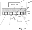
- the light-output device may comprise a plurality of sets of light-sources, for example in the range of from 2 to 100, all comprising at least one light-source configured to emitted light in different angular ranges and each controllable through a respective predetermined range of the dimmer setting.
- a predetermined range of the dimmer setting may correspond to controlling a plurality of sets of light-sources to emit light in their corresponding direction simultaneously.
- At least one of the first and second set of light-sources may comprise an optical element configured to redirect light from the first and/or the second set of light-sources to the first and/or the second angular range.
- the illumination pattern output from the first and/or the second set of light-sources may be further configured.
- the first and/or the second set of light-sources may comprise at least one LED.
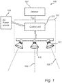
- the invention also relates to a lighting system comprising: the light-output device according to the invention; and a dimmer for enabling user control of the angular light distribution from the light-output device. Effects and features of such lighting system are largely analogous to those described above in connection with the first and second aspects of the invention.
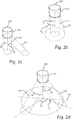
- Fig. 2d further illustrates an embodiment of the light-output device 200 wherein the first and second angular ranges of light are fixed around a given polar angle ⁇ with reference to the optical axis 220, whilst the first angular range 241 of light represents light centered around a first azimuth angle ⁇ 1 , with reference to an azimuth axis 243, and the second angular range 242 of light represents light centered around a second azimuth angle ⁇ 2 with reference to an azimuth axis 243.
- the light-beam emitted by the light-output device can be swept around the optical axis 220 of the light-output device.
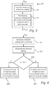
- the generated value X is further evaluated. If the value X is lower than a first predetermined threshold Th1, then a first set of light-sources is controlled to emit light within a first angular range in step 404, and, if the value X is higher than a first predetermined threshold Th1, then a second set of light-sources is controlled to emit light within a second angular range in step 405.
- step 403 wherein the value X is further evaluated against predetermined threshold ranges each corresponding to control of a given set of light-sources.
Landscapes
- Circuit Arrangement For Electric Light Sources In General (AREA)
Claims (12)
- Procédé de commande d'une distribution angulaire d'un faisceau de lumière émis par un dispositif de sortie de lumière (102, 200) comprenant une première source de lumière (105, 211) configurée pour émettre de la lumière à l'intérieur d'une première plage angulaire (221, 231, 241), et une seconde source de lumière (107, 210) configurée pour émettre de la lumière à l'intérieur d'une seconde plage angulaire (222, 232, 242), dans lequel ladite première plage angulaire est différente de ladite seconde plage angulaire, comprenant les étapes de :
réception (401) d'un réglage de gradateur (VDS) d'un gradateur (101) dans lequel ledit réglage de gradateur (VDS) correspond à un certain cycle de service en pourcentage de la forme d'onde sinusoïdale totale de l'alimentation secteur ; caractérisé par les étapes de :- réception séparée du réglage de gradateur, réception d'alimentation d'une forme d'onde de CA externe,- commande (404), si ledit réglage du gradateur est en dessous d'un premier seuil prédéterminé, de ladite première source de lumière pour émettre de la lumière dans ladite première plage angulaire ;- commande (405), si ledit réglage du gradateur est au-dessus dudit premier seuil prédéterminé, de ladite seconde source de lumière pour émettre de la lumière à l'intérieur de ladite seconde plage angulaire ;- mise sous tension de la première source de lumière (105, 211) et de la seconde source de lumière (107, 210) à partir de l'alimentation secteur CA externe. - Procédé selon la revendication 1, dans lequel l'intensité de la lumière émise à partir de ladite première source de lumière est variable en dessous du premier seuil prédéterminé et dans lequel l'intensité de la lumière émise par ladite seconde source de lumière est variable au-dessus du premier seuil prédéterminé, pour permettre une transition continue de l'émission de lumière dans ladite première plage angulaire vers l'émission de lumière dans ladite seconde plage angulaire.
- Procédé selon les revendications 1 ou 2, dans lequel ladite première et ladite seconde plage angulaire correspondent respectivement à une première plage d'angles polaires (θ1) et une seconde plage d'angles polaires (θ2), en référence à un axe optique (220) du dispositif de sortie de lumière.
- Procédé selon l'une quelconque des revendications précédentes, dans lequel ladite première et ladite seconde plage angulaire correspondent respectivement à une première plage d'angles d'azimut (ϕ1) et à une seconde plage d'angles d'azimut (ϕ2), en référence à un axe d'azimut (243) du dispositif de sortie de lumière.
- Unité de commande (103, 201, 300) pour commander une distribution angulaire d'un faisceau de lumière émis par un dispositif de sortie de lumière, le dispositif de sortie de lumière comprenant une première source de lumière (105, 211) configurée pour émettre de la lumière dans une première plage angulaire (221, 231, 341) et une seconde source de lumière (107, 210) configurée pour émettre de la lumière dans une seconde plage angulaire (222, 232, 242), ladite unité de commande comprenant :- une entrée (301) pour recevoir un réglage de gradateur (VDS) d'un gradateur (101) dans lequel ledit réglage de gradateur (VDS) correspond à un certain cycle de service en pourcentage de la forme d'onde sinusoïdale totale de l'alimentation secteur et pour recevoir séparément l'alimentation d'une forme d'onde de CA externe ; et- des circuits de traitement (302) configurés pour :si ledit réglage de gradateur est en dessous d'un premier seuil prédéterminé, commander (404) ladite première source de lumière pour qu'elle émette de la lumière dans ladite première plage angulaire ;si ledit réglage de gradateur est au-dessus dudit premier seuil prédéterminé, commander (405) ladite seconde source de lumière pour qu'elle émette de la lumière dans ladite seconde plage angulaire ;caractérisé en ce que les circuits de traitement sont en outre configurés pour :
mettre sous tension la première source de lumière (105, 211) et la seconde source de lumière (107, 210) à partir de l'alimentation secteur CA externe. - Dispositif de sortie de lumière (102, 200) comprenant :- une première source de lumière (105, 211) configurée pour émettre de la lumière dans une première plage angulaire (221, 231, 241), et- une seconde source de lumière (107, 210) configurée pour émettre de la lumière dans une seconde plage angulaire (222, 232, 242), et- l'unité de commande (103, 201, 300) selon la revendication 5 pour commander une distribution angulaire d'un faisceau de lumière émis par ledit dispositif de sortie de lumière.
- Dispositif de sortie de lumière (102, 200) selon la revendication 6, dans lequel ladite première et ladite seconde plage angulaire correspondent respectivement à une première plage d'angles polaires (θ1) et une seconde plage d'angles polaires (θ2), en référence à un axe optique (220) du dispositif de sortie de lumière.
- Dispositif de sortie de lumière (102, 200) selon la revendication 6 ou 7, dans lequel au moins l'une de ladite première source de lumière et de ladite seconde source de lumière comprend un élément optique (204, 208) configuré pour rediriger la lumière de ladite première source de lumière et/ou de ladite seconde source de lumière vers ladite première et/ou ladite seconde plage angulaire.
- Dispositif de sortie de lumière (102, 200) selon l'une quelconque des revendications 6 à 8, dans lequel ladite première source de lumière et/ou ladite seconde source de lumière comprend au moins une DEL (202, 206).
- Dispositif de sortie de lumière (102, 200) selon l'une quelconque des revendications 6 à 9, dans lequel ladite unité de commande (103, 201, 300) comprend en outre une entrée d'alimentation secteur, ainsi électriquement connectable à une alimentation de secteur de CA (109) pour mettre sous tension ladite première source de lumière ou ladite seconde source de lumière.
- Dispositif de sortie de lumière (102, 200) selon la revendication 10, dans lequel ledit réglage de gradateur est utilisé pour réguler l'alimentation électrique de ladite alimentation secteur de CA (109) à ladite première source de lumière et à ladite seconde source de lumière.
- Système d'éclairage (100) comprenant :un dispositif de sortie de lumière (102, 200) selon l'une quelconque des revendications 6 à 11 ; etun gradateur (101) pour permettre la commande par l'utilisateur de ladite distribution de lumière angulaire à partir dudit dispositif de sortie de lumière.
Priority Applications (2)
| Application Number | Priority Date | Filing Date | Title |
|---|---|---|---|
| EP12712763.7A EP2692211B1 (fr) | 2011-03-30 | 2012-03-23 | Commande par gradateur de la distribution angulaire de la lumière |
| PL12712763T PL2692211T3 (pl) | 2011-03-30 | 2012-03-23 | Sterowanie rozkładem kątowym światła za pomocą ściemniacza |
Applications Claiming Priority (3)
| Application Number | Priority Date | Filing Date | Title |
|---|---|---|---|
| EP11160362 | 2011-03-30 | ||
| PCT/IB2012/051391 WO2012131549A1 (fr) | 2011-03-30 | 2012-03-23 | Commande par gradateur de la distribution angulaire de la lumière |
| EP12712763.7A EP2692211B1 (fr) | 2011-03-30 | 2012-03-23 | Commande par gradateur de la distribution angulaire de la lumière |
Publications (2)
| Publication Number | Publication Date |
|---|---|
| EP2692211A1 EP2692211A1 (fr) | 2014-02-05 |
| EP2692211B1 true EP2692211B1 (fr) | 2019-08-14 |
Family
ID=45932469
Family Applications (1)
| Application Number | Title | Priority Date | Filing Date |
|---|---|---|---|
| EP12712763.7A Active EP2692211B1 (fr) | 2011-03-30 | 2012-03-23 | Commande par gradateur de la distribution angulaire de la lumière |
Country Status (10)
| Country | Link |
|---|---|
| US (1) | US9480116B2 (fr) |
| EP (1) | EP2692211B1 (fr) |
| JP (1) | JP6038113B2 (fr) |
| CN (1) | CN103430627B (fr) |
| DK (1) | DK2692211T3 (fr) |
| ES (1) | ES2752873T3 (fr) |
| PL (1) | PL2692211T3 (fr) |
| PT (1) | PT2692211T (fr) |
| RU (1) | RU2603264C2 (fr) |
| WO (1) | WO2012131549A1 (fr) |
Families Citing this family (9)
| Publication number | Priority date | Publication date | Assignee | Title |
|---|---|---|---|---|
| WO2014115009A1 (fr) * | 2013-01-22 | 2014-07-31 | Koninklijke Philips N.V. | Source de lumière et système d'éclairage pour application d'aquaculture |
| US9374854B2 (en) * | 2013-09-20 | 2016-06-21 | Osram Sylvania Inc. | Lighting techniques utilizing solid-state lamps with electronically adjustable light beam distribution |
| RU2674014C1 (ru) * | 2013-11-20 | 2018-12-04 | Филипс Лайтинг Холдинг Б.В. | Способы и аппарат для управления освещением от осветительного блока с многочисленными источниками света |
| US9699865B2 (en) * | 2015-09-03 | 2017-07-04 | Milwaukee Electric Tool Corporation | Spotlight and method of controlling thereof |
| CN105407606B (zh) * | 2015-11-26 | 2018-05-22 | 苏州灿源照明设备有限公司 | 车位灯组件的控制系统及控制方法 |
| CA2951301C (fr) | 2015-12-09 | 2019-03-05 | Abl Ip Holding Llc | Melange de couleurs destine a l'eclairage a semiconducteur au moyen d'entrainements ca directs |
| US9854637B2 (en) | 2016-05-18 | 2017-12-26 | Abl Ip Holding Llc | Method for controlling a tunable white fixture using a single handle |
| US10874006B1 (en) | 2019-03-08 | 2020-12-22 | Abl Ip Holding Llc | Lighting fixture controller for controlling color temperature and intensity |
| US10728979B1 (en) | 2019-09-30 | 2020-07-28 | Abl Ip Holding Llc | Lighting fixture configured to provide multiple lighting effects |
Family Cites Families (17)
| Publication number | Priority date | Publication date | Assignee | Title |
|---|---|---|---|---|
| US20050265024A1 (en) | 2001-03-22 | 2005-12-01 | Luk John F | Variable beam LED light source system |
| WO2003025458A1 (fr) | 2001-09-17 | 2003-03-27 | Gelcore Llc | Module de projecteur a dispositifs optiques variables |
| JP4366923B2 (ja) * | 2002-04-10 | 2009-11-18 | 日亜化学工業株式会社 | 照明装置およびその制御方法 |
| US7658510B2 (en) | 2004-08-18 | 2010-02-09 | Remco Solid State Lighting Inc. | System and method for power control in a LED luminaire |
| DE102005041234A1 (de) | 2005-08-31 | 2007-03-01 | Hella Kgaa Hueck & Co. | Scheinwerfer für Fahrzeuge |
| KR20070097603A (ko) | 2006-03-28 | 2007-10-05 | 주식회사 필룩스 | Led를 이용한 조명장치 |
| US7288902B1 (en) * | 2007-03-12 | 2007-10-30 | Cirrus Logic, Inc. | Color variations in a dimmable lighting device with stable color temperature light sources |
| US7667408B2 (en) | 2007-03-12 | 2010-02-23 | Cirrus Logic, Inc. | Lighting system with lighting dimmer output mapping |
| WO2008129485A1 (fr) * | 2007-04-24 | 2008-10-30 | Koninklijke Philips Electronics N. V. | Interface utilisateur à multiples paramètres de commande lumineuse |
| CN101878591B (zh) * | 2007-11-08 | 2012-06-20 | 建兴电子科技股份有限公司 | 照明系统 |
| CN101878392B (zh) * | 2007-11-08 | 2011-11-23 | 建兴电子科技股份有限公司 | 照明系统 |
| CN101904222B (zh) | 2007-12-20 | 2014-06-04 | 皇家飞利浦电子股份有限公司 | 两个灯组的场景设置控制 |
| JP2009224220A (ja) * | 2008-03-17 | 2009-10-01 | Panasonic Electric Works Co Ltd | ライトコントローラ |
| US8080942B2 (en) * | 2009-02-24 | 2011-12-20 | Volkswagen Ag | System and method for electronic adaptive front-lighting |
| JP2010287372A (ja) | 2009-06-10 | 2010-12-24 | Mitsubishi Electric Corp | 点灯装置、照明器具および照明制御システム |
| ES2449624T3 (es) * | 2009-07-24 | 2014-03-20 | Koninklijke Philips N.V. | Sistema de iluminación controlable |
| US8820963B2 (en) * | 2011-06-14 | 2014-09-02 | Osram Sylvania Inc. | Solid state light fixture with a tunable angular distribution |
-
2012
- 2012-03-23 JP JP2014501754A patent/JP6038113B2/ja active Active
- 2012-03-23 RU RU2013148100/07A patent/RU2603264C2/ru active
- 2012-03-23 EP EP12712763.7A patent/EP2692211B1/fr active Active
- 2012-03-23 ES ES12712763T patent/ES2752873T3/es active Active
- 2012-03-23 US US14/007,718 patent/US9480116B2/en active Active
- 2012-03-23 CN CN201280016613.3A patent/CN103430627B/zh active Active
- 2012-03-23 PT PT127127637T patent/PT2692211T/pt unknown
- 2012-03-23 WO PCT/IB2012/051391 patent/WO2012131549A1/fr active Application Filing
- 2012-03-23 DK DK12712763T patent/DK2692211T3/da active
- 2012-03-23 PL PL12712763T patent/PL2692211T3/pl unknown
Non-Patent Citations (1)
| Title |
|---|
| None * |
Also Published As
| Publication number | Publication date |
|---|---|
| JP6038113B2 (ja) | 2016-12-07 |
| PL2692211T3 (pl) | 2020-02-28 |
| WO2012131549A1 (fr) | 2012-10-04 |
| CN103430627B (zh) | 2015-11-25 |
| RU2013148100A (ru) | 2015-05-10 |
| US20140015436A1 (en) | 2014-01-16 |
| PT2692211T (pt) | 2019-11-22 |
| ES2752873T3 (es) | 2020-04-06 |
| JP2014512649A (ja) | 2014-05-22 |
| RU2603264C2 (ru) | 2016-11-27 |
| DK2692211T3 (da) | 2019-11-04 |
| US9480116B2 (en) | 2016-10-25 |
| EP2692211A1 (fr) | 2014-02-05 |
| CN103430627A (zh) | 2013-12-04 |
Similar Documents
| Publication | Publication Date | Title |
|---|---|---|
| EP2692211B1 (fr) | Commande par gradateur de la distribution angulaire de la lumière | |
| US10966295B2 (en) | System and method for controlling operation of an LED-based light | |
| US10598363B2 (en) | Apparatus and method for providing downlighting and wall-washing lighting effects | |
| JP5509489B2 (ja) | 電力波形を切除し輝度調節する照明・調光装置 | |
| EP3072156B1 (fr) | Procédés et appareil de commande de l'éclairage émis par une unité d'éclairage à plusieurs sources de lumière | |
| US10375807B1 (en) | Controller with peripheral visual feedback | |
| JP2013503428A (ja) | 照明器具及び照明器具を制御するための方法 | |
| US10085318B2 (en) | Lighting unit with multiple light sources to emit functional light or dynamic lighting effect | |
| JP2012243458A (ja) | 照明装置及び照明器具 | |
| EP3555524B1 (fr) | Appareil d'éclairage à base de del | |
| KR20140122045A (ko) | 스위칭 패턴을 이용해 조광 제어 가능한 led 조명 장치 | |
| JP6292510B2 (ja) | 調光装置及びそれを用いた照明システム | |
| US8646941B1 (en) | Lighting apparatus and method | |
| EP3214902A1 (fr) | Système d'éclairage à courant continu basse tension à adresses d'identification | |
| CN113056064A (zh) | 一种智能灯具的调节方法及调节系统 | |
| JP2012204175A (ja) | 照明装置及びこの照明装置を用いた照明制御システム | |
| JP5907344B2 (ja) | 照明制御システムおよび照明制御方法 | |
| CN213755046U (zh) | 一种可降低室内电磁辐射的照明系统 | |
| KR100839435B1 (ko) | Rgb led를 이용한 컬러 테라피 벽면조명 시스템 | |
| KR20110104136A (ko) | 체인형 엘이디 조명용 에스엠피에스 및 조명제어장치 | |
| CN107676699A (zh) | 一种基于红外感应的吸顶灯泡及吸顶灯具 | |
| KR20150051638A (ko) | 시간 분배 신호를 이용한 색 가변 조명 장치 | |
| TWM526648U (zh) | 可調光之智慧型繼電器 |
Legal Events
| Date | Code | Title | Description |
|---|---|---|---|
| PUAI | Public reference made under article 153(3) epc to a published international application that has entered the european phase |
Free format text: ORIGINAL CODE: 0009012 |
|
| 17P | Request for examination filed |
Effective date: 20131030 |
|
| AK | Designated contracting states |
Kind code of ref document: A1 Designated state(s): AL AT BE BG CH CY CZ DE DK EE ES FI FR GB GR HR HU IE IS IT LI LT LU LV MC MK MT NL NO PL PT RO RS SE SI SK SM TR |
|
| DAX | Request for extension of the european patent (deleted) | ||
| 17Q | First examination report despatched |
Effective date: 20160512 |
|
| RAP1 | Party data changed (applicant data changed or rights of an application transferred) |
Owner name: PHILIPS LIGHTING HOLDING B.V. |
|
| STAA | Information on the status of an ep patent application or granted ep patent |
Free format text: STATUS: EXAMINATION IS IN PROGRESS |
|
| RIN1 | Information on inventor provided before grant (corrected) |
Inventor name: BERGMAN, ANTHONIE, HENDRIK Inventor name: VAN GORKOM, RAMON, PASCAL Inventor name: TUKKER, TEUNIS, WILLEM Inventor name: KRIJN, MARCELLINUS, PETRUS, CAROLUS, MICHAEL Inventor name: VISSENBERG, MICHEL, CORNELIS, JOSEPHUS, MARIE Inventor name: ANSEMS, JOHANNES, PETRUS, MARIA |
|
| RAP1 | Party data changed (applicant data changed or rights of an application transferred) |
Owner name: PHILIPS LIGHTING HOLDING B.V. |
|
| GRAP | Despatch of communication of intention to grant a patent |
Free format text: ORIGINAL CODE: EPIDOSNIGR1 |
|
| STAA | Information on the status of an ep patent application or granted ep patent |
Free format text: STATUS: GRANT OF PATENT IS INTENDED |
|
| RAP1 | Party data changed (applicant data changed or rights of an application transferred) |
Owner name: SIGNIFY HOLDING B.V. |
|
| INTG | Intention to grant announced |
Effective date: 20190313 |
|
| GRAS | Grant fee paid |
Free format text: ORIGINAL CODE: EPIDOSNIGR3 |
|
| GRAA | (expected) grant |
Free format text: ORIGINAL CODE: 0009210 |
|
| STAA | Information on the status of an ep patent application or granted ep patent |
Free format text: STATUS: THE PATENT HAS BEEN GRANTED |
|
| AK | Designated contracting states |
Kind code of ref document: B1 Designated state(s): AL AT BE BG CH CY CZ DE DK EE ES FI FR GB GR HR HU IE IS IT LI LT LU LV MC MK MT NL NO PL PT RO RS SE SI SK SM TR |
|
| REG | Reference to a national code |
Ref country code: GB Ref legal event code: FG4D |
|
| REG | Reference to a national code |
Ref country code: CH Ref legal event code: EP Ref country code: AT Ref legal event code: REF Ref document number: 1168587 Country of ref document: AT Kind code of ref document: T Effective date: 20190815 |
|
| REG | Reference to a national code |
Ref country code: DE Ref legal event code: R096 Ref document number: 602012062918 Country of ref document: DE |
|
| REG | Reference to a national code |
Ref country code: IE Ref legal event code: FG4D |
|
| REG | Reference to a national code |
Ref country code: NO Ref legal event code: T2 Effective date: 20190814 Ref country code: DK Ref legal event code: T3 Effective date: 20191031 |
|
| REG | Reference to a national code |
Ref country code: NL Ref legal event code: FP |
|
| REG | Reference to a national code |
Ref country code: PT Ref legal event code: SC4A Ref document number: 2692211 Country of ref document: PT Date of ref document: 20191122 Kind code of ref document: T Free format text: AVAILABILITY OF NATIONAL TRANSLATION Effective date: 20191113 |
|
| REG | Reference to a national code |
Ref country code: SE Ref legal event code: TRGR |
|
| REG | Reference to a national code |
Ref country code: LT Ref legal event code: MG4D |
|
| PG25 | Lapsed in a contracting state [announced via postgrant information from national office to epo] |
Ref country code: HR Free format text: LAPSE BECAUSE OF FAILURE TO SUBMIT A TRANSLATION OF THE DESCRIPTION OR TO PAY THE FEE WITHIN THE PRESCRIBED TIME-LIMIT Effective date: 20190814 Ref country code: LT Free format text: LAPSE BECAUSE OF FAILURE TO SUBMIT A TRANSLATION OF THE DESCRIPTION OR TO PAY THE FEE WITHIN THE PRESCRIBED TIME-LIMIT Effective date: 20190814 Ref country code: BG Free format text: LAPSE BECAUSE OF FAILURE TO SUBMIT A TRANSLATION OF THE DESCRIPTION OR TO PAY THE FEE WITHIN THE PRESCRIBED TIME-LIMIT Effective date: 20191114 |
|
| PG25 | Lapsed in a contracting state [announced via postgrant information from national office to epo] |
Ref country code: AL Free format text: LAPSE BECAUSE OF FAILURE TO SUBMIT A TRANSLATION OF THE DESCRIPTION OR TO PAY THE FEE WITHIN THE PRESCRIBED TIME-LIMIT Effective date: 20190814 Ref country code: GR Free format text: LAPSE BECAUSE OF FAILURE TO SUBMIT A TRANSLATION OF THE DESCRIPTION OR TO PAY THE FEE WITHIN THE PRESCRIBED TIME-LIMIT Effective date: 20191115 Ref country code: LV Free format text: LAPSE BECAUSE OF FAILURE TO SUBMIT A TRANSLATION OF THE DESCRIPTION OR TO PAY THE FEE WITHIN THE PRESCRIBED TIME-LIMIT Effective date: 20190814 Ref country code: RS Free format text: LAPSE BECAUSE OF FAILURE TO SUBMIT A TRANSLATION OF THE DESCRIPTION OR TO PAY THE FEE WITHIN THE PRESCRIBED TIME-LIMIT Effective date: 20190814 Ref country code: IS Free format text: LAPSE BECAUSE OF FAILURE TO SUBMIT A TRANSLATION OF THE DESCRIPTION OR TO PAY THE FEE WITHIN THE PRESCRIBED TIME-LIMIT Effective date: 20191214 |
|
| REG | Reference to a national code |
Ref country code: CH Ref legal event code: NV Representative=s name: VALIPAT S.A. C/O BOVARD SA NEUCHATEL, CH |
|
| REG | Reference to a national code |
Ref country code: ES Ref legal event code: FG2A Ref document number: 2752873 Country of ref document: ES Kind code of ref document: T3 Effective date: 20200406 |
|
| PG25 | Lapsed in a contracting state [announced via postgrant information from national office to epo] |
Ref country code: RO Free format text: LAPSE BECAUSE OF FAILURE TO SUBMIT A TRANSLATION OF THE DESCRIPTION OR TO PAY THE FEE WITHIN THE PRESCRIBED TIME-LIMIT Effective date: 20190814 Ref country code: EE Free format text: LAPSE BECAUSE OF FAILURE TO SUBMIT A TRANSLATION OF THE DESCRIPTION OR TO PAY THE FEE WITHIN THE PRESCRIBED TIME-LIMIT Effective date: 20190814 |
|
| PG25 | Lapsed in a contracting state [announced via postgrant information from national office to epo] |
Ref country code: CZ Free format text: LAPSE BECAUSE OF FAILURE TO SUBMIT A TRANSLATION OF THE DESCRIPTION OR TO PAY THE FEE WITHIN THE PRESCRIBED TIME-LIMIT Effective date: 20190814 Ref country code: IS Free format text: LAPSE BECAUSE OF FAILURE TO SUBMIT A TRANSLATION OF THE DESCRIPTION OR TO PAY THE FEE WITHIN THE PRESCRIBED TIME-LIMIT Effective date: 20200224 Ref country code: SM Free format text: LAPSE BECAUSE OF FAILURE TO SUBMIT A TRANSLATION OF THE DESCRIPTION OR TO PAY THE FEE WITHIN THE PRESCRIBED TIME-LIMIT Effective date: 20190814 Ref country code: SK Free format text: LAPSE BECAUSE OF FAILURE TO SUBMIT A TRANSLATION OF THE DESCRIPTION OR TO PAY THE FEE WITHIN THE PRESCRIBED TIME-LIMIT Effective date: 20190814 |
|
| REG | Reference to a national code |
Ref country code: DE Ref legal event code: R097 Ref document number: 602012062918 Country of ref document: DE |
|
| PLBE | No opposition filed within time limit |
Free format text: ORIGINAL CODE: 0009261 |
|
| STAA | Information on the status of an ep patent application or granted ep patent |
Free format text: STATUS: NO OPPOSITION FILED WITHIN TIME LIMIT |
|
| PG2D | Information on lapse in contracting state deleted |
Ref country code: IS |
|
| 26N | No opposition filed |
Effective date: 20200603 |
|
| PG25 | Lapsed in a contracting state [announced via postgrant information from national office to epo] |
Ref country code: SI Free format text: LAPSE BECAUSE OF FAILURE TO SUBMIT A TRANSLATION OF THE DESCRIPTION OR TO PAY THE FEE WITHIN THE PRESCRIBED TIME-LIMIT Effective date: 20190814 |
|
| PG25 | Lapsed in a contracting state [announced via postgrant information from national office to epo] |
Ref country code: MC Free format text: LAPSE BECAUSE OF FAILURE TO SUBMIT A TRANSLATION OF THE DESCRIPTION OR TO PAY THE FEE WITHIN THE PRESCRIBED TIME-LIMIT Effective date: 20190814 |
|
| PG25 | Lapsed in a contracting state [announced via postgrant information from national office to epo] |
Ref country code: LU Free format text: LAPSE BECAUSE OF NON-PAYMENT OF DUE FEES Effective date: 20200323 |
|
| PG25 | Lapsed in a contracting state [announced via postgrant information from national office to epo] |
Ref country code: IE Free format text: LAPSE BECAUSE OF NON-PAYMENT OF DUE FEES Effective date: 20200323 |
|
| REG | Reference to a national code |
Ref country code: AT Ref legal event code: UEP Ref document number: 1168587 Country of ref document: AT Kind code of ref document: T Effective date: 20190814 |
|
| PG25 | Lapsed in a contracting state [announced via postgrant information from national office to epo] |
Ref country code: MT Free format text: LAPSE BECAUSE OF FAILURE TO SUBMIT A TRANSLATION OF THE DESCRIPTION OR TO PAY THE FEE WITHIN THE PRESCRIBED TIME-LIMIT Effective date: 20190814 Ref country code: CY Free format text: LAPSE BECAUSE OF FAILURE TO SUBMIT A TRANSLATION OF THE DESCRIPTION OR TO PAY THE FEE WITHIN THE PRESCRIBED TIME-LIMIT Effective date: 20190814 |
|
| PG25 | Lapsed in a contracting state [announced via postgrant information from national office to epo] |
Ref country code: MK Free format text: LAPSE BECAUSE OF FAILURE TO SUBMIT A TRANSLATION OF THE DESCRIPTION OR TO PAY THE FEE WITHIN THE PRESCRIBED TIME-LIMIT Effective date: 20190814 |
|
| PGFP | Annual fee paid to national office [announced via postgrant information from national office to epo] |
Ref country code: NO Payment date: 20230328 Year of fee payment: 12 Ref country code: FR Payment date: 20230323 Year of fee payment: 12 Ref country code: DK Payment date: 20230323 Year of fee payment: 12 |
|
| PGFP | Annual fee paid to national office [announced via postgrant information from national office to epo] |
Ref country code: TR Payment date: 20230310 Year of fee payment: 12 Ref country code: SE Payment date: 20230317 Year of fee payment: 12 Ref country code: PL Payment date: 20230310 Year of fee payment: 12 Ref country code: IT Payment date: 20230321 Year of fee payment: 12 Ref country code: BE Payment date: 20230323 Year of fee payment: 12 |
|
| P01 | Opt-out of the competence of the unified patent court (upc) registered |
Effective date: 20230421 |
|
| PGFP | Annual fee paid to national office [announced via postgrant information from national office to epo] |
Ref country code: ES Payment date: 20230424 Year of fee payment: 12 Ref country code: DE Payment date: 20230530 Year of fee payment: 12 Ref country code: CH Payment date: 20230402 Year of fee payment: 12 |
|
| PGFP | Annual fee paid to national office [announced via postgrant information from national office to epo] |
Ref country code: NL Payment date: 20240326 Year of fee payment: 13 |
|
| PGFP | Annual fee paid to national office [announced via postgrant information from national office to epo] |
Ref country code: AT Payment date: 20240319 Year of fee payment: 13 |
|
| PGFP | Annual fee paid to national office [announced via postgrant information from national office to epo] |
Ref country code: FI Payment date: 20240326 Year of fee payment: 13 Ref country code: PT Payment date: 20240311 Year of fee payment: 13 Ref country code: GB Payment date: 20240319 Year of fee payment: 13 |