EP2690884A2 - Audiovorrichtung mit Stummschaltungsfunktion - Google Patents
Audiovorrichtung mit Stummschaltungsfunktion Download PDFInfo
- Publication number
- EP2690884A2 EP2690884A2 EP20130164166 EP13164166A EP2690884A2 EP 2690884 A2 EP2690884 A2 EP 2690884A2 EP 20130164166 EP20130164166 EP 20130164166 EP 13164166 A EP13164166 A EP 13164166A EP 2690884 A2 EP2690884 A2 EP 2690884A2
- Authority
- EP
- European Patent Office
- Prior art keywords
- mute
- detection unit
- signal
- output
- volume
- Prior art date
- Legal status (The legal status is an assumption and is not a legal conclusion. Google has not performed a legal analysis and makes no representation as to the accuracy of the status listed.)
- Granted
Links
Images


Classifications
-
- H—ELECTRICITY
- H03—ELECTRONIC CIRCUITRY
- H03G—CONTROL OF AMPLIFICATION
- H03G3/00—Gain control in amplifiers or frequency changers
- H03G3/20—Automatic control
-
- H—ELECTRICITY
- H04—ELECTRIC COMMUNICATION TECHNIQUE
- H04R—LOUDSPEAKERS, MICROPHONES, GRAMOPHONE PICK-UPS OR LIKE ACOUSTIC ELECTROMECHANICAL TRANSDUCERS; DEAF-AID SETS; PUBLIC ADDRESS SYSTEMS
- H04R29/00—Monitoring arrangements; Testing arrangements
- H04R29/001—Monitoring arrangements; Testing arrangements for loudspeakers
-
- H—ELECTRICITY
- H04—ELECTRIC COMMUNICATION TECHNIQUE
- H04R—LOUDSPEAKERS, MICROPHONES, GRAMOPHONE PICK-UPS OR LIKE ACOUSTIC ELECTROMECHANICAL TRANSDUCERS; DEAF-AID SETS; PUBLIC ADDRESS SYSTEMS
- H04R3/00—Circuits for transducers, loudspeakers or microphones
- H04R3/007—Protection circuits for transducers
-
- H—ELECTRICITY
- H04—ELECTRIC COMMUNICATION TECHNIQUE
- H04R—LOUDSPEAKERS, MICROPHONES, GRAMOPHONE PICK-UPS OR LIKE ACOUSTIC ELECTROMECHANICAL TRANSDUCERS; DEAF-AID SETS; PUBLIC ADDRESS SYSTEMS
- H04R1/00—Details of transducers, loudspeakers or microphones
- H04R1/10—Earpieces; Attachments therefor ; Earphones; Monophonic headphones
- H04R1/1041—Mechanical or electronic switches, or control elements
-
- H—ELECTRICITY
- H04—ELECTRIC COMMUNICATION TECHNIQUE
- H04R—LOUDSPEAKERS, MICROPHONES, GRAMOPHONE PICK-UPS OR LIKE ACOUSTIC ELECTROMECHANICAL TRANSDUCERS; DEAF-AID SETS; PUBLIC ADDRESS SYSTEMS
- H04R2420/00—Details of connection covered by H04R, not provided for in its groups
- H04R2420/03—Connection circuits to selectively connect loudspeakers or headphones to amplifiers
-
- H—ELECTRICITY
- H04—ELECTRIC COMMUNICATION TECHNIQUE
- H04R—LOUDSPEAKERS, MICROPHONES, GRAMOPHONE PICK-UPS OR LIKE ACOUSTIC ELECTROMECHANICAL TRANSDUCERS; DEAF-AID SETS; PUBLIC ADDRESS SYSTEMS
- H04R2420/00—Details of connection covered by H04R, not provided for in its groups
- H04R2420/09—Applications of special connectors, e.g. USB, XLR, in loudspeakers, microphones or headphones
-
- H—ELECTRICITY
- H04—ELECTRIC COMMUNICATION TECHNIQUE
- H04R—LOUDSPEAKERS, MICROPHONES, GRAMOPHONE PICK-UPS OR LIKE ACOUSTIC ELECTROMECHANICAL TRANSDUCERS; DEAF-AID SETS; PUBLIC ADDRESS SYSTEMS
- H04R2430/00—Signal processing covered by H04R, not provided for in its groups
- H04R2430/01—Aspects of volume control, not necessarily automatic, in sound systems
Definitions
- the present invention relates to an audio device and in particular, to a mute function.
- audio devices provided with a headphone output are designed to activate a mute function at the time of power ON/OFF so as not to output a click noise. Further, another function is also suggested to limit an output level so as not to provide an excessive volume output when a headphone plug is inserted into a jack.
- JP 11-136789 A describes that an audio output is automatically set to mute or low level in response to pulling out of a headphone plug.
- the volume is automatically set to zero when a headphone plug is pulled out.
- the volume should be manually adjusted from the volume zero, when a headphone plug is inserted.
- JP 2002-010389 A describes that an audio level is automatically set to mute in response to pulling out of a headphone plug, and then the audio level is automatically returned to a normal level. After the audio level is set to mute, the mute position is maintained until a user adjusts a volume setting.
- JP 11-136789 A nowhere provides a specific description about a mute control at the time of power ON/OFF, an excessive volume output is still possible when the power supply is turned from OFF to ON with a headphone plug inserted, depending on a volume setting level.
- JP 2002-010389 A because a mute mode is maintained until a volume setting is adjusted, there is a problem that an audio output cannot be confirmed until the volume setting is completed. Further, there is another problem that, if a volume setting is erroneously adjusted, an output may be made at an excessive volume when the mute mode is canceled.
- the present invention provides an audio device that can prevent excessive volume output at the time of changing headphones or changing an input source, as well as at the time of turning power from OFF to ON.
- An audio device with a mute function comprises a first detection unit that detects insertion of a headphone plug; a second detection unit that detects a volume position; and a control unit that controls a mute mode when a power supply is ON such that when the first detection unit detects no insertion of the headphone plug, the mute mode is activated so as not to output an audio signal; when the first detection unit detects the insertion of the headphone plug and the second detection unit does not detect that the volume position is set at a mute position or near to the mute position, the mute mode is maintained; and when the first detection unit detects the insertion of the headphone plug and the second detection unit detects that the volume position is set at the mute position or near to the mute position, the mute mode is canceled.
- another audio device with a mute function comprises a first detection unit that detects an input source change; a second detection unit that detects a volume position; and a control unit that controls a mute mode when a power supply is ON such that when the first detection unit detects the input source change, the mute mode is activated so as not to output an audio signal; when the first detection unit detects no input source change and the second detection unit does not detect that the volume position is set at a mute position or near to the mute position, the mute mode is maintained; and when the first detection unit detects no input source change and the second detection unit detects that the volume position is set at the mute position or near to the mute position, the mute mode is canceled.
- yet another audio device with a mute function comprises a first detection unit that detects insertion or pulling out of a headphone plug; a second detection unit that detects a volume position; and a control unit that controls a mute mode when a power supply is ON such that when the first detection unit detects no insertion or pulling out of the headphone plug, the mute mode is activated so as not to output an audio signal; when the first detection unit detects the insertion or pulling out of the headphone plug and the second detection unit does not detect that the volume position is set at a mute position or near to the mute position, the mute mode is maintained; and when the first detection unit detects the insertion or pulling out of the headphone plug and the second detection unit detects that the volume position is set at the mute position or near to the mute position, the mute mode is canceled.
- a setting is once changed to a mute mode at the time of insertion or pulling out of a headphone plug or changing of an input source, such that the mute mode is maintained unless the volume position is set to a mute position or near to the mute position. Because the mute mode is canceled to enable an audio output only when the volume position is set to a mute position or near to the mute position, it is possible to reliably prevent an audio output at an unintentional excessive volume.
- FIG. 1 shows a circuit configuration of an audio device according to an embodiment of the present invention.
- the audio device is provided with a mute control circuit 10 which controls ON and OFF of a mute mode.
- the mute control circuit 10 is provided with a volume position detection switch 12 which detects a volume position of an analog volume 13; a headphone detection switch 14 which detects insertion of a headphone plug into a headphone jack; an OR gate 16; an AND gate 20; and a power supply circuit 18.
- An output of the mute control circuit 10, which means an output of the AND gate 20, is supplied to a mute switch 24 which controls ON and OFF of the mute mode.
- the mute switch 24 switches between whether to connect an output of an amplifier 22 which amplifies audio signals (mute OFF indicating that the mute mode is canceled) or to disconnect the output of the amplifier 22 (mute ON).
- the mute switch 24 is ON, the mute mode is canceled causing audio signals to be output to a headphone 26.
- the mute switch 24 is OFF, the mute mode is activated causing no audio signals to be output to the headphone 26.
- the volume position detection switch 12 detects a position of the analog volume 13. More specifically, the volume position detection switch 12 detects that the position of the analog volume 13 is at the "- ⁇ " position (mute mode). When the position of the analog volume 13 is at the "- ⁇ " position, the volume position detection switch 12 is turned OFF causing a HIGH signal to be output after being inverted by an inverter. When the position of the analog volume 13 is at a position other than the "- ⁇ " position, the volume position detection switch 12 is turned ON such that a low signal is output after being inverted by the inverter. A detection signal from the volume position detection switch 12 is supplied to the OR gate 16.
- the headphone detection switch 14 detects insertion of a headphone plug into a jack. When a headphone plug is inserted, the headphone detection switch 14 outputs a HIGH signal. Otherwise, the headphone detection switch 14 outputs a LOW signal. Adetection signal from the headphone detection switch 14 is supplied to the AND gate 20.
- the detection signal from the volume position detection switch 12 is supplied, while to the other terminal, an output signal from the AND gate 20 is supplied.
- the OR gate 16 calculates a logical sum of these two input signals and outputs the obtained logical sum to the AND gate 20.
- the power supply circuit 18 is provided with an AC plug, a rectifier circuit, a power supply voltage detection circuit, a delay circuit, a power supply disconnection detection circuit, and an inverter.
- the power supply voltage detection circuit and the delay circuit function in such a manner that in response to a detection of turning ON of the power supply, a HIGH signal is output after waiting for a certain period of time predetermined as a delay time until the circuit reaches a steady state. Further, the power supply disconnection detection circuit and the inverter function in such a manner that in response to a detection of OFF of the power supply, a LOW signal is output. In other words, a HIGH signal is output when it is detected that the power supply is not OFF. Two signals from the power supply circuit 18 (a detection signal indicating that the power supply is turned ON and a detection signal indicating that the power supply is not turned OFF) are supplied to the AND gate 20.
- the AND gate 20 calculates a logical product of four outputs, which are an output from the OR gate 16, an output from the headphone detection switch 14, and two outputs from the power supply circuit 18, and controls ON and OFF of the mute mode by supplying the obtained logical product to the mute switch 24.
- the output of the AND gate 20 becomes HIGH when all of the outputs from the OR gate 16, the headphone detection switch 14, and the power supply circuit 18 are HIGH and thereby the mute switch 24 is turned ON to cancel the mute mode.
- the output of the AND gate 20 becomes LOW when any one of the outputs from the OR gate 16, the headphone detection switch 14, and the power supply circuit 18 is LOW and thereby the mute switch 24 is turned OFF to activate the mute mode.
- the output from the AND gate 20 is also supplied to the other terminal of the OR gate 16. Therefore, when the output from the AND gate 20 becomes HIGH, a HIGH signal is output from the OR gate 16 even when the detection signal from the volume position detection switch 12 is LOW. This state is maintained until the output from the AND gate 20 becomes LOW.
- the headphone detection switch 14 When the power supply is turned ON and a headphone plug is inserted into a jack, the headphone detection switch 14 outputs a HIGH signal (the output signal is changed from LOW to HIGH). Therefore, ON or OFF of the mute mode is determined in accordance with a signal from the volume position detection switch 12.
- the analog volume 13 when the analog volume 13 is at a position other than the "- ⁇ " position, for example, when the analog volume 13 is at a certain level (any level other than the "- ⁇ ” position), a low signal is output from the volume position detection switch 12 and thereby the output from the AND gate 20 is LOW. Therefore, even when a headphone plug is inserted into a jack, the mute switch 24 is OFF to maintain the mute mode.
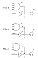
- FIGs. 2 and 3 shows an input/output state of the AND gate 20 and a state of the mute switch 24 when the power supply is ON and a headphone plug is inserted into a jack.
- FIG. 2 shows a state when the analog volume 13 is set at a position other than the "- ⁇ " position. Because, among the inputs supplied to the AND gate 20, the signal from the volume position detection switch 12 is a LOW signal (indicated by "L” in the drawing), the output from the AND gate 20 becomes LOW causing the mute switch 24 to be turned OFF to activate the mute mode. Therefore, even when the analog volume 13 is set to a certain level, no audio signals are output.
- FIG. 3 shows a state when a user has turned the analog volume 13 to the "- ⁇ " position. Because, among the inputs supplied to the AND gate 20, the signal from the volume position detection switch 12 becomes also a HIGH signal (indicatedby "H” in the drawing), the output from the AND gate 20 becomes HIGH causing the mute switch 24 to be turned ON to cancel the mute mode. Therefore, if a user turns the analog volume 13 to a certain level from such a condition, an audio signal amplified to that level is output.
- a LOW signal is output from the headphone detection switch 14 and thereby the output from the AND gate 20 becomes LOW causing the mute switch 24 to turned OFF to activate the mute mode.
- FIG. 4 shows an input/output state of the AND gate 20 and a state of the mute switch 24 in this case. Because, among the inputs supplied to the AND gate 20, the signal from the headphone detection switch 14 is a low signal (indicated by "L" in the drawing), the output from the AND gate 20 becomes LOW causing the mute switch 24 to be turned OFF to activate the mute mode. Therefore, no audio signals are output even when the analog volume 13 is set at a certain level.
- the ON and OFF of the mute mode is determined in accordance with the signal from the volume position detection switch 12 as in the above CASE (2).
- the mute mode is maintained until a certain period of time (delay time applied by the delay circuit) has passed.
- delay time applied by the delay circuit it becomes possible to cancel the mute mode after this period, because the mute mode continues to be maintained unless the headphone plug 26 is inserted into the jack and the analog volume 13 is set at the "- ⁇ " position, an output at an unexpected excessive volume which would be caused by setting the analog volume 13 at a certain level can be prevented at the time of turning the power supply ON.
- the mute mode is automatically activated when the headphone plug 26 is pulled out and the mute mode is maintained until the analog volume 13 is set at the "- ⁇ " position, it is possible, even when another headphone plug 26 is inserted, to prevent an excessive volume output due to the different impedance.
- the present embodiment is particularly advantageous in an environment where an unspecified large number of users can try listening and viewing using various headphones.
- the mute mode it is also possible to make ON and OFF of the mute mode visually recognizable by supplying the output from the AND gate 20 to an LED. For example, it is possible to notify that the mute mode is activated by turning ON a mute LED when the output of the AND gate 20 is LOW.
- the mute LED is turned ON notifying the user that the mute mode is activated.
- the mute LED is turned OFF to notify the user that audio output is possible.
- the mute mode is canceled when the analog volume 13 is set to the "- ⁇ " position.
- the position is not necessarily at the exact " - ⁇ " position.
- the mute mode may be canceled when the analog volume 13 is set near the "- ⁇ ” position.
- the mute mode may be canceled when it is detected that the analog volume 13 is intentionally turned at least toward the "- ⁇ " position or near the "- ⁇ ” position.
- the mute mode may be canceled by using, as a trigger, an operation to set the analog volume level to low to such an extent that the output would not be at an excessive volume even when the impedances or efficiencies of headphones 26 are different from each other.
- the embodiments can be similarly applied for replacing an input source, for example, from CD to PC.
- an input source change detection switch may be used in place of the headphone detection switch 14.
- FIG. 5 shows a configuration in this case.
- An input source change detection switch 15 operates in response to a change of an input source such that the input source change detection switch 15 outputs a LOW signal to the AND gate 20 at a time when the input source is changed. Otherwise, the input source change detection switch 15 outputs a HIGH signal to the AND gate 20. Because a signal from the input source change detection switch 15 temporarily becomes LOW signals when an input source is changed, the output from the AND gate 20 becomes LOW causing the mute switch 24 to be turned OFF to activate the mute mode.
- the mute mode is maintained because the signal from the volume position detection switch 12 remains LOW unless the analog volume 13 is set at the "- ⁇ " position or near the "- ⁇ ” position. This makes it possible, even if the input source is changed with the analog volume 13 set at a certain level (any level other than the "- ⁇ " position or near the "- ⁇ ” position), to prevent an excessive volume output. Needless to say, the mute mode may be used both for replacing headphones and changing an input source.
- the above embodiments are described by assuming use with a headphone amplifier.
- the present invention may also be applied to an amplifier with a speaker output.
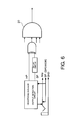
- an amplifier with a speaker output in a circuit shown in FIG. 1 , because when a headphone plug is pulled out from a jack, the headphone detection switch 14 keeps outputting a LOW signal, the mute mode is not canceled even when the analog volume 13 is set at the "- ⁇ " position or near the "- ⁇ ” position and thereby no audio is output from the speaker. Therefore, as shown in FIG.
- a headphone output detection signal is supplied to, for example, one of the input terminals of an EXOR gate (exclusive OR circuit), while a speaker output detection signal is connected to the other input terminal of the EXOR gate via the delay circuit.
- the output signal from the EXOR gate is connected to the input terminal of the AND gate 20. Because, when a headphone plug is inserted into a jack, the headphone output detection signal is HIGH, and the speaker output detection signal is LOW, the output from the EXOR gate becomes HIGH. When a headphone plug is pulled out from a jack under such circumstances, the headphone output detection signal becomes LOW and the speaker output detection signal becomes HIGH.
- both inputs to the EXOR gate become LOW during the delay time applied by the delay circuit. Therefore, the output from the EXOR gate temporality becomes LOW, and thereby the output from the AND gate 20 can be made LOW. Because, after the delay time, the speaker output detection signal which is input to the EXOR gate becomes HIGH and thereby the output from the EXOR gate becomes HIGH, it becomes possible to control ON and OFF of the mute mode by a signal from the volume position detection switch 12. The same operations are applicable when a headphone plug is inserted into a jack.
- the output of the EXOR gate becomes HIGH.
- the headphone output detection signal becomes HIGH and the speaker output detection signal becomes LOW.
- both inputs to the EXOR gate become HIGH during the delay time applied by the delay circuit. Therefore, during the delay time, the output from the EXOR gate temporality becomes low and the output from the AND gate 20 can be made LOW.
- the speaker output detection signal which is input to the EXOR gate becomes LOW and the output from the EXOR gate becomes HIGH. Therefore, it becomes possible to control ON and OFF of the mute mode with the signal from the volume position detection switch 12.
- the delay circuit may be provided not on the supply line side of the speaker output detection signal but on the supply line side of the headphone output detection signal.
- a mute control is realized by the circuit configuration shown in FIG. 1 or FIG. 5 in the above embodiments, it is also possible to realize, by a microcomputer, the detection and the mute control realized by the various switches.
Landscapes
- Physics & Mathematics (AREA)
- Engineering & Computer Science (AREA)
- Acoustics & Sound (AREA)
- Signal Processing (AREA)
- Health & Medical Sciences (AREA)
- General Health & Medical Sciences (AREA)
- Otolaryngology (AREA)
- Circuit For Audible Band Transducer (AREA)
- Soundproofing, Sound Blocking, And Sound Damping (AREA)
- Amplifiers (AREA)
Applications Claiming Priority (1)
| Application Number | Priority Date | Filing Date | Title |
|---|---|---|---|
| JP2012164086A JP6089478B2 (ja) | 2012-07-24 | 2012-07-24 | ミュート機能を備えるオーディオ装置 |
Publications (3)
| Publication Number | Publication Date |
|---|---|
| EP2690884A2 true EP2690884A2 (de) | 2014-01-29 |
| EP2690884A3 EP2690884A3 (de) | 2015-02-11 |
| EP2690884B1 EP2690884B1 (de) | 2017-05-31 |
Family
ID=48143474
Family Applications (1)
| Application Number | Title | Priority Date | Filing Date |
|---|---|---|---|
| EP13164166.4A Not-in-force EP2690884B1 (de) | 2012-07-24 | 2013-04-17 | Audiovorrichtung mit Stummschaltungsfunktion |
Country Status (4)
| Country | Link |
|---|---|
| US (1) | US9112468B2 (de) |
| EP (1) | EP2690884B1 (de) |
| JP (1) | JP6089478B2 (de) |
| CN (1) | CN103581795B (de) |
Families Citing this family (4)
| Publication number | Priority date | Publication date | Assignee | Title |
|---|---|---|---|---|
| CN106325805A (zh) * | 2016-08-17 | 2017-01-11 | 北京小米移动软件有限公司 | 音频播放方法及装置 |
| CN106851488B (zh) * | 2017-03-30 | 2020-06-30 | 重庆辉烨通讯技术有限公司 | 音频输出的控制方法、装置和电路 |
| JP2020136865A (ja) * | 2019-02-18 | 2020-08-31 | キヤノン株式会社 | 電子機器、その制御方法、およびそのプログラム |
| KR102820937B1 (ko) * | 2024-02-21 | 2025-06-13 | 최성찬 | 비대면 양방향 마이크 |
Citations (2)
| Publication number | Priority date | Publication date | Assignee | Title |
|---|---|---|---|---|
| JPH11136789A (ja) | 1997-10-29 | 1999-05-21 | Teac Corp | ヘッドホンジャックを有するオ−ディオ装置 |
| JP2002010389A (ja) | 2000-06-20 | 2002-01-11 | Toshiba Corp | 音声再生装置 |
Family Cites Families (4)
| Publication number | Priority date | Publication date | Assignee | Title |
|---|---|---|---|---|
| JPH03149996A (ja) * | 1989-11-06 | 1991-06-26 | Sanyo Electric Co Ltd | 電動ボリューム装置 |
| KR100544460B1 (ko) | 2003-11-21 | 2006-01-24 | 삼성전자주식회사 | 리모콘장치의 음량조절키에 의한 외부 오디오재생장치의음량조절 기능을 갖는 av장치 및 음량조절방법 |
| JP2006340026A (ja) * | 2005-06-02 | 2006-12-14 | Alpine Electronics Inc | 音量調整装置、これを備えたオーディオ装置及び音量調整方法 |
| CN200969673Y (zh) * | 2006-08-07 | 2007-10-31 | 海信集团有限公司 | 耳机静音电路及具有所述耳机静音电路的电视机 |
-
2012
- 2012-07-24 JP JP2012164086A patent/JP6089478B2/ja not_active Expired - Fee Related
-
2013
- 2013-01-25 US US13/750,726 patent/US9112468B2/en not_active Expired - Fee Related
- 2013-04-17 EP EP13164166.4A patent/EP2690884B1/de not_active Not-in-force
- 2013-07-24 CN CN201310314499.9A patent/CN103581795B/zh not_active Expired - Fee Related
Patent Citations (2)
| Publication number | Priority date | Publication date | Assignee | Title |
|---|---|---|---|---|
| JPH11136789A (ja) | 1997-10-29 | 1999-05-21 | Teac Corp | ヘッドホンジャックを有するオ−ディオ装置 |
| JP2002010389A (ja) | 2000-06-20 | 2002-01-11 | Toshiba Corp | 音声再生装置 |
Also Published As
| Publication number | Publication date |
|---|---|
| JP6089478B2 (ja) | 2017-03-08 |
| CN103581795A (zh) | 2014-02-12 |
| JP2014027370A (ja) | 2014-02-06 |
| US20140029765A1 (en) | 2014-01-30 |
| CN103581795B (zh) | 2016-12-07 |
| US9112468B2 (en) | 2015-08-18 |
| EP2690884B1 (de) | 2017-05-31 |
| EP2690884A3 (de) | 2015-02-11 |
Similar Documents
| Publication | Publication Date | Title |
|---|---|---|
| EP2597844B1 (de) | Verfahren und vorrichtung zum teilen einer mikro-usb-schnittstelle zwischen einem kopfhörer und einem usb-anschluss | |
| CN101610440B (zh) | 电子装置 | |
| US9743170B2 (en) | Acoustic noise reduction audio system having tap control | |
| KR20140047201A (ko) | 단말기의 이어마이크 폰의 삽입 감지 장치 및 방법 | |
| CN105933823B (zh) | 使用4p音频插头向具有有源噪声抵消的耳机提供功率和信号的向后兼容的系统以及方法 | |
| EP2690884B1 (de) | Audiovorrichtung mit Stummschaltungsfunktion | |
| EP2637421A2 (de) | Treiberschaltung für Kopfhörerbuchsen | |
| CN105246002B (zh) | 用于线控耳机的数据传输电路、移动终端及线控耳机 | |
| CN103686535A (zh) | 自动识别耳机麦克风与卡拉ok设备的终端及识别方法 | |
| US9326079B2 (en) | Detection circuit | |
| TWI519067B (zh) | 無爆音開關 | |
| CN106851488B (zh) | 音频输出的控制方法、装置和电路 | |
| CN104238990A (zh) | 一种电子设备及音频输出方法 | |
| JP2009194890A (ja) | 携帯端末、オーディオ機器判別方法、オーディオ機器判別プログラムおよびプログラム記録媒体 | |
| US10033209B2 (en) | Portable electronic equipment | |
| CN111031435A (zh) | 音频电路、头戴显示设备及头戴显示系统 | |
| CN211378222U (zh) | 音频电路、头戴显示设备及头戴显示系统 | |
| CN105376665A (zh) | 一种多标准耳机自适应切换装置和方法及终端 | |
| US9299335B2 (en) | Handheld electronic device and corresponding noise-canceling headphones | |
| EP2645564B1 (de) | Elektronische Vorrichtung mit erhöhter Immunität gegenüber Geräuschen von Systemerdströmen | |
| CN206302014U (zh) | 基于TypeC的耳机转接装置 | |
| CN109218914B (zh) | 音频播放装置及音频传输电路 | |
| CN105657613A (zh) | 音频输出方法及设备 | |
| CN107069341B (zh) | 基于TypeC的耳机转接装置 | |
| TWI429300B (zh) | 電子設備 |
Legal Events
| Date | Code | Title | Description |
|---|---|---|---|
| PUAI | Public reference made under article 153(3) epc to a published international application that has entered the european phase |
Free format text: ORIGINAL CODE: 0009012 |
|
| AK | Designated contracting states |
Kind code of ref document: A2 Designated state(s): AL AT BE BG CH CY CZ DE DK EE ES FI FR GB GR HR HU IE IS IT LI LT LU LV MC MK MT NL NO PL PT RO RS SE SI SK SM TR |
|
| AX | Request for extension of the european patent |
Extension state: BA ME |
|
| PUAL | Search report despatched |
Free format text: ORIGINAL CODE: 0009013 |
|
| AK | Designated contracting states |
Kind code of ref document: A3 Designated state(s): AL AT BE BG CH CY CZ DE DK EE ES FI FR GB GR HR HU IE IS IT LI LT LU LV MC MK MT NL NO PL PT RO RS SE SI SK SM TR |
|
| AX | Request for extension of the european patent |
Extension state: BA ME |
|
| RIC1 | Information provided on ipc code assigned before grant |
Ipc: H04R 1/10 20060101AFI20150105BHEP |
|
| 17P | Request for examination filed |
Effective date: 20150810 |
|
| RBV | Designated contracting states (corrected) |
Designated state(s): AL AT BE BG CH CY CZ DE DK EE ES FI FR GB GR HR HU IE IS IT LI LT LU LV MC MK MT NL NO PL PT RO RS SE SI SK SM TR |
|
| GRAP | Despatch of communication of intention to grant a patent |
Free format text: ORIGINAL CODE: EPIDOSNIGR1 |
|
| INTG | Intention to grant announced |
Effective date: 20161027 |
|
| GRAS | Grant fee paid |
Free format text: ORIGINAL CODE: EPIDOSNIGR3 |
|
| GRAA | (expected) grant |
Free format text: ORIGINAL CODE: 0009210 |
|
| AK | Designated contracting states |
Kind code of ref document: B1 Designated state(s): AL AT BE BG CH CY CZ DE DK EE ES FI FR GB GR HR HU IE IS IT LI LT LU LV MC MK MT NL NO PL PT RO RS SE SI SK SM TR |
|
| REG | Reference to a national code |
Ref country code: CH Ref legal event code: EP Ref country code: GB Ref legal event code: FG4D |
|
| REG | Reference to a national code |
Ref country code: AT Ref legal event code: REF Ref document number: 898404 Country of ref document: AT Kind code of ref document: T Effective date: 20170615 |
|
| REG | Reference to a national code |
Ref country code: IE Ref legal event code: FG4D |
|
| REG | Reference to a national code |
Ref country code: DE Ref legal event code: R096 Ref document number: 602013021615 Country of ref document: DE |
|
| REG | Reference to a national code |
Ref country code: NL Ref legal event code: MP Effective date: 20170531 |
|
| REG | Reference to a national code |
Ref country code: LT Ref legal event code: MG4D |
|
| REG | Reference to a national code |
Ref country code: AT Ref legal event code: MK05 Ref document number: 898404 Country of ref document: AT Kind code of ref document: T Effective date: 20170531 |
|
| PG25 | Lapsed in a contracting state [announced via postgrant information from national office to epo] |
Ref country code: LT Free format text: LAPSE BECAUSE OF FAILURE TO SUBMIT A TRANSLATION OF THE DESCRIPTION OR TO PAY THE FEE WITHIN THE PRESCRIBED TIME-LIMIT Effective date: 20170531 Ref country code: NO Free format text: LAPSE BECAUSE OF FAILURE TO SUBMIT A TRANSLATION OF THE DESCRIPTION OR TO PAY THE FEE WITHIN THE PRESCRIBED TIME-LIMIT Effective date: 20170831 Ref country code: ES Free format text: LAPSE BECAUSE OF FAILURE TO SUBMIT A TRANSLATION OF THE DESCRIPTION OR TO PAY THE FEE WITHIN THE PRESCRIBED TIME-LIMIT Effective date: 20170531 Ref country code: HR Free format text: LAPSE BECAUSE OF FAILURE TO SUBMIT A TRANSLATION OF THE DESCRIPTION OR TO PAY THE FEE WITHIN THE PRESCRIBED TIME-LIMIT Effective date: 20170531 Ref country code: FI Free format text: LAPSE BECAUSE OF FAILURE TO SUBMIT A TRANSLATION OF THE DESCRIPTION OR TO PAY THE FEE WITHIN THE PRESCRIBED TIME-LIMIT Effective date: 20170531 Ref country code: AT Free format text: LAPSE BECAUSE OF FAILURE TO SUBMIT A TRANSLATION OF THE DESCRIPTION OR TO PAY THE FEE WITHIN THE PRESCRIBED TIME-LIMIT Effective date: 20170531 Ref country code: GR Free format text: LAPSE BECAUSE OF FAILURE TO SUBMIT A TRANSLATION OF THE DESCRIPTION OR TO PAY THE FEE WITHIN THE PRESCRIBED TIME-LIMIT Effective date: 20170901 |
|
| PG25 | Lapsed in a contracting state [announced via postgrant information from national office to epo] |
Ref country code: SE Free format text: LAPSE BECAUSE OF FAILURE TO SUBMIT A TRANSLATION OF THE DESCRIPTION OR TO PAY THE FEE WITHIN THE PRESCRIBED TIME-LIMIT Effective date: 20170531 Ref country code: BG Free format text: LAPSE BECAUSE OF FAILURE TO SUBMIT A TRANSLATION OF THE DESCRIPTION OR TO PAY THE FEE WITHIN THE PRESCRIBED TIME-LIMIT Effective date: 20170831 Ref country code: NL Free format text: LAPSE BECAUSE OF FAILURE TO SUBMIT A TRANSLATION OF THE DESCRIPTION OR TO PAY THE FEE WITHIN THE PRESCRIBED TIME-LIMIT Effective date: 20170531 Ref country code: IS Free format text: LAPSE BECAUSE OF FAILURE TO SUBMIT A TRANSLATION OF THE DESCRIPTION OR TO PAY THE FEE WITHIN THE PRESCRIBED TIME-LIMIT Effective date: 20170930 Ref country code: LV Free format text: LAPSE BECAUSE OF FAILURE TO SUBMIT A TRANSLATION OF THE DESCRIPTION OR TO PAY THE FEE WITHIN THE PRESCRIBED TIME-LIMIT Effective date: 20170531 Ref country code: RS Free format text: LAPSE BECAUSE OF FAILURE TO SUBMIT A TRANSLATION OF THE DESCRIPTION OR TO PAY THE FEE WITHIN THE PRESCRIBED TIME-LIMIT Effective date: 20170531 |
|
| PG25 | Lapsed in a contracting state [announced via postgrant information from national office to epo] |
Ref country code: DK Free format text: LAPSE BECAUSE OF FAILURE TO SUBMIT A TRANSLATION OF THE DESCRIPTION OR TO PAY THE FEE WITHIN THE PRESCRIBED TIME-LIMIT Effective date: 20170531 Ref country code: EE Free format text: LAPSE BECAUSE OF FAILURE TO SUBMIT A TRANSLATION OF THE DESCRIPTION OR TO PAY THE FEE WITHIN THE PRESCRIBED TIME-LIMIT Effective date: 20170531 Ref country code: RO Free format text: LAPSE BECAUSE OF FAILURE TO SUBMIT A TRANSLATION OF THE DESCRIPTION OR TO PAY THE FEE WITHIN THE PRESCRIBED TIME-LIMIT Effective date: 20170531 Ref country code: CZ Free format text: LAPSE BECAUSE OF FAILURE TO SUBMIT A TRANSLATION OF THE DESCRIPTION OR TO PAY THE FEE WITHIN THE PRESCRIBED TIME-LIMIT Effective date: 20170531 Ref country code: SK Free format text: LAPSE BECAUSE OF FAILURE TO SUBMIT A TRANSLATION OF THE DESCRIPTION OR TO PAY THE FEE WITHIN THE PRESCRIBED TIME-LIMIT Effective date: 20170531 |
|
| PG25 | Lapsed in a contracting state [announced via postgrant information from national office to epo] |
Ref country code: IT Free format text: LAPSE BECAUSE OF FAILURE TO SUBMIT A TRANSLATION OF THE DESCRIPTION OR TO PAY THE FEE WITHIN THE PRESCRIBED TIME-LIMIT Effective date: 20170531 Ref country code: PL Free format text: LAPSE BECAUSE OF FAILURE TO SUBMIT A TRANSLATION OF THE DESCRIPTION OR TO PAY THE FEE WITHIN THE PRESCRIBED TIME-LIMIT Effective date: 20170531 Ref country code: SM Free format text: LAPSE BECAUSE OF FAILURE TO SUBMIT A TRANSLATION OF THE DESCRIPTION OR TO PAY THE FEE WITHIN THE PRESCRIBED TIME-LIMIT Effective date: 20170531 |
|
| REG | Reference to a national code |
Ref country code: DE Ref legal event code: R097 Ref document number: 602013021615 Country of ref document: DE |
|
| PLBE | No opposition filed within time limit |
Free format text: ORIGINAL CODE: 0009261 |
|
| STAA | Information on the status of an ep patent application or granted ep patent |
Free format text: STATUS: NO OPPOSITION FILED WITHIN TIME LIMIT |
|
| 26N | No opposition filed |
Effective date: 20180301 |
|
| PG25 | Lapsed in a contracting state [announced via postgrant information from national office to epo] |
Ref country code: SI Free format text: LAPSE BECAUSE OF FAILURE TO SUBMIT A TRANSLATION OF THE DESCRIPTION OR TO PAY THE FEE WITHIN THE PRESCRIBED TIME-LIMIT Effective date: 20170531 |
|
| REG | Reference to a national code |
Ref country code: DE Ref legal event code: R119 Ref document number: 602013021615 Country of ref document: DE |
|
| PG25 | Lapsed in a contracting state [announced via postgrant information from national office to epo] |
Ref country code: MC Free format text: LAPSE BECAUSE OF FAILURE TO SUBMIT A TRANSLATION OF THE DESCRIPTION OR TO PAY THE FEE WITHIN THE PRESCRIBED TIME-LIMIT Effective date: 20170531 |
|
| REG | Reference to a national code |
Ref country code: CH Ref legal event code: PL |
|
| REG | Reference to a national code |
Ref country code: BE Ref legal event code: MM Effective date: 20180430 |
|
| GBPC | Gb: european patent ceased through non-payment of renewal fee |
Effective date: 20180417 |
|
| REG | Reference to a national code |
Ref country code: IE Ref legal event code: MM4A |
|
| PG25 | Lapsed in a contracting state [announced via postgrant information from national office to epo] |
Ref country code: LU Free format text: LAPSE BECAUSE OF NON-PAYMENT OF DUE FEES Effective date: 20180417 Ref country code: DE Free format text: LAPSE BECAUSE OF NON-PAYMENT OF DUE FEES Effective date: 20181101 |
|
| PG25 | Lapsed in a contracting state [announced via postgrant information from national office to epo] |
Ref country code: BE Free format text: LAPSE BECAUSE OF NON-PAYMENT OF DUE FEES Effective date: 20180430 Ref country code: GB Free format text: LAPSE BECAUSE OF NON-PAYMENT OF DUE FEES Effective date: 20180417 Ref country code: CH Free format text: LAPSE BECAUSE OF NON-PAYMENT OF DUE FEES Effective date: 20180430 Ref country code: LI Free format text: LAPSE BECAUSE OF NON-PAYMENT OF DUE FEES Effective date: 20180430 |
|
| PG25 | Lapsed in a contracting state [announced via postgrant information from national office to epo] |
Ref country code: IE Free format text: LAPSE BECAUSE OF NON-PAYMENT OF DUE FEES Effective date: 20180417 Ref country code: FR Free format text: LAPSE BECAUSE OF NON-PAYMENT OF DUE FEES Effective date: 20180430 |
|
| PG25 | Lapsed in a contracting state [announced via postgrant information from national office to epo] |
Ref country code: MT Free format text: LAPSE BECAUSE OF NON-PAYMENT OF DUE FEES Effective date: 20180417 |
|
| PG25 | Lapsed in a contracting state [announced via postgrant information from national office to epo] |
Ref country code: TR Free format text: LAPSE BECAUSE OF FAILURE TO SUBMIT A TRANSLATION OF THE DESCRIPTION OR TO PAY THE FEE WITHIN THE PRESCRIBED TIME-LIMIT Effective date: 20170531 |
|
| PG25 | Lapsed in a contracting state [announced via postgrant information from national office to epo] |
Ref country code: PT Free format text: LAPSE BECAUSE OF FAILURE TO SUBMIT A TRANSLATION OF THE DESCRIPTION OR TO PAY THE FEE WITHIN THE PRESCRIBED TIME-LIMIT Effective date: 20170531 Ref country code: HU Free format text: LAPSE BECAUSE OF FAILURE TO SUBMIT A TRANSLATION OF THE DESCRIPTION OR TO PAY THE FEE WITHIN THE PRESCRIBED TIME-LIMIT; INVALID AB INITIO Effective date: 20130417 |
|
| PG25 | Lapsed in a contracting state [announced via postgrant information from national office to epo] |
Ref country code: MK Free format text: LAPSE BECAUSE OF NON-PAYMENT OF DUE FEES Effective date: 20170531 Ref country code: CY Free format text: LAPSE BECAUSE OF FAILURE TO SUBMIT A TRANSLATION OF THE DESCRIPTION OR TO PAY THE FEE WITHIN THE PRESCRIBED TIME-LIMIT Effective date: 20170531 |
|
| PG25 | Lapsed in a contracting state [announced via postgrant information from national office to epo] |
Ref country code: AL Free format text: LAPSE BECAUSE OF FAILURE TO SUBMIT A TRANSLATION OF THE DESCRIPTION OR TO PAY THE FEE WITHIN THE PRESCRIBED TIME-LIMIT Effective date: 20170531 |