EP2690508A1 - Spiral d'horlogerie - Google Patents
Spiral d'horlogerie Download PDFInfo
- Publication number
- EP2690508A1 EP2690508A1 EP12178081.1A EP12178081A EP2690508A1 EP 2690508 A1 EP2690508 A1 EP 2690508A1 EP 12178081 A EP12178081 A EP 12178081A EP 2690508 A1 EP2690508 A1 EP 2690508A1
- Authority
- EP
- European Patent Office
- Prior art keywords
- turn
- hairspring
- turns
- spiral
- stop
- Prior art date
- Legal status (The legal status is an assumption and is not a legal conclusion. Google has not performed a legal analysis and makes no representation as to the accuracy of the status listed.)
- Granted
Links
Images

Classifications
-
- G—PHYSICS
- G04—HOROLOGY
- G04B—MECHANICALLY-DRIVEN CLOCKS OR WATCHES; MECHANICAL PARTS OF CLOCKS OR WATCHES IN GENERAL; TIME PIECES USING THE POSITION OF THE SUN, MOON OR STARS
- G04B17/00—Mechanisms for stabilising frequency
- G04B17/20—Compensation of mechanisms for stabilising frequency
- G04B17/26—Compensation of mechanisms for stabilising frequency for the effect of variations of the impulses
-
- G—PHYSICS
- G04—HOROLOGY
- G04B—MECHANICALLY-DRIVEN CLOCKS OR WATCHES; MECHANICAL PARTS OF CLOCKS OR WATCHES IN GENERAL; TIME PIECES USING THE POSITION OF THE SUN, MOON OR STARS
- G04B17/00—Mechanisms for stabilising frequency
- G04B17/04—Oscillators acting by spring tension
- G04B17/06—Oscillators with hairsprings, e.g. balance
-
- G—PHYSICS
- G04—HOROLOGY
- G04B—MECHANICALLY-DRIVEN CLOCKS OR WATCHES; MECHANICAL PARTS OF CLOCKS OR WATCHES IN GENERAL; TIME PIECES USING THE POSITION OF THE SUN, MOON OR STARS
- G04B17/00—Mechanisms for stabilising frequency
- G04B17/04—Oscillators acting by spring tension
- G04B17/06—Oscillators with hairsprings, e.g. balance
- G04B17/066—Manufacture of the spiral spring
-
- G—PHYSICS
- G04—HOROLOGY
- G04B—MECHANICALLY-DRIVEN CLOCKS OR WATCHES; MECHANICAL PARTS OF CLOCKS OR WATCHES IN GENERAL; TIME PIECES USING THE POSITION OF THE SUN, MOON OR STARS
- G04B43/00—Protecting clockworks by shields or other means against external influences, e.g. magnetic fields
- G04B43/002—Component shock protection arrangements
-
- G—PHYSICS
- G04—HOROLOGY
- G04B—MECHANICALLY-DRIVEN CLOCKS OR WATCHES; MECHANICAL PARTS OF CLOCKS OR WATCHES IN GENERAL; TIME PIECES USING THE POSITION OF THE SUN, MOON OR STARS
- G04B1/00—Driving mechanisms
- G04B1/10—Driving mechanisms with mainspring
- G04B1/14—Mainsprings; Bridles therefor
Definitions
- the invention relates to an anti-gallop hairspring comprising at least one strand wound between a first end and a second end and comprising at least two pairs of turns each consisting of a first turn and a second turn immediately adjacent comprising respectively stopping means and stopping means complementary staggered with each other, and together defining a maximum angular stroke during a local coupling of said first turn and said second turn resulting from the abutting cooperation of said stop means with said complementary stop means during acceleration in contraction or extension of said hairspring greater than set values, for limiting the number of active turns of said hairspring.
- the invention also relates to a sprung balance-spring comprising at least one such spiral, and comprising a rocker pivoting about an axis and to which is fixed said first or second end of said spiral.
- the invention also relates to a watch movement comprising at least one such sprung balance and a plate carrying a mounting stud of one end of said hairspring.
- the invention also relates to a timepiece comprising at least one such movement, and / or at least one such sprung balance.
- the invention relates to the field of watchmaking mechanisms, and more particularly watch regulators.
- regulating bodies including the exhausts must meet several criteria called "security".
- security One of the safety, the anti-gallop system, aims to prevent the angular extension of the balance beyond a normal angle of rotation.
- the technical problem is to design a safety mechanism, including anti-gallop, making a limitation of the pivot angle of a rocker during excessive acceleration, especially during shocks, especially for a detent escapement.
- Such an anti-gallop mechanism must be able to act in both directions of pivoting of the balance, that is to say both in extension and contraction of the spiral.
- One solution consists in modifying the spiral geometry by co-operating in abutment with consecutive coil lugs, so as to make certain turns inactive, and thus to modify the rigidity of the spiral and its response to the pulses.
- Such a mechanism is known, capable of limiting the angular travel of the balance in both directions of pivoting, by the document EP 2 434 353 A1 in the name of WATCHES BREGUET SA, which describes a spiral anti-gallop by the hooking between them of notches belonging to consecutive turns, as well in contraction as in extension of the spiral.
- the manouvre is effective, however the recovery of torque remains relatively abrupt.
- the present invention aims to improve safety, by disturbing only very slightly the inertia of the balance, limiting its angular travel in both directions of rotation, and progressively performing torque recovery.
- the invention relates to a clockwise anti-gallop hairspring comprising at least one strand wound between a first end and a second end and comprising at least two pairs of turns each consisting of a first turn and a second turn. immediately adjacent turn comprising respectively stopping means and stopping means complementary staggered with each other, and together defining a maximum angular stroke during a local coupling of said first turn and said second turn resulting from the cooperation abutting said stop means with said complementary stop means during acceleration in contraction or extension of said hairspring greater than set values, to limit the number of active turns said hairspring, characterized in that at least two of said pairs of turns define different angular stroke values, so as to progressively limit the pivoting amplitude between said first and second ends of said hairspring during angular or radial accelerations of said hairspring; spiral greater than said set values, so as to cooperate abutting one of said pairs before the other, and thus to gradually modify the resulting rigidity of said spiral, by deactivation or reactivation of successive of its turns
- the invention also relates to a sprung balance-spring comprising at least one such spiral, and comprising a balance pivoting about an axis and to which is fixed said first or second end of said spiral, characterized in that the pivoting amplitude said balance is less than 360 °.
- the invention also relates to a watch movement comprising at least one such sprung balance and a plate carrying a mounting stud of one end of said hairspring.
- the invention also relates to a timepiece comprising at least one such movement, and / or at least one such sprung balance.
- the invention relates to the field of watchmaking mechanisms, and more particularly watch regulators.
- the present invention aims to improve the safety of any oscillating mechanism or energy storage, comprising a spiral spring, including a balance sprung mechanism.
- the principle adopted is to modify the resulting rigidity of the spring when an incident occurs, under conditions of use which differ from normal walking, and particularly during strong acceleration or shock.
- the modification of the rigidity of the hairspring may have other applications, and the present description, which relates to a preferred application of this invention to the anti-gallop system of an escapement mechanism, is in no way limiting.
- the present invention applied to a sprung balance, aims to limit the angle of rotation of the balance in mechanical watches to a given value, especially for amplitudes greater than 360 °.
- the limitation of the angular stroke is in both directions of rotation and this without modifying the inertia of the balance.
- the sprung balance is said free during its normal angular stroke (compared to the anti-gallop system) in that it does not cause any shock during the normal movement of the sprung balance.
- the principle of the proposed system is based on a temporary modification of the spiral geometry.
- Limit stops consisting of two stops, and a stroke blocking arm, are located on two consecutive turns of the spiral. For a given maximum angle of rotation, the stops are placed on the turns so as to limit this relative angular travel between two turns.
- the stop blocks the stroke of the locking arm, the spiral loses an active coil and its rigidity is thus modified.
- This stop system is therefore based on the relative angular displacement between two turns.
- the distance between the stops and the locking arm may be unsymmetrical.
- the system according to the invention therefore limits the number of active turns, according to the angle of rotation, and according to the movement of the turns of the spiral.
- the rigidity of the hairspring, depending on the angle of rotation can therefore be modified momentarily, by adding, on at least one pair of turns and at most all the turns, of such a system of stops.
- the stiffness according to the amplitude of rotation can therefore be defined by the distribution and the number of stop system distributed on the spiral.
- the invention seeks to effect a progressive limitation of the rotation angle by progressive modification of the resulting rigidity of the spiral.
- the spiral comprises staggered stops on neighboring turns, which interfere with each other in the event of shock or amplitude overshoot, at least two neighboring sets of turns are thus equipped, but with limiting angles. different between a first game, more internal, where the angle is the largest, and a second game, more external, where the angle is smaller.
- care is taken to balance the center of gravity of the spiral.
- the geometry, distribution, position and number of stops require a thorough design, and this document summarizes only the principle.
- the manufacture of such a spiral is based on micro-manufacturing processes allowing great freedom of planar design. It is possible to make such a spiral in silicon technology.
- the present invention is not limited to this technology, "LIGA" processes and other micro-manufacturing processes commonly used for timepiece components, and in particular exhaust mechanisms, are usable.
- the invention relates in particular to a clockwise anti-gallop hairspring 1 comprising at least one strand 2 wound between a first end 3 and a second end 4.
- This spiral 1 comprises at least two pairs of turns 50.
- Each pair 50 is composed of a first turn 51 and a second turn 52 immediately adjacent respectively comprising stop means 11 and stop means complementary 12 staggered with each other.
- stop means 11 and complementary stop means 12 together define, for the torque 50 to which they belong, a maximum angular travel CA during a local coupling of the first turn 51 and the second turn 52.
- This local coupling results from the abutting cooperation of the stop means 11 with the complementary stop means 12 during acceleration in contraction or extension of the hairspring 1 greater than set values, or amplitude overshoot during the rotation of the this spiral 1, to limit the number of active turns of the spiral 1.
- At least two of these pairs of turns 50 define different angular stroke CA values, so as to progressively limit the pivoting amplitude between the first 3 and second 4 ends of the spiral, 1 during accelerations angular or radial spiral 1 greater than said set values, so as to cooperate in abutment one of the couples 50 before the other, and thus gradually change the resulting stiffness of the spiral 1, by deactivation or reactivation of successive turns of its turns 5.
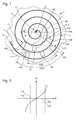
- the curve of the figure 2 shows the variation of the torque as a function of the angle of rotation, we see the breaks in slope at the passage of each point corresponding to an abutment and coupling configuration, as explained below.
- the stop means 11, situated on one of the two turns of the pair 50 comprise two stop stops 13, 14, of interfering trajectory with at least one complementary stop stop 15, situated on the other of the two turns of the same pair 50, that comprise the complementary stop means 12.
- the interference at the extreme stop positions defines a range of limitation of the angular stroke CA of the first turn 51 relative to the second turn 52. This limitation makes it possible to temporarily limit the number of active turns of the spiral 1, when said at least one complementary stop stop 15 bears on one of these two stop stops 13, 14.
- a turn for example the first turn 51 or the second turn 52, comprises at least one radial stop 6 limiting the radial displacement of the first turn 51 relative to the second turn 52.
- This particular coupling is based on the relative radial displacement between the turns. It is however limited to the contraction of the hairspring and therefore to a single direction of rotation of the balance.
- At least one radial abutment 6 comprises a friction surface 61, which is arranged to cooperate with a complementary friction surface 62 that includes the second turn 52 or the first turn 51 respectively.
- the invention also relates to a balance-spring balance spring comprising at least one such spring 1, and having a rocker 7 pivoting about an axis D and to which is fixed the first 3 or second 4 end of the hairspring 1.
- the pivoting amplitude of this balance 7 is less than 360 °.
- the invention also relates to a watch movement 20 comprising such a spring balance 10, and a plate 8 carrying a pin 9 for fixing one of the ends 3, 4 of the spring 1.
- the invention also relates to a timepiece 30 comprising at least one such movement 20, and / or at least one such spring balance 10.
- the system has the advantage of limiting the travel of the balance in both directions of rotation. This limitation is made by modifying the rigidity of the hairspring. This modification of the rigidity can be adapted by the choice of the number and the distribution of the abutment surfaces incorporated in the spiral.
- the inertia of the balance spring system is modified only by the modification of the spiral inertia.
- the anti-gallop system does not disturb the oscillations normal sprung balance, it influences its operation only when exceeding the amplitude of rotation.
Landscapes
- Physics & Mathematics (AREA)
- General Physics & Mathematics (AREA)
- Engineering & Computer Science (AREA)
- Manufacturing & Machinery (AREA)
- Springs (AREA)
Abstract
Description
- L'invention concerne un spiral anti-galop d'horlogerie comportant au moins un brin enroulé entre une première extrémité et une deuxième extrémité et comportant au moins deux couples de spires chacun composé d'une première spire et d'une deuxième spire immédiatement voisines comportant respectivement des moyens d'arrêt et des moyens d'arrêt complémentaires en quinconce les uns avec les autres, et définissant ensemble une course angulaire maximale lors d'un couplage local de ladite première spire et de ladite deuxième spire résultant de la coopération en butée desdits moyens d'arrêt avec lesdits moyens d'arrêt complémentaires lors d'accélérations en contraction ou en extension dudit spiral supérieures à des valeurs de consigne, pour limiter le nombre de spires actives dudit spiral.
- L'invention concerne encore un balancier-spiral d'horlogerie comportant au moins un tel spiral, et comportant un balancier pivotant autour d'un axe et auquel est fixée ladite première ou deuxième extrémité dudit spiral.
- L'invention concerne encore un mouvement d'horlogerie comportant au moins un tel balancier-spiral et une platine portant un piton de fixation d'une des extrémités dudit spiral.
- L'invention concerne encore une pièce d'horlogerie comportant au moins un tel mouvement, ou/et au moins un tel balancier-spiral.
- L'invention concerne le domaine des mécanismes d'horlogerie, et plus particulièrement des organes régulateurs de montres.
- Dans les montres mécaniques, les organes régulateurs, notamment les échappements doivent répondre à plusieurs critères dits « de sécurité ». Une des sécurités, le système anti-galop, vise à empêcher l'extension angulaire du balancier au-delà d'un angle normal de rotation.
- Le problème technique est de concevoir un mécanisme de sécurité, notamment anti-galop, effectuant une limitation de l'angle de pivotement d'un balancier lors d'accélérations trop importantes, en particulier lors de chocs, notamment pour un échappement à détente. Un tel mécanisme anti-galop doit être capable d'agir dans les deux sens de pivotement du balancier, c'est-à-dire aussi bien en extension qu'en contraction du spiral.
- Une solution consiste en la modification de la géométrie du spiral par mise en coopération en butée d'ergots de spires consécutives, de façon à rendre certaines spires inactives, et, ainsi, à modifier la rigidité du spiral et sa réponse aux impulsions. On connaît un tel mécanisme, capable d'effectuer la limitation de la course angulaire du balancier dans les deux sens de pivotement, par le document
EP 2 434 353 A1 au nom de MONTRES BREGUET SA, qui décrit un spiral anti-galop par l'accrochage entre eux de crans appartenant à des spires consécutives, aussi bien en contraction qu'en extension du spiral. La manouvre est efficace, toutefois la reprise de couple reste relativement brusque. - La présente invention vise à améliorer la sécurité, en ne perturbant que très faiblement l'inertie du balancier, en limitant sa course angulaire dans les deux sens de rotation, et en effectuant progressivement la reprise de couple.
- A cet effet, l'invention concerne un spiral anti-galop d'horlogerie comportant au moins un brin enroulé entre une première extrémité et une deuxième extrémité et comportant au moins deux couples de spires chacun composé d'une première spire et d'une deuxième spire immédiatement voisines comportant respectivement des moyens d'arrêt et des moyens d'arrêt complémentaires en quinconce les uns avec les autres, et définissant ensemble une course angulaire maximale lors d'un couplage local de ladite première spire et de ladite deuxième spire résultant de la coopération en butée desdits moyens d'arrêt avec lesdits moyens d'arrêt complémentaires lors d'accélérations en contraction ou en extension dudit spiral supérieures à des valeurs de consigne, pour limiter le nombre de spires actives dudit spiral, caractérisé en ce que au moins deux desdits couples de spires définissent des valeurs de course angulaire différentes, de façon à limiter de façon progressive l'amplitude de pivotement entre lesdites première et deuxième extrémités dudit spiral lors d'accélérations angulaires ou radiales dudit spiral supérieures auxdites valeurs de consigne, de façon à faire coopérer en butée un desdits couples avant l'autre, et donc de modifier progressivement la rigidité résultante dudit spiral, par désactivation ou réactivation successive de certaines de ses spires.
- L'invention concerne encore un balancier-spiral d'horlogerie comportant au moins un tel spiral, et comportant un balancier pivotant autour d'un axe et auquel est fixée ladite première ou deuxième extrémité dudit spiral, caractérisé en ce que l'amplitude de pivotement dudit balancier est inférieure à 360 °.
- L'invention concerne encore un mouvement d'horlogerie comportant au moins un tel balancier-spiral et une platine portant un piton de fixation d'une des extrémités dudit spiral.
- L'invention concerne encore une pièce d'horlogerie comportant au moins un tel mouvement, ou/et au moins un tel balancier-spiral.
- D'autres caractéristiques et avantages de l'invention apparaîtront à la lecture de la description détaillée qui va suivre, en référence aux dessins annexés, où :
- la
figure 1 représente, de façon schématisée et en vue en plan, un spiral anti-galop selon l'invention, destiné à osciller autour d'un axe de pivotement, et attaché par son extrémité extérieure à un piton, et par son extrémité inférieure à une virole fixée à un balancier ; ce spiral comporte des butées réparties en quinconce sur des spires voisines, qui interfèrent les unes avec les autres en cas de choc ou de dépassement d'amplitude, deux jeux de spires voisines entre elles sont ainsi équipées, mais avec des angles de limitation différents entre un premier jeu, plus interne, où l'angle est le plus grand, et un deuxième jeu, plus externe, où l'angle est plus petit ; - la
figure 2 représente un diagramme de couple en fonction de l'angle de rotation du spiral ; - la
figure 3 représente, sous forme d'un schéma-blocs, une pièce d'horlogerie, notamment une montre, comportant un mouvement lequel inclut un balancier-spiral comportant un spiral selon l'invention. - L'invention concerne le domaine des mécanismes d'horlogerie, et plus particulièrement des organes régulateurs de montres.
- La présente invention vise à améliorer la sécurité de tout mécanisme oscillant ou de stockage d'énergie, comportant un ressort spiral, notamment d'un mécanisme balancier-spiral.
- Le principe retenu est de modifier la rigidité résultante du ressort lorsqu'un incident survient, dans des conditions d'utilisation qui diffèrent de la marche normale, et notamment lors de fortes accélérations ou d'un choc.
- La modification de la rigidité du spiral peut avoir d'autres applications, et la présente description, qui concerne une application préférée de cet invention au système anti-galop d'un mécanisme d'échappement, n'est nullement limitative.
- La présente invention, appliquée à un balancier-spiral, vise à limiter l'angle de rotation du balancier dans les montres mécaniques à une valeur donnée, notamment pour des amplitudes supérieures à 360°. La limitation de la course angulaire s'effectue dans les deux sens de rotation et ceci sans modifier l'inertie du balancier. Le balancier-spiral est dit libre durant sa course angulaire normale (par rapport au système anti-galop) par le fait que celui-ci ne provoque aucun choc lors du mouvement normal du balancier-spiral.
- Le principe du système proposé repose sur une modification temporaire de la géométrie du spiral. Lors de l'extension ou contraction du spiral due à la rotation du balancier, un mouvement angulaire et radial relatif entre les spires se produit. Des butées de limitation, composées de deux butées, ainsi qu'un bras de blocage de course, sont implantés sur deux spires consécutives du spiral. Pour un angle de rotation maximal donné, les butées sont placées sur les spires de manière à limiter cette course angulaire relative entre deux spires. Lorsque la butée, selon le sens de rotation, bloque la course du bras de blocage, le spiral perd une spire active et sa rigidité est ainsi modifiée. Ce système de butée repose donc sur le déplacement angulaire relatif entre deux spires.
- La distance entre les butées et le bras de blocage peut être non symétrique.
- Le système selon l'invention limite donc le nombre de spires actives, selon l'angle de rotation, et selon le mouvement des spires du spiral. La rigidité du spiral, en fonction de l'angle de rotation, peut donc être modifiée momentanément, grâce à l'ajout, sur au minimum une paire de spires et au maximum toutes les spires, d'un tel système de butées. La rigidité selon l'amplitude de rotation peut donc être définie par la répartition et le nombre de système de butées répartis sur le spiral. L'invention s'attache à effectuer une limitation progressive de l'angle de rotation par modification progressive de la rigidité résultante du spiral.
- Plusieurs couples de spires sont, selon l'invention, équipés ainsi. Le spiral comporte des butées réparties en quinconce sur des spires voisines, qui interfèrent les unes avec les autres en cas de choc ou de dépassement d'amplitude, au moins deux jeux de spires voisines entre elles sont ainsi équipées, mais avec des angles de limitation différents entre un premier jeu, plus interne, où l'angle est le plus grand, et un deuxième jeu, plus externe, où l'angle est plus petit.
- Dans une réalisation avantageuse mais non limitative, on veille à équilibrer le centre de gravité du spiral. La géométrie, la répartition, position et le nombre des butées nécessitent une conception approfondie, et ce présent document en résume uniquement le principe.
- La fabrication d'un tel spiral repose sur des procédés de micro-fabrication permettant une grande liberté de design planaire. Il est possible de réaliser un tel spiral en technologie silicium. La présente invention ne se limite pas à cette technologie, les procédés « LIGA » et les autres procédés de micro-fabrication couramment utilisés pour les composants d'horlogerie, et en particulier de mécanismes d'échappement, sont utilisables..
- Ainsi, l'invention concerne en particulier un spiral anti-galop d'horlogerie 1 comportant au moins un brin 2 enroulé entre une première extrémité 3 et une deuxième extrémité 4. Ce spiral 1 comporte au moins deux couples de spires 50. Chaque couple 50 est composé d'une première spire 51 et d'une deuxième spire 52 immédiatement voisines comportant respectivement des moyens d'arrêt 11 et des moyens d'arrêt complémentaires 12 en quinconce les uns avec les autres.
- Ces moyens d'arrêt 11 et moyens d'arrêt complémentaires 12 définissent ensemble, pour le couple 50 auquel ils appartiennent, une course angulaire maximale CA lors d'un couplage local de la première spire 51 et de la deuxième spire 52. Ce couplage local résulte de la coopération en butée des moyens d'arrêt 11 avec les moyens d'arrêt complémentaires 12 lors d'accélérations en contraction ou en extension du spiral 1 supérieures à des valeurs de consigne, ou de dépassement d'amplitude lors de la rotation de ce spiral 1, pour limiter le nombre de spires actives du spiral 1.
- Selon l'invention, moins deux de ces couples de spires 50 définissent des valeurs de course angulaire CA différentes, de façon à limiter de façon progressive l'amplitude de pivotement entre les première 3 et deuxième 4 extrémités du spiral, 1 lors d'accélérations angulaires ou radiales du spiral 1 supérieures auxdites valeurs de consigne, de façon à faire coopérer en butée un des couples 50 avant l'autre, et donc de modifier progressivement la rigidité résultante du spiral 1, par désactivation ou réactivation successive de certaines de ses spires 5.
- La courbe de la
figure 2 montre la variation du couple en fonction de l'angle de rotation, on voit les ruptures de pente au passage de chaque point correspondant à une configuration de mise en butée et couplage, comme exposé ci-après. - Dans la variante préférée, et non limitative, illustrée par les
figures 1 et3 . dans chaque couple 50, les moyens d'arrêt 11, situés sur l'une des deux spires du couple 50, comportent deux arrêts de butée 13, 14, de trajectoire interférente avec au moins un arrêt de butée complémentaire 15, situé sur l'autre des deux spires du même couple 50, que comportent les moyens d'arrêt complémentaires 12. L'interférence aux positions de butée extrêmes définit un intervalle de limitation de la course angulaire CA de la première spire 51 par rapport à la deuxième spire 52. Cette limitation permet de limiter momentanément le nombre de spires actives du spiral 1, lorsque ledit au moins un arrêt de butée complémentaire 15 est en appui sur l'un de ces deux arrêts de butée 13, 14. - Dans une variante particulière, visible sur la
figure 1 , en complément des arrêts de butée ménagés sur deux spires antagonistes d'un même couple 50, une spire, par exemple la première spire 51, ou respectivement la deuxième spire 52, comporte au moins une butée radiale 6 limitant le déplacement radial de la première spire 51 par rapport à la deuxième spire 52. Ce couplage particulier se base sur le déplacement radial relatif entre les spires. II est cependant limité à la contraction du spiral et donc à un seul sens de rotation du balancier. - Dans cette même variante particulière, avantageusement au moins une butée radiale 6 comporte une surface de friction 61, qui est agencée pour coopérer avec une surface de friction complémentaire 62 que comporte la deuxième spire 52 ou respectivement la première spire 51.
- Dans une autre variante encore, combinant les arrêts de butée du couple 50 et la butée radiale 6, ce sont les moyens d'arrêt 11 ou les moyens d'arrêt complémentaires 12 qui comportent cette au moins une butée radiale 6.
- L'invention concerne encore un balancier-spiral d'horlogerie 10 comportant au moins un tel spiral 1, et comportant un balancier 7 pivotant autour d'un axe D et auquel est fixée la première 3 ou deuxième 4 extrémité du spiral 1. De préférence, l'amplitude de pivotement de ce balancier 7 est inférieure à 360°.
- L'invention concerne encore un mouvement horloger 20 comportant un tel balancier-spiral 10, et une platine 8 portant un piton 9 de fixation d'une des extrémités 3, 4, du spiral 1.
- L'invention concerne encore un pièce d'horlogerie 30 comportant au moins un tel mouvement 20, ou/et au moins un tel balancier-spiral 10.
- Le système présente l'avantage de limiter la course du balancier dans les deux sens de rotation. Cette limitation est effectuée via la modification de la rigidité du spiral. Cette modification de la rigidité peut être adaptée par le choix du nombre et de la répartition des surfaces de butée incorporées dans le spiral.
- L'inertie du système balancier-spiral n'est modifiée que par la modification de l'inertie du spiral. Le système anti-galop ne perturbe pas les oscillations normales du balancier-spiral, il n'influence sa marche que lors d'un dépassement d'amplitude de rotation.
Claims (8)
- Spiral anti-galop d'horlogerie (1) comportant au moins un brin (2) enroulé entre une première extrémité (3) et une deuxième extrémité (4) et comportant au moins deux couples de spires (50) chacun composé d'une première spire (51) et d'une deuxième spire (52) immédiatement voisines comportant respectivement des moyens d'arrêt (11) et des moyens d'arrêt complémentaires (12) en quinconce les uns avec les autres, et définissant ensemble une course angulaire maximale (CA) lors d'un couplage local de ladite première spire (51) et de ladite deuxième spire (52) résultant de la coopération en butée desdits moyens d'arrêt (11) avec lesdits moyens d'arrêt complémentaires (12) lors d'accélérations en contraction ou en extension dudit spiral (1) supérieures à des valeurs de consigne, pour limiter le nombre de spires actives dudit spiral (1), caractérisé en ce que au moins deux desdits couples de spires (50) définissent des valeurs de course angulaire (CA) différentes, de façon à limiter de façon progressive l'amplitude de pivotement entre lesdites première (3) et deuxième (4) extrémités dudit spiral (1) lors d'accélérations angulaires ou radiales dudit spiral (1) supérieures auxdites valeurs de consigne, de façon à faire coopérer en butée un desdits couples (50) avant l'autre, et donc de modifier progressivement la rigidité résultante dudit spiral (1), par désactivation ou réactivation successive de certaines de ses spires (5).
- Spiral d'horlogerie (1) selon la revendication précédente, caractérisé en ce que, dans chaque dit couple (50), lesdits moyens d'arrêt (11) comportent deux arrêts de butée (13, 14) de trajectoire interférente avec au moins un arrêt de butée complémentaire (15) que comportent lesdits moyens d'arrêt complémentaires (12) pour définir un intervalle de limitation de ladite course angulaire (CA) de ladite première spire (51) par rapport à ladite deuxième spire (52), pour limiter le nombre de spires actives dudit spiral (1) lorsque ledit au moins un arrêt de butée complémentaire (15) est en appui sur l'un desdits deux arrêts de butée (13, 14).
- Spiral d'horlogerie (1) selon la revendication précédente, caractérisé en ce que ladite première spire (51) ou respectivement ladite deuxième spire (52) comporte au moins une butée radiale 6) limitant le déplacement radial de ladite première spire (51) par rapport à ladite deuxième spire (52).
- Spiral d'horlogerie (1) selon la revendication précédente, caractérisé en ce que ladite au moins une butée radiale (6) comporte une surface de friction (61) agencée pour coopérer avec une surface de friction complémentaire (62) que comporte ladite deuxième spire (52) ou respectivement ladite première spire (51).
- Spiral d'horlogerie (1) selon la revendication 3 ou 4, caractérisé en ce que lesdits moyens d'arrêt (11) ou lesdits moyens d'arrêt complémentaires (12) comportent ladite au moins une butée radiale (6).
- Balancier-spiral d'horlogerie (10) comportant au moins un spiral (1) selon l'une des revendications précédentes, et comportant un balancier (7) pivotant autour d'un axe (D) et auquel est fixée ladite première (3) ou deuxième (4) extrémité dudit spiral (1), caractérisé en ce que l'amplitude de pivotement dudit balancier (7) est inférieure à 360°.
- Mouvement horloger (20) comportant un dit balancier-spiral (10) selon la revendication précédente, et une platine (8) portant un piton (9) de fixation d'une des extrémités (3 ; 4) dudit spiral (1).
- Pièce d'horlogerie (30) comportant au moins un mouvement (20) selon la revendication précédente, ou/et au moins un balancier-spiral (10) selon la revendication 6.
Priority Applications (9)
| Application Number | Priority Date | Filing Date | Title |
|---|---|---|---|
| EP12178081.1A EP2690508B1 (fr) | 2012-07-26 | 2012-07-26 | Spiral d'horlogerie |
| CH01170/12A CH706766A2 (fr) | 2012-07-26 | 2012-07-26 | Spiral d'horlogerie anti-galop. |
| TW102125206A TWI602038B (zh) | 2012-07-26 | 2013-07-15 | 用於時計的防跳脫游絲,及具有此游絲的時計彈簧平衡件、時計機芯和時計 |
| KR1020130083501A KR101513797B1 (ko) | 2012-07-26 | 2013-07-16 | 시계 밸런스 스프링 |
| US13/948,626 US8821007B2 (en) | 2012-07-26 | 2013-07-23 | Timepiece balance spring |
| RU2013135097A RU2615595C2 (ru) | 2012-07-26 | 2013-07-25 | Балансирная пружина часов |
| JP2013155241A JP5503788B2 (ja) | 2012-07-26 | 2013-07-26 | 時計のヒゲゼンマイ |
| CN201310320766.3A CN103576528B (zh) | 2012-07-26 | 2013-07-26 | 钟表游丝 |
| HK14107968.7A HK1194492B (en) | 2012-07-26 | 2014-08-04 | Timepiece balance spring |
Applications Claiming Priority (1)
| Application Number | Priority Date | Filing Date | Title |
|---|---|---|---|
| EP12178081.1A EP2690508B1 (fr) | 2012-07-26 | 2012-07-26 | Spiral d'horlogerie |
Publications (2)
| Publication Number | Publication Date |
|---|---|
| EP2690508A1 true EP2690508A1 (fr) | 2014-01-29 |
| EP2690508B1 EP2690508B1 (fr) | 2015-02-25 |
Family
ID=46650387
Family Applications (1)
| Application Number | Title | Priority Date | Filing Date |
|---|---|---|---|
| EP12178081.1A Active EP2690508B1 (fr) | 2012-07-26 | 2012-07-26 | Spiral d'horlogerie |
Country Status (8)
| Country | Link |
|---|---|
| US (1) | US8821007B2 (fr) |
| EP (1) | EP2690508B1 (fr) |
| JP (1) | JP5503788B2 (fr) |
| KR (1) | KR101513797B1 (fr) |
| CN (1) | CN103576528B (fr) |
| CH (1) | CH706766A2 (fr) |
| RU (1) | RU2615595C2 (fr) |
| TW (1) | TWI602038B (fr) |
Cited By (1)
| Publication number | Priority date | Publication date | Assignee | Title |
|---|---|---|---|---|
| EP2884347A1 (fr) * | 2013-12-16 | 2015-06-17 | ETA SA Manufacture Horlogère Suisse | Spiral avec dispositif anti-rapprochement de spires |
Families Citing this family (2)
| Publication number | Priority date | Publication date | Assignee | Title |
|---|---|---|---|---|
| EP2874020B1 (fr) * | 2013-11-15 | 2016-10-26 | Rolex Sa | Système réglant pour mouvement d'horlogerie |
| EP3159748B1 (fr) * | 2015-10-22 | 2018-12-12 | ETA SA Manufacture Horlogère Suisse | Spiral a encombrement reduit a section variable |
Citations (2)
| Publication number | Priority date | Publication date | Assignee | Title |
|---|---|---|---|---|
| US3696687A (en) * | 1971-03-25 | 1972-10-10 | Ametek Inc | Plastic hairspring |
| EP2434353A1 (fr) | 2010-09-28 | 2012-03-28 | Montres Breguet SA | Spiral anti-galop pour échappement d'horlogerie |
Family Cites Families (7)
| Publication number | Priority date | Publication date | Assignee | Title |
|---|---|---|---|---|
| DE2421750A1 (de) | 1974-05-06 | 1975-11-20 | Timex Corp | Insbesondere fuer elektrische uhren vorgesehene spiralfederanordnung |
| EP1791039A1 (fr) * | 2005-11-25 | 2007-05-30 | The Swatch Group Research and Development Ltd. | Spiral en verre athermique pour mouvement d'horlogerie et son procédé de fabrication |
| CH698876B1 (fr) * | 2006-05-17 | 2009-11-30 | Patek Philippe Sa | Ensemble spiral-virole pour mouvement d'horlogerie. |
| EP2196867A1 (fr) | 2008-12-15 | 2010-06-16 | Montres Breguet S.A. | Spiral à élévation de courbe en matériau à base de silicium |
| EP2405312A1 (fr) * | 2010-07-09 | 2012-01-11 | Montres Breguet S.A. | Spiral de balancier à deux niveaux et à centre de masse immobile |
| EP2450757B1 (fr) * | 2010-11-04 | 2014-10-15 | Nivarox-FAR S.A. | Dispositif anti-galop pour mécanisme d'échappement |
| EP2520983A1 (fr) * | 2011-05-03 | 2012-11-07 | Nivarox-FAR S.A. | Barillet comportant des moyens élastiques d'accumulation d'énergie |
-
2012
- 2012-07-26 CH CH01170/12A patent/CH706766A2/fr not_active Application Discontinuation
- 2012-07-26 EP EP12178081.1A patent/EP2690508B1/fr active Active
-
2013
- 2013-07-15 TW TW102125206A patent/TWI602038B/zh active
- 2013-07-16 KR KR1020130083501A patent/KR101513797B1/ko active Active
- 2013-07-23 US US13/948,626 patent/US8821007B2/en active Active
- 2013-07-25 RU RU2013135097A patent/RU2615595C2/ru active
- 2013-07-26 JP JP2013155241A patent/JP5503788B2/ja active Active
- 2013-07-26 CN CN201310320766.3A patent/CN103576528B/zh active Active
Patent Citations (2)
| Publication number | Priority date | Publication date | Assignee | Title |
|---|---|---|---|---|
| US3696687A (en) * | 1971-03-25 | 1972-10-10 | Ametek Inc | Plastic hairspring |
| EP2434353A1 (fr) | 2010-09-28 | 2012-03-28 | Montres Breguet SA | Spiral anti-galop pour échappement d'horlogerie |
Cited By (1)
| Publication number | Priority date | Publication date | Assignee | Title |
|---|---|---|---|---|
| EP2884347A1 (fr) * | 2013-12-16 | 2015-06-17 | ETA SA Manufacture Horlogère Suisse | Spiral avec dispositif anti-rapprochement de spires |
Also Published As
| Publication number | Publication date |
|---|---|
| CN103576528B (zh) | 2016-06-15 |
| KR20140013934A (ko) | 2014-02-05 |
| TWI602038B (zh) | 2017-10-11 |
| EP2690508B1 (fr) | 2015-02-25 |
| TW201411302A (zh) | 2014-03-16 |
| CH706766A2 (fr) | 2014-01-31 |
| RU2615595C2 (ru) | 2017-04-05 |
| RU2013135097A (ru) | 2015-01-27 |
| CN103576528A (zh) | 2014-02-12 |
| US8821007B2 (en) | 2014-09-02 |
| KR101513797B1 (ko) | 2015-04-20 |
| JP5503788B2 (ja) | 2014-05-28 |
| US20140029390A1 (en) | 2014-01-30 |
| HK1194492A1 (zh) | 2014-10-17 |
| JP2014025938A (ja) | 2014-02-06 |
Similar Documents
| Publication | Publication Date | Title |
|---|---|---|
| EP2690507B1 (fr) | Spiral d'horlogerie | |
| EP3548973B1 (fr) | Dispositif pour pièce d'horlogerie, mouvement horloger et pièce d'horlogerie comprenant un tel dispositif | |
| CH713165A2 (fr) | Protection des lames d'un résonateur de montre mécanique en cas de choc. | |
| EP3457221A2 (fr) | Oscillateur horloger a pivot flexible | |
| WO2018095595A1 (fr) | Résonateur rotatif à guidage flexible entretenu par un échappement libre à ancre | |
| EP2455821B1 (fr) | Mobile de transmission d'énergie | |
| EP3561607B1 (fr) | Protection antichoc d'un mécanisme résonateur à guidage flexible rotatif | |
| EP3435173B1 (fr) | Mouvement mécanique avec résonateur rotatif, isochrone, insensible aux positions | |
| EP2781967B1 (fr) | Spiral d'horlogerie | |
| EP2790066B1 (fr) | Cassette de mécanisme d'horlogerie | |
| EP2690508B1 (fr) | Spiral d'horlogerie | |
| EP2690506A1 (fr) | Spiral d'horlogerie anti-galop | |
| EP2948820B1 (fr) | Dispositif de guidage d'arbre d'horlogerie | |
| EP3021173B1 (fr) | Masse oscillante annulaire et pièce d'horlogerie comportant une telle masse oscillante | |
| CH713138A2 (fr) | Protection des lames d'un résonateur de montre mécanique en cas de choc. | |
| EP2790070B1 (fr) | Structure de mécanisme d'horlogerie | |
| EP3179314B1 (fr) | Porte-piton a montage simplifie | |
| CH717880A2 (fr) | Mécanisme résonateur à guidage flexible rotatif avec protection antichoc à butée. | |
| CH706763A2 (fr) | Ensemble horloger comportant un spiral d'horlogerie. | |
| EP2874019B1 (fr) | Courbe terminale pour un spiral entraîné par son extrémité extérieure | |
| CH721479A2 (fr) | Oscillateur pour dispositif régulateur de mouvement horloger, dispositif régulateur de mouvement horloger, mouvement horloger et pièce d'horlogerie | |
| CH706760A2 (fr) | Mécanisme et spiral d'horlogerie anti-galop. | |
| CH711899A2 (fr) | Ensemble de maintien ou d'appui d'un ressort spiral d'horlogerie comportant un piton et un porte-piton. |
Legal Events
| Date | Code | Title | Description |
|---|---|---|---|
| PUAI | Public reference made under article 153(3) epc to a published international application that has entered the european phase |
Free format text: ORIGINAL CODE: 0009012 |
|
| AK | Designated contracting states |
Kind code of ref document: A1 Designated state(s): AL AT BE BG CH CY CZ DE DK EE ES FI FR GB GR HR HU IE IS IT LI LT LU LV MC MK MT NL NO PL PT RO RS SE SI SK SM TR |
|
| AX | Request for extension of the european patent |
Extension state: BA ME |
|
| 17P | Request for examination filed |
Effective date: 20140729 |
|
| RBV | Designated contracting states (corrected) |
Designated state(s): AL AT BE BG CH CY CZ DE DK EE ES FI FR GB GR HR HU IE IS IT LI LT LU LV MC MK MT NL NO PL PT RO RS SE SI SK SM TR |
|
| RIC1 | Information provided on ipc code assigned before grant |
Ipc: G04B 17/26 20060101AFI20140815BHEP Ipc: G04B 17/06 20060101ALI20140815BHEP |
|
| GRAP | Despatch of communication of intention to grant a patent |
Free format text: ORIGINAL CODE: EPIDOSNIGR1 |
|
| INTG | Intention to grant announced |
Effective date: 20141013 |
|
| GRAS | Grant fee paid |
Free format text: ORIGINAL CODE: EPIDOSNIGR3 |
|
| GRAA | (expected) grant |
Free format text: ORIGINAL CODE: 0009210 |
|
| AK | Designated contracting states |
Kind code of ref document: B1 Designated state(s): AL AT BE BG CH CY CZ DE DK EE ES FI FR GB GR HR HU IE IS IT LI LT LU LV MC MK MT NL NO PL PT RO RS SE SI SK SM TR |
|
| REG | Reference to a national code |
Ref country code: GB Ref legal event code: FG4D Free format text: NOT ENGLISH |
|
| REG | Reference to a national code |
Ref country code: CH Ref legal event code: EP |
|
| REG | Reference to a national code |
Ref country code: IE Ref legal event code: FG4D Free format text: LANGUAGE OF EP DOCUMENT: FRENCH |
|
| REG | Reference to a national code |
Ref country code: DE Ref legal event code: R096 Ref document number: 602012005393 Country of ref document: DE Effective date: 20150409 |
|
| REG | Reference to a national code |
Ref country code: AT Ref legal event code: REF Ref document number: 712478 Country of ref document: AT Kind code of ref document: T Effective date: 20150415 Ref country code: CH Ref legal event code: NV Representative=s name: ICB INGENIEURS CONSEILS EN BREVETS SA, CH |
|
| REG | Reference to a national code |
Ref country code: NL Ref legal event code: VDEP Effective date: 20150225 |
|
| REG | Reference to a national code |
Ref country code: AT Ref legal event code: MK05 Ref document number: 712478 Country of ref document: AT Kind code of ref document: T Effective date: 20150225 |
|
| REG | Reference to a national code |
Ref country code: LT Ref legal event code: MG4D |
|
| PG25 | Lapsed in a contracting state [announced via postgrant information from national office to epo] |
Ref country code: NO Free format text: LAPSE BECAUSE OF FAILURE TO SUBMIT A TRANSLATION OF THE DESCRIPTION OR TO PAY THE FEE WITHIN THE PRESCRIBED TIME-LIMIT Effective date: 20150525 Ref country code: LT Free format text: LAPSE BECAUSE OF FAILURE TO SUBMIT A TRANSLATION OF THE DESCRIPTION OR TO PAY THE FEE WITHIN THE PRESCRIBED TIME-LIMIT Effective date: 20150225 Ref country code: ES Free format text: LAPSE BECAUSE OF FAILURE TO SUBMIT A TRANSLATION OF THE DESCRIPTION OR TO PAY THE FEE WITHIN THE PRESCRIBED TIME-LIMIT Effective date: 20150225 Ref country code: FI Free format text: LAPSE BECAUSE OF FAILURE TO SUBMIT A TRANSLATION OF THE DESCRIPTION OR TO PAY THE FEE WITHIN THE PRESCRIBED TIME-LIMIT Effective date: 20150225 Ref country code: SE Free format text: LAPSE BECAUSE OF FAILURE TO SUBMIT A TRANSLATION OF THE DESCRIPTION OR TO PAY THE FEE WITHIN THE PRESCRIBED TIME-LIMIT Effective date: 20150225 Ref country code: HR Free format text: LAPSE BECAUSE OF FAILURE TO SUBMIT A TRANSLATION OF THE DESCRIPTION OR TO PAY THE FEE WITHIN THE PRESCRIBED TIME-LIMIT Effective date: 20150225 |
|
| PG25 | Lapsed in a contracting state [announced via postgrant information from national office to epo] |
Ref country code: GR Free format text: LAPSE BECAUSE OF FAILURE TO SUBMIT A TRANSLATION OF THE DESCRIPTION OR TO PAY THE FEE WITHIN THE PRESCRIBED TIME-LIMIT Effective date: 20150526 Ref country code: IS Free format text: LAPSE BECAUSE OF FAILURE TO SUBMIT A TRANSLATION OF THE DESCRIPTION OR TO PAY THE FEE WITHIN THE PRESCRIBED TIME-LIMIT Effective date: 20150625 Ref country code: LV Free format text: LAPSE BECAUSE OF FAILURE TO SUBMIT A TRANSLATION OF THE DESCRIPTION OR TO PAY THE FEE WITHIN THE PRESCRIBED TIME-LIMIT Effective date: 20150225 Ref country code: RS Free format text: LAPSE BECAUSE OF FAILURE TO SUBMIT A TRANSLATION OF THE DESCRIPTION OR TO PAY THE FEE WITHIN THE PRESCRIBED TIME-LIMIT Effective date: 20150225 Ref country code: AT Free format text: LAPSE BECAUSE OF FAILURE TO SUBMIT A TRANSLATION OF THE DESCRIPTION OR TO PAY THE FEE WITHIN THE PRESCRIBED TIME-LIMIT Effective date: 20150225 |
|
| PG25 | Lapsed in a contracting state [announced via postgrant information from national office to epo] |
Ref country code: NL Free format text: LAPSE BECAUSE OF FAILURE TO SUBMIT A TRANSLATION OF THE DESCRIPTION OR TO PAY THE FEE WITHIN THE PRESCRIBED TIME-LIMIT Effective date: 20150225 |
|
| PG25 | Lapsed in a contracting state [announced via postgrant information from national office to epo] |
Ref country code: SK Free format text: LAPSE BECAUSE OF FAILURE TO SUBMIT A TRANSLATION OF THE DESCRIPTION OR TO PAY THE FEE WITHIN THE PRESCRIBED TIME-LIMIT Effective date: 20150225 Ref country code: RO Free format text: LAPSE BECAUSE OF FAILURE TO SUBMIT A TRANSLATION OF THE DESCRIPTION OR TO PAY THE FEE WITHIN THE PRESCRIBED TIME-LIMIT Effective date: 20150225 Ref country code: CZ Free format text: LAPSE BECAUSE OF FAILURE TO SUBMIT A TRANSLATION OF THE DESCRIPTION OR TO PAY THE FEE WITHIN THE PRESCRIBED TIME-LIMIT Effective date: 20150225 Ref country code: DK Free format text: LAPSE BECAUSE OF FAILURE TO SUBMIT A TRANSLATION OF THE DESCRIPTION OR TO PAY THE FEE WITHIN THE PRESCRIBED TIME-LIMIT Effective date: 20150225 Ref country code: EE Free format text: LAPSE BECAUSE OF FAILURE TO SUBMIT A TRANSLATION OF THE DESCRIPTION OR TO PAY THE FEE WITHIN THE PRESCRIBED TIME-LIMIT Effective date: 20150225 |
|
| REG | Reference to a national code |
Ref country code: DE Ref legal event code: R097 Ref document number: 602012005393 Country of ref document: DE |
|
| PG25 | Lapsed in a contracting state [announced via postgrant information from national office to epo] |
Ref country code: PL Free format text: LAPSE BECAUSE OF FAILURE TO SUBMIT A TRANSLATION OF THE DESCRIPTION OR TO PAY THE FEE WITHIN THE PRESCRIBED TIME-LIMIT Effective date: 20150225 |
|
| PG25 | Lapsed in a contracting state [announced via postgrant information from national office to epo] |
Ref country code: IT Free format text: LAPSE BECAUSE OF FAILURE TO SUBMIT A TRANSLATION OF THE DESCRIPTION OR TO PAY THE FEE WITHIN THE PRESCRIBED TIME-LIMIT Effective date: 20150225 |
|
| PLBE | No opposition filed within time limit |
Free format text: ORIGINAL CODE: 0009261 |
|
| STAA | Information on the status of an ep patent application or granted ep patent |
Free format text: STATUS: NO OPPOSITION FILED WITHIN TIME LIMIT |
|
| 26N | No opposition filed |
Effective date: 20151126 |
|
| PG25 | Lapsed in a contracting state [announced via postgrant information from national office to epo] |
Ref country code: MC Free format text: LAPSE BECAUSE OF FAILURE TO SUBMIT A TRANSLATION OF THE DESCRIPTION OR TO PAY THE FEE WITHIN THE PRESCRIBED TIME-LIMIT Effective date: 20150225 Ref country code: SI Free format text: LAPSE BECAUSE OF FAILURE TO SUBMIT A TRANSLATION OF THE DESCRIPTION OR TO PAY THE FEE WITHIN THE PRESCRIBED TIME-LIMIT Effective date: 20150225 |
|
| PG25 | Lapsed in a contracting state [announced via postgrant information from national office to epo] |
Ref country code: LU Free format text: LAPSE BECAUSE OF FAILURE TO SUBMIT A TRANSLATION OF THE DESCRIPTION OR TO PAY THE FEE WITHIN THE PRESCRIBED TIME-LIMIT Effective date: 20150726 |
|
| REG | Reference to a national code |
Ref country code: IE Ref legal event code: MM4A |
|
| REG | Reference to a national code |
Ref country code: FR Ref legal event code: PLFP Year of fee payment: 5 |
|
| PG25 | Lapsed in a contracting state [announced via postgrant information from national office to epo] |
Ref country code: IE Free format text: LAPSE BECAUSE OF NON-PAYMENT OF DUE FEES Effective date: 20150726 |
|
| PG25 | Lapsed in a contracting state [announced via postgrant information from national office to epo] |
Ref country code: MT Free format text: LAPSE BECAUSE OF FAILURE TO SUBMIT A TRANSLATION OF THE DESCRIPTION OR TO PAY THE FEE WITHIN THE PRESCRIBED TIME-LIMIT Effective date: 20150225 |
|
| PG25 | Lapsed in a contracting state [announced via postgrant information from national office to epo] |
Ref country code: HU Free format text: LAPSE BECAUSE OF FAILURE TO SUBMIT A TRANSLATION OF THE DESCRIPTION OR TO PAY THE FEE WITHIN THE PRESCRIBED TIME-LIMIT; INVALID AB INITIO Effective date: 20120726 Ref country code: SM Free format text: LAPSE BECAUSE OF FAILURE TO SUBMIT A TRANSLATION OF THE DESCRIPTION OR TO PAY THE FEE WITHIN THE PRESCRIBED TIME-LIMIT Effective date: 20150225 Ref country code: BG Free format text: LAPSE BECAUSE OF FAILURE TO SUBMIT A TRANSLATION OF THE DESCRIPTION OR TO PAY THE FEE WITHIN THE PRESCRIBED TIME-LIMIT Effective date: 20150225 |
|
| REG | Reference to a national code |
Ref country code: FR Ref legal event code: PLFP Year of fee payment: 6 |
|
| PG25 | Lapsed in a contracting state [announced via postgrant information from national office to epo] |
Ref country code: CY Free format text: LAPSE BECAUSE OF FAILURE TO SUBMIT A TRANSLATION OF THE DESCRIPTION OR TO PAY THE FEE WITHIN THE PRESCRIBED TIME-LIMIT Effective date: 20150225 |
|
| PG25 | Lapsed in a contracting state [announced via postgrant information from national office to epo] |
Ref country code: BE Free format text: LAPSE BECAUSE OF NON-PAYMENT OF DUE FEES Effective date: 20150731 |
|
| REG | Reference to a national code |
Ref country code: FR Ref legal event code: PLFP Year of fee payment: 7 |
|
| PG25 | Lapsed in a contracting state [announced via postgrant information from national office to epo] |
Ref country code: TR Free format text: LAPSE BECAUSE OF FAILURE TO SUBMIT A TRANSLATION OF THE DESCRIPTION OR TO PAY THE FEE WITHIN THE PRESCRIBED TIME-LIMIT Effective date: 20150225 Ref country code: PT Free format text: LAPSE BECAUSE OF FAILURE TO SUBMIT A TRANSLATION OF THE DESCRIPTION OR TO PAY THE FEE WITHIN THE PRESCRIBED TIME-LIMIT Effective date: 20150225 Ref country code: MK Free format text: LAPSE BECAUSE OF FAILURE TO SUBMIT A TRANSLATION OF THE DESCRIPTION OR TO PAY THE FEE WITHIN THE PRESCRIBED TIME-LIMIT Effective date: 20150225 |
|
| PG25 | Lapsed in a contracting state [announced via postgrant information from national office to epo] |
Ref country code: AL Free format text: LAPSE BECAUSE OF FAILURE TO SUBMIT A TRANSLATION OF THE DESCRIPTION OR TO PAY THE FEE WITHIN THE PRESCRIBED TIME-LIMIT Effective date: 20150225 |
|
| P01 | Opt-out of the competence of the unified patent court (upc) registered |
Effective date: 20230611 |
|
| PGFP | Annual fee paid to national office [announced via postgrant information from national office to epo] |
Ref country code: GB Payment date: 20250619 Year of fee payment: 14 |
|
| PGFP | Annual fee paid to national office [announced via postgrant information from national office to epo] |
Ref country code: FR Payment date: 20250620 Year of fee payment: 14 |
|
| PGFP | Annual fee paid to national office [announced via postgrant information from national office to epo] |
Ref country code: DE Payment date: 20250620 Year of fee payment: 14 |
|
| PGFP | Annual fee paid to national office [announced via postgrant information from national office to epo] |
Ref country code: CH Payment date: 20250801 Year of fee payment: 14 |