EP2690327B1 - Hydraulic directional valve - Google Patents
Hydraulic directional valve Download PDFInfo
- Publication number
- EP2690327B1 EP2690327B1 EP13002664.4A EP13002664A EP2690327B1 EP 2690327 B1 EP2690327 B1 EP 2690327B1 EP 13002664 A EP13002664 A EP 13002664A EP 2690327 B1 EP2690327 B1 EP 2690327B1
- Authority
- EP
- European Patent Office
- Prior art keywords
- valve
- chamber
- seat bore
- valve seat
- line
- Prior art date
- Legal status (The legal status is an assumption and is not a legal conclusion. Google has not performed a legal analysis and makes no representation as to the accuracy of the status listed.)
- Active
Links
Images

Classifications
-
- E—FIXED CONSTRUCTIONS
- E05—LOCKS; KEYS; WINDOW OR DOOR FITTINGS; SAFES
- E05F—DEVICES FOR MOVING WINGS INTO OPEN OR CLOSED POSITION; CHECKS FOR WINGS; WING FITTINGS NOT OTHERWISE PROVIDED FOR, CONCERNED WITH THE FUNCTIONING OF THE WING
- E05F3/00—Closers or openers with braking devices, e.g. checks; Construction of pneumatic or liquid braking devices
- E05F3/04—Closers or openers with braking devices, e.g. checks; Construction of pneumatic or liquid braking devices with liquid piston brakes
- E05F3/12—Special devices controlling the circulation of the liquid, e.g. valve arrangement
-
- E—FIXED CONSTRUCTIONS
- E05—LOCKS; KEYS; WINDOW OR DOOR FITTINGS; SAFES
- E05F—DEVICES FOR MOVING WINGS INTO OPEN OR CLOSED POSITION; CHECKS FOR WINGS; WING FITTINGS NOT OTHERWISE PROVIDED FOR, CONCERNED WITH THE FUNCTIONING OF THE WING
- E05F3/00—Closers or openers with braking devices, e.g. checks; Construction of pneumatic or liquid braking devices
- E05F3/22—Additional arrangements for closers, e.g. for holding the wing in opened or other position
- E05F3/223—Hydraulic power-locks, e.g. with electrically operated hydraulic valves
-
- F—MECHANICAL ENGINEERING; LIGHTING; HEATING; WEAPONS; BLASTING
- F16—ENGINEERING ELEMENTS AND UNITS; GENERAL MEASURES FOR PRODUCING AND MAINTAINING EFFECTIVE FUNCTIONING OF MACHINES OR INSTALLATIONS; THERMAL INSULATION IN GENERAL
- F16K—VALVES; TAPS; COCKS; ACTUATING-FLOATS; DEVICES FOR VENTING OR AERATING
- F16K1/00—Lift valves or globe valves, i.e. cut-off apparatus with closure members having at least a component of their opening and closing motion perpendicular to the closing faces
- F16K1/32—Details
- F16K1/54—Arrangements for modifying the way in which the rate of flow varies during the actuation of the valve
-
- F—MECHANICAL ENGINEERING; LIGHTING; HEATING; WEAPONS; BLASTING
- F16—ENGINEERING ELEMENTS AND UNITS; GENERAL MEASURES FOR PRODUCING AND MAINTAINING EFFECTIVE FUNCTIONING OF MACHINES OR INSTALLATIONS; THERMAL INSULATION IN GENERAL
- F16K—VALVES; TAPS; COCKS; ACTUATING-FLOATS; DEVICES FOR VENTING OR AERATING
- F16K31/00—Actuating devices; Operating means; Releasing devices
- F16K31/02—Actuating devices; Operating means; Releasing devices electric; magnetic
- F16K31/06—Actuating devices; Operating means; Releasing devices electric; magnetic using a magnet, e.g. diaphragm valves, cutting off by means of a liquid
- F16K31/0603—Multiple-way valves
- F16K31/0624—Lift valves
- F16K31/0627—Lift valves with movable valve member positioned between seats
-
- E—FIXED CONSTRUCTIONS
- E05—LOCKS; KEYS; WINDOW OR DOOR FITTINGS; SAFES
- E05Y—INDEXING SCHEME RELATING TO HINGES OR OTHER SUSPENSION DEVICES FOR DOORS, WINDOWS OR WINGS AND DEVICES FOR MOVING WINGS INTO OPEN OR CLOSED POSITION, CHECKS FOR WINGS AND WING FITTINGS NOT OTHERWISE PROVIDED FOR, CONCERNED WITH THE FUNCTIONING OF THE WING
- E05Y2900/00—Application of doors, windows, wings or fittings thereof
- E05Y2900/10—Application of doors, windows, wings or fittings thereof for buildings or parts thereof
- E05Y2900/13—Application of doors, windows, wings or fittings thereof for buildings or parts thereof characterised by the type of wing
- E05Y2900/132—Doors
Definitions
- the present invention relates to a hydraulic directional control valve, in particular a 3/2-way valve with a ball seat and a conical seat.
- the invention further relates to a door operator for moving a door leaf, comprising the hydraulic directional control valve.
- 3/2-way valves have three fluid connections and two switching positions. Most directional valves are designed as slide valves. It is not absolutely necessary to have an absolutely tight seat as a pump feeds. The relationship to working volume flow and leakage is irrelevant. However, with door actuators seat valves are executed because the ratio of working volume flow and leakage must be optimal or very dense.
- the valve partially uses a valve lifter to open and close the seal seats. The valve lifter is moved by an electromagnet, a control pressure or a mechanical actuator.
- various door operators in particular door closers, power door closers and door operators. Many door operators have a memory spring, in particular a closing spring on. In the compressed storage spring, the energy for moving the door is stored, for example, for an emergency.
- the storage spring is compressed over several days or months and blocked by a hydraulic lock-up space.
- the hydraulic pressure is released from the lock chamber, so that the storage spring can relax.
- the hydraulic valve used must ensure that the pressure in the lock chamber is kept leak-free for a very long time. In an emergency, a safe opening of the valve and switching on the hydraulic damping must be ensured.
- a hydraulic directional control valve comprising a valve housing and a valve chamber integrated in the valve housing.
- the valve chamber has a first valve seat bore as a connection to a first line P, a second valve seat bore as a connection to a second line A and a free opening to a third line T.
- the first line P is connected, for example, with the lock space for a storage spring in a door operator.
- the second line A is used, for example, the damping of a closing movement of the door operator and the third line T is usually the tank line.
- the directional control valve comprises an actuating mechanism and a valve tappet movable by the actuating mechanism and partially arranged in the valve chamber.
- the valve stem has within the valve chamber one of the first valve seat bore facing convex surface as the first sealing surface and one of the second valve seat bore facing conical surface as the second sealing surface. Depending on the position of the valve stem, either the first valve seat bore is closed by the first sealing surface or the second valve seat bore by the second sealing surface.
- the actuating mechanism for example an electromagnet, is designed such that it presses the valve tappet or the first sealing surface onto the first valve seat bore with the least possible absorption of energy and thus closes the first line P leak-free over a long period of time. Nevertheless, it must be ensured that, if necessary, the valve tappet can be moved in the closing direction of the second valve seat bore, so that the second sealing surface comes to rest on the second valve seat bore.
- the valve chamber is divided into a stowage chamber and a main chamber. By configuring the outer contour of the valve tappet and by configuring the inner contour of the valve chamber, this subdivision into the stowage chamber and the main chamber takes place.
- the stowage chamber is facing the first valve seat bore and is thus located between the first valve seat bore and the valve stem.
- the narrowest point of the first valve seat bore is referred to as a first flow cross-sectional area in the first valve seat bore.
- This first flow cross-sectional area in the first valve seat bore is larger than a further flow cross-sectional area after a minimum lifting of the first sealing surface from the first valve seat bore.
- This further flow cross-sectional area is defined by the flow from the stagnation chamber into the main chamber or directly from the stagnation chamber into the third line T.
- the first flow cross-section in the form of a bore is larger than the further flow cross-sectional area in the form of an annular gap, at least after the opening of the tappet.
- the storage chamber can be formed by a shoulder on the outer contour of the valve stem and / or by a shoulder on the inner contour of the valve chamber.
- the valve chamber and / or the valve tappet are rotationally symmetrical, so that the further flow cross-sectional area is in particular an annular surface.
- the plunger moves after the minimum lifting of the first sealing surface of the first valve seat bore further in the closing direction of the second valve seat bore.
- the decisive factor is that the further flow cross-sectional area is extremely small only in the closed position of the first valve seat bore and at the minimum lift-off.
- the further flow cross-sectional area is larger, for example by driving over control edges or retracting the tank bore, so that a sufficiently large flow cross section for the fluid flow from the first line P through the valve chamber into the third line T is possible.
- the further flow cross-sectional area is at least as large as the first flow cross-sectional area in the first valve seat bore.
- a disc is formed on the valve stem.
- This disc can be made integral with the valve lifter or mounted on the valve lifter.
- the outer contour of the disc is fully circumferentially on the inner contour of the valve chamber. This results in the subdivision of the valve chamber in the storage chamber and in the main chamber.
- This fully circumferential concerns of the disc on the inner contour of the valve chamber is given in the closed state of the first valve seat bore and at the minimum lifting.
- the disc is no longer fully circumferentially against the inner contour of the valve chamber.
- the free opening to the third conduit T is run over, so that an unimpeded fluid flow between the first conduit P and the third conduit T via the valve chamber is possible.
- the full-circumferential concerns of the disc on the inner contour of the valve chamber is made fluid-tight.
- the disc comprises a seal or the disc itself is designed as a seal.
- a return spring is provided for moving the valve stem in the closing direction of the second valve seat bore.
- the actuating mechanism is designed so that it moves the valve stem in the closing direction of the first valve seat bore.
- the actuating mechanism is designed in particular as an electromagnet.
- the valve stem extends out of the valve chamber through the second valve seat bore to the actuating mechanism.
- the actuating mechanism is designed so that it presses the first sealing surface on the first valve seat bore in the energized state.
- the plunger can be moved in the closing direction of the second valve seat bore. This is done primarily by a sufficient pressure in the first line P.
- the stagnation chamber fills with pressure or Energybeetzmanntem fluid from the first line P.
- the convex surface of the first sealing surface is preferably formed by a ball.
- the ball is inserted into the remaining part of the valve lifter. In particular, by using the ball a leak-free sealing of the first valve seat bore is possible.
- the second sealing surface is particularly preferably designed as a cone ring surface.
- the invention further comprises a door operator for moving a door leaf.
- the door operator is preferably designed as a door closer, power door closer or door drive.
- the door operator comprises a housing and a housing arranged in the drive unit with an output shaft.
- the output shaft is connected to the door leaf.
- the output unit is used to implement the rotational movement of the output shaft in a linear motion.
- a storage spring is arranged in the housing. This storage spring acts on the drive unit. The storage spring is used to store a closing or opening energy for the door leaf.
- a hydraulic lock space is formed in the housing.
- the lock space serves to block the contracted storage spring.
- a hydraulic damping chamber for damping the movement of the drive unit is formed in the housing.
- the storage spring acts on one side of the drive unit and the damping chamber is formed on the other side of the drive unit.
- the door operator according to the invention further comprises one of the hydraulic directional control valves just described, in particular designed as a hydraulic 3/2-way solenoid valve.
- the first line P is connected to the lock chamber.
- the second line A is connected to the damping chamber.
- the third line T is connected to a tank volume within the door operator.
- the storage spring When the door is open, the storage spring is contracted and blocked by the hydraulic lock space. As a result, the door is fixed in its open position or can be moved manually via a freewheel arrangement in the closing direction. It is crucial that over the lock space, the storage spring remains contracted and thus the energy of the storage spring for safe closing of the door in an emergency is available.
- the lock chamber is connected via the first line P with the first valve seat bore.
- the actuating mechanism is energized and thus pushes the valve stem and the first sealing surface against the first valve seat bore.
- the actuating mechanism is de-energized, so that via the return spring and pressure in the lock chamber of the valve stem in the direction of the second valve seat bore is moved.
- a damping mechanism for example a throttle valve between the hydraulic damping chamber and the tank space, can act.
- the second line is simultaneously opened to prevent pressure build-up in a further pressure chamber.
- the second line is closed safely and very quickly in the shortest possible time to allow pressure build-up and thus a damping function in the other pressure chamber.
- the barrage or stowage chamber is there, after switching off the first stage, the second stage as possible simultaneously, and above all safe to close. A malfunction of the second stage would prevent a damping of the door movement and injury to the user would result.
- the actuating mechanism in particular designed as an electromagnet, should work as little power as possible due to the long energization periods. A very low power consumption also reduces the heating of the bobbin of the electromagnet.
- the entire valve function must manage with the smallest possible switching and clamping forces. For this reason, the flow cross-sectional areas in the valve seat bores are made extremely small. Preferably, the smallest diameter in the first valve seat bore is at most 1 mm. Such small cross sections can be readily sealed with ball or Kegelventil stressesn against very high pressures with very small switching or holding forces.
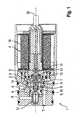
- FIGS. 1 to 4 a first embodiment of the hydraulic directional control valve 1, designed as a 3/2-way solenoid valve, explained in detail.
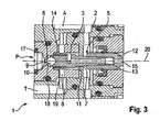
- the figures each show sectional views of the hydraulic directional control valve 1. Die Figures 3 and 4 are enlarged views FIG. 1 ,
- the directional control valve 1 comprises a valve housing 2 and a valve chamber 2 formed in the valve housing 2.
- the valve housing 2 is composed of a plurality of inserts screwed into one another and sealed.
- three terminals are formed: a first line P, a second line A and a third line T.
- the first line P is also referred to as a pressure line.
- the second line A is also referred to as working line.
- the third line T leads in particular to a tank.
- the directional control valve 1 comprises an actuating mechanism, designed as an electromagnet, and a valve tappet 5.
- the actuating mechanism 4 serves to move the valve tappet 5.
- the valve tappet 5 is displaced in a linear movement along a longitudinal axis 20.
- a first valve seat bore 6 is formed as a connection to the first line P. Furthermore, a second valve seat bore 7 is formed as a connection to the second line A. Between the first valve seat bore 6 and the second valve seat bore 7 is a free opening 8 in the valve chamber 3 as a connection to the third line T.
- the valve stem 5 is partially disposed in the valve chamber 3. To facilitate assembly of the valve stem 5 is formed in two parts and consists of a first part 12 which projects into the actuating mechanism 4 and a second part 13, which projects through the second valve seat bore 7 into the valve chamber 3. The two parts 12, 13 are firmly screwed together. For pressure equalization, a connecting channel 15 is provided in the valve stem 5.
- the ball 10 is a first sealing surface 9, formed as a convex surface, is.
- This first sealing surface 9 is the first valve seat bore 6 faces.
- a first valve seat is formed by the first valve seat bore 6 and the first sealing surface 9.
- a second sealing surface 11, designed as a cone ring surface, is arranged on the valve tappet 5.
- the second sealing surface 11 forms, together with the second valve seat bore 7, a second valve seat.
- the actuating mechanism 4 designed as an electromagnet, comprises a coil 16, which can be energized and thus moves the valve stem 5.
- the valve stem 5 in the energized state of the coil 16, the valve stem 5 as shown in FIG FIG. 1 pressed to the left, so that the first sealing surface 9, the first valve seat bore 6 seals.
- a return spring 14 is disposed in the valve chamber 3.
- FIG. 1 The Figures 3 and 4 show enlarged views FIG. 1 , In Figure 3 it can be seen that in the closed position of the first valve seat bore and at a minimum lifting of the first sealing surface 9 of the first valve seat bore 6, the valve chamber 3 is divided into a storage chamber 18 and a main chamber 19. The storage chamber 18 is the first valve seat bore 6 facing.
- FIG. 4 shows a first diameter 21 defining the first flow cross-sectional area in the first valve seat bore 6. Furthermore, a second diameter 22 of the storage chamber 18 and a third diameter 23 of the main chamber 19 are shown.
- the valve stem 5 has a fourth diameter 24 on its side facing the first valve seat bore 6.
- the fourth diameter 24 corresponds approximately to the second diameter 22.
- the minimum difference between the second diameter 22 and the fourth diameter 24 defines the flow cross-sectional area of the fluid flow from the surge chamber 18 into the main chamber 19. This flow cross-sectional area is extremely small or equal to zero. It is crucial that this flow cross-sectional area is smaller than the flow cross-sectional area defined by the first diameter 21.
- the second diameter 22 of the storage chamber 18 is substantially larger than the first diameter 21, so that here is a sufficiently large area for actuating the valve stem 5 is available.
- the second diameter 22 is at least twice as large as the first diameter 21. This results in a sufficient restoring force which moves the valve stem 5 against mass inertia and friction quickly and safely in the second stage.
- the third diameter 23 is at least 20% larger than the second diameter 22, so that a sufficient flow between the first line P and the tank line T is possible.
- FIG. 4 further shows a first length 25 and a second length 26.
- the first length 25 indicates the length of the "minimum lift off" of the first sealing surface 9 from the first valve seat bore 6. During this "minimum lift off", the flow of fluid from the surge chamber 18 into the Main chamber 19 largely suppressed, so that the pressure builds up in the storage chamber 18.
- the second length 26 defines the largest possible movement of the valve stem 5. The first length 25 is smaller than the second length 26th
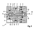
- FIG. 5 shows a detail of the second embodiment, like him FIG. 3 with respect to the first embodiment.
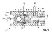
- FIG. 6 shows an enlarged picture FIG. 5 ,
- the division of the valve chamber 3 into the storage chamber 18 and the main chamber 19 is effected by a disc 27 as part of the valve stem 5.
- this disc 27 is a fluid-tight Sealing to the inner wall of the valve chamber 3 out possible.
- the valve chamber 3 may be formed in the second embodiment with a uniform second diameter 22.
- the "minimum lifting" is in turn defined by the first length 25.
- the disc 26 passes over the third line T, so that an approximately free fluid flow between the first line P and the third Line T is possible.
- the invention provides an additional effective space (storage chamber 18) in the valve chamber 3, with which the high liquid energy of the prestressed hydraulic medium from the first conduit P can be used to return the valve stem 5 and the coil armature.
- valve stem 5 After switching off the electromagnet opens by the falling clamping force of the valve stem 5 of the ball valve seat 6, 9, whereby a small amount of the biased hydraulic fluid from the first conduit P, for example, the lock chamber of a door operator, can flow into the storage chamber 18. Another outflow into the third line T or the tank, but is not immediately possible, but the hydraulic fluid is initially dammed in the storage chamber 18.
- the high energy potential of the prestressed fluid over a significantly larger compared to the surface of the first valve seat bore 6 surface defined by the second diameter 22 on the end face of the valve stem 5 for the very fast and safe return of the valve stem 5 and Spool anchor exploited.
- the valve stem 5 is used here simultaneously as a working piston for applying the actuating or switching forces.
- the extent of the positive overlap, ie the first length 25, until the release of the tank drain via the third line T is adjusted depending on the movement of the valve stem 5 to the concern of the second sealing surface 11 on the second valve seat bore 7 with control edges 28. After passing over the control edges 28, the fluid flow from the first line P to the third line T is approximately free and the remaining, clamped hydraulic oil from the first line P can flow freely into the third line T.
- This process takes place in fractions of a second and avoids undefined switching states or intermediate positions of the directional control valve 1.
- the high restoring forces generated in the stagnation chamber 18 also result in stiff valve tappets 5, e.g. at unfavorable tolerances of the components to each other, safely and without delay brought into the respective other switching position.
- sealing friction can be compensated.
- the inertia of the relatively heavy magnet armature is overcome by the high power potential sovereign.
- the disc 27 can be used according to the second embodiment.
- the fluid pressure in the stagnation chamber 18 strikes a kind of baffle plate (disc 26), which only after completed Valve Stem Hub freewheeling the drain hole to the third line T.
- disc 26 due to the disc 26 can be spoken of a "dense" system.
- leakage between the second diameter 22 and the fourth diameter 24 is tolerated.
- the directional control valve 1 described is particularly applicable to a door closer mechanism with storage spring. After a single preload by hand over the door, by an internal motor-pump unit, or by an electromechanically acting gear, the accumulator spring is held hydraulically stretched over the lock chamber. After switching off the holding device, the stored energy can be used from the storage spring for a secure closure of the door in case of emergency or need.
- the construction shown the described directional control valve 1 can also be used in many other areas.
- the application of the invention shown may be advantageous and useful.
Description
Vorliegende Erfindung betrifft ein hydraulisches Wegeventil, insbesondere ein 3/2-Wegeventil mit einem Kugelsitz und einem Kegelsitz. Die Erfindung betrifft ferner einen Türbetätiger zum Bewegen eines Türflügels, umfassend das hydraulische Wegeventil.The present invention relates to a hydraulic directional control valve, in particular a 3/2-way valve with a ball seat and a conical seat. The invention further relates to a door operator for moving a door leaf, comprising the hydraulic directional control valve.
3/2-Wegeventile weisen drei Fluidanschlüsse und zwei Schaltstellungen auf. Meist werden Wegeventile als Schieberventile ausgeführt. Dabei ist ein absolut dichter Sitz nicht unbedingt notwendig, da eine Pumpe nachfördert. Das Verhältnis zu Arbeitsvolumenstrom und Leckage ist dabei unerheblich. Bei Türbetätigern jedoch werden Sitzventile ausgeführt, da das Verhältnis von Arbeitsvolumenstrom und Leckage optimal, bzw. sehr dicht sein muss. Im Ventil wird zum Teil ein Ventilstößel zum Öffnen und Schließen der Dichtsitze verwendet. Der Ventilstößel wird über einen Elektromagneten, einen Steuerdruck oder ein mechanisches Stellglied bewegt. Des Weiteren kennt der Stand der Technik verschiedene Türbetätiger, insbesondere Türschließer, Servotürschließer und Türantriebe. Viele Türbetätiger weisen eine Speicherfeder, insbesondere eine Schließerfeder, auf. In der komprimierten Speicherfeder wird die Energie zum Bewegen des Türflügels, beispielsweise für einen Notfall, gespeichert. Dabei ist die Speicherfeder über mehrere Tage oder Monate komprimiert und durch einen hydraulischen Sperrraum blockiert. Im Notfall kann ein Bewegen der Türe vonnöten sein. In diesem Fall wird der Hydraulikdruck aus dem Sperrraum abgelassen, so dass sich die Speicherfeder entspannen kann. Beim Entspannen wirkt die Speicherfeder auf eine Antriebseinheit im Türbetätiger und somit über die Abtriebswelle auf den Türflügel. Das verwendete Hydraulikventil muss sicherstellen, dass der Druck im Sperrraum über eine sehr lange Zeit leckagefrei gehalten wird. Im Notfall muss ein sicheres Öffnen des Ventils und ein Einschalten der hydraulischen Dämpfung gewährleistet werden.3/2-way valves have three fluid connections and two switching positions. Most directional valves are designed as slide valves. It is not absolutely necessary to have an absolutely tight seat as a pump feeds. The relationship to working volume flow and leakage is irrelevant. However, with door actuators seat valves are executed because the ratio of working volume flow and leakage must be optimal or very dense. The valve partially uses a valve lifter to open and close the seal seats. The valve lifter is moved by an electromagnet, a control pressure or a mechanical actuator. Furthermore, the prior art knows various door operators, in particular door closers, power door closers and door operators. Many door operators have a memory spring, in particular a closing spring on. In the compressed storage spring, the energy for moving the door is stored, for example, for an emergency. The storage spring is compressed over several days or months and blocked by a hydraulic lock-up space. In an emergency, it may be necessary to move the door. In this case, the hydraulic pressure is released from the lock chamber, so that the storage spring can relax. When relaxing the memory spring acts on a drive unit in the door operator and thus on the output shaft on the door leaf. The hydraulic valve used must ensure that the pressure in the lock chamber is kept leak-free for a very long time. In an emergency, a safe opening of the valve and switching on the hydraulic damping must be ensured.
In der
Es ist Aufgabe vorliegender Erfindung, ein hydraulisches Wegeventil bereitzustellen, das bei kostengünstiger Herstellung und bei wartungsarmem Betrieb ein möglichst leckagefreies Abdichten einer ersten Leitung und ein zuverlässiges Öffnen dieser ersten Leitung ermöglicht. Des Weiteren ist es Aufgabe vorliegender Erfindung, einen Türbetätiger mit dem hydraulischen Wegeventil bereitzustellen.It is an object of the present invention to provide a hydraulic directional control valve which, with cost-effective production and low-maintenance operation, enables sealing of a first line which is as leak-free as possible and reliable opening of this first line. Furthermore, it is an object of the present invention to provide a door operator with the hydraulic directional control valve.
Die Lösung der Aufgabe erfolgt durch die Merkmale des unabhängigen Anspruchs . Die abhängigen Ansprüche haben bevorzugte Weiterbildungen der Erfindung zum Gegenstand.The object is achieved by the features of the independent claim. The dependent claims have preferred embodiments of the invention the subject.
Somit wird die Erfindung gelöst durch ein hydraulisches Wegeventil, umfassend ein Ventilgehäuse und eine in das Ventilgehäuse integrierte Ventilkammer. Die Ventilkammer weist eine erste Ventilsitzbohrung als Verbindung zu einer ersten Leitung P, eine zweite Ventilsitzbohrung als Verbindung zu einer zweiten Leitung A und eine freie Öffnung zu einer dritten Leitung T auf. Die erste Leitung P wird beispielsweise mit dem Sperrraum für eine Speicherfeder in einem Türbetätiger verbunden. Die zweite Leitung A dient beispielsweise der Dämpfung einer Schließbewegung des Türbetätigers und die dritte Leitung T ist üblicherweise die Tankleitung. Mit dem erfindungsgemäßen Wegeventil muss nun die erste Leitung P dauerhaft leckagefrei abgesperrt werden. Hierzu umfasst das Wegeventil einen Betätigungsmechanismus und einen durch den Betätigungsmechanismus bewegbaren und teilweise in der Ventilkammer angeordneten Ventilstößel. Der Ventilstößel weist innerhalb der Ventilkammer eine der ersten Ventilsitzbohrung zugewandte konvexe Oberfläche als erste Dichtfläche und eine der zweiten Ventilsitzbohrung zugewandte Kegelfläche als zweite Dichtfläche auf. Je nach Stellung des Ventilstößels ist wahlweise die erste Ventilsitzbohrung durch die erste Dichtfläche oder die zweite Ventilsitzbohrung durch die zweite Dichtfläche verschlossen.Thus, the invention is achieved by a hydraulic directional control valve, comprising a valve housing and a valve chamber integrated in the valve housing. The valve chamber has a first valve seat bore as a connection to a first line P, a second valve seat bore as a connection to a second line A and a free opening to a third line T. The first line P is connected, for example, with the lock space for a storage spring in a door operator. The second line A is used, for example, the damping of a closing movement of the door operator and the third line T is usually the tank line. With the directional valve according to the invention now the first line P must be shut off permanently leak-free. For this purpose, the directional control valve comprises an actuating mechanism and a valve tappet movable by the actuating mechanism and partially arranged in the valve chamber. The valve stem has within the valve chamber one of the first valve seat bore facing convex surface as the first sealing surface and one of the second valve seat bore facing conical surface as the second sealing surface. Depending on the position of the valve stem, either the first valve seat bore is closed by the first sealing surface or the second valve seat bore by the second sealing surface.
Der Betätigungsmechanismus, beispielsweise ein Elektromagnet, ist so ausgebildet, dass er mit möglichst wenig Energieaufnahme den Ventilstößel bzw. die erste Dichtfläche auf die erste Ventilsitzbohrung drückt und somit die erste Leitung P über einen langen Zeitraum leckagefrei schließt. Trotzdem muss sichergestellt werden, dass bei Bedarf der Ventilstößel in Schließrichtung der zweiten Ventilsitzbohrung bewegt werden kann, so dass die zweite Dichtfläche auf der zweiten Ventilsitzbohrung zur Anlage kommt. Um dies zu gewährleisten, ist die Ventilkammer unterteilt in eine Staukammer und in eine Hauptkammer. Durch Ausgestaltung der Außenkontur des Ventilstößels und durch Ausgestaltung der Innenkontur der Ventilkammer erfolgt diese Unterteilung in Staukammer und Hauptkammer. Die Staukammer ist dabei der ersten Ventilsitzbohrung zugewandt und befindet sich somit zwischen der ersten Ventilsitzbohrung und dem Ventilstößel. Die engste Stelle der ersten Ventilsitzbohrung wird als eine erste Strömungsquerschnittsfläche in der ersten Ventilsitzbohrung bezeichnet. Diese erste Strömungsquerschnittsfläche in der ersten Ventilsitzbohrung ist größer als eine weitere Strömungsquerschnittsfläche nach einem minimalen Abheben der ersten Dichtfläche von der ersten Ventilsitzbohrung. Diese weitere Strömungsquerschnittsfläche ist definiert durch die Strömung von der Staukammer in die Hauptkammer oder direkt von der Staukammer in die dritte Leitung T. Der erste Strömungsquerschnitt in Form einer Bohrung ist zumindest nach der Öffnung des Stößels größer als die weitere Strömungsquerschnittsfläche in Form eines Ringspaltes. Damit kommt es zur Stauung, weshalb sich Druck aufbaut. Dieser Druck wirkt sich auf die größere Fläche aus (Stirnseitenfläche des Stößels). Damit wird genügend Rückstellkraft erzeugt, die erstens die Rückstellfeder unterstützt und weiterhin die Trägheiten und Reibungen bei der Stößelbewegung souverän überwindet. Erfindungsgemäß ist also vorgesehen, dass sich bei einem minimalen Abheben der ersten Dichtfläche von der ersten Ventilsitzbohrung zunächst die Staukammer mit druckbeaufschlagtem Fluid aus der ersten Leitung P füllt. Da die weitere Strömungsquerschnittsfläche äußerst klein oder annähernd Null ist, baut sich auf der der ersten Ventilsitzbohrung zugewandten Seite des Ventilstößels ein Druck auf. Dieser Druck bewegt den Ventilstößel in Schließrichtung der zweiten Ventilsitzbohrung.The actuating mechanism, for example an electromagnet, is designed such that it presses the valve tappet or the first sealing surface onto the first valve seat bore with the least possible absorption of energy and thus closes the first line P leak-free over a long period of time. Nevertheless, it must be ensured that, if necessary, the valve tappet can be moved in the closing direction of the second valve seat bore, so that the second sealing surface comes to rest on the second valve seat bore. To ensure this, the valve chamber is divided into a stowage chamber and a main chamber. By configuring the outer contour of the valve tappet and by configuring the inner contour of the valve chamber, this subdivision into the stowage chamber and the main chamber takes place. The stowage chamber is facing the first valve seat bore and is thus located between the first valve seat bore and the valve stem. The narrowest point of the first valve seat bore is referred to as a first flow cross-sectional area in the first valve seat bore. This first flow cross-sectional area in the first valve seat bore is larger than a further flow cross-sectional area after a minimum lifting of the first sealing surface from the first valve seat bore. This further flow cross-sectional area is defined by the flow from the stagnation chamber into the main chamber or directly from the stagnation chamber into the third line T. The first flow cross-section in the form of a bore is larger than the further flow cross-sectional area in the form of an annular gap, at least after the opening of the tappet. This leads to congestion, which is why pressure builds up. This pressure affects the larger area (front face of the ram). In order to sufficient restoring force is generated, which firstly supports the return spring and continues to overcome the inertia and friction in the plunger movement sovereign. According to the invention, it is thus provided that, with a minimal lift off of the first sealing surface from the first valve seat bore, first the stagnation chamber fills with pressurized fluid from the first line P. Since the further flow cross-sectional area is extremely small or approximately zero, a pressure builds up on the side of the valve tappet facing the first valve seat bore. This pressure moves the valve stem in the closing direction of the second valve seat bore.
In bevorzugter Ausführung kann die Staukammer durch einen Absatz an der Außenkontur des Ventilstößels und/oder durch einen Absatz an der Innenkontur der Ventilkammer gebildet werden. Die Ventilkammer und/ oder der Ventilstößel sind rotationssymmetrisch ausgebildet, so dass die weitere Strömungsquerschnittsfläche insbesondere eine Ringfläche ist. Der Stößel bewegt sich nach dem minimalen Abheben der ersten Dichtfläche von der ersten Ventilsitzbohrung weiter in Schließrichtung der zweiten Ventilsitzbohrung. Entscheidend ist, dass die weitere Strömungsquerschnittsfläche nur in der geschlossenen Stellung der ersten Ventilsitzbohrung und bei dem minimalen Abheben extrem klein ist. Bei einer weitergehenden Bewegung des Stößels wird die weitere Strömungsquerschnittsfläche größer, z.B. durch Überfahren von Steuerkanten bzw. Freifahren der Tankbohrung, so dass ein ausreichend großer Strömungsquerschnitt für den Fluidfluss von der ersten Leitung P über die Ventilkammer in die dritte Leitung T möglich ist. Spätestes dann, wenn die zweite Dichtfläche auf der zweiten Ventilsitzbohrung aufliegt, ist die weitere Strömungsquerschnittsfläche zumindest so groß wie die erste Strömungsquerschnittsfläche in der ersten Ventilsitzbohrung.In a preferred embodiment, the storage chamber can be formed by a shoulder on the outer contour of the valve stem and / or by a shoulder on the inner contour of the valve chamber. The valve chamber and / or the valve tappet are rotationally symmetrical, so that the further flow cross-sectional area is in particular an annular surface. The plunger moves after the minimum lifting of the first sealing surface of the first valve seat bore further in the closing direction of the second valve seat bore. The decisive factor is that the further flow cross-sectional area is extremely small only in the closed position of the first valve seat bore and at the minimum lift-off. In a further movement of the plunger, the further flow cross-sectional area is larger, for example by driving over control edges or retracting the tank bore, so that a sufficiently large flow cross section for the fluid flow from the first line P through the valve chamber into the third line T is possible. Latest then, when the second sealing surface rests on the second valve seat bore, the further flow cross-sectional area is at least as large as the first flow cross-sectional area in the first valve seat bore.
Bevorzugt ist an dem Ventilstößel eine Scheibe ausgebildet. Diese Scheibe kann integral mit dem Ventilstößel gefertigt werden oder auf dem Ventilstößel montiert werden. Die Außenkontur der Scheibe liegt voll umfänglich an der Innenkontur der Ventilkammer an. Dadurch entsteht die Unterteilung der Ventilkammer in die Staukammer und in die Hauptkammer. Dieses voll umfängliche Anliegen der Scheibe an der Innenkontur der Ventilkammer ist im geschlossenen Zustand der ersten Ventilsitzbohrung und bei dem minimalen Abheben gegeben. Bei der weitergehenden Bewegung des Ventilstößels in Richtung Schließung der zweiten Ventilsitzbohrung liegt die Scheibe nicht mehr voll umfänglich an der Innenkontur der Ventilkammer an. Insbesondere wird hierbei die freie Öffnung zur dritten Leitung T überfahren, so dass ein ungehinderter Fluidfluss zwischen erster Leitung P und dritter Leitung T über die Ventilkammer möglich ist.Preferably, a disc is formed on the valve stem. This disc can be made integral with the valve lifter or mounted on the valve lifter. The outer contour of the disc is fully circumferentially on the inner contour of the valve chamber. This results in the subdivision of the valve chamber in the storage chamber and in the main chamber. This fully circumferential concerns of the disc on the inner contour of the valve chamber is given in the closed state of the first valve seat bore and at the minimum lifting. In the further movement of the valve stem in the direction of closing the second valve seat bore, the disc is no longer fully circumferentially against the inner contour of the valve chamber. In particular, in this case the free opening to the third conduit T is run over, so that an unimpeded fluid flow between the first conduit P and the third conduit T via the valve chamber is possible.
In besonders bevorzugter Ausführung ist das voll umfängliche Anliegen der Scheibe an der Innenkontur der Ventilkammer fluiddicht ausgeführt. Hierzu umfasst die Scheibe eine Dichtung oder die Scheibe ist selbst als Dichtung ausgebildet.In a particularly preferred embodiment, the full-circumferential concerns of the disc on the inner contour of the valve chamber is made fluid-tight. For this purpose, the disc comprises a seal or the disc itself is designed as a seal.
Bevorzugt ist eine Rückstellfeder zum Bewegen des Ventilstößels in Schließrichtung der zweiten Ventilsitzbohrung vorgesehen. Der Betätigungsmechanismus ist dabei so ausgebildet, dass er den Ventilstößel in Schließrichtung der ersten Ventilsitzbohrung bewegt.Preferably, a return spring is provided for moving the valve stem in the closing direction of the second valve seat bore. The actuating mechanism is designed so that it moves the valve stem in the closing direction of the first valve seat bore.
Der Betätigungsmechanismus ist insbesondere als Elektromagnet ausgebildet. Vorteilhafterweise erstreckt sich der Ventilstößel aus der Ventilkammer hinaus durch die zweite Ventilsitzbohrung hindurch zum Betätigungsmechanismus. In besonders bevorzugter Ausführung ist der Betätigungsmechanismus so ausgebildet, dass er im bestromten Zustand die erste Dichtfläche auf die erste Ventilsitzbohrung drückt. Sobald der Strom abgeschaltet wird, kann der Stößel in Schließrichtung der zweiten Ventilsitzbohrung bewegt werden. Dies geschieht in erster Linie durch einen ausreichenden Druck in der ersten Leitung P. Sobald das minimale Abheben der ersten Dichtfläche von der ersten Ventilsitzbohrung erfolgt, füllt sich die Staukammer mit druck- oder energiebeaufschlagtem Fluid aus der ersten Leitung P. Da durch den ersten Strömungsquerschnitt in der ersten Ventilsitzbohrung mehr Fluid strömt als durch die weitere Strömungsquerschnittsfläche, baut sich ein Druck in der Staukammer auf. Dieser Druck in der Staukammer ist dabei höher als der Druck in der Hauptkammer, so dass es zu einer Bewegung des Ventilstößels in Schließrichtung der zweiten Ventilsitzbohrung kommt. Bevorzugt wird diese Bewegung des Ventilstößels in Richtung der zweiten Ventilsitzbohrung durch die Rückstellfeder unterstützt.The actuating mechanism is designed in particular as an electromagnet. Advantageously, the valve stem extends out of the valve chamber through the second valve seat bore to the actuating mechanism. In a particularly preferred embodiment, the actuating mechanism is designed so that it presses the first sealing surface on the first valve seat bore in the energized state. As soon as the electricity is turned off, the plunger can be moved in the closing direction of the second valve seat bore. This is done primarily by a sufficient pressure in the first line P. As soon as the minimum lifting of the first sealing surface of the first valve seat bore, the stagnation chamber fills with pressure or Energiebeaufschlagtem fluid from the first line P. Since through the first flow cross-section in the first valve seat bore more fluid flows than through the further flow cross-sectional area, a pressure builds up in the stagnation chamber. This pressure in the storage chamber is higher than the pressure in the main chamber, so that there is a movement of the valve stem in the closing direction of the second valve seat bore. Preferably, this movement of the valve stem is supported in the direction of the second valve seat bore by the return spring.
Die konvexe Oberfläche der ersten Dichtfläche ist bevorzugt durch eine Kugel gebildet. Die Kugel ist in den restlichen Bestandteil des Ventilstößels eingesetzt. Insbesondere durch Verwendung der Kugel ist ein leckagefreies Abdichten der ersten Ventilsitzbohrung möglich.The convex surface of the first sealing surface is preferably formed by a ball. The ball is inserted into the remaining part of the valve lifter. In particular, by using the ball a leak-free sealing of the first valve seat bore is possible.
Die zweite Dichtfläche ist besonders bevorzugt als Kegelringfläche ausgebildet.The second sealing surface is particularly preferably designed as a cone ring surface.
Die Erfindung umfasst des Weiteren einen Türbetätiger zum Bewegen eines Türflügels. Der Türbetätiger ist vorzugsweise als Türschließer, Servotürschließer oder Türantrieb ausgebildet. Der Türbetätiger umfasst ein Gehäuse und eine im Gehäuse angeordnete Antriebseinheit mit einer Abtriebswelle. Die Abtriebswelle wird mit dem Türflügel verbunden. Insbesondere erfolgt eine Verbindung zwischen Abtriebswelle und Türflügel über einen Hebel oder ein Gestänge. In bevorzugter Ausführung dient die Abtriebseinheit zur Umsetzung der rotatorischen Bewegung der Abtriebswelle in eine Linearbewegung. In dem Gehäuse ist eine Speicherfeder angeordnet. Diese Speicherfeder wirkt auf die Antriebseinheit. Die Speicherfeder dient zum Speichern einer Schließ- oder Öffnungsenergie für den Türflügel.The invention further comprises a door operator for moving a door leaf. The door operator is preferably designed as a door closer, power door closer or door drive. The door operator comprises a housing and a housing arranged in the drive unit with an output shaft. The output shaft is connected to the door leaf. In particular, a connection between the output shaft and the door leaf via a lever or a linkage. In a preferred embodiment, the output unit is used to implement the rotational movement of the output shaft in a linear motion. In the housing, a storage spring is arranged. This storage spring acts on the drive unit. The storage spring is used to store a closing or opening energy for the door leaf.
Des Weiteren ist im Gehäuse ein hydraulischer Sperrraum ausgebildet. Der Sperrraum dient zum Blockieren der kontrahierten Speicherfeder. Ferner ist im Gehäuse ein hydraulischer Dämpfungsraum zum Dämpfen der Bewegung der Antriebseinheit ausgebildet. Insbesondere wirkt die Speicherfeder auf eine Seite der Antriebseinheit und der Dämpfungsraum ist auf der anderen Seite der Antriebseinheit ausgebildet. Der erfindungsgemäße Türbetätiger umfasst des Weiteren eines der soeben beschriebenen hydraulischen Wegeventile, insbesondere ausgebildet als hydraulisches 3/2-Magnetwegeventil. Die erste Leitung P ist mit dem Sperrraum verbunden. Die zweite Leitung A ist mit dem Dämpfungsraum verbunden. Bevorzugt ist die dritte Leitung T mit einem Tankvolumen innerhalb des Türbetätigers verbunden.Furthermore, a hydraulic lock space is formed in the housing. The lock space serves to block the contracted storage spring. Furthermore, a hydraulic damping chamber for damping the movement of the drive unit is formed in the housing. In particular, the storage spring acts on one side of the drive unit and the damping chamber is formed on the other side of the drive unit. The door operator according to the invention further comprises one of the hydraulic directional control valves just described, in particular designed as a hydraulic 3/2-way solenoid valve. The first line P is connected to the lock chamber. The second line A is connected to the damping chamber. Preferably, the third line T is connected to a tank volume within the door operator.
Bei geöffnetem Türflügel ist die Speicherfeder kontrahiert und wird über den hydraulischen Sperrraum blockiert. Dadurch ist der Türflügel in seiner Offenstellung festgesetzt oder kann über eine Freilaufanordnung manuell in Schließrichtung bewegt werden. Entscheidend ist, dass über den Sperrraum die Speicherfeder kontrahiert bleibt und somit die Energie der Speicherfeder zum sicheren Schließen der Türe im Notfall zur Verfügung steht. Der Sperrraum ist über die erste Leitung P mit der ersten ventilsitzbohrung verbunden. Im Regelfall ist der Betätigungs-mechanismus bestromt und drückt somit den Ventilstößel bzw. die erste Dichtfläche gegen die erste Ventilsitzbohrung. Zum Entspannen der Speicherfeder wird der Betätigungsmechanismus stromlos geschalten, so dass über die Rückstellfeder und Druck im Sperrraum der Ventilstößel in Richtung der zweiten Ventilsitzbohrung bewegt wird. Durch ein Verschließen der zweiten Ventilsitzbohrung durch die zweite Dichtfläche wird die zweite Leitung A verschlossen und ein Dämpfungsmechanismus, beispielsweise ein Drosselventil zwischen dem hydraulischen Dämpfungsraum und dem Tankraum, kann wirken.When the door is open, the storage spring is contracted and blocked by the hydraulic lock space. As a result, the door is fixed in its open position or can be moved manually via a freewheel arrangement in the closing direction. It is crucial that over the lock space, the storage spring remains contracted and thus the energy of the storage spring for safe closing of the door in an emergency is available. The lock chamber is connected via the first line P with the first valve seat bore. As a rule, the actuating mechanism is energized and thus pushes the valve stem and the first sealing surface against the first valve seat bore. To relax the accumulator spring, the actuating mechanism is de-energized, so that via the return spring and pressure in the lock chamber of the valve stem in the direction of the second valve seat bore is moved. By closing the second valve seat bore through the second sealing surface, the second conduit A is closed and a damping mechanism, for example a throttle valve between the hydraulic damping chamber and the tank space, can act.
Während des abgedichteten Zustands der ersten Leitung ist gleichzeitig die zweite Leitung geöffnet, um einen Druckaufbau in einem weiteren Druckraum zu verhindern. Bei Öffnung der ersten Leitung wird in möglichst kurzem Zeitraum die zweite Leitung sicher und sehr schnell verschlossen, um einen Druckaufbau und damit eine Dämpfungsfunktion in dem weiteren Druckraum zu ermöglichen. Die Staustufe bzw. Staukammer ist dazu da, nach Abschaltung der ersten Stufe die zweite Stufe möglichst gleichzeitig, und vor Allem sicher zu schließen. Eine Fehlfunktion der zweiten Stufe würde eine Dämpfung der Türbewegung verhindern und Verletzungen des Benutzers wären die Folge.During the sealed state of the first line, the second line is simultaneously opened to prevent pressure build-up in a further pressure chamber. When opening the first line, the second line is closed safely and very quickly in the shortest possible time to allow pressure build-up and thus a damping function in the other pressure chamber. The barrage or stowage chamber is there, after switching off the first stage, the second stage as possible simultaneously, and above all safe to close. A malfunction of the second stage would prevent a damping of the door movement and injury to the user would result.
Der Betätigungsmechanismus, insbesondere ausgebildet als Elektromagnet, sollte aufgrund der langen Bestromungszeiträume möglichst mit geringem Stromaufwand funktionieren. Eine sehr geringe Stromaufnahme reduziert dabei auch die Erwärmung des Spulenkörpers des Elektromagneten. Entsprechend der geringen Stromaufnahme des Elektromagneten muss die gesamte Ventilfunktion mit möglichst kleinen Schalt- und Zuhaltekräften auskommen. Aus diesem Grund werden die Strömungsquerschnittsflächen in den Ventilsitzbohrungen extrem klein ausgebildet. Bevorzugt liegt der kleinste Durchmesser in der ersten Ventilsitzbohrung bei maximal 1 mm. Solch kleine Querschnitte können ohne weiteres mit Kugel- oder Kegelventilkörpern auch gegen sehr hohe Drücke mit sehr kleinen Schalt- oder Haltekräften abgedichtet werden.The actuating mechanism, in particular designed as an electromagnet, should work as little power as possible due to the long energization periods. A very low power consumption also reduces the heating of the bobbin of the electromagnet. In accordance with the low current consumption of the electromagnet, the entire valve function must manage with the smallest possible switching and clamping forces. For this reason, the flow cross-sectional areas in the valve seat bores are made extremely small. Preferably, the smallest diameter in the first valve seat bore is at most 1 mm. Such small cross sections can be readily sealed with ball or Kegelventilkörpern against very high pressures with very small switching or holding forces.
Dieser Vorteil bringt aber gleichzeitig mit sich, dass nach der Abschaltung der Bestromung am Bewegungsmechanismus nur sehr geringe Rückstellkräfte für den Ventilstößel und den in der Magnetspule erforderlichen Eisenanker zur Verfügung stehen. Bei herkömmlichen Konstruktionen bewirkt die über den Flüssigkeitsdruck der ersten Leitung P nutzbare Kraft auf den Kugelventilkörper nur eine relativ langsame und träge Rückstellung der beweglichen Ventilbauteile.This advantage, however, entails at the same time that only very small restoring forces for the valve tappet and the iron armature required in the magnet coil are available after switching off the current supply to the movement mechanism. In conventional constructions, the force on the ball valve body which can be used via the fluid pressure of the first conduit P causes only a relatively slow and sluggish return of the movable valve components.
In der Regel ist es bei einem 3/2-Wegeventil jedoch erforderlich, dass nach einem Öffnen des ersten Ventilsitzes ohne erkennbare Verzögerung der zweite Ventilsitz geschlossen wird. Erfindungsgemäß wird dies dadurch erreicht, dass sich nach einer minimalen Öffnung der ersten Ventilsitzbohrung die Staukammer mit beaufschlagtem Fluid füllt und somit eine äußerst schnelle Bewegung des Ventilstößels zum Schließen der zweiten Ventilsitzbohrung erfolgt.In general, however, it is necessary for a 3/2-way valve that after opening the first valve seat without apparent delay, the second valve seat is closed. According to the invention, this is achieved in that, after a minimum opening of the first valve seat bore, the stagnation chamber fills with pressurized fluid and thus an extremely fast movement of the valve lifter takes place for closing the second valve seat bore.
Nachfolgend werden Ausführungsbeispiele der Erfindung, gezeigt in den Figuren, genauer erläutert. Dabei zeigen:
Figur 1- ein erfindungsgemäßes hydraulisches Wegeventil gemäß einem ersten Ausführungsbeispiel mit geschlossener erster Leitung P,
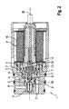
Figur 2- das erfindungsgemäße hydraulische Wegeventil gemäß dem ersten Ausführungsbeispiel mit offener erster Leitung P,
Figur 3- ein erstes
Detail aus Figur 1 , Figur 4- ein zweites
Detail aus Figur 1 , Figur 5- einen Detailausschnitt des erfindungsgemäßen hydraulischen Wegeventils gemäß einem zweiten Ausführungsbeispiel mit geschlossener erster Leitung P, und
Figur 6- ein
Detail aus Figur 5 .
- FIG. 1
- an inventive hydraulic directional control valve according to a first embodiment with closed first line P,
- FIG. 2
- the inventive hydraulic directional control valve according to the first embodiment with open first line P,
- FIG. 3
- a first detail
FIG. 1 . - FIG. 4
- a second detail
FIG. 1 . - FIG. 5
- a detail of the hydraulic directional control valve according to the invention according to a second embodiment with closed first line P, and
- FIG. 6
- a detail from
FIG. 5 ,
Im Folgenden wird anhand der
Das Wegeventil 1 umfasst ein Ventilgehäuse 2 und eine im Ventilgehäuse 2 ausgebildete Ventilkammer 3. Das Ventilgehäuse 2 ist dabei zusammengesetzt aus mehreren ineinander verschraubten und abgedichteten Einsätzen. An dem Ventilgehäuse 2 sind drei Anschlüsse ausgebildet: eine erste Leitung P, eine zweite Leitung A und eine dritte Leitung T. Die erste Leitung P wird auch als Druckleitung bezeichnet. Die zweite Leitung A wird auch als Arbeitsleitung bezeichnet. Die dritte Leitung T führt insbesondere zu einem Tank.The
Des Weiteren umfasst das Wegeventil 1 einen Betätigungsmechanismus, ausgebildet als Elektromagnet, und einen Ventilstößel 5. Der Betätigungsmechanismus 4 dient zum Bewegen des Ventilstößels 5. Der Ventilstößel 5 wird dabei entlang einer Längsachse 20 linearbeweglich verschoben.Furthermore, the
In der Ventilkammer 3 ist eine erste Ventilsitzbohrung 6 als Verbindung zur ersten Leitung P ausgebildet. Des Weiteren ist eine zweite Ventilsitzbohrung 7 als Verbindung zur zweiten Leitung A ausgebildet. Zwischen der ersten Ventilsitzbohrung 6 und der zweiten Ventilsitzbohrung 7 befindet sich eine freie Öffnung 8 in der Ventilkammer 3 als Verbindung zur dritten Leitung T.In the
Der Ventilstößel 5 ist teilweise in der Ventilkammer 3 angeordnet. Zur Erleichterung der Montage ist der Ventilstößel 5 zweiteilig ausgebildet und besteht aus einem ersten Teil 12, der in den Betätigungsmechanismus 4 hineinragt und einen zweiten Teil 13, der durch die zweite Ventilsitzbohrung 7 hindurch in die Ventilkammer 3 hineinragt. Die beiden Teile 12, 13 sind fest miteinander verschraubt. Zum Druckausgleich ist ein Verbindungskanal 15 im Ventilstößel 5 vorgesehen.The
Bestandteil des Ventilstößels 5 ist eine Kugel 10. Die Kugel 10 stellt eine erste Dichtfläche 9, ausgebildet als konvexe Oberfläche, dar. Diese erste Dichtfläche 9 ist der ersten Ventilsitzbohrung 6 zugewandt. Somit ist durch die erste Ventilsitzbohrung 6 und die erste Dichtfläche 9 ein erster Ventilsitz gebildet. Des Weiteren ist am Ventilstößel 5 eine zweite Dichtfläche 11, ausgebildet als Kegelringfläche, angeordnet. Die zweite Dichtfläche 11 bildet zusammen mit der zweiten Ventilsitzbohrung 7 einen zweiten Ventilsitz.Part of the
Der Betätigungsmechanismus 4, ausgebildet als Elektromagnet, umfasst eine Spule 16, die bestromt werden kann und somit den Ventilstößel 5 bewegt. Im bestromten Zustand der Spule 16 ist der Ventilstößel 5 gemäß der Darstellung in
Zur Rückstellung des Ventilstößels 5, also zum Aufdrücken der zweiten Dichtfläche 11 auf die zweite Ventilsitzbohrung 7, ist eine Rückstellfeder 14 in der Ventilkammer 3 angeordnet.To return the
Zwischen der ersten Ventilsitzbohrung 6 und dem Anschluss der ersten Leitung P im Ventilgehäuse 2, befindet sich ein Filter 17.
-
Figur 1Ventilsitzbohrung 6. -
Figur 2Ventilsitzbohrung 6.
-
FIG. 1 shows the closed position of the first valve seat bore. 6 -
FIG. 2 shows the open position of the first valve seat bore. 6
Die
Der vierte Durchmesser 24 entspricht in etwa dem zweiten Durchmesser 22. Dadurch ist bei einem minimalen Abheben der ersten Dichtfläche 9 von der ersten Ventilsitzbohrung 6 annähernd kein Fluidfluss von der Staukammer 18 in die Hauptkammer 19 möglich. Die minimale Differenz zwischen dem zweiten Durchmesser 22 und dem vierten Durchmesser 24 definiert die Strömungsquerschnittsfläche des Fluidflusses von der Staukammer 18 in die Hauptkammer 19. Diese Strömungsquerschnittsfläche ist äußerst klein oder gleich Null. Entscheidend ist, dass diese Strömungsquerschnittsfläche kleiner der durch den ersten Durchmesser 21 definierten Strömungsquerschnittsfläche ist.The
Des Weiteren ist vorgesehen, dass der zweite Durchmesser 22 der Staukammer 18 wesentlich größer als der erste Durchmesser 21 ist, so dass hier eine ausreichend große Fläche zum Betätigen des Ventilstößels 5 zur Verfügung steht. Insbesondere ist der zweite Durchmesser 22 zumindest doppelt so groß wie der erste Durchmesser 21. So entsteht eine ausreichende Rückstellkraft die den Ventilstößel 5 auch gegen Massenträgheit und Reibung schnell und sicher in die zweite Stufe bewegt. Des Weiteren ist der dritte Durchmesser 23 zumindest um 20% größer als der zweite Durchmesser 22, so dass ein ausreichender Durchfluss zwischen der ersten Leitung P und der Tankleitung T möglich ist.Furthermore, it is provided that the
Die
Im zweiten Ausführungsbeispiel wird die Unterteilung der Ventilkammer 3 in die Staukammer 18 und die Hauptkammer 19 durch eine Scheibe 27 als Teil des Ventilstößels 5 bewirkt. Mittels dieser Scheibe 27 ist ein fluiddichtes Abdichten zur Innenwandung der Ventilkammer 3 hin möglich. Wie
Zusammenfassend ist festzustellen, dass die Erfindung einen zusätzlichen Wirkraum (Staukammer 18) in der Ventilkammer 3 vorsieht, mit dem die hohe Flüssigkeitsenergie des vorgespannten Hydraulikmediums von der ersten Leitung P zur Rückstellung des Ventilstößels 5 und des Spulenankers genutzt werden kann.In summary, it should be noted that the invention provides an additional effective space (storage chamber 18) in the
Nach Abschalten des Elektromagneten öffnet sich durch die abfallende Zuhaltekraft des Ventilstößels 5 der Kugelventilsitz 6, 9, wodurch eine kleine Menge des vorgespannten Hydraulikmediums aus der ersten Leitung P, beispielsweise dem Sperrraum eines Türbetätigers, in die Staukammer 18 abströmen kann. Ein weiteres Abströmen in die dritte Leitung T bzw. den Tank, ist aber nicht unmittelbar möglich, sondern das Hydraulikfluid wird zunächst in der Staukammer 18 aufgestaut. In der Staukammer 18 wird das hohe Energiepotential des vorgespannten Fluides über eine im Vergleich zur Fläche der ersten Ventilsitzbohrung 6 deutlich größere Fläche, definiert durch den zweiten Durchmesser 22, auf die Stirnseite des Ventilstößels 5 für die sehr schnelle und sichere Rückstellung des Ventilstößels 5 und des Spulenankers ausgenutzt. Der Ventilstößel 5 wird hier gleichzeitig als Arbeitskolben zur Aufbringung der Stell- bzw. Schaltkräfte genutzt.After switching off the electromagnet opens by the falling clamping force of the
Der freie Abfluss des energiereichen Öls zum druckarmen Tankraum wird erst dann ermöglicht, wenn nach einem definierten Hub (definiert durch die zweite Länge 26) des Ventilstößels 5 der gegensätzliche Ventilsitz 7, 11 geschlossen wurde. Eine zuvor positive Überdeckung (definiert durch die erste Länge 25) des Ventilstößels 5 mit der Ventilkammer 3, ausgestattet mit einem sehr kleinen Ringspaltmaß, wird mit dem Erreichen des zweiten Ventilsitzes 7, 11 freigefahren.The free outflow of the high-energy oil to the low-pressure tank space is only possible if after a defined stroke (defined by the second length 26) of the
Das Maß der positiven Überdeckung, also die erste Länge 25, bis zur Freigabe des Tankablaufs über die dritte Leitung T wird abhängig von der Bewegung des Ventilstößels 5 bis zum Anliegen der zweiten Dichtfläche 11 an der zweiten Ventilsitzbohrung 7 mit Steuerkanten 28 eingestellt. Nach Überfahren der Steuerkanten 28 ist der Fluidfluss von der ersten Leitung P zur dritten Leitung T annähernd frei und das restliche, eingespannte Hydrauliköl aus der ersten Leitung P kann frei in die dritte Leitung T abströmen.The extent of the positive overlap, ie the
Dieser Vorgang findet in Bruchteilen von Sekunden statt und vermeidet undefinierte Schaltzustände bzw. Zwischenpositionen des Wegeventils 1. Durch die hohen Rückstellkräfte, erzeugt in der Staukammer 18, werden auch schwergängige Ventilstößel 5, z.B. bei ungünstigen Toleranzen der Bauteile zueinander, sicher und ohne Verzögerung in die jeweilige andere Schaltstellung gebracht. Zudem können Dichtungsreibungen ausgeglichen werden. Die Massenträgheit des relativ schweren Magnetankers, wird durch das hohe Kraftpotential souverän überwunden.This process takes place in fractions of a second and avoids undefined switching states or intermediate positions of the
Statt der Ausführung mit der positiven Überdeckung gemäß dem ersten Ausführungsbeispiel kann gemäß dem zweiten Ausführungsbeispiel die Scheibe 27 eingesetzt werden. Der Flüssigkeitsdruck in der Staukammer 18 trifft dabei auf eine Art Prallplatte (Scheibe 26), die erst nach erfolgtem Ventilstößelhub die Abflussbohrung zur dritten Leitung T freifährt. Im zweiten Ausführungsbeispiel kann aufgrund der Scheibe 26 von einem "dichten" System gesprochen werden. Im ersten Ausführungsbeispiel wird eine Leckage zwischen dem zweiten Durchmesser 22 und dem vierten Durchmesser 24 toleriert.Instead of the embodiment with the positive overlap according to the first embodiment, the
Das beschriebene Wegeventil 1 ist insbesondere bei einem Türschließermechanismus mit Speicherfeder anwendbar. Nach einmaligem Vorspannen von Hand über den Türflügel, durch eine interne Motor-Pumpeneinheit, oder durch ein elektromechanisch wirkendes Getriebe, wird die Speicherfeder über den Sperrraum hydraulisch gespannt gehalten. Nach der Abschaltung der Halteeinrichtung kann die gespeicherte Energie aus der Speicherfeder für eine sichere Schließung der Tür im Not- oder Bedarfsfall genutzt werden.The
Der gezeigte Aufbau des beschriebenen Wegeventils 1 kann aber auch in vielen anderen Bereichen eingesetzt werden. Insbesondere überall dort, wo hydraulisch wirkende Wegeventile mit geringen Betätigungskräften trotzdem schnell und sicher geschaltet werden müssen, kann die Anwendung der gezeigten Erfindung vorteilhaft und sinnvoll sein.The construction shown the described
- 11
- Hydraulikwegeventil, insbesondere 3/2-MagnetwegeventilHydraulic directional valve, in particular 3/2 solenoid valve
- 22
- Ventilgehäusevalve housing
- 33
- Ventilkammervalve chamber
- 44
- Betätigungsmechanismus, insbesondere ElektromagnetActuating mechanism, in particular electromagnet
- 55
- Ventilstößeltappet
- 66
- erste Ventilsitzbohrungfirst valve seat bore
- 77
- zweite Ventilsitzbohrungsecond valve seat bore
- 88th
- freie Öffnungfree opening
- 99
- erste Dichtfläche, insbesondere konvexe Oberflächefirst sealing surface, in particular convex surface
- 1010
- KugelBullet
- 1111
- zweite Dichtfläche, insbesondere Kegelringflächesecond sealing surface, in particular conical ring surface
- 1212
- erster Teilfirst part
- 1313
- zweiter Teilsecond part
- 1414
- RückstellfederReturn spring
- 1515
- Verbindungskanalconnecting channel
- 1616
- SpuleKitchen sink
- 1717
- Filterfilter
- 1818
- Staukammerstorage chamber
- 1919
- Hauptkammermain chamber
- 2020
- Längsachselongitudinal axis
- 21, 22, 23, 2421, 22, 23, 24
- Durchmesserdiameter
- 25,2625.26
- Längenlengths
- 2727
- Scheibe, insbesondere DichtscheibeDisc, in particular sealing disc
- 2828
- Steuerkantencontrol edges
Claims (12)
- A hydraulic distribution valve (1), comprising:- a valve housing (2),- a valve chamber (3) integrated into the valve housing (2) and having at least one first valve seat bore (6) as a connection to a first line (P), a second valve seat bore (7) as a connection to a second line (A), and a free aperture (8) to a third line (T),- an actuating mechanism (4), and- a valve spindle (5) which is moveable by means of the actuating mechanism (4) and is partly disposed in the valve chamber (3),- wherein the valve spindle (5) within the valve chamber (3) comprises a surface, preferably a convex surface as a first sealing surface (9), oriented towards the first valve seat bore (6), and a surface, preferably a cone-shaped surface as a second sealing surface (11), oriented towards the second valve seat bore (7), in such a way that optionally the first valve seat bore (6) or the second valve seat bore (7) can be closed, characterized in that- by configuring an external contour of the valve spindle (5) and an internal contour of the valve chamber (3), the valve chamber (3) is subdivided into a retaining chamber (18) and a main chamber (19),- wherein the retaining chamber (18) is formed between the first valve seat bore (6) and the valve spindle (5), and- wherein the first flow cross-sectional surface in the first valve seat bore (6) is larger than another flow cross-sectional surface of the flow from the retaining chamber (18) into the main chamber (19) or into the third line (T) at a minimum lifting of the first sealing surface (9) off the first valve seat bore (6).
- The hydraulic distribution valve according to any of the preceding claims, characterized in that the retaining chamber (18) is formed by means of a shoulder at the external contour of the valve spindle (5) and/or a shoulder at the internal contour of the valve chamber (3).
- The hydraulic distribution valve according to any of the preceding claims, characterized in that the further flow cross-sectional surface is a ring surface.
- The hydraulic distribution valve according to any of the preceding claims, characterized in that, at a minimum lifting of the first sealing surface (9) off the first valve seat bore (6), the further flow cross-sectional surface is smaller than at a further travel movement of the first sealing surface (9) off the first valve seat bore (6).
- The hydraulic distribution valve according to any of the preceding claims, characterized in that the valve spindle (5) comprises a disc (27) which for forming the retaining chamber (18) on the entire circumference, preferably in a fluid-tight manner, bears against the internal contour of the valve chamber (3).
- The hydraulic distribution valve according to claim 5, characterized in that the disc (27) comprises a sealing joint or in that the disc (27) is configured as a sealing joint.
- The hydraulic distribution valve according to any of the preceding claims, characterized by a return spring (14) for moving the valve spindle (5) in the closing direction of the second valve seat bore (7), wherein the actuating mechanism (4) is configured just for moving the valve spindle (5) in the closing direction of the first valve seat bore (6).
- The hydraulic distribution valve according to any of the preceding claims, characterized in that the valve spindle (5) extends from the valve chamber (3) through the second valve seat bore (7) towards the actuating mechanism (4).
- The hydraulic distribution valve according to any of the preceding claims, characterized in that the first sealing surface (9) is configured by means of a sphere (10).
- The hydraulic distribution valve according to any of the preceding claims, characterized in that the second sealing surface (11) is configured as a cone ring surface.
- The hydraulic distribution valve according to any of the preceding claims, characterized in that a frontal face of the valve spindle, on which the fluid impacts after the minimum lifting of the first sealing surface (9) off the first valve seat bore (6), is considerably larger than a cross-sectional surface of the first valve seat bore (6) at the exit of the retaining chamber.
- A door operator for moving a door leaf, comprising- a housing,- a drive unit with an output shaft disposed in the housing,- an accumulating spring for storing closing energy or opening energy for the door leaf,- a hydraulic blocking space, formed inside the housing, for blocking the contracting accumulating spring,- a hydraulic dampening space, formed inside the housing, for dampening the movement of the drive unit, and- a hydraulic distribution valve (1) according to any of the preceding claims, wherein the first line (P) is connected to the blocking space and the second line (A) is connected to the dampening space.
Applications Claiming Priority (1)
| Application Number | Priority Date | Filing Date | Title |
|---|---|---|---|
| DE201210106684 DE102012106684A1 (en) | 2012-07-24 | 2012-07-24 | Hydraulic directional valve |
Publications (3)
| Publication Number | Publication Date |
|---|---|
| EP2690327A2 EP2690327A2 (en) | 2014-01-29 |
| EP2690327A3 EP2690327A3 (en) | 2014-05-14 |
| EP2690327B1 true EP2690327B1 (en) | 2015-09-16 |
Family
ID=48470693
Family Applications (1)
| Application Number | Title | Priority Date | Filing Date |
|---|---|---|---|
| EP13002664.4A Active EP2690327B1 (en) | 2012-07-24 | 2013-05-22 | Hydraulic directional valve |
Country Status (2)
| Country | Link |
|---|---|
| EP (1) | EP2690327B1 (en) |
| DE (1) | DE102012106684A1 (en) |
Families Citing this family (4)
| Publication number | Priority date | Publication date | Assignee | Title |
|---|---|---|---|---|
| EP3034890B1 (en) * | 2014-12-17 | 2019-06-12 | dormakaba Deutschland GmbH | Hydraulic valve and drive control unit, comprising such a hydraulic valve |
| DE102016011058B4 (en) | 2016-09-12 | 2018-03-29 | Thomas Magnete Gmbh | Seat valve with electromagnetic actuation |
| DE102016011059A1 (en) | 2016-09-12 | 2018-03-15 | Thomas Magnete Gmbh | Seat valve with electromagnetic actuation |
| CN107762996B (en) * | 2017-10-31 | 2024-04-16 | 中国第一汽车股份有限公司 | Hydraulic control valve block for automatic transmission |
Family Cites Families (3)
| Publication number | Priority date | Publication date | Assignee | Title |
|---|---|---|---|---|
| US3926218A (en) * | 1974-09-13 | 1975-12-16 | Cillichemie | Valve |
| US6966338B2 (en) * | 2004-01-08 | 2005-11-22 | Husco International, Inc. | Electrohydraulic valve for controlling operation of an engine cylinder valve |
| BR112012025096A2 (en) * | 2010-04-01 | 2017-09-12 | Dorma Gmbh & Co Kg | HYDRAULIC CONTROL SOLENOID VALVE |
-
2012
- 2012-07-24 DE DE201210106684 patent/DE102012106684A1/en not_active Withdrawn
-
2013
- 2013-05-22 EP EP13002664.4A patent/EP2690327B1/en active Active
Also Published As
| Publication number | Publication date |
|---|---|
| EP2690327A2 (en) | 2014-01-29 |
| EP2690327A3 (en) | 2014-05-14 |
| DE102012106684A1 (en) | 2014-01-30 |
Similar Documents
| Publication | Publication Date | Title |
|---|---|---|
| WO2010085991A2 (en) | Proportional pressure control valve | |
| EP2494242B1 (en) | Solenoid valve | |
| DE4212550C2 (en) | Valve arrangement with a directional valve | |
| DE102013106214A1 (en) | Piston valve | |
| DE102018107763A1 (en) | MAGNETIC VALVE | |
| EP2558757B1 (en) | Flow control valve | |
| EP1771675B1 (en) | Electrically controllable valve | |
| DE102014216580A1 (en) | Hydraulic control device for an automatic transmission | |
| EP2690327B1 (en) | Hydraulic directional valve | |
| DE10143959A1 (en) | Hydraulically controled actuator for valve, especially gas replacement valve in combustion engine, has control piston with area of working surface(s) changing along piston displacement path | |
| EP2519732B1 (en) | Electromagnetically actuated metering control valve, particularly for controlling the flow of a high pressure fuel pump | |
| DE4032078C2 (en) | Control device for a hydraulic working cylinder | |
| DE102014226623A1 (en) | Pressure relief valve and thus equipped hydraulic machine | |
| DE102011002600A1 (en) | Valve arrangement e.g. solenoid valve arrangement, for hydraulic actuation of e.g. wet clutch unit of automatic gearbox of motor car, has pressure regulating valve controlling operating pressure of slide valve that includes valve spool | |
| DE102007017814A1 (en) | Valve | |
| EP3295026A1 (en) | Solenoid pump for an auxiliary unit of a vehicle | |
| DE102006036615B4 (en) | Controllable solenoid valve | |
| DE102004048071A1 (en) | Valve drive for a cam-operated lift valve | |
| DE102013113673A1 (en) | Electromagnetic pressure control valve | |
| DE102005020419A1 (en) | Double safety valve has two coaxial closing components mounted, together with magnet, on common valve stem, closing component nearer outlet and magnet being coupled to movement of stem and closing component acting as double-seat valve | |
| DE3822830A1 (en) | Valve for liquid media operated by its own medium and servo-controlled by a bistable solenoid valve | |
| EP3359851A1 (en) | Electromagnetic switch valve | |
| EP1573212B1 (en) | Electromagnet | |
| DE102016205041A1 (en) | spool valve | |
| EP3686465A1 (en) | Quick switch valve |
Legal Events
| Date | Code | Title | Description |
|---|---|---|---|
| PUAI | Public reference made under article 153(3) epc to a published international application that has entered the european phase |
Free format text: ORIGINAL CODE: 0009012 |
|
| AK | Designated contracting states |
Kind code of ref document: A2 Designated state(s): AL AT BE BG CH CY CZ DE DK EE ES FI FR GB GR HR HU IE IS IT LI LT LU LV MC MK MT NL NO PL PT RO RS SE SI SK SM TR |
|
| AX | Request for extension of the european patent |
Extension state: BA ME |
|
| PUAL | Search report despatched |
Free format text: ORIGINAL CODE: 0009013 |
|
| AK | Designated contracting states |
Kind code of ref document: A3 Designated state(s): AL AT BE BG CH CY CZ DE DK EE ES FI FR GB GR HR HU IE IS IT LI LT LU LV MC MK MT NL NO PL PT RO RS SE SI SK SM TR |
|
| AX | Request for extension of the european patent |
Extension state: BA ME |
|
| RIC1 | Information provided on ipc code assigned before grant |
Ipc: E05F 3/22 20060101ALI20140408BHEP Ipc: F16K 11/044 20060101AFI20140408BHEP |
|
| 17P | Request for examination filed |
Effective date: 20141114 |
|
| RBV | Designated contracting states (corrected) |
Designated state(s): AL AT BE BG CH CY CZ DE DK EE ES FI FR GB GR HR HU IE IS IT LI LT LU LV MC MK MT NL NO PL PT RO RS SE SI SK SM TR |
|
| GRAP | Despatch of communication of intention to grant a patent |
Free format text: ORIGINAL CODE: EPIDOSNIGR1 |
|
| RAP1 | Party data changed (applicant data changed or rights of an application transferred) |
Owner name: DORMA DEUTSCHLAND GMBH |
|
| INTG | Intention to grant announced |
Effective date: 20150330 |
|
| GRAS | Grant fee paid |
Free format text: ORIGINAL CODE: EPIDOSNIGR3 |
|
| GRAA | (expected) grant |
Free format text: ORIGINAL CODE: 0009210 |
|
| AK | Designated contracting states |
Kind code of ref document: B1 Designated state(s): AL AT BE BG CH CY CZ DE DK EE ES FI FR GB GR HR HU IE IS IT LI LT LU LV MC MK MT NL NO PL PT RO RS SE SI SK SM TR |
|
| REG | Reference to a national code |
Ref country code: GB Ref legal event code: FG4D Free format text: NOT ENGLISH |
|
| REG | Reference to a national code |
Ref country code: CH Ref legal event code: EP Ref country code: CH Ref legal event code: NV Representative=s name: ISLER AND PEDRAZZINI AG, CH |
|
| REG | Reference to a national code |
Ref country code: IE Ref legal event code: FG4D Free format text: LANGUAGE OF EP DOCUMENT: GERMAN |
|
| REG | Reference to a national code |
Ref country code: AT Ref legal event code: REF Ref document number: 750093 Country of ref document: AT Kind code of ref document: T Effective date: 20151015 |
|
| REG | Reference to a national code |
Ref country code: DE Ref legal event code: R096 Ref document number: 502013001154 Country of ref document: DE |
|
| REG | Reference to a national code |
Ref country code: NL Ref legal event code: FP |
|
| PG25 | Lapsed in a contracting state [announced via postgrant information from national office to epo] |
Ref country code: GR Free format text: LAPSE BECAUSE OF FAILURE TO SUBMIT A TRANSLATION OF THE DESCRIPTION OR TO PAY THE FEE WITHIN THE PRESCRIBED TIME-LIMIT Effective date: 20151217 Ref country code: NO Free format text: LAPSE BECAUSE OF FAILURE TO SUBMIT A TRANSLATION OF THE DESCRIPTION OR TO PAY THE FEE WITHIN THE PRESCRIBED TIME-LIMIT Effective date: 20151216 Ref country code: LV Free format text: LAPSE BECAUSE OF FAILURE TO SUBMIT A TRANSLATION OF THE DESCRIPTION OR TO PAY THE FEE WITHIN THE PRESCRIBED TIME-LIMIT Effective date: 20150916 Ref country code: LT Free format text: LAPSE BECAUSE OF FAILURE TO SUBMIT A TRANSLATION OF THE DESCRIPTION OR TO PAY THE FEE WITHIN THE PRESCRIBED TIME-LIMIT Effective date: 20150916 |
|
| REG | Reference to a national code |
Ref country code: LT Ref legal event code: MG4D |
|
| PG25 | Lapsed in a contracting state [announced via postgrant information from national office to epo] |
Ref country code: RS Free format text: LAPSE BECAUSE OF FAILURE TO SUBMIT A TRANSLATION OF THE DESCRIPTION OR TO PAY THE FEE WITHIN THE PRESCRIBED TIME-LIMIT Effective date: 20150916 Ref country code: SE Free format text: LAPSE BECAUSE OF FAILURE TO SUBMIT A TRANSLATION OF THE DESCRIPTION OR TO PAY THE FEE WITHIN THE PRESCRIBED TIME-LIMIT Effective date: 20150916 Ref country code: HR Free format text: LAPSE BECAUSE OF FAILURE TO SUBMIT A TRANSLATION OF THE DESCRIPTION OR TO PAY THE FEE WITHIN THE PRESCRIBED TIME-LIMIT Effective date: 20150916 |
|
| PG25 | Lapsed in a contracting state [announced via postgrant information from national office to epo] |
Ref country code: CZ Free format text: LAPSE BECAUSE OF FAILURE TO SUBMIT A TRANSLATION OF THE DESCRIPTION OR TO PAY THE FEE WITHIN THE PRESCRIBED TIME-LIMIT Effective date: 20150916 Ref country code: ES Free format text: LAPSE BECAUSE OF FAILURE TO SUBMIT A TRANSLATION OF THE DESCRIPTION OR TO PAY THE FEE WITHIN THE PRESCRIBED TIME-LIMIT Effective date: 20150916 Ref country code: SK Free format text: LAPSE BECAUSE OF FAILURE TO SUBMIT A TRANSLATION OF THE DESCRIPTION OR TO PAY THE FEE WITHIN THE PRESCRIBED TIME-LIMIT Effective date: 20150916 Ref country code: IS Free format text: LAPSE BECAUSE OF FAILURE TO SUBMIT A TRANSLATION OF THE DESCRIPTION OR TO PAY THE FEE WITHIN THE PRESCRIBED TIME-LIMIT Effective date: 20160116 Ref country code: EE Free format text: LAPSE BECAUSE OF FAILURE TO SUBMIT A TRANSLATION OF THE DESCRIPTION OR TO PAY THE FEE WITHIN THE PRESCRIBED TIME-LIMIT Effective date: 20150916 |
|
| PG25 | Lapsed in a contracting state [announced via postgrant information from national office to epo] |
Ref country code: RO Free format text: LAPSE BECAUSE OF FAILURE TO SUBMIT A TRANSLATION OF THE DESCRIPTION OR TO PAY THE FEE WITHIN THE PRESCRIBED TIME-LIMIT Effective date: 20150916 Ref country code: PT Free format text: LAPSE BECAUSE OF FAILURE TO SUBMIT A TRANSLATION OF THE DESCRIPTION OR TO PAY THE FEE WITHIN THE PRESCRIBED TIME-LIMIT Effective date: 20160118 Ref country code: PL Free format text: LAPSE BECAUSE OF FAILURE TO SUBMIT A TRANSLATION OF THE DESCRIPTION OR TO PAY THE FEE WITHIN THE PRESCRIBED TIME-LIMIT Effective date: 20150916 |
|
| REG | Reference to a national code |
Ref country code: CH Ref legal event code: NV Representative=s name: RENTSCH PARTNER AG, CH |
|
| REG | Reference to a national code |
Ref country code: DE Ref legal event code: R097 Ref document number: 502013001154 Country of ref document: DE |
|
| PLBE | No opposition filed within time limit |
Free format text: ORIGINAL CODE: 0009261 |
|
| STAA | Information on the status of an ep patent application or granted ep patent |
Free format text: STATUS: NO OPPOSITION FILED WITHIN TIME LIMIT |
|
| 26N | No opposition filed |
Effective date: 20160617 |
|
| PG25 | Lapsed in a contracting state [announced via postgrant information from national office to epo] |
Ref country code: DK Free format text: LAPSE BECAUSE OF FAILURE TO SUBMIT A TRANSLATION OF THE DESCRIPTION OR TO PAY THE FEE WITHIN THE PRESCRIBED TIME-LIMIT Effective date: 20150916 Ref country code: BE Free format text: LAPSE BECAUSE OF NON-PAYMENT OF DUE FEES Effective date: 20160531 |
|
| PG25 | Lapsed in a contracting state [announced via postgrant information from national office to epo] |
Ref country code: SI Free format text: LAPSE BECAUSE OF FAILURE TO SUBMIT A TRANSLATION OF THE DESCRIPTION OR TO PAY THE FEE WITHIN THE PRESCRIBED TIME-LIMIT Effective date: 20150916 |
|
| PG25 | Lapsed in a contracting state [announced via postgrant information from national office to epo] |
Ref country code: LU Free format text: LAPSE BECAUSE OF FAILURE TO SUBMIT A TRANSLATION OF THE DESCRIPTION OR TO PAY THE FEE WITHIN THE PRESCRIBED TIME-LIMIT Effective date: 20160522 |
|
| REG | Reference to a national code |
Ref country code: IE Ref legal event code: MM4A |
|
| REG | Reference to a national code |
Ref country code: FR Ref legal event code: ST Effective date: 20170131 |
|
| REG | Reference to a national code |
Ref country code: CH Ref legal event code: PFA Owner name: DORMAKABA DEUTSCHLAND GMBH, DE Free format text: FORMER OWNER: DORMA DEUTSCHLAND GMBH, DE |
|
| PG25 | Lapsed in a contracting state [announced via postgrant information from national office to epo] |
Ref country code: FR Free format text: LAPSE BECAUSE OF NON-PAYMENT OF DUE FEES Effective date: 20160531 |
|
| REG | Reference to a national code |
Ref country code: DE Ref legal event code: R082 Ref document number: 502013001154 Country of ref document: DE Representative=s name: BALDER IP LAW, S.L., ES Ref country code: DE Ref legal event code: R081 Ref document number: 502013001154 Country of ref document: DE Owner name: DORMAKABA DEUTSCHLAND GMBH, DE Free format text: FORMER OWNER: DORMA DEUTSCHLAND GMBH, 58256 ENNEPETAL, DE |
|
| PG25 | Lapsed in a contracting state [announced via postgrant information from national office to epo] |
Ref country code: IE Free format text: LAPSE BECAUSE OF NON-PAYMENT OF DUE FEES Effective date: 20160522 |
|
| REG | Reference to a national code |
Ref country code: NL Ref legal event code: HC Owner name: DORMAKABA DEUTSCHLAND GMBH; DE Free format text: DETAILS ASSIGNMENT: CHANGE OF OWNER(S), CHANGE OF OWNER(S) NAME; FORMER OWNER NAME: DORMA DEUTSCHLAND GMBH Effective date: 20170707 |
|
| REG | Reference to a national code |
Ref country code: CH Ref legal event code: PCAR Free format text: NEW ADDRESS: BELLERIVESTRASSE 203 POSTFACH, 8034 ZUERICH (CH) |
|
| GBPC | Gb: european patent ceased through non-payment of renewal fee |
Effective date: 20170522 |
|
| PG25 | Lapsed in a contracting state [announced via postgrant information from national office to epo] |
Ref country code: GB Free format text: LAPSE BECAUSE OF NON-PAYMENT OF DUE FEES Effective date: 20170522 |
|
| PG25 | Lapsed in a contracting state [announced via postgrant information from national office to epo] |
Ref country code: HU Free format text: LAPSE BECAUSE OF FAILURE TO SUBMIT A TRANSLATION OF THE DESCRIPTION OR TO PAY THE FEE WITHIN THE PRESCRIBED TIME-LIMIT; INVALID AB INITIO Effective date: 20130522 Ref country code: CY Free format text: LAPSE BECAUSE OF FAILURE TO SUBMIT A TRANSLATION OF THE DESCRIPTION OR TO PAY THE FEE WITHIN THE PRESCRIBED TIME-LIMIT Effective date: 20150916 Ref country code: SM Free format text: LAPSE BECAUSE OF FAILURE TO SUBMIT A TRANSLATION OF THE DESCRIPTION OR TO PAY THE FEE WITHIN THE PRESCRIBED TIME-LIMIT Effective date: 20150916 |
|
| PG25 | Lapsed in a contracting state [announced via postgrant information from national office to epo] |
Ref country code: MK Free format text: LAPSE BECAUSE OF FAILURE TO SUBMIT A TRANSLATION OF THE DESCRIPTION OR TO PAY THE FEE WITHIN THE PRESCRIBED TIME-LIMIT Effective date: 20150916 Ref country code: TR Free format text: LAPSE BECAUSE OF FAILURE TO SUBMIT A TRANSLATION OF THE DESCRIPTION OR TO PAY THE FEE WITHIN THE PRESCRIBED TIME-LIMIT Effective date: 20150916 Ref country code: MC Free format text: LAPSE BECAUSE OF FAILURE TO SUBMIT A TRANSLATION OF THE DESCRIPTION OR TO PAY THE FEE WITHIN THE PRESCRIBED TIME-LIMIT Effective date: 20150916 Ref country code: MT Free format text: LAPSE BECAUSE OF FAILURE TO SUBMIT A TRANSLATION OF THE DESCRIPTION OR TO PAY THE FEE WITHIN THE PRESCRIBED TIME-LIMIT Effective date: 20150916 |
|
| PG25 | Lapsed in a contracting state [announced via postgrant information from national office to epo] |
Ref country code: BG Free format text: LAPSE BECAUSE OF FAILURE TO SUBMIT A TRANSLATION OF THE DESCRIPTION OR TO PAY THE FEE WITHIN THE PRESCRIBED TIME-LIMIT Effective date: 20150916 |
|
| PG25 | Lapsed in a contracting state [announced via postgrant information from national office to epo] |
Ref country code: AL Free format text: LAPSE BECAUSE OF FAILURE TO SUBMIT A TRANSLATION OF THE DESCRIPTION OR TO PAY THE FEE WITHIN THE PRESCRIBED TIME-LIMIT Effective date: 20150916 |
|
| REG | Reference to a national code |
Ref country code: AT Ref legal event code: MM01 Ref document number: 750093 Country of ref document: AT Kind code of ref document: T Effective date: 20180522 |
|
| PG25 | Lapsed in a contracting state [announced via postgrant information from national office to epo] |
Ref country code: AT Free format text: LAPSE BECAUSE OF NON-PAYMENT OF DUE FEES Effective date: 20180522 |
|
| PGFP | Annual fee paid to national office [announced via postgrant information from national office to epo] |
Ref country code: NL Payment date: 20230519 Year of fee payment: 11 Ref country code: IT Payment date: 20230526 Year of fee payment: 11 Ref country code: DE Payment date: 20220620 Year of fee payment: 11 Ref country code: CH Payment date: 20230602 Year of fee payment: 11 |
|
| PGFP | Annual fee paid to national office [announced via postgrant information from national office to epo] |
Ref country code: FI Payment date: 20230523 Year of fee payment: 11 |