EP2690303A1 - Träger und Montiereinheit - Google Patents
Träger und Montiereinheit Download PDFInfo
- Publication number
- EP2690303A1 EP2690303A1 EP13177534.8A EP13177534A EP2690303A1 EP 2690303 A1 EP2690303 A1 EP 2690303A1 EP 13177534 A EP13177534 A EP 13177534A EP 2690303 A1 EP2690303 A1 EP 2690303A1
- Authority
- EP
- European Patent Office
- Prior art keywords
- carrier
- mount
- location
- holes
- locator
- Prior art date
- Legal status (The legal status is an assumption and is not a legal conclusion. Google has not performed a legal analysis and makes no representation as to the accuracy of the status listed.)
- Granted
Links
- 230000015572 biosynthetic process Effects 0.000 claims abstract description 144
- 238000005755 formation reaction Methods 0.000 claims abstract description 144
- 238000003780 insertion Methods 0.000 claims abstract description 16
- 230000037431 insertion Effects 0.000 claims abstract description 16
- 238000000034 method Methods 0.000 claims description 28
- 229910000639 Spring steel Inorganic materials 0.000 claims description 3
- 230000001419 dependent effect Effects 0.000 claims 1
- 238000003466 welding Methods 0.000 description 4
- 239000000969 carrier Substances 0.000 description 2
- 238000003801 milling Methods 0.000 description 2
- 230000000712 assembly Effects 0.000 description 1
- 238000000429 assembly Methods 0.000 description 1
- 230000006835 compression Effects 0.000 description 1
- 238000007906 compression Methods 0.000 description 1
- 230000000694 effects Effects 0.000 description 1
- 230000002401 inhibitory effect Effects 0.000 description 1
- 238000003754 machining Methods 0.000 description 1
- 239000000463 material Substances 0.000 description 1
- 238000012986 modification Methods 0.000 description 1
- 230000004048 modification Effects 0.000 description 1
Images


Classifications
-
- F—MECHANICAL ENGINEERING; LIGHTING; HEATING; WEAPONS; BLASTING
- F16—ENGINEERING ELEMENTS AND UNITS; GENERAL MEASURES FOR PRODUCING AND MAINTAINING EFFECTIVE FUNCTIONING OF MACHINES OR INSTALLATIONS; THERMAL INSULATION IN GENERAL
- F16D—COUPLINGS FOR TRANSMITTING ROTATION; CLUTCHES; BRAKES
- F16D65/00—Parts or details
- F16D65/005—Components of axially engaging brakes not otherwise provided for
- F16D65/0056—Brake supports
-
- F—MECHANICAL ENGINEERING; LIGHTING; HEATING; WEAPONS; BLASTING
- F16—ENGINEERING ELEMENTS AND UNITS; GENERAL MEASURES FOR PRODUCING AND MAINTAINING EFFECTIVE FUNCTIONING OF MACHINES OR INSTALLATIONS; THERMAL INSULATION IN GENERAL
- F16D—COUPLINGS FOR TRANSMITTING ROTATION; CLUTCHES; BRAKES
- F16D55/00—Brakes with substantially-radial braking surfaces pressed together in axial direction, e.g. disc brakes
- F16D55/02—Brakes with substantially-radial braking surfaces pressed together in axial direction, e.g. disc brakes with axially-movable discs or pads pressed against axially-located rotating members
- F16D55/22—Brakes with substantially-radial braking surfaces pressed together in axial direction, e.g. disc brakes with axially-movable discs or pads pressed against axially-located rotating members by clamping an axially-located rotating disc between movable braking members, e.g. movable brake discs or brake pads
-
- F—MECHANICAL ENGINEERING; LIGHTING; HEATING; WEAPONS; BLASTING
- F16—ENGINEERING ELEMENTS AND UNITS; GENERAL MEASURES FOR PRODUCING AND MAINTAINING EFFECTIVE FUNCTIONING OF MACHINES OR INSTALLATIONS; THERMAL INSULATION IN GENERAL
- F16D—COUPLINGS FOR TRANSMITTING ROTATION; CLUTCHES; BRAKES
- F16D65/00—Parts or details
- F16D65/02—Braking members; Mounting thereof
- F16D65/04—Bands, shoes or pads; Pivots or supporting members therefor
- F16D65/092—Bands, shoes or pads; Pivots or supporting members therefor for axially-engaging brakes, e.g. disc brakes
- F16D65/095—Pivots or supporting members therefor
-
- F—MECHANICAL ENGINEERING; LIGHTING; HEATING; WEAPONS; BLASTING
- F16—ENGINEERING ELEMENTS AND UNITS; GENERAL MEASURES FOR PRODUCING AND MAINTAINING EFFECTIVE FUNCTIONING OF MACHINES OR INSTALLATIONS; THERMAL INSULATION IN GENERAL
- F16D—COUPLINGS FOR TRANSMITTING ROTATION; CLUTCHES; BRAKES
- F16D55/00—Brakes with substantially-radial braking surfaces pressed together in axial direction, e.g. disc brakes
- F16D2055/0004—Parts or details of disc brakes
- F16D2055/0008—Brake supports
-
- F—MECHANICAL ENGINEERING; LIGHTING; HEATING; WEAPONS; BLASTING
- F16—ENGINEERING ELEMENTS AND UNITS; GENERAL MEASURES FOR PRODUCING AND MAINTAINING EFFECTIVE FUNCTIONING OF MACHINES OR INSTALLATIONS; THERMAL INSULATION IN GENERAL
- F16D—COUPLINGS FOR TRANSMITTING ROTATION; CLUTCHES; BRAKES
- F16D2250/00—Manufacturing; Assembly
- F16D2250/0084—Assembly or disassembly
-
- Y—GENERAL TAGGING OF NEW TECHNOLOGICAL DEVELOPMENTS; GENERAL TAGGING OF CROSS-SECTIONAL TECHNOLOGIES SPANNING OVER SEVERAL SECTIONS OF THE IPC; TECHNICAL SUBJECTS COVERED BY FORMER USPC CROSS-REFERENCE ART COLLECTIONS [XRACs] AND DIGESTS
- Y10—TECHNICAL SUBJECTS COVERED BY FORMER USPC
- Y10T—TECHNICAL SUBJECTS COVERED BY FORMER US CLASSIFICATION
- Y10T29/00—Metal working
- Y10T29/49—Method of mechanical manufacture
- Y10T29/49826—Assembling or joining
- Y10T29/49947—Assembling or joining by applying separate fastener
Definitions
- the present invention relates to a method of mounting a carrier of a disc brake to a mount, and/or a carrier and mount assembly.
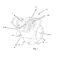
- Disc brakes for example air actuated disc brakes are commonly used for braking heavy vehicles such as trucks, buses and coaches. There are many types of disc brakes available. An example of one of the many types of pneumatic disc brakes is shown in Figure 1 .
- the disc brake 110 has a carrier 112 that carries a caliper 114.
- the carrier also carries friction elements 122 such that one friction element is positioned on each side of a rotor 116 of the disc brake 110.
- An air actuator is provided for moving an inboard friction element into frictional contact with the rotor 116 via an actuator mechanism (not shown).
- the rotor 116 is fixed in an inboard-outboard direction, so that when the inboard friction element is pushed towards and contacts the rotor 116, further pushing of the inboard friction element towards the rotor 116 causes the caliper 114 to move inboard.
- the disc brake is mounted to an axle of a vehicle. This may be achieved by connecting the carrier to a mount on the axle, typically via a bracket welded to the axle. Bolts arranged parallel to an axis of rotation of the rotor secure the carrier to the mount.
- the carrier is generally attached to a separate mount, often referred to as an adapter plate, and the separate mount is connected to the flange.
- Axial mounting may result in difficulty in accessing bolts to assemble/disassemble the brake, as well as increase the weight of the brake due to the material doubling at the interface between the mount and carrier.
- tangential mounting may be used, i.e. the carrier is mounted to the mount via fasteners (e.g. bolts) that extend in a direction tangential to the rotor and substantially perpendicular to the axis of rotation of the rotor.
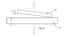
- the carrier and mount generally enable the carrier to be accurately mounted to the axle in a direction A parallel to an axis of rotation of the rotor 116.
- misalignment of the carrier can result in the rotor 116 and friction element 122 being misaligned, such that the friction element 122 is spaced from the rotor by a greater distance 121 at one side of the friction element than at an opposite side of the friction element.
- This misalignment can result in taper (i.e. uneven) pad wear and/or non-uniform loading of the caliper mechanism and components.
- the present invention seeks to alleviate problems associated with the prior art.
- a carrier and mount assembly for a heavy vehicle disc brake, the assembly comprising: a carrier having a first location formation formed therein, a mount having a second location formation formed therein, wherein the second location formation is aligned with the first location formation, and wherein the carrier is mounted to the mount via two or more fasteners that extend in a direction substantially parallel to a direction of insertion or removal of a friction element into or from the carrier; and a locator positioned in the first and second location formations to enable the carrier and mount to be assembled in the correct position, wherein the locator is at least a close fit to the first and second location formations.
- the mounting assembly of the first aspect has been found to ease alignment of the carrier to the mount so as to ensure correct alignment of the carrier to the rotor.
- a close fit may be a transitional fit or an interference fit.
- the fit may have a clearance of between 0 mm to 0.1 mm.
- the size of the clearance will depend on the diameter of the locator.
- the carrier may be seated on the mount such that planar contacting surfaces of the carrier and mount extend in a plane substantially perpendicular to a plane of a rotor and parallel to an axis of rotation of a rotor of a disc brake.
- the first location formation and the second location formation may be positioned to extend in a direction substantially parallel to a direction of insertion or removal of a friction element into or from the carrier.
- the carrier and mount assembly may comprise a location hole formed in the carrier and a location hole formed in the mount.
- the location hole in the carrier and the location hole in the mount may have similar dimensions to the first and second location formation.
- the location hole may be on an opposite side to the first and second location formations of a plane defined by an axis extending substantially parallel to a direction of insertion or removal of a friction element into or from the carrier, and an axis of rotation of a rotor of a disc brake.
- the locator may be a bush.
- the bush may extend at least partially through the first and second location formations.
- the bush may be a split bush. Use of a split bush eases assembly.
- An end of the bush that may be received in the mount may have a chamfered outer edge. Provision of a chamfered edge also eases assembly.
- the bush is may be made from spring steel.
- the carrier may comprise two holes arranged such that one hole is positioned on either side of a plane defined by an axis extending substantially parallel to a direction of insertion or removal of a friction element into or from the carrier, and an axis of rotation of a rotor of a disc brake.
- the mount may comprise two holes positioned to be substantially coaxial with the two holes of the carrier.
- One of the two or more fasteners may extend through each of the holes for mounting the carrier to the mount.
- the fasteners may be threaded bolts and the two holes may be threaded to mate with the threaded bolt.
- the first location formation may be integrally formed with one of the holes in the carrier and the second location formation may be integrally formed with one of the holes in the mount.
- the first location formation may be a portion of one of the holes and the second location formation may be a portion of one of the holes, and the first and second location formations may have a larger diameter than the remainder of the holes.
- the two holes of either or both the mount or/and the carrier may comprise a threaded portion for receiving a threaded fastener.
- the first and second location formations may be free from a thread.
- the carrier and mount assembly may comprise a further bush positioned to extend at least partially through the other of the two holes formed in the carrier and mount.
- the further bush may be a loose fit to the hole in the mount.
- a loose fit may be a fit having a clearance greater than 0.4 mm.
- the size of the clearance will depend on the diameter of the bush.
- the carrier and the mount may include two further holes positioned such that one further hole is positioned on either side of a plane defined by an axis extending substantially parallel to a direction of insertion or removal of a friction element into or from the carrier, and an axis of rotation of a rotor of a disc brake.
- the mount may comprise two further holes positioned to be substantially coaxial with the two further holes of the carrier.
- the bushes may be located in the holes nearest the an axis of rotation of a rotor.
- the invention provides a method of mounting a carrier of a disc brake to a mount, the method comprising: providing a carrier to be mounted having a first location formation; providing a mount having a second location formation alignable with the first location formation; positioning a locator in the first and second location formation to support the carrier in alignment with respect to the mount so as to correctly position the carrier with respect to the mount; and mounting the carrier to the mount using fasteners that in a mounted position extend in a direction substantially parallel to a direction of insertion or removal of a friction element into or from the carrier; wherein the first and second location formations are formed to be a close fit with the locator.
- a carrier of a disc brake to a mount, the method comprising:
- the method of the present invention permits the carrier to be correctly positioned with respect to the mount in both a direction parallel to an axis of rotation of a rotor of a disc brake and in a plane parallel to a plane of a rotor of a disc brake.
- Direction A is a direction through an axis of rotation of a rotor of a disc brake and is substantially perpendicular to a plane substantially parallel to a planar face of the rotor;
- a direction T is a direction tangential to a to a circle described by rotation of a rotor of a disc brake and generally parallel or aligned with a direction of insertion or removal of a friction element into or from the carrier;
- a direction R is a direction substantially perpendicular to both of the axes defined by direction A and direction T respectively (i.e. is generally aligned with a width of the carrier).
- the first location formation may be positioned in alignment with the second location formation, and then the locator may be positioned in the first and second location formation.
- the first and second location formations may be positioned in substantial alignment, and the step of positioning the locator in the first and second location formation may correctly align the first and second location formations.
- the mount may be directly connected to an axle, for example by welding, or may be connected to a flange of an axle, for example using bolts.
- the mount may be part of a steering knuckle on a steered axle.
- the locator may be a single locator positionable in both the first and the second location formations.
- the locator may be a dowel.
- the location formations may be locator channels.
- the location formations may comprise a non-threaded surface.
- the location formations may comprise a substantially smooth surface.
- the first and/or second location formation may be provided on a surface of the carrier and/or mount, respectively.
- the first and/or second location formation may be provided entirely on a surface of the carrier and/or mount, respectively.
- the first and second location formations may be positioned in co-axial alignment. Such alignment permits a locator such as a dowel to be more easily positioned in both the first and second location formation.
- the carrier may be attached to the mount using two or more fasteners.
- the carrier may be attached to the mount by welding.
- the first or second location formation may be a groove formed in a respective surface of the carrier and/or mount.
- the first and/or second location formations may be linear grooves.
- the groove may have a substantially semi-circular cross section.
- the first location formation may be a groove positioned to be aligned and in opposition to the second location formation to form a conjoined location formation, to receive the locator.
- the locator may be a dowel, and the dowel may have a similar cross-section to the cross-section of the conjoined location formation.
- the first and second location formations may be provided to be in a direction in the plane of rotation of a rotor of the disc brake and substantially perpendicular to an axis through a centre of rotation of a rotor and substantially perpendicular to a direction tangential to a rotation of a rotor.
- the method may comprise providing a first seat adjacent one or more sides of the first location formation and a second seat adjacent one or more sides of the second location formation, and positioning the first and second seats in opposition and abutment.
- the seats may be formed by machining a surface of the mount and carrier. The seat can further improve the accuracy with which the carrier can be positioned with respect to the mount.
- the seats may be in a plane defined by directions A and T, i.e. they may be chordal with respect to a circle described by rotation of the rotor, and may further be provided either side of an axle, and may be co-planar
- the locator may be a component of a clamping device.
- the first location formation may be a hole formed in the carrier and the second location formation may be a hole formed in the mount.
- the first and/or second location formation may have a non-circular cross-section.
- the first and/or second location formation may have a directional component in a direction corresponding to a plane of rotation of a rotor of the disc brake.
- the method may comprise coaxially aligning a bore formed in the carrier and the mount for receiving a fastener for mounting, with the first and/or second location formation.
- the first and/or second location formation may comprise a slot having a directional component in a direction corresponding to a plane of rotation of a rotor of the disc brake.
- the slot may be rectangular or oval.
- the locator may be a dowel having a rectangular or oval cross section.
- the locator may be a dowel having a cross section substantially similar to the cross section of the hole.
- the first location formation may extend partially through the carrier and the second location formation may extend entirely through the mount, or the second location formation may extend partially through the carrier and the first location formation may extend entirely through the mount. Alternatively, the first location formation may extend entirely through the carrier and the second location formation may extend entirely through the mount.
- the step of mounting the carrier to the mount may use a fastener.
- the method may comprise the step of using the fastener to drive the locator through the hole as the fastener is fastened to the mount and carrier.
- the step of mounting the carrier to the mount may comprise using two or more fasteners, for example four fasteners.
- the hole may be dimensioned to be a close fit with the locator.
- the locator may be a pin.
- the locator may be a bolt.
- the method may comprise screwing the bolt into the first and second location formations.
- a hole may define the first and/or second location formation.
- the hole defining the first location formation may extend entirely through the carrier, and/or the hole defining the second location formation may extend entirely through the mount.
- the first and second location formations may be positioned to be in a direction tangential to a direction of rotation of a rotor of a disc brake and generally aligned with the abutments on the carrier to support end faces of the friction elements.
- the first and second location formations may be positioned to be in a tangential direction of rotation of a rotor and parallel to a plane defined by a face of a rotor of a disc brake, but normal abutments on the carrier to support end faces of the friction elements.
- the first and second location formations may be formed by milling or broaching.
- a carrier of a disc brake to a mount, the method comprising:
- the first and second location formations may be positioned to be substantially perpendicular to a direction tangential to a rotation of the rotor.
- the locator may remain positioned in the first and/or second location formation during normal use of the disc brake. Alternatively, the locator may be removed from the first and/or second location formation for normal use.
- a carrier of a disc brake to a mount, the method comprising:
- the locator may remain positioned in the first and/or second location formation during normal use of the disc brake. Alternatively, the locator may be removed from the first and/or second location formation for normal use.
- a carrier of a disc brake to a mount, the method comprising:
- the locator may remain positioned in the first and/or second location formation during normal use of the disc brake. Alternatively, the locator may be removed from the first and/or second location formation for normal use.
- a carrier or caliper and a mount assembly having a first location formation formed therein, and the mount having a second location formation formed therein, the first and second location formations being alignable such that during assembly of the carrier or caliper and mount a locator can be positioned in the first and second location formation to enable the carrier or caliper and mount to be assembled in the correct position, and the locator can be removed from the assembly during normal use.
- a carrier or caliper and a mount assembly having a first location formation formed therein, and the mount having a second location formation formed therein, the first and second location formations being alignable such that during assembly of the carrier or caliper and mount a locator can be positioned in the first and second location formation to enable the carrier or caliper and mount to be assembled in the correct position, wherein the first and the second location formations are axial channels and are positioned to be in a direction parallel to a plane of rotation of a rotor of the disc brake and transverse to a direction tangential to a rotation of the rotor.
- a carrier and a mount assembly having a first location formation formed therein, and the mount having a second location formation formed therein, the first and second location formations being alignable such that during assembly of the carrier and mount a locator can be positioned in the first and second location formation to enable the carrier and mount to be assembled in the correct position; and the assembly comprising two or more fasteners attaching the carrier to the mount, and wherein the first and second location formations are formed coaxially with a bore for receiving the two or more fasteners.
- a carrier and a mount assembly having a first location formation formed therein, and the mount having a second location formation formed therein, the first and second location formations being alignable such that during assembly of the carrier and mount a locator can be positioned in the first and second location formation to enable the carrier and mount to be assembled in the correct position, and wherein the first and second location formations are formed to be a close fit with the locator.
- a carrier and mount assembly of a disc brake according to an embodiment of the present invention is indicated generally at 10a.
- Like parts are labelled by like numerals in the description below, but with differing suffix letters.
- a carrier 12a is positioned on a mount 24a.
- the mount is an adapter plate of the type for mounting to a drum brake.
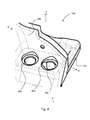
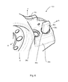
- a mount of this type (mount 24d) is shown more clearly in another embodiment illustrated in Figures 8 and 9 .
- the mount 24a/d has a circular central section 50a/d with holes 52a/d spaced circumferentially around the central section. The holes 52a/d can receive bolts (not shown) to bolt the mount to a mounting for a drum brake.
- An upper end of the mount 24a/d (as viewed in the figures) is provided with a support 54a/d that extends chordally each side of the central section for supporting a carrier 12a/d.
- the support 54d comprises a planar surface 28a that abuts a planar surface 26a of the carrier.
- the planar surfaces 26a and 28a are positioned on either side of the carrier 12a and the mount 24a, i.e. chordally either side of an axle, and are coplanar.
- the planar surfaces 26a, 28a on each side of the carrier 12a and mount 24a may be angled with respect to each other.
- the planar surfaces 26a, 28a at one side may be substantially perpendicular to a planar surfaces 26a, 28a at the other side of the carrier 12a and mount 24a.
- Direction A is a direction through an axis of rotation of a rotor of a disc brake and is substantially perpendicular to a plane substantially parallel to a planar face of the rotor, referring to Figure 8 , in this embodiment the rotor (not shown) of a disc brake will be positioned to be in a plane substantially parallel to the plane defined by the circular central section 50d.
- Direction T is a direction tangential to a circle described by rotation of a rotor of a disc brake (which in the embodiment shown in Figure 8 is also tangential to the central circular section 50d) and generally parallel or aligned with a direction of insertion or removal of a friction element into or from the carrier.
- one friction element is inserted into one of an upper rectangular receiving region or window 56d on each axial side of the carrier, and the direction of insertion or removal of a friction element is, in this embodiment, aligned with two opposing sides 58d of the rectangular receiving region 56d and is indicated in Figure 8 by arrow I.
- Direction R is a direction substantially perpendicular to both of the axes defined by direction A and direction T respectively (i.e. is generally aligned with a width of the carrier).
- the grooves 30a, 32a are linear, longitudinal grooves each with a semi-circular cross section.
- the grooves 30a, 32a extend in the direction R.
- the groove 30a, 32a in the carrier and the mount are positioned such that when the carrier is correctly positioned with respect to the mount the grooves are coaxially aligned and form a conjoined location formation.
- the conjoined location formation is a channel with a circular cross section.
- a seat 34a is machined on either side of the groove 30a and the groove 32a. Such a machined seat 34a provides a surface profile and roughness correct for more accurate alignment of the two grooves 30a and 32a, and consequently more accurate alignment of the carrier with respect to the mount.
- the carrier is correctly positioned with respect to the mount, such that the groove 30a of the mount is aligned with the groove 32a of the carrier.
- a locator in this embodiment a dowel (not shown in Figure 3 ), is then positioned in the conjoined locator channel 31a.
- the dowel is a close fit to the locator channel 31a, a close fit may equate to a maximum clearance of 0.1 mm.
- the carrier is then attached to the mount using fasteners (not shown in Figure 3 ), in this embodiment the fasteners are bolts.
- the bolts screw from underneath the mount, with respect to the orientation of the carrier and mount assembly 10a shown in Figure 3 , into the carrier.
- any other suitable method of attaching the carrier to the mount may be used, for example welding.
- the dowel maintains the carrier and mount in correct alignment in both the direction T and the direction R.
- the dowel is removed from the assembly ready for normal use of the carrier and mount, i.e. mounted to an axle of a vehicle.
- the dowel may remain positioned in the conjoined channel 31a during normal use.
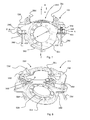
- FIG. 4 to 6 Alternative embodiments are shown in Figures 4 to 6 .
- the carrier and mount assemblies 10b, 10c are viewed from below the assembly, with respect to the positioning of the embodiment shown in Figure 3 .
- the carrier 12b, 12c is positioned on a mount 24b, 24c.
- a planar surface of the carrier abuts a planar surface of the mount 24b, 24c (the planar surfaces are not visible in the Figures, but the positioning of the carrier and mount is similar to that shown in Figure 3 ).
- bores 36b, 36c are formed in the mount 24b, 24c and the carrier 12b, 12c each for receiving a bolt to attach the carrier to the mount.
- Two of the bores 36b, 36c are positioned at one side of the assembly 10b, 10c and the other two bores (not shown in Figures 6 to 8 ) are spaced from said two bores to be positioned at an opposite side of the assembly 10b, 10c (i.e. an opposite side of an axle when the mount is attached thereto).
- the bores 36b, 36c longitudinally extend through the mount and carrier in the direction T. In this embodiment, the bores 36b, 36c extend entirely through the mount 24b, 24c and the carrier 12b, 12c.
- a slot 30b, 30c is formed in the mount 24b, 24c and the carrier 12b, 12c.
- the slot 30b, 30c extends through both the mount 24b, 24c and the carrier 12b, 12c.
- Each slot 30b, 30c is coaxially aligned with one of the four bores 36b, 36c.
- the bore 36b, 36c is threaded for engagement with a fastener, but there is no thread provided on the slot 30b, 30c.
- the slot 30b is substantially oval in shape and has a greater diameter than the bore 36b in the direction R, such that the slot protrudes from the profile of the bore at each side of the bore in the direction R.
- the slot 30c is substantially rectangular in shape and has a greater length than the diameter of the bore 36c in the direction R, such that the slot 30c protrudes from the profile of the bore 36c at each side of the bore in the direction R.
- the slot may have any suitable shape that has a directional component in a direction parallel to the plane of the rotor.
- a dowel 38c is positioned in the slot 30c.
- the dowel 38c is a close fit to the slot 30c.
- the dowel 38c has a rectangular cross section, but in alternative embodiments the cross section of the dowel may be selected to correspond to the cross-section of the slot 30c.
- the dowel 38c is driven through the slot 30c as the bolt (not shown in Figure 6 ) is screwed into the bore 36c, and exits through the opposite side of a slot 30c formed by the slot in the mount and the slot in the carrier.
- the dowel 38c may remain in a portion (e.g. an end portion) of the slot 30c.
- the slot 30c may not extend entirely through the mount 24c and the carrier 12c, and instead extend entirely through one of the mount 24c or carrier 12c and only partially through one of the carrier 12c or mount 24c, respectively.
- the carrier is positioned on the mount.
- the dowel is then positioned in the slot, to ensure correct alignment.
- a bolt is then screwed into the adjacent, slot-free bore.
- a bolt is screwed into the bore coaxial with the slot.
- the bolts may be tightened in a different order or simultaneously.
- a further alternative embodiment of a carrier and mount assembly of a disc brake is indicated generally at 10d in Figures 7 and 8 .
- a carrier 12d is positioned on a mount 24d.
- a planar surface of the carrier 12d abuts a planar surface of the mount 24d (the planar surfaces are not visible in Figures 7 and 8 , but the positioning of the mount with respect to the carrier is similar to that shown in Figure 3 ).
- a hole 30d extends entirely through the mount 24d and a hole 32d extends partially through the carrier 12d.
- the holes 30d, 32d are linear holes positioned to have a longitudinal length in the direction T.
- a hole 30d, 32d is positioned on either side (i.e. each side of an axle when attached to an axle) of the mount and the carrier.
- the hole 30d, 32d is threaded, but in alternative embodiments the holes 30d, 32d do not have a threaded surface.
- the hole 30d of the mount 24d is coaxially aligned with the hole 32d of the carrier 12d.
- the hole 30d may extend partially through the mount 24d and the hole 32d may extend entirely through the carrier 12d.
- a locator in this embodiment a bolt 38d is screwed into each of the holes 30d, 32d.
- the bolt 38d is a close fit to the holes 30d, 32d.
- the bolts or pins may be plain or doppler (also known as "quick release") bolts or pins that utilise e.g retractable ball bearing detents to releasably hold them in place, an example of a suitable pin is available from Speciality Fasteners and Components Limited of Totnes, Devon, UK, and is of the 420, 425, 620, 625, 13270 or 13275 series.
- bolts 40d are then screwed into the mount 24d and carrier 12d to attach the carrier 12d to the mount 24d.
- the bolt 38d is then removed, but in alternative embodiments the bolt 38d may remain in position during use. In such embodiments the bolt provided would be shorter in length than the bolt shown in Figures 7 and 8 .
- FIG. 9 A further embodiment is shown in Figures 9 and 10 .
- a carrier 12e is positioned on a mount 24e, such that a planar surface of the carrier is seated on a planar surface of the mount 24e (the positioning of the carrier, mount and planar surfaces is similar to that shown in Figure 3 so will not be explained further here).
- a location formation in this embodiment a groove 30e is positioned on two sides of the mount 24e.
- the two said sides of the mount 24e are orientated in a plane having axes parallel to an axis of rotation of a rotor of a disc brake and parallel to a direction tangential to a rotation of the rotor of a disc brake.
- a groove 32e is positioned on two sides of the carrier.
- the grooves 30e and 32e are linear grooves having a longitudinal length generally in a direction T tangential to a direction of rotation of a rotor of a disc brake.
- the grooves have a semi-circular cross section, but any appropriate cross section may be provided.
- the grooves are formed by milling.
- the groove 32e of the carrier 12e is positioned in coaxial alignment with the groove 30e of the mount 24e.
- a clamp having a locator component is positioned such that the locator component is positioned in the grooves 30e, 32e, and the carrier 12e is clamped to the mount 24e. Whilst the carrier 12e is clamped to the mount 24e, the carrier 12e is attached to the mount 24e, for example using fasteners such as bolts.
- the clamp applies the clamping force in a direction substantially perpendicular to the location formations and substantially perpendicular to an axis of rotation of the rotor, i.e. in the direction R.
- FIG. 11 to 14 A further embodiment is shown in Figures 11 to 14 .
- a carrier 12f is positioned on a mount 24f, such that a planar surface of the carrier is seated on a planar surface of the mount 24f (the positioning of the carrier, mount and planar surfaces is similar to that shown in Figure 3 so will not be explained further here).
- the mount 24f includes four through holes 72f, 74f, 76f, 78f, and the carrier 12f includes four through holes 80f, 82f, 84f and 86f.
- the through holes of the mount are coaxial with the through holes of a carrier to receive a fastener (not shown in Figures 11 to 14 ).
- the four holes 72f, 76f, 74f, 78f of the mount are arranged so that two holes are on either side of a plane defined by an axis extending substantially parallel to a direction T of insertion or removal of a friction element into or from the carrier, and an axis of rotation of a rotor of a disc brake.
- the four holes of the carrier 80f, 82f, 84f, 86f are similarly arranged.
- the holes 72f, 74f in the mount nearest an axis of rotation of a rotor include a section 66f, 30f having an enlarged diameter, and the holes 80f, 84f in the carrier nearest the axis of rotation of the rotor included a section 68f, 32f having an enlarged diameter.
- the section of the carrier having the enlarged diameter is positioned adjacent the section of the mount having an enlarged diameter when the carrier is mounted to the mount.
- One or more of the narrower section of the holes 72f, 74f, 80f, 82f is threaded to mate with a fastener, which in this embodiment is a threaded bolt.
- the enlarged diameter section is free from thread.
- a bush 68f is positioned in the enlarged sections 68f, 66f on a leading side of the rotor (with respect to the usual direction of rotation of the rotor during use), and the bush 38f is positioned in the enlarged sections 32f, 30f on the on a trailing side of the rotor (with respect to the usual direction of rotation of the rotor during use).
- the bushes 38f, 68f are split bushes include a chamfered end nearest the mount, i.e. a leading end during assembly.
- the split bushes are made from spring steel.
- the bush 38f forms a locator and the enlarged sections 30f and 32f form location formations.
- the bush 38f is formed to be a transitional fit to the enlarged sections 30f and 32f.
- the outer diameter of the bush 38f is substantially equal to the outer diameter of the enlarged section 30f, 32f, but in alternative embodiments alternative transitional fits may be used, or the bush may have a relaxed outer diameter greater than the enlarged section 30f, 32f.
- a transitional fit may be a fit having a clearance of between 0 mm and 0.1 mm. However, as will be appreciated by the person skilled in the art the size of the clearance will depend on the diameter of the bush.
- the bush 68f is a transitional fit to the enlarged section 68f of the carrier, but is a loose fit to the enlarged section 66f of the mount 24f.
- there is a clearance between the bush 68f and the enlarged section 68f of the mount of approximately 0.7 mm.
- the clearance may be greater than approximately 0.4 mm.
- the size of the clearance will depend on the diameter of the bush.
- the bushes 38f, 68f are positioned in the enlarged sections 32f, 68f of the holes 82f, 80f.
- the carrier 12f is then seated on the mount and the bushes 38f, 68f are positioned in the enlarged sections 30f, 66f of the holes 74f, 72f of the mount 24f.
- the chamfer on the leading end of the bushes 38f, 68f eases insertion of the bushes into the enlarged sections of the mount.
- the chamfer on the leading end provides a lead in to the hole, that eases compression of the split bush 38f so that the bush can be more easily inserted into the enlarged section 30f.
- the split bush expands to have an outer diameter substantially equal to the outer diameter of the enlarged section 32f of the carrier and/or of the enlarged section 30f of the carrier.
- Fasteners (not shown), in the present embodiment bolts, are then fastened through the holes 72f, 74f, 76f, 78f, 80f 82f, 84f, 86f in the carrier 12f and mount 24f to secure the carrier 12f to the mount 24f.
- one bush that is a transitional or tight fit to the mount and one bush that is a loose fit to the mount eases assembly of the carrier and mount assembly 10f because alignment of the carrier to the mount is simplified. Assembly can be further simplified when the bush 38f is a transitional fit rather than the bush having a relaxed diameter greater than the diameter of the enlarged section.
- removal of the locator for normal use can reduce the weight of the disc brake in normal use.
- the grooves or holes may have any appropriate cross section.
- the grooves may have a curved or stepped profile in a longitudinal direction.
- the mount may be a bracket secured by welding to an axle.
- the mount may be part of a steering knuckle on a steered axle.
- the carrier is shown in this embodiment as not having a beam connecting the opposing sides 58d of the rectangular receiving region, but in other embodiments such a beam may be provided.
- the locator is tapered.
- the locator may be a dowel having tapered side walls.
- the dowel may be conical in shape.
- the location formations may also be tapered to accommodate the tapered locator.
- a taper can guide the locator into correct position in the location formation, which can guide the carrier into correct alignment with the mount.
Landscapes
- Engineering & Computer Science (AREA)
- General Engineering & Computer Science (AREA)
- Mechanical Engineering (AREA)
- Braking Arrangements (AREA)
Priority Applications (1)
| Application Number | Priority Date | Filing Date | Title |
|---|---|---|---|
| EP13177534.8A EP2690303B1 (de) | 2012-07-24 | 2013-07-23 | Träger und Montiereinheit |
Applications Claiming Priority (2)
| Application Number | Priority Date | Filing Date | Title |
|---|---|---|---|
| EP12177731.2A EP2690302B1 (de) | 2012-07-24 | 2012-07-24 | Träger und Montiereinheit |
| EP13177534.8A EP2690303B1 (de) | 2012-07-24 | 2013-07-23 | Träger und Montiereinheit |
Publications (2)
| Publication Number | Publication Date |
|---|---|
| EP2690303A1 true EP2690303A1 (de) | 2014-01-29 |
| EP2690303B1 EP2690303B1 (de) | 2017-07-19 |
Family
ID=48794024
Family Applications (3)
| Application Number | Title | Priority Date | Filing Date |
|---|---|---|---|
| EP17162967.8A Withdrawn EP3205899A1 (de) | 2012-07-24 | 2012-07-24 | Träger und halterung |
| EP12177731.2A Active EP2690302B1 (de) | 2012-07-24 | 2012-07-24 | Träger und Montiereinheit |
| EP13177534.8A Revoked EP2690303B1 (de) | 2012-07-24 | 2013-07-23 | Träger und Montiereinheit |
Family Applications Before (2)
| Application Number | Title | Priority Date | Filing Date |
|---|---|---|---|
| EP17162967.8A Withdrawn EP3205899A1 (de) | 2012-07-24 | 2012-07-24 | Träger und halterung |
| EP12177731.2A Active EP2690302B1 (de) | 2012-07-24 | 2012-07-24 | Träger und Montiereinheit |
Country Status (3)
| Country | Link |
|---|---|
| US (3) | US20140027214A1 (de) |
| EP (3) | EP3205899A1 (de) |
| BR (2) | BR102013013679B1 (de) |
Families Citing this family (9)
| Publication number | Priority date | Publication date | Assignee | Title |
|---|---|---|---|---|
| EP3205899A1 (de) * | 2012-07-24 | 2017-08-16 | Meritor Heavy Vehicle Braking Systems (UK) Limited | Träger und halterung |
| DE102015002892A1 (de) | 2015-03-05 | 2016-09-08 | Wabco Europe Bvba | Achse eines Landfahrzeugs, Landfahrzeug mit einer solchen Achse sowie Scheibenbremse und Bremsenträger eines solchen Landfahrzeugs |
| USD771540S1 (en) * | 2015-06-15 | 2016-11-15 | Saf-Holland, Inc. | Brake spider |
| EP3121477B1 (de) * | 2015-07-21 | 2022-10-05 | Meritor Heavy Vehicle Braking Systems (UK) Limited | Scheibenbremsanordnung |
| USD836505S1 (en) * | 2015-08-31 | 2018-12-25 | Cummins Inc. | Compression relief brake assembly |
| EP3492767B1 (de) * | 2017-11-29 | 2020-11-18 | Meritor Heavy Vehicle Braking Systems (UK) Limited | Scheibenbremse |
| EP3499073A1 (de) * | 2017-12-15 | 2019-06-19 | Meritor Heavy Vehicle Braking Systems (UK) Limited | Bremssattel |
| EP3779222B1 (de) * | 2019-08-13 | 2024-04-03 | Meritor Heavy Vehicle Braking Systems (UK) Limited | Scheibenbremse |
| US20230272829A1 (en) * | 2022-02-25 | 2023-08-31 | Bendix Commercial Vehicle Systems Llc | Friction Pad Carrier for a Disc Brake |
Citations (4)
| Publication number | Priority date | Publication date | Assignee | Title |
|---|---|---|---|---|
| DE4303417A1 (de) * | 1993-02-05 | 1994-08-11 | Knorr Bremse Ag | Befestigungsvorrichtung für Scheibenbremsen |
| EP1437521A1 (de) * | 2003-01-07 | 2004-07-14 | Peugeot Citroen Automobiles SA | Vorrichtung zur Befestigung des Bremssattels einer Scheibenbremse auf einem Achsschenkel, insbesondere für ein Kraftfahrzeug |
| US20080135352A1 (en) * | 2006-12-12 | 2008-06-12 | Bendix Spicer Foundation Brake Llc | Brake caliper vertical mounting assembly joint arrangement |
| FR2976038A1 (fr) * | 2011-05-31 | 2012-12-07 | Peugeot Citroen Automobiles Sa | Dispositif de freinage a etrier flottant avec montage radial direct ou indirect de l'etrier |
Family Cites Families (12)
| Publication number | Priority date | Publication date | Assignee | Title |
|---|---|---|---|---|
| JP3428445B2 (ja) | 1998-07-06 | 2003-07-22 | 住友電気工業株式会社 | ラジアルマウント型ディスクブレーキ |
| DE10218116B4 (de) * | 2002-04-23 | 2004-04-15 | Siemens Ag | Anordnung aus Kunststoffteil und metallischem Einsatz |
| DE202004013006U1 (de) * | 2004-07-15 | 2004-11-04 | Otto Sauer Achsenfabrik Keilberg | Bremseinrichtung mit Bremssattelbefestigung |
| DE102004045223B3 (de) * | 2004-09-17 | 2006-06-08 | Wabco Radbremsen Gmbh | Bremsenträger |
| US20060237267A1 (en) | 2005-04-21 | 2006-10-26 | Brown Michael R Ii | Vertical mounting of air disk brake caliper assembly |
| DE102005052951B4 (de) | 2005-11-03 | 2015-01-22 | Bpw Bergische Achsen Kg | Verfahren und Werkzeug zur Montage/Demontage von Bremsscheiben |
| DE102005059247B4 (de) * | 2005-12-12 | 2008-04-30 | Knorr-Bremse Systeme für Nutzfahrzeuge GmbH | Bremsvorrichtung |
| SE530658C2 (sv) * | 2006-12-27 | 2008-08-05 | Scania Cv Abp | Sätt och anordning för montering av bromsok jämte fordon |
| US20080247843A1 (en) * | 2007-03-26 | 2008-10-09 | Shluzas Robert J | Fastening system |
| DE102008047913B3 (de) * | 2008-09-19 | 2010-04-01 | Wabco Radbremsen Gmbh | Scheibenbremse, Radträger, Baugruppe mit einer Scheibenbremse und einem Radträger sowie Fahrzeug |
| EP3205899A1 (de) * | 2012-07-24 | 2017-08-16 | Meritor Heavy Vehicle Braking Systems (UK) Limited | Träger und halterung |
| DE102013013030B4 (de) | 2013-08-05 | 2015-05-21 | Knorr-Bremse Systeme für Nutzfahrzeuge GmbH | Scheibenbremse für ein Nutzfahrzeug |
-
2012
- 2012-07-24 EP EP17162967.8A patent/EP3205899A1/de not_active Withdrawn
- 2012-07-24 EP EP12177731.2A patent/EP2690302B1/de active Active
-
2013
- 2013-05-31 US US13/906,603 patent/US20140027214A1/en not_active Abandoned
- 2013-06-03 BR BR102013013679-4A patent/BR102013013679B1/pt active IP Right Grant
- 2013-06-03 BR BR122015000250-8A patent/BR122015000250B1/pt active IP Right Grant
- 2013-07-23 EP EP13177534.8A patent/EP2690303B1/de not_active Revoked
-
2015
- 2015-03-12 US US14/645,981 patent/US9447829B2/en active Active
- 2015-03-12 US US14/645,880 patent/US9447828B2/en active Active
Patent Citations (4)
| Publication number | Priority date | Publication date | Assignee | Title |
|---|---|---|---|---|
| DE4303417A1 (de) * | 1993-02-05 | 1994-08-11 | Knorr Bremse Ag | Befestigungsvorrichtung für Scheibenbremsen |
| EP1437521A1 (de) * | 2003-01-07 | 2004-07-14 | Peugeot Citroen Automobiles SA | Vorrichtung zur Befestigung des Bremssattels einer Scheibenbremse auf einem Achsschenkel, insbesondere für ein Kraftfahrzeug |
| US20080135352A1 (en) * | 2006-12-12 | 2008-06-12 | Bendix Spicer Foundation Brake Llc | Brake caliper vertical mounting assembly joint arrangement |
| FR2976038A1 (fr) * | 2011-05-31 | 2012-12-07 | Peugeot Citroen Automobiles Sa | Dispositif de freinage a etrier flottant avec montage radial direct ou indirect de l'etrier |
Also Published As
| Publication number | Publication date |
|---|---|
| BR122015000250A2 (pt) | 2015-12-29 |
| US20150184706A1 (en) | 2015-07-02 |
| EP2690303B1 (de) | 2017-07-19 |
| US20140027214A1 (en) | 2014-01-30 |
| BR102013013679A2 (pt) | 2015-11-10 |
| US20150184705A1 (en) | 2015-07-02 |
| BR122015000250B1 (pt) | 2022-03-22 |
| US9447828B2 (en) | 2016-09-20 |
| EP2690302A1 (de) | 2014-01-29 |
| US9447829B2 (en) | 2016-09-20 |
| BR102013013679B1 (pt) | 2021-08-10 |
| BR102013013679A8 (pt) | 2021-04-13 |
| EP3205899A1 (de) | 2017-08-16 |
| EP2690302B1 (de) | 2017-03-29 |
Similar Documents
| Publication | Publication Date | Title |
|---|---|---|
| EP2690303B1 (de) | Träger und Montiereinheit | |
| US5343985A (en) | Floating-caliper spot-type disc brake for high-powered vehicles | |
| EP2260215B1 (de) | An einem aussenbordnabenzylinder montierter rotor | |
| US5842388A (en) | Vehicle hub and brake machining method | |
| US9429201B2 (en) | Braking device with a brake caliper attachment | |
| US20080135352A1 (en) | Brake caliper vertical mounting assembly joint arrangement | |
| EP2942541B1 (de) | Führungsanordnung für eine Scheibenbremse | |
| EP1516132B1 (de) | Bremsdrehmomentplatte und installationsverfahren | |
| US20070119665A1 (en) | Outer pad abutment design for frame type calipers | |
| US11560929B2 (en) | Guide assembly for a disc brake | |
| US20110247905A1 (en) | Brake caliper | |
| EP0062403A1 (de) | Scheibenbremssattel | |
| JPH0213179B2 (de) | ||
| KR20080018610A (ko) | 차량용 브레이크 디스크-휠 베어링 조립체 | |
| US10451127B2 (en) | Utility vehicle disk brake | |
| US20210172485A1 (en) | Commercial vehicle axle with a disc brake | |
| US20230166807A1 (en) | Brake mounts for bicycles | |
| US20230375050A1 (en) | Brake Application Mechanism of a Disc Brake | |
| US7739795B1 (en) | Method of manufacturing a corner module assembly | |
| US10605317B2 (en) | Fixing for a brake carrier and a mount for a disc brake and method thereof | |
| KR20210025279A (ko) | 휠베어링 조립체 및 이를 구비한 휠베어링 장치 |
Legal Events
| Date | Code | Title | Description |
|---|---|---|---|
| PUAI | Public reference made under article 153(3) epc to a published international application that has entered the european phase |
Free format text: ORIGINAL CODE: 0009012 |
|
| AK | Designated contracting states |
Kind code of ref document: A1 Designated state(s): AL AT BE BG CH CY CZ DE DK EE ES FI FR GB GR HR HU IE IS IT LI LT LU LV MC MK MT NL NO PL PT RO RS SE SI SK SM TR |
|
| AX | Request for extension of the european patent |
Extension state: BA ME |
|
| 17P | Request for examination filed |
Effective date: 20140725 |
|
| RBV | Designated contracting states (corrected) |
Designated state(s): AL AT BE BG CH CY CZ DE DK EE ES FI FR GB GR HR HU IE IS IT LI LT LU LV MC MK MT NL NO PL PT RO RS SE SI SK SM TR |
|
| RIN1 | Information on inventor provided before grant (corrected) |
Inventor name: SYLWAN, MARTEN Inventor name: OLSSON, CARL-OTTO Inventor name: BULL, ADRIAN |
|
| RAP1 | Party data changed (applicant data changed or rights of an application transferred) |
Owner name: SCANIA CV AB Owner name: MERITOR HEAVY VEHICLE BRAKING SYSTEMS (UK) LIMITED |
|
| 17Q | First examination report despatched |
Effective date: 20160413 |
|
| GRAP | Despatch of communication of intention to grant a patent |
Free format text: ORIGINAL CODE: EPIDOSNIGR1 |
|
| STAA | Information on the status of an ep patent application or granted ep patent |
Free format text: STATUS: GRANT OF PATENT IS INTENDED |
|
| INTG | Intention to grant announced |
Effective date: 20170201 |
|
| GRAS | Grant fee paid |
Free format text: ORIGINAL CODE: EPIDOSNIGR3 |
|
| GRAA | (expected) grant |
Free format text: ORIGINAL CODE: 0009210 |
|
| STAA | Information on the status of an ep patent application or granted ep patent |
Free format text: STATUS: THE PATENT HAS BEEN GRANTED |
|
| AK | Designated contracting states |
Kind code of ref document: B1 Designated state(s): AL AT BE BG CH CY CZ DE DK EE ES FI FR GB GR HR HU IE IS IT LI LT LU LV MC MK MT NL NO PL PT RO RS SE SI SK SM TR |
|
| REG | Reference to a national code |
Ref country code: GB Ref legal event code: FG4D |
|
| REG | Reference to a national code |
Ref country code: FR Ref legal event code: PLFP Year of fee payment: 5 |
|
| REG | Reference to a national code |
Ref country code: CH Ref legal event code: EP |
|
| REG | Reference to a national code |
Ref country code: IE Ref legal event code: FG4D |
|
| REG | Reference to a national code |
Ref country code: AT Ref legal event code: REF Ref document number: 910700 Country of ref document: AT Kind code of ref document: T Effective date: 20170815 |
|
| REG | Reference to a national code |
Ref country code: DE Ref legal event code: R096 Ref document number: 602013023639 Country of ref document: DE |
|
| REG | Reference to a national code |
Ref country code: SE Ref legal event code: TRGR |
|
| REG | Reference to a national code |
Ref country code: NL Ref legal event code: MP Effective date: 20170719 |
|
| REG | Reference to a national code |
Ref country code: LT Ref legal event code: MG4D |
|
| REG | Reference to a national code |
Ref country code: AT Ref legal event code: MK05 Ref document number: 910700 Country of ref document: AT Kind code of ref document: T Effective date: 20170719 |
|
| PG25 | Lapsed in a contracting state [announced via postgrant information from national office to epo] |
Ref country code: HR Free format text: LAPSE BECAUSE OF FAILURE TO SUBMIT A TRANSLATION OF THE DESCRIPTION OR TO PAY THE FEE WITHIN THE PRESCRIBED TIME-LIMIT Effective date: 20170719 Ref country code: LT Free format text: LAPSE BECAUSE OF FAILURE TO SUBMIT A TRANSLATION OF THE DESCRIPTION OR TO PAY THE FEE WITHIN THE PRESCRIBED TIME-LIMIT Effective date: 20170719 Ref country code: AT Free format text: LAPSE BECAUSE OF FAILURE TO SUBMIT A TRANSLATION OF THE DESCRIPTION OR TO PAY THE FEE WITHIN THE PRESCRIBED TIME-LIMIT Effective date: 20170719 Ref country code: NO Free format text: LAPSE BECAUSE OF FAILURE TO SUBMIT A TRANSLATION OF THE DESCRIPTION OR TO PAY THE FEE WITHIN THE PRESCRIBED TIME-LIMIT Effective date: 20171019 Ref country code: FI Free format text: LAPSE BECAUSE OF FAILURE TO SUBMIT A TRANSLATION OF THE DESCRIPTION OR TO PAY THE FEE WITHIN THE PRESCRIBED TIME-LIMIT Effective date: 20170719 Ref country code: NL Free format text: LAPSE BECAUSE OF FAILURE TO SUBMIT A TRANSLATION OF THE DESCRIPTION OR TO PAY THE FEE WITHIN THE PRESCRIBED TIME-LIMIT Effective date: 20170719 |
|
| PG25 | Lapsed in a contracting state [announced via postgrant information from national office to epo] |
Ref country code: BG Free format text: LAPSE BECAUSE OF FAILURE TO SUBMIT A TRANSLATION OF THE DESCRIPTION OR TO PAY THE FEE WITHIN THE PRESCRIBED TIME-LIMIT Effective date: 20171019 Ref country code: IS Free format text: LAPSE BECAUSE OF FAILURE TO SUBMIT A TRANSLATION OF THE DESCRIPTION OR TO PAY THE FEE WITHIN THE PRESCRIBED TIME-LIMIT Effective date: 20171119 Ref country code: LV Free format text: LAPSE BECAUSE OF FAILURE TO SUBMIT A TRANSLATION OF THE DESCRIPTION OR TO PAY THE FEE WITHIN THE PRESCRIBED TIME-LIMIT Effective date: 20170719 Ref country code: RS Free format text: LAPSE BECAUSE OF FAILURE TO SUBMIT A TRANSLATION OF THE DESCRIPTION OR TO PAY THE FEE WITHIN THE PRESCRIBED TIME-LIMIT Effective date: 20170719 Ref country code: ES Free format text: LAPSE BECAUSE OF FAILURE TO SUBMIT A TRANSLATION OF THE DESCRIPTION OR TO PAY THE FEE WITHIN THE PRESCRIBED TIME-LIMIT Effective date: 20170719 Ref country code: PL Free format text: LAPSE BECAUSE OF FAILURE TO SUBMIT A TRANSLATION OF THE DESCRIPTION OR TO PAY THE FEE WITHIN THE PRESCRIBED TIME-LIMIT Effective date: 20170719 Ref country code: GR Free format text: LAPSE BECAUSE OF FAILURE TO SUBMIT A TRANSLATION OF THE DESCRIPTION OR TO PAY THE FEE WITHIN THE PRESCRIBED TIME-LIMIT Effective date: 20171020 |
|
| REG | Reference to a national code |
Ref country code: CH Ref legal event code: PL |
|
| REG | Reference to a national code |
Ref country code: DE Ref legal event code: R026 Ref document number: 602013023639 Country of ref document: DE |
|
| REG | Reference to a national code |
Ref country code: IE Ref legal event code: MM4A |
|
| PLBI | Opposition filed |
Free format text: ORIGINAL CODE: 0009260 |
|
| PG25 | Lapsed in a contracting state [announced via postgrant information from national office to epo] |
Ref country code: RO Free format text: LAPSE BECAUSE OF FAILURE TO SUBMIT A TRANSLATION OF THE DESCRIPTION OR TO PAY THE FEE WITHIN THE PRESCRIBED TIME-LIMIT Effective date: 20170719 Ref country code: DK Free format text: LAPSE BECAUSE OF FAILURE TO SUBMIT A TRANSLATION OF THE DESCRIPTION OR TO PAY THE FEE WITHIN THE PRESCRIBED TIME-LIMIT Effective date: 20170719 Ref country code: CH Free format text: LAPSE BECAUSE OF NON-PAYMENT OF DUE FEES Effective date: 20170731 Ref country code: MC Free format text: LAPSE BECAUSE OF FAILURE TO SUBMIT A TRANSLATION OF THE DESCRIPTION OR TO PAY THE FEE WITHIN THE PRESCRIBED TIME-LIMIT Effective date: 20170719 Ref country code: CZ Free format text: LAPSE BECAUSE OF FAILURE TO SUBMIT A TRANSLATION OF THE DESCRIPTION OR TO PAY THE FEE WITHIN THE PRESCRIBED TIME-LIMIT Effective date: 20170719 Ref country code: IE Free format text: LAPSE BECAUSE OF NON-PAYMENT OF DUE FEES Effective date: 20170723 Ref country code: LI Free format text: LAPSE BECAUSE OF NON-PAYMENT OF DUE FEES Effective date: 20170731 |
|
| PLAX | Notice of opposition and request to file observation + time limit sent |
Free format text: ORIGINAL CODE: EPIDOSNOBS2 |
|
| 26 | Opposition filed |
Opponent name: KNORR-BREMSE SYSTEME FUER SCHIENENFAHRZEUGE GMBH Effective date: 20180417 |
|
| PG25 | Lapsed in a contracting state [announced via postgrant information from national office to epo] |
Ref country code: SK Free format text: LAPSE BECAUSE OF FAILURE TO SUBMIT A TRANSLATION OF THE DESCRIPTION OR TO PAY THE FEE WITHIN THE PRESCRIBED TIME-LIMIT Effective date: 20170719 Ref country code: EE Free format text: LAPSE BECAUSE OF FAILURE TO SUBMIT A TRANSLATION OF THE DESCRIPTION OR TO PAY THE FEE WITHIN THE PRESCRIBED TIME-LIMIT Effective date: 20170719 Ref country code: IT Free format text: LAPSE BECAUSE OF FAILURE TO SUBMIT A TRANSLATION OF THE DESCRIPTION OR TO PAY THE FEE WITHIN THE PRESCRIBED TIME-LIMIT Effective date: 20170719 Ref country code: SM Free format text: LAPSE BECAUSE OF FAILURE TO SUBMIT A TRANSLATION OF THE DESCRIPTION OR TO PAY THE FEE WITHIN THE PRESCRIBED TIME-LIMIT Effective date: 20170719 |
|
| REG | Reference to a national code |
Ref country code: BE Ref legal event code: MM Effective date: 20170731 |
|
| PG25 | Lapsed in a contracting state [announced via postgrant information from national office to epo] |
Ref country code: LU Free format text: LAPSE BECAUSE OF NON-PAYMENT OF DUE FEES Effective date: 20170723 |
|
| REG | Reference to a national code |
Ref country code: FR Ref legal event code: PLFP Year of fee payment: 6 |
|
| PG25 | Lapsed in a contracting state [announced via postgrant information from national office to epo] |
Ref country code: BE Free format text: LAPSE BECAUSE OF NON-PAYMENT OF DUE FEES Effective date: 20170731 Ref country code: SI Free format text: LAPSE BECAUSE OF FAILURE TO SUBMIT A TRANSLATION OF THE DESCRIPTION OR TO PAY THE FEE WITHIN THE PRESCRIBED TIME-LIMIT Effective date: 20170719 |
|
| PLBB | Reply of patent proprietor to notice(s) of opposition received |
Free format text: ORIGINAL CODE: EPIDOSNOBS3 |
|
| PG25 | Lapsed in a contracting state [announced via postgrant information from national office to epo] |
Ref country code: MT Free format text: LAPSE BECAUSE OF NON-PAYMENT OF DUE FEES Effective date: 20170723 |
|
| PG25 | Lapsed in a contracting state [announced via postgrant information from national office to epo] |
Ref country code: HU Free format text: LAPSE BECAUSE OF FAILURE TO SUBMIT A TRANSLATION OF THE DESCRIPTION OR TO PAY THE FEE WITHIN THE PRESCRIBED TIME-LIMIT; INVALID AB INITIO Effective date: 20130723 |
|
| PG25 | Lapsed in a contracting state [announced via postgrant information from national office to epo] |
Ref country code: CY Free format text: LAPSE BECAUSE OF NON-PAYMENT OF DUE FEES Effective date: 20170719 |
|
| PG25 | Lapsed in a contracting state [announced via postgrant information from national office to epo] |
Ref country code: MK Free format text: LAPSE BECAUSE OF FAILURE TO SUBMIT A TRANSLATION OF THE DESCRIPTION OR TO PAY THE FEE WITHIN THE PRESCRIBED TIME-LIMIT Effective date: 20170719 |
|
| APBM | Appeal reference recorded |
Free format text: ORIGINAL CODE: EPIDOSNREFNO |
|
| APBP | Date of receipt of notice of appeal recorded |
Free format text: ORIGINAL CODE: EPIDOSNNOA2O |
|
| APAH | Appeal reference modified |
Free format text: ORIGINAL CODE: EPIDOSCREFNO |
|
| PG25 | Lapsed in a contracting state [announced via postgrant information from national office to epo] |
Ref country code: TR Free format text: LAPSE BECAUSE OF FAILURE TO SUBMIT A TRANSLATION OF THE DESCRIPTION OR TO PAY THE FEE WITHIN THE PRESCRIBED TIME-LIMIT Effective date: 20170719 |
|
| APBQ | Date of receipt of statement of grounds of appeal recorded |
Free format text: ORIGINAL CODE: EPIDOSNNOA3O |
|
| PLAB | Opposition data, opponent's data or that of the opponent's representative modified |
Free format text: ORIGINAL CODE: 0009299OPPO |
|
| PG25 | Lapsed in a contracting state [announced via postgrant information from national office to epo] |
Ref country code: PT Free format text: LAPSE BECAUSE OF FAILURE TO SUBMIT A TRANSLATION OF THE DESCRIPTION OR TO PAY THE FEE WITHIN THE PRESCRIBED TIME-LIMIT Effective date: 20170719 |
|
| R26 | Opposition filed (corrected) |
Opponent name: KNORR-BREMSE SYSTEME FUER SCHIENENFAHRZEUGE GMBH Effective date: 20180417 |
|
| PLAB | Opposition data, opponent's data or that of the opponent's representative modified |
Free format text: ORIGINAL CODE: 0009299OPPO |
|
| PG25 | Lapsed in a contracting state [announced via postgrant information from national office to epo] |
Ref country code: AL Free format text: LAPSE BECAUSE OF FAILURE TO SUBMIT A TRANSLATION OF THE DESCRIPTION OR TO PAY THE FEE WITHIN THE PRESCRIBED TIME-LIMIT Effective date: 20170719 |
|
| R26 | Opposition filed (corrected) |
Opponent name: KNORR-BREMSE SYSTEME FUER NUTZFAHRZEUGE GMBH Effective date: 20180417 |
|
| RAP4 | Party data changed (patent owner data changed or rights of a patent transferred) |
Owner name: MERITOR HEAVY VEHICLE BRAKING SYSTEMS (UK) LIMITED Owner name: SCANIA CV AB |
|
| PGFP | Annual fee paid to national office [announced via postgrant information from national office to epo] |
Ref country code: DE Payment date: 20220727 Year of fee payment: 10 |
|
| PGFP | Annual fee paid to national office [announced via postgrant information from national office to epo] |
Ref country code: FR Payment date: 20220725 Year of fee payment: 10 |
|
| APBU | Appeal procedure closed |
Free format text: ORIGINAL CODE: EPIDOSNNOA9O |
|
| REG | Reference to a national code |
Ref country code: DE Ref legal event code: R103 Ref document number: 602013023639 Country of ref document: DE Ref country code: DE Ref legal event code: R064 Ref document number: 602013023639 Country of ref document: DE |
|
| P01 | Opt-out of the competence of the unified patent court (upc) registered |
Effective date: 20230531 |
|
| RDAF | Communication despatched that patent is revoked |
Free format text: ORIGINAL CODE: EPIDOSNREV1 |
|
| STAA | Information on the status of an ep patent application or granted ep patent |
Free format text: STATUS: PATENT REVOKED |
|
| RDAG | Patent revoked |
Free format text: ORIGINAL CODE: 0009271 |
|
| 27W | Patent revoked |
Effective date: 20230602 |
|
| GBPR | Gb: patent revoked under art. 102 of the ep convention designating the uk as contracting state |
Effective date: 20230602 |
|
| PGFP | Annual fee paid to national office [announced via postgrant information from national office to epo] |
Ref country code: GB Payment date: 20230727 Year of fee payment: 11 |
|
| PGFP | Annual fee paid to national office [announced via postgrant information from national office to epo] |
Ref country code: SE Payment date: 20230727 Year of fee payment: 11 |
|
| REG | Reference to a national code |
Ref country code: SE Ref legal event code: ECNC |