EP2690275A1 - Engine - Google Patents
Engine Download PDFInfo
- Publication number
- EP2690275A1 EP2690275A1 EP20130002902 EP13002902A EP2690275A1 EP 2690275 A1 EP2690275 A1 EP 2690275A1 EP 20130002902 EP20130002902 EP 20130002902 EP 13002902 A EP13002902 A EP 13002902A EP 2690275 A1 EP2690275 A1 EP 2690275A1
- Authority
- EP
- European Patent Office
- Prior art keywords
- chamber
- diaphragm
- piston
- pressure
- communicating passage
- Prior art date
- Legal status (The legal status is an assumption and is not a legal conclusion. Google has not performed a legal analysis and makes no representation as to the accuracy of the status listed.)
- Granted
Links
- 239000000446 fuel Substances 0.000 claims abstract description 121
- 230000002265 prevention Effects 0.000 claims abstract description 15
- 239000012530 fluid Substances 0.000 claims abstract description 9
- 238000004891 communication Methods 0.000 claims description 26
- 239000007788 liquid Substances 0.000 claims description 4
- 238000002485 combustion reaction Methods 0.000 description 12
- 230000006835 compression Effects 0.000 description 8
- 238000007906 compression Methods 0.000 description 8
- 230000008859 change Effects 0.000 description 7
- 230000000694 effects Effects 0.000 description 7
- 239000000428 dust Substances 0.000 description 6
- 238000000034 method Methods 0.000 description 6
- 239000007789 gas Substances 0.000 description 5
- 239000000203 mixture Substances 0.000 description 4
- 230000007246 mechanism Effects 0.000 description 3
- 238000005299 abrasion Methods 0.000 description 2
- 238000005516 engineering process Methods 0.000 description 2
- 239000002828 fuel tank Substances 0.000 description 2
- 230000004044 response Effects 0.000 description 2
- XLYOFNOQVPJJNP-UHFFFAOYSA-N water Substances O XLYOFNOQVPJJNP-UHFFFAOYSA-N 0.000 description 2
- IJGRMHOSHXDMSA-UHFFFAOYSA-N Atomic nitrogen Chemical compound N#N IJGRMHOSHXDMSA-UHFFFAOYSA-N 0.000 description 1
- 239000000853 adhesive Substances 0.000 description 1
- 230000001070 adhesive effect Effects 0.000 description 1
- 230000004075 alteration Effects 0.000 description 1
- 230000008901 benefit Effects 0.000 description 1
- 230000000593 degrading effect Effects 0.000 description 1
- 230000002542 deteriorative effect Effects 0.000 description 1
- 229910001873 dinitrogen Inorganic materials 0.000 description 1
- 239000011796 hollow space material Substances 0.000 description 1
- 238000004519 manufacturing process Methods 0.000 description 1
- 239000000463 material Substances 0.000 description 1
- 239000002184 metal Substances 0.000 description 1
- 238000012986 modification Methods 0.000 description 1
- 230000004048 modification Effects 0.000 description 1
- 239000002985 plastic film Substances 0.000 description 1
- 229920006255 plastic film Polymers 0.000 description 1
- 230000002195 synergetic effect Effects 0.000 description 1
Images











Classifications
-
- F—MECHANICAL ENGINEERING; LIGHTING; HEATING; WEAPONS; BLASTING
- F02—COMBUSTION ENGINES; HOT-GAS OR COMBUSTION-PRODUCT ENGINE PLANTS
- F02M—SUPPLYING COMBUSTION ENGINES IN GENERAL WITH COMBUSTIBLE MIXTURES OR CONSTITUENTS THEREOF
- F02M37/00—Apparatus or systems for feeding liquid fuel from storage containers to carburettors or fuel-injection apparatus; Arrangements for purifying liquid fuel specially adapted for, or arranged on, internal-combustion engines
- F02M37/04—Feeding by means of driven pumps
- F02M37/046—Arrangements for driving diaphragm-type pumps
-
- F—MECHANICAL ENGINEERING; LIGHTING; HEATING; WEAPONS; BLASTING
- F02—COMBUSTION ENGINES; HOT-GAS OR COMBUSTION-PRODUCT ENGINE PLANTS
- F02M—SUPPLYING COMBUSTION ENGINES IN GENERAL WITH COMBUSTIBLE MIXTURES OR CONSTITUENTS THEREOF
- F02M59/00—Pumps specially adapted for fuel-injection and not provided for in groups F02M39/00 -F02M57/00, e.g. rotary cylinder-block type of pumps
- F02M59/12—Pumps specially adapted for fuel-injection and not provided for in groups F02M39/00 -F02M57/00, e.g. rotary cylinder-block type of pumps having other positive-displacement pumping elements, e.g. rotary
- F02M59/14—Pumps specially adapted for fuel-injection and not provided for in groups F02M39/00 -F02M57/00, e.g. rotary cylinder-block type of pumps having other positive-displacement pumping elements, e.g. rotary of elastic-wall type
-
- F—MECHANICAL ENGINEERING; LIGHTING; HEATING; WEAPONS; BLASTING
- F02—COMBUSTION ENGINES; HOT-GAS OR COMBUSTION-PRODUCT ENGINE PLANTS
- F02M—SUPPLYING COMBUSTION ENGINES IN GENERAL WITH COMBUSTIBLE MIXTURES OR CONSTITUENTS THEREOF
- F02M17/00—Carburettors having pertinent characteristics not provided for in, or of interest apart from, the apparatus of preceding main groups F02M1/00 - F02M15/00
- F02M17/02—Floatless carburettors
- F02M17/04—Floatless carburettors having fuel inlet valve controlled by diaphragm
-
- F—MECHANICAL ENGINEERING; LIGHTING; HEATING; WEAPONS; BLASTING
- F02—COMBUSTION ENGINES; HOT-GAS OR COMBUSTION-PRODUCT ENGINE PLANTS
- F02M—SUPPLYING COMBUSTION ENGINES IN GENERAL WITH COMBUSTIBLE MIXTURES OR CONSTITUENTS THEREOF
- F02M1/00—Carburettors with means for facilitating engine's starting or its idling below operational temperatures
- F02M1/16—Other means for enriching fuel-air mixture during starting; Priming cups; using different fuels for starting and normal operation
-
- F—MECHANICAL ENGINEERING; LIGHTING; HEATING; WEAPONS; BLASTING
- F02—COMBUSTION ENGINES; HOT-GAS OR COMBUSTION-PRODUCT ENGINE PLANTS
- F02M—SUPPLYING COMBUSTION ENGINES IN GENERAL WITH COMBUSTIBLE MIXTURES OR CONSTITUENTS THEREOF
- F02M35/00—Combustion-air cleaners, air intakes, intake silencers, or induction systems specially adapted for, or arranged on, internal-combustion engines
- F02M35/02—Air cleaners
- F02M35/024—Air cleaners using filters, e.g. moistened
-
- F—MECHANICAL ENGINEERING; LIGHTING; HEATING; WEAPONS; BLASTING
- F02—COMBUSTION ENGINES; HOT-GAS OR COMBUSTION-PRODUCT ENGINE PLANTS
- F02M—SUPPLYING COMBUSTION ENGINES IN GENERAL WITH COMBUSTIBLE MIXTURES OR CONSTITUENTS THEREOF
- F02M37/00—Apparatus or systems for feeding liquid fuel from storage containers to carburettors or fuel-injection apparatus; Arrangements for purifying liquid fuel specially adapted for, or arranged on, internal-combustion engines
- F02M37/04—Feeding by means of driven pumps
- F02M37/14—Feeding by means of driven pumps the pumps being combined with other apparatus
-
- F—MECHANICAL ENGINEERING; LIGHTING; HEATING; WEAPONS; BLASTING
- F02—COMBUSTION ENGINES; HOT-GAS OR COMBUSTION-PRODUCT ENGINE PLANTS
- F02M—SUPPLYING COMBUSTION ENGINES IN GENERAL WITH COMBUSTIBLE MIXTURES OR CONSTITUENTS THEREOF
- F02M37/00—Apparatus or systems for feeding liquid fuel from storage containers to carburettors or fuel-injection apparatus; Arrangements for purifying liquid fuel specially adapted for, or arranged on, internal-combustion engines
- F02M37/04—Feeding by means of driven pumps
- F02M37/18—Feeding by means of driven pumps characterised by provision of main and auxiliary pumps
-
- F—MECHANICAL ENGINEERING; LIGHTING; HEATING; WEAPONS; BLASTING
- F02—COMBUSTION ENGINES; HOT-GAS OR COMBUSTION-PRODUCT ENGINE PLANTS
- F02M—SUPPLYING COMBUSTION ENGINES IN GENERAL WITH COMBUSTIBLE MIXTURES OR CONSTITUENTS THEREOF
- F02M5/00—Float-controlled apparatus for maintaining a constant fuel level
- F02M5/12—Other details, e.g. floats, valves, setting devices or tools
- F02M5/125—Shape of the jet needle
Definitions
- the present invention relates to an engine that drives a diaphragm fuel pump using negative pressure.
- Patent literatures 1 and 2 disclose a technology for driving a fuel pump (diaphragm fuel pump) of a two-stroke engine by using pressure fluctuation in an intake port as power source.
- Patent literatures 3, 4 and 5 disclose a technology for driving a diaphragm chamber of a diaphragm fuel pump by using positive pressure and negative pressure in a crank chamber as power source.
- Patent literature 1 Japanese Patent Application Laid-Open No. 2005-140027
- Patent literature 2 Japanese Patent Application Laid-Open No. HEI9-158806
- Patent literature 3 Japanese Patent Application Laid-Open No. HEI3-189363
- Patent literature 4 Japanese Patent Application Laid-Open No. 2003-172221
- Patent literature 5 Japanese Patent Application Laid-Open No. 2001-207914
- an obj ect of the present invention to provide an engine configured to prevent oil from flowing into a communicating passage for applying negative pressure, while providing the negative pressure from a negative pressure part to a diaphragm chamber of the diaphragm fuel pump.
- Another object of the present invention is to provide an engine configured to provide driving force generated by the pressure fluctuation in the pressure fluctuation part, to the diaphragm chamber of the diaphragm fuel pump, while preventing oil from flowing into a communicating passage that provides the pressure fluctuation to the diaphragm chamber.
- an engine includes: a piston; a carburetor having a diaphragm fuel pump , the diaphragm fuel pump including a pump chamber configured to suck and discharge fuel and a diaphragm chamber to which a pressure to drive the pump chamber is applied; and a communicating passage configured to connect between the diaphragm chamber and a negative pressure part in which a negative pressure is created due to movement of the piston.
- a flowback prevention part is formed in the communicating passage to allow fluid to move only in on direction from the diaphragm chamber to the negative pressure part.
- an engine includes: a piston; a carburetor; an elastic film; a first chamber formed in one side of the elastic film; a second chamber formed in the other side of the elastic film; and a diaphragm fuel pump provided in the carburetor, the diaphragm fuel pump including a pump chamber configured to suck and discharge fuel, and a diaphragm chamber to which a pressure to drive the pump chamber is applied.
- the first chamber communicates with a pressure fluctuation part in which there is pressure fluctuation due to movement of the piston, and the second chamber communicates with the diaphragm chamber.
- an engine configured to prevent oil from flowing into the communicating passage that provides pressure fluctuation to the diaphragm chamber, while providing driving force due to the pressure fluctuation in the pressure fluctuation part, to the diaphragm chamber of the diaphragm fuel pump.
- Fig. 1 is a schematic view showing the four-stroke engine according to Embodiment 1 of the present invention.
- Fig. 1 shows a four-stroke engine 1 in a state in which a piston is located in the vicinity of the top dead center (TDC).
- TDC top dead center
- the four-stroke engine 1 includes a cylinder part 3, a crankcase 5 mounted under the cylinder part 3 and an oil tank 15 provided below the crankcase 5.
- the cylinder part 3 has a cylindrical space to slidably move a piston 9 upward and downward in Fig. 1 .
- the piston 9 is fitted into the space with a gap to slidably move upward and downward in Fig. 1 .
- a crank chamber 7 is defined by the cylinder part 3, the crankcase 5 and the piston 9. That is, the crank chamber 7 is an approximately cylindrical space defined by the side surface of the cylinder part 3, the piston 9 and the crankcase 5. The volume of the inner space of this crank chamber 7 varies as the piston 9 slidably moves.
- a combustion chamber 8 is defined by the cylinder head 26, the cylinder part 3 and the piston 9.
- the oil tank 15 to store oil is provided separately from the crankcase 5.
- a crank chamber check valve 17 is provided between the oil tank 15 and the crankcase 5 to allow oil to flow only in one direction from the crankcase 5 (crank chamber 7) to the oil tank 15.
- a negative pressure is created in the crank chamber 7 as the piston 9 moves from the bottom dead center (BDC) to TDC.
- BDC bottom dead center
- a positive pressure is created in the crank chamber 7 as the piston 9 moves from TDC to BDC.
- a negative pressure is easily created in the crank chamber 7 because the crank chamber check valve 17 is provided, the pressure in the crank chamber 7 can rise only up to a positive pressure that overcomes the elasticity of a spring and so forth used in the crank chamber check valve 17.
- crank chamber 7 is a negative pressure part because a negative pressure is created in the crank chamber 7 when the piston 9 moves from BDC to TDC.
- the pressure in the crank chamber 7 changes once while a crank axle 13a rotates once. This is different from the pressure in an intake port or an exhaust port, which changes only once while the crank axle 13a rotates twice.
- a crank 13 is rotatably supported in the crankcase 5.
- This crank 13 is formed by the crank axle 13a which is the center of rotation, counterweight and so forth.
- the piston 9 and the crank 13 are connected one another via a connecting rod 11.
- the connecting rod 11 is rotatably connected to both the piston 9 and the crank 13. This configuration allows the piston 9 to reciprocally and slidably move in the cylinder part 3.
- a cylinder head 26 is provided on the upper wall of the cylinder part 3.
- the cylinder head 26 is provided with an intake port 27 that allows communication with the carburetor 25 and an exhaust port 33 that allows communication with an exhaust muffler (not shown).
- the cylinder head 26 is also provided with an intake valve 29 to open and close the intake port 27.
- the cylinder head 26 is provided with an exhaust valve 31 to open and close the exhaust port 33.
- a negative pressure is created in the intake port 27 every time the intake valve 29 opens and closes. Therefore, also the intake port 27 is a negative pressure part.
- An air cleaner 21 is provided outside the carburetor 25.
- a filter 23 is disposed in the air cleaner 21. The filter 23 allows air to pass through to remove dust and so forth in the air.
- the carburetor 25 is an apparatus to mix fuel into the air having passed through the air cleaner 21. To be more specific, the carburetor 25 can control mixing of the air and fuel and also control the total amount of the air-fuel mixture.
- the carburetor 25 has a diaphragm fuel pump 109 to mix fuel into the air. This diaphragm fuel pump 109 is driven by using pressure fluctuation as power.
- a diaphragm chamber 110 in the diaphragm fuel pump 109 is connected to the crank chamber 7 via a communicating passage 104 to supply the power to drive the diaphragm fuel pump 109.
- the diaphragm fuel pump 109 is provided with a diaphragm 108 whose position changes in response to pressure fluctuation.
- the communicating passage 104 is open in the cylinder part 3, it is by no means limiting but the communicating passage 104 may be open in a negative pressure part.
- the communicating passage 104 is open in the cylinder part 3, it is advantageous to supply a pulsed negative pressure to the diaphragm fuel pump 109. This will be described later.
- a crank chamber side opening 103 is provided in the communicating passage 104 in the crank chamber 7 side.
- an atmospheric pressure opening passage 107 is connected to the communicating passage 104.
- One end of the atmospheric pressure opening passage 107 has an air cleaner side opening 117 which opens in the air cleaner 21 (the space after the air has passed through the filter 23).
- the other end of the atmospheric pressure opening passage 107 opens on the way of the route of the communicating passage 104.
- the communicating passage 104 in the diaphragm chamber 110 side is referred to as a diaphragm chamber side communicating passage 113
- the communicating passage 104 in the crank chamber 7 side is referred to as a crank chamber side communicating passage 105.
- the atmospheric pressure opening passage 107 By providing the atmospheric pressure opening passage 107, even if oil and so forth enters the communication passage 104, it is possible to discharge the oil and so forth to the crank chamber 7 when a negative pressure is created in the crank chamber 7. It is because the air cleaner side opening 117 in the atmospheric pressure opening passage 107 opens in a space under atmospheric pressure. Therefore, when a negative pressure is created in the crank chamber 7, the air enters the crank chamber side opening 103 from the air cleaner side opening 117 to discharge the oil having flown into the communicating passage 104.
- the pipeline resistance of the atmospheric pressure opening passage 107 should not be set too low in order to prevent the performance of the diaphragm fuel pump 109 from degrading. It is because too low pipeline resistance of the atmospheric pressure opening passage 107 causes a situation in which the air not in the diaphragm chamber 110 side but in the atmospheric pressure opening passage 107 side is sucked too much when a negative pressure is created in the crank chamber 7.
- An air cleaner side orifice 111 is provided to set the pipeline resistance of the atmospheric pressure opening passage 107.
- This air cleaner side orifice 111 increases pipeline resistance.
- a method of setting the length of a pipeline long there are several methods, for example, a method of setting the length of a pipeline long, a method of setting the entire pipeline thin, a method of folding a pipeline more than once and so forth.
- combinations of the above-described methods are possible to provide a synergistic effect.
- the air cleaner side orifice 111 does not need to be always provided near the air cleaner side opening 117 because it is used to set pipeline resistance.
- the air cleaner side orifice 111 may be provided in the center of the atmospheric pressure opening passage 107, the communicating passage 104 side and so forth.
- a check valve 115 is provided in the crank chamber side opening 103, which is an exemplary flowback prevention part.
- This check valve 115 is configured to allow fluid (air) to move only in one direction from the diaphragm chamber 110 in the diaphragm fuel pump 109 to the crank chamber 7 which is an exemplary negative pressure part.
- the shape of the check valve 115 as a flowback prevention part is not limited.
- the atmospheric pressure opening passage 107 is open in the space (the cleaned side) after the air has passed through the filter 23 in the air cleaner 21. Therefore, it is possible to flow the cleaned air not containing dust and so forth into the atmospheric pressure opening passage 107.
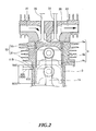
- Fig. 2 is a drawing showing the position of the crank chamber side opening 103.
- the piston 9 located at TDC is indicated by the solid line
- the piston 9 located at BDC is indicated by the broken line.
- the piston 9 includes a piston head 9a and a skirt part 9b following the piston head 9a.
- a termination portion 9c is formed at the end of the skirt part 9b in the crank chamber 7 side.
- the crank chamber side opening 103 of the communicating passage 104 in the crank chamber 7 side is formed to open in the position in the vicinity of termination portion 9c of the skirt part 9b of the piston 9 when the piston 9 is located at TDC. This prevents oil and so forth from entering the communicating passage 104 and the diaphragm chamber 110 due to a positive pressure created in the crank chamber 7 (crankcase 5).
- the crank chamber side opening 103 of the communicating passage 104 in the crank chamber 7 side is formed to open in the position closer to the crank axle 13a than the termination portion 9c when the piston 9 is located at TDC.
- crank chamber side opening 103 By forming the crank chamber side opening 103 in this position, it is possible to close the communicating passage 104 when a positive pressure is created in the crank chamber 7, and to consequently supply substantially only a negative pressure to the communicating passage 104. Then, at the time the negative pressure in the crank chamber is maximized (minimized), the crank chamber side opening 103 can open, and therefore it is possible to provide a pulsed negative pressure to the diaphragm chamber 110. By this means, it is possible to reliably drive the diaphragm fuel pump 109.
- An annular piston ring 52 is fitted into a portion of the side surface of the piston 9 in the combustion chamber 8 side.
- This piston ring 52 is formed by a compression ring 53 and an oil ring 51.
- the compression ring 53 needs to always be tightly attached to the cylinder part 3 because it is provided to separate the combustion chamber 8 from the crank chamber 7.
- the compression ring 53 needs to lubricate to prevent abrasion because it slidably moves. Therefore, there is much more oil in the gap portion between the cylinder part 3 and the piston 9 in the combustion chamber 8 side than in the region between the compression ring 53 and the oil ring 51.
- the communicating passage 104 may be located in the lower side of the engine body in working condition.
- a case is possible where the user leaves the working machine while the communicating passage 104 is located in the lower side.
- the present invention aims to prevent this problem by means of the check valve 115 described later, as an exemplary flowback prevention part.
- crank chamber side opening 103 is formed in the position apart from the oil ring 51 in the piston 9 when the piston 9 is located at BDC, it is required to increase the length of the skirt part 9b accordingly, and consequently to increase the size of the piston 9. Therefore, with the present embodiment, the crank chamber side opening 103 is formed in the vicinity of the oil ring 51 in the piston 9 when the piston 9 is located at BDC to reduce the size of the piston 9 and prevent oil from collecting in the crank chamber side opening 103.
- the atmospheric pressure opening passage 107 is essential for the present embodiment where the crank chamber side opening 103 is located in the vicinity of the termination portion 9c of the skirt part 9b of the piston 9 when the piston 9 is located at TDC. That is, the diaphragm fuel pump 109 cannot exhibit satisfactory performance without the atmospheric pressure opening passage 107 even if a negative pressure is applied to the communicating passage 104. It is because the crank chamber side opening 103 is closed by the skirt part 9b before the pressure returns to a positive pressure after the piston 9 has arrived at TDC and the pressure in the communicating passage 104 has been minimized. This causes a situation in which the pressure in the communicating passage 104 keeps a certain negative pressure, and therefore it is not possible to generate sufficient pressure fluctuation.
- the pressure can only change from the certain negative pressure to the minimum pressure.
- the diaphragm fuel pump 109 is driven depending on the magnitude of pressure fluctuation, and therefore cannot work if the magnitude of pressure fluctuation is small. Therefore, with the present embodiment, a configuration is adopted where the atmospheric pressure opening passage 107 is provided and the air is supplied to the communicating passage 104 while the crank chamber side opening 103 is closed by the skirt part 9b of the piston 9 to make the pressure fluctuation in the diaphragm chamber 110 greater.
- the period of time over which the crank chamber side opening 103 is closed is substantially longer than the period of time over which the crank chamber side opening 103 is open.
- the crank chamber side opening 103 does not need to be located in the vicinity of the termination portion 9c of the skirt part 9b of the piston 9 when the piston 9 is located at TDC.
- the crank chamber side opening 103 at the position shown in Fig. 2 , it is possible to apply a pulsed negative pressure to the diaphragm chamber 110 via the communicating passage 104.
- the reason why the crank chamber side opening 103 is provided at this position is that the crank chamber side opening 103 is covered with the skirt part 9b of the piston 9 until the piston 9 arrives at the vicinity of TDC even if a negative pressure is created in the crank chamber 7.
- Fig. 3 is a drawing showing the configuration of the check valve 115.
- the communicating passage 104 in a side member 55.
- This side member 55 allows the communicating passage 104 to be formed, and also allows the check valve 115 to be positioned at a predetermined position.
- various passages that allow, for example, oil, fuel, air and blowby gas to flow through may be formed in the side member 55.
- the side member 55 may function to hold the carburetor 25, the air cleaner 21 and so forth.
- the side member 55 may be formed integrally with the carburetor 25, the air cleaner 21 and so forth.
- the cylinder part 3 includes a first cylindrical space 116a, a second cylindrical space 116b and a third cylindrical space 116c to arrange them from the outer periphery to the center in this order as shown in Fig. 3 .
- the diameter of the first cylindrical space 116a is greater than that of the second cylindrical space 116b.
- the diameter of the second cylindrical space 116b is greater than that of the third cylindrical space 116c.
- the first cylindrical space 116a, the second cylindrical space 116b and the third cylindrical space 116c are formed concentrically.
- the check valve 115 includes a first elastic member 115a, a second elastic member 115b and a third elastic member 115c.
- the first elastic member 115a is a disc-like member having the central cavity.
- the first elastic member 115a is provided to fix the check valve 115 to a predetermined position.
- This first elastic member 115a is disposed in the first cylindrical space 116a.
- the second elastic member 115b is formed as a cylinder.
- This second elastic member 115b is disposed in the second cylindrical space 116b.
- the third elastic member 115c inclines upward and downward as shown in Fig. 3 .
- a check valve opening 115d is formed between the upper end and the lower end of the third elastic member 115c to be open in the horizontal direction. With this configuration, the check valve 115 allows fluid to move only in one direction from the diaphragm chamber 110 to the cylinder part 3.
- the first cylindrical space 116a is formed to accommodate the first elastic member 115a.
- the height of the first cylindrical space 116a is smaller than that of the first elastic member 115a. Therefore, the first elastic member 115a can be shrunk to be sandwiched between the outer wall of the side member 55 in the cylinder part 3 side and the inner wall of the first cylindrical space 116a of the cylinder part 3. As a result, the check valve 115 can be positioned and fixed onto a predetermined position.
- the check valve 115 is disposed in the cylinder part 3, and therefore needs to have heat resistance. Moreover, the check valve 115 also needs to have oil resistance because there is oil in the cylinder part 3.
- the third elastic member 115c due to the structure of the check valve, at least part of the member constituting the check value 115, to be more specific, the third elastic member 115c, needs to have elasticity.
- the structure of the check valve 115 is not limited to this. A poppet valve, a swing valve, a wafer valve, a lift valve, a ball valve and a foot valve are possible.
- the side member 55 is attached to the cylinder part 3 with a bolt member 125.
- a bolt member 125 is not limited to a bolt as long as the side member 55 can be positioned and fixed onto a predetermined position of the cylinder part 3.
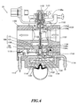
- Fig. 4 is a drawing showing the configuration of the carburetor 25 to which the diaphragm fuel pump 109 is applied.
- the carburetor 25 includes a carburetor body 1102.
- the communicating passage 104 which allows communication with the crank chamber 7, is formed in the carburetor body 1102.
- This communicating passage 104 faces the diaphragm chamber 110, which is one side (the upper part in the figure) of the diaphragm fuel pump 109.
- a pump chamber 1108 is formed in the other side (the lower part in the figure) of the diaphragm fuel pump 109.
- a fuel inlet 1112 communicates with the pump chamber 1108 via an inlet valve 1110, and a metering chamber 1118 in a metering diaphragm 1120 communicates with the pump chamber 1108 via an outlet valve 1114 and a needle valve 1116.
- the fuel inlet 1112 is connected to a fuel tank (not shown) .
- the crank chamber side opening 103 of the communicating passage 104 in the crank chamber 7 side is formed in the cylinder part 3 which defines the crank chamber 7.
- the pressure in the crank chamber 7 varies according to a change in its volume. As described above, only a negative pressure of the varying pressure affects the diaphragm chamber 110 via the communicating passage 104. Then, the diaphragm fuel pump 109 is driven by the negative pressure affecting the diaphragm chamber 110. To be more specific, a negative pressure affects the diaphragm chamber 110 in the diaphragm fuel pump 109, and therefore the negative pressure affects the pump chamber 1108 side when the diaphragm 108 bends to the diaphragm chamber 110 side. The negative pressure in the pump chamber 1108 allows the inlet valve 1110 to open while the outlet valve 1114 is closed, and therefore fuel is sucked from the fuel inlet 1112 into the pump chamber 1108.
- the metering chamber 1118 is separated from a back pressure chamber 1122 by the metering diaphragm 1120.
- the pressure of the four-stroke engine 1 affects the back pressure chamber 1122.
- the metering diaphragm 1120 is driven by the difference in pressure between the four-stroke engine 1 and the metering chamber 1118.
- a passage is not shown in the figure, which allows communication between the back pressure chamber 1122 and the space under a negative pressure in the engine.
- the metering diaphragm 1120 is connected to the above-described needle valve 1116 via a control lever 1124, and operates to open and close the needle valve 1116.
- the pressure in the metering chamber 1118 rises and the metering diaphragm 1120 bends to the back pressure chamber 1122 side.
- the elastic force of a control lever spring 1126 causes the control lever 1124 to rotate such that one end (the left side in the figure) of the control lever 1124 is pushed down and the other end (the right side in the figure) is pushed up.
- This rotation of the control lever 1124 causes the needle valve 1116 to push up and breaks the communication between the pump chamber 1108 and the metering chamber 1118.
- a passage 1128 is formed in the carburetor body 1102 to connect between the intake port 27 formed in the cylinder part 3 and the air cleaner 21.
- This passage 1128 has a large diameter part 1128a in the upper stream side (the air cleaner 21 side) and a smaller venturi part 1128b in the downstream side (the intake port 27 side) than the large diameter part 1128a.
- the venturi part 1128b includes a throttle valve 1130 to change its opening.
- the axis of rotation of the throttle valve 1130 is orthogonal to the passage 1128.
- this throttle valve 1130 is provided with a first adjuster screw 1131 which is coaxial with the axis of the rotation of the throttle valve 1130 to fine-tune the amount of fuel mixed into the air flowing through the passage 1128.
- This first adjuster screw 1131 is provided with a second adjuster screw 1132 which is coaxial with the axis of rotation of the first adjuster screw 1131.
- the second adjuster screw 1132 is provided to extend upward and downward in the figure.
- the outer diameter of the second adjuster screw 1132 which is approximately the same as the inner diameter of the nozzle 1134 described later, reduces from the top to the bottom in two steps.
- a switching part 1132a to switch a main jet 1136 described later is provided on the tip of the second adjuster screw 1132.
- the first adjuster screw 1131 moves downward, rotating in one direction (to tighten the screw) with respect to the throttle valve 1130, and, on the other hand, moves upward, rotating in the other direction (to loosen the screw) with respect to the throttle valve 1130.
- the second adjuster screw 1132 moves downward, rotating in one direction (to tighten the screw) with respect to the first adjuster screw 1131, and, on the other hand, moves upward, rotating in the other direction (to loosen the screw) with respect to the first adjuster screw 1131.
- the nozzle 1134 is provided in the carburetor body 1102 to face the second adjuster screw 1132.
- the tip of the second adjuster screw 1132 is inserted into a nozzle tip 1134a of the nozzle 1134.
- the nozzle 1134 includes a hole 1134b which is open in the passage 1128.
- a bottom 1134c in communication with the hole 1134b faces the metering chamber 1118.
- the main jet 1136 and a main check valve 1138 which serve as a mixture ratio adjusting means and fuel adjusting mechanism, are provided between the hole 1134b and the metering chamber 1118.
- Fig. 5 is a drawing showing the nozzle 1134.
- Fig. 6 is a cross sectional view of Fig. 5 taken along line A-A' of Fig. 5 .
- the main jet 1136 includes a first main jet part 113 6a and a second main jet part 113 6b.
- the first main jet part 1136a has a predetermined opening area to allow communication between the hole 1134b of the nozzle 1134 and the metering chamber 1118.
- the second main jet part 1136b has a lager opening area than of the first main jet part 1136a to allow communication between the hole 1134b of the nozzle 1134 and the metering chamber 1118.
- One of the first main jet part 1136a and the second main jet part 1136b of the main jet 1136 is closed by the switching part 1132a in the second adjuster screw 1132, and the other allows communication between the hole 1134b of the nozzle 1134 and the metering chamber 1118.
- By rotating the second adjuster screw 1132 with respect to the first adjuster screw 1131 it is possible to switch between open and close of the first main jet part 1136a and the second main jet part 1136b of the main jet 1136. That is, by rotating the second adjuster screw 1132 with respect to the first adjuster screw 1131 according to fuel to be used, it is possible to deliver fuel to one of the first main jet part 113 6a and the second main jet part 1136b of the main jet 1136.
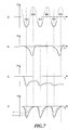
- Fig. 7 is a drawing showing an effect of the present embodiment.
- the crank chamber side opening 103 of the communicating passage 104 in the crank chamber 7 side is formed to open in the position near the position in which the termination portion 9c of the skirt part 9b of the piston 9 is located when the piston 9 is located at TDC.
- the pressure in the crank chamber 7 acts near the crank chamber side opening 103 as shown in the solid line in Fig. 7A .
- the pressure in the communicating passage 104 can only fluctuate as shown in Fig. 7C .
- the atmospheric pressure opening passage 107 is connected to the communicating passage 104 to allow the air in the space under atmospheric pressure to be supplied to the communicating passage 104.
- the pressure in the communicating passage 104 is returned to nearly atmospheric pressure, so that it is possible to make pressure fluctuation greater as shown in Fig. 7D .
- broken line a shown in Fig. 7D shows the pressure fluctuation in a case in which the air cleaner side orifice 111 is not provided in the air cleaner side opening 117 of the atmospheric pressure opening passage 107.
- solid line b shown in Fig. 7D shows the pressure fluctuation in a case in which the air cleaner side orifice 111 is provided in the air cleaner side opening 117 of the atmospheric pressure opening passage 107.
- the air cleaner side orifice 111 is not always required, but a case is possible where the pipeline is thinned, lengthened, bent and the like to control pipeline resistance. However, with the above-described methods, it is not easy to control pipeline resistance. Therefore, it is preferable to provide the air cleaner side orifice 111.
- the atmospheric pressure opening passage 107 By providing the atmospheric pressure opening passage 107, it is possible to discharge oil and so forth having entered the communicating passage 104. Here, for this, it is preferable to increase a speed at which the air flows from the atmospheric pressure opening passage 107 to the communicating passage 104.
- Fig. 8 is a schematic view showing the four-stroke engine according to Embodiment 2 of the present invention.
- Fig. 9 is a drawing to give a detailed description of the four-stroke engine according to Embodiment 2.
- the atmospheric pressure opening passage 107 does not communicate with the communicating passage 104 but communicates with the diaphragm chamber 110 in the diaphragm fuel pump 109.
- the atmospheric pressure opening passage 107 is formed in the carburetor 25. This atmospheric pressure opening passage 107 is connected to the air cleaner 21 side, and therefore easily communicates with the air cleaner 21.
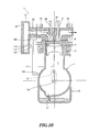
- Fig. 10 is a schematic view showing the four-stroke engine according to Embodiment 3 of the present invention.
- the communicating passage 104 is open in the cylinder part 3 or the crankcase 5.
- the location where the communicating passage 104 is open is not limited.
- the communicating passage 104 may be open, for example, in the intake port 27 as long as the communicating passage 104 is formed in a place in which a negative pressure is applied.
- the communicating passage 104 may be open in any negative pressure part in the four-stroke engine 1.
- Fig. 11 is a schematic view showing the four-stroke engine according to Embodiment 5 of the present invention.
- Fig. 11 shows the four-stroke engine 1 in a state in which the piston 9 is located in the vicinity of TDC.
- the four-stroke engine 1 includes the cylinder part 3, the crankcase 5 mounted under the cylinder part 3 and the oil tank 15 provided below the crankcase 5.
- the cylinder part 3 has the cylindrical space to slidably move the piston 9 upward and downward in Fig. 11 .
- the piston 9 is fitted into the space with a gap to slidably move upward and downward in Fig. 11 .
- the crank chamber 7 is defined by the cylinder part 3, the crankcase 5 and the piston 9. That is, the crank chamber 7 is an approximately cylindrical space defined by the side surface of the cylinder part 3, the piston 9 and the crankcase 5.
- the volume of the inner space of this crank chamber 7 varies as the piston 9 slidably moves.
- the combustion chamber 8 is defined by the cylinder head 26, the cylinder part 3 and the piston 9.
- the oil tank 15 to store oil is provided separately from the crankcase 5.
- a crank chamber crank chamber check valve 17 is provided between the oil tank 15 and the crankcase 5 to allow oil to flow only in the direction from the crankcase 5 (crank chamber 7) to the oil tank 15.
- a negative pressure is created in the crank chamber 7 as the piston 9 moves from the bottom dead center (BDC) to TDC.
- BDC bottom dead center
- a positive pressure is created in the crank chamber 7 as the piston 9 moves from TDC to BDC.
- a negative pressure is easily created in the crank chamber 7 because the crank chamber check valve 17 is provided, the pressure in the crank chamber 7 can rise only up to a positive pressure that overcomes the elasticity of a spring and so forth used in the crank chamber check valve 17.
- crank chamber 7 is a negative pressure part because a negative pressure is created in the crank chamber 7 when the piston 9 moves from BDC to TDC.
- the pressure in the crank chamber 7 changes once while the crank axle 13a rotates once. This is different from the pressure in an intake port or an exhaust port, which changes only once while the crank axle 13a rotates twice.
- the crank 13 is rotatably supported in the crankcase 5. This crank 13 is formed by the crank axle 13a which is the center of rotation, counterweight and so forth.
- the piston 9 and the crank 13 are connected one another via the connecting rod 11.
- the connecting rod 11 is rotatably connected to both the piston 9 and the crank 13. This configuration allows the piston 9 to reciprocally and slidably move in the cylinder part 3.
- the cylinder head 26 is provided on the upper wall of the cylinder part 3.
- the cylinder head 26 is provided with the intake port 27 that allows communication with the carburetor 25 and the exhaust port 33 that allows communication with the exhaust muffler (not shown).
- the cylinder head 26 is also provided with the intake valve 29 to open and close the intake port 27.
- the cylinder head 26 is provided with the exhaust valve 31 to open and close the exhaust port 33.
- a negative pressure is created in the intake port every time the intake valve 29 opens and closes. Therefore, also the intake port 27 is a negative pressure part.
- the crank chamber 7 may be a negative pressure part.
- the four-stroke engine 1 also has a positive pressure part 4 such as the exhaust port 33 in which a positive pressure is created every time the exhaust valve 31 opens and closes. Then, the negative pressure part, the positive pressure part, and part in which both a positive pressure and a negative pressure are created alternatively, are collectively referred to as a pressure fluctuation part.
- the air cleaner 21 is provided outside the carburetor 25.
- the filter 23 is disposed in the air cleaner 21. The filter 23 allows air to pass through to remove dust and so forth in the air.
- the carburetor 25 is an apparatus to mix fuel into the air having passed through the air cleaner 21. To be more specific, the carburetor 25 can control mixing of the air and fuel and also control the total amount of the air-fuel mixture.
- the carburetor 25 has the diaphragm fuel pump 109 to mix fuel into the air. This diaphragm fuel pump 109 is driven using pressure fluctuation as power.
- the diaphragm chamber 110 in the diaphragm fuel pump 109 is connected to a pressure applying part 114 via the communicating passage 104 to supply power.
- the pressure applying part 114 is open from the crank chamber opening 103 into the crank chamber 7.
- the diaphragm fuel pump 109 is provided with a diaphragm 108 whose position changes in response to pressure fluctuation.
- the communicating passage 104 is open in the cylinder part 3, it is by no means limiting but the communicating passage 104 may be open in a negative pressure part.
- the communicating passage 104 is open in the cylinder part 3 via the pressure applying part 114, it is advantageous to supply a pulsed negative pressure to the diaphragm fuel pump 109. This will be described later.
- Fig. 12 is a drawing showing the crank chamber side opening 103.
- the piston 9 located at TDC is indicated by the solid line
- the piston 9 located at BDC is indicated by the broken line.
- the pressure applying part 114 includes an elastic film 127, a first chamber 131 and a second chamber 129.
- the first chamber 131 is open into the cylinder part 3 via the crank chamber side opening 103.
- the second chamber 129 is connected directly to the communicating passage 104. Therefore, the second chamber 129 communicates with the diaphragm chamber 110 (see Fig. 11 ). By this means, the pressure in the second chamber 129 is transmitted as is.
- the elastic film 127 is formed not to allow fluid to flow through and can vibrate not a little, like the diaphragm 108 (see Fig. 14 ) of the diaphragm fuel pump 109.
- the elastic film 127 may be made of an elastic member such as rubber.
- the elastic film 127 may be a metal film or a plastic film having a bellows structure.
- the piston 9 includes the piston head 9a and the skirt part 9b following the piston head 9a.
- the termination portion 9c is formed at the end of the skirt part 9b in the crank chamber 7 side.
- the crank chamber side opening 103 of the communicating passage 104 in the crank chamber 7 side is formed to open in the position in the vicinity of termination portion 9c of the skirt part 9b of the piston 9 when the piston 9 is located at TDC.
- the crank chamber side opening 103 of the communicating passage 104 in the crank chamber 7 side is formed to open in the position closer to the crank axle 13a than the termination portion 9c when the piston 9 is located at TDC.
- the crank chamber side opening 103 can open, and therefore it is possible to provide a pulsed negative pressure to the diaphragm chamber 110.
- the annular piston ring 52 is fitted into a portion of the side surface of the piston 9 in the combustion chamber 8 side.
- This piston ring 52 is formed by the compression ring 53 and the oil ring 51.
- the compression ring 53 needs to always be tightly attached to the cylinder part 3 because it is provided to separate the combustion chamber 8 from the crank chamber 7.
- the compression ring 53 needs to lubricate to prevent abrasion because it slidably moves. Therefore, there is much more oil in the gap portion between the cylinder part 3 and the piston 9 in the combustion chamber 8 side than in the region between the compression ring 53 and the oil ring 51.
- the communicating passage 104 may be located in the lower side of the engine body in working condition.
- a case is possible where the user leaves the working machine while the communicating passage 104 is located in the lower side.
- the present invention aims to prevent this problem by means of the elastic film 127, as an exemplary flowback prevention part.
- crank chamber side opening 103 is formed in the position apart from the position in which the oil ring 51 in the piston 9 is located when the piston 9 is located at BDC, it is required to increase the length of the skirt part 9b accordingly, and consequently increase the size of the piston 9. Therefore, with the present embodiment, the crank chamber side opening 103 is formed the vicinity of the oil ring 51 in the piston 9 when the piston 9 is located at BDC to reduce the size of the piston 9 and prevent oil from collecting in the crank chamber side opening 103.
- crank chamber side opening 103 does not need to be located in the vicinity of the termination portion 9c of the skirt part 9b of the piston 9 when the piston 9 arrives at TDC.
- the crank chamber side opening 103 by providing the crank chamber side opening 103 at the position shown in Fig. 12 , it is possible to apply a pulsed negative pressure to the diaphragm chamber 110 via the communicating passage 104.
- the reason why the crank chamber side opening 103 is provided at this position is that the crank chamber side opening 103 is covered with the skirt part 9b of the piston 9 until the piston 9 arrives at the vicinity of TDC even if a negative pressure is created in the crank chamber 7.
- the communicating passage 104 is filled with fluid.
- the communicating passage 104 is filled with air, it is by no means limiting.
- the communicating passage 104 may be filled with nitrogen gas and so forth.
- the communicating passage 104 may be filled with liquid such as oil.
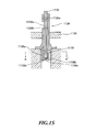
- Fig. 13 is a drawing showing the configuration of the pressure applying part 114.
- the communicating passage 104 in the side member 55.
- This side member 55 allows the communicating passage 104 to be formed, and also allows the elastic film 127 in the pressure applying part 114 to be positioned and fixed onto a predetermined position.
- various passages that allow, for example, oil, fuel, air and blowby gas to flow through may be formed in the side member 55.
- the side member 55 may function to hold the carburetor 25, the air cleaner 21 and so forth.
- the side member 55 may be formed integrally with the carburetor 25, the air cleaner 21 and so forth.
- the first chamber 131 is formed in the cylinder part 3.
- This first chamber 131 is constituted by a plurality of cavity portions 116.
- the cylinder part 3 includes the first cylindrical space 116a, the second cylindrical space 116b and the third cylindrical space 116c to arrange them from the outer periphery to the center in this order as shown in Fig. 13 .
- the diameter of the first cylindrical space 116a is greater than that of the second cylindrical space 116b.
- the diameter of the second cylindrical space 116b is greater than that of the third cylindrical space 116c.
- the diameter of the third cylindrical space 116c is greater than that of the fourth cylindrical space 116d.
- the first cylindrical space 116a, the second cylindrical space 116b, the third cylindrical space 116c, and the fourth cylindrical space 116d are formed concentrically.
- the second chamber 129 is formed in the side member 55.
- the cross section of the cylindrical second chamber 129 is the same as that of the first cylindrical space 116a.
- the elastic film 127 is disposed between the first chamber 31 and the second chamber 129. This elastic film 127 is sandwiched and held between the side surface of the side member 55 in the cylinder part 3 side and the outer surface of the cylinder part 3.
- a cylindrical hollow may be provided to hold the elastic film 127 such that the outer rim of the elastic film 127 is fit into the cylindrical hollow.
- the elastic film 127 includes a bias member 143 to bias the elastic film 127 to the side member 55 side (second chamber 129 side).
- This bias member 143 includes an elastic member 133 (helical spring) and an elastic member holding part 141.
- the elastic member holding part 141 includes a first holding part 135 and a second holding part 137.
- the first holding part 135 is formed as a low column.
- the second holding part 137 is formed as a cylinder having a cylindrical hollow space 139 therein.
- the first holding part 135 is connected to the elastic film 127 with adhesive.
- the elastic member 133 having the same outer periphery as the inner periphery of the inner space 139 is inserted in the inner space 139. By this means, the elastic member 133 is held.
- One end of the elastic member 133 which is opposite to the end inserted in the inner space 139, is inserted in the third cylindrical space 116c. Then, the end of the elastic member 133, which is opposite to the end inserted in the inner space 139, contacts the end of the third cylindrical space 116c in the fourth cylindrical space 116 side. In this state, the elastic member 133 is shrunk.
- the pressure applying part 114 is disposed in the cylinder part 3, and therefore needs to have heat resistance. Moreover, the pressure applying part 114 also needs to have oil resistance because there is oil in the cylinder part 3. Particularly, the elastic film 127 needs to be made of rubber and so forth having elasticity. If not so, the elastic film 127 would not have satisfactory oil resistance, in particular, heat resistance. Therefore, the elastic film 127 must be made of a material having oil resistance, in particular, heat resistance.
- the side member 55 is attached to the cylinder part 3 with a bolt member 125.
- a bolt member 125 By this means, it is possible to readily position and fix the side member 55 onto a predetermined position of the cylinder part 3. As a result, it is possible to readily position and fix the pressure applying part 114 (particularly elastic film 127). As a result, the four-stroke engine 1 can be more simply assembled. In addition, it is possible to reduce the number of parts.
- the bolt member 125 is not limited to a bolt as long as the side member 55 can be positioned and fixed onto a predetermined position of the cylinder part 3.
- the elastic film 127 is biased to the second chamber 129, so that it is possible to apply only negative pressure to the diaphragm chamber 110.
- Fig. 14 is a drawing showing the configuration of the carburetor 25 to which a diaphragm fuel pump 109 is applied.
- the carburetor 25 includes the carburetor body 1102.
- the communicating passage 104 which allows communication with the crank chamber 7, is formed in the carburetor body 1102.
- This communicating passage 104 faces the diaphragm chamber 110, which is one side (the upper part in the figure) of the diaphragm fuel pump 109.
- the pump chamber 1108 is formed in the other side (the lower part in the figure) of the diaphragm fuel pump 109.
- the fuel inlet 1112 communicates with the pump chamber 1108 via the inlet valve 1110, and the metering chamber 118 in the metering diaphragm 1120 communicates with the pump chamber 1108 via the outlet valve 1114 and the needle valve 1116.
- the fuel inlet 1112 is connected to the fuel tank (not shown).
- the crank chamber side opening 103 of the communicating passage 104 in the crank chamber 7 side is formed in the cylinder part 3 which defines the crank chamber 7.
- the pressure in the crank chamber 7 varies according to a change in its volume. As described above, only a negative pressure of the varying pressure affects the diaphragm chamber 110 via the communicating passage 104. Then, the diaphragm fuel pump 109 is driven by the negative pressure affecting the diaphragm chamber 110. To be more specific, a negative pressure affects the diaphragm chamber 110 in the diaphragm fuel pump 109, and therefore the negative pressure affects the pump chamber 1108 side when the diaphragm 108 bends to the diaphragm chamber 110 side. The negative pressure in the pump chamber 1108 allows the inlet valve 1110 to open while the outlet valve 1114 is closed, and therefore fuel is sucked from the fuel inlet 1112 into the pump chamber 1108.
- the metering chamber 1118 is separated from a back pressure chamber 1122 by the metering diaphragm 1120.
- the pressure of the four-stroke engine 1 affects the back pressure chamber 1122.
- the metering diaphragm 1120 is driven by the difference in pressure between the four-stroke engine 1 and the metering chamber 1118.
- a passage is not shown in the figure, which allows communication between the back pressure chamber 1122 and the space under a negative pressure in the engine.
- the metering diaphragm 1120 is connected to the above-described needle valve 1116 via the control lever 1124, and operates to open and close the needle valve 1116.
- the pressure in the metering chamber 1118 rises and the metering diaphragm 1120 bends to the back pressure chamber 1122 side.
- the elastic force of the control lever spring 1126 causes the control lever 1124 to rotate such that one end (the left side in the figure) of the control lever 1124 is pushed down and the other end (the right side in the figure) is pushed up.
- This rotation of the control lever 1124 causes the needle valve 1116 to push up and breaks the communication between the pump chamber 1108 and the metering chamber 1118.
- the passage 1128 is formed in the carburetor body 1102 to connect between the intake port 27 formed in the cylinder part 3 and the air cleaner 21.
- This passage 1128 has the large diameter part 1128a in the upper stream side (the air cleaner 21 side) and the smaller venturi part 1128b in the downstream side (the intake port 27 side) than the large diameter part 1128a.
- the venturi part 1128b includes the throttle valve 1130 to change its opening.
- the axis of rotation of the throttle valve 1130 is orthogonal to the passage 1128.
- this throttle valve 1130 is provided with the first adjuster screw 1131 which is coaxial with the axis of rotation of the throttle valve 1130 to fine-tune the amount of fuel mixed into the air flowing through the passage 1128.
- This first adjuster screw 1131 is provided with the second adjuster screw 1132 which is coaxial with the axis of rotation of the first adjuster screw 1131.
- the second adjuster screw 1132 is provided to extend upward and downward in the figure.
- the outer diameter of the second adjuster screw 1132 which is approximately the same as the inner diameter of the nozzle 1134 described later, reduces from the top to the bottom in two steps.
- the switching part 1132a to switch a main jet 1136 described later is provided on the tip of the second adjuster screw 1132.
- the first adjuster screw 1131 moves downward, rotating in one direction (to tighten the screw) with respect to the throttle valve 1130, and, on the other hand, moves upward, rotating in the other direction (to loosen the screw) with respect to the throttle valve 1130.
- the second adjuster screw 1132 moves downward, rotating in one direction (to tighten the screw) with respect to the first adjuster screw 1131, and, on the other hand, moves upward, rotating in the other direction (to loosen the screw) with respect to the first adjuster screw 1131.
- the nozzle 1134 is provided in the carburetor body 1102 to face the second adjuster screw 1132.
- the tip of the second adjuster screw 1132 is inserted into the nozzle tip 1134a of the nozzle 1134.
- the nozzle 1134 includes a hole 1134b which is open in the passage 1128.
- a bottom 1134c in communication with the hole 1134b faces the metering chamber 1118.
- the main jet 113 and a main check valve 1138 which serve as a mixture ratio adjusting means and fuel adjusting mechanism, are provided between the hole 1134b and the metering chamber 1118.
- Fig. 15 is a drawing showing the nozzle 1134.
- Fig. 16 is a cross sectional view of Fig. 15 taken along line A-A.
- the main jet 113 includes the first main jet part 113 6a and the second main jet part 1136b.
- the first main jet part 1136a has a predetermined opening area to allow communication between the hole 1134b of the nozzle 1134 and the metering chamber 1118.
- the second main jet part 1136b has a lager opening area than of the first main jet part 1136a to allow communication between the hole 1134b of the nozzle 1134 and the metering chamber 1118.
- One of the first main jet part 1136a and the second main jet part 1136b of the main jet 1136 is closed by the switching part 1132a in the second adjuster screw 1132, and the other allows communication between the hole 1134b of the nozzle 1134 and the metering chamber 1118.
- By rotating the second adjuster screw 1132 with respect to the first adjuster screw 1131 it is possible to switch between open and close of the first main jet part 113 6a and the second main jet part 113 6b of the main jet 1136. That is, by rotating the second adjuster screw 1132 with respect to the first adjuster screw 1131 according to fuel to be used, it is possible to deliver fuel to one of the first main jet part 1136a and the second main jet part 1136b of the main jet 1136.
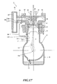
- Fig. 17 is a schematic view showing the four-stroke engine according to Embodiment 6 of the present invention.
- the cross section of the pressure applying part 114 including the elastic film 127 is referred to as a first cross section S1
- the cross section of the diaphragm chamber 110 in the diaphragm fuel pump 109 is referred to as a second cross section S2.
- the cross-section of the diaphragm chamber 110 in the diaphragm fuel pump 109 is orthogonal to the normal of the diaphragm 108.
- the cross section of the pressure applying part 114 is orthogonal to the normal of the elastic film 127.
- a configuration is possible to prevent oil from entering the communicating passage 104 and also to use both a negative pressure and a positive pressure, and therefore to prevent the parts that communicate with the elastic film 127, from being limited to a specific part (for example, the crank chamber 7).
- a specific part for example, the crank chamber 7
- Fig. 18 is a schematic view showing the four-stroke engine according to Embodiment 7 of the present invention.
- the crankcase 5 may communicate with the elastic film 127 instead of the cylinder part 3. It is because, with the present invention, both negative pressure and positive pressure can be used, the parts that communicate with the elastic film 127 are not limited to a specific part (for example, the cylinder part 3). In addition, with the present invention, oil does not enter the communicating passage 104, and therefore it is possible to provide a part that communicates with the elastic film 127 in the crankcase 5 in which a positive pressure may be created.
- Fig. 19 is a schematic view showing the four-stroke engine according to Embodiment 8 of the present invention.
- the communicating passage 104 allows liquid such as oil, water and so forth to flow through. In this case, it is possible to more reliably apply the pressure from the pressure applying part 114 to the diaphragm chamber 110.
- Fig. 19 shows a configuration in which a negative pressure is used, and this configuration is advantageous to the diaphragm fuel pump 109 using a positive pressure. Here, negative pressure is effectively used within a range of atmosphere pressure.
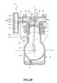
- Fig. 20 is a schematic view showing the four-stroke engine according to Embodiment 9 of the present invention.
- the communicating passage 104 has a sealed structure.
- the four-stroke engine 1 generates a large amount of heat while driving.
- the communicating passage 104 is highly likely to be located in the vicinity of the combustion chamber 8. Particularly, as shown in Fig. 13 , when the side member 55 in which the communicating passage 104 is formed contacts the cylinder part 3, the communicating passage 104 tends to be heated.
- the temperature of the inside of the communicating passage 104 increases independent of the heat of the combustion chamber 8. If the temperature of the communicating passage 104 increases, the elastic film 127 shown in Fig. 13 always contacts the first chamber 131.
- the pressure applying part 114 cannot transmit pressure fluctuation to the diaphragm fuel pump 109.
- the same case is likely to occur in an area at a high altitude and a low pressure.
- the atmospheric pressure opening passage 107 as shown in Fig. 20 is provided.
- This atmospheric pressure opening passage 107 has the air cleaner side opening 117 in the air cleaner 21.
- This atmospheric pressure opening passage 107 communicates with the atmospheric pressure side with an aperture area that rarely allows gas to enter and exit the communicating passage 104 when the diaphragm 108 moves. In this way, by providing the air cleaner side opening 117, the degree of the pressure fluctuation applied to the diaphragm chamber 110 is reduced.
- the communicating passage 104 may communicate with the atmospheric pressure side with an aperture area that rarely allows gas to enter and exit the communicating passage 104.
- the atmospheric pressure opening passage 107 is open in the air cleaner 21.
- the atmospheric pressure opening passage 107 is not necessarily be open in the air cleaner 21 because it is sufficient for the atmospheric pressure opening passage 107 to communicate with the atmospheric pressure side.
- the atmospheric pressure opening passage 107 is open in the air cleaner 21, conveniently, it is possible to prevent dust, water and so forth from entering the communication passage 104.
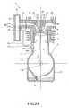
- Fig. 21 is a schematic view showing the four-stroke engine according to Embodiment 10 of the present invention.
- the atmospheric opening passage 107 is formed in the carburetor 25, and therefore it is possible to provide an advantage of easy fabrication.
- the four-stroke engine 1 includes the piston 9 and the carburetor 25; the carburetor 25 includes the diaphragm fuel pump 109; the diaphragm fuel pump 109 includes the pump chamber 1108 that sucks and discharges fuel, a diaphragm chamber 110 to which the pressure to drive the pump chamber 1108 is applied, and the communicating passage 104 that connects between the negative pressure part in which a negative pressure is created due to the movement of the piston 9 and the diaphragm chamber 110.
- the flowback prevention part (check valve 115) is provided in the communicating passage 104 to allow fluid to move only in one direction from the diaphragm chamber 110 side to the negative pressure part (in the cylinder part 3).
- the negative pressure part (in the cylinder part 3) may be the crank chamber 7 through which the piston 9 slidably moves.
- the flowback prevention part (check valve 115) is formed in the crank chamber side opening 103 of the cylinder part 3.
- the communicating passage 104 is formed in the side member 55 contacting the cylinder part 3.
- the side member 55 positions and fixes the flowback prevention part (check valve 115) in the cylinder part 3. With this configuration, the four-stroke engine 1 can be more simply assembled.
- the atmospheric pressure opening passage 107 that communicates with the space under atmospheric pressure is connected to the communicating passage 104. With this configuration, it is possible to continuously drive the diaphragm fuel pump 109.
- the atmospheric pressure opening passage 107 that communicates with the atmospheric pressure side is connected to the diaphragm chamber 110. With this configuration, it is possible to easily form the atmospheric pressure opening passage 107 by providing a passage that penetrates the carburetor 25.
- the atmospheric pressure opening passage 107 is formed in the carburetor 25 and is open in the air filter 21. With this configuration, it is possible to prevent dust and so forth from entering the diaphragm fuel pump 109. Moreover, it is possible to prevent dust and so forth from entering the cylinder part 3.
- crank chamber side opening 103 of the communicating passage 104 in the crank chamber 7 side is formed to open in the position in the vicinity of the termination portion 9c of the skirt part 9b of the piston 9 when the piston 9 is located at TDC.
- crank chamber side opening 103 of the communicating passage 104 in the crank chamber 7 side is formed to open in the position closer to the crank axle 13a than the piston ring 52 when the piston 9 is located at TDC.
- crank chamber side opening 103 of the communicating passage 104 in the crank chamber 7 side is formed in the vicinity of the piston ring 52 of the piston 9 when the piston 9 is located at BDC. With this configuration, it is possible to reduce the size of the piston 9 and prevent oil from collecting in the crank chamber side opening 103.
- the orifice (air cleaner side orifice 111) is formed in the atmospheric pressure opening passage 107 that is connected to the communicating passage 104 or the diaphragm chamber 110 to communicate with the space under atmospheric pressure.
- the four-stroke engine 1 includes the piston 9, the carburetor 25, the elastic film 127, the first chamber 131 formed on one side of the elastic film 127 and the second chamber 129 formed on the other side of the elastic film 127.
- the carburetor 25 includes the diaphragm fuel pump 109.
- the diaphragm fuel pump 109 includes the diaphragm chamber 110 to which a pressure to drive the pump chamber 1108 is applied, and the pump chamber 1108 that sucks and discharges fuel.
- the first chamber 131 communicates with the pressure fluctuation part (e.g. cylinder part 3) in which there is pressure fluctuation due to the movement of the piston 9.
- the second chamber 129 communicates with the diaphragm chamber 110.
- the pressure fluctuation part communicates with the negative pressure part (e.g. cylinder part 3) in which a negative pressure is created due to the movement of the piston 9, and has the bias member (e.g. helical spring) that biases the elastic film 127 to the second chamber 129 side.
- the bias member e.g. helical spring
- the second chamber 129 is formed to communicate with the cylinder part 3 in the vicinity of the termination portion 9c of the skirt part 9b of the piston 9 when the piston 9 is located at TDC.
- the second chamber 129 is formed to communicate with the cylinder part 3 in the position closer to the crank axle 13a than the piston ring 52 when the piston 9 is located at BDC. With this configuration, it is possible to prevent oil from adhering to the crank chamber side opening 103.
- the second chamber 129 is formed in the vicinity of the piston ring 52 of the piston 9 when the piston 9 is located at BDC. With this configuration, it is possible to reduce the size of the piston 9 and prevent oil from collecting in the crank chamber side opening 103.
- the four-stroke engine 1 includes the side member 55 disposed on the side surface of the cylinder part 3.
- the communicating passage 104 that allows communication between the second chamber 129 and the diaphragm chamber 110 is formed in the side member 55.
- the elastic film 127 is sandwiched between the side member 55 and the cylinder part 3, and therefore is positioned and fixed onto a predetermined position. With this configuration, it is possible to readily assemble the four-stroke engine 1 having the elastic film 127. In addition, it is possible to reduce the number of parts.
- the first cross section S1 is defined in the first chamber 131 and the second chamber 129 in the direction in which the elastic film 127 is formed.
- the second cross section S2, which is different from the first cross section S1 is defined in the pump chamber 1108 and the diaphragm chamber 110 in the direction in which the diaphragm 108 is formed.
- the second cross section S2 is greater than the first cross section S1.
- the four-stroke engine 1 includes the communicating passage 104 that allows communication between the second chamber 129 and the diaphragm chamber 110.
- This communicating passage 104 communicates with the atmospheric pressure side with an aperture area that rarely allows gas to enter and exit the communicating passage 104 when the diaphragm 108 moves. With this configuration, it is possible to reliably drive the diaphragm fuel pump 109 under an environment at a high temperature and a low pressure.
- the communicating passage 104 is filled with liquid. With this configuration, it is possible to reliably apply the pressure in the pressure applying part 114 to the diaphragm chamber 110.
- the negative pressure part according to the present invention is not limited as long as the pressure in the negative pressure part becomes lower than atmospheric pressure regularly.
- the negative pressure part may be the cylinder part 3 or the crankcase 5 in the crank chamber 7, or the intake port 27.
- the check valve 115 is an exemplary flowback prevention part according to the present invention.
- the flowback prevention part according to the present invention is not limited as long as it allows fluid to move only in one direction.
- the pressure fluctuation part is not limited as long as the pressure in the pressure fluctuation part fluctuates regularly.
- the negative pressure part is an exemplary pressure fluctuation part according to the present invention.
- the pressure fluctuation part according to the present invention may be a part in which the pressure changes to a positive pressure.
- the pressure fluctuation part may be the exhaust port 33.
- the negative pressure part according to the present invention is not limited as long as the pressure in the negative pressure part changes from a certain pressure to a negative pressure regularly.
- the negative pressure part may be the cylinder part 3 or the crankcase 5 in the crank chamber 7, or the intake port 27.
- each of the plurality of hollow parts is formed as a cylinder.
- a configuration has been explained where the cylinder head 26 is formed separately from the cylinder part 3
- another configuration is possible where the cylinder head 26 and cylinder part 3 are integrally formed, and the integrated part and the piston 9 constitute the combustion chamber. With this configuration, it is possible to produce the same effect.
Landscapes
- Engineering & Computer Science (AREA)
- Chemical & Material Sciences (AREA)
- Combustion & Propulsion (AREA)
- Mechanical Engineering (AREA)
- General Engineering & Computer Science (AREA)
- Lubrication Of Internal Combustion Engines (AREA)
- Reciprocating Pumps (AREA)
Abstract
Description
- The present invention relates to an engine that drives a diaphragm fuel pump using negative pressure.
-
Patent literatures 1 and 2 disclose a technology for driving a fuel pump (diaphragm fuel pump) of a two-stroke engine by using pressure fluctuation in an intake port as power source. Meanwhile,Patent literatures - Patent literature 1: Japanese Patent Application Laid-Open No.
2005-140027
Patent literature 2: Japanese Patent Application Laid-Open No.HEI9-158806
Patent literature 3: Japanese Patent Application Laid-Open No.HEI3-189363
Patent literature 4: Japanese Patent Application Laid-Open No.2003-172221
Patent literature 5: Japanese Patent Application Laid-Open No.2001-207914 - In view of the above-described problems, it is therefore an obj ect of the present invention to provide an engine configured to prevent oil from flowing into a communicating passage for applying negative pressure, while providing the negative pressure from a negative pressure part to a diaphragm chamber of the diaphragm fuel pump. Another object of the present invention is to provide an engine configured to provide driving force generated by the pressure fluctuation in the pressure fluctuation part, to the diaphragm chamber of the diaphragm fuel pump, while preventing oil from flowing into a communicating passage that provides the pressure fluctuation to the diaphragm chamber.
- To solve the above-described problems, an engine according to a first aspect of the present invention includes: a piston; a carburetor having a diaphragm fuel pump , the diaphragm fuel pump including a pump chamber configured to suck and discharge fuel and a diaphragm chamber to which a pressure to drive the pump chamber is applied; and a communicating passage configured to connect between the diaphragm chamber and a negative pressure part in which a negative pressure is created due to movement of the piston. A flowback prevention part is formed in the communicating passage to allow fluid to move only in on direction from the diaphragm chamber to the negative pressure part.
- To solve the above-described problems, an engine according to a second aspect of the present invention includes: a piston; a carburetor; an elastic film; a first chamber formed in one side of the elastic film; a second chamber formed in the other side of the elastic film; and a diaphragm fuel pump provided in the carburetor, the diaphragm fuel pump including a pump chamber configured to suck and discharge fuel, and a diaphragm chamber to which a pressure to drive the pump chamber is applied. The first chamber communicates with a pressure fluctuation part in which there is pressure fluctuation due to movement of the piston, and the second chamber communicates with the diaphragm chamber.
- With the present invention, it is possible to provide an engine configured to reliably prevent oil from flowing into the communicating passage to provide a negative pressure, while providing the negative pressure from the negative pressure part to the diaphragm chamber of the diaphragm fuel pump.
- In addition, with the present invention, it is possible to provide an engine configured to prevent oil from flowing into the communicating passage that provides pressure fluctuation to the diaphragm chamber, while providing driving force due to the pressure fluctuation in the pressure fluctuation part, to the diaphragm chamber of the diaphragm fuel pump.
-
-
Fig. 1 is a schematic view showing a four-stroke engine according toEmbodiment 1 of the present invention; -
Fig. 2 is a drawing showing a crank chamber side opening; -
Fig. 3 is a drawing showing the configuration of a check valve; -
Fig. 4 is a drawing showing the configuration of a carburetor to which a diaphragm fuel pump is applied; -
Fig. 5 is a drawing showing a nozzle; -
Fig. 6 is a cross sectional view ofFig. 5 taken along line A-A; -
Fig. 7 is a drawing explaining the effects ofEmbodiment 1; -
Fig. 8 is a schematic view showing the four-stroke engine according to Embodiment 2 of the present invention; -
Fig. 9 is a drawing to give a detailed description of the four-stroke engine according to Embodiment 2; -
Fig. 10 is a schematic view showing the four-stroke engine according toEmbodiment 3 of the present invention; -
Fig. 11 is a schematic view showing the four-stroke engine according toEmbodiment 5 of the present invention; -
Fig. 12 is a drawing showing the crank chamber side opening; -
Fig. 13 is a drawing showing the configuration of a pressure applying part; -
Fig. 14 is a drawing showing the configuration of the carburetor to which a diaphragm fuel pump is applied; -
Fig. 15 is a drawing showing the nozzle; -
Fig. 16 is a cross sectional view ofFig. 15 taken along line A-A; -
Fig. 17 is a schematic view showing the four-stroke engine according to Embodiment 6 of the present invention; -
Fig. 18 is a schematic view showing the four-stroke engine according toEmbodiment 7 of the present invention; -
Fig. 19 is a schematic view showing the four-stroke engine according toEmbodiment 8 of the present invention; -
Fig. 20 is a schematic view showing the four-stroke engine according to Embodiment 9 of the present invention; and -
Fig. 21 is a schematic view showing the four-stroke engine according to Embodiment 10 of the present invention. - Now, the engine according to
Embodiment 1 of the present invention will be explained with reference toFig. 1. Fig. 1 is a schematic view showing the four-stroke engine according toEmbodiment 1 of the present invention. Here,Fig. 1 shows a four-stroke engine 1 in a state in which a piston is located in the vicinity of the top dead center (TDC). - As shown in
Fig. 1 , the four-stroke engine 1 includes acylinder part 3, acrankcase 5 mounted under thecylinder part 3 and anoil tank 15 provided below thecrankcase 5. Thecylinder part 3 has a cylindrical space to slidably move apiston 9 upward and downward inFig. 1 . Then, thepiston 9 is fitted into the space with a gap to slidably move upward and downward inFig. 1 . Acrank chamber 7 is defined by thecylinder part 3, thecrankcase 5 and thepiston 9. That is, thecrank chamber 7 is an approximately cylindrical space defined by the side surface of thecylinder part 3, thepiston 9 and thecrankcase 5. The volume of the inner space of thiscrank chamber 7 varies as thepiston 9 slidably moves. Acombustion chamber 8 is defined by thecylinder head 26, thecylinder part 3 and thepiston 9. Theoil tank 15 to store oil is provided separately from thecrankcase 5. - A crank
chamber check valve 17 is provided between theoil tank 15 and thecrankcase 5 to allow oil to flow only in one direction from the crankcase 5 (crank chamber 7) to theoil tank 15. Here, a negative pressure is created in thecrank chamber 7 as thepiston 9 moves from the bottom dead center (BDC) to TDC. By contrast with this, a positive pressure is created in thecrank chamber 7 as thepiston 9 moves from TDC to BDC. Although a negative pressure is easily created in thecrank chamber 7 because the crankchamber check valve 17 is provided, the pressure in thecrank chamber 7 can rise only up to a positive pressure that overcomes the elasticity of a spring and so forth used in the crankchamber check valve 17. Then, the elasticity of a spring and so forth used in the crankchamber check valve 17 is relatively poor, so that the pressure in thecrank chamber 7 can only increase to a positive pressure a little. Thecrank chamber 7 is a negative pressure part because a negative pressure is created in thecrank chamber 7 when thepiston 9 moves from BDC to TDC. Here, the pressure in thecrank chamber 7 changes once while acrank axle 13a rotates once. This is different from the pressure in an intake port or an exhaust port, which changes only once while thecrank axle 13a rotates twice. - A
crank 13 is rotatably supported in thecrankcase 5. This crank 13 is formed by thecrank axle 13a which is the center of rotation, counterweight and so forth. Thepiston 9 and thecrank 13 are connected one another via a connectingrod 11. The connectingrod 11 is rotatably connected to both thepiston 9 and thecrank 13. This configuration allows thepiston 9 to reciprocally and slidably move in thecylinder part 3. - A
cylinder head 26 is provided on the upper wall of thecylinder part 3. Thecylinder head 26 is provided with anintake port 27 that allows communication with thecarburetor 25 and anexhaust port 33 that allows communication with an exhaust muffler (not shown). Thecylinder head 26 is also provided with anintake valve 29 to open and close theintake port 27. In addition, thecylinder head 26 is provided with anexhaust valve 31 to open and close theexhaust port 33. A negative pressure is created in theintake port 27 every time theintake valve 29 opens and closes. Therefore, also theintake port 27 is a negative pressure part. - An
air cleaner 21 is provided outside thecarburetor 25. Afilter 23 is disposed in theair cleaner 21. Thefilter 23 allows air to pass through to remove dust and so forth in the air. - The
carburetor 25 is an apparatus to mix fuel into the air having passed through theair cleaner 21. To be more specific, thecarburetor 25 can control mixing of the air and fuel and also control the total amount of the air-fuel mixture. Thecarburetor 25 has adiaphragm fuel pump 109 to mix fuel into the air. Thisdiaphragm fuel pump 109 is driven by using pressure fluctuation as power. - With the present embodiment, a
diaphragm chamber 110 in thediaphragm fuel pump 109 is connected to the crankchamber 7 via a communicatingpassage 104 to supply the power to drive thediaphragm fuel pump 109. Here, thediaphragm fuel pump 109 is provided with adiaphragm 108 whose position changes in response to pressure fluctuation. Although with Embodiment1, the communicatingpassage 104 is open in thecylinder part 3, it is by no means limiting but the communicatingpassage 104 may be open in a negative pressure part. When the communicatingpassage 104 is open in thecylinder part 3, it is advantageous to supply a pulsed negative pressure to thediaphragm fuel pump 109. This will be described later. - A crank
chamber side opening 103 is provided in the communicatingpassage 104 in thecrank chamber 7 side. Then, an atmosphericpressure opening passage 107 is connected to the communicatingpassage 104. One end of the atmosphericpressure opening passage 107 has an aircleaner side opening 117 which opens in the air cleaner 21 (the space after the air has passed through the filter 23). The other end of the atmosphericpressure opening passage 107 opens on the way of the route of the communicatingpassage 104. Here, with respect to the connecting point between the communicatingpassage 104 and the atmosphericpressure opening passage 107, the communicatingpassage 104 in thediaphragm chamber 110 side is referred to as a diaphragm chamberside communicating passage 113, and the communicatingpassage 104 in thecrank chamber 7 side is referred to as a crank chamberside communicating passage 105. - By providing the atmospheric
pressure opening passage 107, even if oil and so forth enters thecommunication passage 104, it is possible to discharge the oil and so forth to the crankchamber 7 when a negative pressure is created in thecrank chamber 7. It is because the aircleaner side opening 117 in the atmosphericpressure opening passage 107 opens in a space under atmospheric pressure. Therefore, when a negative pressure is created in thecrank chamber 7, the air enters the crank chamber side opening 103 from the aircleaner side opening 117 to discharge the oil having flown into the communicatingpassage 104. Here, note that the pipeline resistance of the atmosphericpressure opening passage 107 should not be set too low in order to prevent the performance of thediaphragm fuel pump 109 from degrading. It is because too low pipeline resistance of the atmosphericpressure opening passage 107 causes a situation in which the air not in thediaphragm chamber 110 side but in the atmosphericpressure opening passage 107 side is sucked too much when a negative pressure is created in thecrank chamber 7. - An air
cleaner side orifice 111 is provided to set the pipeline resistance of the atmosphericpressure opening passage 107. This aircleaner side orifice 111 increases pipeline resistance. In order to increase pipeline resistance, there are several methods, for example, a method of setting the length of a pipeline long, a method of setting the entire pipeline thin, a method of folding a pipeline more than once and so forth. Here, combinations of the above-described methods are possible to provide a synergistic effect. In addition, the aircleaner side orifice 111 does not need to be always provided near the aircleaner side opening 117 because it is used to set pipeline resistance. For example, the aircleaner side orifice 111 may be provided in the center of the atmosphericpressure opening passage 107, the communicatingpassage 104 side and so forth. - A
check valve 115 is provided in the crankchamber side opening 103, which is an exemplary flowback prevention part. Thischeck valve 115 is configured to allow fluid (air) to move only in one direction from thediaphragm chamber 110 in thediaphragm fuel pump 109 to the crankchamber 7 which is an exemplary negative pressure part. Here, the shape of thecheck valve 115 as a flowback prevention part is not limited. - The atmospheric
pressure opening passage 107 is open in the space (the cleaned side) after the air has passed through thefilter 23 in theair cleaner 21. Therefore, it is possible to flow the cleaned air not containing dust and so forth into the atmosphericpressure opening passage 107. -
Fig. 2 is a drawing showing the position of the crankchamber side opening 103. Here, inFig. 2 , thepiston 9 located at TDC is indicated by the solid line, and thepiston 9 located at BDC is indicated by the broken line. - Here, the
piston 9 includes apiston head 9a and askirt part 9b following thepiston head 9a. Atermination portion 9c is formed at the end of theskirt part 9b in thecrank chamber 7 side. - With the present embodiment, as shown in
Fig. 2 , the crank chamber side opening 103 of the communicatingpassage 104 in thecrank chamber 7 side is formed to open in the position in the vicinity oftermination portion 9c of theskirt part 9b of thepiston 9 when thepiston 9 is located at TDC. This prevents oil and so forth from entering the communicatingpassage 104 and thediaphragm chamber 110 due to a positive pressure created in the crank chamber 7 (crankcase 5). Moreover, the crank chamber side opening 103 of the communicatingpassage 104 in thecrank chamber 7 side is formed to open in the position closer to the crankaxle 13a than thetermination portion 9c when thepiston 9 is located at TDC. By forming the crank chamber side opening 103 in this position, it is possible to close the communicatingpassage 104 when a positive pressure is created in thecrank chamber 7, and to consequently supply substantially only a negative pressure to the communicatingpassage 104. Then, at the time the negative pressure in the crank chamber is maximized (minimized), the crank chamber side opening 103 can open, and therefore it is possible to provide a pulsed negative pressure to thediaphragm chamber 110. By this means, it is possible to reliably drive thediaphragm fuel pump 109. - An
annular piston ring 52 is fitted into a portion of the side surface of thepiston 9 in thecombustion chamber 8 side. Thispiston ring 52 is formed by acompression ring 53 and anoil ring 51. Thecompression ring 53 needs to always be tightly attached to thecylinder part 3 because it is provided to separate thecombustion chamber 8 from thecrank chamber 7. In addition, thecompression ring 53 needs to lubricate to prevent abrasion because it slidably moves. Therefore, there is much more oil in the gap portion between thecylinder part 3 and thepiston 9 in thecombustion chamber 8 side than in the region between thecompression ring 53 and theoil ring 51. By the way, when the four-stroke engine 1 according to the present invention is applied to a working machine such as a brush cutter and a chain saw whose body posture is changed significantly, the communicatingpassage 104 may be located in the lower side of the engine body in working condition. In addition, a case is possible where the user leaves the working machine while the communicatingpassage 104 is located in the lower side. This causes a problem that thediaphragm 108 of thecarburetor 25 does not normally operate because oil enters thecarburetor 25 via thecommunication passage 104. The present invention aims to prevent this problem by means of thecheck valve 115 described later, as an exemplary flowback prevention part. - If the crank
chamber side opening 103 is formed in the position apart from theoil ring 51 in thepiston 9 when thepiston 9 is located at BDC, it is required to increase the length of theskirt part 9b accordingly, and consequently to increase the size of thepiston 9. Therefore, with the present embodiment, the crankchamber side opening 103 is formed in the vicinity of theoil ring 51 in thepiston 9 when thepiston 9 is located at BDC to reduce the size of thepiston 9 and prevent oil from collecting in the crankchamber side opening 103. - Here, as shown in
Fig. 2 , the atmosphericpressure opening passage 107 is essential for the present embodiment where the crankchamber side opening 103 is located in the vicinity of thetermination portion 9c of theskirt part 9b of thepiston 9 when thepiston 9 is located at TDC. That is, thediaphragm fuel pump 109 cannot exhibit satisfactory performance without the atmosphericpressure opening passage 107 even if a negative pressure is applied to the communicatingpassage 104. It is because the crankchamber side opening 103 is closed by theskirt part 9b before the pressure returns to a positive pressure after thepiston 9 has arrived at TDC and the pressure in the communicatingpassage 104 has been minimized. This causes a situation in which the pressure in the communicatingpassage 104 keeps a certain negative pressure, and therefore it is not possible to generate sufficient pressure fluctuation. Then, when thepiston 9 arrives at TDC at the next stroke, the pressure can only change from the certain negative pressure to the minimum pressure. Thediaphragm fuel pump 109 is driven depending on the magnitude of pressure fluctuation, and therefore cannot work if the magnitude of pressure fluctuation is small. Therefore, with the present embodiment, a configuration is adopted where the atmosphericpressure opening passage 107 is provided and the air is supplied to the communicatingpassage 104 while the crankchamber side opening 103 is closed by theskirt part 9b of thepiston 9 to make the pressure fluctuation in thediaphragm chamber 110 greater. Here, with the configuration according to the present embodiment, the period of time over which the crankchamber side opening 103 is closed is substantially longer than the period of time over which the crankchamber side opening 103 is open. Therefore, even if the pipeline resistance of the atmosphericpressure opening passage 107 increases to some extent, it is possible to supply a sufficient amount of the air to the communicatingpassage 104. By this means, it is possible to generate a sufficient magnitude of pressure fluctuation in the communicatingpassage 104. - Here, with the present invention, by providing the flowback prevention part (check valve 115), the crank
chamber side opening 103 does not need to be located in the vicinity of thetermination portion 9c of theskirt part 9b of thepiston 9 when thepiston 9 is located at TDC. However, by providing the crank chamber side opening 103 at the position shown inFig. 2 , it is possible to apply a pulsed negative pressure to thediaphragm chamber 110 via the communicatingpassage 104. The reason why the crankchamber side opening 103 is provided at this position is that the crankchamber side opening 103 is covered with theskirt part 9b of thepiston 9 until thepiston 9 arrives at the vicinity of TDC even if a negative pressure is created in thecrank chamber 7. Then, when thepiston 9 arrives at the vicinity of TDC, the negative pressure in thecrank chamber 7 is maximized (minimized). In this state, theskirt part 9b having covered the crank chamber opening 103 moves, and is removed. As a result, a pulsed negative pressure is applied to thediaphragm chamber 110 via the communicatingpassage 104. For this reason, withEmbodiment 1, it is possible to drive thediaphragm fuel pump 109 powerfully. However, the position of the crankchamber side opening 103 is not limited to this, but thediaphragm fuel pump 109 can be driven as long as the crankchamber side opening 103 is located in a place in which a negative pressure is created. -
Fig. 3 is a drawing showing the configuration of thecheck valve 115. - As shown in
Fig. 3 , it is preferable to form the communicatingpassage 104 in aside member 55. Thisside member 55 allows the communicatingpassage 104 to be formed, and also allows thecheck valve 115 to be positioned at a predetermined position. Moreover, various passages that allow, for example, oil, fuel, air and blowby gas to flow through may be formed in theside member 55. Moreover, theside member 55 may function to hold thecarburetor 25, theair cleaner 21 and so forth. In addition, theside member 55 may be formed integrally with thecarburetor 25, theair cleaner 21 and so forth. - The
cylinder part 3 includes a firstcylindrical space 116a, a secondcylindrical space 116b and a thirdcylindrical space 116c to arrange them from the outer periphery to the center in this order as shown inFig. 3 . The diameter of the firstcylindrical space 116a is greater than that of the secondcylindrical space 116b. The diameter of the secondcylindrical space 116b is greater than that of the thirdcylindrical space 116c. The firstcylindrical space 116a, the secondcylindrical space 116b and the thirdcylindrical space 116c are formed concentrically. - The
check valve 115 includes a firstelastic member 115a, a secondelastic member 115b and a thirdelastic member 115c. The firstelastic member 115a is a disc-like member having the central cavity. The firstelastic member 115a is provided to fix thecheck valve 115 to a predetermined position. This firstelastic member 115a is disposed in the firstcylindrical space 116a. The secondelastic member 115b is formed as a cylinder. This secondelastic member 115b is disposed in the secondcylindrical space 116b. The thirdelastic member 115c inclines upward and downward as shown inFig. 3 . Acheck valve opening 115d is formed between the upper end and the lower end of the thirdelastic member 115c to be open in the horizontal direction. With this configuration, thecheck valve 115 allows fluid to move only in one direction from thediaphragm chamber 110 to thecylinder part 3. - The first
cylindrical space 116a is formed to accommodate the firstelastic member 115a. To be more specific, the height of the firstcylindrical space 116a is smaller than that of the firstelastic member 115a. Therefore, the firstelastic member 115a can be shrunk to be sandwiched between the outer wall of theside member 55 in thecylinder part 3 side and the inner wall of the firstcylindrical space 116a of thecylinder part 3. As a result, thecheck valve 115 can be positioned and fixed onto a predetermined position. - The
check valve 115 is disposed in thecylinder part 3, and therefore needs to have heat resistance. Moreover, thecheck valve 115 also needs to have oil resistance because there is oil in thecylinder part 3. Here, due to the structure of the check valve, at least part of the member constituting thecheck value 115, to be more specific, the thirdelastic member 115c, needs to have elasticity. The structure of thecheck valve 115 is not limited to this. A poppet valve, a swing valve, a wafer valve, a lift valve, a ball valve and a foot valve are possible. - The
side member 55 is attached to thecylinder part 3 with abolt member 125. By this means, it is possible to readily position and fix theside member 55 onto a predetermined position of thecylinder part 3. As a result, it is possible to readily position and fix thecheck valve 115. As a result, the four-stroke engine 1 can be more simply assembled. Here, thebolt member 125 is not limited to a bolt as long as theside member 55 can be positioned and fixed onto a predetermined position of thecylinder part 3. -
Fig. 4 is a drawing showing the configuration of thecarburetor 25 to which thediaphragm fuel pump 109 is applied. - As shown in
Fig. 3 , thecarburetor 25 includes acarburetor body 1102. The communicatingpassage 104 which allows communication with thecrank chamber 7, is formed in thecarburetor body 1102. This communicatingpassage 104 faces thediaphragm chamber 110, which is one side (the upper part in the figure) of thediaphragm fuel pump 109. Apump chamber 1108 is formed in the other side (the lower part in the figure) of thediaphragm fuel pump 109. Afuel inlet 1112 communicates with thepump chamber 1108 via aninlet valve 1110, and ametering chamber 1118 in ametering diaphragm 1120 communicates with thepump chamber 1108 via anoutlet valve 1114 and aneedle valve 1116. Here, thefuel inlet 1112 is connected to a fuel tank (not shown) . The crank chamber side opening 103 of the communicatingpassage 104 in thecrank chamber 7 side is formed in thecylinder part 3 which defines thecrank chamber 7. - The pressure in the
crank chamber 7 varies according to a change in its volume. As described above, only a negative pressure of the varying pressure affects thediaphragm chamber 110 via the communicatingpassage 104. Then, thediaphragm fuel pump 109 is driven by the negative pressure affecting thediaphragm chamber 110. To be more specific, a negative pressure affects thediaphragm chamber 110 in thediaphragm fuel pump 109, and therefore the negative pressure affects thepump chamber 1108 side when thediaphragm 108 bends to thediaphragm chamber 110 side. The negative pressure in thepump chamber 1108 allows theinlet valve 1110 to open while theoutlet valve 1114 is closed, and therefore fuel is sucked from thefuel inlet 1112 into thepump chamber 1108. Next, in this state, when the negative pressure affecting thediaphragm chamber 110 in thediaphragm fuel pump 109 changes to a positive pressure, the elastic force of thediaphragm 108 forces thediaphragm 108 to return to the original state. Therefore, a positive pressure affects thepump chamber 1108 side. Then, when the motion of thediaphragm 108 causes the positive pressure to affect thepump chamber 1108 side, theoutlet valve 1114 opens while theinlet valve 1110 remains closed to discharge the fuel from thepump chamber 1108. This discharged fuel is supplied to themetering chamber 1118 in themetering diaphragm 1120 via theneedle valve 1116. - The
metering chamber 1118 is separated from aback pressure chamber 1122 by themetering diaphragm 1120. The pressure of the four-stroke engine 1 affects theback pressure chamber 1122. Themetering diaphragm 1120 is driven by the difference in pressure between the four-stroke engine 1 and themetering chamber 1118. Here, a passage is not shown in the figure, which allows communication between theback pressure chamber 1122 and the space under a negative pressure in the engine. Themetering diaphragm 1120 is connected to the above-describedneedle valve 1116 via acontrol lever 1124, and operates to open and close theneedle valve 1116. To be more specific, when themetering chamber 1118 is filled with fuel, the pressure in themetering chamber 1118 rises and themetering diaphragm 1120 bends to theback pressure chamber 1122 side. At this time, the elastic force of acontrol lever spring 1126 causes thecontrol lever 1124 to rotate such that one end (the left side in the figure) of thecontrol lever 1124 is pushed down and the other end (the right side in the figure) is pushed up. This rotation of thecontrol lever 1124 causes theneedle valve 1116 to push up and breaks the communication between thepump chamber 1108 and themetering chamber 1118. - A
passage 1128 is formed in thecarburetor body 1102 to connect between theintake port 27 formed in thecylinder part 3 and theair cleaner 21. Thispassage 1128 has alarge diameter part 1128a in the upper stream side (theair cleaner 21 side) and asmaller venturi part 1128b in the downstream side (theintake port 27 side) than thelarge diameter part 1128a. Theventuri part 1128b includes athrottle valve 1130 to change its opening. The axis of rotation of thethrottle valve 1130 is orthogonal to thepassage 1128. By operating arotating lever 1130a, thethrottle valve 1130 rotates, sliding upward and downward in the figure to change the opening of theventuri part 1128b according to the degree of rotation. - In addition, this
throttle valve 1130 is provided with afirst adjuster screw 1131 which is coaxial with the axis of the rotation of thethrottle valve 1130 to fine-tune the amount of fuel mixed into the air flowing through thepassage 1128. Thisfirst adjuster screw 1131 is provided with asecond adjuster screw 1132 which is coaxial with the axis of rotation of thefirst adjuster screw 1131. Thesecond adjuster screw 1132 is provided to extend upward and downward in the figure. The outer diameter of thesecond adjuster screw 1132, which is approximately the same as the inner diameter of thenozzle 1134 described later, reduces from the top to the bottom in two steps. A switchingpart 1132a to switch amain jet 1136 described later is provided on the tip of thesecond adjuster screw 1132. In the figure, thefirst adjuster screw 1131 moves downward, rotating in one direction (to tighten the screw) with respect to thethrottle valve 1130, and, on the other hand, moves upward, rotating in the other direction (to loosen the screw) with respect to thethrottle valve 1130. Likewise, in the figure, thesecond adjuster screw 1132 moves downward, rotating in one direction (to tighten the screw) with respect to thefirst adjuster screw 1131, and, on the other hand, moves upward, rotating in the other direction (to loosen the screw) with respect to thefirst adjuster screw 1131. - The
nozzle 1134 is provided in thecarburetor body 1102 to face thesecond adjuster screw 1132. The tip of thesecond adjuster screw 1132 is inserted into anozzle tip 1134a of thenozzle 1134. In addition, thenozzle 1134 includes ahole 1134b which is open in thepassage 1128. A bottom 1134c in communication with thehole 1134b faces themetering chamber 1118. Here, themain jet 1136 and amain check valve 1138, which serve as a mixture ratio adjusting means and fuel adjusting mechanism, are provided between thehole 1134b and themetering chamber 1118. -
Fig. 5 is a drawing showing thenozzle 1134. Here,Fig. 6 is a cross sectional view ofFig. 5 taken along line A-A' ofFig. 5 . - As shown in
Fig. 5 andFig. 6 , themain jet 1136 includes a firstmain jet part 113 6a and a secondmain jet part 113 6b. The firstmain jet part 1136a has a predetermined opening area to allow communication between thehole 1134b of thenozzle 1134 and themetering chamber 1118. The secondmain jet part 1136b has a lager opening area than of the firstmain jet part 1136a to allow communication between thehole 1134b of thenozzle 1134 and themetering chamber 1118. One of the firstmain jet part 1136a and the secondmain jet part 1136b of themain jet 1136 is closed by the switchingpart 1132a in thesecond adjuster screw 1132, and the other allows communication between thehole 1134b of thenozzle 1134 and themetering chamber 1118. By rotating thesecond adjuster screw 1132 with respect to thefirst adjuster screw 1131, it is possible to switch between open and close of the firstmain jet part 1136a and the secondmain jet part 1136b of themain jet 1136. That is, by rotating thesecond adjuster screw 1132 with respect to thefirst adjuster screw 1131 according to fuel to be used, it is possible to deliver fuel to one of the firstmain jet part 113 6a and the secondmain jet part 1136b of themain jet 1136. -
Fig. 7 is a drawing showing an effect of the present embodiment. - As the
piston 9 reciprocates between TDC and BDC, the pressure in thecrank chamber 7 fluctuates as shown in the solid line and the broken line inFig. 7A . On the other hand, the pressure in theintake port 27 changes only once while thecrank axle 13a rotates twice as shown inFig. 7B . Therefore, it is not appropriate to use the pressure in theintake port 27 as the power source for thediaphragm fuel pump 109. As the configuration with the present embodiment, the crank chamber side opening 103 of the communicatingpassage 104 in thecrank chamber 7 side is formed to open in the position near the position in which thetermination portion 9c of theskirt part 9b of thepiston 9 is located when thepiston 9 is located at TDC. By this means, the pressure in thecrank chamber 7 acts near the crank chamber side opening 103 as shown in the solid line inFig. 7A . However, in this configuration, if there is no atmosphericpressure opening passage 107, the pressure in the communicatingpassage 104 can only fluctuate as shown inFig. 7C . Under such a circumstance, thediaphragm fuel pump 109 cannot work satisfactorily because it is driven depending on the magnitude of pressure fluctuation. To solve this problem, the atmosphericpressure opening passage 107 is connected to the communicatingpassage 104 to allow the air in the space under atmospheric pressure to be supplied to the communicatingpassage 104. By this means, the pressure in the communicatingpassage 104 is returned to nearly atmospheric pressure, so that it is possible to make pressure fluctuation greater as shown inFig. 7D . Here, broken line a shown inFig. 7D shows the pressure fluctuation in a case in which the aircleaner side orifice 111 is not provided in the air cleaner side opening 117 of the atmosphericpressure opening passage 107. Meanwhile, solid line b shown inFig. 7D shows the pressure fluctuation in a case in which the aircleaner side orifice 111 is provided in the air cleaner side opening 117 of the atmosphericpressure opening passage 107. As described above, by providing the aircleaner side orifice 111, it is possible to adequately increase the pipeline resistance of theatmospheric opening passage 107 to prevent the air from being sucked more than necessary from the atmosphericpressure opening passage 107 when thecrank chamber 7 and the communicatingpassage 104 communicate with one another. Here, the aircleaner side orifice 111 is not always required, but a case is possible where the pipeline is thinned, lengthened, bent and the like to control pipeline resistance. However, with the above-described methods, it is not easy to control pipeline resistance. Therefore, it is preferable to provide the aircleaner side orifice 111. - Moreover, by providing the atmospheric
pressure opening passage 107, it is possible to discharge oil and so forth having entered the communicatingpassage 104. Here, for this, it is preferable to increase a speed at which the air flows from the atmosphericpressure opening passage 107 to the communicatingpassage 104. -
Fig. 8 is a schematic view showing the four-stroke engine according to Embodiment 2 of the present invention.Fig. 9 is a drawing to give a detailed description of the four-stroke engine according to Embodiment 2. - The atmospheric
pressure opening passage 107 does not communicate with the communicatingpassage 104 but communicates with thediaphragm chamber 110 in thediaphragm fuel pump 109. Here, in this case, it is preferable to provide the aircleaner side orifice 111 in the air cleaner side opening 117 of the atmosphericpressure opening passage 107. - As shown in
Fig. 9 , the atmosphericpressure opening passage 107 is formed in thecarburetor 25. This atmosphericpressure opening passage 107 is connected to theair cleaner 21 side, and therefore easily communicates with theair cleaner 21. -
Fig. 10 is a schematic view showing the four-stroke engine according toEmbodiment 3 of the present invention. - As shown in
Fig. 10 , a configuration is possible where the communicatingpassage 104 is provided to directly communicate with thecrankcase 5. By this configuration, it is possible to provide a mechanism that drives thediaphragm fuel pump 109 with a simpler structure. - With the above-described embodiments, the communicating
passage 104 is open in thecylinder part 3 or thecrankcase 5. However, with the present invention, the location where the communicatingpassage 104 is open is not limited. The communicatingpassage 104 may be open, for example, in theintake port 27 as long as the communicatingpassage 104 is formed in a place in which a negative pressure is applied. Alternatively, the communicatingpassage 104 may be open in any negative pressure part in the four-stroke engine 1. - Now, the four-
stroke engine 1 according toEmbodiment 5 of the present invention will be explained with reference toFig. 11. Fig. 11 is a schematic view showing the four-stroke engine according toEmbodiment 5 of the present invention. Here,Fig. 11 shows the four-stroke engine 1 in a state in which thepiston 9 is located in the vicinity of TDC. - As shown in
Fig. 11 , the four-stroke engine 1 includes thecylinder part 3, thecrankcase 5 mounted under thecylinder part 3 and theoil tank 15 provided below thecrankcase 5. Thecylinder part 3 has the cylindrical space to slidably move thepiston 9 upward and downward inFig. 11 . Then, thepiston 9 is fitted into the space with a gap to slidably move upward and downward inFig. 11 . Thecrank chamber 7 is defined by thecylinder part 3, thecrankcase 5 and thepiston 9. That is, thecrank chamber 7 is an approximately cylindrical space defined by the side surface of thecylinder part 3, thepiston 9 and thecrankcase 5. The volume of the inner space of this crankchamber 7 varies as thepiston 9 slidably moves. Thecombustion chamber 8 is defined by thecylinder head 26, thecylinder part 3 and thepiston 9. Theoil tank 15 to store oil is provided separately from thecrankcase 5. - A crank chamber crank
chamber check valve 17 is provided between theoil tank 15 and thecrankcase 5 to allow oil to flow only in the direction from the crankcase 5 (crank chamber 7) to theoil tank 15. Here, a negative pressure is created in thecrank chamber 7 as thepiston 9 moves from the bottom dead center (BDC) to TDC. By contrast with this, a positive pressure is created in thecrank chamber 7 as thepiston 9 moves from TDC to BDC. Although a negative pressure is easily created in thecrank chamber 7 because the crankchamber check valve 17 is provided, the pressure in thecrank chamber 7 can rise only up to a positive pressure that overcomes the elasticity of a spring and so forth used in the crankchamber check valve 17. Then, the elasticity of a spring and so forth used in the crankchamber check valve 17 is relatively poor, so that the pressure in the crank chamber can only increase to a positive pressure a little. Thecrank chamber 7 is a negative pressure part because a negative pressure is created in thecrank chamber 7 when thepiston 9 moves from BDC to TDC. Here, the pressure in thecrank chamber 7 changes once while thecrank axle 13a rotates once. This is different from the pressure in an intake port or an exhaust port, which changes only once while thecrank axle 13a rotates twice. - The
crank 13 is rotatably supported in thecrankcase 5. This crank 13 is formed by thecrank axle 13a which is the center of rotation, counterweight and so forth. Thepiston 9 and thecrank 13 are connected one another via the connectingrod 11. The connectingrod 11 is rotatably connected to both thepiston 9 and thecrank 13. This configuration allows thepiston 9 to reciprocally and slidably move in thecylinder part 3. - The
cylinder head 26 is provided on the upper wall of thecylinder part 3. Thecylinder head 26 is provided with theintake port 27 that allows communication with thecarburetor 25 and theexhaust port 33 that allows communication with the exhaust muffler (not shown). Thecylinder head 26 is also provided with theintake valve 29 to open and close theintake port 27. In addition, thecylinder head 26 is provided with theexhaust valve 31 to open and close theexhaust port 33. A negative pressure is created in the intake port every time theintake valve 29 opens and closes. Therefore, also theintake port 27 is a negative pressure part. In addition, thecrank chamber 7 may be a negative pressure part. The four-stroke engine 1 also has a positive pressure part 4 such as theexhaust port 33 in which a positive pressure is created every time theexhaust valve 31 opens and closes. Then, the negative pressure part, the positive pressure part, and part in which both a positive pressure and a negative pressure are created alternatively, are collectively referred to as a pressure fluctuation part. - The
air cleaner 21 is provided outside thecarburetor 25. Thefilter 23 is disposed in theair cleaner 21. Thefilter 23 allows air to pass through to remove dust and so forth in the air. - The
carburetor 25 is an apparatus to mix fuel into the air having passed through theair cleaner 21. To be more specific, thecarburetor 25 can control mixing of the air and fuel and also control the total amount of the air-fuel mixture. Thecarburetor 25 has thediaphragm fuel pump 109 to mix fuel into the air. Thisdiaphragm fuel pump 109 is driven using pressure fluctuation as power. - With the present embodiment, in order to supply power to drive the
diaphragm fuel pump 109, thediaphragm chamber 110 in thediaphragm fuel pump 109 is connected to apressure applying part 114 via the communicatingpassage 104 to supply power. Thepressure applying part 114 is open from the crank chamber opening 103 into thecrank chamber 7. Here, thediaphragm fuel pump 109 is provided with adiaphragm 108 whose position changes in response to pressure fluctuation. Although withEmbodiment 5, the communicatingpassage 104 is open in thecylinder part 3, it is by no means limiting but the communicatingpassage 104 may be open in a negative pressure part. When the communicatingpassage 104 is open in thecylinder part 3 via thepressure applying part 114, it is advantageous to supply a pulsed negative pressure to thediaphragm fuel pump 109. This will be described later. -
Fig. 12 is a drawing showing the crankchamber side opening 103. Here, inFig. 12 , thepiston 9 located at TDC is indicated by the solid line, and thepiston 9 located at BDC is indicated by the broken line. - The
pressure applying part 114 includes anelastic film 127, afirst chamber 131 and asecond chamber 129. Thefirst chamber 131 is open into thecylinder part 3 via the crankchamber side opening 103. Thesecond chamber 129 is connected directly to the communicatingpassage 104. Therefore, thesecond chamber 129 communicates with the diaphragm chamber 110 (seeFig. 11 ). By this means, the pressure in thesecond chamber 129 is transmitted as is. Theelastic film 127 is formed not to allow fluid to flow through and can vibrate not a little, like the diaphragm 108 (seeFig. 14 ) of thediaphragm fuel pump 109. For example, theelastic film 127 may be made of an elastic member such as rubber. Moreover, theelastic film 127 may be a metal film or a plastic film having a bellows structure. - Here, the
piston 9 includes thepiston head 9a and theskirt part 9b following thepiston head 9a. Thetermination portion 9c is formed at the end of theskirt part 9b in thecrank chamber 7 side. - With the present embodiment, as shown in
Fig. 12 , the crank chamber side opening 103 of the communicatingpassage 104 in thecrank chamber 7 side is formed to open in the position in the vicinity oftermination portion 9c of theskirt part 9b of thepiston 9 when thepiston 9 is located at TDC. Moreover, the crank chamber side opening 103 of the communicatingpassage 104 in thecrank chamber 7 side is formed to open in the position closer to the crankaxle 13a than thetermination portion 9c when thepiston 9 is located at TDC. By forming the crank chamber side opening 103 in this position, it is possible to close the communicatingpassage 104 when a positive pressure is created in thecrank chamber 7, and to consequently supply substantially only a negative pressure to the communicatingpassage 104. Then, at the time the negative pressure in the crank chamber is maximized (minimized), the crank chamber side opening 103 can open, and therefore it is possible to provide a pulsed negative pressure to thediaphragm chamber 110. By this means, it is possible to reliably drive thediaphragm fuel pump 109. - The
annular piston ring 52 is fitted into a portion of the side surface of thepiston 9 in thecombustion chamber 8 side. Thispiston ring 52 is formed by thecompression ring 53 and theoil ring 51. Thecompression ring 53 needs to always be tightly attached to thecylinder part 3 because it is provided to separate thecombustion chamber 8 from thecrank chamber 7. In addition, thecompression ring 53 needs to lubricate to prevent abrasion because it slidably moves. Therefore, there is much more oil in the gap portion between thecylinder part 3 and thepiston 9 in thecombustion chamber 8 side than in the region between thecompression ring 53 and theoil ring 51. By the way, when the four-stroke engine 1 according to the present invention is applied to a working machine such as a brush cutter and a chain saw whose body posture is changed significantly, the communicatingpassage 104 may be located in the lower side of the engine body in working condition. In addition, a case is possible where the user leaves the working machine while the communicatingpassage 104 is located in the lower side. This causes a problem that thediaphragm 108 of thecarburetor 25 does not normally operate because oil enters thecarburetor 25 via thecommunication passage 104. The present invention aims to prevent this problem by means of theelastic film 127, as an exemplary flowback prevention part. - If the crank
chamber side opening 103 is formed in the position apart from the position in which theoil ring 51 in thepiston 9 is located when thepiston 9 is located at BDC, it is required to increase the length of theskirt part 9b accordingly, and consequently increase the size of thepiston 9. Therefore, with the present embodiment, the crankchamber side opening 103 is formed the vicinity of theoil ring 51 in thepiston 9 when thepiston 9 is located at BDC to reduce the size of thepiston 9 and prevent oil from collecting in the crankchamber side opening 103. - Here, with the present invention, a configuration is adopted where oil is not allowed to enter the communicating
passage 104, the crankchamber side opening 103 does not need to be located in the vicinity of thetermination portion 9c of theskirt part 9b of thepiston 9 when thepiston 9 arrives at TDC. However, by providing the crank chamber side opening 103 at the position shown inFig. 12 , it is possible to apply a pulsed negative pressure to thediaphragm chamber 110 via the communicatingpassage 104. The reason why the crankchamber side opening 103 is provided at this position is that the crankchamber side opening 103 is covered with theskirt part 9b of thepiston 9 until thepiston 9 arrives at the vicinity of TDC even if a negative pressure is created in thecrank chamber 7. Then, when thepiston 9 arrives at the vicinity of TDC, the negative pressure in thecrank chamber 7 is maximized (minimized). In this state, theskirt part 9b having covered the crank chamber opening 103 moves, and is removed. As a result, a pulsed negative pressure is applied to thediaphragm chamber 110 via the communicatingpassage 104. For this reason, withEmbodiment 5, it is possible to drive thediaphragm fuel pump 109 powerfully. However, the position of the crankchamber side opening 103 is not limited to this, but thediaphragm fuel pump 109 can be driven as long as the crankchamber side opening 103 is located in a place in which a negative pressure is created. - Here, the communicating
passage 104 is filled with fluid. Although, normally the communicatingpassage 104 is filled with air, it is by no means limiting. The communicatingpassage 104 may be filled with nitrogen gas and so forth. Alternatively, the communicatingpassage 104 may be filled with liquid such as oil. -
Fig. 13 is a drawing showing the configuration of thepressure applying part 114. - As shown in
Fig. 13 , it is preferable to form the communicatingpassage 104 in theside member 55. Thisside member 55 allows the communicatingpassage 104 to be formed, and also allows theelastic film 127 in thepressure applying part 114 to be positioned and fixed onto a predetermined position. Moreover, various passages that allow, for example, oil, fuel, air and blowby gas to flow through may be formed in theside member 55. Moreover, theside member 55 may function to hold thecarburetor 25, theair cleaner 21 and so forth. In addition, theside member 55 may be formed integrally with thecarburetor 25, theair cleaner 21 and so forth. - As shown in
Fig. 13 , thefirst chamber 131 is formed in thecylinder part 3. Thisfirst chamber 131 is constituted by a plurality ofcavity portions 116. To be more specific, thecylinder part 3 includes the firstcylindrical space 116a, the secondcylindrical space 116b and the thirdcylindrical space 116c to arrange them from the outer periphery to the center in this order as shown inFig. 13 . The diameter of the firstcylindrical space 116a is greater than that of the secondcylindrical space 116b. The diameter of the secondcylindrical space 116b is greater than that of the thirdcylindrical space 116c. The diameter of the thirdcylindrical space 116c is greater than that of the fourthcylindrical space 116d. The firstcylindrical space 116a, the secondcylindrical space 116b, the thirdcylindrical space 116c, and the fourthcylindrical space 116d are formed concentrically. - The
second chamber 129 is formed in theside member 55. Here, the cross section of the cylindricalsecond chamber 129 is the same as that of the firstcylindrical space 116a. - The
elastic film 127 is disposed between thefirst chamber 31 and thesecond chamber 129. Thiselastic film 127 is sandwiched and held between the side surface of theside member 55 in thecylinder part 3 side and the outer surface of thecylinder part 3. Here, although withFig. 13 , there is no cylindrical hollow and so forth to hold theelastic film 127, a cylindrical hollow may be provided to hold theelastic film 127 such that the outer rim of theelastic film 127 is fit into the cylindrical hollow. - The
elastic film 127 includes abias member 143 to bias theelastic film 127 to theside member 55 side (second chamber 129 side). Thisbias member 143 includes an elastic member 133 (helical spring) and an elasticmember holding part 141. The elasticmember holding part 141 includes a first holdingpart 135 and asecond holding part 137. Thefirst holding part 135 is formed as a low column. Thesecond holding part 137 is formed as a cylinder having a cylindricalhollow space 139 therein. Thefirst holding part 135 is connected to theelastic film 127 with adhesive. Theelastic member 133 having the same outer periphery as the inner periphery of theinner space 139 is inserted in theinner space 139. By this means, theelastic member 133 is held. One end of theelastic member 133, which is opposite to the end inserted in theinner space 139, is inserted in the thirdcylindrical space 116c. Then, the end of theelastic member 133, which is opposite to the end inserted in theinner space 139, contacts the end of the thirdcylindrical space 116c in the fourthcylindrical space 116 side. In this state, theelastic member 133 is shrunk. - The
pressure applying part 114 is disposed in thecylinder part 3, and therefore needs to have heat resistance. Moreover, thepressure applying part 114 also needs to have oil resistance because there is oil in thecylinder part 3. Particularly, theelastic film 127 needs to be made of rubber and so forth having elasticity. If not so, theelastic film 127 would not have satisfactory oil resistance, in particular, heat resistance. Therefore, theelastic film 127 must be made of a material having oil resistance, in particular, heat resistance. - The
side member 55 is attached to thecylinder part 3 with abolt member 125. By this means, it is possible to readily position and fix theside member 55 onto a predetermined position of thecylinder part 3. As a result, it is possible to readily position and fix the pressure applying part 114 (particularly elastic film 127). As a result, the four-stroke engine 1 can be more simply assembled. In addition, it is possible to reduce the number of parts. Here, thebolt member 125 is not limited to a bolt as long as theside member 55 can be positioned and fixed onto a predetermined position of thecylinder part 3. - As shown in
Fig. 13 , theelastic film 127 is biased to thesecond chamber 129, so that it is possible to apply only negative pressure to thediaphragm chamber 110. -
Fig. 14 is a drawing showing the configuration of thecarburetor 25 to which adiaphragm fuel pump 109 is applied. - As shown in
Fig. 14 , thecarburetor 25 includes thecarburetor body 1102. The communicatingpassage 104 which allows communication with thecrank chamber 7, is formed in thecarburetor body 1102. This communicatingpassage 104 faces thediaphragm chamber 110, which is one side (the upper part in the figure) of thediaphragm fuel pump 109. Thepump chamber 1108 is formed in the other side (the lower part in the figure) of thediaphragm fuel pump 109. Thefuel inlet 1112 communicates with thepump chamber 1108 via theinlet valve 1110, and the metering chamber 118 in themetering diaphragm 1120 communicates with thepump chamber 1108 via theoutlet valve 1114 and theneedle valve 1116. Here, thefuel inlet 1112 is connected to the fuel tank (not shown). The crank chamber side opening 103 of the communicatingpassage 104 in thecrank chamber 7 side is formed in thecylinder part 3 which defines thecrank chamber 7. - The pressure in the
crank chamber 7 varies according to a change in its volume. As described above, only a negative pressure of the varying pressure affects thediaphragm chamber 110 via the communicatingpassage 104. Then, thediaphragm fuel pump 109 is driven by the negative pressure affecting thediaphragm chamber 110. To be more specific, a negative pressure affects thediaphragm chamber 110 in thediaphragm fuel pump 109, and therefore the negative pressure affects thepump chamber 1108 side when thediaphragm 108 bends to thediaphragm chamber 110 side. The negative pressure in thepump chamber 1108 allows theinlet valve 1110 to open while theoutlet valve 1114 is closed, and therefore fuel is sucked from thefuel inlet 1112 into thepump chamber 1108. Next, in this state, when the negative pressure affecting thediaphragm chamber 110 in thediaphragm fuel pump 109 changes to a positive pressure, the elastic force of thediaphragm 108 forces thediaphragm 108 to return to the original state. Therefore, a positive pressure affects thepump chamber 1108 side. Then, when the motion of thediaphragm 108 causes the positive pressure to affect thepump chamber 1108 side, theoutlet valve 1114 opens while theinlet valve 1110 remains closed to discharge the fuel from thepump chamber 1108. This discharged fuel is supplied to themetering chamber 1118 in themetering diaphragm 1120 via theneedle valve 1116. - The
metering chamber 1118 is separated from aback pressure chamber 1122 by themetering diaphragm 1120. The pressure of the four-stroke engine 1 affects theback pressure chamber 1122. Themetering diaphragm 1120 is driven by the difference in pressure between the four-stroke engine 1 and themetering chamber 1118. Here, a passage is not shown in the figure, which allows communication between theback pressure chamber 1122 and the space under a negative pressure in the engine. Themetering diaphragm 1120 is connected to the above-describedneedle valve 1116 via thecontrol lever 1124, and operates to open and close theneedle valve 1116. To be more specific, when themetering chamber 1118 is filled with fuel, the pressure in themetering chamber 1118 rises and themetering diaphragm 1120 bends to theback pressure chamber 1122 side. At this time, the elastic force of thecontrol lever spring 1126 causes thecontrol lever 1124 to rotate such that one end (the left side in the figure) of thecontrol lever 1124 is pushed down and the other end (the right side in the figure) is pushed up. This rotation of thecontrol lever 1124 causes theneedle valve 1116 to push up and breaks the communication between thepump chamber 1108 and themetering chamber 1118. - The
passage 1128 is formed in thecarburetor body 1102 to connect between theintake port 27 formed in thecylinder part 3 and theair cleaner 21. Thispassage 1128 has thelarge diameter part 1128a in the upper stream side (theair cleaner 21 side) and thesmaller venturi part 1128b in the downstream side (theintake port 27 side) than thelarge diameter part 1128a. Theventuri part 1128b includes thethrottle valve 1130 to change its opening. The axis of rotation of thethrottle valve 1130 is orthogonal to thepassage 1128. By operating arotating lever 1130a, thethrottle valve 1130 rotates, sliding upward and downward in the figure to change the opening of theventuri part 1128b according to the degree of rotation. - In addition, this
throttle valve 1130 is provided with thefirst adjuster screw 1131 which is coaxial with the axis of rotation of thethrottle valve 1130 to fine-tune the amount of fuel mixed into the air flowing through thepassage 1128. Thisfirst adjuster screw 1131 is provided with thesecond adjuster screw 1132 which is coaxial with the axis of rotation of thefirst adjuster screw 1131. Thesecond adjuster screw 1132 is provided to extend upward and downward in the figure. The outer diameter of thesecond adjuster screw 1132, which is approximately the same as the inner diameter of thenozzle 1134 described later, reduces from the top to the bottom in two steps. The switchingpart 1132a to switch amain jet 1136 described later is provided on the tip of thesecond adjuster screw 1132. In the figure, thefirst adjuster screw 1131 moves downward, rotating in one direction (to tighten the screw) with respect to thethrottle valve 1130, and, on the other hand, moves upward, rotating in the other direction (to loosen the screw) with respect to thethrottle valve 1130. Likewise, in the figure, thesecond adjuster screw 1132 moves downward, rotating in one direction (to tighten the screw) with respect to thefirst adjuster screw 1131, and, on the other hand, moves upward, rotating in the other direction (to loosen the screw) with respect to thefirst adjuster screw 1131. - The
nozzle 1134 is provided in thecarburetor body 1102 to face thesecond adjuster screw 1132. The tip of thesecond adjuster screw 1132 is inserted into thenozzle tip 1134a of thenozzle 1134. In addition, thenozzle 1134 includes ahole 1134b which is open in thepassage 1128. A bottom 1134c in communication with thehole 1134b faces themetering chamber 1118. Here, themain jet 113 and amain check valve 1138, which serve as a mixture ratio adjusting means and fuel adjusting mechanism, are provided between thehole 1134b and themetering chamber 1118. -
Fig. 15 is a drawing showing thenozzle 1134.Fig. 16 is a cross sectional view ofFig. 15 taken along line A-A. - As shown in
Fig. 15 andFig. 16 , themain jet 113 includes the firstmain jet part 113 6a and the secondmain jet part 1136b. The firstmain jet part 1136a has a predetermined opening area to allow communication between thehole 1134b of thenozzle 1134 and themetering chamber 1118. The secondmain jet part 1136b has a lager opening area than of the firstmain jet part 1136a to allow communication between thehole 1134b of thenozzle 1134 and themetering chamber 1118. One of the firstmain jet part 1136a and the secondmain jet part 1136b of themain jet 1136 is closed by the switchingpart 1132a in thesecond adjuster screw 1132, and the other allows communication between thehole 1134b of thenozzle 1134 and themetering chamber 1118. By rotating thesecond adjuster screw 1132 with respect to thefirst adjuster screw 1131, it is possible to switch between open and close of the firstmain jet part 113 6a and the secondmain jet part 113 6b of themain jet 1136. That is, by rotating thesecond adjuster screw 1132 with respect to thefirst adjuster screw 1131 according to fuel to be used, it is possible to deliver fuel to one of the firstmain jet part 1136a and the secondmain jet part 1136b of themain jet 1136. -
Fig. 17 is a schematic view showing the four-stroke engine according to Embodiment 6 of the present invention. - As shown in
Fig. 17 , the cross section of thepressure applying part 114 including theelastic film 127 is referred to as a first cross section S1, and the cross section of thediaphragm chamber 110 in thediaphragm fuel pump 109 is referred to as a second cross section S2. In other words, the cross-section of thediaphragm chamber 110 in thediaphragm fuel pump 109 is orthogonal to the normal of thediaphragm 108. In other words, the cross section of thepressure applying part 114 is orthogonal to the normal of theelastic film 127. - In this way, it is possible to set the first cross section S1 of the
pressure applying part 114 and the second cross section S2 of thediaphragm chamber 110 individually. This allows a pressure (amplitude) required to drive thediaphragm fuel pump 109 to be appropriately applied. To be more specific, when a large amplitude is required to drive thediaphragm fuel pump 109, it is possible to increase the first cross section S1. On the other hand, when a small amplitude is enough to drive thediaphragm fuel pump 109, it is possible to reduce the first cross section S1. With the present invention, particularly, a configuration is possible to prevent oil from entering the communicatingpassage 104 and also to use both a negative pressure and a positive pressure, and therefore to prevent the parts that communicate with theelastic film 127, from being limited to a specific part (for example, the crank chamber 7). As a result, it is possible to dispose a pressure fluctuation part in which there is pressure fluctuation at any positions. In addition, even if a part with little pressure fluctuation communicates with theelastic film 127, it is possible to drive thediaphragm fuel pump 109 by increasing the first cross section S1. That is, it is possible to achieve a degree of freedom, that is, it is possible to freely position the part that communicates with theelastic film 127, by making a difference between the first cross section S1 and the second cross section S2 (see alsoFig. 18 ). -
Fig. 18 is a schematic view showing the four-stroke engine according toEmbodiment 7 of the present invention. - As shown in
Fig. 18 , thecrankcase 5 may communicate with theelastic film 127 instead of thecylinder part 3. It is because, with the present invention, both negative pressure and positive pressure can be used, the parts that communicate with theelastic film 127 are not limited to a specific part (for example, the cylinder part 3). In addition, with the present invention, oil does not enter the communicatingpassage 104, and therefore it is possible to provide a part that communicates with theelastic film 127 in thecrankcase 5 in which a positive pressure may be created. -
Fig. 19 is a schematic view showing the four-stroke engine according toEmbodiment 8 of the present invention. - As shown in
Fig. 19 , the communicatingpassage 104 allows liquid such as oil, water and so forth to flow through. In this case, it is possible to more reliably apply the pressure from thepressure applying part 114 to thediaphragm chamber 110.Fig. 19 shows a configuration in which a negative pressure is used, and this configuration is advantageous to thediaphragm fuel pump 109 using a positive pressure. Here, negative pressure is effectively used within a range of atmosphere pressure. -
Fig. 20 is a schematic view showing the four-stroke engine according toEmbodiment 9 of the present invention. - With the above-described embodiments, the communicating
passage 104 has a sealed structure. Here, the four-stroke engine 1 generates a large amount of heat while driving. Here, the communicatingpassage 104 is highly likely to be located in the vicinity of thecombustion chamber 8. Particularly, as shown inFig. 13 , when theside member 55 in which the communicatingpassage 104 is formed contacts thecylinder part 3, the communicatingpassage 104 tends to be heated. In addition, when the four-stroke engine 1 is used in a hot whether area, the temperature of the inside of the communicatingpassage 104 increases independent of the heat of thecombustion chamber 8. If the temperature of the communicatingpassage 104 increases, theelastic film 127 shown inFig. 13 always contacts thefirst chamber 131. As a result, thepressure applying part 114 cannot transmit pressure fluctuation to thediaphragm fuel pump 109. In addition, the same case is likely to occur in an area at a high altitude and a low pressure. To address this problem, the atmosphericpressure opening passage 107 as shown inFig. 20 is provided. This atmosphericpressure opening passage 107 has the aircleaner side opening 117 in theair cleaner 21. This atmosphericpressure opening passage 107 communicates with the atmospheric pressure side with an aperture area that rarely allows gas to enter and exit the communicatingpassage 104 when thediaphragm 108 moves. In this way, by providing the aircleaner side opening 117, the degree of the pressure fluctuation applied to thediaphragm chamber 110 is reduced. Therefore, it is possible to reduce the influence of heat and atmospheric pressure while preventing the performance of thediaphragm fuel pump 109 from deteriorating. Here, it is no problem that the speed at which the air flows in and out of the atmosphericpressure opening passage 107 is slow, and therefore the communicatingpassage 104 may communicate with the atmospheric pressure side with an aperture area that rarely allows gas to enter and exit the communicatingpassage 104. - Here, with the present embodiment, the atmospheric
pressure opening passage 107 is open in theair cleaner 21. However, the atmosphericpressure opening passage 107 is not necessarily be open in theair cleaner 21 because it is sufficient for the atmosphericpressure opening passage 107 to communicate with the atmospheric pressure side. Here, if the atmosphericpressure opening passage 107 is open in theair cleaner 21, conveniently, it is possible to prevent dust, water and so forth from entering thecommunication passage 104. -
Fig. 21 is a schematic view showing the four-stroke engine according to Embodiment 10 of the present invention. - As shown in
Fig. 21 , theatmospheric opening passage 107 is formed in thecarburetor 25, and therefore it is possible to provide an advantage of easy fabrication. - The four-
stroke engine 1 according to the present invention includes thepiston 9 and thecarburetor 25; thecarburetor 25 includes thediaphragm fuel pump 109; thediaphragm fuel pump 109 includes thepump chamber 1108 that sucks and discharges fuel, adiaphragm chamber 110 to which the pressure to drive thepump chamber 1108 is applied, and the communicatingpassage 104 that connects between the negative pressure part in which a negative pressure is created due to the movement of thepiston 9 and thediaphragm chamber 110. The flowback prevention part (check valve 115) is provided in the communicatingpassage 104 to allow fluid to move only in one direction from thediaphragm chamber 110 side to the negative pressure part (in the cylinder part 3). With this configuration, it is possible to provide an engine configured to reliably prevent oil from entering the communicatingpassage 104 to which a negative pressure is applied while the negative pressure is applied from the negative part to thediaphragm chamber 110 of thediaphragm fuel pump 109. - The negative pressure part (in the cylinder part 3) may be the
crank chamber 7 through which thepiston 9 slidably moves. With this configuration, it is possible to reliably apply a negative pressure to thediaphragm chamber 110, and therefore to improve the performance of thediaphragm fuel pump 109. - The flowback prevention part (check valve 115) is formed in the crank chamber side opening 103 of the
cylinder part 3. With this configuration, it is possible to apply a pulsed negative pressure to thediaphragm chamber 110, and therefore to improve the performance of thediaphragm fuel pump 109. - The communicating
passage 104 is formed in theside member 55 contacting thecylinder part 3. Theside member 55 positions and fixes the flowback prevention part (check valve 115) in thecylinder part 3. With this configuration, the four-stroke engine 1 can be more simply assembled. - The atmospheric
pressure opening passage 107 that communicates with the space under atmospheric pressure is connected to the communicatingpassage 104. With this configuration, it is possible to continuously drive thediaphragm fuel pump 109. - The atmospheric
pressure opening passage 107 that communicates with the atmospheric pressure side is connected to thediaphragm chamber 110. With this configuration, it is possible to easily form the atmosphericpressure opening passage 107 by providing a passage that penetrates thecarburetor 25. - The atmospheric
pressure opening passage 107 is formed in thecarburetor 25 and is open in theair filter 21. With this configuration, it is possible to prevent dust and so forth from entering thediaphragm fuel pump 109. Moreover, it is possible to prevent dust and so forth from entering thecylinder part 3. - The opening (crank chamber side opening 103) of the communicating
passage 104 in thecrank chamber 7 side is formed to open in the position in the vicinity of thetermination portion 9c of theskirt part 9b of thepiston 9 when thepiston 9 is located at TDC. With this configuration, it is possible to apply a pulsed negative pressure to thediaphragm chamber 110, and therefore to improve the performance of thediaphragm fuel pump 109. - Moreover, the opening (crank chamber side opening 103) of the communicating
passage 104 in thecrank chamber 7 side is formed to open in the position closer to the crankaxle 13a than thepiston ring 52 when thepiston 9 is located at TDC. With this configuration, it is possible to prevent oil from adhering to the crankchamber opening 103. - The opening (crank chamber side opening 103) of the communicating
passage 104 in thecrank chamber 7 side is formed in the vicinity of thepiston ring 52 of thepiston 9 when thepiston 9 is located at BDC. With this configuration, it is possible to reduce the size of thepiston 9 and prevent oil from collecting in the crankchamber side opening 103. - The orifice (air cleaner side orifice 111) is formed in the atmospheric
pressure opening passage 107 that is connected to the communicatingpassage 104 or thediaphragm chamber 110 to communicate with the space under atmospheric pressure. With this configuration, it is possible to easily realize the pipeline resistance of the communicatingpassage 104 as planned. - The four-
stroke engine 1 according to the present invention includes thepiston 9, thecarburetor 25, theelastic film 127, thefirst chamber 131 formed on one side of theelastic film 127 and thesecond chamber 129 formed on the other side of theelastic film 127. Thecarburetor 25 includes thediaphragm fuel pump 109. Thediaphragm fuel pump 109 includes thediaphragm chamber 110 to which a pressure to drive thepump chamber 1108 is applied, and thepump chamber 1108 that sucks and discharges fuel. Thefirst chamber 131 communicates with the pressure fluctuation part (e.g. cylinder part 3) in which there is pressure fluctuation due to the movement of thepiston 9. Thesecond chamber 129 communicates with thediaphragm chamber 110. With this configuration, it is possible to provide an engine configured to prevent oil from flowing into the communicating passage that provides pressure fluctuation to the diaphragm chamber, while providing driving force due to the pressure fluctuation in the pressure fluctuation part, to the diaphragm chamber of the diaphragm fuel pump. - The pressure fluctuation part communicates with the negative pressure part (e.g. cylinder part 3) in which a negative pressure is created due to the movement of the
piston 9, and has the bias member (e.g. helical spring) that biases theelastic film 127 to thesecond chamber 129 side. With this configuration, it is possible to drive thediaphragm fuel pump 109 by effectively using negative pressure. - The
second chamber 129 is formed to communicate with thecylinder part 3 in the vicinity of thetermination portion 9c of theskirt part 9b of thepiston 9 when thepiston 9 is located at TDC. With this configuration, it is possible to apply a pulsed negative pressure to thediaphragm chamber 110, and therefore to improve the performance of thediaphragm fuel chamber 109. - The
second chamber 129 is formed to communicate with thecylinder part 3 in the position closer to the crankaxle 13a than thepiston ring 52 when thepiston 9 is located at BDC. With this configuration, it is possible to prevent oil from adhering to the crankchamber side opening 103. - The
second chamber 129 is formed in the vicinity of thepiston ring 52 of thepiston 9 when thepiston 9 is located at BDC. With this configuration, it is possible to reduce the size of thepiston 9 and prevent oil from collecting in the crankchamber side opening 103. - The four-
stroke engine 1 according to the present invention includes theside member 55 disposed on the side surface of thecylinder part 3. The communicatingpassage 104 that allows communication between thesecond chamber 129 and thediaphragm chamber 110 is formed in theside member 55. Theelastic film 127 is sandwiched between theside member 55 and thecylinder part 3, and therefore is positioned and fixed onto a predetermined position. With this configuration, it is possible to readily assemble the four-stroke engine 1 having theelastic film 127. In addition, it is possible to reduce the number of parts. - The first cross section S1 is defined in the
first chamber 131 and thesecond chamber 129 in the direction in which theelastic film 127 is formed. The second cross section S2, which is different from the first cross section S1, is defined in thepump chamber 1108 and thediaphragm chamber 110 in the direction in which thediaphragm 108 is formed. With this configuration, it is possible to achieve the degree of freedom of the design, that is, it is possible to freely position the part that communicates with theelastic film 127. - The second cross section S2 is greater than the first cross section S1. With this configuration, it is possible to provide the
pressure applying part 114 that communicates with the part with little pressure fluctuation. - The four-
stroke engine 1 according to the present invention includes the communicatingpassage 104 that allows communication between thesecond chamber 129 and thediaphragm chamber 110. This communicatingpassage 104 communicates with the atmospheric pressure side with an aperture area that rarely allows gas to enter and exit the communicatingpassage 104 when thediaphragm 108 moves. With this configuration, it is possible to reliably drive thediaphragm fuel pump 109 under an environment at a high temperature and a low pressure. - The communicating
passage 104 is filled with liquid. With this configuration, it is possible to reliably apply the pressure in thepressure applying part 114 to thediaphragm chamber 110. - Although the description has been explained where the present invention is applied to a four-stroke engine, it is by no means limiting, but the present invention is applicable to a two-stroke engine and can provide the same effect.
- In addition, the present invention is not limited to the above-described embodiments but various modifications and alterations are possible.
- The negative pressure part according to the present invention is not limited as long as the pressure in the negative pressure part becomes lower than atmospheric pressure regularly. For example, the negative pressure part may be the
cylinder part 3 or thecrankcase 5 in thecrank chamber 7, or theintake port 27. Thecheck valve 115 is an exemplary flowback prevention part according to the present invention. The flowback prevention part according to the present invention is not limited as long as it allows fluid to move only in one direction. - With the above-described embodiments, a configuration has been explained where the
cylinder head 26 is formed separately from thecylinder part 3. However another configuration is possible where thecylinder head 26 is formed integrally with thecylinder part 3, and this integrated part and thepiston 9 constitute the combustion chamber. With this configuration, it is possible to provide the same effect as described above. - The pressure fluctuation part is not limited as long as the pressure in the pressure fluctuation part fluctuates regularly. The negative pressure part is an exemplary pressure fluctuation part according to the present invention. The pressure fluctuation part according to the present invention may be a part in which the pressure changes to a positive pressure. The pressure fluctuation part may be the
exhaust port 33. The negative pressure part according to the present invention is not limited as long as the pressure in the negative pressure part changes from a certain pressure to a negative pressure regularly. For example, the negative pressure part may be thecylinder part 3 or thecrankcase 5 in thecrank chamber 7, or theintake port 27. - Here, with the above-described embodiments, a configuration has been explained where each of the plurality of hollow parts is formed as a cylinder. However, it is by no means limiting, but various shapes are possible. By this means, it is possible to provide the above-described effects. Moreover, although a configuration has been explained where the
cylinder head 26 is formed separately from thecylinder part 3, another configuration is possible where thecylinder head 26 andcylinder part 3 are integrally formed, and the integrated part and thepiston 9 constitute the combustion chamber. With this configuration, it is possible to produce the same effect.
Claims (15)
- An engine (1) comprising:a piston (9);a carburetor (25) having a diaphragm fuel pump (109);the diaphragm fuel pump (109) including:a pump chamber (1118) configured to suck and discharge fuel; anda diaphragm chamber (110) to which a pressure to drive the pump chamber (1118) is applied; anda communicating passage (104) configured to connect between the diaphragm chamber (110) and a negative pressure part in which a negative pressure is created due to movement of the piston (9),wherein a flowback prevention part (115) is formed in the communicating passage (104) to allow fluid to move only in a direction from the diaphragm chamber (110) to the negative pressure part.
- The engine (1) according to claim 1, wherein the negative pressure part is a crank chamber (7) in which the piston (9) slidably moves,
wherein the flowback prevention part (115) is preferably formed in a crank chamber side opening (103) in a cylinder part (3). - The engine (1) according to claim 2, wherein:the communicating passage (104) is formed in a side member (55) that contacts the cylinder part (3); andthe side member (55) is configured to position and fix the flowback prevention part (115) in the cylinder part (3).
- The engine (1) according to any one of the preceding claims, wherein the communicating passage (104) is connected to an atmospheric pressure opening passage (107) configured to communicate with a space under atmospheric pressure,
and/or
wherein the diaphragm chamber (110) is connected to an atmospheric pressure opening passage (107) configured to communicate with a space under atmospheric pressure. - The engine (1) according to claim 4, wherein:the atmospheric pressure opening passage (107) is formed in the carburetor (25); andthe atmospheric pressure opening passage (107) is open in an air filter (21).
- The engine (1) according to any one of the preceding claims, wherein an opening of the communicating passage (104) in a crank chamber (7) side is formed in a vicinity of a termination portion (9c) of a skirt part (9b) of the piston (9) when the piston (9) is located at a top dead center, and/or
wherein an opening of the communicating passage (104) in a crank chamber (7) side is formed in a position closer to a crank axle (13a) than a piston ring (52) when the piston (9) is located at a bottom dead center. - The engine (1) according to claim 6, wherein the opening of the communicating passage (104) in the crank chamber (7) side is formed in a vicinity of the piston ring (52) of the piston (9) when the piston (9) is located in the bottom dead center.
- The engine (1) according to any one of the preceding claims, wherein an orifice (111) is formed in an atmospheric pressure opening passage (107) connected to one of the communicating passage (104) and the diaphragm chamber (110) to communicate with a space under atmospheric pressure.
- An engine (1) comprising:a piston (9);a carburetor (25);an elastic film (127);a first chamber (131) formed in one side of the elastic film (127);a second chamber (129) formed in the other side of the elastic film (127);
anda diaphragm fuel pump (109) provided in the carburetor (25),the diaphragm fuel pump (109) including:a pump chamber (1118) configured to suck and discharge fuel; anda diaphragm chamber (110) to which a pressure to drive the pump chamber (1118) is applied, wherein:the first chamber (131) communicates with a pressure fluctuation part in which there is pressure fluctuation due to movement of the piston (9); andthe second chamber (129) communicates with the diaphragm chamber (110). - The engine (1) according to claim 9, wherein:the pressure fluctuation part communicates with a negative pressure part in which a negative pressure is created due to the movement of the piston (9); anda bias member (143) is provided in the pressure fluctuation part to bias the elastic film (127) to the second chamber (129).
- The engine (1) according to claim 9 or 10, wherein the second chamber (129) is formed to communicate with a cylinder part (3) in a vicinity of a termination portion (9c) of a skirt part (9b) of the piston (9) when the piston (9) is located at a top dead center, and/or wherein the second chamber (129) is formed to communicate with a cylinder part (3) in a position closer to a crank axle (13a) than a piston ring (52) when the piston (9) is located at a bottom dead center.
- The engine (1) according to claim 11, wherein the second chamber (129) is formed in a vicinity of the piston ring (52) of the piston (9) when the piston (9) is located at the bottom dead center.
- The engine according to any one of claims 9 to 12, further comprising a side member (55) disposed on a side surface of a cylinder part (3), wherein:a communicating passage (104) is formed in the side member (55) to allow communication between the second chamber (129) and the diaphragm chamber (110); andthe elastic film (127) is sandwiched between the side member (55) and the cylinder part (3), and therefore is positioned and fixed onto a predetermined position.
- The engine (1) according to any one of claims 9 to 13, wherein:a first cross section (S1) is defined in the first chamber (131) and the second chamber (129) in a direction in which the elastic film (127) is formed; anda second cross section (S2) is defined in the pump chamber (1118) and the diaphragm chamber (110) in a direction in which a diaphragm (108) is formed,the second cross section (S2) being different from the first cross section (S1),wherein the second cross section (S2) is preferably greater than the first cross section (S1).
- The engine according to any one of claims 9 to 14, further comprising a communicating passage (104) configured to allow communication between the second chamber (129) and the diaphragm chamber (110),
wherein the communicating passage (104) communicates with an atmospheric pressure side with an aperture area that rarely allows gas to enter and exit the communicating passage (104) when the diaphragm (108) moves,
wherein the communicating passage (104) is preferably filled with liquid.
Applications Claiming Priority (2)
| Application Number | Priority Date | Filing Date | Title |
|---|---|---|---|
| JP2012164598A JP5978044B2 (en) | 2012-07-25 | 2012-07-25 | engine |
| JP2012164597A JP5961468B2 (en) | 2012-07-25 | 2012-07-25 | engine |
Publications (2)
| Publication Number | Publication Date |
|---|---|
| EP2690275A1 true EP2690275A1 (en) | 2014-01-29 |
| EP2690275B1 EP2690275B1 (en) | 2015-08-12 |
Family
ID=48625684
Family Applications (1)
| Application Number | Title | Priority Date | Filing Date |
|---|---|---|---|
| EP13002902.8A Not-in-force EP2690275B1 (en) | 2012-07-25 | 2013-06-05 | Engine |
Country Status (3)
| Country | Link |
|---|---|
| US (1) | US9091239B2 (en) |
| EP (1) | EP2690275B1 (en) |
| CN (1) | CN103573474B (en) |
Cited By (1)
| Publication number | Priority date | Publication date | Assignee | Title |
|---|---|---|---|---|
| WO2021198905A1 (en) * | 2020-03-30 | 2021-10-07 | Piaggio & C. S.P.A | Ventilation/lubrication system of the crank chamber of an internal combustion engine, in particular for vehicles with a rideable saddle |
Families Citing this family (5)
| Publication number | Priority date | Publication date | Assignee | Title |
|---|---|---|---|---|
| JP5873636B2 (en) * | 2011-02-14 | 2016-03-01 | 株式会社マキタ | engine |
| KR101496034B1 (en) * | 2013-09-10 | 2015-02-25 | 지엠 글로벌 테크놀러지 오퍼레이션스 엘엘씨 | A Device of closed crankcase ventilation for vehicle |
| JP6556523B2 (en) * | 2015-06-24 | 2019-08-07 | 株式会社やまびこ | Air cleaner for stratified scavenging two-cycle internal combustion engine |
| CN112160845B (en) * | 2020-09-30 | 2023-03-10 | 上海齐耀动力技术有限公司 | Stirling engine and one-way throttling type piston dynamic sealing mechanism |
| JP2025028455A (en) * | 2023-08-18 | 2025-03-03 | 株式会社丸山製作所 | Diaphragm Pump |
Citations (4)
| Publication number | Priority date | Publication date | Assignee | Title |
|---|---|---|---|---|
| DE4223756A1 (en) * | 1992-07-18 | 1994-01-20 | Stihl Maschf Andreas | Fuel pump for two=stroke engine in power tool - has pressure valve placed within suction valve to define pump chamber |
| EP2048352A1 (en) * | 2006-08-01 | 2009-04-15 | Honda Motor Co., Ltd | Automatic residual fuel vent device for carburetor |
| DE102008058498A1 (en) * | 2008-11-24 | 2010-05-27 | Andreas Stihl Ag & Co. Kg | Fuel system of a hand-held implement |
| EP2487357A1 (en) * | 2011-02-14 | 2012-08-15 | Makita Corporation | Engine |
Family Cites Families (16)
| Publication number | Priority date | Publication date | Assignee | Title |
|---|---|---|---|---|
| US1380771A (en) * | 1919-09-02 | 1921-06-07 | David J Cartwright | Fuel-feeding pump |
| US3441010A (en) * | 1966-12-19 | 1969-04-29 | Mcculloch Corp | Apparatus for controlling the flow of fuel to an engine |
| JPS5522623B2 (en) * | 1972-11-22 | 1980-06-18 | ||
| JP2890565B2 (en) | 1989-12-19 | 1999-05-17 | スズキ株式会社 | Negative pressure extracting device for negative pressure fuel pump of internal combustion engine |
| US5682845A (en) * | 1995-11-01 | 1997-11-04 | Walbro Corporation | Fuel delivery system for hand-held two-stroke cycle engines |
| JP3292279B2 (en) | 1995-12-06 | 2002-06-17 | 株式会社日本ウォルブロー | Membrane vaporizer for 4-stroke internal combustion engine |
| EP1020936B1 (en) * | 1996-09-30 | 2006-01-25 | Siemens Aktiengesellschaft | Control element with a controllable length actuator |
| US6017199A (en) * | 1998-05-20 | 2000-01-25 | U.S.A. Zama, Inc. | Diaphragm carburetor for four cycle engines |
| US6135429A (en) * | 1998-11-04 | 2000-10-24 | Walbro Corporation | Carburetor with automatic fuel enrichment |
| DE29922748U1 (en) | 1999-12-24 | 2000-03-09 | Andreas Stihl AG & Co., 71336 Waiblingen | Arrangement of an air filter and a membrane carburetor |
| JP3927799B2 (en) | 2001-12-04 | 2007-06-13 | 株式会社クボタ | Engine fuel supply system |
| JP4174770B2 (en) | 2003-11-07 | 2008-11-05 | 株式会社ニッキ | Pulsating diaphragm fuel pump |
| JP2009209691A (en) * | 2008-02-29 | 2009-09-17 | Mitsubishi Heavy Ind Ltd | Carburetor of two-cycle engine |
| JP2010090846A (en) * | 2008-10-09 | 2010-04-22 | Honda Motor Co Ltd | Diaphragm fuel pump for engine |
| CN201496119U (en) * | 2009-08-21 | 2010-06-02 | 天津内燃机研究所 | Diaphragm pump lubricating four-stroke-cycle 360-degree turning gasoline engine |
| JP5871742B2 (en) * | 2012-07-30 | 2016-03-01 | 本田技研工業株式会社 | Fuel supply device for internal combustion engine |
-
2013
- 2013-05-17 US US13/896,688 patent/US9091239B2/en not_active Expired - Fee Related
- 2013-06-05 EP EP13002902.8A patent/EP2690275B1/en not_active Not-in-force
- 2013-07-24 CN CN201310314217.5A patent/CN103573474B/en not_active Expired - Fee Related
Patent Citations (4)
| Publication number | Priority date | Publication date | Assignee | Title |
|---|---|---|---|---|
| DE4223756A1 (en) * | 1992-07-18 | 1994-01-20 | Stihl Maschf Andreas | Fuel pump for two=stroke engine in power tool - has pressure valve placed within suction valve to define pump chamber |
| EP2048352A1 (en) * | 2006-08-01 | 2009-04-15 | Honda Motor Co., Ltd | Automatic residual fuel vent device for carburetor |
| DE102008058498A1 (en) * | 2008-11-24 | 2010-05-27 | Andreas Stihl Ag & Co. Kg | Fuel system of a hand-held implement |
| EP2487357A1 (en) * | 2011-02-14 | 2012-08-15 | Makita Corporation | Engine |
Cited By (2)
| Publication number | Priority date | Publication date | Assignee | Title |
|---|---|---|---|---|
| WO2021198905A1 (en) * | 2020-03-30 | 2021-10-07 | Piaggio & C. S.P.A | Ventilation/lubrication system of the crank chamber of an internal combustion engine, in particular for vehicles with a rideable saddle |
| US11859522B2 (en) | 2020-03-30 | 2024-01-02 | Piaggio & C. S.P.A. | Ventilation/lubrication system of the crank chamber of an internal combustion engine, in particular for vehicles with a rideable saddle |
Also Published As
| Publication number | Publication date |
|---|---|
| US9091239B2 (en) | 2015-07-28 |
| US20140026863A1 (en) | 2014-01-30 |
| EP2690275B1 (en) | 2015-08-12 |
| CN103573474B (en) | 2016-01-27 |
| CN103573474A (en) | 2014-02-12 |
Similar Documents
| Publication | Publication Date | Title |
|---|---|---|
| EP2690275B1 (en) | Engine | |
| US8701622B2 (en) | Lubrication system for portable four-stroke engine | |
| EP2487357B1 (en) | Engine | |
| WO2009022959A1 (en) | Lubrication device for four-stroke engine | |
| CA1180618A (en) | Mechanical fuel pressure operated device for supplying a fuel/oil mixture | |
| US8978614B2 (en) | Lubrication apparatus for four-stroke engine | |
| JP4516760B2 (en) | Two-cycle engine and method of operating the same | |
| JP5978044B2 (en) | engine | |
| US7717403B2 (en) | Accelerator device for a carburetor | |
| JP5961468B2 (en) | engine | |
| JPS58128454A (en) | Variable venturi tyep carburettor | |
| US6176206B1 (en) | Device for supplying fuel to diaphragm-type carburetor | |
| JP6345549B2 (en) | Engine intake system | |
| JP4560790B2 (en) | Membrane vaporizer | |
| JP2019052593A (en) | Carburetor and portable working machine | |
| US9279390B2 (en) | Accelerator device for a carburetor | |
| JP3949994B2 (en) | 2-cycle engine | |
| JP5316462B2 (en) | Engine tools | |
| JP7689915B2 (en) | Carburetor Assembly | |
| JP2002242679A (en) | Stratified scavenging two cycle engine | |
| JP6211455B2 (en) | Heating device for carburetor | |
| JP2007009746A (en) | Oil mist processing equipment | |
| JP2009209691A (en) | Carburetor of two-cycle engine | |
| ITRM20070165U1 (en) | LUBRICATION DEVICE FOR FOUR-STROKE ENGINE. | |
| JPH06146907A (en) | Intake device of pre-compression type two cycle engine |
Legal Events
| Date | Code | Title | Description |
|---|---|---|---|
| PUAI | Public reference made under article 153(3) epc to a published international application that has entered the european phase |
Free format text: ORIGINAL CODE: 0009012 |
|
| AK | Designated contracting states |
Kind code of ref document: A1 Designated state(s): AL AT BE BG CH CY CZ DE DK EE ES FI FR GB GR HR HU IE IS IT LI LT LU LV MC MK MT NL NO PL PT RO RS SE SI SK SM TR |
|
| AX | Request for extension of the european patent |
Extension state: BA ME |
|
| 17P | Request for examination filed |
Effective date: 20140417 |
|
| RBV | Designated contracting states (corrected) |
Designated state(s): AL AT BE BG CH CY CZ DE DK EE ES FI FR GB GR HR HU IE IS IT LI LT LU LV MC MK MT NL NO PL PT RO RS SE SI SK SM TR |
|
| 17Q | First examination report despatched |
Effective date: 20141121 |
|
| REG | Reference to a national code |
Ref country code: DE Ref legal event code: R079 Ref document number: 602013002540 Country of ref document: DE Free format text: PREVIOUS MAIN CLASS: F02M0037040000 Ipc: F02M0017040000 |
|
| RIC1 | Information provided on ipc code assigned before grant |
Ipc: F02M 17/04 20060101AFI20150323BHEP Ipc: F02M 37/04 20060101ALI20150323BHEP |
|
| GRAP | Despatch of communication of intention to grant a patent |
Free format text: ORIGINAL CODE: EPIDOSNIGR1 |
|
| INTG | Intention to grant announced |
Effective date: 20150430 |
|
| GRAS | Grant fee paid |
Free format text: ORIGINAL CODE: EPIDOSNIGR3 |
|
| GRAA | (expected) grant |
Free format text: ORIGINAL CODE: 0009210 |
|
| AK | Designated contracting states |
Kind code of ref document: B1 Designated state(s): AL AT BE BG CH CY CZ DE DK EE ES FI FR GB GR HR HU IE IS IT LI LT LU LV MC MK MT NL NO PL PT RO RS SE SI SK SM TR |
|
| REG | Reference to a national code |
Ref country code: GB Ref legal event code: FG4D |
|
| REG | Reference to a national code |
Ref country code: CH Ref legal event code: EP |
|
| REG | Reference to a national code |
Ref country code: AT Ref legal event code: REF Ref document number: 742385 Country of ref document: AT Kind code of ref document: T Effective date: 20150815 |
|
| REG | Reference to a national code |
Ref country code: IE Ref legal event code: FG4D |
|
| REG | Reference to a national code |
Ref country code: DE Ref legal event code: R096 Ref document number: 602013002540 Country of ref document: DE |
|
| REG | Reference to a national code |
Ref country code: LT Ref legal event code: MG4D |
|
| REG | Reference to a national code |
Ref country code: AT Ref legal event code: MK05 Ref document number: 742385 Country of ref document: AT Kind code of ref document: T Effective date: 20150812 |
|
| REG | Reference to a national code |
Ref country code: NL Ref legal event code: MP Effective date: 20150812 |
|
| PG25 | Lapsed in a contracting state [announced via postgrant information from national office to epo] |
Ref country code: LV Free format text: LAPSE BECAUSE OF FAILURE TO SUBMIT A TRANSLATION OF THE DESCRIPTION OR TO PAY THE FEE WITHIN THE PRESCRIBED TIME-LIMIT Effective date: 20150812 Ref country code: NO Free format text: LAPSE BECAUSE OF FAILURE TO SUBMIT A TRANSLATION OF THE DESCRIPTION OR TO PAY THE FEE WITHIN THE PRESCRIBED TIME-LIMIT Effective date: 20151112 Ref country code: LT Free format text: LAPSE BECAUSE OF FAILURE TO SUBMIT A TRANSLATION OF THE DESCRIPTION OR TO PAY THE FEE WITHIN THE PRESCRIBED TIME-LIMIT Effective date: 20150812 Ref country code: FI Free format text: LAPSE BECAUSE OF FAILURE TO SUBMIT A TRANSLATION OF THE DESCRIPTION OR TO PAY THE FEE WITHIN THE PRESCRIBED TIME-LIMIT Effective date: 20150812 Ref country code: GR Free format text: LAPSE BECAUSE OF FAILURE TO SUBMIT A TRANSLATION OF THE DESCRIPTION OR TO PAY THE FEE WITHIN THE PRESCRIBED TIME-LIMIT Effective date: 20151113 |
|
| PG25 | Lapsed in a contracting state [announced via postgrant information from national office to epo] |
Ref country code: PL Free format text: LAPSE BECAUSE OF FAILURE TO SUBMIT A TRANSLATION OF THE DESCRIPTION OR TO PAY THE FEE WITHIN THE PRESCRIBED TIME-LIMIT Effective date: 20150812 Ref country code: HR Free format text: LAPSE BECAUSE OF FAILURE TO SUBMIT A TRANSLATION OF THE DESCRIPTION OR TO PAY THE FEE WITHIN THE PRESCRIBED TIME-LIMIT Effective date: 20150812 Ref country code: PT Free format text: LAPSE BECAUSE OF FAILURE TO SUBMIT A TRANSLATION OF THE DESCRIPTION OR TO PAY THE FEE WITHIN THE PRESCRIBED TIME-LIMIT Effective date: 20151214 Ref country code: IS Free format text: LAPSE BECAUSE OF FAILURE TO SUBMIT A TRANSLATION OF THE DESCRIPTION OR TO PAY THE FEE WITHIN THE PRESCRIBED TIME-LIMIT Effective date: 20151212 Ref country code: AT Free format text: LAPSE BECAUSE OF FAILURE TO SUBMIT A TRANSLATION OF THE DESCRIPTION OR TO PAY THE FEE WITHIN THE PRESCRIBED TIME-LIMIT Effective date: 20150812 Ref country code: RS Free format text: LAPSE BECAUSE OF FAILURE TO SUBMIT A TRANSLATION OF THE DESCRIPTION OR TO PAY THE FEE WITHIN THE PRESCRIBED TIME-LIMIT Effective date: 20150812 Ref country code: ES Free format text: LAPSE BECAUSE OF FAILURE TO SUBMIT A TRANSLATION OF THE DESCRIPTION OR TO PAY THE FEE WITHIN THE PRESCRIBED TIME-LIMIT Effective date: 20150812 Ref country code: SE Free format text: LAPSE BECAUSE OF FAILURE TO SUBMIT A TRANSLATION OF THE DESCRIPTION OR TO PAY THE FEE WITHIN THE PRESCRIBED TIME-LIMIT Effective date: 20150812 |
|
| PG25 | Lapsed in a contracting state [announced via postgrant information from national office to epo] |
Ref country code: NL Free format text: LAPSE BECAUSE OF FAILURE TO SUBMIT A TRANSLATION OF THE DESCRIPTION OR TO PAY THE FEE WITHIN THE PRESCRIBED TIME-LIMIT Effective date: 20150812 |
|
| PG25 | Lapsed in a contracting state [announced via postgrant information from national office to epo] |
Ref country code: DK Free format text: LAPSE BECAUSE OF FAILURE TO SUBMIT A TRANSLATION OF THE DESCRIPTION OR TO PAY THE FEE WITHIN THE PRESCRIBED TIME-LIMIT Effective date: 20150812 Ref country code: SK Free format text: LAPSE BECAUSE OF FAILURE TO SUBMIT A TRANSLATION OF THE DESCRIPTION OR TO PAY THE FEE WITHIN THE PRESCRIBED TIME-LIMIT Effective date: 20150812 Ref country code: EE Free format text: LAPSE BECAUSE OF FAILURE TO SUBMIT A TRANSLATION OF THE DESCRIPTION OR TO PAY THE FEE WITHIN THE PRESCRIBED TIME-LIMIT Effective date: 20150812 Ref country code: IT Free format text: LAPSE BECAUSE OF FAILURE TO SUBMIT A TRANSLATION OF THE DESCRIPTION OR TO PAY THE FEE WITHIN THE PRESCRIBED TIME-LIMIT Effective date: 20150812 Ref country code: CZ Free format text: LAPSE BECAUSE OF FAILURE TO SUBMIT A TRANSLATION OF THE DESCRIPTION OR TO PAY THE FEE WITHIN THE PRESCRIBED TIME-LIMIT Effective date: 20150812 |
|
| REG | Reference to a national code |
Ref country code: DE Ref legal event code: R097 Ref document number: 602013002540 Country of ref document: DE |
|
| PG25 | Lapsed in a contracting state [announced via postgrant information from national office to epo] |
Ref country code: RO Free format text: LAPSE BECAUSE OF FAILURE TO SUBMIT A TRANSLATION OF THE DESCRIPTION OR TO PAY THE FEE WITHIN THE PRESCRIBED TIME-LIMIT Effective date: 20150812 |
|
| PLBE | No opposition filed within time limit |
Free format text: ORIGINAL CODE: 0009261 |
|
| STAA | Information on the status of an ep patent application or granted ep patent |
Free format text: STATUS: NO OPPOSITION FILED WITHIN TIME LIMIT |
|
| 26N | No opposition filed |
Effective date: 20160513 |
|
| PG25 | Lapsed in a contracting state [announced via postgrant information from national office to epo] |
Ref country code: SI Free format text: LAPSE BECAUSE OF FAILURE TO SUBMIT A TRANSLATION OF THE DESCRIPTION OR TO PAY THE FEE WITHIN THE PRESCRIBED TIME-LIMIT Effective date: 20150812 |
|
| PG25 | Lapsed in a contracting state [announced via postgrant information from national office to epo] |
Ref country code: BE Free format text: LAPSE BECAUSE OF FAILURE TO SUBMIT A TRANSLATION OF THE DESCRIPTION OR TO PAY THE FEE WITHIN THE PRESCRIBED TIME-LIMIT Effective date: 20150812 |
|
| PG25 | Lapsed in a contracting state [announced via postgrant information from national office to epo] |
Ref country code: MC Free format text: LAPSE BECAUSE OF FAILURE TO SUBMIT A TRANSLATION OF THE DESCRIPTION OR TO PAY THE FEE WITHIN THE PRESCRIBED TIME-LIMIT Effective date: 20150812 |
|
| REG | Reference to a national code |
Ref country code: CH Ref legal event code: PL |
|
| REG | Reference to a national code |
Ref country code: IE Ref legal event code: MM4A |
|
| REG | Reference to a national code |
Ref country code: FR Ref legal event code: ST Effective date: 20170228 |
|
| PG25 | Lapsed in a contracting state [announced via postgrant information from national office to epo] |
Ref country code: CH Free format text: LAPSE BECAUSE OF NON-PAYMENT OF DUE FEES Effective date: 20160630 Ref country code: FR Free format text: LAPSE BECAUSE OF NON-PAYMENT OF DUE FEES Effective date: 20160630 Ref country code: LI Free format text: LAPSE BECAUSE OF NON-PAYMENT OF DUE FEES Effective date: 20160630 |
|
| PG25 | Lapsed in a contracting state [announced via postgrant information from national office to epo] |
Ref country code: IE Free format text: LAPSE BECAUSE OF NON-PAYMENT OF DUE FEES Effective date: 20160605 |
|
| GBPC | Gb: european patent ceased through non-payment of renewal fee |
Effective date: 20170605 |
|
| PG25 | Lapsed in a contracting state [announced via postgrant information from national office to epo] |
Ref country code: GB Free format text: LAPSE BECAUSE OF NON-PAYMENT OF DUE FEES Effective date: 20170605 |
|
| PG25 | Lapsed in a contracting state [announced via postgrant information from national office to epo] |
Ref country code: SM Free format text: LAPSE BECAUSE OF FAILURE TO SUBMIT A TRANSLATION OF THE DESCRIPTION OR TO PAY THE FEE WITHIN THE PRESCRIBED TIME-LIMIT Effective date: 20150812 Ref country code: HU Free format text: LAPSE BECAUSE OF FAILURE TO SUBMIT A TRANSLATION OF THE DESCRIPTION OR TO PAY THE FEE WITHIN THE PRESCRIBED TIME-LIMIT; INVALID AB INITIO Effective date: 20130605 Ref country code: CY Free format text: LAPSE BECAUSE OF FAILURE TO SUBMIT A TRANSLATION OF THE DESCRIPTION OR TO PAY THE FEE WITHIN THE PRESCRIBED TIME-LIMIT Effective date: 20150812 |
|
| PG25 | Lapsed in a contracting state [announced via postgrant information from national office to epo] |
Ref country code: MT Free format text: LAPSE BECAUSE OF NON-PAYMENT OF DUE FEES Effective date: 20160630 Ref country code: LU Free format text: LAPSE BECAUSE OF NON-PAYMENT OF DUE FEES Effective date: 20160605 Ref country code: MK Free format text: LAPSE BECAUSE OF FAILURE TO SUBMIT A TRANSLATION OF THE DESCRIPTION OR TO PAY THE FEE WITHIN THE PRESCRIBED TIME-LIMIT Effective date: 20150812 Ref country code: TR Free format text: LAPSE BECAUSE OF FAILURE TO SUBMIT A TRANSLATION OF THE DESCRIPTION OR TO PAY THE FEE WITHIN THE PRESCRIBED TIME-LIMIT Effective date: 20150812 |
|
| PG25 | Lapsed in a contracting state [announced via postgrant information from national office to epo] |
Ref country code: BG Free format text: LAPSE BECAUSE OF FAILURE TO SUBMIT A TRANSLATION OF THE DESCRIPTION OR TO PAY THE FEE WITHIN THE PRESCRIBED TIME-LIMIT Effective date: 20150812 |
|
| PG25 | Lapsed in a contracting state [announced via postgrant information from national office to epo] |
Ref country code: AL Free format text: LAPSE BECAUSE OF FAILURE TO SUBMIT A TRANSLATION OF THE DESCRIPTION OR TO PAY THE FEE WITHIN THE PRESCRIBED TIME-LIMIT Effective date: 20150812 |
|
| PGFP | Annual fee paid to national office [announced via postgrant information from national office to epo] |
Ref country code: DE Payment date: 20200527 Year of fee payment: 8 |
|
| REG | Reference to a national code |
Ref country code: DE Ref legal event code: R119 Ref document number: 602013002540 Country of ref document: DE |
|
| PG25 | Lapsed in a contracting state [announced via postgrant information from national office to epo] |
Ref country code: DE Free format text: LAPSE BECAUSE OF NON-PAYMENT OF DUE FEES Effective date: 20220101 |