EP2689599B1 - Benutzergerät und verfahren zur sicherung von netzwerkkommunikationen - Google Patents
Benutzergerät und verfahren zur sicherung von netzwerkkommunikationen Download PDFInfo
- Publication number
- EP2689599B1 EP2689599B1 EP12713513.5A EP12713513A EP2689599B1 EP 2689599 B1 EP2689599 B1 EP 2689599B1 EP 12713513 A EP12713513 A EP 12713513A EP 2689599 B1 EP2689599 B1 EP 2689599B1
- Authority
- EP
- European Patent Office
- Prior art keywords
- authentication
- key
- message
- loc
- assert
- Prior art date
- Legal status (The legal status is an assumption and is not a legal conclusion. Google has not performed a legal analysis and makes no representation as to the accuracy of the status listed.)
- Not-in-force
Links
Images


Classifications
-
- H—ELECTRICITY
- H04—ELECTRIC COMMUNICATION TECHNIQUE
- H04L—TRANSMISSION OF DIGITAL INFORMATION, e.g. TELEGRAPHIC COMMUNICATION
- H04L63/00—Network architectures or network communication protocols for network security
- H04L63/16—Implementing security features at a particular protocol layer
- H04L63/168—Implementing security features at a particular protocol layer above the transport layer
-
- H—ELECTRICITY
- H04—ELECTRIC COMMUNICATION TECHNIQUE
- H04L—TRANSMISSION OF DIGITAL INFORMATION, e.g. TELEGRAPHIC COMMUNICATION
- H04L9/00—Cryptographic mechanisms or cryptographic arrangements for secret or secure communications; Network security protocols
- H04L9/08—Key distribution or management, e.g. generation, sharing or updating, of cryptographic keys or passwords
- H04L9/0816—Key establishment, i.e. cryptographic processes or cryptographic protocols whereby a shared secret becomes available to two or more parties, for subsequent use
- H04L9/0819—Key transport or distribution, i.e. key establishment techniques where one party creates or otherwise obtains a secret value, and securely transfers it to the other(s)
-
- G—PHYSICS
- G06—COMPUTING; CALCULATING OR COUNTING
- G06F—ELECTRIC DIGITAL DATA PROCESSING
- G06F21/00—Security arrangements for protecting computers, components thereof, programs or data against unauthorised activity
- G06F21/30—Authentication, i.e. establishing the identity or authorisation of security principals
- G06F21/31—User authentication
- G06F21/33—User authentication using certificates
- G06F21/335—User authentication using certificates for accessing specific resources, e.g. using Kerberos tickets
-
- G—PHYSICS
- G06—COMPUTING; CALCULATING OR COUNTING
- G06F—ELECTRIC DIGITAL DATA PROCESSING
- G06F21/00—Security arrangements for protecting computers, components thereof, programs or data against unauthorised activity
- G06F21/30—Authentication, i.e. establishing the identity or authorisation of security principals
- G06F21/31—User authentication
- G06F21/42—User authentication using separate channels for security data
-
- G—PHYSICS
- G06—COMPUTING; CALCULATING OR COUNTING
- G06F—ELECTRIC DIGITAL DATA PROCESSING
- G06F21/00—Security arrangements for protecting computers, components thereof, programs or data against unauthorised activity
- G06F21/50—Monitoring users, programs or devices to maintain the integrity of platforms, e.g. of processors, firmware or operating systems
- G06F21/52—Monitoring users, programs or devices to maintain the integrity of platforms, e.g. of processors, firmware or operating systems during program execution, e.g. stack integrity ; Preventing unwanted data erasure; Buffer overflow
- G06F21/53—Monitoring users, programs or devices to maintain the integrity of platforms, e.g. of processors, firmware or operating systems during program execution, e.g. stack integrity ; Preventing unwanted data erasure; Buffer overflow by executing in a restricted environment, e.g. sandbox or secure virtual machine
-
- G—PHYSICS
- G06—COMPUTING; CALCULATING OR COUNTING
- G06F—ELECTRIC DIGITAL DATA PROCESSING
- G06F21/00—Security arrangements for protecting computers, components thereof, programs or data against unauthorised activity
- G06F21/50—Monitoring users, programs or devices to maintain the integrity of platforms, e.g. of processors, firmware or operating systems
- G06F21/57—Certifying or maintaining trusted computer platforms, e.g. secure boots or power-downs, version controls, system software checks, secure updates or assessing vulnerabilities
- G06F21/575—Secure boot
-
- H—ELECTRICITY
- H04—ELECTRIC COMMUNICATION TECHNIQUE
- H04L—TRANSMISSION OF DIGITAL INFORMATION, e.g. TELEGRAPHIC COMMUNICATION
- H04L63/00—Network architectures or network communication protocols for network security
- H04L63/06—Network architectures or network communication protocols for network security for supporting key management in a packet data network
- H04L63/062—Network architectures or network communication protocols for network security for supporting key management in a packet data network for key distribution, e.g. centrally by trusted party
-
- H—ELECTRICITY
- H04—ELECTRIC COMMUNICATION TECHNIQUE
- H04L—TRANSMISSION OF DIGITAL INFORMATION, e.g. TELEGRAPHIC COMMUNICATION
- H04L67/00—Network arrangements or protocols for supporting network services or applications
- H04L67/01—Protocols
-
- H—ELECTRICITY
- H04—ELECTRIC COMMUNICATION TECHNIQUE
- H04L—TRANSMISSION OF DIGITAL INFORMATION, e.g. TELEGRAPHIC COMMUNICATION
- H04L67/00—Network arrangements or protocols for supporting network services or applications
- H04L67/01—Protocols
- H04L67/02—Protocols based on web technology, e.g. hypertext transfer protocol [HTTP]
-
- H—ELECTRICITY
- H04—ELECTRIC COMMUNICATION TECHNIQUE
- H04L—TRANSMISSION OF DIGITAL INFORMATION, e.g. TELEGRAPHIC COMMUNICATION
- H04L9/00—Cryptographic mechanisms or cryptographic arrangements for secret or secure communications; Network security protocols
- H04L9/32—Cryptographic mechanisms or cryptographic arrangements for secret or secure communications; Network security protocols including means for verifying the identity or authority of a user of the system or for message authentication, e.g. authorization, entity authentication, data integrity or data verification, non-repudiation, key authentication or verification of credentials
- H04L9/3271—Cryptographic mechanisms or cryptographic arrangements for secret or secure communications; Network security protocols including means for verifying the identity or authority of a user of the system or for message authentication, e.g. authorization, entity authentication, data integrity or data verification, non-repudiation, key authentication or verification of credentials using challenge-response
-
- H—ELECTRICITY
- H04—ELECTRIC COMMUNICATION TECHNIQUE
- H04W—WIRELESS COMMUNICATION NETWORKS
- H04W12/00—Security arrangements; Authentication; Protecting privacy or anonymity
- H04W12/04—Key management, e.g. using generic bootstrapping architecture [GBA]
- H04W12/043—Key management, e.g. using generic bootstrapping architecture [GBA] using a trusted network node as an anchor
- H04W12/0431—Key distribution or pre-distribution; Key agreement
-
- H—ELECTRICITY
- H04—ELECTRIC COMMUNICATION TECHNIQUE
- H04W—WIRELESS COMMUNICATION NETWORKS
- H04W12/00—Security arrangements; Authentication; Protecting privacy or anonymity
- H04W12/06—Authentication
-
- G—PHYSICS
- G06—COMPUTING; CALCULATING OR COUNTING
- G06F—ELECTRIC DIGITAL DATA PROCESSING
- G06F2221/00—Indexing scheme relating to security arrangements for protecting computers, components thereof, programs or data against unauthorised activity
- G06F2221/21—Indexing scheme relating to G06F21/00 and subgroups addressing additional information or applications relating to security arrangements for protecting computers, components thereof, programs or data against unauthorised activity
- G06F2221/2107—File encryption
-
- G—PHYSICS
- G06—COMPUTING; CALCULATING OR COUNTING
- G06F—ELECTRIC DIGITAL DATA PROCESSING
- G06F2221/00—Indexing scheme relating to security arrangements for protecting computers, components thereof, programs or data against unauthorised activity
- G06F2221/21—Indexing scheme relating to G06F21/00 and subgroups addressing additional information or applications relating to security arrangements for protecting computers, components thereof, programs or data against unauthorised activity
- G06F2221/2149—Restricted operating environment
-
- H—ELECTRICITY
- H04—ELECTRIC COMMUNICATION TECHNIQUE
- H04L—TRANSMISSION OF DIGITAL INFORMATION, e.g. TELEGRAPHIC COMMUNICATION
- H04L63/00—Network architectures or network communication protocols for network security
- H04L63/02—Network architectures or network communication protocols for network security for separating internal from external traffic, e.g. firewalls
- H04L63/0272—Virtual private networks
-
- H—ELECTRICITY
- H04—ELECTRIC COMMUNICATION TECHNIQUE
- H04L—TRANSMISSION OF DIGITAL INFORMATION, e.g. TELEGRAPHIC COMMUNICATION
- H04L63/00—Network architectures or network communication protocols for network security
- H04L63/08—Network architectures or network communication protocols for network security for authentication of entities
- H04L63/0869—Network architectures or network communication protocols for network security for authentication of entities for achieving mutual authentication
-
- H—ELECTRICITY
- H04—ELECTRIC COMMUNICATION TECHNIQUE
- H04W—WIRELESS COMMUNICATION NETWORKS
- H04W12/00—Security arrangements; Authentication; Protecting privacy or anonymity
- H04W12/02—Protecting privacy or anonymity, e.g. protecting personally identifiable information [PII]
Definitions
- a user device may attempt to access services (e.g ., a website) from a service provider via a communications network.
- This access attempt, and/or other communications from the user device may be intercepted by a third party or a man-in-the-middle (MitM).
- This third party may act as the intended service provider to gain access to information associated with the user device, such as authentication information (e.g ., a username and/or password) for example. If the third party is successful in obtaining authentication information from the user device, the third party may use the authentication information for unintended or malicious purposes. For example, the third party may act as the user device to access services and/or other information from the intended service provider.
- authentication information e.g ., a username and/or password
- the network communications may be vulnerable to attack, as the communications may not be sufficiently protected and/or may be sent without proper assurance that the network entity to which the communications are being sent is an authentic or intended network entity for receiving the communications.
- network communications may be implemented using a one-sided authentication protocol, via the transmission of public keys for example, which may leave the network communications vulnerable to third party or MitM attacks.
- WO 03/077572 discloses a multiple entity gateway for supporting cellular authentication from a non-cellular network.
- the invention provides a user equipment and a method in accordance with claims 1 and 6, respectively. Preferred embodiments of the invention are set forth in the dependent claims.
- Network communications may be implemented in a system comprising a UE, a service provider, and/or an identity provider.
- a secure channel may be established between the UE and the service provider.
- Authentication parameters may be sent to the identity provider for performing an authentication of the UE with the identity provider.
- a UE authentication assertion may be determined at the UE that indicates a successful authentication of the UE.
- the UE authentication assertion may be received from an external network entity or determined locally at the UE.
- the UE may verify that the service provider with which the secure channel has been established is an intended service provider.
- the intended service provider may include the service provider from whom services are intended to be received and/or to whom authentication is to be performed for access to such services.
- the service provider may be verified as the intended service provider using at least one parameter generated during the authentication of the UE with the identity provider and/or during the establishment of the secure channel.
- a UE may be configured to establish secure communications with a service provider.
- the UE may include a memory having computer-executable instructions stored thereon, and a processor configured to execute the computer executable instructions.
- the UE may be configured to establish a secure channel between the UE and the service provider.
- the UE may send authentication parameters to an identity provider for performing an authentication of the UE with the identity provider.
- An authentication assertion may be determined at the UE that indicates a successful authentication of the UE.
- the UE authentication assertion may be received from an external network entity or determined locally at the UE.
- the UE may also be configured to verify that the service provider with which the secure channel has been established is an intended service provider for performing authentication for services.
- the intended service provider may include the service provider from whom services are intended to be received and/or to whom authentication is to be performed for access to such services.
- the UE may verify that the service provider is the intended service provider using at least one parameter generated during the authentication of the UE with the identity provider and/or during the establishment of the secure channel.
- a secure channel may be established between the identity provider and the service provider.
- key information may be received at the service provider via the secure channel between the identity provider and the service provider.
- a secure channel may also be established between the service provider and the UE, such as by using the received key information for example.
- an authentication assertion may be received indicating an authentication of the UE. The authentication assertion may be verified at the service provider using information received via the secure channel between the identity provider and the service provider and/or the secure channel between the service provider and the UE.
- System, method, and apparatus embodiments disclosed herein provide for secure communications between network entities, such as a user/user equipment (UE), a service provider, and/or an identity provider for example.
- network entities such as a user/user equipment (UE), a service provider, and/or an identity provider for example.
- secure communications may be performed via secure channels established between network entities using shared keys/secrets between the entities and/or using public/private keys. These secure channels may be used to prevent attacks from third parties, such as man-in-the-middle (MitM) attacks for example.
- MitM man-in-the-middle
- secure communications may be performed using the shared keys or shared secrets to identify intended, authenticated entities for sending and/or receiving communications.
- the shared keys or shared secrets may be used to encrypt and/or sign messages sent between network entities in a manner indicating the authenticity of the network entities.
- the secure communications described herein may be based on and/or bound to an OpenID authentication protocol.
- the service provider may be a relying party (RP) and/or the identity provider may be an OpenID identity provider (OP).
- OpenID authentication may include the use of OpenID and/or a variant called local OpenID where some functionality of the OP in OpenID is performed by a local entity (such as the UE, a gateway, a smart card, a Universal Integrated Circuit Card (UICC), etc.).
- a local entity such as the UE, a gateway, a smart card, a Universal Integrated Circuit Card (UICC), etc.
- Authentication of RPs in OpenID authentication flows is described herein. This may be useful, for example, in cases where a user/UE and the RP may not have a trust relationship, such as may be established using a web site certificate and/or a set of credentials for the UE accessible by the RP from an AAA database for example.
- Another embodiment may include the establishment of a local OP-RP private shared secret, as described herein.
- SSO Local Mobile single sign-on
- a web-based SSO server for example, being performed by a locally-based entity or module (e.g., a secure environment residing at the UE, a smart card, or a UICC) which may be a part or whole of the communicating device itself, or where such entity/module is physically and/or logically located (e.g., locally located, such as being connected via a Gateway, etc.) in close vicinity of the communicating device and/or its user.
- entity/module may be embedded in a device, attached to the device, and/or connected by local interfaces, wiring, or short-range wireless means to the device.
- Local OpenID may be used as a term to indicate a type of Local Mobile SSO whereby the SSO or identity management is based on the OpenID protocol.
- Local OpenID may be used to indicate the functions of an OpenID Identity Provider (OP or IdP) that may be performed by a locally located entity/module.
- OPF OpenID Identity Provider
- Local IdP is a term used to indicate the local entity or module that performs local authentication and/or assertion functions.
- the local IdP may perform authentication and/or assertion functions of an OpenID server for Local OpenID.
- the abbreviation OP loc may be used to denote a Local IdP that implements OpenID functionality, however the local IdP may perform similar functions and may not be required to implement the OpenID protocol.
- One function of a Local IdP may be to facilitate authentication of the user and/or the device through assertion(s) about the identity of the user and/or the device.
- such an authentication assertion may be sent from the Local IdP to a browser agent (BA) running on the device, which may forward the authentication assertion to the external RP.
- BA browser agent
- the Local IdP may be referred to as a Local Assertion Entity (LAE).
- LAE Local Assertion Entity
- a Local IdP may process, create, manage, and/or send authentication assertion messages to one or more external recipients.
- the authentication assertion messages may assert the state of verification of one or more identities relating to a user and/or a device.
- a third-party entity such as the RP, may be one of the recipients of the authentication assertion message.
- the Local IdP may also sign authentication assertion messages using cryptographic techniques, such as the shared-key or public/private key varieties for example.
- Local OpenID implementations may use one or more cryptographic keys, such as a root session key.
- the root session key may be intended for use between the RP and the OP loc residing on the UE. Such a key may serve as a root session key between the RP and the OP from which other keys may be derived.
- Local OpenID methods may also use an authentication assertion key, which may be used to sign one or more of the authentication assertion message(s) for authentication of the user. Such authentication assertion keys may be derived from the root session key.
- Local OpenID implementations may use a service called OpenID Server Function (OPSF), whose role may be to generate, share, and/or distribute secrets that may be used by the Local IdP and/or the RP.
- OPSF OpenID Server Function
- the OPSF and the Local IdP may be viewed by the external RP as a single entity.
- the OPSF may be able to verify signatures issued by the Local OpenID, and/or may be directly reachable by the RP, for example, via the public internet.
- the browser on a device may be redirected to the Local IdP by modifying the local DNS resolving module on the device such that the address of the OPSF maps to the local IdP.
- OpenID implementations may use a service that facilitates discovery of a Local IdP on behalf of the RP.
- a service may be denoted by OP-agg for example.
- OpenID including, for example, OpenID and/or local OpenID.
- Some of the embodiments described herein may be implemented at a UE for example.
- the user equipment may communicate an OpenID request to an OP.
- the OP may be used to authenticate the UE and/or an RP as further described herein.
- Embodiments are described for transparent delegated authentication of an RP to a local OP.
- protocols are disclosed that show how to perform RP authentication using OpenID and/or making use of the local provider of signed authentication assertions, such as an OP loc for example.
- challenge values and/or nonces may be added for replay protection ( e.g ., steps 112 and 120 of the protocol in FIG. 1 ).
- An aspect of the described implementations to authenticate the RP may include that of delegated authentication by the OPSF node. It may follow a general challenge-response strategy in which OP loc poses a challenge RP Chv . This challenge may be encrypted by the OPSF in an appropriate way such that an authentic RP is able to decrypt it. For example, the RP and OPSF may share a secret K r,o which may be used to encrypt and decrypt the challenge.
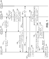
- FIG. 1 illustrates a message flow diagram of an example provisioning phase (PP).
- the provisioning phase may include UE/OP loc 102, RP 104, OPSF 106, and/or Home Subscription Service (HSS) 108.
- UE/OP loc 102 may submit a login identifier (e.g., OpenID identifier (OID) such as an http address or an email) to RP 104 at 110.
- the message at 110 may include an RP challenge value RP Chv .
- the RP challenge value RP Chv is a value to which the RP 104 may respond appropriately to prove its authenticity. For example, this may be a random value which may have a one-time use.
- RP 104 may send an association request (e.g ., http POST OpenID association request) to OPSF 106.
- the association request may include an RP credential RP Cred that corresponds to RP 104 and/or the RP challenge value RP Chv .
- RP Cred may be an identifier of RP 104 which may allow OPSF 106 to select the correct pre-shared key K r,o that is shared between OPSF 106 and RP 104.
- RP Cred may be omitted from messaging if OPSF 106 identifies RP 104 by other means (e.g ., Internet URL).
- the OPSF 106 may determine whether shared secret K 0 between the OPSF 106 and UE/OP loc 102 has been provisioned. If so, then the OPSF 106 may proceed to an authentication phase (AP) (e.g., as illustrated in FIG. 2 ). If not, then the provisioning phase may continue.
- AP authentication phase
- OPSF 106 may select a shared secret K r,o based on RP Cred or another trusted identifier of RP 104 for example.
- OPSF 106 may perform association with RP 104 at 118.
- OPSF 106 may generate association handle A and/or signing key S at 118.
- the signing key S may be generated based on a function of association handle A.
- OPSF 106 may send association handle A and the signing key S to RP 104.
- the signing key S may be encrypted with shared key K r,o which may be referred to as EK r,o (S) for example.
- RP 104 may send a redirect message to UE/OP loc 102 at 120.
- the redirect message may include parameters, such as the sessionID, the returnURL, a nonce, the login identifier (e.g., OID), and/or association handle A for example.
- UE/OP loc 102 may send a request ( e.g ., http GET request) to OPSF 106 at 122.
- the request e.g ., http GET request
- the request may include parameters, such as the sessionID, the returnURL, a nonce, the login identifier (e.g., OID), and/or association handle A for example.
- OPSF 106 may get authentication vectors and/or other information from HSS 108. OPSF 106 may send an authentication challenge to UE/OP loc 102 at 126. At 128, UE/OP loc 102 may calculate an authentication response and send the authentication response to OPSF 106. At 130, the OPSF 106 may validate the authentication response and generate a shared secret K 0 that is shared between the OPSF 106 and UE/OP loc 102. This generation of the shared secret K 0 after the validation of the authentication response may bind the establishment of the security association between the UE/OP loc 102 and the OPSF 106 to this authentication. For example, as shown in FIG.
- this binding may be a procedural binding of the validation of the authentication response to the generation of the shared secret K 0 .
- UE/OP loc 102 may generate shared secret K 0 at 132.
- OPSF 106 may generate an authentication assertion message UE Assert after authenticating the UE/OP loc 102.
- the authentication assertion may include the RP Cred and RP Chv being encrypted by K 0 , which may be referred to as K 0 (RP Cred , RP Chv ) for example.
- This authentication assertion may indicate to the UE/OP loc 102 that OPSF 106 has authenticated RP 104, so that UE/OP loc 102 may be assured that it is talking to the legitimate RP 104.
- RP Cred may be a name (or other text value) for the RP 104 which is identifiable by UE/OP loc 102.
- OPSF 106 may also encrypt authentication assertion message UE Assert with signing key S, which may be referred to as E S (UE Assert ) for example.
- E S UE Assert
- the redirect message may redirect UE/OP loc 102 to RP 104 with the signed assertion message.
- the UE/OP loc 102 may send a request (e.g ., http GET request) to RP 104 at 138 with the signed assertion message.
- RP 104 may decrypt the signing key S using shared key K r,o and/or verify the authentication assertion message (e.g ., OpenID assertion message) using the signing key S by decrypting E S (UE Assert ).
- RP 104 may send a notification to UE/OP loc 102 at 142 that includes authentication assertion UE Assert .
- UE/OP loc 102 may validate authentication assertion UE Assert by decrypting RP Chv and/or RP Cred .
- a protocol may be implemented in which a shared secret K 0 between OPSF 106 and UE/OP loc 102 may be established.
- OPSF 106 and UE/OP loc 102 may not yet share a secret.
- This shared secret may be established when the protocol is run by including a network-based authentication, using a network entity HSS 108 for example.
- HSS 108 By including RP Chv and RP Cred in UE Assert , encrypted with K 0 , the UE/OP loc 102 may be assured that the received message originated from the RP 104 identified by RP Cred .
- UE/OP loc 102 may verify that no other RP received authentication information and that the RP 104 is the intended RP to which the UE/OP loc 102 desired to perform authentication.
- the information piece RP Cred in UE Assert may be replaced by some explicit statement RP Assert generated by OPSF 106 to denote the RP 104 identity to UE 102.
- UE Assert may be a signed OpenID assertion message, signed with a signing key S.
- FIG. 1 also illustrates that the RP 104 may be authenticated ( e.g ., implicitly authenticated) to UE/OP loc 102.
- RP 104 may perform OpenID authentication of UE/OP loc 102 if it is the authentic RP identified by RP Cred (since then is it able to decrypt signing key S).
- the unique UE/OP loc 102 which is authenticated in the protocol by OPSF 106 to RP 104, may authenticate RP 104.
- the protocol flow may be unmodified from a local OpenID authentication.
- network authentication may remain unaffected. Additional cryptographic operations may be implemented at one or more parties in the protocol to ensure further protection.
- a protocol may be implemented if a pre-shared secret K 0 between UE/OP loc 102 and OPSF 106 exists.
- GBA Generic Bootstrapping Architecture
- FIG. 2 illustrates an example message flow diagram of an Authentication Phase (AP).
- the authentication phase may implement UE/OP loc 202, RP 204, OPSF 206 and/or HSS 208.
- the protocol flow illustrated in FIG. 2 may be applied independently, or in conjunction with the protocol provisioning phase (PP) described in FIG. 1 for establishment of a secure channel using a shared secret between UE/OP loc 102 and OPSF 106, such as if it does not already exist as a pre-shared key for example.
- PP protocol provisioning phase
- UE/OP loc 202 may submit a login identifier (e.g ., OpenID identifier (OID) such as an http address or an email) to RP 204 at 210.
- OID OpenID identifier
- RP 204 may send an association request (e.g ., http POST OpenID association request) to OPSF 206.
- the association request may include the RP credential RP Cred identifying RP 204.
- OPSF 206 may determine whether shared key K 0 has been determined or provisioned, and if not, the protocol may proceed with the provisioning of K 0 in the provisioning phase. If K 0 has already been provisioned, the protocol may proceed with the authentication phase.
- the OPSF 206 may select shared key K r,o based on the RP cred corresponding to RP 204.
- the OPSF 206 may perform association with RP 204.
- OPSF 206 may generate association handle A and/or shared key K 1 .
- Shared key K 1 may be a shared key between OPSF 206, UE/OP loc 202, and/or RP 204 that is generated from a function of association handle A, RP Cred , and/or shared key K 0 for example.
- the UE/OP loc 202 and/or the OPSF 206 may be configured to generate the shared key K 1 .
- the RP 204 may receive the shared key K 1 and use it for secure communications with the UE/OP loc 202.
- OPSF 206 may send association handle A and an encrypted K 1 to RP 204, where K 1 is encrypted by shared key K r,o , which may be referred to as EK r,o (K 1 ) for example.
- RP 204 may send a message to UE/OP loc 202 at 220 that includes parameters, such as a sessionID, a returnURL, a nonce, a login identifier (e.g., OID), association handle A, and/or RP Cred .
- the message at 220 may be a redirect message that redirects UE/OP loc 202 to RP 204 for example.
- UE/OP loc 202 may generate K 1 .
- K 1 may be generated from a function of association handle A, RP cred , and/or K 0 .
- UE/OP loc 202 may perform a local authentication at 222 and may generate authentication assertion message UE Assert including RP Chv and/or may encrypt UE Assert with key K 1 , which may be referred to as EK 1 (UE Assert ) for example, at 222.
- EK 1 UE Assert
- UE Assert may be an OpenID assertion message for example.
- UE/OP loc 202 may send the encrypted assertion message UE Assert to RP 204.
- UE/OP loc 202 may send a request (e.g ., http GET request) to RP 204 with the signed assertion.
- RP 204 may decrypt K 1 using K r,o at 226.
- RP 204 may decrypt authentication assertion message UE Assert at 226 using decrypted K 1 .
- RP 204 may verify OpenID assertion using shared key K 1 .
- RP 204 may send a notification to UE/OP loc 202 that includes authentication assertion message UE Assert .
- UE/OP loc 202 may validate the authentication assertion message UE Assert at 230.
- UE/OP loc 202 may be assured that the received message at 228 originated from the RP 204 identified by RP Cred and to which it submitted the login information at 210. For example, by comparing the identity claimed in RP Cred with the identity of the RP 104, UE/OP loc 202 may verify that no other RP received authentication information and that the RP 104 is the intended RP to which the UE/OP loc 202 desired to perform authentication.
- Freshness of authentication may be ensured by including a fresh challenge RP Chv in UE Assert .
- UE/OP loc 202 may validate the received UE Assert by verifying that it includes this challenge value, which RP 204 may know if it is able to decrypt UE Assert with the genuine K 1 , which may be shared by UE/OP loc 202 and RP 204.
- Use of the genuine K 1 may prove that RP 204 is in possession of K r,o shared by the OPSF 206 and the RP identified by RP Cred .
- RP authentication may be performed using the OP without local OpenID (e.g ., using non-local OpenID).
- the inclusion of RP authentication in the OpenID protocol may include changes to the OpenID protocol itself and/or changes to the implementations of the OP and/or RP.
- RP authentication may add security benefits, such as providing a countermeasure to possible attacks by a fake or rogue RP for example.
- Implementation on the UE for OpenID (or local OpenID) may not be affected by any such RP authentication.
- the UE may not incorporate local OP functionality and may not be able to send the challenge RP Chv to the RP in an embodiment.
- RP authentication may include a challenge response step between the OP and the RP, where the OP may send a challenge with a proof of freshness to the RP ( e.g., via an encrypted nonce).
- the RP may use the pre-established shared secret K r,o to decrypt this nonce and return the answer to the OP.
- the nonce may be unencrypted, and be signed by the RP in its answer.
- the response to the authentication challenge may be as a direct response to the OP authentication challenge, or it may be integrated in the redirect message, which may send the UE to the OP for example. In either case, the OP may have reliable evidence on authentication of the RP before engaging in UE authentication.
- This may allow the stoppage of the protocol in the case of a failed RP authentication, and/or save communication effort between the UE and the OP in the case of such a failed RP authentication.
- the OP may then directly convey the information on the failed RP authentication to the UE.
- FIG. 3 illustrates a message flow diagram of an example portion of the message exchange for RP 304 authentication.
- the message flow diagram includes communications between UE 302, RP 304, and OP 306.
- the OP 306 may force Hypertext Transfer Protocol Secure (HTTPS) communication with UE 302 and/or notify the UE 302 of the failure. Otherwise, OpenID authentication may proceed.
- HTTPS Hypertext Transfer Protocol Secure
- UE 302 may submit a login identifier (e.g., OID) to RP 304 at 308.
- RP 304 may send an association request (e.g ., http POST OpenID association request) at 310 to OP 306.
- the association request at 310 may include RP Cred .
- OP 306 may select the shared secret K r,o between OP 306 and RP 304 based on RP Cred or another trusted identifier of RP 304 for example.
- OP 306 may perform association with RP 304 at 314.
- OP 306 may generate association handle A, signing key S, and/or RP Chv .
- RP Chv may be encrypted using K r,o , which may be referred to as EK r,o (RP Chv ) for example.
- OP 306 may send the association handle A, signing key S, and/or EK r,o (RP Chv ) to RP 304.
- RP 304 may decrypt RP Chv at 316 using shared key K r,o .
- RP 304 may send a message to OP 306, via UE 302, which may include parameters, such as the sessionID, returnURL, a nonce, a login identifier ( e.g ., OID), association handle A, and/or RP Chv .
- the message at 318 may include a redirect message, which may redirect UE 302 to OP 306.
- UE 302 may send a message (e.g ., an http GET request) to OP 306 at 320.
- the message at 320 may include parameters such as the sessionID, the return URL, the nonce, the login identifier (e.g ., OID), association handle A, and/or RP Chv .
- OP 306 may validate RP 304's identity with RP Chv . If RP 304's identity is determined to be invalid at 324, OP 306 may send a notification at 326 to UE 302 indicating the RP 304 invalidity ( e.g ., via an HTTPS notification indicating that RP 304 is invalid). If RP 304's identity is valid, authentication (e.g ., OpenID authentication) may continue at 328 and/or OP 306 may send a notification indicating RP 304's identity is valid (not shown).
- authentication e.g ., OpenID authentication
- the RP 304 may set up a message authentication code (MAC) key which may be used to sign the authentication assertion message UE Assert .
- MAC message authentication code
- This key may be sent encrypted using a temporary secret key which may be negotiated between OP 306 and RP 304 ( e.g., using Diffie-Hellman (DH) procedure).
- DH Diffie-Hellman
- the OP 306 may include a nonce in response to the RP 304. This nonce may be encrypted with the temporary secret key (e.g., DH-key) for example.
- the RP 304 may decrypt the nonce and/or the MAC key based on the negotiated key (e.g ., DH-key).
- the RP 304 may use its own pre-established K r,o key to encrypt or sign the nonce as received from the OP 306.
- the RP 304 may add this key as a parameter to the redirect message which may be sent to the UE 302 for example. Since the UE 302 may follow the redirect to the OP 306, the OP 306 may receive the signed or encrypted nonce, and may use the shared key K r,o to authenticate the RP 304. In the case of a failed authentication, the OP 306 may send an alert message to the UE 302 to protect it from unauthenticated RPs. In the case of a successful RP authentication, the OP 306 may proceed with the protocol.
- the negotiated key e.g ., DH-key
- the OP 306 may be able to send information to the RP 304 where no association is established between OP 306 and RP 304 (e.g., a stateless mode in OpenID).
- a stateless mode information may be exchanged between the OP 306 and the RP 304, such as during discovery for example.
- the discovery involves the OP 306 (e.g., in the case of delegated discovery, where the user identifier may be for example at http://myblog.blog.com, and/or may point to the OpenID OP endpoint URL at the OP at http://myblog.myopenid.com).
- the OP 306 at myopenid.com may not be involved in the discovery directly and may not be able to authenticate the RP 304 at this stage.
- the OP 306 may dynamically generate a nonce as part of the discovery information page and/or associate it with the identifier (e.g ., URL or email address) of the HTTP requesting RP 304.
- the OP 306 may expect the RP 304 to sign or encrypt this nonce and/or include the information in the redirect message.
- the OP 306 may force the use of HTTPS.
- the UE 302 may be redirected to the use of HTTPS by the OP 306 such that any subsequent communication between the UE 302 and the OP 306 may be protected using HTTPS.
- This feature may be explicitly allowed by OpenID standards embodiments, such as OpenID Authentication 2.0 for example.
- OpenID Authentication 2.0 for example.
- Such a protection may enable the prevention of man-in-the-middle (MitM) attacks on the OpenID authentication challenge message from the OP 306 to the UE 302 for example. It may allow an alert message to be sent in the case of a failed RP authentication to the UE 302 in a protected manner.
- MitM man-in-the-middle
- the split terminal implementation may refer to a scenario where two entities may reside on the user side of the network.
- an Authentication Agent (AA) and a Browsing Agent (BA) may be associated with and/or reside on a UE, such as UE 302 for example.
- the AA may perform the steps for authentication, while the BA may be the viewer or consuming entity of the service.
- a user may open a browser to retrieve some service (e.g ., a website) from an RP, such as RP 304 for example.
- the RP 304 may perform some steps (e.g ., association and/or discovery) with the OP 306 and the user's AA.
- the UE 302 may be contacted by the OP 306.
- the OP 306 and the UE 302 may perform the authentication, for example, based on GBA network credentials, which may not be known to the BA.
- the BA may obtain access to the service at the RP 304, such as if the authentication between OP 306 and the AA was successful for example.
- the logic channel may be created by the user entering information shown on the AA into the BA, such that the two sessions may be logically combined for example.
- the Mobile Network Operator's (MNO's) own services and/or third party service provider's services may be provided to the UE 302, or to devices which are known to the MNO. If MNOs want to enable users to connect different/multiple devices with a sole authenticator (e.g ., the UE 302) a split terminal implementation may be used.
- Example options for the split terminal implementation may include those where a cryptographic binding between the two sessions is created. Implementations may also include scenarios where the AA displays credential information to the user, which the user may enter in the BA to authenticate towards the RP 304 ( e.g., using the logical channel described herein).
- the credentials may be sent over a secured local link between the BA and the AA (e.g ., using the physical channel described herein).
- the AA may be used as an authentication token/ password generator.
- the BA may receive the shared key K 1 and authentication assertion message UE Assert , which may be encrypted by K r,o and may be referred to as EK r,o (K 1 ,UE Assert ) for example, from the AA and send them to the RP 304. This information may be used by the RP 304 to authenticate the user.
- a split terminal implementation may be set up with a local assertion provider, which generates the authentication assertion message UE Assert inside the UE 302/AA.
- Added security functions may be implemented depending on an authentication based on local OpenID.
- Authentication may be based on local OpenID to provide a private secret (e.g ., encryption key E illustrated at 410 and 414 in FIG. 4 ).
- This secret may be used, for example, to establish a private, secure channel between the OP loc , and/or the trusted environment in which it resides ( e.g., a smart card or other trusted computing environment), and the RP.
- the secure channel may have an endpoint in some relatively non-secured part of the UE, which may be referred to as the UE platform.
- the secure channel may be established with a UE platform and the RP and local OpenID authentication may be performed inside this secure channel.
- This example embodiment may be sufficient for some implementations, but may not meet the security demands of others.
- a UE platform which establishes the secure channel may be less secure than the trusted environment (e.g ., a smart card or other trusted computing environment) on which the OP loc resides.
- Private data coming from the same trusted environment and directed toward the RP may travel on a channel which has a relatively insecure inner node in the UE.
- an alternative embodiment may be implemented which may allow the OP loc , and/or the trusted computing environment on which it resides, to exchange secrets with the RP independent of the properties of the UE platform, and to bind such privacy properties of a message to the local OpenID authentication to the RP.
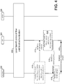
- FIG. 4 illustrates a message flow diagram of an example embodiment of creating and/or implementing a secure channel between a local authentication entity, such as UE/OP loc 402 for example, and an RP 404.
- the flow diagram illustrated in FIG. 4 includes communications between UE/OP loc 402, RP 404, and/or OPSF 406.
- a local OpenID authentication may be performed up to the point at which UE/OP loc 402 generates the signed authentication assertion at 410.
- UE/OP loc 402 may generate a signing key S, which may be derived from a function of association handle A and shared key K 0 using a key derivation function (KDF).
- KDF key derivation function
- Shared key K 0 may be shared between UE/OP loc 402 and OPSF 406 for secure communications.
- the signing key S may be an OpenID signing key for example.
- the UE/OP loc 402 may perform a local authentication and authentication assertion message UE Assert may be generated at 410 and may include an encrypted seed value (Seed).
- the Seed may be used for hiding a shared secret between two or more parties. For example, the shared secret may be hidden because the shared secret may not be transmitted between parties.
- the Seed may instead be transferred and used to derive the shared secret ( e.g., locally) at each of the parties to which the secret is shared.
- the authentication assertion message UE Assert may be an OpenID assertion for example.
- UE/OP loc 402 may encrypt the Seed with the signing key S (referred to as E S (Seed)), which may be private to OPSF 406, UE/OP loc 402, and/or RP 404.
- E S Seed
- UE/OP loc 402 may encrypt the Seed using a key derived from S in a pre-determined way.
- UE/OP loc 402 may generate the encryption key E from the Seed in a pre-determined way, which may be known to RP 404 for example.
- UE/OP loc 402 may sign the authentication assertion message UE Assert with the signing key S. This generation of the encryption key E from the local authentication may bind the establishment of the secure channel between the UE/OP loc 402 and the RP 404 to this local authentication.
- the UE/OP loc 402 may send a message (e.g ., an http GET request) to RP 404 with the signed assertion UE Assert .
- RP 404 may verify the authentication assertion message UE Assert and use the signing key S to decrypt the Seed information at 414.
- the RP 404 may generate encryption key E based on the Seed information.
- the RP 404 may generate the encryption key E from the Seed information in a pre-determined way, which may be known to UE/OP loc 402. Encryption key E may be private to UE/OP loc 402 and RP 404.
- RP 404 may encrypt the previously verified authentication assertion UE Assert with encryption key E and send it back to UE/OP loc 402. For example, at 416, RP 404 may send a notification to UE/OP loc 402 that includes the authentication assertion message UE Assert , which may be encrypted with encryption key E (E E (UE Assert )) for example. This may provide confirmation of secret establishment to UE/OP loc 402. UE/OP loc 402 may validate the authentication assertion message UE Assert at 418 by decrypting it using encryption key E.
- E E UE Assert
- UE/OP loc 402 may be assured that the received message at 416 originated from the intended RP 404. For example, by comparing the Seed in the notification received from the RP 404 at 416 with the Seed included in the UE Assert at 410, UE/OP loc 402 may verify that no other RP received authentication information and that the RP 404 is the intended RP to which the UE/OP loc 402 desired to perform authentication. The UE/OP loc 402 may trust in this verification at 418 as an indication that the RP 404 obtained the key S by which RP 404 is able to decrypt the Seed and derive E.
- encryption key E may be used ( e.g., in another protocol) to establish a secure channel between the UE/OP loc 402 and the RP 404.
- One example protocol that may be used to establish this secure channel may include the TLS-PSK protocol, which may be a variant of the common TLS protocol which accepts a pre-shared key as input and realizes a secure channel based on the pre-shared key.
- TLS-PSK is illustrated, by the Internet Engineering Task Force (IETF), in Request for Comments (RFC) documents 4279 and 4785.
- derivation of encryption key E may be performed using knowledge of the Seed and the KDF, which may be public.
- the Seed may be known to the RP 404, and may be protected from others, since it is encrypted with signing key S.
- S may be revealed to RP 404 by OPSF 406 over a secure channel, such as a certificate-based transport layer security (TLS) for example.
- UE 402 may obtain confirmation of RP 404 possessing signing key S, since RP 404 may send E E (UE Assert ) back to UE 402, which RP 404 may be able to do if it is able to decrypt Seed. Therefore, UE 402 may obtain key confirmation from RP 404.
- the protocol flow illustrated in FIG. 4 may be combined with an RP authentication protocol, such as the RP authentication protocols described herein, to enable secure communications.
- Seed information may be used to derive a private, shared key between entities
- a private, shared key may be derived in other ways.
- embodiments may implement Diffie-Hellman key establishment.
- some initial value such as the Seed for example, may be transferred between the entities wishing to establish the shared secret.
- Encryption of the Seed may be used to protect the Seed from man-in-the-middle attacks.
- Specific encryption with the signing key S, or a key derived from S, may be used for binding to the local OpenID authentication.
- the encrypted notification message may be used to bind to the local OpenID authentication. This may add the feature of confirmation toward the UE/OP loc 402 of the establishment of the secret.
- the establishment of the secret may begin earlier in the local OpenID protocol flow by the RP 404 sending an encrypted Seed in a redirect message to the UE/OP loc 402.
- the RP 404 may be an intermediate node on the path to the endpoint of the desired secure channel.
- RP 404 may receive Seed from this endpoint, which may be a server with which UE/OP loc 402 may wish to establish the secure channel and to which RP 404 may act as an authentication, and optionally an authorization, gateway.
- Encryption key E may be used in another protocol to establish a secure channel between the UE/OP loc 402, or the UE platform, and the RP 404.
- a candidate protocol for using the encryption key E in such a manner may include the TLS-PSK protocol, which may be a variant of the TLS protocol which accepts a pre-shared key as input and realizes a secure channel based on it.
- the establishment of the secret may be combined with RP authentication.
- FIG. 5 is a flow diagram illustrating the establishment of a secure channel for local OpenID authentication using a UE-RP pre-established secure channel with post-authentication key confirmation.
- secure channel establishment may allow the UE/OP loc 502, or the UE platform, and the RP 504 to establish a secure channel and proceed with local OpenID authentication.
- the flow diagram illustrated in FIG. 5 may be used to confirm the secure channel keys toward the RP 504 during authentication, and may be bound to authentication for example. This may be done by extracting key material XS from the secure channel, such as a transport-layer security (TLS) tunnel for example, and/or deriving a binding response B res from it.
- TLS transport-layer security
- UE/OP loc 502 and RP 504 may establish a secure channel at 508.
- the secure channel may be established using TLS.
- the UE/OP loc 502 may submit a login identifier (e.g., OID) to the RP 504.
- RP 504 may send an association request (e.g ., http POST OpenID association request) to OPSF 506 at 512.
- the OPSF 506 may perform association with RP 504 at 514.
- the OPSF 506 may generate an association handle A and/or a shared key K 1 .
- the shared key K 1 may be a shared key between OPSF 506, RP 504, and/or UE/OP loc 502.
- the shared key K 1 may be derived from association handle A and/or shared key K 0 .
- OPSF 506 may send association handle A and/or shared key K 1 to RP 504.
- RP 504 may send a redirect message to UE/OP loc 502 which redirects UE/OP loc 502 to the OP, which resides locally on the UE/OP loc 502.
- the redirect message may include parameters such as a sessionID, a returnURL, a nonce, the login identifier ( e.g., OID), and/or the association handle A.
- UE/OP loc 502 may perform a local authentication and may generate the shared key K 1 .
- the shared key K 1 may be generated from association handle A and/or shared key K 0 . This generation of the shared secret K 1 from the local authentication may bind the establishment of the secure channel 508 between the UE/OP loc 502 and the RP 506 to this local authentication.
- the UE/OP loc 502 may include the binding response B res in the authentication assertion message UE Assert . B res may be included in the extension fields of the authentication assertion message UE Assert , as permitted by OpenID for example.
- the authentication assertion message UE Assert may be signed by the UE/OP loc 502 using the shared key K 1 , which may be referred to as SigK 1 (UE Assert ) for example.
- the UE/OP loc 502 may send the signed assertion message SigK 1 (UE Assert ) to the RP 504.
- the signed assertion message may be sent in an http GET request.
- the XS may not be used directly in the message to RP 504, since this may leak information concerning the secure channel to an attacker.
- the RP 504 may know that the authenticated party is the secure channel endpoint, since it is in possession of the correct secure channel keys for the channel over which the authentication protocol was run, which may be used as key confirmation of the secure channel keys. If the RP 504 verifies that the binding response B res * equals the binding response B res , then authentication may be determined successful and the channel between UE/OP loc 502 and RP 504 may be secure. At 524, RP 504 may send a notification to UE/OP loc 502 indicating that authentication is successful and that the channel is secure.
- the secure channel may be established using TLS.
- the UE/OP loc 502 and the RP 504 may include within the protocol a key confirmation which may assure the RP 504 that the authenticated ( e.g ., by OpenID authentication) party may also be the endpoint of the previously established secure channel.
- the example embodiment illustrated in FIG. 5 may include the use of the OP loc as a trust anchor for the key confirmation, and the secure channel establishment, as well as the authentication.
- Embodiments attempting to achieve the same, or similar, security without the use of an OP loc may incur additional communication steps between RP 504 and a network OP.
- MitM 5 may mitigate man-in-the-middle (MitM) attacks, such as the attack in which the MitM establishes itself initially at the set-up of the secure (TLS) channel, for example, as a TLS relay.
- TLS secure
- the embodiments described herein may make the MitM explicitly detectable by the RP 504.
- XS may be used for key confirmation.
- RP 504 may do the same to verify the signed assertion.
- the RP 504 may achieve authentication and key confirmation for the secure channel concurrently. This may come at the cost of reduced semantics, since presence of the MitM may no longer be discernible from failure of the authentication.
- the embodiments illustrated in FIG. 5 may be combined with RP authentication, such as the RP authentication embodiments described herein for example.
- the assurance of channel security may be one-sided as illustrated in the protocol in FIG. 5 .
- the protocol may be combined with the RP authentication protocol, such as the RP authentication protocols illustrated in FIGs. 2 and 3 for example.
- the UE/OP loc 502 may include the encrypted challenge value EK 1 (RP Chv ) in the authentication assertion message. If K 1 was never divulged to an MitM, the UE/OP loc 502, upon receiving the notification including RP challenge value RP Chv , may assume that a valid RP 504 has performed successful evaluation of B res , and thus an MitM may not be present. Thus, if the RP 504 is in possession of the correct K 1 , it may decrypt RP Chv .
- the RP 504 may have knowledge of binding response B res .
- B res may be used to encrypt the RP challenge value RP Chv in the notification that is returned to the UE/OP loc 502 at 524.
- the UE/OP loc 502 may use K 1 ′ , rather than K 0 or K 1 for example, to encrypt RP Chv inside the authentication assertion message UE Assert .
- RP 504 may extract RP Chv if it is in possession of a K 1 ′ derived from the correct XS value.
- the authentication and key agreement protocols described herein may include various implementations for protection from attacks, such MitM attacks for example.
- One way to provide such protection is to establish a secure channel, which may be called an outer channel, such as a TLS tunnel for example, before the authentication flow.
- the authentication may be performed inside this secure channel.
- the protocol referred to as GBA_H may be sufficiently secure against an attack with respect to the outer authentication protocol established by the TLS tunnel.
- GBA_H may include an authentication procedure which is based on HTTP digest over a TLS for example.
- 3GPP 3rd Generation Partnership Project
- TS Technical Specification
- FIG. 6 illustrates a message flow diagram showing an example of the GBA_H protocol using HTTP-SIP digest.
- communications may be performed using a UE 602, a BSF 604, and/or an HSS 606.
- the UE 602 may establish a TLS tunnel with BSF 604.
- the UE 602 may send a request to BSF 604 at 610, using the TLS tunnel for example.
- the request at 610 may include an authorization header comprising a private identity, as illustrated at 612.
- BSF 604 and HSS 606 may use the Zh reference point at 614 to exchange authentication information.
- the Zh BSF 604 may use the Zh reference point to retrieve authentication vectors (AVs) and/or user profile information from HSS 606.
- AVs authentication vectors
- BSF 604 may send an authentication challenge (e.g ., an authentication challenge in an HTTP 401 unauthorized response) to UE 602.
- the message at 618 may include private identity information, a realm, a nonce, a quality of protection (qop) value, an authentication algorithm, a domain, and/or an opaque.
- this information may be included in the authentication header of the message.
- the private identity information may include the identity which the network uses to identify the user. This private identity may enable the network to retrieve the user profile and/or the authentication vector for the challenge.
- the realm, nonce, qop value, authentication algorithm, domain, and/or opaque may be illustrated, by the IETF, in RFC document 2617.
- the UE 602 may calculate an authentication response.
- the UE may send the authentication request to BSF 604 at 624.
- the authentication request may include the private identity information, the realm, the nonce, a cnonce, the qop value, a nonce count, an authentication algorithm, a digest uri, and the opaque.
- the cnonce, the nonce count, and/or the digest uri may be illustrated, by the IETF, in RFC document 2617.
- the BSF 604 may calculate a response and compare the values received from the UE 602 with the calculated values at the BSF 604.
- the BSF 604 may send a message (e.g ., a 200 OK message) to the UE 602 that confirms to the UE 602 that authentication was successful.
- the message at 630 may include a binding trusted identifier (B_TID) and/or a key Ks lifetime, as illustrated at 632.
- B_TID binding trusted identifier
- Ks lifetime may be illustrated, in 3GPP TS number 33.220.
- the UE 602 and the BSF 604 may calculate the Ks_NAF.
- Another example embodiment may include a binding between the TLS outer authentication and the authentication established by the GBA mechanism a described herein.
- the proposed binding solution may be formulated by, for example, the UE 602 adding a binding response B res to the message at 624.
- B res may depend on the secure channel in a way that is known to BSF 604 and UE 602, but not an MitM.
- B res may be derived from secure channel messages in a similar (or even the same) way as the inner authentication (e.g ., AKA) response, but it may be independent of the response.
- the B res may not be derived from a response in a common, publicly known way, otherwise an MitM may be able to derive the B res in a similar manner.
- BSF 604 may perform verification of B res using parameters from the secure channel BSF 604-MitM which differ from those of the secure channel UE 602-MitM.
- a precondition for this may include a uniqueness of the secure channel which may be satisfied by protocols, such as TLS for example, where both BSF 604 and UE 602 may be able to introduce their own chosen parameters ( e.g ., nonces) in the channel establishment.
- Verification and/or recalculation of B res may fail if performed by an MitM, because the MitM may not know how to derive an acceptable B res value, while recalculation of the GBA response by the MitM may succeed. In this way, the MitM may be detected.
- the UE 602 may take the TLS encryption key and hash it using a keyed hash function H where the key depends on the AKA authentication challenge. This may be posed by the BSF 604 in the message at 618.
- the AV may be formatted properly and fed directly into the GBA response calculation algorithm in place of an AKA challenge value. This may mitigate replay and may bind the secure TLS channel 608 to the GBA authentication run.
- a binding of the secure channel 608 to the challenge-response authentication 618-630 may be established.
- the UE 602 may, after having received the authentication challenge 620 (e.g., the inner_auth_challenge), apply a digest algorithm H (e.g., an HMAC algorithm) with a TLS_key extracted from the TLS channel at 608 to obtain a modified challenge*.
- H e.g., an HMAC algorithm
- H e.g., an HMAC algorithm
- TLS_key extracted from the TLS channel at 608
- This may be represented as H(TLS_key, inner_auth_challenge) -> challenge*, for example.
- An example embodiment of a key extraction method for TLS is illustrated, by the IETF, in RFC document 5705.
- the UE 608 may calculate the response to the challenge posed by BSF 604 at 622, and concurrently calculate a binding response B res using the same, or similar algorighm. This may be represented as AKA-RESPONSE (inner_auth_challenge)-> response; AKA-RESPONSE (challenge*, IK) -> B res , for example.
- the UE may send both the response and B res back to BSF 604 at 624.
- BSF 604 may obtain assurance of the binding by way of checking the UE 602 response. If the response is confirmed, BSF 604 knows the entity at the other end of the communication is authenticated. If B res is also confirmed, where BSF 604 uses its own end's TLS key for verification, the authenticated entity may also be the one having the TLS tunnel with BSF 604, otherwise a MitM may be suspected.
- FIG. 7 is a diagram of an example call flow binding TLS and GBA with SIP-Digest authentication.
- the UE 702 may start the bootstrapping procedure by initiating a TLS session with the BSF 704.
- the UE 702 may authenticate the BSF 704 by the certificate presented by the BSF 704.
- the BSF 704 may not require authentication from the UE 702 at this point.
- the UE 702 may send a request message (e.g ., an HTTP GET request) at 710 that includes a private identifier (e.g., IP multimedia subsystem private identifier (IMPI)) to the BSF 704.
- a request message e.g ., an HTTP GET request
- a private identifier e.g., IP multimedia subsystem private identifier (IMPI)
- the BSF 704 may request authentication information (e.g ., AV(s)) from the HSS 706 at 712.
- the HSS 706 may provide the requested data (e.g ., including the AV(s)) to the BSF 704.
- the BSF 704 may send to the UE 702 an authentication challenge (e.g., in an HTTP 401 unauthorized response) at 716.
- the authentication challenge may include an authentication header and/or a randomly generated nonce.
- the authentication header may include additional parameters such as a private identity, a realm, a qop value, algorithm information, and/or a domain.
- the UE 702 may generate a random cnonce, and calculate the authentication response by using SIP Digest credentials.
- the UE 702 may also generate a messages authentication code (MAC) value B res , using both the TLS tunnel session key and a session key for example.
- the TLS tunnel session key and/or the session key may include the integrity key (IK) or the confidentiality key (CK) for example.
- the IK may be used instead of the CK, as the IK may be designated to be used for integrity protection purposes.
- These keys may be generated from the authentication challenge RAND taken from the AV the UE 702 has received. This may bind the TLS tunnel authentication with the GBA protocol.
- Both the authentication challenge response, and B res may be put into the authorization header and sent back to the BSF 704 in a request message (e.g ., an HTTP GET request message) at 720.
- B res may be calculated by the same algorithm as the authentication response, however it may be calculated with different input parameters as described.
- the BSF 704 may check B res against its own expected value, B res *. It may do so because it knows both the keys used in the calculation of B res and the expected authentication response. If the received B res matches B res *, and the received authentication response matches its expected value, the BSF 704 may determine that the UE 702 is authentic and also may assure itself that, because of the binding effect verified from the matching of the two comparisons, the UE 702 that it authenticated in the formation of the TLS tunnel is the same UE 702 that it authenticated in the GBA aspect of the protocol. The BSF 704 may generate bootstrapping key material, such as the key lifetime of the GBA/GAA master session key Ks and B-TID at 722.
- BSF 704 may send to the UE 702 a message (e.g ., a 200 OK message) including the B-TID and the key Ks.
- the UE 702 and/or the BSF 704 may derive bootstrapping key material Ks_NAF using Ks.
- Ks_NAF may be used to secure the Ua reference point.
- the application specific key for security over the Ua reference point may be derived, at least in part, from a bootstrapped key via GBA.
- the binding may still be effective if Ks_NAF is derived from both Ks and the master key established during the formation of the TLS tunnel.
- Ks_NAF may be shared between the UE 702 and the network. It may not be available to any MitM.
- the embodiments described herein may be implemented in a cloud computing scenario.
- traits and/or technical features of the local OpenID may be combined to enable multi-tenant capable cloud access from one or more private devices.
- local OP authentication, RP authentication, secret establishment, and/or enrollment procedures may be combined.
- At least two aspects of outsourcing for computing resources of an organization may be combined as described herein.
- the modern workforce class of remote, external, mobile, and field workers may encourage an organization to make use of workers' private devices for work purposes.
- information and computing resources may be increasingly outsourced to computer clouds (e.g ., multi-tenant hosting infrastructures and/or servers).
- the outsourcing organization's security requirements in this dual outsourcing scenario may set constraints on the security architecture chosen for its implementation. These may be described in terms of protection goals and/or security controls which may be used to protect the organization's assets for example.
- the user device may be considered insecure. Even if full protection of the corporate data may not be possible on a device, the organization's data may at least be secured in the cloud storage, such as to prevent data loss and/or leakage through user devices, to the extent possible.
- One way to do this may be to allow access to the cloud via a remote desktop application, which may connect to a virtual workstation in the cloud for example. As a benefit, this may allow remote workers and/or the virtual workstation to use a different operating system (OS).
- OS operating system
- the user device may be a tablet running an ANDROIDTM or APPLE® OS, and may connect to a MICROSOFT WINDOWS® virtual machine, such as via some remote desktop protocol (RDP) client application for example.
- RDP remote desktop protocol
- User authentication may be secured by hardware protection measures at the user's end, which may be bound to a smart card or other trusted environment for example. As described herein a smart card or other trusted environment may be issued that is enabled with local OpenID to the user(s) of the user equipment. User accounts may be enrolled for use in the smart card or other secure environment embodiments described herein.
- the cloud host may provide some security controls and/or contractual guarantees.
- the organization using the cloud service may establish further, independent security control against data loss and/or leakage in such a multi-tenant environment.
- the organization's IT department may install a disk encryption solution for the (virtual) hard drives of the cloud workstations.
- the protection offered by a disk encryption on cloud computers may be limited.
- the cloud host's hypervisor may have full data access while the virtual workstation is in operation.
- the cloud host's hypervisor may listen to the sent credentials used to decrypt the hard drive, when a user logs on to the workstation.
- the disk encryption may be bound in some way to the hosting hardware, such as by using Trusted Computing based virtualization support technology for example.
- the remote user device may submit secret data, such as a disk encryption credential (e.g ., a password) for example, to the virtual machine in the cloud.
- secret data such as a disk encryption credential (e.g ., a password) for example, to the virtual machine in the cloud.
- a disk encryption credential e.g ., a password
- This credential may be secretly stored on the smart card or other trusted environment enabled with local OpenID in such a way that it is transferred to the designated virtual machine.
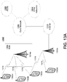
- FIG. 8 illustrates a diagram of an example communications system that implements a local authentication entity and cloud/remote computing services.
- a corporate user may obtain a smart card 818, or other trusted environment for example, from the company 814.
- the smart card may be a local OpenID-enabled smart card.
- the smart card 818 may include an OP loc for example.
- the smart card 818 may include a credential vault for private access to the company 814 resources hosted elsewhere, such as in the cloud-hosted virtual machine (VM) 810.
- VM virtual machine
- the company 814 may connect to the cloud-hosted VM 810 and store/upload company 814 information, services, documents, and/or the like for access by a user device 802 via smart card 818.
- the user may insert the smart card 818 (e.g., a smart card that is enabled with local OpenID technology to perform OP loc functions) into the user device 802 at 820.
- the user device 802 may be a tablet, smartphone, mobile phone, laptop computer, or other mobile device for example.
- the user device 802 is not required to be a mobile device, but may be any other computing device configured to access services on the cloud-hosted VM 810 using the smart card 818 or other trusted environment.
- Some applications may be installed on the user device 802, which may include a remote desktop protocol (RDP) client to access the remote desktop on the cloud-hosted VM 810 for example.
- RDP remote desktop protocol
- the login to the remote desktop may be mediated through a web-based gateway 806, which may act as an RP for the smart card authentication (e.g., OpenID authentication) procedure.
- This RP 806 may reside in the cloud-hosted VM 810 or may be an independent entity.
- the RP 806 may be offered as a security service to outsourcing companies, or it may be operated by the company 814 itself.
- the gateway RP 806 may have a secure, private connection at 808 to the cloud-hosted VM 810.
- the local OpenID-based log-on may combine one or more of at least three security features described herein.
- the local OpenID-based log-on may include: (1) authentication of a user via OP loc ; (2) authentication of the RP 806 (e.g., the security gateway) to the OP loc on the smart card 818; and/or (3) establishment of a private secret, end-to-end between smart card 818 and RP 806, and optionally delegated further to the cloud-hosted VM 810.
- Authentication of the user via the OP loc on the smart card 818 may include (at least) two-factor authentication by way of possession of the smart card 818 and knowledge of an authentication secret, and biometric user authentication.
- the authentication and/or secret communication may be performed via a secure communication between user device 802 and RP 806 at 804.
- Authentication of the RP 806 to the OP loc on the smart card 818 may extend to the user to ensure the user connects to the designated corporate resource and not to a spoofed site.
- the credentials for RP 806 authentication may be included securely in the smart card 818.
- the RP 806 may delegate the secret with the user device 802 to the cloud-hosted VM 810, or act as a middle point of two secure channels for example.
- the credential vault on the smart card 818 may be unlocked.
- the credentials for data access on the cloud-hosted VM 810 may be encrypted with the established secret (e.g., on card) and/or submitted to the cloud-hosted VM 810.
- the credential may be decrypted and verified and, if the verification is successful, the secret may be used to decrypt user data.
- the user may work on the cloud-hosted VM 810 via the remote desktop application.
- the user may have access to corporate resources via a secure connection from the cloud-hosted VM 810 to the corporate Intranet for example.
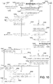
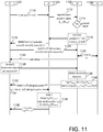
- FIG. 9 illustrates an example protocol flow that uses SIP Digest authentication and includes RP 904 authentication in OpenID.
- the authentication may include authentication of a UE 902 toward the OP 908 using a pre-shared key K r,o between the RP 904 and the OP 908.
- the RP authentication in the OpenID authentication may, in turn, be bootstrapped from SIP Digest authentication.
- the protocol flow illustrated in FIG. 9 includes communications between UE 902, RP 904 (e.g., Application Server), OP 908 (e.g., Single-Sign-on (SSO) Server), and HSS 910.
- RP 904 and OP 908 may have pre-established a shared secret K r,o at 906 that is used for secure communication between the entities.
- OpenID may be used in its stateless mode for UE 902 authentication.
- a combination of steps 912 to 918 may be used to achieve RP 904 authentication at the OP 908.
- UE 902 may register in an internet protocol (IP) multimedia subsystem (IMS).
- IP internet protocol
- IMS internet protocol multimedia subsystem
- the UE 902 may send an authentication request (e.g ., OpenID authentication request) to the RP 904 at 914.
- the authentication request may include an authentication identifier (e.g., OID).
- RP 904 may send a redirect request to UE 902 at 916.
- the redirect request at 916 may redirect the UE 902 to the OP 908.
- the redirect request may include the authentication identifier (e.g., OID) and/or the RP credential RP Cred that corresponds to RP 904.
- the RP Cred may be signed with the pre-shared key K r,o that is shared with OP 908.
- UE 902 may send a redirect request message to OP 908.
- the redirect request message may include the authentication identifier (e.g., OID) and/or the RP credential RP Cred received from RP 904 at 916.
- OP 908 may perform authentication of RP 904 using the RP Cred and/or generate an RP authentication assertion. OP 908 may also perform a check of shared key K 0 , which may be a shared key between UE 902 and OP 908, to ensure secure communications between UE 902 and OP 908. At 922, OP 908 may determine whether RP 904 has been authenticated. If RP 904 is not properly authenticated at 922, OP 908 may send an alert to UE 902 at 924 indicating that RP 904 is a bad RP and to terminate the procedure. If RP 904 is properly authenticated at 922, then OP 908 may continue with the protocol.
- the generation of the RP 904 authentication assertion at 920 may occur if the RP 904 is determined to be authentic at 926.
- the RP 904 authentication decision at 922 is considered as the point in which OP 908 makes the decision on RP authentication, then RP Assert usage may be omitted from the protocol in the steps following the RP 904 authentication decision.
- RP Cred may be a plain text identifier of the RP 904 (i.e., not signed with any key), which may allow OP 908 to select the correct shared key K r,o for further use.
- RP Cred may decide to terminate procedure and notify UE 902.
- SIP-Digest authentication may be performed.
- OP 908 may obtain an SIP digest authentication vector (SD-AV) and/or user profile information from HSS 910 at 928.
- SD-AV SIP digest authentication vector
- the OP 908 may obtain such information based on user credentials (e.g ., username/password).
- the OP 908 may also obtain user credentials, a realm, a qop value, an authentication algorithm, and/or a hash H(A1) from HSS 910.
- the realm, qop value, authentication algorithm, and/or has H(A1) may be illustrated, by the IETF, in RFC documents 2069 and 2617.
- OP 908 may generate a nonce and store the nonce and H(A1). OP 908 may send an authentication challenge (e.g ., an HTTP 401 unauthorized message with an authentication challenge) to the UE 902 at 932.
- the authentication challenge may include the user credentials, the nonce, the realm, the qop value, and/or the authentication algorithm.
- UE 902 may generate a cnonce, H(A1), and/or secret key K 0 shared with OP 908 for secure communications.
- UE 902 may also calculate a challenge response and send the challenge response (e.g ., an HTTP GET message with authentication response) at 936 to OP 908.
- the challenge response may include the cnonce, the response, the nonce, the user credentials, the realm, the qop value, the authentication algorithm, a digest-url, and/or a nonce-count.
- the cnonce, the nonce, the realm, the qop value, the authentication algorithm, the digest-url, and/or the nonce-count may be illustrated, by the IETF, in RFC document 2617.
- the shared key K 0 may be derived from the authentication response which may bind the shared key K 0 to the SIP Digest authentication.
- the OP 908 may check against the nonce, calculate an Xresponse, and/or compare the Xresponse with the response received from UE 902.
- OP 908 may generate a UE authentication assertion UE Assert and/or shared key K 0 at 938.
- OP 908 may generate a nonce1 and/or K 1 , which may be a shared key between UE 902, OP 908, and/or RP 904 that is used to establish a secure channel between the UE 902 and the RP 904.
- K 1 may be generated by the OP 908 using nonce1 in the generation for freshness.
- K 0 may be used to encrypt nonce 1 and/or the RP authentication assertion message RP Assert , which may be referred to as EK 0 (nonce 1 , RP Assert ) for example. Encryption with K 0 may enable the rightful, authenticated UE 902 to obtain RP Assert , which may be a confirmation to the UE 902 that it is communicating with the intended, authentic RP 904.
- the OP 908 may use shared key K r,o to encrypt key K 1 and/or UE authentication assertion message UE Assert , which may be referred to as EK r,o (K 1 , UE Assert ) for example.
- OP 908 may send a redirect message to UE 902, which may redirect UE 902 to RP 904.
- the redirect message may include EK 0 (nonce1, RP Assert ) and/or EK r,o (K 1 , UE Assert ).
- the RP authentication assertion message RP Assert may become obsolete at a certain point in the protocol flow, as illustrated at 944, as the OP 908 may be the decision point on RP 904 trustworthiness.
- K 1 may be used when RP 904 performs communications with UE 902, such as performing implementation specific steps 952 and/or 954 for example, to ensure that UE 902 is communicating securely with the intended RP 904.
- UE 902 may decrypt the nonce1 and/or RP authentication assertion message RP Assert using K 0 .
- the UE 902 may confirm that it is communicating with the intended, authentic RP 904.
- UE 902 may obtain the RP authentication assertion message RP Assert and nonce 1.
- the UE 902 may authenticate the RP 904 based on the received RP authentication assertion RP Assert.
- UE 902 may generate K 1 using nonce1. Encryption with shared key K 1 may enable the rightful, authenticated UE 902 to obtain UE Author , which may serve as an access token for use with services.
- UE 902 may be redirected to RP 904 at 948.
- UE 902 may send key K 1 and the UE authentication assertion message UE Assert to RP 904.
- the key K 1 and UE Assert may be encrypted with shared key K r,o , which may be referred to as EK r,o (K 1 , UE Assert ) for example. This encryption may have been performed previously by the OP 908.
- RP 904 may decrypt EK r,o (K 1 , UE Assert ) using K r,o and obtain UE Assert and K 1 .
- Information for UE 902 may be authorized at 950.
- RP 904 may use K 1 to verify the signature of UE Assert . After successfully verifying UE Assert , RP 904 may generate authorization information UE Author , which may be encrypted with key K 1 and referred to as EK 1 (UE Author ) for example. UE Author may include authorization information or an authorization parameter that indicates that the UE 902 is authorized to access one or more services at the RP 904. RP 904 may notify UE 902 at 952 as to whether UE 902 is authorized for services at RP 904. For example, RP 904 may send the UE authorization parameter or information UE Author . UE Author may be encrypted with secret key K 1 (EK 1 (UE Author )) shared between UE 902 and RP 904.
- K 1 secret key
- UE 902 may decrypt EK 1 (UE Author ) and may access the requested service from the RP 904 using the UE Author .
- Steps 952 and/or 954 may be implementation specific steps, which may be optional and may depend on the service implementation of UE 902 and/or RP 904. For example, these may be specific to the desired application of providing UE 902 with generic service access after authentication. If these steps are not used, then K 1 may not be needed.
- the protocol flow illustrated in FIG. 9 may use the secret K r,o to achieve RP 904 authentication toward OP 908.
- the secret K r,o may be used for authentication if it is not used to sign the message with the RP Cred ( e.g ., in the steps 912 to 918) towards the OP 908.
- this secret may be used for RP 904 authentication with the OP 908.
- the discovery and (optional) association creation steps of the authentication protocol (e.g ., OpenID protocol) are not shown in the protocol illustrated in FIG. 9 .
- the implementation on the UE 902 may not be affected by any such RP 904 authentication.
- the UE 902 may not include OP loc functionality and, therefore, may not be able to send the challenge RP Chv to the RP.
- FIG. 10 illustrates a message flow diagram of an example protocol with RP 1004 authentication toward the OP 1008.
- communications may be performed between a UE 1002, RP 1004 (e.g., Application Server), OP 1008 (e.g., SSO server), and/or HSS 1010.
- RP 1004 and OP 1008 may have a pre-established shared secret, illustrated at 1006, for enabling secure communications via a secure channel.
- the UE 1002 may issue an authentication request (e.g ., an OpenID authentication request) to the RP 1004 at 1012 which includes a login identifier (e.g ., OpenID identifier such as a URL or an email address).
- the RP 1004 may discover the OP 1008 at 1014.
- the RP 1004 may send an association request (e.g ., OpenID association request) to the OP 1008.
- the RP 1004 and the OP 1008 may establish a Diffie-Hellman Key D-H.
- OP 1008 may generate an association secret and/or an association handle, which may together be called association.
- the OP 1008 may send RP 1004 an association response, which may include the association secret and a nonce0.
- the association secret and/or the nonce0 may be encrypted with the established D-H key.
- the RP 1004 may decrypt the received encrypted nonce0 and encrypted association secret at 1020.
- the RP 1004 may then sign nonce0 with shared key K r,o , which may be the pre-established key shared between RP 1004 and OP 1008.
- HMAC or another suitable symmetrical signature algorithm may be used to sign nonce0.
- the RP 1004 and the OP 1008 may have a shared secret K r,o using a known mechanism, for example, using the Diffie-Hellman Key Exchange protocol or pre-shared secret. With this shared secret, the OP 1008 and the RP 1004 may sign messages and verify each other's messages that have been signed with the shared secret K r,o .
- the RP 1004 may redirect the authentication request sent by the UE 1002 using a redirect message.
- the redirect message may include the login identifier (e.g ., OpenID identifier), the RP 1004 identifier (RP Cred ), and/or the signed nonce0.
- the UE 1002 may be redirected to the OP 1008.
- the authentication request may be redirected to the OP 1008 at 1024.
- the redirection may include the login identifier (e.g ., OpenID identifier) and/or RP Cred .
- the OP 1006 may enforce the use of HTTPS for communication with UE 1002 at 1026 for secure communications.
- Enforcement of the use of HTTPS may be performed by configuration of the OP 1002's web server (e.g ., address rewrite).
- the OP 1008 may verify the signature of nonce0 to authenticate the RP 1004. For example, the OP 1008 may verify the signature using shared key K r,o .
- the RP 1004 authentication of step 1028 may be determined at 1030, and if it fails, the OP 1008 may send an alert message to the UE 1002 at 1032, which may be protected by HTTPS for example, to indicate RP 1004 authentication failure. If RP 1004 authentication at step 1028 succeeds, the protocol flow may proceed, such as at step 1034 for example.
- the OP 1008 may determine if a secure channel has been established between the OP 1008 and the UE 1002. For example, the OP 1008 may determine if a valid key K 0 exists. If the valid key K 0 does exist, the protocol flow may proceed to step 1048 with the generation of UE authentication assertion UE Assert . If a valid key K 0 does not exist, the protocol flow may proceed to perform authentication of UE 1002. In an example embodiment, the establishment of the secure channel ( e.g., as illustrated in FIG. 4 ) and the authentication of the UE 1002 may be bound together in the same protocol flow.
- the OP 1008 may send an authentication request to the Home Subscription Server (HSS) 1010, and may obtain the SIP Digest authentication vector (SD-AV) and/or the user profile based on the user credential from the HSS 1010.
- the SD-AV may include a qop value, an authentication algorithm, a realm, and a hash, called H(A1), of the user credential, realm, and password.
- the OP 1008 may obtain the address of the HSS 1010 where the details of the UE 1002's subscription are stored by querying the Service Layer Function (SLF).
- SLF Service Layer Function
- the OP 1008 may generate a random nonce, and may store the hash H(A1) and the nonce against the user credentials.
- the OP 1008 may send ( e.g., in a protected HTTPS message) an authentication challenge message (e.g ., a 401 authentication challenge as an SIP-Digest authentication challenge) at 1040 to the UE 1002 which may include the nonce, the realm, the qop value, the authentication algorithm, and/or the user credential.
- an authentication challenge message e.g ., a 401 authentication challenge as an SIP-Digest authentication challenge
- the UE 1002 may include the nonce, the realm, the qop value, the authentication algorithm, and/or the user credential.
- the UE 1002 may generate a random cnonce and the H(A1) at 1042.
- the UE 1002 may generate the shared secret K 0 based on the H(A1), the cnonce, and/or other information, such as the material included in the authentication challenge for example.
- the shared secret K 0 may be a shared secret between the UE 1002 and the OP 1008, which may enable communications between the UE 1002 and the OP 1008 to be transmitted using a secure channel.
- the UE 1002 may use the cnonce and/or other parameters provided in the authentication challenge, such as the nonce, the user credentials, and/or the qop value for example, to calculate an authentication response.
- the UE 1002 may send a challenge response (e.g ., which may be a protected HTTPS message) to the OP 1008.
- the challenge response may include the cnonce, the nonce, the response, the realm, the user credentials, the qop value, the authentication algorithm, the nonce-count, and/or the Digest-url for example.
- the OP 1008 may use the previously stored nonce to check against the nonce included in the response.
- the OP 1008 may calculate the expected response (Xresponse) using the previously stored hash H(A1) and the nonce together with other parameters included in the response (e.g ., cnonce, nonce-count, qop value, etc.) and may use this to check against the response received from the UE 1002. If the check is successful, the authentication of the UE 1002 may be considered to have succeeded. If the check is unsuccessful, the authentication may be considered to have failed. If the UE 1002 is successfully authenticated, the OP 1008 may generate the shared secret K 0 , which may be generated based on the hash H(A1), the cnonce, and/or other information, such as the material included in the authentication challenge for example. Alternatively, or additionally, upon receiving the response at 1044, the OP 1008 may create an authentication assertion UE Assert . The UE Assert may be signed using the association secret, which may be the association secret used in the message at 1018 for example.
- the OP 1008 may generate a random nonce1 and/or may generate a shared secret K 1 based on K 0 and nonce1.
- the shared secret K 1 may be a shared secret between UE 1002, OP 1008, and/or RP 1004 for establishing a secure channel between the UE 1002 and the RP 1004.
- the OP 1008 may encrypt the nonce1 using K 0 , which may be referred to as EK 0 (nonce1) for example, and may encrypt the K 1 and the signed assertion message UE Assert using K r,o , which may be referred to as EK r,o (K 1 , signed(UE Assert )) for example.
- the OP 1008 may send the UE 1002 a message (e.g ., a redirect message) at 1052 which may include EK 0 (nonce1) and/or EK r,o (K 1 , signed(UE Assert )) with redirection to RP 1004.
- the UE 1002 may decrypt the EK 0 (nonce1) using shared key K 0 and may obtain the nonce1.
- the UE 1002 may generate the shared secret K 1 based on the K 0 and the nonce1.
- the message sent by the OP 1008 may be redirected to the RP 1004 at 1056.
- the message at 1056 may include EK r,o (K 1 , signed UE Assert ).
- the RP 1004 may decrypt the EK r,o (K 1 , signed UE Assert ), and obtain UE Assert and K 1 at 1058. RP 1004 may verify the signature of the assertion message UE Assert using the association secret shared with OP 1008. After verifying the assertion message UE Assert , the RP 1004 may generate authorization information for the UE 1002. For example, the RP 1004 may generate authorization information UE Author and encrypt UE Author using K 1 , which may be referred to as EK 1 (UE Author ) for example. The RP 1004 may notify the UE 1002 at 1060 about the application-specific authorization information, which is included in this message, encrypted with K 1 . The UE 1002 may decrypt the EK 1 (UE Author ) at 1062 using shared key K 1 and may then access the requested service.
- EK 1 UE Author
- the authorization information or parameter UE Author may be specific to an application and/or specific to OP 1008. If the UE Author is specific to OP 1008, UE Author may be signed by K 0 . If the authorization information or parameter UE Author is specific to an application, UE Author may be signed by either K r,o or signing key S. The transfer may work with signing key S.
- the protocol flow illustrated in FIG. 10 may be implemented in using a split terminal scenario as described herein.
- RP 1004 authentication may be included in a challenge-response step between OP 1008 and RP 1004, where the OP 1008 may send a challenge with a proof of freshness to the RP 1004 ( e.g., via a nonce).
- the RP 1004 may use the pre-established shared secret K r,o to sign this nonce and return the answer to the OP 1008.
- the response to the authentication challenge may be as a direct response to the OP 1008 authentication challenge, or may be integrated in the redirect message, which sends the UE 1002 to the OP 1008. In either case, the OP 1008 may have reliable evidence on the authentication of the RP 1004 ( e.g., before engaging in UE authentication).
- the OP 1008 may directly convey the information on the failed RP 1004 authentication to the UE 1002, as illustrated at 1032 for example.
- associations may be used for RP 1004 authentication. For example, if the RP 1004 establishes an association with the OP 1008, the corresponding steps may be modified to incorporate the challenge from the OP 1008.
- the OP 1008 and RP 1004 may set up a MAC key which may be used to sign the authentication assertion message. This key may be sent encrypted using a temporary secret key which may be negotiated between OP 1008 and RP 1004, using Diffie-Hellman (DH) key for example.
- DH Diffie-Hellman
- the OP 1008 may include a nonce, which may also be encrypted with the DH-key for example, in the response to the RP 1004.
- the RP 1004 may decrypt the nonce and the MAC key based on the negotiated DH-key.
- the RP 1004 may use its own pre-established shared key K r,o to sign or encrypt the nonce as received from the OP 1008 and add it as an additional parameter to the redirect message which is sent to the UE 1002. Since the UE 1002 follows the redirect to the OP 1008, the OP 1008 may receive the signed or encrypted nonce, and may use the shared key K r,o to authenticate the RP 1004. In the case of a failed authentication, the OP 1008 may send an alert message to the UE 1002 to protect it from unauthenticated RPs. In the case of a successful RP 1004 authentication, the OP 1002 may proceed with the protocol.
- Example embodiments are described for using a discovery mode for RP 1004 authentication.
- the OP 1008 may be able to send information to the RP 1004, in the case where an association is not established between OP 1008 and RP 1004 (i.e., a stateless mode in OpenID).
- the information exchange between OP 1008 and RP 1004 may take place during discovery.
- the discovery may or may not involve the OP 1008, such as in the case of delegated discovery for example.
- the user identifier may be, for example, at http://myblog.blog.com, and then point to the OP endpoint URL at OP 1008 ( e.g., at http://myblog.myopenid.com).
- the OP 1008 (e.g., at myopenid.com) may not be involved in the discovery directly and may not be able to authenticate the RP 1004 at this stage.
- the OP 1008 may be able to authenticate the RP 1004 during association at 1016, 1018, instead of determining authentication at 1028, 1030, as illustrated in FIG. 10 for example.
- the OP 1008 may be able to provide additional information during the discovery steps to the RP 1004 (i.e., the user identifier page is hosted at the OP 1008 itself), the OP 1008 may dynamically generate a nonce as part of the discovery information page and associate it with the identifier (e.g ., URL or email address) of the HTTP requesting RP 1004. The OP 1008 may then expect the RP 1004 to sign or encrypt this nonce and include the information in the redirect message.
- the identifier e.g ., URL or email address
- the OP 1008 may protect communications between the OP 1008 and the UE 1002.
- the OP 1008 may force the use of HTTPS (i.e., the UE 1002 may be redirected to the use of HTTPS by the OP 1008 such that any subsequent communication between UE 1002 and OP 1008 may be protected).
- TLS may be used. TLS may work by forcing the UE 1002 to automatically import the OP 1008's certificate, or to use a pre-installed OP certificate. Both may be checked against a root certificate (e.g ., signed by a root CA) by the BA, for example.
- a root certificate e.g ., signed by a root CA
- Such a protection may allow it to prevent MitM attacks on the authentication challenge message from OP 1008 to UE 1002 at 1040 for example. Also, in the case of a failed RP 1004 authentication, it may allow the OP 1008 to send an alert message to the UE 1002 in a protected manner.
- Embodiments described herein may be implemented with a local assertion provider. Described herein are example protocols that reconcile RP authentication with OpenID and make use of the local assertion provider.
- the described embodiments may enable authentication of the RP when there is contact (e.g., the first contact) between the RP and the (network-side) OP, based on the pre-established shared secret K r,o between the RP and the OP. In the association mode of OpenID, this is the association phase.
- FIG. 11 illustrates an example embodiment of a message flow diagram of a provisioning phase with a local assertion provider.
- a UE 1102, an RP 1104, an OP 1106, and/or an HSS 1108 may be implemented in communications performed in the provisioning phase with the local assertion provider.
- nonces may be implemented for replay protection.
- UE 1102 may submit a login identifier (e.g., OID) at 1110 to RP 1104.
- RP 1104 may send an association request (e.g ., an http POST OpenID association request) at 1112 to an OP 1106.
- the association request may include the RP 1104 credential RP Cred , which may be encrypted with the shared key K r,o which is shared between RP 1104 and OP 1106.
- This encrypted RP Cred may be referred to as EK r,o (RP Cred ) for example.
- the RP credential RP Cred may be a generic type of credential which may include be a pre-shared secret or an identifier.
- OP 1106 may determine whether shared key K 0 exists. If shared key K 0 does exist, the OP 1106 may proceed with an authentication phase (AP). If the shared key K 0 does not exist, then the OP 1106 may proceed with the provisioning phase. For example, the OP 1106 may proceed to step 1116.
- AP authentication phase
- the OP 1106 may perform association with RP 1104. For example, the OP 1106 may generate association handle A and/or signing key S. Signing key S may be generated from a function of association handle A. OP 1106 may encrypt signing key S with key K r,o , which may be referred to as EK r,o (S) for example. OP 1106 may send association handle A and/or the encrypted signing key S to RP 1104. At 1118, the RP 1104 may send a message (e.g ., redirect message) to UE 1102 that redirects the UE 1102 to the OP 1106.
- a message e.g ., redirect message
- the message at 1118 may include parameters, such as the sessionID, the returnURL, a nonce, the login identifier (e.g ., OID), and/or the association handle A.
- the UE 1102 may send a message (e.g ., an http GET request) to the OP 1106 that includes one or more of the parameters received from the RP 1104.
- the message at 1120 may include the sessionID, the returnURL, the nonce, the login identifier (e.g., OID), and/or the association handle.
- the OP 1106 may get the SIP digest authentication vectors (SD-AV) and/or other information from the HSS 1108 at 1122.
- the OP 1106 may send an authentication challenge to the UE 1102 at 1124.
- the UE 1102 may generate a shared key K 0 at 1126.
- UE 1102 may also calculate an authentication response and/or send the authentication response to the OP 1106 at 1126.
- the authentication response may be calculated by the UE 1102 using pre-provisioned user credentials (e.g ., username and password).
- the OP 1106 may validate the authentication response, such as by comparing the received response with the expected response calculated from the authentication vectors SD-AV for example.
- the OP 1106 may generate the shared secret K 0 which may be shared between the UE 1102 and the OP 1106. Encryption with K 0 may ensure that the rightful, authenticated UE 1102 obtains the UE Author , which may be a service access token for later use with services.
- the K 0 may be a random number and may be generated using a cryptographic function.
- the OP 1106 may sign the authentication assertion message UE Assert indicating a successful authentication of the user/UE 1102. For example, the OP 1106 may use the signing key S to sign UE Assert .
- the signed UE Assert may be referred to as Sig S (UE Assert ).
- OP 1106 may send association handle A, the signed assertion UE Assert , and/or the authorization message UE Author to UE 1102.
- the signed assertion UE Assert may be encrypted with signing key S, which may be referred to as E S (Sig S (UE Assert )) for example.
- the authorization message UE Author may be encrypted with shared key K 0 , which may be referred to as EK 0 (UE Author ) for example.
- EK 0 UE Author
- the association handle A, the UE Assert , and/or the UE Author may be sent in a redirect message at 1132, which may redirect the UE 1102 to the RP 1104.
- the UE 1102 may send a message ( e.g ., an http GET request) to the RP 1104, which may include the association handle, E S (Sig S (UE Assert )), and/or EK 0 (UE Author ).
- the RP 1104 may decrypt signing key S, decrypt the signed assertion Sig S (UE Assert ), verify the assertion (e.g., OpenID assertion) using S, and/or decrypt the encrypted authorization message EK 0 (UE Author ).
- the RP 1104 may send a notification to UE 1102 at 1138 that includes the EK 0 (UE Author ).
- the EK 0 (UE Author ) may indicate to the UE 1102 that the RP 1104 has been authenticated as the proper RP, and is not a rogue RP or other MitM, as the notification may include the EK 0 (UE Author ), which a rogue RP or other MitM would not be able to decrypt.
- the RP authentication illustrated in FIG. 11 may be similarly implemented in other embodiments described herein.
- the authentication implementations illustrated in FIG. 11 may be similarly implemented in the authentication phase illustrated in FIG. 2 .
- FIG. 12 illustrates a message flow diagram of an example authentication phase with a local assertion provider according to embodiments described herein.
- the authentication phase may include communications between UE 1202, RP 1204, OP 1206, and/or HSS 1208.
- UE 1202 may include local OP functionality OP loc for performing local authentication and signing of authentication assertions (e.g., OpenID authentication assertions), while OP 1206 may be an external OP, which may be located at the network for example.
- UE 1202 may send a login identifier (e.g. OID) to RP 1204 at 1210.
- the RP 1204 may send an association request message (e.g ., an http POST OpenID association request) to OP 1206.
- the association request message may include an RP credential RP Cred that corresponds to RP 1204.
- the RP Cred may be encrypted with a shared key K r,o , which is shared between the RP 1204 and the OP 1206.
- OP 1206 may determine whether shared key K 0 , which is shared between UE 1202 and OP 1206 for secure communications between these entities, has been provisioned. If shared key K 0 has not been provisioned, the protocol may proceed with a provisioning phase to provision shared key K 0 . If shared key K 0 has been provisioned, the protocol may proceed with the authentication phase. In an example embodiment, the OP 1206 may not determine whether the shared key K 0 has been provisioned, and the protocol flow may continue without such determination.
- OP 1206 may perform association with RP 1204.
- the OP 1206 may generate association handle A and/or shared key K 1 .
- Shared key K 1 may be derived from a function of shared key K 0 and association handle A for example.
- Shared key K 1 may be encrypted with shared key K r,o , which may be referred to as EK r,o (K 1 ) for example.
- Association handle A and encrypted key K 1 may be sent to RP 1204.
- RP 1204 may send a message at 1218 to UE 1202 that includes parameters, such as the sessionID, the returnURL, a nonce, the login identifier (e.g., OID), and/or the association handle A.
- the message at 1218 may be a redirect message that redirects that UE 1202 to the OP loc on the UE 1202 (not shown) for authentication.
- the UE 1202 may perform a local authentication.
- the UE 1202 may generate shared key K 1 at 1220 using a function of shared key K 0 and the association handle A. Encryption with K 0 may ensure that the rightful, authenticated UE 1202 obtains the UE Author , which may be a service access token for later use with services.
- UE 1202 may sign the authentication assertion message UE Assert with shared key K 1 , which may be referred to as SigK 1 (UE Assert ).
- UE 1202 may generate authorization information or parameter UE Author (e.g ., using the local OP on the UE 1202).
- the UE 1202 may encrypt UE Author with shared key K 0 , which may be referred to as EK 0 (UE Author ) for example.
- UE 1202 may encrypt the SigK 1 (UE Assert ) and/or the EK 0 (UE Author ) with the shared key K 1 , which may be referred to as EK 1 (SigK 1 (UE Assert ), EK 0 (UE Author )), and send the association handle A and EK 1 (SigK 1 (UE Assert ), EK 0 (UE Author )) to RP 1204.
- the UE 1202 may send a message (e.g ., an http GET request) to the RP 1204 with the signed assertion UE Assert .
- RP 1204 may decrypt K 1 at 1224 using the shared key K r,o .
- RP 1204 may decrypt SigK 1 (UE Assert ) and may verify the authentication assertion message UE Assert using K 1.
- RP 1204 may decrypt EK 0 (UE Author ) using K 1 .
- RP 1204 may not be able to decrypt UE Author , as UE Author may be encrypted by shared key K 0 shared between UE 1202 and OP 1206.
- RP 1204 may send a notification to UE 1202 indicating that RP 1204 is the proper RP to which it has established a secure channel using K 1 , and is not a rogue RP or other MitM, as the notification may include the information EK 0 (UE Author ), which a rogue RP or other MitM would not be able to decrypt.
- EK 0 UE Author
- FIGs. 13A-13E illustrate example network systems and devices which may be implemented in performing the embodiments described herein.
- FIG. 13A is a diagram of an example communications system 1300 in which one or more disclosed embodiments may be implemented.
- the communications system 1300 may be a multiple access system that provides content, such as voice, data, video, messaging, broadcast, etc., to multiple wireless users.
- the communications system 1300 may enable multiple wireless users to access such content through the sharing of system resources, including wireless bandwidth.
- the communications systems 1300 may employ one or more channel access methods, such as code division multiple access (CDMA), time division multiple access (TDMA), frequency division multiple access (FDMA), orthogonal FDMA (OFDMA), single-carrier FDMA (SC-FDMA), and/or the like.
- CDMA code division multiple access
- TDMA time division multiple access
- FDMA frequency division multiple access
- OFDMA orthogonal FDMA
- SC-FDMA single-carrier FDMA
- the communications system 1300 may include wireless transmit/receive units (WTRUs) 1302a, 1302b, 1302c, 1302d, a radio access network (RAN) 1304, a core network 1306, a public switched telephone network (PSTN) 1308, the Internet 1310, and other networks 1312, though it will be appreciated that the disclosed embodiments contemplate any number of WTRUs, base stations, networks, and/or network elements.
- WTRUs 1302a, 1302b, 1302c, 1302d may be any type of device configured to operate and/or communicate in a wireless environment.
- the WTRUs 1302a, 1302b, 1302c, 1302d may be configured to transmit and/or receive wireless signals and may include user equipment (UE), a mobile station, a fixed or mobile subscriber unit, a pager, a cellular telephone, a personal digital assistant (PDA), a smartphone, a laptop, a netbook, a personal computer, a wireless sensor, consumer electronics, and the like.
- UE user equipment
- PDA personal digital assistant
- smartphone a laptop
- netbook a personal computer
- a wireless sensor consumer electronics, and the like.
- the communications systems 1300 may also include a base station 1314a and a base station 1314b.
- Each of the base stations 1314a, 1314b may be any type of device configured to wirelessly interface with at least one of the WTRUs 1302a, 1302b, 1302c, 1302d to facilitate access to one or more communication networks, such as the core network 1306, the Internet 1310, and/or the networks 1312.
- the base stations 1314a, 1314b may be a base transceiver station (BTS), a Node-B, an eNode B, a Home Node B, a Home eNode B, a site controller, an access point (AP), a wireless router, and/or the like. While the base stations 1314a, 1314b are each depicted as a single element, it will be appreciated that the base stations 1314a, 1314b may include any number of interconnected base stations and/or network elements.
- the base station 1314a may be part of the RAN 1304, which may also include other base stations and/or network elements (not shown), such as a base station controller (BSC), a radio network controller (RNC), relay nodes, etc.
- BSC base station controller
- RNC radio network controller
- the base station 1314a and/or the base station 1314b may be configured to transmit and/or receive wireless signals within a particular geographic region, which may be referred to as a cell (not shown).
- the cell may further be divided into cell sectors.
- the cell associated with the base station 1314a may be divided into three sectors.
- the base station 1314a may include three transceivers, i.e., one for each sector of the cell.
- the base station 1314a may employ multiple-input multiple output (MIMO) technology and, therefore, may utilize multiple transceivers for each sector of the cell.
- MIMO multiple-input multiple output
- the base stations 1314a, 1314b may communicate with one or more of the WTRUs 1302a, 1302b, 1302c, 1302d over an air interface 1316, which may be any suitable wireless communication link (e.g., radio frequency (RF), microwave, infrared (IR), ultraviolet (UV), visible light, etc.).
- the air interface 1316 may be established using any suitable radio access technology (RAT).
- RAT radio access technology
- the communications system 1300 may be a multiple access system and may employ one or more channel access schemes, such as CDMA, TDMA, FDMA, OFDMA, SC-FDMA, and the like.
- the base station 1314a in the RAN 1304 and the WTRUs 1302a, 1302b, 1302c may implement a radio technology such as Universal Mobile Telecommunications System (UMTS) Terrestrial Radio Access (UTRA), which may establish the air interface 1316 using wideband CDMA (WCDMA).
- WCDMA may include communication protocols such as High-Speed Packet Access (HSPA) and/or Evolved HSPA (HSPA+).
- HSPA may include High-Speed Downlink Packet Access (HSDPA) and/or High-Speed Uplink Packet Access (HSUPA).
- the base station 1314a and the WTRUs 1302a, 1302b, 1302c may implement a radio technology such as Evolved UMTS Terrestrial Radio Access (E-UTRA), which may establish the air interface 1316 using Long Term Evolution (LTE) and/or LTE-Advanced (LTE-A).
- E-UTRA Evolved UMTS Terrestrial Radio Access
- LTE Long Term Evolution
- LTE-A LTE-Advanced
- the base station 1314a and the WTRUs 1302a, 1302b, 1302c may implement radio technologies such as IEEE 802.16 (i.e., Worldwide Interoperability for Microwave Access (WiMAX)), CDMA2000, CDMA2000 1X, CDMA2000 EV-DO, Interim Standard 2000 (IS-2000), Interim Standard 95 (IS-95), Interim Standard 856 (IS-856), Global System for Mobile communications (GSM), Enhanced Data rates for GSM Evolution (EDGE), GSM EDGE (GERAN), and/or the like.
- IEEE 802.16 i.e., Worldwide Interoperability for Microwave Access (WiMAX)
- CDMA2000, CDMA2000 1X, CDMA2000 EV-DO Code Division Multiple Access 2000
- IS-95 Interim Standard 95
- IS-856 Interim Standard 856
- GSM Global System for Mobile communications
- GSM Global System for Mobile communications
- EDGE Enhanced Data rates for GSM Evolution
- GERAN GSM EDGERAN
- the base station 1314b in FIG. 13A may be a wireless router, Home Node B, Home eNode B, or access point, for example, and may utilize any suitable RAT for facilitating wireless connectivity in a localized area, such as a place of business, a home, a vehicle, a campus, and the like.
- the base station 1314b and the WTRUs 1302c, 1302d may implement a radio technology such as IEEE 802.11 to establish a wireless local area network (WLAN).
- the base station 1314b and the WTRUs 1302c, 1302d may implement a radio technology such as IEEE 802.15 to establish a wireless personal area network (WPAN).
- WLAN wireless local area network
- WPAN wireless personal area network
- the base station 1314b and the WTRUs 1302c, 1302d may utilize a cellular-based RAT (e.g ., WCDMA, CDMA2000, GSM, LTE, LTE-A, etc.) to establish a picocell or femtocell.
- a cellular-based RAT e.g ., WCDMA, CDMA2000, GSM, LTE, LTE-A, etc.
- the base station 1314b may have a direct connection to the Internet 1310.
- the base station 1314b may not be required to access the Internet 1310 via the core network 1306.
- the RAN 1304 may be in communication with the core network 1306, which may be any type of network configured to provide voice, data, applications, and/or voice over internet protocol (VoIP) services to one or more of the WTRUs 1302a, 1302b, 1302c, 1302d.
- the core network 1306 may provide call control, billing services, mobile location-based services, pre-paid calling, Internet connectivity, video distribution, etc., and/or perform high-level security functions, such as user authentication.
- the RAN 1304 and/or the core network 1306 may be in direct or indirect communication with other RANs that employ the same RAT as the RAN 1304 or a different RAT.
- the core network 1306 may also be in communication with another RAN (not shown) employing a GSM radio technology.
- the core network 1306 may also serve as a gateway for the WTRUs 1302a, 1302b, 1302c, 1302d to access the PSTN 1308, the Internet 1310, and/or other networks 1312.
- the PSTN 1308 may include circuit-switched telephone networks that provide plain old telephone service (POTS).
- POTS plain old telephone service
- the Internet 1310 may include a global system of interconnected computer networks and devices that use common communication protocols, such as the transmission control protocol (TCP), user datagram protocol (UDP) and the internet protocol (IP) in the TCP/IP internet protocol suite.
- the networks 1312 may include wired or wireless communications networks owned and/or operated by other service providers.
- the networks 1312 may include another core network connected to one or more RANs, which may employ the same RAT as the RAN 1304 or a different RAT.
- the WTRUs 1302a, 1302b, 1302c, 1302d in the communications system 1300 may include multi-mode capabilities, i.e., the WTRUs 1302a, 1302b, 1302c, 1302d may include multiple transceivers for communicating with different wireless networks over different wireless links.
- the WTRU 1302c shown in FIG. 13A may be configured to communicate with the base station 1314a, which may employ a cellular-based radio technology, and with the base station 1314b, which may employ an IEEE 802 radio technology.
- FIG. 13B is a system diagram of an example WTRU 1302.
- the WTRU 1302 may include a processor 1318, a transceiver 1320, a transmit/receive element 1322, a speaker/microphone 1324, a keypad 1326, a display/touchpad 1328, non-removable memory 1330, removable memory 1332, a power source 1334, a global positioning system (GPS) chipset 1336, and other peripherals 1338.
- GPS global positioning system
- the processor 1318 may be a general purpose processor, a special purpose processor, a conventional processor, a digital signal processor (DSP), a plurality of microprocessors, one or more microprocessors in association with a DSP core, a controller, a microcontroller, Application Specific Integrated Circuits (ASICs), Field Programmable Gate Array (FPGAs) circuits, any other type of integrated circuit (IC), a state machine, and/or the like.
- the processor 1318 may perform signal coding, data processing, power control, input/output processing, and/or any other functionality that enables the WTRU 1302 to operate in a wireless environment.
- the processor 1318 may be coupled to the transceiver 1320, which may be coupled to the transmit/receive element 1322. While FIG. 13B depicts the processor 1318 and the transceiver 1320 as separate components, it will be appreciated that the processor 1318 and the transceiver 1320 may be integrated together in an electronic package or chip.
- the transmit/receive element 1322 may be configured to transmit signals to, or receive signals from, a base station (e.g., the base station 1314a) over the air interface 1316.
- a base station e.g., the base station 1314a
- the transmit/receive element 1322 may be an antenna configured to transmit and/or receive RF signals.
- the transmit/receive element 1322 may be an emitter/detector configured to transmit and/or receive IR, UV, or visible light signals, for example.
- the transmit/receive element 1322 may be configured to transmit and receive both RF and light signals. It will be appreciated that the transmit/receive element 1322 may be configured to transmit and/or receive any combination of wireless signals.
- the WTRU 1302 may include any number of transmit/receive elements 1322. More specifically, the WTRU 1302 may employ MIMO technology. Thus, in one embodiment, the WTRU 1302 may include two or more transmit/receive elements 1322 (e.g., multiple antennas) for transmitting and receiving wireless signals over the air interface 1316.
- the transceiver 1320 may be configured to modulate the signals that are to be transmitted by the transmit/receive element 1322 and to demodulate the signals that are received by the transmit/receive element 1322.
- the WTRU 1302 may have multi-mode capabilities.
- the transceiver 1320 may include multiple transceivers for enabling the WTRU 1302 to communicate via multiple RATs, such as UTRA and IEEE 802.11, for example.
- the processor 1318 of the WTRU 1302 may be coupled to, and may receive user input data from, the speaker/microphone 1324, the keypad 1326, and/or the display/touchpad 1328 (e.g., a liquid crystal display (LCD) display unit or organic light-emitting diode (OLED) display unit).
- the processor 1318 may also output user data to the speaker/microphone 1324, the keypad 1326, and/or the display/touchpad 1328.
- the processor 1318 may access information from, and store data in, any type of suitable memory, such as the non-removable memory 1330 and/or the removable memory 1332.
- the non-removable memory 1330 may include random-access memory (RAM), read-only memory (ROM), a hard disk, or any other type of memory storage device.
- the removable memory 1332 may include a GSM Subscriber Identity Module (SIM) card, a UICC (i.e., UMTS version of the SIM card), a memory stick, a secure digital (SD) memory card, and/or the like.
- SIM Global System for Mobile Communications
- UICC i.e., UMTS version of the SIM card
- SD secure digital
- the processor 1318 may access information from, and store data in, memory that is not physically located on the WTRU 1302, such as on a server or a home computer (not shown).
- the processor 1318 may receive power from the power source 1334, and may be configured to distribute and/or control the power to the other components in the WTRU 1302.
- the power source 1334 may be any suitable device for powering the WTRU 1302.
- the power source 1334 may include one or more dry cell batteries (e.g., nickelcadmium (NiCd), nickel-zinc (NiZn), nickel metal hydride (NiMH), lithium-ion (Li-ion), etc.), solar cells, fuel cells, and/or the like.
- the processor 1318 may also be coupled to the GPS chipset 1336, which may be configured to provide location information (e.g ., longitude and latitude) regarding the current location of the WTRU 1302.
- location information e.g ., longitude and latitude
- the WTRU 1302 may receive location information over the air interface 1316 from a base station (e.g ., base stations 1314a, 1314b) and/or determine its location based on the timing of the signals being received from two or more nearby base stations. It will be appreciated that the WTRU 1302 may acquire location information by way of any suitable location-determination method while remaining consistent with an embodiment.
- the processor 1318 may further be coupled to other peripherals 1338, which may include one or more software and/or hardware modules that provide additional features, functionality and/or wired or wireless connectivity.
- the peripherals 1338 may include an accelerometer, an e-compass, a satellite transceiver, a digital camera (for photographs or video), a universal serial bus (USB) port, a vibration device, a television transceiver, a hands free headset, a BLUETOOTH® module, a frequency modulated (FM) radio unit, a digital music player, a media player, a video game player module, an Internet browser, and/or the like.
- an accelerometer an e-compass, a satellite transceiver, a digital camera (for photographs or video), a universal serial bus (USB) port, a vibration device, a television transceiver, a hands free headset, a BLUETOOTH® module, a frequency modulated (FM) radio unit, a digital music player, a media player, a video
- FIG. 13C is a system diagram of the RAN 1304 and the core network 1306 according to an embodiment.
- the RAN 1304 may employ a UTRA radio technology to communicate with the WTRUs 1302a, 1302b, 1302c over the air interface 1316.
- the RAN 1304 may also be in communication with the core network 1306.
- the RAN 1304 may include Node-Bs 1340a, 1340b, 1340c, which may each include one or more transceivers for communicating with the WTRUs 1302a, 1302b, 1302c over the air interface 1316.
- the Node-Bs 1340a, 1340b, 1340c may each be associated with a particular cell (not shown) within the RAN 1304.
- the RAN 1304 may also include RNCs 1342a, 1342b. It will be appreciated that the RAN 1304 may include any number of Node-Bs and RNCs while remaining consistent with an embodiment.
- the Node-Bs 1340a, 1340b may be in communication with the RNC 1342a. Additionally, the Node-B 1340c may be in communication with the RNC 1342b.
- the Node-Bs 1340a, 1340b, 1340c may communicate with the respective RNCs 1342a, 1342b via an Iub interface.
- the RNCs 1342a, 1342b may be in communication with one another via an Iur interface.
- Each of the RNCs 1342a, 1342b may be configured to control the respective Node-Bs 1340a, 1340b, 1340c to which it is connected.
- each of the RNCs 1342a, 1342b may be configured to carry out or support other functionality, such as outer loop power control, load control, admission control, packet scheduling, handover control, macrodiversity, security functions, data encryption, and/or the like.
- the core network 1306 shown in FIG. 13C may include a media gateway (MGW) 1344, a mobile switching center (MSC) 1346, a serving GPRS support node (SGSN) 1348, and/or a gateway GPRS support node (GGSN) 1350. While each of the foregoing elements are depicted as part of the core network 1306, it will be appreciated that any one of these elements may be owned and/or operated by an entity other than the core network operator.
- MGW media gateway
- MSC mobile switching center
- SGSN serving GPRS support node
- GGSN gateway GPRS support node
- the RNC 1342a in the RAN 1304 may be connected to the MSC 1346 in the core network 1306 via an IuCS interface.
- the MSC 1346 may be connected to the MGW 1344.
- the MSC 1346 and the MGW 1344 may provide the WTRUs 1302a, 1302b, 1302c with access to circuit-switched networks, such as the PSTN 1308, to facilitate communications between the WTRUs 1302a, 1302b, 1302c and traditional land-line communications devices.
- the RNC 1342a in the RAN 1304 may also be connected to the SGSN 1348 in the core network 1306 via an IuPS interface.
- the SGSN 1348 may be connected to the GGSN 1350.
- the SGSN 1348 and the GGSN 1350 may provide the WTRUs 1302a, 1302b, 1302c with access to packet-switched networks, such as the Internet 1310, to facilitate communications between and the WTRUs 1302a, 1302b, 1302c and IP-enabled devices.
- the core network 1306 may also be connected to the networks 1312, which may include other wired or wireless networks that are owned and/or operated by other service providers.
- FIG. 13D is a system diagram of the RAN 1304 and the core network 1306 according to an embodiment.
- the RAN 1304 may employ an E-UTRA radio technology to communicate with the WTRUs 1302a, 1302b, 1302c over the air interface 1316.
- the RAN 1304 may also be in communication with the core network 1306.
- the RAN 1304 may include eNode-Bs 1340a, 1340b, 1340c, though it will be appreciated that the RAN 1304 may include any number of eNode-Bs while remaining consistent with an embodiment.
- the eNode-Bs 1340a, 1340b, 1340c may each include one or more transceivers for communicating with the WTRUs 1302a, 1302b, 1302c over the air interface 1316.
- the eNode-Bs 1340a, 1340b, 1340c may implement MIMO technology.
- the eNode-B 1340a for example, may use multiple antennas to transmit wireless signals to, and receive wireless signals from, the WTRU 1302a.
- Each of the eNode-Bs 1340a, 1340b, 1340c may be associated with a particular cell (not shown) and may be configured to handle radio resource management decisions, handover decisions, scheduling of users in the uplink and/or downlink, and the like. As shown in FIG. 13D , the eNode-Bs 1340a, 1340b, 1340c may communicate with one another over an X2 interface.
- the core network 1306 shown in FIG. 13D may include a mobility management gateway (MME) 1360, a serving gateway 1362, and/or a packet data network (PDN) gateway 1364. While each of the foregoing elements is depicted as part of the core network 1306, it will be appreciated that any one of these elements may be owned and/or operated by an entity other than the core network operator.
- MME mobility management gateway
- PDN packet data network
- the MME 1360 may be connected to each of the eNode-Bs 1340a, 1340b, 1340c in the RAN 1304 via an S1 interface and may serve as a control node.
- the MME 1360 may be responsible for authenticating users of the WTRUs 1302a, 1302b, 1302c, bearer activation/deactivation, selecting a particular serving gateway during an initial attach of the WTRUs 1302a, 1302b, 1302c, and the like.
- the MME 1360 may also provide a control plane function for switching between the RAN 1304 and other RANs (not shown) that employ other radio technologies, such as GSM or WCDMA.
- the serving gateway 1362 may be connected to each of the eNode Bs 1340a, 1340b, 1340c in the RAN 1304 via the S1 interface.
- the serving gateway 1362 may generally route and forward user data packets to/from the WTRUs 1302a, 1302b, 1302c.
- the serving gateway 1362 may also perform other functions, such as anchoring user planes during inter-eNode B handovers, triggering paging when downlink data is available for the WTRUs 1302a, 1302b, 1302c, managing and storing contexts of the WTRUs 1302a, 1302b, 1302c, and/or the like.
- the serving gateway 1362 may also be connected to the PDN gateway 1364, which may provide the WTRUs 1302a, 1302b, 1302c with access to packet-switched networks, such as the Internet 1310, to facilitate communications between the WTRUs 1302a, 1302b, 1302c and IP-enabled devices.
- PDN gateway 1364 may provide the WTRUs 1302a, 1302b, 1302c with access to packet-switched networks, such as the Internet 1310, to facilitate communications between the WTRUs 1302a, 1302b, 1302c and IP-enabled devices.
- the core network 1306 may facilitate communications with other networks.
- the core network 1306 may provide the WTRUs 1302a, 1302b, 1302c with access to circuit-switched networks, such as the PSTN 1308, to facilitate communications between the WTRUs 1302a, 1302b, 1302c and traditional land-line communications devices.
- the core network 1306 may include, or may communicate with, an IP gateway (e.g., an IP multimedia subsystem (IMS) server) that serves as an interface between the core network 1306 and the PSTN 1308.
- IMS IP multimedia subsystem
- the core network 1306 may provide the WTRUs 1302a, 1302b, 1302c with access to the networks 1312, which may include other wired or wireless networks that are owned and/or operated by other service providers.
- FIG. 13E is a system diagram of the RAN 1304 and the core network 1306 according to an embodiment.
- the RAN 1304 may be an access service network (ASN) that employs IEEE 802.16 radio technology to communicate with the WTRUs 1302a, 1302b, 1302c over the air interface 1316.
- ASN access service network
- the communication links between the different functional entities of the WTRUs 1302a, 1302b, 1302c, the RAN 1304, and the core network 1306 may be defined as reference points.
- the RAN 1304 may include base stations 1340a, 1340b, 1340c, and an ASN gateway 1370, though it will be appreciated that the RAN 1304 may include any number of base stations and ASN gateways while remaining consistent with an embodiment.
- the base stations 1340a, 1340b, 1340c may each be associated with a particular cell (not shown) in the RAN 1304 and may each include one or more transceivers for communicating with the WTRUs 1302a, 1302b, 1302c over the air interface 1316.
- the base stations 1340a, 1340b, 1340c may implement MIMO technology.
- the base station 1340a may use multiple antennas to transmit wireless signals to, and receive wireless signals from, the WTRU 1302a.
- the base stations 1340a, 1340b, 1340c may also provide mobility management functions, such as handoff triggering, tunnel establishment, radio resource management, traffic classification, quality of service (QoS) policy enforcement, and/or the like.
- the ASN gateway 1370 may serve as a traffic aggregation point and may be responsible for paging, caching of subscriber profiles, routing to the core network 1306, and the like.
- the air interface 1316 between the WTRUs 1302a, 1302b, 1302c and the RAN 1304 may be defined as an R1 reference point that implements the IEEE 802.16 specification.
- each of the WTRUs 1302a, 1302b, 1302c may establish a logical interface (not shown) with the core network 1306.
- the logical interface between the WTRUs 1302a, 1302b, 1302c and the core network 1306 may be defined as an R2 reference point, which may be used for authentication, authorization, IP host configuration management, and/or mobility management.
- the communication link between each of the base stations 1340a, 1340b, 1340c may be defined as an R8 reference point that includes protocols for facilitating WTRU handovers and the transfer of data between base stations.
- the communication link between the base stations 1340a, 1340b, 1340c and the ASN gateway 1370 may be defined as an R6 reference point.
- the R6 reference point may include protocols for facilitating mobility management based on mobility events associated with each of the WTRUs 1302a, 1302b, 1302c.
- the RAN 1304 may be connected to the core network 1306.
- the communication link between the RAN 1304 and the core network 1306 may defined as an R3 reference point that includes protocols for facilitating data transfer and mobility management capabilities, for example.
- the core network 1306 may include a mobile IP home agent (MIP-HA) 1372, an authentication, authorization, accounting (AAA) server 1374, and a gateway 1376. While each of the foregoing elements are depicted as part of the core network 1306, it will be appreciated that any one of these elements may be owned and/or operated by an entity other than the core network operator.
- MIP-HA mobile IP home agent
- AAA authentication, authorization, accounting
- the MIP-HA 1372 may be responsible for IP address management, and may enable the WTRUs 1302a, 1302b, 1302c to roam between different ASNs and/or different core networks.
- the MIP-HA 1372 may provide the WTRUs 1302a, 1302b, 1302c with access to packet-switched networks, such as the Internet 1310, to facilitate communications between the WTRUs 1302a, 1302b, 1302c and IP-enabled devices.
- the AAA server 1374 may be responsible for user authentication and for supporting user services.
- the gateway 1376 may facilitate interworking with other networks.
- the gateway 1376 may provide the WTRUs 1302a, 1302b, 1302c with access to circuit-switched networks, such as the PSTN 1308, to facilitate communications between the WTRUs 1302a, 1302b, 1302c and traditional land-line communications devices.
- the gateway 1376 may provide the WTRUs 1302a, 1302b, 1302c with access to the networks 1312, which may include other wired or wireless networks that are owned and/or operated by other service providers.
- the RAN 1304 may be connected to other ASNs and the core network 1306 may be connected to other core networks.
- the communication link between the RAN 1304 the other ASNs may be defined as an R4 reference point, which may include protocols for coordinating the mobility of the WTRUs 1302a, 1302b, 1302c between the RAN 1304 and the other ASNs.
- the communication link between the core network 1306 and the other core networks may be defined as an R5 reference, which may include protocols for facilitating interworking between home core networks and visited core networks.
- the methods described herein may be implemented in a computer program, software, or firmware incorporated in a computer-readable medium for execution by a computer or processor.
- Examples of computer-readable media include electronic signals (transmitted over wired or wireless connections) and computer-readable storage media.
- Examples of computer-readable storage media include, but are not limited to, a read only memory (ROM), a random access memory (RAM), a register, cache memory, semiconductor memory devices, magnetic media such as internal hard disks and removable disks, magneto-optical media, and optical media such as CD-ROM disks, and digital versatile disks (DVDs).
- a processor in association with software may be used to implement a radio frequency transceiver for use in a WTRU, UE, terminal, base station, RNC, or any host computer.
- the protocol flow steps described herein are not limited to the order in which they are described.
- the embodiments described herein may be described using OpenID authentication, other forms of authentication may be implemented.
- the embodiments described herein may not be limited to OpenID communications or entities.
- the RP may include any service provider
- OP/OPSF may include any identity and/or assertion provider(s)
- the OP loc may be any local identity and/or assertion provider.
- any authentication of the UE described herein may include the authentication of the UE and/or the user associated with the UE.
Claims (10)
- Benutzergerät, UE, (702), das zur Kommunikation mit einer Netzwerkanwendungsfunktion, NAF, und einer Bootstrapping-Serverfunktion, BSF, (704) konfiguriert ist, wobei das UE (702) einen Speicher mit darauf gespeicherten computerausführbaren Anweisungen und einen Prozessor umfasst, der konfiguriert ist, die computerausführbaren Anweisungen zum Durchführen des Folgenden auszuführen:Errichten eines Transportschichtsicherheits-, TLS, Tunnels zwischen dem UE (702) und der BSF (704), wobei mit dem TLS-Tunnel ein TLS-Masterschlüssel verknüpft ist;als Reaktion auf eine Aufforderung von der BSF (704), Generieren einer zufälligen Nonce und Berechnen einer Authentifizierungsantwort;Empfangen einer Nachricht, die eine erfolgreiche Authentifizierung des UE (702) angibt, wobei die erfolgreiche Authentifizierung zu einer Ableitung eines zweiten Schlüssels führt; unddadurch gekennzeichnet, dass die ausgeführten computerausführbaren Anweisungen Folgendes durchführen:Ableiten eines dritten Schlüssels zur Verwendung beim anschließenden Sichern von Kommunikationen zwischen dem UE (702) und der NAF, wobei die Ableitung des dritten Schlüssels sowohl von dem zweiten Schlüssel als auch dem TLS-Masterschlüssel abhängig ist.
- UE (702) nach Anspruch 1, wobei der Prozessor ferner konfiguriert ist, die computerausführbaren Anweisungen auszuführen, um die Authentifizierungsantwort unter Verwendung einer oder mehrerer Sitzungsinitiierungsprotokoll-Digest, SIP-Digest, Anmeldeinformationen zu berechnen.
- UE (702) nach Anspruch 1, wobei der zweite Schlüssel ein generischer Bootstrapping-Architektur-, GBA, Sitzungsschlüssel, Ks, ist und der Prozessor ferner konfiguriert ist, die computerausführbaren Anweisungen auszuführen, um den dritten Schlüssel unter Verwendung eines GBA-Protokolls aus dem Ks abzuleiten, wobei der dritte Schlüssel ein anwendungsspezifischer Schlüssel, Ks_NAF, ist.
- UE (702) nach Anspruch 3, wobei der Prozessor ferner konfiguriert ist, die computerausführbaren Anweisungen auszuführen, um Kommunikationen zwischen dem UE und der NAF unter Verwendung des Ks_NAF zu sichern.
- UE (702) nach Anspruch 4, wobei der Ks eine Verkettung eines Vertraulichkeitsschlüssels und eines Integritätsschlüssels ist.
- Verfahren in einem System, umfassend ein Benutzergerät, UE, (702), eine Netzwerkanwendungsfunktion, NAF, und eine Bootstrapping-Serverfunktion, BSF, (704), das Verfahren umfassend:Errichten, beim UE (702), eines Transportschichtsicherheits-, TLS, Tunnels zwischen dem UE (702) und der BSF (704), wobei mit dem TLS-Tunnel ein TLS-Masterschlüssel verknüpft ist;als Reaktion auf eine Aufforderung von der BSF (704), Generieren, beim UE, einer zufälligen Nonce und Berechnen einer Authentifizierungsantwort;Empfangen, beim UE (702), einer Nachricht, die eine erfolgreiche Authentifizierung des UE (702) angibt, wobei die erfolgreiche Authentifizierung zu einer Ableitung eines zweiten Schlüssels führt; unddadurch gekennzeichnet, dass es umfasst:Ableiten, beim UE (702), eines dritten Schlüssels zur Verwendung beim anschließenden Sichern von Kommunikationen zwischen dem UE und der NAF, wobei die Ableitung des dritten Schlüssels sowohl von dem zweiten Schlüssel als auch dem TLS-Masterschlüssel abhängig ist.
- Verfahren nach Anspruch 6, wobei der Schritt zum Berechnen der Authentifizierungsantwort unter Verwendung einer oder mehrerer Sitzungsinitiierungsprotokoll-Digest, SIP-Digest, Anmeldeinformationen durchgeführt wird.
- Verfahren nach Anspruch 6, wobei der zweite Schlüssel ein generischer Bootstrapping-Architektur-, GBA, Sitzungsschlüssel, Ks, ist und der Schritt zum Ableiten des dritten Schlüssels umfasst:Ableiten des dritten Schlüssels unter Verwendung eines GBA-Protokolls aus dem Ks, wobei der dritte Schlüssel ein anwendungsspezifischer Schlüssel, Ks_NAF, ist.
- Verfahren nach Anspruch 8, wobei das Verfahren ferner ein Sichern von Kommunikationen zwischen dem UE und der NAF unter Verwendung des Ks_NAF umfasst.
- Verfahren nach Anspruch 8, wobei der Ks eine Verkettung eines Vertraulichkeitsschlüssels und eines Integritätsschlüssels ist.
Priority Applications (1)
| Application Number | Priority Date | Filing Date | Title |
|---|---|---|---|
| EP17168369.1A EP3217696A1 (de) | 2011-03-23 | 2012-03-23 | Vorrichtung und verfahren zu sicherung von netzwerkkommunikationen |
Applications Claiming Priority (4)
| Application Number | Priority Date | Filing Date | Title |
|---|---|---|---|
| US201161466852P | 2011-03-23 | 2011-03-23 | |
| US201161466662P | 2011-03-23 | 2011-03-23 | |
| US201161525575P | 2011-08-19 | 2011-08-19 | |
| PCT/US2012/030352 WO2012129503A1 (en) | 2011-03-23 | 2012-03-23 | Systems and methods for securing network communications |
Related Child Applications (1)
| Application Number | Title | Priority Date | Filing Date |
|---|---|---|---|
| EP17168369.1A Division EP3217696A1 (de) | 2011-03-23 | 2012-03-23 | Vorrichtung und verfahren zu sicherung von netzwerkkommunikationen |
Publications (2)
| Publication Number | Publication Date |
|---|---|
| EP2689599A1 EP2689599A1 (de) | 2014-01-29 |
| EP2689599B1 true EP2689599B1 (de) | 2017-05-03 |
Family
ID=45937636
Family Applications (2)
| Application Number | Title | Priority Date | Filing Date |
|---|---|---|---|
| EP17168369.1A Withdrawn EP3217696A1 (de) | 2011-03-23 | 2012-03-23 | Vorrichtung und verfahren zu sicherung von netzwerkkommunikationen |
| EP12713513.5A Not-in-force EP2689599B1 (de) | 2011-03-23 | 2012-03-23 | Benutzergerät und verfahren zur sicherung von netzwerkkommunikationen |
Family Applications Before (1)
| Application Number | Title | Priority Date | Filing Date |
|---|---|---|---|
| EP17168369.1A Withdrawn EP3217696A1 (de) | 2011-03-23 | 2012-03-23 | Vorrichtung und verfahren zu sicherung von netzwerkkommunikationen |
Country Status (9)
| Country | Link |
|---|---|
| US (2) | US8850545B2 (de) |
| EP (2) | EP3217696A1 (de) |
| JP (3) | JP5865992B2 (de) |
| KR (2) | KR20140037276A (de) |
| CN (1) | CN103460738B (de) |
| IL (1) | IL228553A (de) |
| MY (1) | MY159749A (de) |
| TW (2) | TWI538463B (de) |
| WO (1) | WO2012129503A1 (de) |
Families Citing this family (82)
| Publication number | Priority date | Publication date | Assignee | Title |
|---|---|---|---|---|
| US9356951B2 (en) * | 2010-07-09 | 2016-05-31 | Hewlett Packard Enterprise Development Lp | Responses to server challenges included in a hypertext transfer protocol header |
| US8893261B2 (en) | 2011-11-22 | 2014-11-18 | Vmware, Inc. | Method and system for VPN isolation using network namespaces |
| US10433161B2 (en) * | 2012-01-30 | 2019-10-01 | Telefonaktiebolaget Lm Ericsson (Publ) | Call handover between cellular communication system nodes that support different security contexts |
| US20130305378A1 (en) * | 2012-05-09 | 2013-11-14 | Visa Europe Limited | Method and system for establishing trust between a service provider and a client of the service provider |
| US8938613B2 (en) * | 2012-05-31 | 2015-01-20 | Novell, Inc. | Techniques for secure message offloading |
| KR20130143263A (ko) * | 2012-06-21 | 2013-12-31 | 에스케이플래닛 주식회사 | 트러스티드 플랫폼 기반의 개방형 아이디 인증 방법, 이를 위한 장치 및 시스템 |
| US8971851B2 (en) * | 2012-06-28 | 2015-03-03 | Certicom Corp. | Key agreement for wireless communication |
| US9166958B2 (en) | 2012-07-17 | 2015-10-20 | Texas Instruments Incorporated | ID-based control unit-key fob pairing |
| US8745718B1 (en) * | 2012-08-20 | 2014-06-03 | Jericho Systems Corporation | Delivery of authentication information to a RESTful service using token validation scheme |
| JP5862540B2 (ja) * | 2012-10-26 | 2016-02-16 | ソニー株式会社 | 情報処理装置、情報記憶装置、情報処理システム、および情報処理方法、並びにプログラム |
| US10270748B2 (en) | 2013-03-22 | 2019-04-23 | Nok Nok Labs, Inc. | Advanced authentication techniques and applications |
| US9887983B2 (en) | 2013-10-29 | 2018-02-06 | Nok Nok Labs, Inc. | Apparatus and method for implementing composite authenticators |
| US9396320B2 (en) | 2013-03-22 | 2016-07-19 | Nok Nok Labs, Inc. | System and method for non-intrusive, privacy-preserving authentication |
| EP3331216A1 (de) * | 2013-07-31 | 2018-06-06 | NEC Corporation | Vorrichtungen und verfahren für mtc-gruppen-schlüsselmanagement |
| US10148629B1 (en) * | 2013-09-23 | 2018-12-04 | Amazon Technologies, Inc. | User-friendly multifactor authentication |
| EP2854331A1 (de) * | 2013-09-30 | 2015-04-01 | Siemens Aktiengesellschaft | Verfahren und System zur Authentifizierung eines Benutzers einer Vorrichtung |
| CN103475491B (zh) * | 2013-10-10 | 2017-01-04 | 杭州东信北邮信息技术有限公司 | 一种无密码安全登录的远程维护系统和实现方法 |
| US20150172324A1 (en) * | 2013-12-13 | 2015-06-18 | Alcatel-Lucent Usa Inc. | Authorized SIP Redirection |
| CN104765999B (zh) * | 2014-01-07 | 2020-06-30 | 腾讯科技(深圳)有限公司 | 一种对用户资源信息进行处理的方法、终端及服务器 |
| US10395024B2 (en) * | 2014-03-04 | 2019-08-27 | Adobe Inc. | Authentication for online content using an access token |
| US9954679B2 (en) * | 2014-03-05 | 2018-04-24 | Qualcomm Incorporated | Using end-user federated login to detect a breach in a key exchange encrypted channel |
| CN105338511B (zh) * | 2014-06-25 | 2019-08-16 | 华为技术有限公司 | 网络拓扑隐藏方法和设备 |
| US9258117B1 (en) | 2014-06-26 | 2016-02-09 | Amazon Technologies, Inc. | Mutual authentication with symmetric secrets and signatures |
| US9883384B2 (en) * | 2014-07-16 | 2018-01-30 | Qualcomm Incorporated | UE-based network subscription management |
| US9749131B2 (en) * | 2014-07-31 | 2017-08-29 | Nok Nok Labs, Inc. | System and method for implementing a one-time-password using asymmetric cryptography |
| US9806887B1 (en) * | 2014-09-23 | 2017-10-31 | Amazon Technologies, Inc. | Authenticating nonces prior to encrypting and decrypting cryptographic keys |
| US9998449B2 (en) * | 2014-09-26 | 2018-06-12 | Qualcomm Incorporated | On-demand serving network authentication |
| US9491618B2 (en) * | 2014-09-26 | 2016-11-08 | Qualcomm Incorporated | Serving network authentication |
| EP3213488A1 (de) * | 2014-10-31 | 2017-09-06 | Convida Wireless, LLC | Authentifizierung einer dienstschicht zwischen endpunkten |
| US9628455B2 (en) * | 2014-12-09 | 2017-04-18 | Akamai Technologies, Inc. | Filtering TLS connection requests using TLS extension and federated TLS tickets |
| MX2017008608A (es) * | 2014-12-31 | 2018-03-23 | Imageware Systems Inc | Inscripción, identificación y verificación biométrica basados en la nube mediante proveedores de identidad. |
| EP4033698A1 (de) * | 2015-01-09 | 2022-07-27 | Samsung Electronics Co., Ltd. | Gegenseitige authentifizierung zwischen einem benutzergerät und einem evolved packet core |
| CA2977950C (en) | 2015-02-27 | 2020-12-22 | Telefonaktiebolaget Lm Ericsson (Publ) | Security arrangements in communication between a communication device and a network device |
| US9998287B2 (en) * | 2015-03-06 | 2018-06-12 | Comcast Cable Communications, Llc | Secure authentication of remote equipment |
| WO2016149355A1 (en) | 2015-03-16 | 2016-09-22 | Convida Wireless, Llc | End-to-end authentication at the service layer using public keying mechanisms |
| US10122689B2 (en) | 2015-06-16 | 2018-11-06 | Amazon Technologies, Inc. | Load balancing with handshake offload |
| US10122692B2 (en) | 2015-06-16 | 2018-11-06 | Amazon Technologies, Inc. | Handshake offload |
| FR3038413A1 (fr) * | 2015-07-03 | 2017-01-06 | Orange | Procede de gestion de l'authentification d'un client dans un systeme informatique |
| CN106452814B (zh) * | 2015-08-10 | 2019-11-26 | 阿里巴巴集团控股有限公司 | 一种采用外部账户操作资源的方法和装置 |
| US9883385B2 (en) * | 2015-09-15 | 2018-01-30 | Qualcomm Incorporated | Apparatus and method for mobility procedure involving mobility management entity relocation |
| SG10201509342WA (en) * | 2015-11-12 | 2017-06-29 | Huawei Int Pte Ltd | Method and system for session key generation with diffie-hellman procedure |
| FR3046000B1 (fr) * | 2015-12-21 | 2018-02-16 | Oberthur Technologies | Procede de reception de donnees au sein d'une entite electronique et entite electronique associee |
| US20190020643A1 (en) * | 2016-02-12 | 2019-01-17 | Telefonaktiebolaget Lm Ericsson (Publ) | Securing an interface and a process for establishing a secure communication link |
| CN107220260B (zh) | 2016-03-22 | 2020-07-24 | 阿里巴巴集团控股有限公司 | 一种页面显示的方法及装置 |
| US20170289120A1 (en) * | 2016-04-04 | 2017-10-05 | Mastercard International Incorporated | Systems and methods for authenticating user for secure data access using multi-party authentication system |
| EP3465978B1 (de) * | 2016-05-30 | 2021-07-07 | Telecom Italia S.p.A. | Schutz der privatsphäre in drahtlostelekommunikationsnetzwerken |
| CN107689944A (zh) * | 2016-08-05 | 2018-02-13 | 阿里巴巴集团控股有限公司 | 身份认证方法、装置和系统 |
| US10769635B2 (en) | 2016-08-05 | 2020-09-08 | Nok Nok Labs, Inc. | Authentication techniques including speech and/or lip movement analysis |
| JP7197877B2 (ja) | 2016-10-17 | 2022-12-28 | キョーラク株式会社 | 包装袋 |
| US10514854B2 (en) * | 2016-11-04 | 2019-12-24 | Microsoft Technology Licensing, Llc | Conditional authorization for isolated collections |
| GB2573679B (en) | 2017-01-26 | 2022-05-18 | Walmart Apollo Llc | Cloud security stack |
| DE102017000768A1 (de) | 2017-01-27 | 2018-08-02 | Giesecke+Devrient Mobile Security Gmbh | Verfahren zum Durchführen einer Zweifaktorauthentifizierung |
| US10841084B2 (en) * | 2017-02-03 | 2020-11-17 | Qualcomm Incorporated | Session management authorization token |
| US11290466B2 (en) * | 2017-08-16 | 2022-03-29 | Cable Television Laboratories, Inc. | Systems and methods for network access granting |
| US11868995B2 (en) | 2017-11-27 | 2024-01-09 | Nok Nok Labs, Inc. | Extending a secure key storage for transaction confirmation and cryptocurrency |
| KR102309044B1 (ko) * | 2017-12-01 | 2021-10-05 | 삼성에스디에스 주식회사 | 메시지 처리 시스템에서 보안 채널 형성 장치 및 방법 |
| US10581948B2 (en) | 2017-12-07 | 2020-03-03 | Akamai Technologies, Inc. | Client side cache visibility with TLS session tickets |
| US11831409B2 (en) | 2018-01-12 | 2023-11-28 | Nok Nok Labs, Inc. | System and method for binding verifiable claims |
| US10778415B2 (en) * | 2018-01-19 | 2020-09-15 | Cox Communications, Inc. | Systems and methods for disabling physical modules in network switches using encryption |
| US10972455B2 (en) * | 2018-04-24 | 2021-04-06 | International Business Machines Corporation | Secure authentication in TLS sessions |
| CN108833943B (zh) * | 2018-04-24 | 2020-12-08 | 苏州科达科技股份有限公司 | 码流的加密协商方法、装置及会议终端 |
| CN112041838A (zh) * | 2018-04-30 | 2020-12-04 | 谷歌有限责任公司 | 安全区交互 |
| US10819695B2 (en) * | 2018-05-25 | 2020-10-27 | Citrix Systems, Inc. | Electronic device including local identity provider server for single sign on and related methods |
| CN109088890A (zh) * | 2018-10-18 | 2018-12-25 | 国网电子商务有限公司 | 一种身份认证方法、相关装置及系统 |
| WO2020094475A1 (en) * | 2018-11-05 | 2020-05-14 | Telefonaktiebolaget Lm Ericsson (Publ) | Authentication and key agreement for a terminal device |
| US11381595B2 (en) * | 2018-11-09 | 2022-07-05 | International Business Machines Corporation | Transport layer security session man-in-the-middle attack prevention |
| US11019034B2 (en) | 2018-11-16 | 2021-05-25 | Akamai Technologies, Inc. | Systems and methods for proxying encrypted traffic to protect origin servers from internet threats |
| US11792024B2 (en) * | 2019-03-29 | 2023-10-17 | Nok Nok Labs, Inc. | System and method for efficient challenge-response authentication |
| US10820201B1 (en) * | 2019-05-17 | 2020-10-27 | Cisco Technology, Inc. | Providing secure access for automatically on-boarded subscribers in Wi-Fi networks |
| US20200366476A1 (en) * | 2019-05-17 | 2020-11-19 | Panasonic Avionics Corporation | Transient key negotiation for passenger accessible peripherals |
| US11265345B2 (en) | 2019-08-06 | 2022-03-01 | Red Hat, Inc. | Server detection of leaked credentials over HTTP |
| CN111031074B (zh) * | 2020-01-09 | 2022-03-01 | 中国信息通信研究院 | 一种认证方法、服务器和客户端 |
| TWI778319B (zh) * | 2020-01-10 | 2022-09-21 | 玉山商業銀行股份有限公司 | 跨平台授權存取資源方法及授權存取系統 |
| EP4091310A4 (de) * | 2020-01-16 | 2023-01-25 | ZTE Corporation | Verfahren, vorrichtung und system zur anwendung von schlüsselgenerierung und -verwaltung in einem kommunikationsnetz für verschlüsselte kommunikation mit dienstanwendungen |
| US20210314166A1 (en) * | 2020-04-03 | 2021-10-07 | Mastercard International Incorporated | Systems and methods for use in appending log entries to data structures |
| TWI735332B (zh) * | 2020-09-08 | 2021-08-01 | 四零四科技股份有限公司 | 憑證轉移系統及憑證轉移方法 |
| CN112261011B (zh) * | 2020-09-30 | 2023-06-16 | 上海仲速网络科技股份有限公司 | 基于二维码识别的云桌面认证方法 |
| EP4054144A1 (de) * | 2021-03-03 | 2022-09-07 | ise Individuelle Software und Elektronik GmbH | Verfahren und system zur gesicherten datenübertragung |
| US11924190B2 (en) | 2021-08-17 | 2024-03-05 | Cisco Technology, Inc. | Service assurance via federation-based network during roaming |
| US11941266B2 (en) | 2021-10-20 | 2024-03-26 | Samsung Electronics Co., Ltd. | Resource isolation in computational storage devices |
| CN116055254A (zh) * | 2023-01-10 | 2023-05-02 | 华中科技大学 | 一种安全可信网关系统、控制方法、介质、设备及终端 |
| CN117641339B (zh) * | 2024-01-18 | 2024-04-09 | 中国电子科技集团公司第三十研究所 | 快速应用层认证与密钥协商系统及方法 |
Family Cites Families (37)
| Publication number | Priority date | Publication date | Assignee | Title |
|---|---|---|---|---|
| JP4812168B2 (ja) | 1999-02-15 | 2011-11-09 | ヒューレット・パッカード・カンパニー | 信用コンピューティング・プラットフォーム |
| JP4130809B2 (ja) * | 2003-11-04 | 2008-08-06 | エヌ・ティ・ティ・コミュニケーションズ株式会社 | 端末間の暗号化通信チャネルを構築する方法及びそのための装置並びにプログラム |
| GB2377137B (en) | 2001-06-27 | 2004-10-20 | Hewlett Packard Co | Network appliances |
| AU2003212638A1 (en) | 2002-03-13 | 2003-09-22 | Adjungo Networks Ltd. | Accessing cellular networks from non-native local networks |
| AU2003245887A1 (en) * | 2002-05-24 | 2003-12-12 | Telefonaktiebolaget Lm Ericsson (Publ) | Method for authenticating a user to a service of a service provider |
| US7529933B2 (en) * | 2002-05-30 | 2009-05-05 | Microsoft Corporation | TLS tunneling |
| WO2004017617A1 (en) * | 2002-08-14 | 2004-02-26 | Thomson Licensing S.A. | Session key management for public wireless lan supporitng multiple virtual operators |
| US7908484B2 (en) * | 2003-08-22 | 2011-03-15 | Nokia Corporation | Method of protecting digest authentication and key agreement (AKA) against man-in-the-middle (MITM) attack |
| US8185433B2 (en) * | 2004-07-02 | 2012-05-22 | Summer Robert D | Peer-to-peer affinity-group commerce method and system |
| JP2006050535A (ja) * | 2004-07-07 | 2006-02-16 | Ricoh Co Ltd | スキャナ装置、情報処理装置、画像データ暗号化方法、画像データ表示方法、画像データ暗号化プログラム及び画像データ表示プログラム |
| US20060020791A1 (en) * | 2004-07-22 | 2006-01-26 | Pekka Laitinen | Entity for use in a generic authentication architecture |
| EP1851932A1 (de) * | 2005-02-11 | 2007-11-07 | Nokia Corporation | Verfahren und vorrichtung zur bereitstellung von bootstrapping-prozeduren in einem kommunikationsnetz |
| CN101156412B (zh) * | 2005-02-11 | 2011-02-09 | 诺基亚公司 | 用于在通信网络中提供引导过程的方法和装置 |
| US7877787B2 (en) * | 2005-02-14 | 2011-01-25 | Nokia Corporation | Method and apparatus for optimal transfer of data in a wireless communications system |
| US7628322B2 (en) * | 2005-03-07 | 2009-12-08 | Nokia Corporation | Methods, system and mobile device capable of enabling credit card personalization using a wireless network |
| US20060236116A1 (en) * | 2005-04-18 | 2006-10-19 | Lucent Technologies, Inc. | Provisioning root keys |
| DE102005026982A1 (de) * | 2005-06-10 | 2006-12-14 | Siemens Ag | Verfahren zur Vereinbarung eines Sicherheitsschlüssels zwischen mindestens einem ersten und einem zweiten Kommunikationsteilnehmer zur Sicherung einer Kommunikationsverbindung |
| US7978855B2 (en) * | 2005-06-22 | 2011-07-12 | Samsung Electronics Co., Ltd. | Method for allocating authorization key identifier for wireless portable internet system |
| US20070101122A1 (en) * | 2005-09-23 | 2007-05-03 | Yile Guo | Method and apparatus for securely generating application session keys |
| EP1955511B1 (de) * | 2005-11-30 | 2015-02-25 | Telecom Italia S.p.A. | Verfahren und System zur automatischen und sicheren Bereitstellung von Dienstzugangs-Berechtigungsnachweisen für Online-Dienste |
| CN101022651B (zh) * | 2006-02-13 | 2012-05-02 | 华为技术有限公司 | 一种组合鉴权架构及其实现方法 |
| US20080132931A1 (en) * | 2006-12-04 | 2008-06-05 | Gregory Paul Mueller | Skin puncturing device |
| AR068682A1 (es) * | 2007-10-05 | 2009-11-25 | Interdigital Tech Corp | Tecnicas para canalizacion uicc segura y un terminal |
| US9526003B2 (en) * | 2008-02-25 | 2016-12-20 | Nokia Solutions And Networks Oy | Secure bootstrapping architecture method based on password-based digest authentication |
| US8527759B2 (en) * | 2008-05-23 | 2013-09-03 | Telefonaktiebolaget L M Ericsson (Publ) | IMS user equipment, control method thereof, host device, and control method thereof |
| JP2009290329A (ja) * | 2008-05-27 | 2009-12-10 | Toshiba Corp | Ip通信システム、サーバユニット、端末デバイスおよび認証方法 |
| US20130125222A1 (en) | 2008-08-19 | 2013-05-16 | James D. Pravetz | System and Method for Vetting Service Providers Within a Secure User Interface |
| US8316091B2 (en) * | 2008-12-01 | 2012-11-20 | At&T Mobility Ii Llc | Content management for wireless digital media frames |
| US8943321B2 (en) * | 2009-10-19 | 2015-01-27 | Nokia Corporation | User identity management for permitting interworking of a bootstrapping architecture and a shared identity service |
| CN101707594A (zh) * | 2009-10-21 | 2010-05-12 | 南京邮电大学 | 基于单点登录的网格认证信任模型 |
| US9450928B2 (en) * | 2010-06-10 | 2016-09-20 | Gemalto Sa | Secure registration of group of clients using single registration procedure |
| WO2012018998A1 (en) * | 2010-08-06 | 2012-02-09 | Telcordia Technologies, Inc. | System and method establishing trusted relationships to enable secure exchange of private information |
| US9578041B2 (en) * | 2010-10-25 | 2017-02-21 | Nokia Technologies Oy | Verification of peer-to-peer multimedia content |
| US8914876B2 (en) * | 2011-05-05 | 2014-12-16 | Ebay Inc. | System and method for transaction security enhancement |
| US9418216B2 (en) * | 2011-07-21 | 2016-08-16 | Microsoft Technology Licensing, Llc | Cloud service authentication |
| US8898751B2 (en) * | 2011-10-24 | 2014-11-25 | Verizon Patent And Licensing Inc. | Systems and methods for authorizing third-party authentication to a service |
| US20130238461A1 (en) * | 2012-03-06 | 2013-09-12 | Richard Theodore Tieken | Methods and systems for matching consumers with providers |
-
2012
- 2012-03-23 WO PCT/US2012/030352 patent/WO2012129503A1/en active Application Filing
- 2012-03-23 EP EP17168369.1A patent/EP3217696A1/de not_active Withdrawn
- 2012-03-23 TW TW101110164A patent/TWI538463B/zh not_active IP Right Cessation
- 2012-03-23 KR KR1020147004367A patent/KR20140037276A/ko not_active Application Discontinuation
- 2012-03-23 CN CN201280017807.5A patent/CN103460738B/zh not_active Expired - Fee Related
- 2012-03-23 TW TW105104363A patent/TW201628371A/zh unknown
- 2012-03-23 US US13/428,836 patent/US8850545B2/en not_active Expired - Fee Related
- 2012-03-23 JP JP2014501278A patent/JP5865992B2/ja not_active Expired - Fee Related
- 2012-03-23 EP EP12713513.5A patent/EP2689599B1/de not_active Not-in-force
- 2012-03-23 MY MYPI2013003442A patent/MY159749A/en unknown
- 2012-03-23 KR KR1020137027797A patent/KR101580379B1/ko active IP Right Grant
-
2013
- 2013-09-29 IL IL228553A patent/IL228553A/en not_active IP Right Cessation
-
2014
- 2014-08-21 US US14/465,491 patent/US20140365777A1/en not_active Abandoned
-
2015
- 2015-05-11 JP JP2015096945A patent/JP6318116B2/ja active Active
- 2015-12-28 JP JP2015257148A patent/JP6224688B2/ja not_active Expired - Fee Related
Also Published As
| Publication number | Publication date |
|---|---|
| IL228553A0 (en) | 2013-12-31 |
| MY159749A (en) | 2017-01-31 |
| KR101580379B1 (ko) | 2015-12-23 |
| EP3217696A1 (de) | 2017-09-13 |
| JP6318116B2 (ja) | 2018-04-25 |
| CN103460738B (zh) | 2018-06-01 |
| JP2015180092A (ja) | 2015-10-08 |
| JP2014515207A (ja) | 2014-06-26 |
| EP2689599A1 (de) | 2014-01-29 |
| US8850545B2 (en) | 2014-09-30 |
| JP5865992B2 (ja) | 2016-02-17 |
| IL228553A (en) | 2017-07-31 |
| WO2012129503A1 (en) | 2012-09-27 |
| US20130080769A1 (en) | 2013-03-28 |
| JP2016067056A (ja) | 2016-04-28 |
| JP6224688B2 (ja) | 2017-11-01 |
| KR20140002770A (ko) | 2014-01-08 |
| KR20140037276A (ko) | 2014-03-26 |
| CN103460738A (zh) | 2013-12-18 |
| TW201246890A (en) | 2012-11-16 |
| TW201628371A (zh) | 2016-08-01 |
| US20140365777A1 (en) | 2014-12-11 |
| TWI538463B (zh) | 2016-06-11 |
Similar Documents
| Publication | Publication Date | Title |
|---|---|---|
| EP2689599B1 (de) | Benutzergerät und verfahren zur sicherung von netzwerkkommunikationen | |
| US10038692B2 (en) | Characteristics of security associations | |
| US9185560B2 (en) | Identity management on a wireless device | |
| US10044713B2 (en) | OpenID/local openID security | |
| US20150319156A1 (en) | Independent identity management systems | |
| US9467429B2 (en) | Identity management with generic bootstrapping architecture | |
| TW201225697A (en) | Identity management on a wireless device |
Legal Events
| Date | Code | Title | Description |
|---|---|---|---|
| PUAI | Public reference made under article 153(3) epc to a published international application that has entered the european phase |
Free format text: ORIGINAL CODE: 0009012 |
|
| 17P | Request for examination filed |
Effective date: 20131023 |
|
| AK | Designated contracting states |
Kind code of ref document: A1 Designated state(s): AL AT BE BG CH CY CZ DE DK EE ES FI FR GB GR HR HU IE IS IT LI LT LU LV MC MK MT NL NO PL PT RO RS SE SI SK SM TR |
|
| DAX | Request for extension of the european patent (deleted) | ||
| REG | Reference to a national code |
Ref country code: HK Ref legal event code: DE Ref document number: 1194593 Country of ref document: HK |
|
| 17Q | First examination report despatched |
Effective date: 20160122 |
|
| GRAP | Despatch of communication of intention to grant a patent |
Free format text: ORIGINAL CODE: EPIDOSNIGR1 |
|
| RIC1 | Information provided on ipc code assigned before grant |
Ipc: H04L 29/06 20060101ALI20160909BHEP Ipc: G06F 21/31 20130101ALI20160909BHEP Ipc: H04L 9/32 20060101ALI20160909BHEP Ipc: H04W 12/06 20090101AFI20160909BHEP |
|
| INTG | Intention to grant announced |
Effective date: 20161011 |
|
| STAA | Information on the status of an ep patent application or granted ep patent |
Free format text: STATUS: GRANT OF PATENT IS INTENDED |
|
| GRAS | Grant fee paid |
Free format text: ORIGINAL CODE: EPIDOSNIGR3 |
|
| GRAA | (expected) grant |
Free format text: ORIGINAL CODE: 0009210 |
|
| STAA | Information on the status of an ep patent application or granted ep patent |
Free format text: STATUS: THE PATENT HAS BEEN GRANTED |
|
| AK | Designated contracting states |
Kind code of ref document: B1 Designated state(s): AL AT BE BG CH CY CZ DE DK EE ES FI FR GB GR HR HU IE IS IT LI LT LU LV MC MK MT NL NO PL PT RO RS SE SI SK SM TR |
|
| REG | Reference to a national code |
Ref country code: GB Ref legal event code: FG4D |
|
| REG | Reference to a national code |
Ref country code: AT Ref legal event code: REF Ref document number: 891218 Country of ref document: AT Kind code of ref document: T Effective date: 20170515 Ref country code: CH Ref legal event code: EP |
|
| REG | Reference to a national code |
Ref country code: IE Ref legal event code: FG4D |
|
| REG | Reference to a national code |
Ref country code: DE Ref legal event code: R096 Ref document number: 602012031903 Country of ref document: DE |
|
| REG | Reference to a national code |
Ref country code: NL Ref legal event code: FP |
|
| REG | Reference to a national code |
Ref country code: AT Ref legal event code: MK05 Ref document number: 891218 Country of ref document: AT Kind code of ref document: T Effective date: 20170503 |
|
| REG | Reference to a national code |
Ref country code: LT Ref legal event code: MG4D |
|
| PG25 | Lapsed in a contracting state [announced via postgrant information from national office to epo] |
Ref country code: AT Free format text: LAPSE BECAUSE OF FAILURE TO SUBMIT A TRANSLATION OF THE DESCRIPTION OR TO PAY THE FEE WITHIN THE PRESCRIBED TIME-LIMIT Effective date: 20170503 Ref country code: NO Free format text: LAPSE BECAUSE OF FAILURE TO SUBMIT A TRANSLATION OF THE DESCRIPTION OR TO PAY THE FEE WITHIN THE PRESCRIBED TIME-LIMIT Effective date: 20170803 Ref country code: LT Free format text: LAPSE BECAUSE OF FAILURE TO SUBMIT A TRANSLATION OF THE DESCRIPTION OR TO PAY THE FEE WITHIN THE PRESCRIBED TIME-LIMIT Effective date: 20170503 Ref country code: FI Free format text: LAPSE BECAUSE OF FAILURE TO SUBMIT A TRANSLATION OF THE DESCRIPTION OR TO PAY THE FEE WITHIN THE PRESCRIBED TIME-LIMIT Effective date: 20170503 Ref country code: ES Free format text: LAPSE BECAUSE OF FAILURE TO SUBMIT A TRANSLATION OF THE DESCRIPTION OR TO PAY THE FEE WITHIN THE PRESCRIBED TIME-LIMIT Effective date: 20170503 Ref country code: GR Free format text: LAPSE BECAUSE OF FAILURE TO SUBMIT A TRANSLATION OF THE DESCRIPTION OR TO PAY THE FEE WITHIN THE PRESCRIBED TIME-LIMIT Effective date: 20170804 Ref country code: HR Free format text: LAPSE BECAUSE OF FAILURE TO SUBMIT A TRANSLATION OF THE DESCRIPTION OR TO PAY THE FEE WITHIN THE PRESCRIBED TIME-LIMIT Effective date: 20170503 |
|
| PG25 | Lapsed in a contracting state [announced via postgrant information from national office to epo] |
Ref country code: LV Free format text: LAPSE BECAUSE OF FAILURE TO SUBMIT A TRANSLATION OF THE DESCRIPTION OR TO PAY THE FEE WITHIN THE PRESCRIBED TIME-LIMIT Effective date: 20170503 Ref country code: SE Free format text: LAPSE BECAUSE OF FAILURE TO SUBMIT A TRANSLATION OF THE DESCRIPTION OR TO PAY THE FEE WITHIN THE PRESCRIBED TIME-LIMIT Effective date: 20170503 Ref country code: PL Free format text: LAPSE BECAUSE OF FAILURE TO SUBMIT A TRANSLATION OF THE DESCRIPTION OR TO PAY THE FEE WITHIN THE PRESCRIBED TIME-LIMIT Effective date: 20170503 Ref country code: BG Free format text: LAPSE BECAUSE OF FAILURE TO SUBMIT A TRANSLATION OF THE DESCRIPTION OR TO PAY THE FEE WITHIN THE PRESCRIBED TIME-LIMIT Effective date: 20170803 Ref country code: IS Free format text: LAPSE BECAUSE OF FAILURE TO SUBMIT A TRANSLATION OF THE DESCRIPTION OR TO PAY THE FEE WITHIN THE PRESCRIBED TIME-LIMIT Effective date: 20170903 Ref country code: RS Free format text: LAPSE BECAUSE OF FAILURE TO SUBMIT A TRANSLATION OF THE DESCRIPTION OR TO PAY THE FEE WITHIN THE PRESCRIBED TIME-LIMIT Effective date: 20170503 |
|
| PG25 | Lapsed in a contracting state [announced via postgrant information from national office to epo] |
Ref country code: SK Free format text: LAPSE BECAUSE OF FAILURE TO SUBMIT A TRANSLATION OF THE DESCRIPTION OR TO PAY THE FEE WITHIN THE PRESCRIBED TIME-LIMIT Effective date: 20170503 Ref country code: RO Free format text: LAPSE BECAUSE OF FAILURE TO SUBMIT A TRANSLATION OF THE DESCRIPTION OR TO PAY THE FEE WITHIN THE PRESCRIBED TIME-LIMIT Effective date: 20170503 Ref country code: CZ Free format text: LAPSE BECAUSE OF FAILURE TO SUBMIT A TRANSLATION OF THE DESCRIPTION OR TO PAY THE FEE WITHIN THE PRESCRIBED TIME-LIMIT Effective date: 20170503 Ref country code: EE Free format text: LAPSE BECAUSE OF FAILURE TO SUBMIT A TRANSLATION OF THE DESCRIPTION OR TO PAY THE FEE WITHIN THE PRESCRIBED TIME-LIMIT Effective date: 20170503 Ref country code: DK Free format text: LAPSE BECAUSE OF FAILURE TO SUBMIT A TRANSLATION OF THE DESCRIPTION OR TO PAY THE FEE WITHIN THE PRESCRIBED TIME-LIMIT Effective date: 20170503 |
|
| REG | Reference to a national code |
Ref country code: DE Ref legal event code: R097 Ref document number: 602012031903 Country of ref document: DE |
|
| REG | Reference to a national code |
Ref country code: HK Ref legal event code: GR Ref document number: 1194593 Country of ref document: HK |
|
| REG | Reference to a national code |
Ref country code: FR Ref legal event code: PLFP Year of fee payment: 7 |
|
| PG25 | Lapsed in a contracting state [announced via postgrant information from national office to epo] |
Ref country code: IT Free format text: LAPSE BECAUSE OF FAILURE TO SUBMIT A TRANSLATION OF THE DESCRIPTION OR TO PAY THE FEE WITHIN THE PRESCRIBED TIME-LIMIT Effective date: 20170503 Ref country code: SM Free format text: LAPSE BECAUSE OF FAILURE TO SUBMIT A TRANSLATION OF THE DESCRIPTION OR TO PAY THE FEE WITHIN THE PRESCRIBED TIME-LIMIT Effective date: 20170503 |
|
| PLBE | No opposition filed within time limit |
Free format text: ORIGINAL CODE: 0009261 |
|
| STAA | Information on the status of an ep patent application or granted ep patent |
Free format text: STATUS: NO OPPOSITION FILED WITHIN TIME LIMIT |
|
| 26N | No opposition filed |
Effective date: 20180206 |
|
| PG25 | Lapsed in a contracting state [announced via postgrant information from national office to epo] |
Ref country code: SI Free format text: LAPSE BECAUSE OF FAILURE TO SUBMIT A TRANSLATION OF THE DESCRIPTION OR TO PAY THE FEE WITHIN THE PRESCRIBED TIME-LIMIT Effective date: 20170503 |
|
| REG | Reference to a national code |
Ref country code: CH Ref legal event code: PL |
|
| PG25 | Lapsed in a contracting state [announced via postgrant information from national office to epo] |
Ref country code: MC Free format text: LAPSE BECAUSE OF FAILURE TO SUBMIT A TRANSLATION OF THE DESCRIPTION OR TO PAY THE FEE WITHIN THE PRESCRIBED TIME-LIMIT Effective date: 20170503 |
|
| REG | Reference to a national code |
Ref country code: BE Ref legal event code: MM Effective date: 20180331 |
|
| REG | Reference to a national code |
Ref country code: IE Ref legal event code: MM4A |
|
| PG25 | Lapsed in a contracting state [announced via postgrant information from national office to epo] |
Ref country code: LU Free format text: LAPSE BECAUSE OF NON-PAYMENT OF DUE FEES Effective date: 20180323 |
|
| PG25 | Lapsed in a contracting state [announced via postgrant information from national office to epo] |
Ref country code: IE Free format text: LAPSE BECAUSE OF NON-PAYMENT OF DUE FEES Effective date: 20180323 |
|
| PG25 | Lapsed in a contracting state [announced via postgrant information from national office to epo] |
Ref country code: BE Free format text: LAPSE BECAUSE OF NON-PAYMENT OF DUE FEES Effective date: 20180331 Ref country code: LI Free format text: LAPSE BECAUSE OF NON-PAYMENT OF DUE FEES Effective date: 20180331 Ref country code: CH Free format text: LAPSE BECAUSE OF NON-PAYMENT OF DUE FEES Effective date: 20180331 |
|
| PGFP | Annual fee paid to national office [announced via postgrant information from national office to epo] |
Ref country code: NL Payment date: 20190225 Year of fee payment: 8 |
|
| PGFP | Annual fee paid to national office [announced via postgrant information from national office to epo] |
Ref country code: DE Payment date: 20190219 Year of fee payment: 8 Ref country code: GB Payment date: 20190222 Year of fee payment: 8 |
|
| PGFP | Annual fee paid to national office [announced via postgrant information from national office to epo] |
Ref country code: FR Payment date: 20190220 Year of fee payment: 8 |
|
| PG25 | Lapsed in a contracting state [announced via postgrant information from national office to epo] |
Ref country code: MT Free format text: LAPSE BECAUSE OF NON-PAYMENT OF DUE FEES Effective date: 20180323 |
|
| PG25 | Lapsed in a contracting state [announced via postgrant information from national office to epo] |
Ref country code: TR Free format text: LAPSE BECAUSE OF FAILURE TO SUBMIT A TRANSLATION OF THE DESCRIPTION OR TO PAY THE FEE WITHIN THE PRESCRIBED TIME-LIMIT Effective date: 20170503 |
|
| PG25 | Lapsed in a contracting state [announced via postgrant information from national office to epo] |
Ref country code: PT Free format text: LAPSE BECAUSE OF FAILURE TO SUBMIT A TRANSLATION OF THE DESCRIPTION OR TO PAY THE FEE WITHIN THE PRESCRIBED TIME-LIMIT Effective date: 20170503 Ref country code: HU Free format text: LAPSE BECAUSE OF FAILURE TO SUBMIT A TRANSLATION OF THE DESCRIPTION OR TO PAY THE FEE WITHIN THE PRESCRIBED TIME-LIMIT; INVALID AB INITIO Effective date: 20120323 |
|
| PG25 | Lapsed in a contracting state [announced via postgrant information from national office to epo] |
Ref country code: CY Free format text: LAPSE BECAUSE OF FAILURE TO SUBMIT A TRANSLATION OF THE DESCRIPTION OR TO PAY THE FEE WITHIN THE PRESCRIBED TIME-LIMIT Effective date: 20170503 Ref country code: MK Free format text: LAPSE BECAUSE OF NON-PAYMENT OF DUE FEES Effective date: 20170503 |
|
| PG25 | Lapsed in a contracting state [announced via postgrant information from national office to epo] |
Ref country code: AL Free format text: LAPSE BECAUSE OF FAILURE TO SUBMIT A TRANSLATION OF THE DESCRIPTION OR TO PAY THE FEE WITHIN THE PRESCRIBED TIME-LIMIT Effective date: 20170503 |
|
| REG | Reference to a national code |
Ref country code: DE Ref legal event code: R119 Ref document number: 602012031903 Country of ref document: DE |
|
| REG | Reference to a national code |
Ref country code: NL Ref legal event code: MM Effective date: 20200401 |
|
| PG25 | Lapsed in a contracting state [announced via postgrant information from national office to epo] |
Ref country code: NL Free format text: LAPSE BECAUSE OF NON-PAYMENT OF DUE FEES Effective date: 20200401 |
|
| PG25 | Lapsed in a contracting state [announced via postgrant information from national office to epo] |
Ref country code: DE Free format text: LAPSE BECAUSE OF NON-PAYMENT OF DUE FEES Effective date: 20201001 Ref country code: FR Free format text: LAPSE BECAUSE OF NON-PAYMENT OF DUE FEES Effective date: 20200331 |
|
| GBPC | Gb: european patent ceased through non-payment of renewal fee |
Effective date: 20200323 |
|
| PG25 | Lapsed in a contracting state [announced via postgrant information from national office to epo] |
Ref country code: GB Free format text: LAPSE BECAUSE OF NON-PAYMENT OF DUE FEES Effective date: 20200323 |