EP2689511B1 - Verfahren und anordnung zum einspeisen von elektrischer leistung aus einer windenergieanlage in ein wechselspannungsnetz - Google Patents
Verfahren und anordnung zum einspeisen von elektrischer leistung aus einer windenergieanlage in ein wechselspannungsnetz Download PDFInfo
- Publication number
- EP2689511B1 EP2689511B1 EP11717579.4A EP11717579A EP2689511B1 EP 2689511 B1 EP2689511 B1 EP 2689511B1 EP 11717579 A EP11717579 A EP 11717579A EP 2689511 B1 EP2689511 B1 EP 2689511B1
- Authority
- EP
- European Patent Office
- Prior art keywords
- voltage
- output
- range
- wind energy
- tapping
- Prior art date
- Legal status (The legal status is an assumption and is not a legal conclusion. Google has not performed a legal analysis and makes no representation as to the accuracy of the status listed.)
- Active
Links
Images


Classifications
-
- H—ELECTRICITY
- H02—GENERATION; CONVERSION OR DISTRIBUTION OF ELECTRIC POWER
- H02J—ELECTRIC POWER NETWORKS; CIRCUIT ARRANGEMENTS OR SYSTEMS FOR SUPPLYING OR DISTRIBUTING ELECTRIC POWER; SYSTEMS FOR STORING ELECTRIC ENERGY
- H02J3/00—Circuit arrangements for AC mains or AC distribution networks
- H02J3/18—Arrangements for adjusting, eliminating or compensating reactive power in networks
- H02J3/1878—Arrangements for adjusting, eliminating or compensating reactive power in networks using tap changing or phase shifting transformers
-
- H—ELECTRICITY
- H02—GENERATION; CONVERSION OR DISTRIBUTION OF ELECTRIC POWER
- H02J—ELECTRIC POWER NETWORKS; CIRCUIT ARRANGEMENTS OR SYSTEMS FOR SUPPLYING OR DISTRIBUTING ELECTRIC POWER; SYSTEMS FOR STORING ELECTRIC ENERGY
- H02J3/00—Circuit arrangements for AC mains or AC distribution networks
- H02J3/38—Arrangements for feeding a single network from two or more generators or sources in parallel; Arrangements for feeding already energised networks from additional generators or sources in parallel
-
- Y—GENERAL TAGGING OF NEW TECHNOLOGICAL DEVELOPMENTS; GENERAL TAGGING OF CROSS-SECTIONAL TECHNOLOGIES SPANNING OVER SEVERAL SECTIONS OF THE IPC; TECHNICAL SUBJECTS COVERED BY FORMER USPC CROSS-REFERENCE ART COLLECTIONS [XRACs] AND DIGESTS
- Y02—TECHNOLOGIES OR APPLICATIONS FOR MITIGATION OR ADAPTATION AGAINST CLIMATE CHANGE
- Y02E—REDUCTION OF GREENHOUSE GAS [GHG] EMISSIONS, RELATED TO ENERGY GENERATION, TRANSMISSION OR DISTRIBUTION
- Y02E10/00—Energy generation through renewable energy sources
- Y02E10/70—Wind energy
- Y02E10/76—Power conversion electric or electronic aspects
-
- Y—GENERAL TAGGING OF NEW TECHNOLOGICAL DEVELOPMENTS; GENERAL TAGGING OF CROSS-SECTIONAL TECHNOLOGIES SPANNING OVER SEVERAL SECTIONS OF THE IPC; TECHNICAL SUBJECTS COVERED BY FORMER USPC CROSS-REFERENCE ART COLLECTIONS [XRACs] AND DIGESTS
- Y02—TECHNOLOGIES OR APPLICATIONS FOR MITIGATION OR ADAPTATION AGAINST CLIMATE CHANGE
- Y02E—REDUCTION OF GREENHOUSE GAS [GHG] EMISSIONS, RELATED TO ENERGY GENERATION, TRANSMISSION OR DISTRIBUTION
- Y02E40/00—Technologies for an efficient electrical power generation, transmission or distribution
- Y02E40/30—Reactive power compensation
Definitions
- the invention has for its object to provide a method for Supply of electrical power from a wind turbine via an energy transmission path in an AC voltage network to specify at a common coupling point with which in the supply of electrical power with relatively little effort each requested Provides reactive power at the coupling point.
- the present invention achieves the object by a method and an arrangement according to the independent claims. Further embodiments according to the invention are disclosed by the dependent claims.
- the solution to this problem is seen in a method for feeding power from a wind turbine via an energy transmission path in an AC voltage network at a common coupling point of energy transmission path and AC network, in which the voltage is detected at the coupling point and a tapping selection controller is supplied; In addition, the voltage at the output of the wind turbine is detected and fed to the tapping selector; Depending on the magnitude of the detected voltages, the tapping selector controller taps at a feed transformer arranged in the energy transmission path and provided with taps in such a way that a voltage occurs at the output of the wind energy plant which leads to a predetermined voltage at the common coupling point.
- the main advantage of the method is that - depending on the reactive power requirements - it does not require a reactive power compensation system or a relatively small and thus less expensive reactive power compensation system.
- the processing of the detected voltage at the coupling point in the tap selector can be done in various ways in the method. It is considered to be particularly advantageous for obtaining a stable control if the voltage detected at the coupling point is checked as to which of a plurality of predetermined voltage ranges it is, and according to the result of this test by means of an area selector of several each voltage range of the voltage at the coupling point Range selectors for the output voltage to the wind turbine, a tapping selection controller is acted upon so that the voltage at the output of the wind turbine is in the voltage range of the respective area selector.
- range selectors with voltage ranges which adjoin one another all within a characteristic curve which describes the dependence of the voltage at the output of the wind turbine on its reactive power.
- This characteristic curve is specified individually by the respective operator of the AC voltage network for each coupling point; the range of selectors specified above makes it easy to adapt to the different circumstances.
- three region selectors are used because this number seems sufficient for most applications.
- the invention is further based on the object of proposing an arrangement for feeding electrical power from a wind power plant via an energy transmission path into an alternating voltage network at a common coupling point, with which the reactive power available at the coupling point can be generated with relatively little effort.
- an arrangement for feeding electrical power from a wind turbine via an energy transmission path in an AC voltage network at a common coupling point of energy transmission path and AC power network in which a voltage input of a tapping selection controller via a voltage detection device is connected to the common coupling point and another voltage input of the tapping selection controller is connected via a further voltage detection device to the output of the wind turbine; an output of the tapping selection controller is connected to a arranged in the power transmission path and tapped feed transformer whose taps are occupied in dependence on the magnitude of the detected voltages from the taps selection controller such that at the output of the wind turbine, a voltage occurs to a predetermined voltage at the common coupling point leads.
- Such an arrangement is characterized in particular by the fact that it does not need a reactive power compensation system or requires only a small reactive power compensation system, because only the respective requested reactive power can be generated by control measures.
- the tapping selection controller in the arrangement of the tapping selection controller to the voltage detection means connected to selection modules, which check the voltage detected at the coupling point to the effect of which of several predetermined voltage ranges it is located;
- the selector modules are followed by range selectors for the output voltage at the wind turbine, and the range selectors are followed by a tap adjuster, which is acted upon by the range selectors according to the result of the test in the selector modules such that the voltage at the output of the wind turbine is within the voltage range of the respective range selector lies.
- area selectors cover voltage ranges that abut each other all within a characteristic curve describing the dependence of the voltage at the output of the wind turbine on its reactive power, thus providing a slight adaptation to various specifications of the type described above in connection with the explanation of the method Operator of AC networks is possible.
- each of the feed transformers 14 and 15, a tapping selector 16 and 17 is assigned.
- Each of the two tap selector 16 or 17 is connected to its one input 18 and 19 via a voltage detecting device 20 or 21 of any embodiment with the common coupling point 10, which is at a voltage Uk of, for example, 155 kV; in each case a further input 22 or 23 of the tapping selection controller 16 or 17 is connected via a respective voltage detection device 24 or 25 of any embodiment with the busbars 6 and 7 respectively.
- Each of the taps-selection controller 16 and 17 is connected to its output 26 and 27 with an adjusting device, not shown, for the taps of the respective feed transformer 14 and 15, respectively.
- the one busbar 6 is also connected via a line with the feed transformer 15 and the other busbar 7 via a further line with the feed transformer 15.
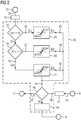
- FIG. 2 the construction of a tap selection controller 30 is shown in block diagram form; each of the two selectors 16 and 17, respectively FIG. 1 can be executed as it is in the FIG. 2 shown and explained in more detail below.
- the tap selector 30 is detected via a voltage detector 31 according to, for example, the voltage detecting means 20 and 21, respectively FIG. 1 connected to the common coupling point 10, which here differs from the FIG. 1 is shown only schematically.
- the voltage detection device 31 not only the voltage at the common coupling point 10 is measured, but also a digitization of the detected values, which are supplied in this form to a first selection module 32 of the tapping selection controller 30, takes place.
- This first selection module 32 generates at its output 33 a yes signal S1j when the voltage Uk at the common coupling point 10 is greater than 1.05, in which case a normalized voltage is used, which is related to the nominal voltage.
- the signal S1j is formed when the voltage Uk at the common coupling point 10 is greater than 1.05.
- a downstream range selector 34 is driven, with which a certain range of the voltage Us on the busbar 6 and 7 (see. FIG. 1 ) is given.
- the range is defined by the voltage Ukmin and Ukmax1, where both Ukmax and Ukmin1 are relatively high values. At the output 35 of the range selector 34, therefore, a signal occurs when the voltage Uk at the common coupling point 10 satisfies the condition mentioned above, ie is relatively large.
- a signal S1n is formed and it is checked in a subsequent further selection component 36 whether the normalized voltage greater than 1 is exemplary but less than 1.05. If this is the case, then a signal S2j is generated at an output 37 of the further selection module 36 and thus a downstream further area selector 38 is applied which covers a range of the voltage Uk at the busbar 6 or 7 between the values Ukmax21 and Ukmin2. In this case, an output signal B1j is formed at the output 39 of the further range selector 38.
- a signal S 2n is generated at its output, which signal acts on an additional range selector 41; this additional area selector 41 is defined for a voltage range Ukmin3 to Ukmax 3 of the voltage at the busbar 6 and 7, respectively.
- a signal B3j is output at an output 42 of the additional area selector 41.
- the outputs 35, 39 and 42 of the three range selectors 34, 38 and 41 are jointly connected to an input 44 of a decision block 45, which is connected to a further input 46 via the further voltage detection means 47 corresponding to the further voltage detection means 24th according to FIG. 1 is connected to the busbar 6, which in turn is shown here only schematically.
- the decision block 45 it is constantly checked whether the voltage Us at the bus bar 6 or 7 is within the range specified by the range selectors 34, 38 and 41. If this is not the case, then an output signal An is generated, with which the setting of not shown taps of the feed transformer 14 or 17 is changed in a tap adjuster 48.
- the result is a voltage Us at the busbar 6, due to the wind generators 3 and 5 are set so that at the common coupling point 10, a predetermined voltage is produced, which corresponds to the specifications of the operator of the AC voltage network 11, as will be explained in detail below.
- a characteristic curve 50 includes regions which lie both to the right and to the left of the power factor 1. In this case, the areas lying to the left of the power factor 1 indicate the state in which the wind generators 3 and 4 (cf. Fig. 1 ) while the right side of the power factor 1 describes the cases in which the wind generators 3 and 4 are overexcited.
- the characteristic curve 50 represents a characteristic curve, which stands by way of example for a characteristic curve predefined by an operator of the AC voltage network 11. The wind generators must therefore be operated so that the voltage Uk at the common coupling point 10 as a function of the supplied reactive power results in an operating point which lies within the characteristic 50.
- FIG. 4 Essential for the understanding of the method according to the invention or the mode of action of the arrangement according to the invention is the FIG. 4 , in which in a diagram - normalized voltage Ukn at the busbar 6 and 7 above the delivered normalized power Qn (the area to the left of "0" indicates the under-excited state and the area to the right of "0" the over-excited state of the wind generators) - two characteristics 51 and 52 are shown for two different types of wind generators. It can be seen that each of the two characteristic curves 51 and 52 has regions in which the output of inductive or capacitive reactive power over the normalized power Qn is restricted.
- the characteristic curve 51 it follows that a capacitive reactive power output substantially only in the normalized voltage range above about 1.05 and a capacitive and inductive reactive power Qn between the normalized voltage values Ukn and 1.05 is possible, if both characteristics 51 and 52 taken into account. Below the normalized voltage Ukn of 1, taking into account both characteristics 51 and 52, only inductive reactive power can be generated.
- the invention makes use of this finding by using the area selectors 35, 38 and 41 described above (cf. FIG. 2 ) the voltage ranges of the voltage Us at the busbars 6 and 7, respectively, which is required in view of the provision of a prescribed quality of the power supply at the common coupling point 10, are selected. That's how it shows FIG. 4 It is very clear that with normalized voltages Usn greater than 1.05, only capacitive reactive power can be generated at the busbar 6 according to characteristic curve 51. In the range between 1 and 1.05 of the normalized voltage Ukn, the extent of the generation of capacitive reactive power is already reduced, while for values of the normalized voltage Ukn below 1, primarily inductive reactive power can be generated. By regulating or adjusting the voltage Uk at the busbars 6 and 7, respectively, an excitation state of the wind generators can thus be established which determines the reactive power requirements at the common coupling point 10 fulfilled, without the need for reactive power compensation systems must be provided.
Landscapes
- Engineering & Computer Science (AREA)
- Power Engineering (AREA)
- Supply And Distribution Of Alternating Current (AREA)
Description
- Verfahren und Anordnung zum Einspeisen von elektrischer Leistung aus einer Windenergieanlage in ein Wechselspannungsnetz Es ist bekannt, mittels einer Windenergieanlage elektrische Leistung zu gewinnen und diese Leistung über eine Energieübertragungsstrecke in ein Wechselspannungs-Energieversorgungsnetz einzuspeisen. Dabei kann es sich bei der Windenergieanlage um einen einzigen Windgenerator oder um mehrere Windgeneratoren handeln, die dann einen sog. Windpark bilden. Die Leistungsübergabe an das Wechselspannungsnetz erfolgt an einem gemeinsamen Kopplungspunkt, der auch als PCC (point of common coupling) bezeichnet wird. Eine derartige Anordnung wird in der
DE102008048258 behandelt. Dieses Dokument offenbart, im Sinne des Wortlauts des Anspruchs 1, ein Verfahren zum Einspeisen von elektrischer Leistung aus einer Windenergieanlage über eine Energieübertragungsstrecke in ein Wechselspannungsnetz an einem gemeinsamen Kopplungspunkt von Energieübertragungsstrecke und Wechselspannungsnetz, bei dem - die Spannung am Ausgang der Windenergieanlage erfasst und dem Anzapfungen-Auswahlregler zugeführt wird und - in Abhängigkeit von der Höhe der erfassten Spannung von dem Anzapfungen-Auswahlregler, bei einem in der Energieübertragungsstrecke angeordneten und mit Anzapfungen versehenen Einspeisetransformator Anzapfungen derart belegt werden, dass am Ausgang der Windenergieanlage eine Spannung auftritt, die zu einer vorgegebenen Spannung am gemeinsamen Kopplungspunkt führt. - Hinsichtlich der Einspeisung von elektrischer Leistung in einen Kopplungspunkt werden von dem jeweiligen Betreiber des Wechselspannungsnetzes Anforderungen bezüglich der Qualität der eingespeisten elektrischen Leistung gestellt, die seitens der Windenergieanlage eingehalten werden müssen. Dazu gehört unter anderem, dass von der Windenergieanlage der Kopplungspunkt mit Blindleistung versorgt werden muss.
Diese Anforderungen sind bisher mittels Blindleistungskompensationsanlagen erfüllt worden, die zuschaltbare Induktivitäten und Kapazitäten aufweisen und sehr aufwändig sind.
Der Erfindung liegt die Aufgabe zugrunde, ein Verfahren zum Einspeisen von elektrischer Leistung aus einer Windenergieanlage über eine Energieübertragungsstrecke in ein Wechselspannungsnetz an einem gemeinsamen Kopplungspunkt anzugeben, mit dem sich bei der Einspeisung von elektrischer Leistung mit vergleichsweise geringem Aufwand die jeweils angeforderte Blindleistung an dem Kopplungspunkt zur Verfügung stellen lässt. Die vorliegende Erfindung löst die Aufgabe durch ein Verfahren und eine Anordnung entsprechend der unabhängigen Ansprüche. Weitere erfindungsgemäße Ausgestaltungen werden durch die abhängigen Ansprüche offenbart. - Die Lösung dieser Aufgabe wird in einem Verfahren zum Einspeisen von Leistung aus einer Windenergieanlage über eine Energieübertragungsstrecke in ein Wechselspannungsnetz an einem gemeinsamen Kopplungspunkt von Energieübertragungsstrecke und Wechselspannungsnetz gesehen, bei dem die Spannung am Kopplungspunkt erfasst und einem Anzapfungen-Auswahlregler zugeführt wird; außerdem wird die Spannung am Ausgang der Windenergieanlage erfasst und dem Anzapfungen-Auswahlregler zugeführt wird; in Abhängigkeit von der Höhe der erfassten Spannungen werden von dem Anzapfungen-Auswahlregler bei einem in der Energieübertragungsstrecke angeordneten und mit Anzapfungen versehenen Einspeisetransformator Anzapfungen derart belegt, dass am Ausgang der Windenergieanlage eine Spannung auftritt, die zu einer vorgegebenen Spannung am gemeinsamen Kopplungspunkt führt.
- Der wesentliche Vorteil des Verfahrens besteht darin, dass es - je nach Blindleistungsanforderungen - ohne eine Blindleistungskompensationsanlage oder mit einer relativ kleinen und damit wenig aufwändigen Blindleistungskompensationsanlage auskommt.
Die Verarbeitung der erfassten Spannung am Kopplungspunkt in dem Anzapfungen-Auswahlregler kann bei dem Verfahren in verschiedener Weise erfolgen. Als besonders vorteilhaft wird es zur Erzielung einer stabilen Regelung angesehen, wenn die am Kopplungspunkt erfasste Spannung dahingehend überprüft wird, in welchem von mehreren vorgegebenen Spannungsbereichen sie liegt, und entsprechend dem Ergebnis dieser Prüfung mittels eines Bereichsselektors von mehreren jedem Spannungsbereich der Spannung am Kopplungspunkt zugeordneten Bereichsselektoren für die Ausgangsspannung an der Windenergieanlage ein Anzapfungen-Auswahlregler so beaufschlagt wird, dass die Spannung am Ausgang der Windenergieanlage im Spannungsbereich des jeweiligen Bereichsselektors liegt.
Als besonders vorteilhaft wird es angesehen, wenn Bereichsselektoren mit Spannungsbereichen verwendet werden, die aneinander angrenzend sämtlich innerhalb einer die Abhängigkeit der Spannung am Ausgang der Windenergieanlage von ihrer Blindleistung beschreibenden Kennlinie liegen. Diese Kennlinie wird vom jeweiligen Betreiber des Wechselspannungsnetzes individuell für jeden Kopplungspunkt vorgegeben; durch die oben angegebene Auswahl der Bereichsselektoren ist eine leichte Anpassung an die verschiedenen Gegebenheiten möglich. Vorteilhafterweise werden drei Bereichsselektoren verwendet, weil diese Anzahl für die meisten Anwendungsfälle ausreichend erscheint.
Der Erfindung liegt ferner die Aufgabe zugrunde, eine Anordnung zum Einspeisen von elektrischer Leistung aus einer Windenergieanlage über eine Energieübertragungsstrecke in ein Wechselspannungsnetz an einem gemeinsamen Kopplungspunkt vorzuschlagen, mit der sich mit relativ geringem Aufwand die jeweils an dem Kopplungspunkt zur Verfügung zustellende Blindleistung erzeugen lässt. - Zur Lösung dieser Aufgabe dient eine Anordnung zum Einspeisen von elektrischer Leistung aus einer Windenergieanlage über eine Energieübertragungsstrecke in ein Wechselspannungsnetz an einem gemeinsamen Kopplungspunkt von Energieübertragungsstrecke und Wechselspannungsnetz, bei der ein Spannungseingang eines Anzapfungen-Auswahlreglers über eine Spannungserfassungseinrichtung mit dem gemeinsamen Kopplungspunkt verbunden ist und ein weiterer Spannungseingang des Anzapfungen-Auswahlreglers über eine weitere Spannungserfassungseinrichtung an den Ausgang der Windenergieanlage angeschlossen ist; ein Ausgang des Anzapfungen-Auswahlreglers ist mit einem in der Energieübertragungsstrecke angeordneten und mit Anzapfungen versehenen Einspeisetransformator verbunden, dessen Anzapfungen in Abhängigkeit von der Höhe der erfassten Spannungen von dem Anzapfungen-Auswahlregler derart belegt werden, dass am Ausgang der Windenergieanlage eine Spannung auftritt, die zu einer vorgegebenen Spannung am gemeinsamen Kopplungspunkt führt.
Eine solche Anordnung zeichnet sich vor allem dadurch aus, dass sie ohne eine Blindleistungskompensationsanlage auskommt oder nur eine kleine Blindleistungskompensationsanlage benötigt, weil allein durch Regelungsmaßnahmen die jeweils angeforderte Blindleistung erzeugbar ist. - In einer vorteilhaften Ausgestaltung weist bei der Anordnung der Anzapfungen-Auswahlregler an die eine Spannungserfassungseinrichtung angeschlossene Auswahlbausteine auf, die die am Kopplungspunkt erfasste Spannung dahingehend überprüfen, in welchem von mehreren vorgegebenen Spannungsbereichen sie liegt; den Auswahlbausteinen sind Bereichsselektoren für die Ausgangsspannung an der Windenergieanlage nachgeordnet, und den Bereichsselektoren ist ein Anzapfungen-Einstellregler nachgeordnet, der entsprechend dem Ergebnis der Prüfung in den Auswahlbausteinen über die Bereichsselektoren so beaufschlagt wird, dass die Spannung am Ausgang der Windenergieanlage im Spannungsbereich des jeweiligen Bereichsselektors liegt.
- Bei der Anordnung decken Bereichsselektoren Spannungsbereiche ab, die aneinander angrenzend sämtlich innerhalb einer die Abhängigkeit der Spannung am Ausgang der Windenergieanlage von ihrer Blindleistung beschreibenden Kennlinie liegen, womit - wie oben bereits im Zusammenhang mit der Erläuterung des Verfahrens angegeben - eine leichte Anpassung an verschiedene Vorgaben der Betreiber von Wechselspannungsnetzen ermöglicht ist.
- Mit Vorteil sind bei der Anordnung drei Bereichsselektoren vorhanden.
Zur weiteren Erläuterung der Erfindung sind in -
Fig. 1 ein Ausführungsbeispiel der erfindungsgemäßen Anordnung mit einem Anzapfungen-Auswahlregler, in -
Fig. 2 ein Blockschaltbild des Anzapfungen-Auswahlreglers gemäßFig. 1 , in -
Fig. 3 eine beispielhafte Kennlinie für die Blindleistungsanforderung an einem Kopplungspunkt und in -
Fig. 4 Kennlinien von zwei Windgeneratoren dargestellt. - Wie die
Figur 1 ferner zeigt, ist jedem der Einspeisetransformatoren 14 bzw. 15 ein Anzapfungen-Auswahlregler 16 bzw. 17 zugeordnet. Jeder der beiden Anzapfungen-Auswahlregler 16 bzw. 17 ist mit seinem einen Eingang 18 bzw. 19 über eine Spannungserfassungseinrichtung 20 bzw. 21 beliebiger Ausführung mit dem gemeinsamen Kopplungspunkt 10 verbunden, der auf einer Spannung Uk von beispielsweise 155 kV liegt; jeweils ein weiterer Eingang 22 bzw. 23 der Anzapfungen-Auswahlregler 16 bzw. 17 ist über jeweils eine weitere Spannungserfassungseinrichtung 24 bzw. 25 beliebiger Ausführung mit den Sammelschienen 6 bzw. 7 verbunden. Jeder der Anzapfungen-Auswahlregler 16 bzw. 17 ist mit seinem Ausgang 26 bzw. 27 mit einer nicht näher dargestellten Einstelleinrichtung für die Anzapfungen des jeweiligen Einspeisetransformators 14 bzw. 15 verbunden. - Der
Figur 1 ist ebenfalls zu entnehmen, dass die eine Sammelschiene 6 über eine Leitung auch mit dem Einspeisetransformator 15 und die andere Sammelschiene 7 über eine weitere Leitung auch mit dem Einspeisetransformator 15 verbunden ist. - In der
Figur 2 ist der Aufbau eines Anzapfungen-Auswahlreglers 30 in Form eines Blockschaltbildes gezeigt; jeder der beiden Auswahl-Regler 16 bzw. 17 gemäßFigur 1 kann so ausgeführt sein, wie es in derFigur 2 gezeigt und nachfolgend näher erläutert ist. - Wie die
Figur 2 im Einzelnen zeigt, ist der Anzapfungen-Auswahlregler 30 über eine Spannungserfassungseinrichtung 31 beispielsweise gemäß der Spannungserfassungseinrichtung 20 bzw. 21 gemäßFigur 1 mit dem gemeinsamen Kopplungspunkt 10 verbunden, der hier in Abweichung von derFigur 1 nur schematisch dargestellt ist. - In der Spannungserfassungseinrichtung 31 wird nicht nur die Spannung am gemeinsamen Kopplungspunkt 10 gemessen, sondern es erfolgt auch eine Digitalisierung der erfassten Werte, die in dieser Form einem ersten Auswahlbaustein 32 des Anzapfungen-Auswahlreglers 30 zugeführt werden. Dieser erste Auswahlbaustein 32 erzeugt an seinem Ausgang 33 ein Ja-Signal S1j, wenn die Spannung Uk an dem gemeinsamen Kopplungspunkt 10 größer als 1,05 beispielhaft ist, wobei hierbei eine normierte Spannung verwendet wird, die auf die Nennspannung bezogen ist. Es wird also das Signal S1j gebildet, wenn die Spannung Uk am gemeinsamen Kopplungspunkt 10 größer als 1,05 ist. In diesem Falle wird ein nachgeordneter Bereichsselektor 34 angesteuert, mit dem ein bestimmter Bereich der Spannung Us an der Sammelschiene 6 bzw. 7 (vgl.
Figur 1 ) vorgegeben wird. Der Bereich ist durch die Spannung Ukmin und Ukmax1 definiert, wobei sowohl Ukmax als auch Ukmin1 relativ hohe Werte sind. Am Ausgang 35 des Bereichsselektors 34 tritt also ein Signal auf, wenn die Spannung Uk am gemeinsamen Kopplungspunkt 10 die eingangs genannte Bedingung erfüllt, also relativ groß ist. - Wird im Auswahlbaustein 32 festgestellt, dass die Spannung Uk am gemeinsamen Kopplungspunkt 10 der für den einen Auswahlbaustein 32 definierten Bedingungen nicht genügt, dann wird ein Signal S1n gebildet und es wird in einem nachgeordneten weiteren Auswahlbaustein 36 geprüft, ob die normierte Spannung größer als 1 beispielhaft, aber kleiner als 1,05 ist. Ist dies der Fall, dann wird an einem Ausgang 37 des weiteren Auswahlbausteins 36 ein Signal S2j erzeugt und damit ein nachgeordneter weiterer Bereichsselektor 38 beaufschlagt, der einen Bereich der Spannung Uk an der Sammelschiene 6 bzw. 7 zwischen den Werten Ukmax21 und Ukmin2 abdeckt. Es wird in diesem Falle ein Ausgangssignal B1j am Ausgang 39 des weiteren Bereichsselektors 38 gebildet.
- Stellt der weitere Auswahlbaustein 36 fest, dass der für ihn definierte Spannungsbereich der Spannung Uk am gemeinsamen Kopplungspunkt 10 nicht eingehalten ist, dann wird an seinem Ausgang 40 ein Signal S2n erzeugt, das einen zusätzlichen Bereichsselektor 41 beaufschlagt; dieser zusätzliche Bereichsselektor 41 ist für einen Spannungsbereich Ukmin3 bis Ukmax 3 der Spannung an der Sammelschiene 6 bzw. 7 definiert. Es wird in diesem Falle an einem Ausgang 42 des zusätzlichen Bereichsselektors 41 ein Signal B3j abgegeben.
- Der
Figur 2 lässt sich ferner entnehmen, dass die Ausgänge 35, 39 und 42 der drei Bereichsselektoren 34, 38 und 41 gemeinsam an einen Eingang 44 eines Entscheider-Bausteins 45 geführt sind, der mit einem weiteren Eingang 46 über die weitere Spannungserfassungseinrichtung 47 entsprechend der weiteren Spannungserfassungseinrichtung 24 gemäßFigur 1 mit der Sammelschiene 6 verbunden ist, die hier wiederum nur schematisch dargestellt ist. In dem Entscheider-Baustein 45 wird ständig überprüft, ob die Spannung Us an der Sammelschiene 6 bzw. 7 innerhalb des Bereichs liegt, der mit den Bereichsselektoren 34, 38 und 41 vorgegeben ist. Ist das nicht der Fall, dann wird ein Ausgangssignal An erzeugt, mit dem in einem Anzapfungen-Einsteller 48 die Einstellung von nicht gezeigten Anzapfungen des Einspeisetransformators 14 bzw. 17 verändert wird. Das Ergebnis ist eine Spannung Us an der Sammelschiene 6, aufgrund der die Windgeneratoren 3 bzw. 5 so eingestellt werden, dass am gemeinsamen Kopplungspunkt 10 eine vorgegebene Spannung entsteht, die den Vorgaben des Betreibers des Wechselspannungsnetzes 11 entspricht, wie nachfolgend noch im Einzelnen erläutert wird. - Kommt der Entscheider-Baustein 45 zu dem Ergebnis, dass die Spannung Us an der Sammelschiene 6 in dem jeweils mittels der Bereichsselektoren 34, 38, und 41 ausgewählten Spannungsbereich liegt, dann wird an seinem Ausgang 47 ein Signal Aj erzeugt, auf das hin die Spannung Uk an dem gemeinsamen Kopplungspunkt 10 beibehalten wird.
- In
Figur 3 ist ein Diagramm gezeigt, in dem der Leistungsfaktor P über der Spannung Uk an dem gemeinsamen Kopplungspunkt 10 aufgetragen ist. Eine Kennlinie 50 umfasst Bereiche, die sowohl rechts als auch links vom Leistungsfaktor 1 liegen. Dabei geben die links von dem Leistungsfaktor 1 liegenden Bereiche den Zustand an, in dem die Windgeneratoren 3 bzw. 4 (vgl.Fig. 1 ) untererregt sind, während der rechts von dem Leistungsfaktor 1 liegende Bereich die Fälle beschreibt, in denen die Windgeneratoren 3 bzw. 4 übererregt sind. Die Kennlinie 50 stellt dabei eine Kennlinie dar, die beispielhaft für eine von einem Betreiber des Wechselspannungsnetzes 11 vorgegebene Kennlinie steht. Die Windgeneratoren müssen also so betrieben werden, dass die Spannung Uk am gemeinsamen Kopplungspunkt 10 in Abhängigkeit von der gelieferten Blindleistung einen Arbeitspunkt ergibt, der innerhalb der Kennlinie 50 liegt. - Wesentlich für das Verständnis des erfindungsgemäßen Verfahrens bzw. der Wirkungsweise der erfindungsgemäßen Anordnung ist die
Figur 4 , in der in einem Diagramm - normierte Spannung Ukn an der Sammelschiene 6 bzw. 7 über der abgegebenen normierten Leistung Qn (der Bereich links von "0" bezeichnet den untererregten Zustand und der Bereich rechts von "0" den übererregten Zustand der Windgeneratoren) - zwei Kennlinien 51 und 52 für zwei verschiedene Typen von Windgeneratoren dargestellt sind. Es ist zu erkennen, dass jede der beiden Kennlinien 51 bzw. 52 Bereiche aufweist, in denen die Abgabe induktiver bzw. kapazitiver Blindleistung über der normierten Leistung Qn eingeschränkt ist. Betrachtet man beispielsweise die Kennlinie 51, dann ergibt sich, dass eine kapazitive Blindleistungsabgabe im Wesentlichen nur im normierten Spannungsbereich oberhalb von etwa 1,05 und eine kapazitive und induktive Blindleistung Qn zwischen den normierten Spannungswerten Ukn und 1.05 möglich ist, wenn man beide Kennlinien 51 und 52 berücksichtigt. Unterhalb der normierten Spannung Ukn von 1 ist unter Berücksichtigung beider Kennlinien 51 und 52 nur induktive Blindleistung erzeugbar. - Die Erfindung macht sich diese Erkenntnis zu Nutze, indem mittels der oben beschriebenen Bereichsselektoren 35, 38 und 41 (vgl.
Figur 2 ) die Spannungsbereiche der Spannung Us an der Sammelschiene 6 bzw. 7 jeweils ausgewählt werden, die im Hinblick auf die zur Verfügungstellung einer vorgeschriebene Qualität der Leistungszufuhr am gemeinsamen Kopplungspunkt 10 erforderlich ist. So zeigt dieFigur 4 sehr deutlich, dass sich mit normierten Spannungen Usn größer als 1,05 an der Sammelschiene 6 gemäß Kennlinie 51 nur kapazitive Blindleistung erzeugen lässt. Im Bereich zwischen 1 und 1,05 der normierten Spannung Ukn ist das Ausmaß der Erzeugung kapazitiver Blindleistung schon verringert, während sich bei Werten der normierten Spannung Ukn unterhalb 1 primär induktive Blindleistung erzeugen lässt. Durch Regelung bzw. Einstellung der Spannung Uk an den Sammelschienen 6 bzw. 7 lässt sich also jeweils ein Erregungszustand der Windgeneratoren herstellen, der die Blindleistungsanforderungen am gemeinsamen Kopplungspunkt 10 erfüllt, ohne dass dafür Blindleistungskompensationsanlagen vorgesehen sein müssen. - Wenn in besonderen Fällen diese Regelung nicht ausreicht, dann müssen zwar auch Blindleistungskompensationsanlagen zum Einsatz gelangen, jedoch können diese viel kleiner und damit mit erheblich weniger Aufwand hergestellt werden, als dies ohne Einsatz der Erfindung möglich ist.
Claims (6)
- Verfahren zum Einspeisen von elektrischer Leistung aus einer Windenergieanlage (2,3) über eine Energieübertragungsstrecke (8, 9) in ein Wechselspannungsnetz (11) an einem gemeinsamen Kopplungspunkt (10) von Energieübertragungsstrecke (8, 9) und Wechselspannungsnetz (11), bei dem• die Spannung (Uk) am Kopplungspunkt (10) erfasst und einem Anzapfungen-Auswahlregler (16, 17) zugeführt wird,• die Spannung (Us) am Ausgang der Windenergieanlage (2, 3) erfasst und dem Anzapfungen-Auswahlregler (16, 17) zugeführt wird und• in Abhängigkeit von der Höhe der erfassten Spannungen (Uk, Us) von dem Anzapfungen-Auswahlregler (16, 17) bei einem in der Energieübertragungsstrecke (8, 9) angeordneten und mit Anzapfungen versehenen Einspeisetransformator (14, 15) Anzapfungen derart belegt werden, dass am Ausgang der Windenergieanlage (2, 3) eine Spannung (Us) auftritt, die zu einer vorgegebenen Spannung (Uk) am gemeinsamen Kopplungspunkt (10) führt,wobei• die am Kopplungspunkt (10) erfasste Spannung (Uk) dahingehend überprüft wird, in welchem von mehreren vorgegebenen Spannungsbereichen (Ukmin1 - Ukmax1, Ukmin2 - Ukmax2, Ukmin3 - Ukmax3) sie liegt, und• entsprechend dem Ergebnis dieser Prüfung mittels eines Bereichsselektors (34, 38, 41) von mehreren jedem Spannungsbereich (Ukmin1-Ukmax1, Ukmin2-Ukmax2, Ukmin3-Ukmax3) der Spannung am Kopplungspunkt (10) zugeordneten Bereichsselektoren (34, 38, 41) für die Ausgangsspannung (Us) an der Windenergieanlage (2, 3) der Anzapfungen-Auswahlregler (14, 15) so beaufschlagt wird, dass die Spannung (Uk) am Ausgang der Windenergieanlage (2, 3) im Spannungsbereich (Ukmin1-Ukmax1, Ukmin2-Ukmax2, Ukmin3-Ukmax3) des jeweiligen Bereichsselektors (34, 38, 41) liegt.
- Verfahren nach Anspruch 1,
dadurch gekennzeichnet, dass• Bereichsselektoren (34, 38, 41) mit Spannungsbereichen (Ukmin1-Ukmax1, Ukmin2-Ukmax2, Ukmin3-Ukmax3) verwendet werden, die aneinander angrenzend sämtlich innerhalb einer die Abhängigkeit der Spannung (Us) am Ausgang der Windenergieanlage (2, 3) von ihrer Blindleistung (Q) beschreibenden Kennlinie (51, 52) liegen. - Verfahren nach Anspruch 1 oder 2,
dadurch gekennzeichnet, dass• drei Bereichsselektoren (34, 38, 41) verwendet werden. - Anordnung (1) zum Einspeisen von elektrischer Leistung aus einer Windenergieanlage (2, 3) über eine Energieübertragungsstrecke (8, 9) in ein Wechselspannungsnetz (11) an einem gemeinsamen Kopplungspunkt (10) von Energieübertragungsstrecke (8, 9) und Wechselspannungsnetz (11), bei der• ein Spannungseingang (18, 19) eines Anzapfungen-Auswahlreglers (16, 17) über eine Spannungserfassungseinrichtung (20, 21) mit dem gemeinsamen Kopplungspunkt (10) verbunden ist,• ein weiterer Spannungseingang (22, 23) des Anzapfungen-Auswahlreglers (16, 17) über eine weitere Spannungserfassungseinrichtung (22, 23) an den Ausgang (6, 7) der Windenergieanlage (2, 3) angeschlossen ist,• ein Ausgang (26, 27) des Anzapfungen-Auswahlreglers (16, 17) mit einem in der Energieübertragungsstrecke (8, 9) angeordneten und mit Anzapfungen versehenen Einspeisetransformator (14, 15) verbunden ist, dessen Anzapfungen in Abhängigkeit von der Höhe der erfassten Spannungen (Uk, Us) von dem Anzapfungen-Auswahlregler (16, 17) derart belegt werden, dass am Ausgang der Windenergieanlage (2, 3) eine Spannung (Us) auftritt, die zu einer vorgegebenen Spannung (Uk) am gemeinsamen Kopplungspunkt (10) führt,• der Anzapfungen-Auswahlregler (16, 17) an die eine Spannungserfassungseinrichtung (20, 21) angeschlossene Auswahlbausteine (32, 36) aufweist, die die am Kopplungspunkt (10) erfasste Spannung (Uk) dahingehend überprüfen, in welchem von mehreren vorgegebenen Spannungsbereichen (Ukmin1-Ukmax1, Ukmin2-Ukmax2, Ukmin3-Ukmax3) sie liegt, und• den Auswahlbausteinen (32, 36) Bereichsselektoren (34, 38, 41) für die Ausgangsspannung (Us) an der Windenergieanlage (2, 3) nachgeordnet sind, und• den Bereichsselektoren (34, 38, 41) ein Anzapfungen-Einsteller (48) nachgeordnet ist, der entsprechend dem Ergebnis der Prüfung in den Auswahlbausteinen (32, 36) über die Bereichsselektoren (34, 38, 41) so beaufschlagt wird, dass die Spannung (Us) am Ausgang der Windenergieanlage (2, 3) im Spannungsbereich (Ukmin1-Ukmax1, Ukmin2-Ukmax2, Ukmin3-Ukmax3) des jeweiligen Bereichsselektors (34, 38, 41) liegt.
- Anordnung nach Anspruch 4,
dadurch gekennzeichnet, dass• die Bereichsselektoren (34, 38, 41) Spannungsbereiche (Ukmin1-Ukmax1, Ukmin2-Ukmax2, Ukmin3-Ukmax3) abdecken, die aneinander angrenzend sämtlich innerhalb einer die Abhängigkeit der Spannung (Us) am Ausgang der Windenergieanlage (2, 3) von ihrer Blindleistung (Qn) beschreibenden Kennlinie liegen. - Anordnung nach Anspruch 4 oder 5,
dadurch gekennzeichnet, dass• drei Bereichsselektoren (34, 38, 41) vorhanden sind.
Applications Claiming Priority (1)
| Application Number | Priority Date | Filing Date | Title |
|---|---|---|---|
| PCT/EP2011/056658 WO2012146277A1 (de) | 2011-04-27 | 2011-04-27 | Verfahren und anordnung zum einspeisen von elektrischer leistung aus einer windenergieanlage in ein wechselspannungsnetz |
Publications (2)
| Publication Number | Publication Date |
|---|---|
| EP2689511A1 EP2689511A1 (de) | 2014-01-29 |
| EP2689511B1 true EP2689511B1 (de) | 2017-05-31 |
Family
ID=44121442
Family Applications (1)
| Application Number | Title | Priority Date | Filing Date |
|---|---|---|---|
| EP11717579.4A Active EP2689511B1 (de) | 2011-04-27 | 2011-04-27 | Verfahren und anordnung zum einspeisen von elektrischer leistung aus einer windenergieanlage in ein wechselspannungsnetz |
Country Status (3)
| Country | Link |
|---|---|
| EP (1) | EP2689511B1 (de) |
| ES (1) | ES2638899T3 (de) |
| WO (1) | WO2012146277A1 (de) |
Family Cites Families (3)
| Publication number | Priority date | Publication date | Assignee | Title |
|---|---|---|---|---|
| DE102008018748A1 (de) * | 2008-04-14 | 2009-10-15 | Repower Systems Ag | Windenergieanlage mit Anschlussschutzeinrichtung |
| DE102008048258B4 (de) * | 2008-09-22 | 2016-12-08 | Senvion Gmbh | Windpark und Verfahren zum Betreiben eines Windparks |
| ES2571222T3 (es) * | 2009-04-17 | 2016-05-24 | Vestas Wind Sys As | Parque eólico, procedimiento de corrección de desequilibrios de tensión, y turbina eólica |
-
2011
- 2011-04-27 WO PCT/EP2011/056658 patent/WO2012146277A1/de not_active Ceased
- 2011-04-27 ES ES11717579.4T patent/ES2638899T3/es active Active
- 2011-04-27 EP EP11717579.4A patent/EP2689511B1/de active Active
Also Published As
| Publication number | Publication date |
|---|---|
| EP2689511A1 (de) | 2014-01-29 |
| ES2638899T3 (es) | 2017-10-24 |
| WO2012146277A1 (de) | 2012-11-01 |
Similar Documents
| Publication | Publication Date | Title |
|---|---|---|
| EP2872777B1 (de) | Verfahren zum steuern eines elektrischen erzeugers | |
| EP2244348B1 (de) | Windpark mit mehreren Windenergieanlagen sowie Verfahren zur Regelung der Einspeisung von einem Windpark | |
| DE102012212777A1 (de) | Verfahren zum Steuern eines Windparks | |
| EP3646430A1 (de) | Verfahren zum betrieb eines inselnetzes und inselnetz | |
| WO2010091786A2 (de) | Photovoltaikanlage zur dreiphasigen einspeisung in ein elektrisches energieversorgungsnetz | |
| DE3225285A1 (de) | Verfahren zum betrieb einer hochspannungs-gleichstromuebertragungsanlage mit beliebig vielen umformerstationen | |
| EP2864631B1 (de) | Windpark mit mehreren netzeinspeisepunkten | |
| EP3042428B1 (de) | Vorrichtung und verfahren zur steuerung der stabilität eines ortsnetzes mit einem regelbaren ortsnetztransformator | |
| DE102008048258A1 (de) | Windpark und Verfahren zum Betreiben eines Windparks | |
| EP3097622B1 (de) | Windparkregelung mit verbessertem sollwertsprungverhalten | |
| DE102019129413B4 (de) | Kompensationsvorrichtung für Ableitströme | |
| DE102014016664A1 (de) | Verfahren zum Betreiben einer Windenenergieanlage mit komplexer Umrichtersteuerung und Vorrichtung hierfür | |
| EP2751897B1 (de) | Schnelle spannungsregelung | |
| DE102012100673A1 (de) | Vorrichtung zur elektrischen Energieeinspeisung aus einer dezentralen Eigenerzeugeranlage in ein Stromnetz | |
| EP3092697B1 (de) | Verfahren und regeleinrichtung zum regeln einer betriebsfrequenz einer energiequelle in einem wechselspannungsnetz | |
| DE112022002486T5 (de) | Einstellung der umrichterklemmenspannung in leistungssystem | |
| DE102016203123B4 (de) | Vorrichtung und Verfahren zur Regelung eines Wechselrichters | |
| EP3097624B1 (de) | Wechselrichter, insbesondere als teil eines energieerzeugungsverbundes, und verfahren | |
| EP3311481B1 (de) | Verfahren zur regelung eines selbstgeführten umrichters, selbstgeführter umrichter sowie anordnung zur übertragung elektrischer leistung | |
| WO2012146277A1 (de) | Verfahren und anordnung zum einspeisen von elektrischer leistung aus einer windenergieanlage in ein wechselspannungsnetz | |
| EP3548738B1 (de) | Verfahren und vorrichtung zum regeln von einem leistungswert eines offshore-windenergiesystems | |
| DE102014014966A1 (de) | Elektrisches Verteilnetz sowie Verfahren zum Betreiben eines elektrischen Verteilnetzes | |
| DE102011014468B4 (de) | Phasenselektives VAr - Management | |
| DE602429C (de) | Elektrischer Mehrmotorenantrieb fuer Papiermaschinen | |
| WO2024012680A1 (de) | Fehlerbehandlung bei einem terminal eines multiterminal-hochspannungs-gleichstrom-übertragungssystem |
Legal Events
| Date | Code | Title | Description |
|---|---|---|---|
| PUAI | Public reference made under article 153(3) epc to a published international application that has entered the european phase |
Free format text: ORIGINAL CODE: 0009012 |
|
| 17P | Request for examination filed |
Effective date: 20131022 |
|
| AK | Designated contracting states |
Kind code of ref document: A1 Designated state(s): AL AT BE BG CH CY CZ DE DK EE ES FI FR GB GR HR HU IE IS IT LI LT LU LV MC MK MT NL NO PL PT RO RS SE SI SK SM TR |
|
| DAX | Request for extension of the european patent (deleted) | ||
| RIC1 | Information provided on ipc code assigned before grant |
Ipc: H02J 3/18 20060101AFI20160812BHEP Ipc: H02J 3/38 20060101ALI20160812BHEP |
|
| GRAP | Despatch of communication of intention to grant a patent |
Free format text: ORIGINAL CODE: EPIDOSNIGR1 |
|
| GRAJ | Information related to disapproval of communication of intention to grant by the applicant or resumption of examination proceedings by the epo deleted |
Free format text: ORIGINAL CODE: EPIDOSDIGR1 |
|
| INTG | Intention to grant announced |
Effective date: 20160930 |
|
| INTC | Intention to grant announced (deleted) | ||
| GRAP | Despatch of communication of intention to grant a patent |
Free format text: ORIGINAL CODE: EPIDOSNIGR1 |
|
| INTG | Intention to grant announced |
Effective date: 20161208 |
|
| GRAS | Grant fee paid |
Free format text: ORIGINAL CODE: EPIDOSNIGR3 |
|
| GRAA | (expected) grant |
Free format text: ORIGINAL CODE: 0009210 |
|
| AK | Designated contracting states |
Kind code of ref document: B1 Designated state(s): AL AT BE BG CH CY CZ DE DK EE ES FI FR GB GR HR HU IE IS IT LI LT LU LV MC MK MT NL NO PL PT RO RS SE SI SK SM TR |
|
| REG | Reference to a national code |
Ref country code: CH Ref legal event code: EP Ref country code: GB Ref legal event code: FG4D Free format text: NOT ENGLISH |
|
| REG | Reference to a national code |
Ref country code: AT Ref legal event code: REF Ref document number: 898232 Country of ref document: AT Kind code of ref document: T Effective date: 20170615 |
|
| REG | Reference to a national code |
Ref country code: IE Ref legal event code: FG4D Free format text: LANGUAGE OF EP DOCUMENT: GERMAN |
|
| REG | Reference to a national code |
Ref country code: DE Ref legal event code: R096 Ref document number: 502011012352 Country of ref document: DE |
|
| RAP2 | Party data changed (patent owner data changed or rights of a patent transferred) |
Owner name: SIEMENS AKTIENGESELLSCHAFT |
|
| REG | Reference to a national code |
Ref country code: NL Ref legal event code: FP |
|
| REG | Reference to a national code |
Ref country code: CH Ref legal event code: NV Representative=s name: SIEMENS SCHWEIZ AG, CH Ref country code: CH Ref legal event code: PCOW Free format text: NEW ADDRESS: WERNER-VON-SIEMENS-STRASSE 1, 80333 MUENCHEN (DE) |
|
| REG | Reference to a national code |
Ref country code: LT Ref legal event code: MG4D |
|
| REG | Reference to a national code |
Ref country code: ES Ref legal event code: FG2A Ref document number: 2638899 Country of ref document: ES Kind code of ref document: T3 Effective date: 20171024 |
|
| PG25 | Lapsed in a contracting state [announced via postgrant information from national office to epo] |
Ref country code: HR Free format text: LAPSE BECAUSE OF FAILURE TO SUBMIT A TRANSLATION OF THE DESCRIPTION OR TO PAY THE FEE WITHIN THE PRESCRIBED TIME-LIMIT Effective date: 20170531 Ref country code: NO Free format text: LAPSE BECAUSE OF FAILURE TO SUBMIT A TRANSLATION OF THE DESCRIPTION OR TO PAY THE FEE WITHIN THE PRESCRIBED TIME-LIMIT Effective date: 20170831 Ref country code: FI Free format text: LAPSE BECAUSE OF FAILURE TO SUBMIT A TRANSLATION OF THE DESCRIPTION OR TO PAY THE FEE WITHIN THE PRESCRIBED TIME-LIMIT Effective date: 20170531 Ref country code: LT Free format text: LAPSE BECAUSE OF FAILURE TO SUBMIT A TRANSLATION OF THE DESCRIPTION OR TO PAY THE FEE WITHIN THE PRESCRIBED TIME-LIMIT Effective date: 20170531 Ref country code: GR Free format text: LAPSE BECAUSE OF FAILURE TO SUBMIT A TRANSLATION OF THE DESCRIPTION OR TO PAY THE FEE WITHIN THE PRESCRIBED TIME-LIMIT Effective date: 20170901 |
|
| PG25 | Lapsed in a contracting state [announced via postgrant information from national office to epo] |
Ref country code: SE Free format text: LAPSE BECAUSE OF FAILURE TO SUBMIT A TRANSLATION OF THE DESCRIPTION OR TO PAY THE FEE WITHIN THE PRESCRIBED TIME-LIMIT Effective date: 20170531 Ref country code: BG Free format text: LAPSE BECAUSE OF FAILURE TO SUBMIT A TRANSLATION OF THE DESCRIPTION OR TO PAY THE FEE WITHIN THE PRESCRIBED TIME-LIMIT Effective date: 20170831 Ref country code: LV Free format text: LAPSE BECAUSE OF FAILURE TO SUBMIT A TRANSLATION OF THE DESCRIPTION OR TO PAY THE FEE WITHIN THE PRESCRIBED TIME-LIMIT Effective date: 20170531 Ref country code: RS Free format text: LAPSE BECAUSE OF FAILURE TO SUBMIT A TRANSLATION OF THE DESCRIPTION OR TO PAY THE FEE WITHIN THE PRESCRIBED TIME-LIMIT Effective date: 20170531 Ref country code: IS Free format text: LAPSE BECAUSE OF FAILURE TO SUBMIT A TRANSLATION OF THE DESCRIPTION OR TO PAY THE FEE WITHIN THE PRESCRIBED TIME-LIMIT Effective date: 20170930 |
|
| PG25 | Lapsed in a contracting state [announced via postgrant information from national office to epo] |
Ref country code: DK Free format text: LAPSE BECAUSE OF FAILURE TO SUBMIT A TRANSLATION OF THE DESCRIPTION OR TO PAY THE FEE WITHIN THE PRESCRIBED TIME-LIMIT Effective date: 20170531 Ref country code: EE Free format text: LAPSE BECAUSE OF FAILURE TO SUBMIT A TRANSLATION OF THE DESCRIPTION OR TO PAY THE FEE WITHIN THE PRESCRIBED TIME-LIMIT Effective date: 20170531 Ref country code: SK Free format text: LAPSE BECAUSE OF FAILURE TO SUBMIT A TRANSLATION OF THE DESCRIPTION OR TO PAY THE FEE WITHIN THE PRESCRIBED TIME-LIMIT Effective date: 20170531 Ref country code: CZ Free format text: LAPSE BECAUSE OF FAILURE TO SUBMIT A TRANSLATION OF THE DESCRIPTION OR TO PAY THE FEE WITHIN THE PRESCRIBED TIME-LIMIT Effective date: 20170531 Ref country code: RO Free format text: LAPSE BECAUSE OF FAILURE TO SUBMIT A TRANSLATION OF THE DESCRIPTION OR TO PAY THE FEE WITHIN THE PRESCRIBED TIME-LIMIT Effective date: 20170531 |
|
| PG25 | Lapsed in a contracting state [announced via postgrant information from national office to epo] |
Ref country code: SM Free format text: LAPSE BECAUSE OF FAILURE TO SUBMIT A TRANSLATION OF THE DESCRIPTION OR TO PAY THE FEE WITHIN THE PRESCRIBED TIME-LIMIT Effective date: 20170531 Ref country code: PL Free format text: LAPSE BECAUSE OF FAILURE TO SUBMIT A TRANSLATION OF THE DESCRIPTION OR TO PAY THE FEE WITHIN THE PRESCRIBED TIME-LIMIT Effective date: 20170531 |
|
| REG | Reference to a national code |
Ref country code: DE Ref legal event code: R097 Ref document number: 502011012352 Country of ref document: DE |
|
| PLBE | No opposition filed within time limit |
Free format text: ORIGINAL CODE: 0009261 |
|
| STAA | Information on the status of an ep patent application or granted ep patent |
Free format text: STATUS: NO OPPOSITION FILED WITHIN TIME LIMIT |
|
| REG | Reference to a national code |
Ref country code: FR Ref legal event code: PLFP Year of fee payment: 8 |
|
| 26N | No opposition filed |
Effective date: 20180301 |
|
| PG25 | Lapsed in a contracting state [announced via postgrant information from national office to epo] |
Ref country code: SI Free format text: LAPSE BECAUSE OF FAILURE TO SUBMIT A TRANSLATION OF THE DESCRIPTION OR TO PAY THE FEE WITHIN THE PRESCRIBED TIME-LIMIT Effective date: 20170531 |
|
| PG25 | Lapsed in a contracting state [announced via postgrant information from national office to epo] |
Ref country code: MT Free format text: LAPSE BECAUSE OF FAILURE TO SUBMIT A TRANSLATION OF THE DESCRIPTION OR TO PAY THE FEE WITHIN THE PRESCRIBED TIME-LIMIT Effective date: 20170531 |
|
| PG25 | Lapsed in a contracting state [announced via postgrant information from national office to epo] |
Ref country code: MC Free format text: LAPSE BECAUSE OF FAILURE TO SUBMIT A TRANSLATION OF THE DESCRIPTION OR TO PAY THE FEE WITHIN THE PRESCRIBED TIME-LIMIT Effective date: 20170531 |
|
| REG | Reference to a national code |
Ref country code: CH Ref legal event code: PL |
|
| REG | Reference to a national code |
Ref country code: BE Ref legal event code: MM Effective date: 20180430 |
|
| REG | Reference to a national code |
Ref country code: IE Ref legal event code: MM4A |
|
| PG25 | Lapsed in a contracting state [announced via postgrant information from national office to epo] |
Ref country code: LU Free format text: LAPSE BECAUSE OF NON-PAYMENT OF DUE FEES Effective date: 20180427 |
|
| PG25 | Lapsed in a contracting state [announced via postgrant information from national office to epo] |
Ref country code: BE Free format text: LAPSE BECAUSE OF NON-PAYMENT OF DUE FEES Effective date: 20180430 Ref country code: CH Free format text: LAPSE BECAUSE OF NON-PAYMENT OF DUE FEES Effective date: 20180430 Ref country code: LI Free format text: LAPSE BECAUSE OF NON-PAYMENT OF DUE FEES Effective date: 20180430 |
|
| PG25 | Lapsed in a contracting state [announced via postgrant information from national office to epo] |
Ref country code: IE Free format text: LAPSE BECAUSE OF NON-PAYMENT OF DUE FEES Effective date: 20180427 |
|
| REG | Reference to a national code |
Ref country code: AT Ref legal event code: MM01 Ref document number: 898232 Country of ref document: AT Kind code of ref document: T Effective date: 20180427 |
|
| PG25 | Lapsed in a contracting state [announced via postgrant information from national office to epo] |
Ref country code: AT Free format text: LAPSE BECAUSE OF NON-PAYMENT OF DUE FEES Effective date: 20180427 |
|
| PG25 | Lapsed in a contracting state [announced via postgrant information from national office to epo] |
Ref country code: TR Free format text: LAPSE BECAUSE OF FAILURE TO SUBMIT A TRANSLATION OF THE DESCRIPTION OR TO PAY THE FEE WITHIN THE PRESCRIBED TIME-LIMIT Effective date: 20170531 |
|
| PG25 | Lapsed in a contracting state [announced via postgrant information from national office to epo] |
Ref country code: HU Free format text: LAPSE BECAUSE OF FAILURE TO SUBMIT A TRANSLATION OF THE DESCRIPTION OR TO PAY THE FEE WITHIN THE PRESCRIBED TIME-LIMIT; INVALID AB INITIO Effective date: 20110427 Ref country code: PT Free format text: LAPSE BECAUSE OF FAILURE TO SUBMIT A TRANSLATION OF THE DESCRIPTION OR TO PAY THE FEE WITHIN THE PRESCRIBED TIME-LIMIT Effective date: 20170531 |
|
| PG25 | Lapsed in a contracting state [announced via postgrant information from national office to epo] |
Ref country code: MK Free format text: LAPSE BECAUSE OF NON-PAYMENT OF DUE FEES Effective date: 20170531 Ref country code: CY Free format text: LAPSE BECAUSE OF FAILURE TO SUBMIT A TRANSLATION OF THE DESCRIPTION OR TO PAY THE FEE WITHIN THE PRESCRIBED TIME-LIMIT Effective date: 20170531 |
|
| PG25 | Lapsed in a contracting state [announced via postgrant information from national office to epo] |
Ref country code: AL Free format text: LAPSE BECAUSE OF FAILURE TO SUBMIT A TRANSLATION OF THE DESCRIPTION OR TO PAY THE FEE WITHIN THE PRESCRIBED TIME-LIMIT Effective date: 20170531 |
|
| REG | Reference to a national code |
Ref country code: DE Ref legal event code: R081 Ref document number: 502011012352 Country of ref document: DE Owner name: SIEMENS ENERGY GLOBAL GMBH & CO. KG, DE Free format text: FORMER OWNER: SIEMENS AKTIENGESELLSCHAFT, 80333 MUENCHEN, DE |
|
| REG | Reference to a national code |
Ref country code: GB Ref legal event code: 732E Free format text: REGISTERED BETWEEN 20220825 AND 20220831 |
|
| REG | Reference to a national code |
Ref country code: NL Ref legal event code: PD Owner name: SIEMENS ENERGY GLOBAL GMBH & CO. KG; DE Free format text: DETAILS ASSIGNMENT: CHANGE OF OWNER(S), ASSIGNMENT; FORMER OWNER NAME: SIEMENS AKTIENGESELLSCHAFT Effective date: 20221220 |
|
| P01 | Opt-out of the competence of the unified patent court (upc) registered |
Effective date: 20231222 |
|
| REG | Reference to a national code |
Ref country code: ES Ref legal event code: PC2A Owner name: SIEMENS ENERGY GLOBAL GMBH & CO. KG Effective date: 20240403 |
|
| PGFP | Annual fee paid to national office [announced via postgrant information from national office to epo] |
Ref country code: NL Payment date: 20250424 Year of fee payment: 15 |
|
| PGFP | Annual fee paid to national office [announced via postgrant information from national office to epo] |
Ref country code: DE Payment date: 20250428 Year of fee payment: 15 |
|
| PGFP | Annual fee paid to national office [announced via postgrant information from national office to epo] |
Ref country code: ES Payment date: 20250513 Year of fee payment: 15 |
|
| PGFP | Annual fee paid to national office [announced via postgrant information from national office to epo] |
Ref country code: IT Payment date: 20250422 Year of fee payment: 15 |
|
| PGFP | Annual fee paid to national office [announced via postgrant information from national office to epo] |
Ref country code: FR Payment date: 20250424 Year of fee payment: 15 |
|
| PGFP | Annual fee paid to national office [announced via postgrant information from national office to epo] |
Ref country code: GB Payment date: 20260323 Year of fee payment: 16 |