EP2689310B1 - Diaphragm interface apparatus to improve a cycle life of a diaphragm - Google Patents
Diaphragm interface apparatus to improve a cycle life of a diaphragm Download PDFInfo
- Publication number
- EP2689310B1 EP2689310B1 EP12710818.1A EP12710818A EP2689310B1 EP 2689310 B1 EP2689310 B1 EP 2689310B1 EP 12710818 A EP12710818 A EP 12710818A EP 2689310 B1 EP2689310 B1 EP 2689310B1
- Authority
- EP
- European Patent Office
- Prior art keywords
- diaphragm
- fluid regulator
- fluid
- plate
- curved surface
- Prior art date
- Legal status (The legal status is an assumption and is not a legal conclusion. Google has not performed a legal analysis and makes no representation as to the accuracy of the status listed.)
- Active
Links
Images



Classifications
-
- G—PHYSICS
- G05—CONTROLLING; REGULATING
- G05D—SYSTEMS FOR CONTROLLING OR REGULATING NON-ELECTRIC VARIABLES
- G05D16/00—Control of fluid pressure
- G05D16/04—Control of fluid pressure without auxiliary power
- G05D16/06—Control of fluid pressure without auxiliary power the sensing element being a flexible membrane, yielding to pressure, e.g. diaphragm, bellows, capsule
- G05D16/063—Control of fluid pressure without auxiliary power the sensing element being a flexible membrane, yielding to pressure, e.g. diaphragm, bellows, capsule the sensing element being a membrane
- G05D16/0633—Control of fluid pressure without auxiliary power the sensing element being a flexible membrane, yielding to pressure, e.g. diaphragm, bellows, capsule the sensing element being a membrane characterised by the properties of the membrane
-
- G—PHYSICS
- G05—CONTROLLING; REGULATING
- G05D—SYSTEMS FOR CONTROLLING OR REGULATING NON-ELECTRIC VARIABLES
- G05D16/00—Control of fluid pressure
- G05D16/04—Control of fluid pressure without auxiliary power
- G05D16/06—Control of fluid pressure without auxiliary power the sensing element being a flexible membrane, yielding to pressure, e.g. diaphragm, bellows, capsule
-
- F—MECHANICAL ENGINEERING; LIGHTING; HEATING; WEAPONS; BLASTING
- F16—ENGINEERING ELEMENTS AND UNITS; GENERAL MEASURES FOR PRODUCING AND MAINTAINING EFFECTIVE FUNCTIONING OF MACHINES OR INSTALLATIONS; THERMAL INSULATION IN GENERAL
- F16K—VALVES; TAPS; COCKS; ACTUATING-FLOATS; DEVICES FOR VENTING OR AERATING
- F16K31/00—Actuating devices; Operating means; Releasing devices
- F16K31/12—Actuating devices; Operating means; Releasing devices actuated by fluid
- F16K31/126—Actuating devices; Operating means; Releasing devices actuated by fluid the fluid acting on a diaphragm, bellows, or the like
-
- G—PHYSICS
- G05—CONTROLLING; REGULATING
- G05D—SYSTEMS FOR CONTROLLING OR REGULATING NON-ELECTRIC VARIABLES
- G05D16/00—Control of fluid pressure
- G05D16/04—Control of fluid pressure without auxiliary power
- G05D16/06—Control of fluid pressure without auxiliary power the sensing element being a flexible membrane, yielding to pressure, e.g. diaphragm, bellows, capsule
- G05D16/063—Control of fluid pressure without auxiliary power the sensing element being a flexible membrane, yielding to pressure, e.g. diaphragm, bellows, capsule the sensing element being a membrane
- G05D16/0644—Control of fluid pressure without auxiliary power the sensing element being a flexible membrane, yielding to pressure, e.g. diaphragm, bellows, capsule the sensing element being a membrane the membrane acting directly on the obturator
- G05D16/0663—Control of fluid pressure without auxiliary power the sensing element being a flexible membrane, yielding to pressure, e.g. diaphragm, bellows, capsule the sensing element being a membrane the membrane acting directly on the obturator using a spring-loaded membrane with a spring-loaded slideable obturator
-
- Y—GENERAL TAGGING OF NEW TECHNOLOGICAL DEVELOPMENTS; GENERAL TAGGING OF CROSS-SECTIONAL TECHNOLOGIES SPANNING OVER SEVERAL SECTIONS OF THE IPC; TECHNICAL SUBJECTS COVERED BY FORMER USPC CROSS-REFERENCE ART COLLECTIONS [XRACs] AND DIGESTS
- Y10—TECHNICAL SUBJECTS COVERED BY FORMER USPC
- Y10T—TECHNICAL SUBJECTS COVERED BY FORMER US CLASSIFICATION
- Y10T137/00—Fluid handling
- Y10T137/7722—Line condition change responsive valves
- Y10T137/7781—With separate connected fluid reactor surface
- Y10T137/7835—Valve seating in direction of flow
- Y10T137/7836—Flexible diaphragm or bellows reactor
Definitions
- This patent relates generally to fluid regulators and, more particularly, to diaphragm interface apparatus to improve a cycle life of a diaphragm.
- Fluid regulators are commonly distributed throughout process control systems to control the pressures of various fluids (e.g., liquids, gasses, etc.). Fluid regulators are typically used to regulate the pressure of a fluid to a substantially constant value. Specifically, a fluid regulator has an inlet that typically receives a supply fluid at a relatively high pressure and provides a relatively lower and substantially constant pressure at an outlet. To regulate the downstream pressure, fluids regulators commonly include a sensing element or diaphragm to sense an outlet pressure in fluid communication with a downstream pressure. Elastomeric diaphragms are cost effective and are typically used with low-pressure applications or non-corrosive process fluids. For high-purity applications, high-pressure applications or highly corrosive process fluids, fluid regulators often employ a metal diaphragm (e.g., a stainless steel diaphragm).
- a metal diaphragm e.g., a stainless steel diaphragm
- fluid regulators To couple a metal diaphragm to a fluid regulator, conventional fluid regulators clamp a peripheral edge of a metal diaphragm between a regulator valve body and a bonnet. Such a clamped connection localizes deformation and stresses on the metal diaphragm. Further, to provide support to the metal diaphragm, fluid regulators typically employ a backup plate having a substantially flat or planar contact surface that engages the metal diaphragm. However, some metal diaphragms include convolutions or wave-shaped contours to increase a sensitivity of the diaphragm.
- a backup plate having a substantially planar contact surface engages a diaphragm having convolutions with a relatively small contact area, thereby increasing stress concentration on the metal diaphragm at the areas of contact.
- Such localized stress concentrations imparted to the diaphragm can significantly reduce the cycle life or fatigue life of the metal diaphragm, thereby causing increased maintenance and costs.
- MIGDAL MIGDAL
- An aspect of the invention provides a fluid regulator as defined in independent claim 1, and optionally any of the dependent claims appended to claim 1.
- the fluid regulator includes a fluid flow passageway between an inlet and an outlet, where a sensing chamber defines a portion of the fluid flow passageway.
- a diaphragm senses a pressure in the sensing chamber.
- a plurality of diaphragm interfaces adjacent the sensing chamber each have a curved surface to contact a portion of the diaphragm that moves in response to pressure changes in the sensing chamber. The curved surfaces affect an amount of stress imparted to the portion of the diaphragm during operation of the fluid regulator.
- a first diaphragm interface comprises a back-up plate including a first curved surface to contact the portion of the diaphragm during operation of the fluid regulator.
- a second diaphragm interface comprises a ring-shaped clamp arranged around the back-up plate, the ring-shaped clamp including a clamping portion and a support portion.
- the clamping portion is configured to hold a peripheral edge of the diaphragm.
- the support portion is configured to project inwardly from the peripheral edge of the diaphragm and comprises a second curved surface to contact only one side of the portion of the diaphragm during operation of the fluid regulator.
- Example fluid regulators described herein substantially improve a cycle life or fatigue life of a sensing element or diaphragm. More specifically, the example fluid regulators described herein include one or more diaphragm interfaces or diaphragm supports to reduce localized deformation or stress concentrations to portions of the diaphragm that move (e.g., flex or bend) during operation of the fluid regulator.
- An example fluid regulator described herein includes a diaphragm interface adjacent a sensing chamber of the fluid regulator.
- the diaphragm interface has a curved surface to contact a portion of the diaphragm that moves in response to pressure changes in the sensing chamber.
- the curved surface affects an amount of stress imparted to the movable portion of the diaphragm during operation.
- the curved surface described herein engages such movable diaphragm portions with increased contact surface area to distribute stresses across a larger portion of the diaphragm thereby reducing localized stress concentrations to the portions of the diaphragm that move during operation.
- a curved surface of a diaphragm interface comprises a face or engagement surface having a curved profile complementary to a profile of a portion of a diaphragm in which the diaphragm interface engages during operation.
- a diaphragm interface of a fluid regulator described herein includes a support or contact surface that has a cross-sectional shape or profile that is substantially similar to a cross-sectional shape or profile of a diaphragm to substantially increase a contact surface area between the diaphragm interface and the diaphragm.
- the contact surface is configured or shaped to substantially, matably engage the diaphragm when the diaphragm bends or flexes to engage the diaphragm interface.
- the increased contact surface area between the diaphragm interface of the fluid regulator and the diaphragm reduces stress concentrations by distributing stresses imparted on the diaphragm across a greater area or portion of the diaphragm, thereby significantly reducing localized stresses or fatigue deformation of the diaphragm.
- the diaphragm interface significantly improves the cycle life or fatigue life of the diaphragm.
- the example fluid regulator 100 includes a valve body 102 threadably coupled to a bonnet 104 that defines a fluid passageway between an inlet 106 and an outlet 108.
- a load assembly 110 is disposed within the bonnet 104 and is adjustable to provide a load to a diaphragm 112, where the load corresponds to a desired fluid outlet pressure.
- the fluid regulator 100 includes a back-up plate 122 having a substantially flat or planar contact surface 124 that engages a portion of a second side 126 of the diaphragm 112.
- the diaphragm 112 is a metal diaphragm having a plurality of wave-shaped contours or convolutions 128 to increase a sensitivity of the diaphragm 112.
- a poppet 130 moves relative to a valve seat 134 to regulate or throttle the flow of fluid between the inlet 106 and the outlet 108.
- a biasing element 136 biases the poppet 130 toward the valve seat 134.
- the poppet 130 also includes a stem 138 to engage the diaphragm 112 and the back-up plate 122.
- the diaphragm 112 and the back-up plate 122 move away from the stem 138 when a fluid pressure at the outlet 108 provides a force to the first side 116 of the diaphragm 112 that is greater than or equal to the force provided by the load assembly 110 to the second side 126 of the diaphragm 112.
- the poppet 130 sealingly engages the valve seat 134 to restrict fluid flow between the inlet 106 and the outlet 108.
- the diaphragm 112 flexes or moves toward the valve body 102 and engages the poppet stem 138, which causes the poppet 130 to move away from the valve seat 134 to allow fluid flow between the inlet 106 and the outlet 108.
- the pressurized fluid flows between the inlet 106 and the outlet 108 until the forces on the sides 116 and 126 of the diaphragm 112 are balanced.
- the peripheral edge 114 of the diaphragm 112 is clamped between the bonnet 104 and the valve body 102 at a pinch point or area 140.
- Such a clamped connection is disadvantageous because it generates relatively high stress concentration at an area or point 142 immediately adjacent the pinch point 140 when the diaphragm 112 flexes or bends during operation.
- the area 142 of the diaphragm 112 bends or flexes (i.e., moves during operation) while subjected to a relatively high stress concentration, which may cause the area 142 to fracture or fatigue during operation.
- the highly concentrated or localized stresses may reduce or limit the cycle life or fatigue life of the diaphragm 112.
- the planar contact surface 124 of the back-up plate 122 engages the wave-shaped contours 128 of the diaphragm 112 when the diaphragm 112 moves relative the valve seat 134.
- the contact surface 124 of the back-up plate 122 is substantially flat, the contact surface 124 engages the diaphragm 112 via peaks 144 of the wave-shaped contours 128 of the diaphragm 112.
- the back-up plate 122 engages the peaks of the wave-shaped contours 128 with a relatively small contact surface area.
- the back-up plate 122 may cause increased or localized stress concentration to be imparted on the diaphragm 112 via the peaks 144.
- localized stresses can cause the diaphragm 112 to fracture or fatigue, thereby reducing the cycle life or fatigue life of the diaphragm 112 and increasing maintenance costs.
- FIGS. 2A and 2B illustrate an example fluid regulator 200 described herein.
- FIG. 2A illustrates the example fluid regulator 200 in a closed position 202 and
- FIG. 2B illustrates the example fluid regulator 200 in an open position 204.
- the example fluid regulator 200 includes a regulator body having an upper body portion or bonnet 206 coupled (e.g., threadably coupled) to a lower body portion or valve body 208.
- the valve body 208 forms a fluid flow path between an inlet 210 and an outlet 212 of the fluid regulator 200.
- a diaphragm 214 is captured between the valve body 208 and the bonnet 206 so that a first side 216 of the diaphragm 214 and the bonnet 206 define a load chamber 218 to receive a load assembly 220.
- a second side 222 of the diaphragm 214 and an inner surface 224 of the valve body 208 define a sensing chamber 226.
- the sensing chamber 226 is fluidly coupled to the outlet 212 via a passage 228 and senses the pressure of the fluid at the outlet 212.
- the diaphragm 214 is a metal diaphragm composed of, for example, stainless steel.
- the load assembly 220 is operatively coupled to the diaphragm 214 via a diaphragm plate or back-up plate 230 and provides a reference force or load (e.g., a pre-set force) to the diaphragm 214.
- the load assembly 220 includes a biasing element 232 (e.g., a spring) disposed within the load chamber 218 that provides a load to the diaphragm 214 via the back-up plate 230.
- a spring adjuster 234 adjusts (e.g., increases or decreases) the amount of a preset force or load that the biasing element 232 exerts on the first side 216 of the diaphragm 214.
- the spring adjustor 234 includes a control knob keyed to a screw 236 that is threadably coupled to the bonnet 206 and engages an adjustable spring seat 238.
- Rotation of the control knob in a first direction e.g., a clockwise direction
- a second direction e.g., a counterclockwise direction
- a first direction e.g., a clockwise direction
- a second direction e.g., a counterclockwise direction
- a valve apparatus or valve cartridge assembly 240 is disposed within a bore 242 of the valve body 208 that defines an inlet chamber 244 fluidly coupled to the inlet 210.
- the valve apparatus 240 includes a poppet 246 that moves toward a valve seat 248 to restrict fluid flow between the inlet 210 and the outlet 212 when the fluid regulator 200 is in the closed position 202.
- the poppet 246 moves away from the valve seat 248 to allow fluid flow between the inlet 210 and the outlet 212 when the fluid regulator 200 is in the open position 204.
- a biasing element 250 biases the poppet 246 toward the valve seat 248.
- a seal 252 (e.g., an O-ring) is disposed between the valve apparatus 240 and the valve body 208 of the fluid regulator 200 to provide a seal between the sensing chamber 226 and the inlet chamber 244.
- the example fluid regulator 200 fluidly couples to, for example, an upstream pressure source providing a relatively high pressure fluid (e.g., a gas) via the inlet 210 and fluidly couples to, for example, a low pressure downstream device or system via the outlet 212.
- the fluid regulator 200 regulates the outlet pressure of the fluid flowing through the fluid regulator 200 to a desired pressure corresponding to the preset load provided by the adjustable load assembly 220.
- the control knob is rotated (e.g., in a clockwise or counterclockwise direction) to increase or decrease the load exerted by the biasing element 232 on the first side 216 of the diaphragm 214.
- the load provided by the biasing element 232 is adjusted to correspond to a desired outlet pressure.
- the sensing chamber 226 senses a pressure of the pressurized fluid at the outlet 212 via the passage 228, which causes the diaphragm 214 to move in response to pressure changes in the sensing chamber 226.
- the pressure of the fluid at the outlet 212 increases.
- the pressure of the fluid exerts a force on the second side 222 of the diaphragm 214 to cause the diaphragm 214 and the biasing element 232 to move in a rectilinear motion away from the valve body 208.
- the biasing element 250 of the valve apparatus 240 causes the poppet 246 to move toward the valve seat 248 to restrict fluid flow between the inlet 210 and the outlet 212.
- a pressure of the fluid in the sensing chamber 226 that exerts a force on the second side 222 of the diaphragm 214 that is greater than the reference pressure or force exerted by the load assembly 220 on the first side 216 of the diaphragm 214 causes the back-up plate 230 to move away from the valve body 208 to allow the poppet 246 to sealingly engage the valve seat 248 to restrict or prevent fluid flow through the fluid regulator 200 as shown in FIG. 2A .
- the diaphragm 214 moves, bends or flexes toward the valve body 208.
- the back-up plate 230 engages a stem portion 254 of the poppet 246 to move the poppet 246 away from the valve seat 248 to allow or increase fluid flow between the inlet 210 and the outlet 212.
- the poppet 246 moves toward the valve seat 248 to prevent or restrict fluid flow between the inlet 210 and the outlet 212 when the pressure differential across the diaphragm 214 is substantially near zero (i.e., the pressure of the fluid in the sensing chamber 226 is regulated to a pressure that generates a force substantially equal to the load provided by the load assembly 220).
- the diaphragm 214 moves flexes, or bends between a first position shown in FIG. 2A to move the poppet 246 toward the closed position 202 and a second position shown in FIG. 2B to move the poppet 246 toward the open position 204.
- FIGS. 3A and 3B illustrate enlarged portions of the fluid regulator 200 of FIGS. 2A and 2B .
- the diaphragm 214 of the illustrated example includes a peripheral edge 302, a central portion 304, and an intermediate, movable or flexible portion 306 between the peripheral edge 302 and the central portion 304.
- Each of the peripheral edge 302 and the central portion 304 has a substantially planar or flat surface.
- the intermediate portion 306 has a plurality of wave-shaped contours or convolutions 308 that flex or bend when the diaphragm 214 moves between the first and second positions shown in FIGS. 2A and 2B .
- each of the contours 308 of the intermediate portion 306 includes a convex portion or curved surface 310 and a concave portion or curved surface 312 that form a continuous smooth curve or wave-shaped contour or convolution 308.
- Each of the convex portions 310 and/or the concave portions 312 may have substantially similar radius of curvatures or may have varying radius of curvatures.
- a first convex portion 310a and/or concave portion 312a of a contour 308a may have a first radius of curvature and a second convex portion 310b and/or concave portion 312b of a contour 308b may have a second radius of curvature different from the first radius of curvature.
- the contours 308 significantly increase the sensitivity of the diaphragm 214 to enable the fluid regulator 200 to have a more compact dimensional envelope.
- the diaphragm 214 is composed of a metallic material such as, for example, stainless steel.
- the fluid regulator 200 includes one or more diaphragm interfaces or support surfaces 314, 316 and/or 318 adjacent the sensing chamber 226.
- Each of the diaphragm interfaces 314, 316 and/or 318 increases the cycle life or fatigue life of the diaphragm 214.
- each of the diaphragm interfaces 314, 316 and/or 318 substantially increases a contact surface area when engaged with the diaphragm 214, thereby reducing the stress concentrations on the diaphragm 214 during operation.
- a fluid regulator only employs one of the diaphragm interfaces 314, 316 or 318. However, any combination of the interfaces 314, 316 and 318 may be used.
- the diaphragm interface 314 is integrally formed with the valve body 208 as a unitary piece or structure.
- the valve body 208 has an annular wall 320 that defines the diaphragm interface 314 at an upper edge or portion 322 of the annular wall 320 adjacent the inner surface 224.
- the diaphragm interface 314 of the valve body 208 includes a ring-shaped seat or diaphragm mount 324 to hold, receive or engage the peripheral edge 302 of the diaphragm 214.
- the ring-shaped seat 324 includes a curved, slanted or ramped surface 326 that includes a rounded or radiused edge 326a adjacent the diaphragm mount 324 to support a portion of the peripheral edge 302 and/or the intermediate portion 306 of the diaphragm 214 that moves or flexes during operation of the fluid regulator 200.
- the diaphragm mount 324 has a substantially planar or flat surface to receive or engage the peripheral edge 302 of the diaphragm 214. As shown, the diaphragm mount 324 is substantially perpendicular to the inner surface 224.
- the ramped portion 326 and radiused edge 326a are located between the diaphragm mount 324 and the inner surface 224.
- the ramped portion 326 may include a curved surface having uniform radius of curvature or a plurality of curved surfaces having varying radii of curvatures that form a continuous ramped portion.
- the ramped portion 326 and/or the diaphragm mount 324 provide a substantially tight metal-to-metal seal when the diaphragm 214 is coupled to the fluid regulator 200.
- a shoulder 325 of the diaphragm mount 324 adjacent a stepped, annular wall 327 of the valve body 208 is offset (e.g., a 0.015 inch offset) relative to the ramped portion 326 (e.g., lower than the ramped portion 326 in the orientation of FIG. 3A ).
- valve body 208 when the bonnet 206 coupled to the valve body 208, a torque applied to the ramped portion 326 of the valve body 208 causes at least a portion of the ramped surface 326 to deform or flatten to provide a substantially tight metal-to-metal seal.
- the valve body 208 may be composed of a relatively softer material than the material of the diaphragm 214.
- the ramped portion 326 enables a portion of the diaphragm 214 adjacent the peripheral edge 302 to flex or roll along the ramped portion 326.
- the second position e.g., the position of FIG. 2B
- the second side 222 of the intermediate portion 306 adjacent the peripheral edge 302 engages the ramped portion 326 of the valve body 208.
- the ramped portion 326 increases the contact surface area between the intermediate portion 306 and the valve body 208 to more evenly distribute or reduce stresses imparted to the intermediate portion 306 across the area or portion of the diaphragm 214 that engages or rolls about the ramped portion 326.
- the ramped or curved surface 326 enables the intermediate portion 306 adjacent the peripheral edge 302 to flex or bend while subjected to significantly reduced stress concentration.
- the diaphragm interface 314 or ramped portion 326 of the valve body 208 significantly reduces or eliminates a pinch point or area (e.g., the pinch point 140 of FIG. 1A and 1B ) between the valve body 208 and the bonnet 206.
- the ramped portion 326 enables a larger portion or area of the diaphragm 214 adjacent the peripheral edge 302 to roll or flex about the ramped portion 326 with less rigidity or stiffness compared to the pinch point 140 of FIG. 1B , thereby reducing concentration of stresses by distributing the stresses over a larger contact surface area of the diaphragm 214 adjacent the peripheral edge 302.
- the diaphragm 214 bends about the ramped portion 326 with less compressive stress imparted to the second side 222 of the diaphragm 214 and less tensile stress imparted to the first side 216 of the diaphragm 214 compared to the compressive and tensile stresses imparted to the diaphragm 112 of the fluid regulator 100 of FIGS. 1A and 1B when the diaphragm 112 bends about the pinch point 140.
- the ramped portion 326 increases a contact surface area between the valve body 208 and the intermediate portion 306, thereby reducing stress concentration across the intermediate portion 306 of the diaphragm 214 adjacent the peripheral edge 302.
- the ramped portion 326 may be formed via machining, casting or any other suitable manufacturing process(es).
- the diaphragm interface 314 or diaphragm mount 324 may optionally include a recess 328 to receive an O-ring 330 to provide a seal (e.g., a redundant seal) between the valve body 208 and the bonnet 206.
- the O-ring 330 may facilitate assembly because it requires less torque to provide a seal compared to a torque required to provide a metal-to-metal seal.
- the fluid regulator 200 employs a ring-shaped clamp or retainer 332 to hold or clamp the diaphragm 214 between the bonnet 206 and the valve body 208.
- the retainer 332 defines the diaphragm interface 316 that provides support to the intermediate portion 306 adjacent the peripheral edge 302.
- the diaphragm interface 316 includes a diaphragm clamping portion 334 and a diaphragm support portion 336 adjacent the diaphragm clamping portion 334.
- the peripheral edge 302 of the diaphragm 214 is clamped between the diaphragm clamping portion 334 and the diaphragm mount 324 of the valve body 208.
- the diaphragm clamping portion 334 of the retainer 332 transfers a load to the peripheral edge 302 of the diaphragm 214 when the valve body 208 is coupled to the bonnet 206 to help provide a metal-to-metal seal between the diaphragm 214 and the valve body 208 when a torque is applied to the bonnet 206 during assembly of the bonnet 206 and the valve body 208.
- the bonnet 206 When coupled to the valve body 208, the bonnet 206 provides a compressive load to the peripheral edge 302 of the diaphragm 214 via the retainer 332.
- the retainer 332 is composed of, for example, a metallic material such as stainless steel to provide a metal-to-metal contact between the retainer 332, the valve body 208, the bonnet 206 and the diaphragm 214.
- the diaphragm support portion 336 of the diaphragm interface 316 includes a curved or arcuate surface 336a that protrudes away from the diaphragm clamping portion 334 and inwardly from the peripheral edge 302 toward the sensing chamber 226.
- the diaphragm support portion 336 extends beyond or past the inner surface 224 or upper edge 322 of the annular wall 320 of the valve body 208. Such an extension enables the diaphragm support portion 336 to engage the first side 216 of the intermediate portion 306 adjacent the peripheral edge 302 to support the diaphragm 214.
- the diaphragm support portion 336 engages at least a portion 337 of the concave portion 310 of the contour 308 of the first side 216 of the diaphragm 214.
- the retainer 332 or the diaphragm interface 316 and the ramped portion 326 or diaphragm interface 314 engage opposing faces or sides 216 and 222, respectively, of the diaphragm 214.
- the curved surface 336a has a shape or profile substantially similar to the shape or profile of the intermediate portion 306 adjacent the peripheral edge 302 such that the curved surface matably engages the intermediate portion 306 adjacent the peripheral edge 302.
- FIG. 4 depicts a cross-section of the retainer 332 of FIGS. 3A and 3B .
- the retainer 332 is a ring-shaped clamp 402 having an outer diameter 404 and an inner diameter 406.
- the outer diameter 404 may be approximately 64.5 millimeters and the inner diameter 406 is approximately 44.5 millimeters.
- the diaphragm clamping portion 334 has a length 408 and the diaphragm support portion 336 has a length 410.
- the length 408 is approximately 5.25 millimeters and the length 410 is approximately 4.75 millimeters.
- other lengths and/or diameters may be used to suit the needs of a particular application.
- the curved surface of the diaphragm support portion 336 has a radius of curvature 412 that is substantially similar to a radius of curvature of the intermediate portion 306 adjacent the peripheral edge 302.
- the curved surface 336a may have a curved profile that is complementary to a curved profile of the intermediate portion 306 adjacent the peripheral edge 302.
- the radius 412 of the curved surface is approximately 8.5 millimeters.
- the radius of curvature may be varied as needed to suit the needs of a particular application.
- the curved surface 336a engages the intermediate portion 306 adjacent the peripheral edge 302 with a relatively greater contact surface area compared to, for example, the fluid regulator 100 of FIG. 1A and 1B , thereby reducing stress concentration at the intermediate portion 306 adjacent the peripheral edge 302 when the diaphragm 214 moves between the first and second positions during operation.
- the retainer 332 significantly reduces high compressive stress concentrations on the first side 216 of the diaphragm 214 and high tensile stress concentrations on the second side 222 of the diaphragm 214 when a pressure or force is applied to the second side 222 of the diaphragm 214 via the sensing chamber 226 compared to the compressive and tensile stresses imparted to the diaphragm 112 of the fluid regulator 100 of FIGS. 1A and 1B when the diaphragm 112 bends about the pinch point 140.
- the diaphragm interface 316 significantly improves the cycle life or fatigue life of the diaphragm 214.
- the curved surface 336a may have a radius of curvature that is different than the radius of curvature of the intermediate portion 306 of the diaphragm 214.
- the retainer 332 and/or the diaphragm interface 316 or the diaphragm support portion 336 may be integrally formed with the bonnet 206 as a unitary piece or structure.
- the diaphragm support portion 336 may extend from an inner surface 338 of the bonnet 206 and the retainer 332 may be eliminated.
- FIGS. 5A and 5B illustrate the back-up plate 230 of the fluid regulator 200.
- the back-up plate 230 includes the diaphragm interface or support surface 318 to engage and support the diaphragm 214.
- the back-up plate 230 has a cylindrical body portion 502 having a cavity 504 to receive the biasing element 232 of the load assembly 220.
- the diaphragm interface 318 includes a curved support surface or face 506 to increase a contact surface area between the diaphragm 214 and the back-up plate 230.
- the diaphragm interface 318 of the back-up plate 230 includes a substantially planar or flat engaging surface 508 to engage the central portion 304 ( FIG. 3A ) of the diaphragm 214.
- the curved support surface or face 506 has a curved profile that is complementary to a profile of the portion of the diaphragm 214 that engages the back-up plate 320. In this manner, the curved support surface 506 provides a relatively greater contact surface area to engage the intermediate portion 306 or the contours 308 of the diaphragm 214.
- the curved support surface 506 includes a concave curved portion 510 adjacent a convex curved portion 512 to provide a smooth continuous wave-shaped curved support surface.
- the cross-sectional shape of the curved support portion 506 is substantially similar to the cross-sectional shape of the contours 308 of the diaphragm 214.
- the concave curved portion 510 of the curved support surface 506 has a radius of curvature that is substantially similar to the radius of curvature of the convex portion 310 of the contours 308 of the diaphragm 214.
- the convex curved portion 512 of the curved support surface 506 has a radius of curvature that is substantially similar to the radius of curvature of the concave portion 312 of the contours 308 of the diaphragm 214.
- a first concave curved portion 510a of the curved support surface 506 may have a radius of curvature that is different than, or similar to, a radius of curvature of a second concave curved portion 510b of the curved support surface 506.
- the radius of curvature of the concave curved portions 510 may range between 6.0 and 8.0 millimeters.
- a first convex curved portion 512a of the curved support surface 506 may have a radius of curvature that is different than, or similar to, a radius of curvature of a second convex curved portion 512b.
- the radius of curvature of the convex curved portions 512 may range between 8.0 and 10.0 millimeters.
- the diaphragm interface 318 of the back-up plate 230 substantially matably engages the intermediate portion 306 of the diaphragm 214 to provide an increased contact surface area between the back-up plate 230 and the diaphragm 214 that affect (e.g., reduces) an amount of stress imparted to the intermediate portion 306 of the diaphragm 214 that moves in response to pressure changes in the sensing chamber 226.
- the diaphragm support surface 506 reduces localized stress concentrations on the diaphragm 214. For example, when the diaphragm 214 moves between the position shown in FIG. 2A and the position shown in FIG.
- the back-up plate 230 engages (e.g., matably engages) the intermediate portion 306 of the diaphragm 214 with a relatively great contact surface area.
- a reduction in localized stress concentrations significantly improves or increases the cycle life or fatigue life of the diaphragm 214.
- the diaphragm interface 318 of the back-up plate 230 includes a shape, profile or cross-section that is different than a shape, profile or cross-section of the diaphragm 214.
- a radius of curvature between the curved support surface 506 and the contours 308 of the diaphragm 214 may be different such that the diaphragm 214 does not matably engage the back-up plate 230, but still provides an increased contact surface area relative to the back-up plate of FIGS. 1A and 1B .
- the fluid regulator 200 described herein includes the diaphragm interfaces 314, 316 and/or 318, which may be configured to have a shape or profile that is substantially similar to the shape or profile of the diaphragm 214 to increase a contact surface area between the diaphragm interfaces 314, 316 and/or 318 and the diaphragm 214.
- each of the diaphragm interfaces 314, 316 and/or 318 may include a respective curved surface or portion to increase a contact surface area when engaged by the diaphragm 214 to reduce stress concentration imparted to a portion of the diaphragm 214 that moves during operation.
- a support surface of the diaphragm interfaces 314, 316 and/or 318 has a cross-sectional shape or profile that is substantially similar to the cross-sectional shape or profile of the diaphragm 214 such that the diaphragm interfaces 314, 316 and/or 318 matably engage at least a portion of the diaphragm 214.
- the diaphragm interfaces 314, 316 and/or 318 reduce stress concentrations imparted to the diaphragm 214, thereby increasing the cycle life or fatigue life of the diaphragm 214.
- the cycle life of the diaphragm 214 is approximately 85,000 cycles while the life cycle of the diaphragm 112 of FIGS. 1A and 1B is approximately 10,000 cycles.
- the fluid regulator 200 may be implemented with only one of the diaphragm interfaces 314, 316 and/or 318 or any combination of the interfaces 314, 316 and 318.
Landscapes
- Physics & Mathematics (AREA)
- Engineering & Computer Science (AREA)
- Fluid Mechanics (AREA)
- General Physics & Mathematics (AREA)
- Automation & Control Theory (AREA)
- General Engineering & Computer Science (AREA)
- Mechanical Engineering (AREA)
- Control Of Fluid Pressure (AREA)
- Diaphragms And Bellows (AREA)
- Measuring Fluid Pressure (AREA)
- Flow Control (AREA)
- Fluid-Driven Valves (AREA)
- Separation Using Semi-Permeable Membranes (AREA)
Description
- This patent relates generally to fluid regulators and, more particularly, to diaphragm interface apparatus to improve a cycle life of a diaphragm.
- Fluid regulators are commonly distributed throughout process control systems to control the pressures of various fluids (e.g., liquids, gasses, etc.). Fluid regulators are typically used to regulate the pressure of a fluid to a substantially constant value. Specifically, a fluid regulator has an inlet that typically receives a supply fluid at a relatively high pressure and provides a relatively lower and substantially constant pressure at an outlet. To regulate the downstream pressure, fluids regulators commonly include a sensing element or diaphragm to sense an outlet pressure in fluid communication with a downstream pressure. Elastomeric diaphragms are cost effective and are typically used with low-pressure applications or non-corrosive process fluids. For high-purity applications, high-pressure applications or highly corrosive process fluids, fluid regulators often employ a metal diaphragm (e.g., a stainless steel diaphragm).
- To couple a metal diaphragm to a fluid regulator, conventional fluid regulators clamp a peripheral edge of a metal diaphragm between a regulator valve body and a bonnet. Such a clamped connection localizes deformation and stresses on the metal diaphragm.
Further, to provide support to the metal diaphragm, fluid regulators typically employ a backup plate having a substantially flat or planar contact surface that engages the metal diaphragm. However, some metal diaphragms include convolutions or wave-shaped contours to increase a sensitivity of the diaphragm. A backup plate having a substantially planar contact surface engages a diaphragm having convolutions with a relatively small contact area, thereby increasing stress concentration on the metal diaphragm at the areas of contact. Such localized stress concentrations imparted to the diaphragm can significantly reduce the cycle life or fatigue life of the metal diaphragm, thereby causing increased maintenance and costs.US Patent 3,503,307 (MIGDAL ) describes a diaphragm operated pressure reducing valve where profiled surfaces are provided to avoid local flexing and provide a smooth and continuous rolling action during operation. - An aspect of the invention provides a fluid regulator as defined in independent claim 1, and optionally any of the dependent claims appended to claim 1. The fluid regulator includes a fluid flow passageway between an inlet and an outlet, where a sensing chamber defines a portion of the fluid flow passageway. A diaphragm senses a pressure in the sensing chamber. A plurality of diaphragm interfaces adjacent the sensing chamber each have a curved surface to contact a portion of the diaphragm that moves in response to pressure changes in the sensing chamber. The curved surfaces affect an amount of stress imparted to the portion of the diaphragm during operation of the fluid regulator.
- A first diaphragm interface comprises a back-up plate including a first curved surface to contact the portion of the diaphragm during operation of the fluid regulator. A second diaphragm interface comprises a ring-shaped clamp arranged around the back-up plate, the ring-shaped clamp including a clamping portion and a support portion. The clamping portion is configured to hold a peripheral edge of the diaphragm. The support portion is configured to project inwardly from the peripheral edge of the diaphragm and comprises a second curved surface to contact only one side of the portion of the diaphragm during operation of the fluid regulator.
-
-
FIG. 1A illustrates a known fluid regulator. - FIG. IB illustrates an enlarged view of a portion of the known fluid regulator of
FIG. 1A -
FIG. 2A illustrates an example fluid regulator described herein having a metal diaphragm and shown in a closed position. -
FIG. 2B illustrates the example fluid regulator ofFIG. 2A shown in an open position. -
FIG. 3 A is an enlarged view of a portion of the example fluid regulator ofFIGS. 2 A and 2B. -
FIG. 3B is another enlarged view of a portion of the example fluid regulator ofFIGS. 2A ,2B and3 A . -
FIG. 4 illustrates an example retainer described herein of the example fluid regulator ofFIGS. 2A ,2B ,3A and 3B . -
FIG. 5A illustrates an example diaphragm plate described herein of the example fluid regulator ofFIGS. 2A ,2B ,3A and 3B . -
FIG. 5B is a cross-sectional view of the diaphragm plate ofFIG. 5A . - Example fluid regulators described herein substantially improve a cycle life or fatigue life of a sensing element or diaphragm. More specifically, the example fluid regulators described herein include one or more diaphragm interfaces or diaphragm supports to reduce localized deformation or stress concentrations to portions of the diaphragm that move (e.g., flex or bend) during operation of the fluid regulator.
- An example fluid regulator described herein includes a diaphragm interface adjacent a sensing chamber of the fluid regulator. The diaphragm interface has a curved surface to contact a portion of the diaphragm that moves in response to pressure changes in the sensing chamber. The curved surface affects an amount of stress imparted to the movable portion of the diaphragm during operation. In particular, the curved surface described herein engages such movable diaphragm portions with increased contact surface area to distribute stresses across a larger portion of the diaphragm thereby reducing localized stress concentrations to the portions of the diaphragm that move during operation.
- In some examples described herein, a curved surface of a diaphragm interface comprises a face or engagement surface having a curved profile complementary to a profile of a portion of a diaphragm in which the diaphragm interface engages during operation. For example, a diaphragm interface of a fluid regulator described herein includes a support or contact surface that has a cross-sectional shape or profile that is substantially similar to a cross-sectional shape or profile of a diaphragm to substantially increase a contact surface area between the diaphragm interface and the diaphragm. In other words, the contact surface is configured or shaped to substantially, matably engage the diaphragm when the diaphragm bends or flexes to engage the diaphragm interface. As a result, the increased contact surface area between the diaphragm interface of the fluid regulator and the diaphragm reduces stress concentrations by distributing stresses imparted on the diaphragm across a greater area or portion of the diaphragm, thereby significantly reducing localized stresses or fatigue deformation of the diaphragm. As a result, the diaphragm interface significantly improves the cycle life or fatigue life of the diaphragm.
- Before discussing the example fluid regulator described herein, a brief description of a known
fluid regulator 100 is provided inFIGS. 1A and1B . Referring toFIGS. 1A and1B , theexample fluid regulator 100 includes avalve body 102 threadably coupled to abonnet 104 that defines a fluid passageway between aninlet 106 and anoutlet 108. Aload assembly 110 is disposed within thebonnet 104 and is adjustable to provide a load to adiaphragm 112, where the load corresponds to a desired fluid outlet pressure. Aperipheral edge 114 of thediaphragm 112 is clamped or captured between thebonnet 104 and thevalve body 102 such that afirst side 116 of thediaphragm 112 and thevalve body 102 define asensing chamber 118 that is in fluid communication with theoutlet 108 via apassageway 120. Further, to provide support to thediaphragm 112, thefluid regulator 100 includes a back-upplate 122 having a substantially flat orplanar contact surface 124 that engages a portion of asecond side 126 of thediaphragm 112. Thediaphragm 112 is a metal diaphragm having a plurality of wave-shaped contours orconvolutions 128 to increase a sensitivity of thediaphragm 112. Apoppet 130 moves relative to avalve seat 134 to regulate or throttle the flow of fluid between theinlet 106 and theoutlet 108. A biasingelement 136 biases thepoppet 130 toward thevalve seat 134. Thepoppet 130 also includes astem 138 to engage thediaphragm 112 and the back-upplate 122. - In operation, the
diaphragm 112 and the back-upplate 122 move away from thestem 138 when a fluid pressure at theoutlet 108 provides a force to thefirst side 116 of thediaphragm 112 that is greater than or equal to the force provided by theload assembly 110 to thesecond side 126 of thediaphragm 112. As a result, thepoppet 130 sealingly engages thevalve seat 134 to restrict fluid flow between theinlet 106 and theoutlet 108. When the fluid pressure at theoutlet 108 decreases so that the force provided to thefirst side 116 of thediaphragm 112 is less than the force provided to thesecond side 126 of thediaphragm 112 by theload assembly 110, thediaphragm 112 flexes or moves toward thevalve body 102 and engages thepoppet stem 138, which causes thepoppet 130 to move away from thevalve seat 134 to allow fluid flow between theinlet 106 and theoutlet 108. The pressurized fluid flows between theinlet 106 and theoutlet 108 until the forces on thesides diaphragm 112 are balanced. - As most clearly shown in
FIG. 1B , theperipheral edge 114 of thediaphragm 112 is clamped between thebonnet 104 and thevalve body 102 at a pinch point orarea 140. Such a clamped connection is disadvantageous because it generates relatively high stress concentration at an area orpoint 142 immediately adjacent thepinch point 140 when thediaphragm 112 flexes or bends during operation. In other words, thearea 142 of thediaphragm 112 bends or flexes (i.e., moves during operation) while subjected to a relatively high stress concentration, which may cause thearea 142 to fracture or fatigue during operation. As a result, the highly concentrated or localized stresses may reduce or limit the cycle life or fatigue life of thediaphragm 112. - Additionally, although not shown, in some known examples, the
planar contact surface 124 of the back-upplate 122 engages the wave-shapedcontours 128 of thediaphragm 112 when thediaphragm 112 moves relative thevalve seat 134. In particular, because thecontact surface 124 of the back-upplate 122 is substantially flat, thecontact surface 124 engages thediaphragm 112 viapeaks 144 of the wave-shapedcontours 128 of thediaphragm 112. Thus, the back-upplate 122 engages the peaks of the wave-shapedcontours 128 with a relatively small contact surface area. As a result, the back-upplate 122 may cause increased or localized stress concentration to be imparted on thediaphragm 112 via thepeaks 144. As noted above, such localized stresses can cause thediaphragm 112 to fracture or fatigue, thereby reducing the cycle life or fatigue life of thediaphragm 112 and increasing maintenance costs. -
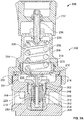
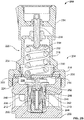
FIGS. 2A and2B illustrate anexample fluid regulator 200 described herein.FIG. 2A illustrates theexample fluid regulator 200 in aclosed position 202 andFIG. 2B illustrates theexample fluid regulator 200 in anopen position 204. - Referring to
FIGS. 2A and2B , theexample fluid regulator 200 includes a regulator body having an upper body portion orbonnet 206 coupled (e.g., threadably coupled) to a lower body portion orvalve body 208. Thevalve body 208 forms a fluid flow path between aninlet 210 and anoutlet 212 of thefluid regulator 200. Adiaphragm 214 is captured between thevalve body 208 and thebonnet 206 so that afirst side 216 of thediaphragm 214 and thebonnet 206 define aload chamber 218 to receive aload assembly 220. Asecond side 222 of thediaphragm 214 and aninner surface 224 of thevalve body 208 define asensing chamber 226. Thesensing chamber 226 is fluidly coupled to theoutlet 212 via apassage 228 and senses the pressure of the fluid at theoutlet 212. In the illustrated example, thediaphragm 214 is a metal diaphragm composed of, for example, stainless steel. - The
load assembly 220 is operatively coupled to thediaphragm 214 via a diaphragm plate or back-upplate 230 and provides a reference force or load (e.g., a pre-set force) to thediaphragm 214. In this example, theload assembly 220 includes a biasing element 232 (e.g., a spring) disposed within theload chamber 218 that provides a load to thediaphragm 214 via the back-upplate 230. Aspring adjuster 234 adjusts (e.g., increases or decreases) the amount of a preset force or load that the biasingelement 232 exerts on thefirst side 216 of thediaphragm 214. As shown, thespring adjustor 234 includes a control knob keyed to ascrew 236 that is threadably coupled to thebonnet 206 and engages anadjustable spring seat 238. Rotation of the control knob in a first direction (e.g., a clockwise direction) or a second direction (e.g., a counterclockwise direction) varies the amount of compression of the biasing element 232 (e.g., compresses or decompresses the biasing element 232) and, thus, the amount of load exerted on thefirst side 216 of thediaphragm 214. - A valve apparatus or
valve cartridge assembly 240 is disposed within abore 242 of thevalve body 208 that defines aninlet chamber 244 fluidly coupled to theinlet 210. Thevalve apparatus 240 includes apoppet 246 that moves toward avalve seat 248 to restrict fluid flow between theinlet 210 and theoutlet 212 when thefluid regulator 200 is in theclosed position 202. Thepoppet 246 moves away from thevalve seat 248 to allow fluid flow between theinlet 210 and theoutlet 212 when thefluid regulator 200 is in theopen position 204. A biasingelement 250 biases thepoppet 246 toward thevalve seat 248. A seal 252 (e.g., an O-ring) is disposed between thevalve apparatus 240 and thevalve body 208 of thefluid regulator 200 to provide a seal between thesensing chamber 226 and theinlet chamber 244. - In operation, the
example fluid regulator 200 fluidly couples to, for example, an upstream pressure source providing a relatively high pressure fluid (e.g., a gas) via theinlet 210 and fluidly couples to, for example, a low pressure downstream device or system via theoutlet 212. Thefluid regulator 200 regulates the outlet pressure of the fluid flowing through thefluid regulator 200 to a desired pressure corresponding to the preset load provided by theadjustable load assembly 220. - To achieve a desired outlet pressure, the control knob is rotated (e.g., in a clockwise or counterclockwise direction) to increase or decrease the load exerted by the biasing
element 232 on thefirst side 216 of thediaphragm 214. The load provided by the biasingelement 232 is adjusted to correspond to a desired outlet pressure. With the reference pressure set, thesensing chamber 226 senses a pressure of the pressurized fluid at theoutlet 212 via thepassage 228, which causes thediaphragm 214 to move in response to pressure changes in thesensing chamber 226. - For example, as the fluid flows between the
inlet 210 and theoutlet 212, the pressure of the fluid at theoutlet 212 increases. As the pressure of the pressurized fluid in thesensing chamber 226 increases, the pressure of the fluid exerts a force on thesecond side 222 of thediaphragm 214 to cause thediaphragm 214 and the biasingelement 232 to move in a rectilinear motion away from thevalve body 208. In turn, the biasingelement 250 of thevalve apparatus 240 causes thepoppet 246 to move toward thevalve seat 248 to restrict fluid flow between theinlet 210 and theoutlet 212. A pressure of the fluid in thesensing chamber 226 that exerts a force on thesecond side 222 of thediaphragm 214 that is greater than the reference pressure or force exerted by theload assembly 220 on thefirst side 216 of thediaphragm 214 causes the back-upplate 230 to move away from thevalve body 208 to allow thepoppet 246 to sealingly engage thevalve seat 248 to restrict or prevent fluid flow through thefluid regulator 200 as shown inFIG. 2A . - When the pressure of the pressurized fluid in the
sensing chamber 226 is less than the reference pressure or force exerted by the biasingelement 232 on thefirst side 216 of thediaphragm 214, thediaphragm 214 moves, bends or flexes toward thevalve body 208. In turn, the back-upplate 230 engages astem portion 254 of thepoppet 246 to move thepoppet 246 away from thevalve seat 248 to allow or increase fluid flow between theinlet 210 and theoutlet 212. Thepoppet 246 moves toward thevalve seat 248 to prevent or restrict fluid flow between theinlet 210 and theoutlet 212 when the pressure differential across thediaphragm 214 is substantially near zero (i.e., the pressure of the fluid in thesensing chamber 226 is regulated to a pressure that generates a force substantially equal to the load provided by the load assembly 220). - During operation as shown in
FIGS. 2A and2B , thediaphragm 214 moves flexes, or bends between a first position shown inFIG. 2A to move thepoppet 246 toward theclosed position 202 and a second position shown inFIG. 2B to move thepoppet 246 toward theopen position 204. -
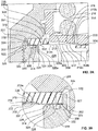
FIGS. 3A and 3B illustrate enlarged portions of thefluid regulator 200 ofFIGS. 2A and2B . As most clearly shown inFIGS. 3A and 3B , thediaphragm 214 of the illustrated example includes aperipheral edge 302, acentral portion 304, and an intermediate, movable orflexible portion 306 between theperipheral edge 302 and thecentral portion 304. Each of theperipheral edge 302 and thecentral portion 304 has a substantially planar or flat surface. Theintermediate portion 306 has a plurality of wave-shaped contours orconvolutions 308 that flex or bend when thediaphragm 214 moves between the first and second positions shown inFIGS. 2A and2B . In particular, each of thecontours 308 of theintermediate portion 306 includes a convex portion orcurved surface 310 and a concave portion orcurved surface 312 that form a continuous smooth curve or wave-shaped contour orconvolution 308. Each of theconvex portions 310 and/or theconcave portions 312 may have substantially similar radius of curvatures or may have varying radius of curvatures. For example, a firstconvex portion 310a and/orconcave portion 312a of acontour 308a may have a first radius of curvature and a secondconvex portion 310b and/orconcave portion 312b of acontour 308b may have a second radius of curvature different from the first radius of curvature. Thecontours 308 significantly increase the sensitivity of thediaphragm 214 to enable thefluid regulator 200 to have a more compact dimensional envelope. Thediaphragm 214 is composed of a metallic material such as, for example, stainless steel. - To reduce stress concentration on the
intermediate portion 306 of thediaphragm 214, thefluid regulator 200 includes one or more diaphragm interfaces or support surfaces 314, 316 and/or 318 adjacent thesensing chamber 226. Each of the diaphragm interfaces 314, 316 and/or 318 increases the cycle life or fatigue life of thediaphragm 214. In particular, each of the diaphragm interfaces 314, 316 and/or 318 substantially increases a contact surface area when engaged with thediaphragm 214, thereby reducing the stress concentrations on thediaphragm 214 during operation. In some examples, a fluid regulator only employs one of the diaphragm interfaces 314, 316 or 318. However, any combination of theinterfaces - In the illustrated example, the
diaphragm interface 314 is integrally formed with thevalve body 208 as a unitary piece or structure. As shown, thevalve body 208 has anannular wall 320 that defines thediaphragm interface 314 at an upper edge orportion 322 of theannular wall 320 adjacent theinner surface 224. Thediaphragm interface 314 of thevalve body 208 includes a ring-shaped seat ordiaphragm mount 324 to hold, receive or engage theperipheral edge 302 of thediaphragm 214. The ring-shapedseat 324 includes a curved, slanted or rampedsurface 326 that includes a rounded or radiusededge 326a adjacent thediaphragm mount 324 to support a portion of theperipheral edge 302 and/or theintermediate portion 306 of thediaphragm 214 that moves or flexes during operation of thefluid regulator 200. - The
diaphragm mount 324 has a substantially planar or flat surface to receive or engage theperipheral edge 302 of thediaphragm 214. As shown, thediaphragm mount 324 is substantially perpendicular to theinner surface 224. The rampedportion 326 and radiusededge 326a are located between thediaphragm mount 324 and theinner surface 224. The rampedportion 326 may include a curved surface having uniform radius of curvature or a plurality of curved surfaces having varying radii of curvatures that form a continuous ramped portion. The rampedportion 326 and/or thediaphragm mount 324 provide a substantially tight metal-to-metal seal when thediaphragm 214 is coupled to thefluid regulator 200. In some examples, to facilitate a metal-to-metal seal, ashoulder 325 of thediaphragm mount 324 adjacent a stepped,annular wall 327 of thevalve body 208 is offset (e.g., a 0.015 inch offset) relative to the ramped portion 326 (e.g., lower than the rampedportion 326 in the orientation ofFIG. 3A ). In this manner, when thebonnet 206 coupled to thevalve body 208, a torque applied to the rampedportion 326 of thevalve body 208 causes at least a portion of the rampedsurface 326 to deform or flatten to provide a substantially tight metal-to-metal seal. Thevalve body 208 may be composed of a relatively softer material than the material of thediaphragm 214. - In operation, the ramped
portion 326 enables a portion of thediaphragm 214 adjacent theperipheral edge 302 to flex or roll along the rampedportion 326. For example, when theintermediate portion 306 of thediaphragm 214 adjacent theperipheral edge 302 moves or flexes toward thevalve body 208 to the second position (e.g., the position ofFIG. 2B ), thesecond side 222 of theintermediate portion 306 adjacent theperipheral edge 302 engages the rampedportion 326 of thevalve body 208. The rampedportion 326 increases the contact surface area between theintermediate portion 306 and thevalve body 208 to more evenly distribute or reduce stresses imparted to theintermediate portion 306 across the area or portion of thediaphragm 214 that engages or rolls about the rampedportion 326. In other words, the ramped orcurved surface 326 enables theintermediate portion 306 adjacent theperipheral edge 302 to flex or bend while subjected to significantly reduced stress concentration. - For example, in contrast to the known
fluid regulator 100 ofFIGS. 1A and1B , thediaphragm interface 314 or rampedportion 326 of thevalve body 208 significantly reduces or eliminates a pinch point or area (e.g., thepinch point 140 ofFIG. 1A and1B ) between thevalve body 208 and thebonnet 206. The rampedportion 326 enables a larger portion or area of thediaphragm 214 adjacent theperipheral edge 302 to roll or flex about the rampedportion 326 with less rigidity or stiffness compared to thepinch point 140 ofFIG. 1B , thereby reducing concentration of stresses by distributing the stresses over a larger contact surface area of thediaphragm 214 adjacent theperipheral edge 302. In other words, thediaphragm 214 bends about the rampedportion 326 with less compressive stress imparted to thesecond side 222 of thediaphragm 214 and less tensile stress imparted to thefirst side 216 of thediaphragm 214 compared to the compressive and tensile stresses imparted to thediaphragm 112 of thefluid regulator 100 ofFIGS. 1A and1B when thediaphragm 112 bends about thepinch point 140. Thus, the rampedportion 326 increases a contact surface area between thevalve body 208 and theintermediate portion 306, thereby reducing stress concentration across theintermediate portion 306 of thediaphragm 214 adjacent theperipheral edge 302. The rampedportion 326 may be formed via machining, casting or any other suitable manufacturing process(es). As shown, to provide a redundant seal and/or to facilitate assembly when a substantially tight metal-to-metal seal is not required, thediaphragm interface 314 ordiaphragm mount 324 may optionally include arecess 328 to receive an O-ring 330 to provide a seal (e.g., a redundant seal) between thevalve body 208 and thebonnet 206. The O-ring 330 may facilitate assembly because it requires less torque to provide a seal compared to a torque required to provide a metal-to-metal seal. - In the illustrated example, the
fluid regulator 200 employs a ring-shaped clamp orretainer 332 to hold or clamp thediaphragm 214 between thebonnet 206 and thevalve body 208. Also, theretainer 332 defines thediaphragm interface 316 that provides support to theintermediate portion 306 adjacent theperipheral edge 302. Thediaphragm interface 316 includes adiaphragm clamping portion 334 and adiaphragm support portion 336 adjacent thediaphragm clamping portion 334. - As shown, the
peripheral edge 302 of thediaphragm 214 is clamped between thediaphragm clamping portion 334 and thediaphragm mount 324 of thevalve body 208. In particular, thediaphragm clamping portion 334 of theretainer 332 transfers a load to theperipheral edge 302 of thediaphragm 214 when thevalve body 208 is coupled to thebonnet 206 to help provide a metal-to-metal seal between thediaphragm 214 and thevalve body 208 when a torque is applied to thebonnet 206 during assembly of thebonnet 206 and thevalve body 208. When coupled to thevalve body 208, thebonnet 206 provides a compressive load to theperipheral edge 302 of thediaphragm 214 via theretainer 332. In this example, theretainer 332 is composed of, for example, a metallic material such as stainless steel to provide a metal-to-metal contact between theretainer 332, thevalve body 208, thebonnet 206 and thediaphragm 214. - The
diaphragm support portion 336 of thediaphragm interface 316 includes a curved orarcuate surface 336a that protrudes away from thediaphragm clamping portion 334 and inwardly from theperipheral edge 302 toward thesensing chamber 226. For example, thediaphragm support portion 336 extends beyond or past theinner surface 224 orupper edge 322 of theannular wall 320 of thevalve body 208. Such an extension enables thediaphragm support portion 336 to engage thefirst side 216 of theintermediate portion 306 adjacent theperipheral edge 302 to support thediaphragm 214. In particular, thediaphragm support portion 336 engages at least aportion 337 of theconcave portion 310 of thecontour 308 of thefirst side 216 of thediaphragm 214. Thus, theretainer 332 or thediaphragm interface 316 and the rampedportion 326 ordiaphragm interface 314 engage opposing faces orsides diaphragm 214. Further, as shown, inFIGS. 3A and 3B , thecurved surface 336a has a shape or profile substantially similar to the shape or profile of theintermediate portion 306 adjacent theperipheral edge 302 such that the curved surface matably engages theintermediate portion 306 adjacent theperipheral edge 302. -
FIG. 4 depicts a cross-section of theretainer 332 ofFIGS. 3A and 3B . Referring also toFIG. 4 , theretainer 332 is a ring-shapedclamp 402 having anouter diameter 404 and aninner diameter 406. For example, theouter diameter 404 may be approximately 64.5 millimeters and theinner diameter 406 is approximately 44.5 millimeters. In this example, thediaphragm clamping portion 334 has alength 408 and thediaphragm support portion 336 has alength 410. For example, thelength 408 is approximately 5.25 millimeters and thelength 410 is approximately 4.75 millimeters. However, other lengths and/or diameters may be used to suit the needs of a particular application. - Also, in the illustrated example, the curved surface of the
diaphragm support portion 336 has a radius ofcurvature 412 that is substantially similar to a radius of curvature of theintermediate portion 306 adjacent theperipheral edge 302. Thus, thecurved surface 336a may have a curved profile that is complementary to a curved profile of theintermediate portion 306 adjacent theperipheral edge 302. For example, theradius 412 of the curved surface is approximately 8.5 millimeters. However, the radius of curvature may be varied as needed to suit the needs of a particular application. - In this manner, the
curved surface 336a engages theintermediate portion 306 adjacent theperipheral edge 302 with a relatively greater contact surface area compared to, for example, thefluid regulator 100 ofFIG. 1A and1B , thereby reducing stress concentration at theintermediate portion 306 adjacent theperipheral edge 302 when thediaphragm 214 moves between the first and second positions during operation. For example, theretainer 332 significantly reduces high compressive stress concentrations on thefirst side 216 of thediaphragm 214 and high tensile stress concentrations on thesecond side 222 of thediaphragm 214 when a pressure or force is applied to thesecond side 222 of thediaphragm 214 via thesensing chamber 226 compared to the compressive and tensile stresses imparted to thediaphragm 112 of thefluid regulator 100 ofFIGS. 1A and1B when thediaphragm 112 bends about thepinch point 140. As a result, thediaphragm interface 316 significantly improves the cycle life or fatigue life of thediaphragm 214. In other examples, thecurved surface 336a may have a radius of curvature that is different than the radius of curvature of theintermediate portion 306 of thediaphragm 214. - Although not shown, the
retainer 332 and/or thediaphragm interface 316 or thediaphragm support portion 336 may be integrally formed with thebonnet 206 as a unitary piece or structure. In other words, thediaphragm support portion 336 may extend from aninner surface 338 of thebonnet 206 and theretainer 332 may be eliminated. -
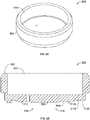
FIGS. 5A and 5B illustrate the back-upplate 230 of thefluid regulator 200. Referring toFIGS. 2A ,2B ,3A ,5A and 5B , the back-upplate 230 includes the diaphragm interface orsupport surface 318 to engage and support thediaphragm 214. The back-upplate 230 has acylindrical body portion 502 having acavity 504 to receive thebiasing element 232 of theload assembly 220. As shown, thediaphragm interface 318 includes a curved support surface or face 506 to increase a contact surface area between thediaphragm 214 and the back-upplate 230. In the illustrated example, thediaphragm interface 318 of the back-upplate 230 includes a substantially planar or flatengaging surface 508 to engage the central portion 304 (FIG. 3A ) of thediaphragm 214. - The curved support surface or
face 506 has a curved profile that is complementary to a profile of the portion of thediaphragm 214 that engages the back-upplate 320. In this manner, thecurved support surface 506 provides a relatively greater contact surface area to engage theintermediate portion 306 or thecontours 308 of thediaphragm 214. In the illustrated example, thecurved support surface 506 includes a concavecurved portion 510 adjacent a convexcurved portion 512 to provide a smooth continuous wave-shaped curved support surface. In other words, the cross-sectional shape of thecurved support portion 506 is substantially similar to the cross-sectional shape of thecontours 308 of thediaphragm 214. For example, the concavecurved portion 510 of thecurved support surface 506 has a radius of curvature that is substantially similar to the radius of curvature of theconvex portion 310 of thecontours 308 of thediaphragm 214. Likewise, the convexcurved portion 512 of thecurved support surface 506 has a radius of curvature that is substantially similar to the radius of curvature of theconcave portion 312 of thecontours 308 of thediaphragm 214. - Also, a first concave curved portion 510a of the
curved support surface 506 may have a radius of curvature that is different than, or similar to, a radius of curvature of a second concavecurved portion 510b of thecurved support surface 506. For example, the radius of curvature of the concavecurved portions 510 may range between 6.0 and 8.0 millimeters. Similarly, a first convexcurved portion 512a of thecurved support surface 506 may have a radius of curvature that is different than, or similar to, a radius of curvature of a second convexcurved portion 512b. For example, the radius of curvature of the convexcurved portions 512 may range between 8.0 and 10.0 millimeters. - Thus, in contrast to the back-up
plate 122 ofFIG. 1A , thediaphragm interface 318 of the back-upplate 230 substantially matably engages theintermediate portion 306 of thediaphragm 214 to provide an increased contact surface area between the back-upplate 230 and thediaphragm 214 that affect (e.g., reduces) an amount of stress imparted to theintermediate portion 306 of thediaphragm 214 that moves in response to pressure changes in thesensing chamber 226. In this example, thediaphragm support surface 506 reduces localized stress concentrations on thediaphragm 214. For example, when thediaphragm 214 moves between the position shown inFIG. 2A and the position shown inFIG. 2B , the back-upplate 230 engages (e.g., matably engages) theintermediate portion 306 of thediaphragm 214 with a relatively great contact surface area. As a result, a reduction in localized stress concentrations significantly improves or increases the cycle life or fatigue life of thediaphragm 214. - In other examples, the
diaphragm interface 318 of the back-upplate 230 includes a shape, profile or cross-section that is different than a shape, profile or cross-section of thediaphragm 214. For example, a radius of curvature between thecurved support surface 506 and thecontours 308 of thediaphragm 214 may be different such that thediaphragm 214 does not matably engage the back-upplate 230, but still provides an increased contact surface area relative to the back-up plate ofFIGS. 1A and1B . - Thus, the
fluid regulator 200 described herein includes the diaphragm interfaces 314, 316 and/or 318, which may be configured to have a shape or profile that is substantially similar to the shape or profile of thediaphragm 214 to increase a contact surface area between the diaphragm interfaces 314, 316 and/or 318 and thediaphragm 214. For example, each of the diaphragm interfaces 314, 316 and/or 318 may include a respective curved surface or portion to increase a contact surface area when engaged by thediaphragm 214 to reduce stress concentration imparted to a portion of thediaphragm 214 that moves during operation. In some examples, a support surface of the diaphragm interfaces 314, 316 and/or 318 has a cross-sectional shape or profile that is substantially similar to the cross-sectional shape or profile of thediaphragm 214 such that the diaphragm interfaces 314, 316 and/or 318 matably engage at least a portion of thediaphragm 214. As a result, the diaphragm interfaces 314, 316 and/or 318 reduce stress concentrations imparted to thediaphragm 214, thereby increasing the cycle life or fatigue life of thediaphragm 214. For example, the cycle life of thediaphragm 214 is approximately 85,000 cycles while the life cycle of thediaphragm 112 ofFIGS. 1A and1B is approximately 10,000 cycles. In some examples, thefluid regulator 200 may be implemented with only one of the diaphragm interfaces 314, 316 and/or 318 or any combination of theinterfaces
Claims (12)
- A fluid regulator (200) comprising:a fluid flow passageway between an inlet (210) and an outlet (212);a sensing chamber (226) defining a portion of the fluid flow passageway;a diaphragm (214) arranged to sense a pressure in the sensing chamber; anda plurality of diaphragm interfaces (316, 318) adjacent the sensing chamber, each of the diaphragm interfaces having a curved surface (326a, 336a, 506) to contact a portion of the diaphragm that moves in response to pressure changes in the sensing chamber, each of the curved surfaces to affect an amount of stress imparted to the portion of the diaphragm during operation of the fluid regulator;characterized in thatthe plurality of diaphragm interfaces (316, 318) comprises a first diaphragm interface (318) comprising a back-up plate (230) arranged in a loading chamber (218) opposite the sensing chamber, the back-up plate including a first curved surface (506) to contact the portion of the diaphragm during operation of the fluid regulator; andin that the plurality of diaphragm interfaces (316, 318) further comprises a second diaphragm interface (316) comprising a ring-shaped clamp (332) arranged around the back-up plate, the ring-shaped clamp including a clamping portion (334) and a support portion (336), the clamping portion being configured to hold a peripheral edge (302) of the diaphragm, and the support portion being configured to project inwardly from the peripheral edge of the diaphragm and comprising a second curved surface (336a) to contact only one side of the portion of the diaphragm during operation of the fluid regulator.
- The fluid regulator of claim 1, wherein the plurality of diaphragm interfaces further comprises a third diaphragm interface, wherein the third diaphragm interface comprises a ring-shaped seat (324) to hold the peripheral edge (302) of the diaphragm, and wherein the ring-shaped seat comprises a third curved surface (326) comprising a radiused inner edge (326a) to contact the portion of the diaphragm during operation of the fluid regulator.
- The fluid regulator of claim 2, wherein the second curved surface of the support portion of the ring-shaped clamp and the radiused inner edge of the third curved surface of the ring-shaped seat contact opposing faces of the portion of the diaphragm during operation of the fluid regulator.
- The fluid regulator of any of the preceding claims, wherein the second curved surface of the support portion of the ring-shaped clamp has a curved profile that is complementary to a curved profile of the portion of the diaphragm.
- The fluid regulator of any of the preceding claims, wherein the first curved surface comprises a face of the back-up plate having a curved profile complementary to a profile of the portion of the diaphragm.
- The fluid regulator of any of the preceding claims, wherein the curved surfaces increase a contact surface area between the diaphragm interfaces and the portion of the diaphragm.
- The fluid regulator of any of claim 1, wherein the back-up plate comprises a support surface to engage the diaphragm.
- The fluid regulator of claim 7, wherein the support surface of the back-up-plate includes a central portion having a substantially planar support surface (508) and an outer portion (506) adjacent the central portion, the outer portion having a wave-shaped contour and forming the first curved surface.
- The fluid regulator of claim 8, wherein the central portion of the back-up plate is configured to engage a central portion of the diaphragm, and the first curved surface (506) of the back-up plate is configured to engage a substantially complementary wave-shaped contour of an intermediate portion (306) of the diaphragm adjacent the central portion.
- The fluid regulator of claim 9, wherein the wave-shaped contour of the first curved surface of the back-up plate includes a radius of curvature that is substantially similar to a radius of curvature of the wave-shaped contour of the intermediate portion of the diaphragm.
- The fluid regulator of claim 1, comprising a biasing element configured to provide a biasing load to the diaphragm via the back-up plate.
- The fluid regulator of claim 1, further comprising a valve apparatus (240) disposed within an inlet chamber (244) of the fluid flow passageway fluidly coupled to the inlet (210), the valve apparatus including a valve seat (248), a poppet (246) that is movable relative to the valve seat to control fluid flow through the fluid flow passageway, and a biasing element (250) arranged to bias the poppet toward the valve seat.
Applications Claiming Priority (2)
| Application Number | Priority Date | Filing Date | Title |
|---|---|---|---|
| US13/052,475 US9874883B2 (en) | 2009-07-02 | 2011-03-21 | Diaphragm interface apparatus to improve a cycle life of a diaphragm |
| PCT/US2012/026099 WO2012148532A1 (en) | 2011-03-21 | 2012-02-22 | Diaphragm interface apparatus to improve a cycle life of a diaphragm |
Publications (2)
| Publication Number | Publication Date |
|---|---|
| EP2689310A1 EP2689310A1 (en) | 2014-01-29 |
| EP2689310B1 true EP2689310B1 (en) | 2019-07-31 |
Family
ID=45888470
Family Applications (1)
| Application Number | Title | Priority Date | Filing Date |
|---|---|---|---|
| EP12710818.1A Active EP2689310B1 (en) | 2011-03-21 | 2012-02-22 | Diaphragm interface apparatus to improve a cycle life of a diaphragm |
Country Status (12)
| Country | Link |
|---|---|
| US (1) | US9874883B2 (en) |
| EP (1) | EP2689310B1 (en) |
| JP (2) | JP2014509034A (en) |
| KR (1) | KR20140020283A (en) |
| CN (1) | CN202418758U (en) |
| AU (1) | AU2012249193B2 (en) |
| BR (1) | BR112013024097A2 (en) |
| CA (1) | CA2830198C (en) |
| MX (1) | MX354784B (en) |
| NO (1) | NO20131311A1 (en) |
| RU (1) | RU2627022C2 (en) |
| WO (1) | WO2012148532A1 (en) |
Families Citing this family (9)
| Publication number | Priority date | Publication date | Assignee | Title |
|---|---|---|---|---|
| US20110174398A1 (en) * | 2009-07-02 | 2011-07-21 | Jason David Clifford | Valve apparatus to prevent contamination of fluid in a fluid regulator |
| US9371925B2 (en) | 2013-07-30 | 2016-06-21 | Tescom Corporation | Fluid regulators having corrugated diaphragms |
| US9441745B2 (en) | 2014-03-03 | 2016-09-13 | Emerson Process Management Regulator Technologies, Inc. | Apparatus to interface with a corrugated diaphragm |
| CN104006178B (en) * | 2014-06-09 | 2016-09-07 | 宁波新佳行自动化工业有限公司 | Metal pressure regulator valve |
| CN106838397B (en) * | 2015-10-20 | 2020-12-08 | 艾默生过程管理调节技术公司 | Pressure regulating device with variable travel stop |
| ES2733448T3 (en) * | 2016-01-04 | 2019-11-29 | Danfoss As | Capsule for a valve and valve |
| CN121957178A (en) * | 2020-08-07 | 2026-05-01 | 固瑞克明尼苏达有限公司 | Back pressure regulator |
| US11885419B1 (en) * | 2022-07-08 | 2024-01-30 | Ultra Flow Holdings, LLC | Pressure regulating valve |
| LU504900B1 (en) | 2023-08-11 | 2025-02-11 | Rotarex S A | Pressure reducer with seat and shutter inserted from a bottom face |
Family Cites Families (88)
| Publication number | Priority date | Publication date | Assignee | Title |
|---|---|---|---|---|
| US330263A (en) | 1885-11-10 | Gas-regulator | ||
| US466275A (en) * | 1891-12-29 | fasoldt | ||
| US1045791A (en) | 1912-08-01 | 1912-11-26 | Stuart W Cramer | Flexible metallic diaphragm. |
| US1286397A (en) | 1917-12-26 | 1918-12-03 | Frederich Marggraff | Expansion-valve for refrigerating apparatus. |
| US1452252A (en) | 1922-05-12 | 1923-04-17 | Muller Joseph | Automatic safety expansion valve |
| US1543264A (en) | 1923-09-21 | 1925-06-23 | Porter A Morgan | Vacuum-controlled regulator |
| GB335044A (en) | 1928-10-27 | 1930-09-18 | Alfred Curt Becker | Improvements relating to gas pressure regulators |
| US1891547A (en) * | 1930-07-02 | 1932-12-20 | William F Krichbaum | Auxiliary operated governing valve |
| GB451379A (en) | 1935-05-28 | 1936-08-05 | Henry Noel Negretti | Improvements in or relating to diaphragms for pressure gauges and the like |
| US2082227A (en) * | 1935-12-14 | 1937-06-01 | Victor Welding Equipment Co | Gas pressure regulator |
| GB521273A (en) | 1938-11-10 | 1940-05-16 | Smith & Sons Ltd S | Improvements in or relating to pressure-sensitive capsules |
| US2348388A (en) * | 1940-12-06 | 1944-05-09 | Alexander F Jenkins | Fluid pressure regulator |
| US2667127A (en) | 1946-07-20 | 1954-01-26 | Sulzer Ag | Motor-driven pump |
| US2612728A (en) | 1946-10-02 | 1952-10-07 | Union Carbide & Carbon Corp | Fluid pressure regulator |
| US2521637A (en) | 1948-03-17 | 1950-09-05 | Lack Sydney Walter | Reducing valve mechanism |
| US2664674A (en) * | 1948-04-27 | 1954-01-05 | Rockwell Mfg Co | Fluid regulator valve |
| US2707966A (en) * | 1950-05-25 | 1955-05-10 | John F Taplin | Pressure regulator valve |
| US2806481A (en) * | 1953-04-08 | 1957-09-17 | Norgren Co C A | Pilot controlled pressure regulator |
| US2918081A (en) * | 1954-02-09 | 1959-12-22 | Air Prod Inc | Fluid pressure control device |
| US2894526A (en) * | 1954-07-26 | 1959-07-14 | United Aircraft Prod | Pressure regulating valve |
| GB834574A (en) | 1956-07-06 | 1960-05-11 | Int Basic Economy Corp | Valve |
| US2942624A (en) | 1956-11-14 | 1960-06-28 | Penn Controls | Pressure responsive actuator |
| US3120377A (en) * | 1960-01-07 | 1964-02-04 | Emulsol Egg Products Corp | Apparatus for producing dressing |
| US3113756A (en) * | 1961-05-08 | 1963-12-10 | Lincoln Tool And Machine Co In | Regulator |
| US3434395A (en) | 1964-10-26 | 1969-03-25 | Holley Carburetor Co | Pressure responsive mechanism |
| JPS457009Y1 (en) * | 1964-11-21 | 1970-04-06 | ||
| US3387622A (en) * | 1965-09-22 | 1968-06-11 | Flair Mfg Corp | Valve |
| GB1210065A (en) * | 1967-03-31 | 1970-10-28 | I V Pressure Controllers Ltd | Improvements in or relating to diaphragms |
| DE1808567B2 (en) | 1968-11-13 | 1972-03-23 | Max Planck Gesellschaft zur Forderung der Wissenschaften e V , 3400 Got tingen | VACUUM CONTROL VALVE AND OPERATING PROCEDURE FOR IT |
| US3586037A (en) * | 1969-05-26 | 1971-06-22 | Victor Equipment Co | Single stage, compensated pressure regulator |
| JPS5114730B1 (en) * | 1970-07-25 | 1976-05-12 | ||
| US3667722A (en) * | 1970-10-22 | 1972-06-06 | Ite Imperial Corp | Proportional valve |
| US3819286A (en) | 1971-11-01 | 1974-06-25 | Saip Spa | Hydraulic tightening-up device for very high stresses |
| US4055198A (en) * | 1974-08-15 | 1977-10-25 | Tannetics, Inc. | Excess pressure relieving valve |
| US4196744A (en) | 1976-09-21 | 1980-04-08 | Eaton Corporation | Exhaust gas recirculation control |
| JPS628470Y2 (en) * | 1979-06-26 | 1987-02-27 | ||
| US4457329A (en) * | 1981-12-04 | 1984-07-03 | Air Products And Chemicals, Inc. | Safety pressure regulator |
| ES8401214A1 (en) | 1982-01-27 | 1983-12-16 | Eltek Srl | Thermoelectric valves |
| US4471802A (en) * | 1983-04-12 | 1984-09-18 | Victor Equipment Company, Inc. | Pressure regulator assembly with improved cartridge |
| US4543832A (en) | 1983-09-30 | 1985-10-01 | Transducers, Inc. | Overload protected pressure transducer |
| US4624442A (en) | 1985-01-23 | 1986-11-25 | Duffy John W | Control regulator having a rolling diaphragm |
| JPH0426889Y2 (en) * | 1985-04-02 | 1992-06-29 | ||
| US4741252A (en) | 1986-09-24 | 1988-05-03 | Allied-Signal Inc. | Diaphragm of the rolling type having a membrane portion and a reinforcing portion |
| GB8819741D0 (en) | 1988-08-19 | 1988-09-21 | Hattersley Heaton Ltd | Seat for butterfly valve |
| US5292024A (en) * | 1992-05-19 | 1994-03-08 | Rehrig Pacific Company, Inc. | Plastic pail assembly for hazardous materials |
| US5449003A (en) * | 1992-12-28 | 1995-09-12 | Sugimura; Kazuo | Undulated container for undulated diaphragm and diaphragm device |
| US5443083A (en) * | 1993-02-11 | 1995-08-22 | Itt Corporation | Pressure-reducing regulator for compressed natural gas |
| US5335584A (en) | 1993-03-30 | 1994-08-09 | Baird Dayne E | Improved diaphragm |
| CA2125206C (en) | 1993-06-07 | 2000-07-25 | Yasuo Yamabe | Vacuum valve control device and vacuum valve |
| US5762314A (en) * | 1993-06-08 | 1998-06-09 | O.I. Corporation | Diaphragm valve for cryogenic applications |
| DE4430472A1 (en) | 1994-08-27 | 1996-02-29 | Bosch Gmbh Robert | Pressure control valve |
| CA2131108C (en) * | 1994-08-30 | 2005-06-07 | Stephen A. Carter | Two-stage pressure regulator |
| US5567130A (en) * | 1994-11-09 | 1996-10-22 | Graco Inc. | Reinforced cover configuration for a diaphragm pump |
| JP3291151B2 (en) | 1995-02-15 | 2002-06-10 | 株式会社フジキン | Diaphragm valve |
| JP2791546B2 (en) * | 1995-02-27 | 1998-08-27 | 株式会社ヨシタケ | Control valve with metal diaphragm |
| US5725007A (en) | 1995-07-07 | 1998-03-10 | Stubbs; William L. | Valve mechanism and method for making same |
| US5586569A (en) * | 1995-07-27 | 1996-12-24 | Parker-Hannifin Corporation | Pneumatic pressure regulator |
| JP4156672B2 (en) * | 1996-07-16 | 2008-09-24 | コントロールズ コーポレイション オブ アメリカ | Gas flow control equipment for high purity and highly corrosive gas facilities |
| US5829477A (en) | 1996-09-04 | 1998-11-03 | Taprite-Fassco Manufacturing, Inc. | Modular regulator |
| DE19650194C1 (en) * | 1996-12-04 | 1998-04-02 | Daimler Benz Ag | Fuel tank filling level limit device |
| JP3833323B2 (en) * | 1997-01-07 | 2006-10-11 | Smc株式会社 | Pressure reducing valve |
| JP3796006B2 (en) * | 1997-05-27 | 2006-07-12 | Smc株式会社 | Valve seal mechanism |
| US5904178A (en) * | 1997-06-20 | 1999-05-18 | Controls Corporation Of America | Gas filter for regulator valve, and improved regulator valve employing the filter |
| US5881997A (en) * | 1997-11-24 | 1999-03-16 | Fujikin Incorporated | Metal diaphragm type valve |
| US5950652A (en) * | 1998-02-11 | 1999-09-14 | Parker Hannifin Corporation | Load balanced pressure regulator and method and apparatus for delivering process gas for manufacturing semiconductor devices employing same |
| US6536466B1 (en) * | 1998-09-04 | 2003-03-25 | Wanner Engineering | Pressure regulator apparatus |
| US6394417B1 (en) * | 1998-10-09 | 2002-05-28 | Swagelok Co. | Sanitary diaphragm valve |
| US6276907B1 (en) | 1999-08-12 | 2001-08-21 | Wagner Spray Tech Corporation | Hydraulically driven diaphragm pump |
| EP1690031A2 (en) | 2003-11-25 | 2006-08-16 | Garlock Sealing Technologies LLC | Corrugated gasket core with profiled surface cross reference to related applications |
| DE202004006191U1 (en) | 2004-04-20 | 2004-08-19 | Radtke, Reinhard | Precision valve for control of liquids in e.g. surface treatment systems uses ribbed, resilient membrane as piston guide and acts as partition between high and low pressure zones, without control hysteresis |
| JP4813047B2 (en) * | 2004-11-29 | 2011-11-09 | シーケーディ株式会社 | Diaphragm valve |
| FR2878985B1 (en) | 2004-12-07 | 2007-04-20 | R G S A S Di Rosaria Galli & C | BALANCED PRESSURE REDUCER |
| KR100598111B1 (en) * | 2004-12-20 | 2006-07-07 | 삼성전자주식회사 | Regulator and how to use it to supply gas |
| JP2006260385A (en) * | 2005-03-18 | 2006-09-28 | Osaka Gas Co Ltd | Pressure governor and processing method |
| US7926785B2 (en) | 2005-06-22 | 2011-04-19 | Wincek Christopher P | Valve diaphragm with a compression restraining ring, and valve including same |
| DE102006007363A1 (en) * | 2006-02-17 | 2007-08-23 | Robert Bosch Gmbh | Pilot operated pressure relief valve |
| US20090065073A1 (en) | 2007-09-11 | 2009-03-12 | Davis David B | Metal sealing disk having an elastomeric backing for use with fluid regulators |
| US20090071548A1 (en) * | 2007-09-14 | 2009-03-19 | Daryll Duane Patterson | Modular in-line fluid regulators |
| US8522809B2 (en) * | 2008-06-05 | 2013-09-03 | Illinois Tool Works Inc. | Gas regulator with venting bonnet |
| GB2464283B (en) | 2008-10-08 | 2012-09-19 | Bifold Fluidpower Ltd | Fluid flow control system and method |
| JP5366649B2 (en) * | 2009-05-15 | 2013-12-11 | トーステ株式会社 | Resin diaphragm type fluid control valve |
| US20110174398A1 (en) * | 2009-07-02 | 2011-07-21 | Jason David Clifford | Valve apparatus to prevent contamination of fluid in a fluid regulator |
| US8459297B2 (en) | 2009-07-02 | 2013-06-11 | Tescom Corporation | Balanced valve cartridge |
| US8408418B2 (en) * | 2010-11-05 | 2013-04-02 | Michael D. Stolzman | Drum cover with center support |
| US20120241033A1 (en) * | 2011-03-21 | 2012-09-27 | Jason David Clifford | Bonnet apparatus for use with fluid regulators |
| US20140034155A1 (en) | 2012-07-31 | 2014-02-06 | Fairchild Industrial Products Company | Valve Seat For A Pressure Regulator |
| US9371925B2 (en) | 2013-07-30 | 2016-06-21 | Tescom Corporation | Fluid regulators having corrugated diaphragms |
| US9441745B2 (en) | 2014-03-03 | 2016-09-13 | Emerson Process Management Regulator Technologies, Inc. | Apparatus to interface with a corrugated diaphragm |
-
2011
- 2011-03-21 US US13/052,475 patent/US9874883B2/en active Active
- 2011-09-20 CN CN2011203616661U patent/CN202418758U/en not_active Expired - Lifetime
-
2012
- 2012-02-22 BR BR112013024097A patent/BR112013024097A2/en not_active IP Right Cessation
- 2012-02-22 JP JP2014501078A patent/JP2014509034A/en active Pending
- 2012-02-22 EP EP12710818.1A patent/EP2689310B1/en active Active
- 2012-02-22 KR KR1020137026917A patent/KR20140020283A/en not_active Withdrawn
- 2012-02-22 CA CA2830198A patent/CA2830198C/en active Active
- 2012-02-22 WO PCT/US2012/026099 patent/WO2012148532A1/en not_active Ceased
- 2012-02-22 RU RU2013144282A patent/RU2627022C2/en active
- 2012-02-22 AU AU2012249193A patent/AU2012249193B2/en not_active Ceased
- 2012-02-22 MX MX2013010829A patent/MX354784B/en active IP Right Grant
-
2013
- 2013-10-01 NO NO20131311A patent/NO20131311A1/en not_active Application Discontinuation
-
2017
- 2017-07-19 JP JP2017139875A patent/JP6526751B2/en active Active
Non-Patent Citations (1)
| Title |
|---|
| None * |
Also Published As
| Publication number | Publication date |
|---|---|
| CN102691815A (en) | 2012-09-26 |
| NO20131311A1 (en) | 2013-10-01 |
| JP2017201329A (en) | 2017-11-09 |
| US9874883B2 (en) | 2018-01-23 |
| MX354784B (en) | 2018-03-21 |
| EP2689310A1 (en) | 2014-01-29 |
| RU2013144282A (en) | 2015-04-27 |
| CN202418758U (en) | 2012-09-05 |
| MX2013010829A (en) | 2013-11-01 |
| AU2012249193A1 (en) | 2013-10-03 |
| KR20140020283A (en) | 2014-02-18 |
| WO2012148532A1 (en) | 2012-11-01 |
| RU2627022C2 (en) | 2017-08-02 |
| BR112013024097A2 (en) | 2016-12-06 |
| AU2012249193B2 (en) | 2016-11-10 |
| CA2830198A1 (en) | 2012-11-01 |
| JP2014509034A (en) | 2014-04-10 |
| JP6526751B2 (en) | 2019-06-05 |
| US20110174395A1 (en) | 2011-07-21 |
| CA2830198C (en) | 2019-08-13 |
Similar Documents
| Publication | Publication Date | Title |
|---|---|---|
| AU2012249193B2 (en) | Diaphragm interface apparatus to improve a cycle life of a diaphragm | |
| US9920847B2 (en) | Apparatus to interface with a corrugated diaphragm | |
| CA2917971C (en) | Fluid regulators having corrugated diaphragms | |
| KR100963613B1 (en) | Fluid control valve | |
| US8708309B2 (en) | Self-aligning spring seat for fluid regulator and fluid regulator comprising self-aligning spring seat | |
| KR20090080474A (en) | Rectifier valve | |
| KR101020711B1 (en) | Rectifier valve | |
| JP2010164130A (en) | Back pressure control valve | |
| EP1321841A1 (en) | Constant flow valve and constant flow mixing method | |
| KR20210025655A (en) | Valve device, fluid control device, fluid control method, semiconductor manufacturing device and semiconductor manufacturing method | |
| US20120241033A1 (en) | Bonnet apparatus for use with fluid regulators | |
| EP3304237B1 (en) | Apparatus to interface with a corrugated diaphragm | |
| JP7207761B2 (en) | Valve devices and fluid control devices | |
| EP3028106B1 (en) | Fluid regulators having corrugated diaphragms | |
| US9684315B2 (en) | Control valve |
Legal Events
| Date | Code | Title | Description |
|---|---|---|---|
| PUAI | Public reference made under article 153(3) epc to a published international application that has entered the european phase |
Free format text: ORIGINAL CODE: 0009012 |
|
| 17P | Request for examination filed |
Effective date: 20131018 |
|
| AK | Designated contracting states |
Kind code of ref document: A1 Designated state(s): AL AT BE BG CH CY CZ DE DK EE ES FI FR GB GR HR HU IE IS IT LI LT LU LV MC MK MT NL NO PL PT RO RS SE SI SK SM TR |
|
| DAX | Request for extension of the european patent (deleted) | ||
| 17Q | First examination report despatched |
Effective date: 20150925 |
|
| STAA | Information on the status of an ep patent application or granted ep patent |
Free format text: STATUS: EXAMINATION IS IN PROGRESS |
|
| GRAP | Despatch of communication of intention to grant a patent |
Free format text: ORIGINAL CODE: EPIDOSNIGR1 |
|
| STAA | Information on the status of an ep patent application or granted ep patent |
Free format text: STATUS: GRANT OF PATENT IS INTENDED |
|
| INTG | Intention to grant announced |
Effective date: 20190212 |
|
| GRAS | Grant fee paid |
Free format text: ORIGINAL CODE: EPIDOSNIGR3 |
|
| GRAA | (expected) grant |
Free format text: ORIGINAL CODE: 0009210 |
|
| STAA | Information on the status of an ep patent application or granted ep patent |
Free format text: STATUS: THE PATENT HAS BEEN GRANTED |
|
| AK | Designated contracting states |
Kind code of ref document: B1 Designated state(s): AL AT BE BG CH CY CZ DE DK EE ES FI FR GB GR HR HU IE IS IT LI LT LU LV MC MK MT NL NO PL PT RO RS SE SI SK SM TR |
|
| REG | Reference to a national code |
Ref country code: CH Ref legal event code: EP Ref country code: GB Ref legal event code: FG4D |
|
| REG | Reference to a national code |
Ref country code: AT Ref legal event code: REF Ref document number: 1161583 Country of ref document: AT Kind code of ref document: T Effective date: 20190815 |
|
| REG | Reference to a national code |
Ref country code: IE Ref legal event code: FG4D |
|
| REG | Reference to a national code |
Ref country code: DE Ref legal event code: R096 Ref document number: 602012062430 Country of ref document: DE |
|
| REG | Reference to a national code |
Ref country code: NL Ref legal event code: MP Effective date: 20190731 |
|
| REG | Reference to a national code |
Ref country code: LT Ref legal event code: MG4D |
|
| REG | Reference to a national code |
Ref country code: AT Ref legal event code: MK05 Ref document number: 1161583 Country of ref document: AT Kind code of ref document: T Effective date: 20190731 |
|
| PG25 | Lapsed in a contracting state [announced via postgrant information from national office to epo] |
Ref country code: SE Free format text: LAPSE BECAUSE OF FAILURE TO SUBMIT A TRANSLATION OF THE DESCRIPTION OR TO PAY THE FEE WITHIN THE PRESCRIBED TIME-LIMIT Effective date: 20190731 Ref country code: BG Free format text: LAPSE BECAUSE OF FAILURE TO SUBMIT A TRANSLATION OF THE DESCRIPTION OR TO PAY THE FEE WITHIN THE PRESCRIBED TIME-LIMIT Effective date: 20191031 Ref country code: NL Free format text: LAPSE BECAUSE OF FAILURE TO SUBMIT A TRANSLATION OF THE DESCRIPTION OR TO PAY THE FEE WITHIN THE PRESCRIBED TIME-LIMIT Effective date: 20190731 Ref country code: HR Free format text: LAPSE BECAUSE OF FAILURE TO SUBMIT A TRANSLATION OF THE DESCRIPTION OR TO PAY THE FEE WITHIN THE PRESCRIBED TIME-LIMIT Effective date: 20190731 Ref country code: LT Free format text: LAPSE BECAUSE OF FAILURE TO SUBMIT A TRANSLATION OF THE DESCRIPTION OR TO PAY THE FEE WITHIN THE PRESCRIBED TIME-LIMIT Effective date: 20190731 Ref country code: FI Free format text: LAPSE BECAUSE OF FAILURE TO SUBMIT A TRANSLATION OF THE DESCRIPTION OR TO PAY THE FEE WITHIN THE PRESCRIBED TIME-LIMIT Effective date: 20190731 Ref country code: AT Free format text: LAPSE BECAUSE OF FAILURE TO SUBMIT A TRANSLATION OF THE DESCRIPTION OR TO PAY THE FEE WITHIN THE PRESCRIBED TIME-LIMIT Effective date: 20190731 Ref country code: PT Free format text: LAPSE BECAUSE OF FAILURE TO SUBMIT A TRANSLATION OF THE DESCRIPTION OR TO PAY THE FEE WITHIN THE PRESCRIBED TIME-LIMIT Effective date: 20191202 Ref country code: NO Free format text: LAPSE BECAUSE OF FAILURE TO SUBMIT A TRANSLATION OF THE DESCRIPTION OR TO PAY THE FEE WITHIN THE PRESCRIBED TIME-LIMIT Effective date: 20191031 |
|
| PG25 | Lapsed in a contracting state [announced via postgrant information from national office to epo] |
Ref country code: GR Free format text: LAPSE BECAUSE OF FAILURE TO SUBMIT A TRANSLATION OF THE DESCRIPTION OR TO PAY THE FEE WITHIN THE PRESCRIBED TIME-LIMIT Effective date: 20191101 Ref country code: AL Free format text: LAPSE BECAUSE OF FAILURE TO SUBMIT A TRANSLATION OF THE DESCRIPTION OR TO PAY THE FEE WITHIN THE PRESCRIBED TIME-LIMIT Effective date: 20190731 Ref country code: ES Free format text: LAPSE BECAUSE OF FAILURE TO SUBMIT A TRANSLATION OF THE DESCRIPTION OR TO PAY THE FEE WITHIN THE PRESCRIBED TIME-LIMIT Effective date: 20190731 Ref country code: LV Free format text: LAPSE BECAUSE OF FAILURE TO SUBMIT A TRANSLATION OF THE DESCRIPTION OR TO PAY THE FEE WITHIN THE PRESCRIBED TIME-LIMIT Effective date: 20190731 Ref country code: RS Free format text: LAPSE BECAUSE OF FAILURE TO SUBMIT A TRANSLATION OF THE DESCRIPTION OR TO PAY THE FEE WITHIN THE PRESCRIBED TIME-LIMIT Effective date: 20190731 Ref country code: IS Free format text: LAPSE BECAUSE OF FAILURE TO SUBMIT A TRANSLATION OF THE DESCRIPTION OR TO PAY THE FEE WITHIN THE PRESCRIBED TIME-LIMIT Effective date: 20191130 |
|
| PG25 | Lapsed in a contracting state [announced via postgrant information from national office to epo] |
Ref country code: TR Free format text: LAPSE BECAUSE OF FAILURE TO SUBMIT A TRANSLATION OF THE DESCRIPTION OR TO PAY THE FEE WITHIN THE PRESCRIBED TIME-LIMIT Effective date: 20190731 |
|
| PG25 | Lapsed in a contracting state [announced via postgrant information from national office to epo] |
Ref country code: RO Free format text: LAPSE BECAUSE OF FAILURE TO SUBMIT A TRANSLATION OF THE DESCRIPTION OR TO PAY THE FEE WITHIN THE PRESCRIBED TIME-LIMIT Effective date: 20190731 Ref country code: PL Free format text: LAPSE BECAUSE OF FAILURE TO SUBMIT A TRANSLATION OF THE DESCRIPTION OR TO PAY THE FEE WITHIN THE PRESCRIBED TIME-LIMIT Effective date: 20190731 Ref country code: EE Free format text: LAPSE BECAUSE OF FAILURE TO SUBMIT A TRANSLATION OF THE DESCRIPTION OR TO PAY THE FEE WITHIN THE PRESCRIBED TIME-LIMIT Effective date: 20190731 Ref country code: DK Free format text: LAPSE BECAUSE OF FAILURE TO SUBMIT A TRANSLATION OF THE DESCRIPTION OR TO PAY THE FEE WITHIN THE PRESCRIBED TIME-LIMIT Effective date: 20190731 |
|
| PG25 | Lapsed in a contracting state [announced via postgrant information from national office to epo] |
Ref country code: IS Free format text: LAPSE BECAUSE OF FAILURE TO SUBMIT A TRANSLATION OF THE DESCRIPTION OR TO PAY THE FEE WITHIN THE PRESCRIBED TIME-LIMIT Effective date: 20200224 Ref country code: SK Free format text: LAPSE BECAUSE OF FAILURE TO SUBMIT A TRANSLATION OF THE DESCRIPTION OR TO PAY THE FEE WITHIN THE PRESCRIBED TIME-LIMIT Effective date: 20190731 Ref country code: SM Free format text: LAPSE BECAUSE OF FAILURE TO SUBMIT A TRANSLATION OF THE DESCRIPTION OR TO PAY THE FEE WITHIN THE PRESCRIBED TIME-LIMIT Effective date: 20190731 Ref country code: CZ Free format text: LAPSE BECAUSE OF FAILURE TO SUBMIT A TRANSLATION OF THE DESCRIPTION OR TO PAY THE FEE WITHIN THE PRESCRIBED TIME-LIMIT Effective date: 20190731 |
|
| REG | Reference to a national code |
Ref country code: DE Ref legal event code: R097 Ref document number: 602012062430 Country of ref document: DE |
|
| PLBE | No opposition filed within time limit |
Free format text: ORIGINAL CODE: 0009261 |
|
| STAA | Information on the status of an ep patent application or granted ep patent |
Free format text: STATUS: NO OPPOSITION FILED WITHIN TIME LIMIT |
|
| PG2D | Information on lapse in contracting state deleted |
Ref country code: IS |
|
| PG25 | Lapsed in a contracting state [announced via postgrant information from national office to epo] |
Ref country code: IS Free format text: LAPSE BECAUSE OF FAILURE TO SUBMIT A TRANSLATION OF THE DESCRIPTION OR TO PAY THE FEE WITHIN THE PRESCRIBED TIME-LIMIT Effective date: 20191030 |
|
| 26N | No opposition filed |
Effective date: 20200603 |
|
| PG25 | Lapsed in a contracting state [announced via postgrant information from national office to epo] |
Ref country code: SI Free format text: LAPSE BECAUSE OF FAILURE TO SUBMIT A TRANSLATION OF THE DESCRIPTION OR TO PAY THE FEE WITHIN THE PRESCRIBED TIME-LIMIT Effective date: 20190731 |
|
| REG | Reference to a national code |
Ref country code: CH Ref legal event code: PL |
|
| GBPC | Gb: european patent ceased through non-payment of renewal fee |
Effective date: 20200222 |
|
| REG | Reference to a national code |
Ref country code: BE Ref legal event code: MM Effective date: 20200229 |
|
| PG25 | Lapsed in a contracting state [announced via postgrant information from national office to epo] |
Ref country code: LU Free format text: LAPSE BECAUSE OF NON-PAYMENT OF DUE FEES Effective date: 20200222 Ref country code: MC Free format text: LAPSE BECAUSE OF FAILURE TO SUBMIT A TRANSLATION OF THE DESCRIPTION OR TO PAY THE FEE WITHIN THE PRESCRIBED TIME-LIMIT Effective date: 20190731 |
|
| PG25 | Lapsed in a contracting state [announced via postgrant information from national office to epo] |
Ref country code: CH Free format text: LAPSE BECAUSE OF NON-PAYMENT OF DUE FEES Effective date: 20200229 Ref country code: LI Free format text: LAPSE BECAUSE OF NON-PAYMENT OF DUE FEES Effective date: 20200229 |
|
| PG25 | Lapsed in a contracting state [announced via postgrant information from national office to epo] |
Ref country code: GB Free format text: LAPSE BECAUSE OF NON-PAYMENT OF DUE FEES Effective date: 20200222 Ref country code: IE Free format text: LAPSE BECAUSE OF NON-PAYMENT OF DUE FEES Effective date: 20200222 Ref country code: FR Free format text: LAPSE BECAUSE OF NON-PAYMENT OF DUE FEES Effective date: 20200229 |
|
| PG25 | Lapsed in a contracting state [announced via postgrant information from national office to epo] |
Ref country code: BE Free format text: LAPSE BECAUSE OF NON-PAYMENT OF DUE FEES Effective date: 20200229 |
|
| PG25 | Lapsed in a contracting state [announced via postgrant information from national office to epo] |
Ref country code: MT Free format text: LAPSE BECAUSE OF FAILURE TO SUBMIT A TRANSLATION OF THE DESCRIPTION OR TO PAY THE FEE WITHIN THE PRESCRIBED TIME-LIMIT Effective date: 20190731 Ref country code: CY Free format text: LAPSE BECAUSE OF FAILURE TO SUBMIT A TRANSLATION OF THE DESCRIPTION OR TO PAY THE FEE WITHIN THE PRESCRIBED TIME-LIMIT Effective date: 20190731 |
|
| PG25 | Lapsed in a contracting state [announced via postgrant information from national office to epo] |
Ref country code: MK Free format text: LAPSE BECAUSE OF FAILURE TO SUBMIT A TRANSLATION OF THE DESCRIPTION OR TO PAY THE FEE WITHIN THE PRESCRIBED TIME-LIMIT Effective date: 20190731 |
|
| P01 | Opt-out of the competence of the unified patent court (upc) registered |
Effective date: 20230526 |
|
| PGFP | Annual fee paid to national office [announced via postgrant information from national office to epo] |
Ref country code: DE Payment date: 20260121 Year of fee payment: 15 |
|
| PGFP | Annual fee paid to national office [announced via postgrant information from national office to epo] |
Ref country code: IT Payment date: 20260121 Year of fee payment: 15 |