EP2688119A1 - Organische elektrolumineszente Vorrichtung und Verfahren für den Betrieb einer organischen elektrolumineszenten Vorrichtung - Google Patents
Organische elektrolumineszente Vorrichtung und Verfahren für den Betrieb einer organischen elektrolumineszenten Vorrichtung Download PDFInfo
- Publication number
- EP2688119A1 EP2688119A1 EP12177312.1A EP12177312A EP2688119A1 EP 2688119 A1 EP2688119 A1 EP 2688119A1 EP 12177312 A EP12177312 A EP 12177312A EP 2688119 A1 EP2688119 A1 EP 2688119A1
- Authority
- EP
- European Patent Office
- Prior art keywords
- electroluminescent device
- organic electroluminescent
- voltage
- electrode
- transition metal
- Prior art date
- Legal status (The legal status is an assumption and is not a legal conclusion. Google has not performed a legal analysis and makes no representation as to the accuracy of the status listed.)
- Withdrawn
Links
Images


Classifications
-
- H—ELECTRICITY
- H10—SEMICONDUCTOR DEVICES; ELECTRIC SOLID-STATE DEVICES NOT OTHERWISE PROVIDED FOR
- H10K—ORGANIC ELECTRIC SOLID-STATE DEVICES
- H10K50/00—Organic light-emitting devices
- H10K50/10—OLEDs or polymer light-emitting diodes [PLED]
- H10K50/11—OLEDs or polymer light-emitting diodes [PLED] characterised by the electroluminescent [EL] layers
- H10K50/135—OLEDs or polymer light-emitting diodes [PLED] characterised by the electroluminescent [EL] layers comprising mobile ions
-
- H—ELECTRICITY
- H05—ELECTRIC TECHNIQUES NOT OTHERWISE PROVIDED FOR
- H05B—ELECTRIC HEATING; ELECTRIC LIGHT SOURCES NOT OTHERWISE PROVIDED FOR; CIRCUIT ARRANGEMENTS FOR ELECTRIC LIGHT SOURCES, IN GENERAL
- H05B45/00—Circuit arrangements for operating light-emitting diodes [LED]
- H05B45/60—Circuit arrangements for operating LEDs comprising organic material, e.g. for operating organic light-emitting diodes [OLED] or polymer light-emitting diodes [PLED]
-
- H—ELECTRICITY
- H10—SEMICONDUCTOR DEVICES; ELECTRIC SOLID-STATE DEVICES NOT OTHERWISE PROVIDED FOR
- H10K—ORGANIC ELECTRIC SOLID-STATE DEVICES
- H10K50/00—Organic light-emitting devices
- H10K50/10—OLEDs or polymer light-emitting diodes [PLED]
- H10K50/11—OLEDs or polymer light-emitting diodes [PLED] characterised by the electroluminescent [EL] layers
-
- H—ELECTRICITY
- H10—SEMICONDUCTOR DEVICES; ELECTRIC SOLID-STATE DEVICES NOT OTHERWISE PROVIDED FOR
- H10K—ORGANIC ELECTRIC SOLID-STATE DEVICES
- H10K50/00—Organic light-emitting devices
- H10K50/80—Constructional details
- H10K50/805—Electrodes
-
- H—ELECTRICITY
- H10—SEMICONDUCTOR DEVICES; ELECTRIC SOLID-STATE DEVICES NOT OTHERWISE PROVIDED FOR
- H10K—ORGANIC ELECTRIC SOLID-STATE DEVICES
- H10K71/00—Manufacture or treatment specially adapted for the organic devices covered by this subclass
-
- H—ELECTRICITY
- H01—ELECTRIC ELEMENTS
- H01L—SEMICONDUCTOR DEVICES NOT COVERED BY CLASS H10
- H01L2924/00—Indexing scheme for arrangements or methods for connecting or disconnecting semiconductor or solid-state bodies as covered by H01L24/00
- H01L2924/10—Details of semiconductor or other solid state devices to be connected
- H01L2924/11—Device type
- H01L2924/12—Passive devices, e.g. 2 terminal devices
- H01L2924/1204—Optical Diode
- H01L2924/12044—OLED
-
- H—ELECTRICITY
- H10—SEMICONDUCTOR DEVICES; ELECTRIC SOLID-STATE DEVICES NOT OTHERWISE PROVIDED FOR
- H10K—ORGANIC ELECTRIC SOLID-STATE DEVICES
- H10K2101/00—Properties of the organic materials covered by group H10K85/00
- H10K2101/40—Interrelation of parameters between multiple constituent active layers or sublayers, e.g. HOMO values in adjacent layers
Definitions
- the invention relates to an organic electroluminescent device and a method of operating an organic electroluminescent device.
- an organic electroluminescent device for example an organic light emitting electrochemical cell (OLEEC)
- OLED organic light emitting electrochemical cell
- LUMO unoccupied molecular orbital
- HOMO highest occupied molecular orbital
- the functional organic layer has to fulfill at least three tasks: transport of electrons and holes as well as emission of light with high luminescence efficiency.
- the functional organic layer can include organic semiconductors, for example ionic transition metal complexes, which support all three processes of charge injection, charge transport and emission recombination.
- the ionic mobility of the ionic organic semiconductors is low due to the amorphous morphology distribution of the functional organic layer and/or the organic semiconductor, which leads to delayed turn-on times of the organic electroluminescent device.
- the normal range of turn-on time in such ionic organic semiconductors based OLEEC devices ranges from minutes to hours even several days until the luminance reaches its maximum value. Therefore, the turn-on time is the most important limiting factor for technological applications.
- the objective of the invention is to provide an organic electroluminescent device and a method of operating an organic electroluminescent device with a low turn-on time without sacrificing the stability of organic electroluminescent device and/or a high stability of an organic electroluminescent device without sacrificing the low turn-on time.
- An organic electroluminescent device comprises a substrate, a first electrode arranged on the substrate, a functional organic layer arranged on the first electrode, wherein the functional organic layer emits electromagnetic radiation, a second electrode arranged on the functional organic layer, wherein the functional organic layer comprises at least one ionic component and one emitter material having a band gap, wherein the emitter material is selected from the group of ionic transition metal complex, neutral transition metal complex, polymer emitter and combinations thereof, wherein the organic electroluminescent device is adapted to work in two modes, wherein a pre-biasing mode comprises applying a first voltage being a constant or pulsed value less than and/or equal to the band gap to the first and the second electrode, wherein an operation mode comprises applying a second voltage being higher than the band gap to the first and the second electrode.
- the first voltage (U B ) and/or second voltage (U O ) in Volt (V) can here and hereinafter also referred to as the first potential (E B ) and/or second potential (E O ) in electron volt (eV).
- “Potential” means here and in the following an energy in eV.
- the organic electroluminescent device can be embodied as an organic light emitting electrochemical cell (OLEEC).
- OLEEC organic light emitting electrochemical cell
- the organic electroluminescent device or the OLEEC can have a substrate, for example, wherein the first electrode can be arranged on the substrate. Since the first electrode can be embodied in a reflective fashion and the second electrode in a transparent fashion, this would result in that the electromagnetic radiation can be emitted in a direction away from the substrate ("top emitter").
- the second electrode can be arranged directly on the substrate or the first electrode arranged directly on the substrate is embodied in transparent fashion, such that the electromagnetic radiation can be emitted through the substrate ("bottom emitter").
- both the first and the second electrode can be transparent to the emitted electromagnetic radiation (“top and bottom emitter”). Additionally, an encapsulation can be applied above the second electrode.
- a layer or an element is arranged or applied "on” or “above” an another layer or an another element or else "between” two further layers or elements can mean here and hereinafter that the layer or the element is arranged directly in direct mechanical and/or electrical contact on the another layer or the another element or with the two further layers or elements.
- an indirect contact can also be designated, in the case of which further layers and/or elements are arranged between the layer or the element and the another layer or the another element or the two further layers or elements.
- the substrate can comprise glass, quartz, plastic films, metal, metal films, silicon wafers or any other suitable substrate material.
- the organic electroluminescent device or the OLEEC is embodied as a so-called “bottom emitter", that is to say that the electromagnetic radiation generated in the active region is emitted through the substrate, then the substrate can be transparent to at least part of the electromagnetic radiation.
- the first electrode which can be transparent and/or embodied as an anode and can thus serve as hole injecting material, can for example comprise a transparent conductive oxide or consist of a transparent conductive oxide.
- Transparent conductive oxides are transparent conductive materials, generally metal oxides, such as, for example, zinc oxide, tin oxide, cadmium oxide, titanium oxide, indium oxide or indium tin oxide (ITO).
- the group of the TCOs also includes ternary metal-oxygen compounds such as, for example, Zn 2 SnO 4 , CdSnO 3 , ZnSnO 3 , MgIn 2 O 4 , GaInO 3 , Zn 2 In 2 O 5 or In 4 Sn 3 O 12 or mixtures of different transparent conductive oxides.
- the TCOs do not necessarily correspond to a stoichiometric composition and can also be p- or n-doped.
- the second electrode can be embodied as a cathode and thus serve as electron injecting material.
- Inter alia in particular aluminum, barium, indium, silver, gold, magnesium, calcium or lithium and compounds, combinations and alloys thereof can be used as material of the second electrode.
- the material of the second electrode is selected from the group including aluminum, silver, gold, combinations and alloys thereof.
- This material of the second electrode is air-stable and/or no reactive. Therefore, a hermetic sealing of the organic electroluminescent device is less demanding compared to typical OLED. This saves costs and time in the production of the organic electroluminescent device of this invention.
- the first electrode can also comprise a metal, for example as mentioned in connection with the second electrode.
- the first electrode can comprise a metal layer that is at least partly transparent to the electromagnetic radiation.
- the first electrode can also comprise an organic electrically conductive material.
- the organic electroluminescent device comprises at least one functional organic layer.
- the organic electroluminescent device includes only one functional organic layer.
- the one functional organic layer supports the processes of charge injection, charge transport and emission recombination. Multi-layer structures of functional organic layers like electron and/or hole transporting, electron and/or hole blocking and/or emitting layers are not needed for charge injection, charge transport and light emission. This saves material, costs and time for the production of the organic electroluminescent device of this invention.
- the functional organic layer can comprise organic polymers, organic oligomers, organic monomers, organic small, non-polymeric molecules ("small molecules") or combinations thereof.
- the electromagnetic radiation generated can have individual wavelengths or wavelength ranges or combinations thereof from the ultraviolet to infrared spectral range.
- the ionic component is a salt or an electrolyte.
- Salt means an ionic compound that results from the neutralization reaction of an acid and a base. Salt is composed of at a cation (positively charged ion) and an anion (negative ion) so that the product is electrically neutral (without a net charge).
- Anion can be inorganic such as chloride (Cl - ), as well as organic such as acetate (CH 3 COO - ) and monatomic ions such as fluoride (F - ), as well as polyatomic ions such as sulfate (SO 4 2- ).
- An electrolyte means any substance containing free ions that make the substance electrically conductive.
- the emitter material for example ionic transition metal complex
- the ionic component are identical.
- the functional organic layer comprises or consists of the ionic transition metal complex as the charge carrier.
- Electromagnetic radiation is here and in the following, in particular electromagnetic radiation having one or more wavelengths or wavelength ranges from an ultraviolet to infrared spectral range, referred to as light.
- Light comprises particularly visible light and wavelengths or wavelength ranges from a visible spectral range between about 350 nm and about 800 nm.
- the functional organic layer comprises at least one ionic transition metal complex having a band gap.
- the ionic transition metal complex is balanced with a small counter-ion, such as perchlorate (ClO 4- ) tetrafluorborate (BF 4 - ), CF 3 SO 3 - , (CF 3 SO 2 ) N - , diethylphosphate (EtO) 2 PO 4 - and /or hexafluorophosphate (PF 6- ).
- a counter-ion such as perchlorate (ClO 4- ) tetrafluorborate (BF 4 - ), CF 3 SO 3 - , (CF 3 SO 2 ) N - , diethylphosphate (EtO) 2 PO 4 - and /or hexafluorophosphate (PF 6- ).
- PF 6- hexafluorophosphate
- the functional organic layer comprises more than one ionic transition metal complex, which differs from one another.
- an organic semiconductor comprises at least the ionic transition metal complex or the ionic transition metal complex and its counter-ion.
- ionic means that the total number of electrons of an atom or molecule is not equal to their total number of protons and thus the atom or molecule has a net positive or negative electrical charge.
- band gap refers to the energy difference between the highest occupied molecular orbital (HOMO) and the lowest unoccupied molecular orbital (LUMO) in an insulator and/or organic semiconductor including the ionic transition metal complex.
- the energy difference between the HOMO and LUMO is also termed the HOMO-LUMO gap.
- a transition metal of the ionic transition metal complex is selected from the group including a transition metal of the platinum group of the periodic table and a transition metal of the copper group of the periodic table.
- the ionic transition metal complex is an ionic ruthenium complex, an ionic copper complex and/or an ionic iridium complex.
- the ionic transition metal complex can be selected from the group of including derivates and combination thereof.
- tBu means tert-butyl.
- Et means ethyl.
- Bu means butyl.
- Ph means phenyl.
- the counter-ion can be for example PF 6 - , ClO 4 - , ASF 6 - or BF 4 - .
- the ionic transition metal complex is bis-2-phenylpyridine 6-phenyl-2,2'-bipyridine iridium(III) and derivatives thereof.
- the counter-ion of the ionic transition metal complex is particularly hexafluorophosphate.
- the organic semiconductor is bis-2-phenylpyridine 6-phenyl-2,2'-bipyridine iridium(III) hexafluorophosphate and derivatives thereof as shown in the following formula:
- Ph of the above mentioned formula means a phenyl group or phenyl ring with the formula C 6 H 5 .
- the ionic transition metal complex particularly the ionic copper complex, ionic osmium complex and/or ionic iridium complex improve(s) the turn-on time, efficiency, brightness, stability and activate all the colours of OLEECs even using other different ionic transition metal complex in the functional organic layer.
- Effective means the ratio of photons emerging from the organic electroluminescent device per electron injected.
- the ionic transition metal complex shows an excellent stability in multiple redox states.
- the electronic charges of the first and second electrode can be readily injected and transported.
- the ionic transition metal complex and/or the counter-ion are ionically conducting and/or mobile.
- the mobile ions redistribute under the electric field.
- ionic double layers are formed at the electrode interfaces leading to high electric fields making both contacts ohmic, thus facilitating the charge injection into the functional organic layer.
- the field in the bulk material is close to zero and the charges move due to diffusion.
- the injection of holes and electrons causes oxidation and reduction of the organic semiconductor which results in formation of p- and n-doped fronts that propagate to form a dynamic p-n junction. In this state the electric field is concentrated in the vicinity of the p-n junction and the charges migrate due to drift.
- the organic functional layer comprises a salt and/or an ionic liquid.
- the salt and/or ionic liquid can be dispersed in the organic semiconductor.
- the ionic liquid can be selected from a group of 1-Benzyl-3-methylimidazolium hexafluorophosphate, 1-Butyl-2,3-dimethylimidazolium hexafluorophosphate, 1-Butyl-3-methylimidazolium hexafluorophosphate, 1-Ethyl-3-methylimidazolium hexafluorophosphate, 1-Hexyl-3-methylimidazolium hexafluorophosphate, 1-Butyl-1-(3,3,4,4,5,5,6,6,7,7,8,8,8-tridecafluorooctyl)imidazolium hexafluorophosphate, 1-Methyl-3-(3,3,4,4,5,5,6,6,7,7,8,8,8-tridecafluorooctyl
- the organic functional layer including the ionic transition metal complex can be applied by wet-chemical deposition techniques like coating (e.g. spin-coating, doctor balding, slot die coating) or printing (e.g. screen-printing, flexography printing, gravure printing, inkjet printing).
- coating e.g. spin-coating, doctor balding, slot die coating
- printing e.g. screen-printing, flexography printing, gravure printing, inkjet printing.
- the organic functional layer has a layer thickness of 50 nm to 1000 nm, preferably 50 nm to 500 nm, particularly 50 nm to 150 nm, for example 100 nm.
- the functional organic layer emits electromagnetic radiation in the operation mode and does not emit electromagnetic radiation in the pre-biasing mode.
- the first voltage has a value between 1 to 2.49 V (borders are included).
- the first voltage is close to the band gap (-2.5 V) then for the pre-biasing and operation mode - from a physically point of view - the same voltage could be applied. In this case thermal excitation of charge carriers will trigger the light emission.
- the first voltage can be a constant or pulsed value, wherein the value of the first voltage is less than and/or equal to the band gap to the first and the second electrode.
- a pulsed value means that the first voltage is produced in short pulses in the pre-biasing mode, wherein the maximum value of the first voltage is less than and/or equal to the band gap to the first and the second electrode.
- the lower level of the first voltage pulses can be positive, zero or negative whereas the upper level of the first voltage pulses can be of the range of bigger than 0 Volts to the band gap.
- the first voltage has a value between 1 to 2 V, preferably 1.5 to 2 V, particularly 1.7 to 2 V, for example 1.9 V.
- the second voltage has a value between 2.5 to 5 V, preferably 2.5 to 4 V, particularly 2.5 to 2.8 V, for example 2.5 V.
- Voltage is a potential difference between the two electrodes.
- First voltage is a potential difference between the two electrodes in the pre-biasing mode.
- “Second voltage” is a potential difference between the two electrodes in the operation mode.
- the voltage for example the first or second voltage, is needed to orientate and distribute the ions, for example the ionic transition metal complex and/or the counter-ion, inside the functional organic layer such that the anions (counter-ion) move to the anode and the cations (ionic transition metal complex) to the cathode, respectively.
- the inventor proposes a pre-biasing mode that results in instant light emission of the organic electroluminescent device when the organic electroluminescent device is switched-on without sacrificing the stability.
- the pre-conditioning of the organic electroluminescent device is carried out by applying the first voltage that is lower than the band-gap of the organic semiconductor or the ionic transition metal complex.
- the ions inside the functional organic layer can redistribute to form electric double layers near the electrode interfaces that as a result assist the injection of charge carriers into the functional organic layer, which emits electromagnetic radiation.
- the first voltage applied is lower the band-gap of the organic semiconductor or the ionic transition metal complex no electromagnetic radiation is emitted as no charge injection occurs.
- the pre-biasing mode includes a first current, wherein the first current is close to zero.
- the organic electroluminescent device is changed to the higher second voltage greater than the band-gap, preferably to 2.5 - 5 V, to inject electrons and holes from the electrode interfaces into the functional organic layer. Light emission occurs when injected electrons and holes recombine to form excitons that luminously decay.
- the first current is zero.
- the operation mode comprises a measure selected from a group including applying a constant second voltage, inducing a constant second current, applying an alternating second voltage, inducing an alternating second current and a combination thereof.
- the second voltage is constant in the operation mode.
- the operation mode comprises applying the constant second voltage.
- the two modes of the organic electroluminescent device could be easily realized by standard electrical circuits. Therefore no additional equipment is necessary to reduce the turn-on time without sacrificing the stability of organic electroluminescent device and/or vice versa. This offers a low cost solution for application of the organic electroluminescent device according to the present invention.
- the voltage applied to the organic electroluminescent device is again changed to the first voltage smaller than the band gap, for example below the band gap of 1 to 2 V. Whenever the organic electroluminescent device is switched-on light is immediately emitted again.
- the pre-biasing mode comprises a time period of 1 to 50 hours or less, preferably 1 to 24 hours, particularly 10 hours.
- the time period of the pre-biasing mode is dependent on the ionic mobility, the voltage applied and the temperature.
- time period means a space of time with an established starting time and endpoint of the pre-biasing mode. "time period” is also called pre-biasing time according to this invention.
- the operation mode comprises a turn-on time, wherein the turn-on time is less than and/or equal to 1 minute.
- the turn-on time is a few seconds, for example less than 30 seconds, preferably less than 1 seconds, for example 0.5 milliseconds. This results in an instant light emission of the organic electroluminescent device.
- turn-on time is defined as the time, which is required to reach a certain luminance, e.g. 200 cd/m 2
- the pre-biasing mode and the operation mode alternate each other.
- the alternation of the pre-biasing mode and the operation mode is induced by a switch and/or controlled automatically.
- the organic electroluminescent device is an organic light emitting electrochemical cell.
- OLEEC organic light emitting electrochemical cell
- the structure of the organic light emitting electrochemical cell is simpler as only one functional organic layer is needed. This functional organic layer can be easily applied by wet-chemical deposition technique.
- OLEEC does not need reactive electrodes (e.g. Ba, Ca, LiF, CsF, Mg), for example as low work function cathodes for the electron injection.
- reactive electrodes e.g. Ba, Ca, LiF, CsF, Mg
- air-stable metals like Au, Al and Ag can be used in OLEECs. Therefore the requirements in terms of encapsulation are less demanding compared to typical OLED devices.
- OLEECs are low-cost organic electroluminescent devices.
- the organic electroluminescent device according to the present disclosure can be operated by the following method:
- the method of operating can be applied for organic light emitting electrochemical cells, organic light emitting diodes (OLEDs), photovoltaic cells or transistors as organic electroluminescent device.
- OLEDs organic light emitting diodes
- the method of operating can be applied for organic light emitting electrochemical cells.
- the functional organic layer emits immediately electromagnetic radiation when switching from the pre-biasing mode into the operation mode and/or stops immediately the emission of the electromagnetic radiation when switching from the operation mode into the pre-biasing mode.
- first and second voltages are delivered by separate voltage sources.
- the pre-biasing mode with a constant first voltage results in the instant emission of the electromagnetic radiation after switching on the operation mode without sacrificing the organic electroluminescent device stability and/or leading to any significant additional power consumption. That is in clear contrast to prior art, which use short pulses of high voltage (5 to 15 V) in the pre-biasing mode.
- This known method results in a low turn-on time but bears the risk to lead to uncontrolled degradation of the functional organic layer due to increased chemical redox-reactions of the molecules.
- the driving technology is much more complex and also the power consumption will be significantly higher for this known method because of the electrical current flow at higher voltages.
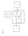
- FIG. 1 shows a schematic illustration of an organic electroluminescent device according to one embodiment of the invention.
- the organic electroluminescent device is embodied as an organic light emitting electrochemical cell 100 and comprises a substrate 1, a first electrode 2 arranged on the substrate 1, a functional organic layer 3 arranged on the first electrode 2, a second electrode 4 arranged on the organic functional layer 3 and an encapsulation 5 arranged on the second electrode 4.
- "Arranged on” means in this case that the layers and/or elements are directly mechanically and/or electrically connected to each other.
- the functional organic layer 3 comprises an organic semiconductor including an ionic transition metal complex having a band gap (not shown).
- the organic electroluminescent device 100 works in two modes, a pre-biasing mode and operation mode, wherein a pre-biasing mode comprises applying a first voltage being a constant value less than and/or equal to the band gap to the first and the second electrode and an operation mode comprises applying a second voltage being higher than the band gap to the first and the second electrode (not shown).
- a pre-biasing mode comprises applying a first voltage being a constant value less than and/or equal to the band gap to the first and the second electrode
- an operation mode comprises applying a second voltage being higher than the band gap to the first and the second electrode (not shown).
- the electromagnetic radiation 6 can be emitted through the substrate 1 ("bottom emitter").
- Organic light-emitting electrochemical cells have been prepared with the following configuration: ITO / 100nm PEDOT:PSS / 100 nm EML/ 150 nm Al, wherein ITO is indium tin oxide, PEDOT:PSS is poly(3,4-ethylenedioxythiophene) poly(styrenesulfonate).
- the layers of PEDOT:PSS and EML have been sequentially deposited on the ITO-glass anode via spin-coating from solution, whereas the Al cathode has been thermally evaporated.
- FIG. 2 shows an initial luminance L I in cd/m 2 as a function of a pre-biasing-time t B in hour h and a turn-on time T 200 in min as a function of the pre-biasing-time t B in hour h at a constant first voltage of 2 V.
- T 200 means the time to reach a luminance of 200 cd/m 2 . It is clearly apparent, that the turn-on time T 200 can be significantly reduced by simply increasing the pre-basing time t B for a fixed first voltage (2 V), which is accompanied with a simultaneous increase in the initial luminance.
- the organic electroluminescent device After 25 h of pre-biasing, for example, after switching to the operation mode, the organic electroluminescent device shows an initial luminance of more than 200 cd/m 2 . This is comparable to the brightness of standard television screens. Moreover, the initial luminance reaches a saturation value of 350 cd/m 2 by further increasing of the pre-biasing time t B . This value is comparable to the backlight illumination in LCD displays.
- Pre-biasing-time t B means here and in the following the time period of the pre-biasing mode.
- Figure 3 shows a luminance L in cd/m 2 as a function of time t in hour h at a constant first voltage of 2 V.
- the exemplary embodiments of this invention show the luminance L by a different pre-biasing time t B in h and a constant first voltage of 2 V. It seems that the stability of the organic electroluminescent device is unaffected from the pre-biasing mode and pre-biasing time t B . The decline of luminance is nearly the same for all organic electroluminescent devices, independent if they have been pre-biased or not as well as independent of the pie-biasing time.
- Figure 4 shows an initial luminance L I in cd/m 2 as a function of a first voltage U B in V and a turn-on time T 200 in min as a function of the first voltage U B in V at a constant pre-biasing time t B of 50 h.
- Figure 6 shows a luminance L in cd/m 2 as a function of time t in hour h of an exemplary embodiment E1 and a comparative embodiment V3.
- a potential application of the method of operating an organic electroluminescent device according to the invention is to stabilize or even maintain the initial organic electroluminescent device condition in the "off-state" or pre-biasing mode.
- the organic electroluminescent device relaxes during the off-period and approaches its pristine condition.
- This behavior of the comparative embodiment V3 is exemplarily depicted in Fig. 6 .
- the organic electroluminescent device After a pre-biasing mode of applying a first voltage of 2V for 25h, the organic electroluminescent device has been operated with an AC voltage signal of 2V/8V at 1 kHz for 2h and thereafter the operation mode has been paused for 5h. The last two cycles have been repeated several times.
- Figure 7 shows a current density d in mA/cm 2 as a function of time t in hour h.
- Figure 8 shows the power consumption P in W as a function of time t in hour h.
- the first voltage is 2 V for an OLEEC with an active area of 4 mm 2 .
- OLEECs in high quality thin films in combination with the above demonstrated pre-biasing principle enables OLEECs to be introduced as possible sources for flat and large-area lighting applications, with immediate turn-on and fast switching between the on- and off-state.
- Figures 9 to 11 show schematic illustrations of a method of operating an organic electroluminescent device according to one embodiment of the invention.
- Figure 9 shows a simple schematic illustration.
- Figure 10 shows a detailed schematic illustration of Figure 9 .
- Figure 11 shows an electrical circuit for the detailed schematic illustration of Figure 10 .
- Figures 9 and/or 10 show a power supply A, which can be a device that supplies electric power to one or more electric loads.
- the power supply A can be a battery, DC power supply, AC power supply, linear regulated power supply, AC/DC supply, switched-mode power supply, programmable power supply, uninterruptible power supply or voltage multipliers.
- the simplest on/off switch has one set of contacts (single pole) and one switching position which conducts (single throw).
- the switch mechanism has two positions: open (off) and closed (on). This simple on/off switch can be used to switch the power supply A to a circuit.
- a controlling unit C can electronically modify the power supply A.
- the controlling unit C comprises a voltage source for the first voltage E and a switch for switching between the operation mode and the pre-biasing mode F.
- the organic electroluminescent device is an organic light emitting electrochemical cell (OLEEC).
- OLED organic light emitting electrochemical cell
- the power supply A e.g. the common line voltage
- the transfer of the input signal from the power supply A to the organic electroluminescent device is controlled by an on/off switch B, whereas a controlling circuit C, which in principle also acts as a switch, differentiates between the operation mode and the pre-biasing mode.
- a proper electrical controlling unit C has to be designed, which satisfies two essential requirements: On the one hand the controlling unit C has to pre-bias the organic electroluminescent device and keep it at the desired constant potential in the "off-state” or pre-biasing mode and on the other hand it has to drive the organic electroluminescent device when switching to the "on-state” or operation mode.
- V L means in figure 11 a line voltage, which is the potential difference between two lines of different phases. This means there can be actually 3 line voltages on a three-phase system; A-B, A-C, and B-C. For a balanced system, the three must be equal.
- a transformer T is shown in figure 11 , which is a device that transfers electrical energy or power from one circuit to another through inductively coupled conductors.
- D1 denotes in figure 11 a rectifier, which is an electrical device that converts alternating current (AC), which periodically reverses direction, to direct current (DC), which flows in only one direction.
- AC alternating current
- DC direct current
- a very low dropout voltage linear regulator which can operate with a very small input-output differential voltage.
- the regulator LT 3021 of Linear Technology can be used.
- the regulator R can operate from input supplies down to 0.9 V.
- This device can supply 500 mA of output current with a typical dropout voltage of 160 mV.
- the advantages of a low dropout voltage linear regulator include a lower minimum operating voltage, higher efficiency operation and lower heat dissipation.
- R1 and/or R2 denotes in figure 11 an ohmic resistor.
- the resistor R1 and/or R2 obeys Ohm's law.
- C EDLC denotes in figure 11 a charged capacitor or an electrolytic double-layer capacitor.
- the charged capacitor or electrolytic double-layer capacitor comprises dielectric materials, solid conductive polymers and/or polymerized organic semiconductors.
- U B denotes in figure 11 the first voltage.
- FIG 11 shows an electrical circuit for the schematic illustration of figure 10 .
- the transformer T and rectifier D1 can be used as a power supply A, which supplies the organic electroluminescent device with a sufficient input signal.
- the organic electroluminescent device works in two modes, which can be controlled by an on/off switcher B.
- the switch B In the case of the pre-biasing mode, the switch B is in the "off-state” and the first voltage U B is applied to the organic electroluminescent device.
- the low dropout voltage linear regulator R, ohmic resistors R1 and R2 and the charged capacitor C EDLC can generate and/or store the first voltage U B .
- the switch B In the case of the operation mode, the switch B is in the "on-state” and the second voltage U O is applied to the organic electroluminescent device.
- T C C EDLC ⁇ U B - U min I OLEEC
- I OLEEC is the first current through the organic electroluminescent device
- U B is the first voltage (e.g. 2V)
- U min is a defined lower voltage limit for the first voltage.
Landscapes
- Physics & Mathematics (AREA)
- Optics & Photonics (AREA)
- Engineering & Computer Science (AREA)
- Manufacturing & Machinery (AREA)
- Electroluminescent Light Sources (AREA)
Priority Applications (4)
| Application Number | Priority Date | Filing Date | Title |
|---|---|---|---|
| EP12177312.1A EP2688119A1 (de) | 2012-07-20 | 2012-07-20 | Organische elektrolumineszente Vorrichtung und Verfahren für den Betrieb einer organischen elektrolumineszenten Vorrichtung |
| PCT/EP2013/065221 WO2014013030A1 (en) | 2012-07-20 | 2013-07-18 | Organic electroluminescent device and a method of operating an organic electroluminescent device |
| US14/416,048 US20150208482A1 (en) | 2012-07-20 | 2013-07-18 | Organic Electroluminescent Device and a Method of Operating an Organic Electroluminescent Device |
| KR20157004336A KR20150038163A (ko) | 2012-07-20 | 2013-07-18 | 유기 전계발광 디바이스 및 유기 전계발광 디바이스를 동작시키는 방법 |
Applications Claiming Priority (1)
| Application Number | Priority Date | Filing Date | Title |
|---|---|---|---|
| EP12177312.1A EP2688119A1 (de) | 2012-07-20 | 2012-07-20 | Organische elektrolumineszente Vorrichtung und Verfahren für den Betrieb einer organischen elektrolumineszenten Vorrichtung |
Publications (1)
| Publication Number | Publication Date |
|---|---|
| EP2688119A1 true EP2688119A1 (de) | 2014-01-22 |
Family
ID=48794114
Family Applications (1)
| Application Number | Title | Priority Date | Filing Date |
|---|---|---|---|
| EP12177312.1A Withdrawn EP2688119A1 (de) | 2012-07-20 | 2012-07-20 | Organische elektrolumineszente Vorrichtung und Verfahren für den Betrieb einer organischen elektrolumineszenten Vorrichtung |
Country Status (4)
| Country | Link |
|---|---|
| US (1) | US20150208482A1 (de) |
| EP (1) | EP2688119A1 (de) |
| KR (1) | KR20150038163A (de) |
| WO (1) | WO2014013030A1 (de) |
Cited By (1)
| Publication number | Priority date | Publication date | Assignee | Title |
|---|---|---|---|---|
| CN109422777A (zh) * | 2017-08-24 | 2019-03-05 | 环球展览公司 | 有机电致发光材料和装置 |
Citations (1)
| Publication number | Priority date | Publication date | Assignee | Title |
|---|---|---|---|---|
| WO2010085180A1 (en) * | 2009-01-21 | 2010-07-29 | Ludvig Edman | Light-emitting electrochemical cell and system. use thereof and method for their operation |
Family Cites Families (7)
| Publication number | Priority date | Publication date | Assignee | Title |
|---|---|---|---|---|
| EP1817764A4 (de) * | 2004-11-30 | 2009-08-26 | Semiconductor Energy Lab | Anzeigeeinrichtung und ansteuervrfahren dafür, halbleitereinrichtung und elektronische vorrichtung |
| DE102008033929A1 (de) * | 2008-07-18 | 2010-01-21 | Siemens Aktiengesellschaft | Phosphoreszente Metallkomplexverbindung, Verfahren zur Herstellung dazu und strahlungsemittierendes Bauelement |
| JP5562327B2 (ja) * | 2009-05-22 | 2014-07-30 | パナソニック株式会社 | 表示装置及びその駆動方法 |
| DE102009031683A1 (de) * | 2009-07-03 | 2011-03-24 | Siemens Aktiengesellschaft | Phophoreszente Metallkomplexverbindung, Verfahren zur Herstellung dazu und strahlungsemittierendes Bauelement |
| DE102011006360A1 (de) * | 2011-03-29 | 2012-10-04 | Siemens Aktiengesellschaft | Komplexierung niedermolekularer Halbleiter für die Anwendung als Emitterkomplex in organischen lichtemitterenden elektrochemischen Zellen (OLEECs) |
| JP2014231477A (ja) * | 2011-09-21 | 2014-12-11 | シャープ株式会社 | アルコキシ基を有する遷移金属錯体、及びこれを用いた有機発光素子、色変換発光素子、光変換発光素子、有機レーザーダイオード発光素子、色素レーザー、表示装置、照明装置並びに電子機器 |
| JP5905270B2 (ja) * | 2012-01-18 | 2016-04-20 | 住友化学株式会社 | 金属錯体及び該金属錯体を含む発光素子 |
-
2012
- 2012-07-20 EP EP12177312.1A patent/EP2688119A1/de not_active Withdrawn
-
2013
- 2013-07-18 KR KR20157004336A patent/KR20150038163A/ko not_active Application Discontinuation
- 2013-07-18 US US14/416,048 patent/US20150208482A1/en not_active Abandoned
- 2013-07-18 WO PCT/EP2013/065221 patent/WO2014013030A1/en active Application Filing
Patent Citations (1)
| Publication number | Priority date | Publication date | Assignee | Title |
|---|---|---|---|---|
| WO2010085180A1 (en) * | 2009-01-21 | 2010-07-29 | Ludvig Edman | Light-emitting electrochemical cell and system. use thereof and method for their operation |
Non-Patent Citations (2)
| Title |
|---|
| RUBÉN D. COSTA ET AL: "Improving the Turn-On Time of Light-Emitting Electrochemical Cells without Sacrificing their Stability", CHEMISTRY OF MATERIALS, vol. 22, no. 4, 23 February 2010 (2010-02-23), pages 1288 - 1290, XP055048982, ISSN: 0897-4756, DOI: 10.1021/cm903549u * |
| STEPHAN VAN REENEN ET AL: "A Unifying Model for the Operation of Light-Emitting Electrochemical Cells", JOURNAL OF THE AMERICAN CHEMICAL SOCIETY, vol. 132, no. 39, 6 October 2010 (2010-10-06), pages 13776 - 13781, XP055049070, ISSN: 0002-7863, DOI: 10.1021/ja1045555 * |
Cited By (2)
| Publication number | Priority date | Publication date | Assignee | Title |
|---|---|---|---|---|
| CN109422777A (zh) * | 2017-08-24 | 2019-03-05 | 环球展览公司 | 有机电致发光材料和装置 |
| US11437591B2 (en) | 2017-08-24 | 2022-09-06 | Universal Display Corporation | Organic electroluminescent materials and devices |
Also Published As
| Publication number | Publication date |
|---|---|
| WO2014013030A1 (en) | 2014-01-23 |
| US20150208482A1 (en) | 2015-07-23 |
| KR20150038163A (ko) | 2015-04-08 |
Similar Documents
| Publication | Publication Date | Title |
|---|---|---|
| Yuan et al. | A cocktail of multiple cations in inorganic halide perovskite toward efficient and highly stable blue light-emitting diodes | |
| Zhou et al. | Manipulating ionic behavior with bifunctional additives for efficient sky‐blue perovskite light‐emitting diodes | |
| Peng et al. | Modified conducting polymer hole injection layer for high-efficiency perovskite light-emitting devices: enhanced hole injection and reduced luminescence quenching | |
| Dong et al. | Understanding the role of ion migration in the operation of perovskite light-emitting diodes by transient measurements | |
| Al Amin et al. | A comparative study via photophysical and electrical characterizations on interfacial and bulk exciplex-forming systems for efficient organic light-emitting diodes | |
| Bandiello et al. | Lithium salt additives and the influence of their counterion on the performances of light-emitting electrochemical cells | |
| EP3236507B1 (de) | Organische lichtemittierende vorrichtung | |
| CN101627485B (zh) | 具有铼掺杂剂的有机电子器件及其制造方法 | |
| Bideh et al. | Ruthenium phenanthroimidazole complexes for near infrared light-emitting electrochemical cells | |
| Shan et al. | Junction propagation in organometal halide perovskite–polymer composite thin films | |
| Roldan-Carmona et al. | Engineering charge injection interfaces in hybrid light-emitting electrochemical cells | |
| US20130069552A1 (en) | Organic electroluminescent device with space charge/voltage instability stabilization drive | |
| EP2733188B1 (de) | Organische elektrolumineszente vorrichtung und verfahren zur herstellung einer organischen elektrolumineszenten vorrichtung | |
| Zhang et al. | High performance organo-lead halide perovskite light-emitting diodes via surface passivation of phenethylamine | |
| Sun et al. | Effect of bathocuproine organic additive on optoelectronic properties of highly efficient methylammonium lead bromide perovskite light-emitting diodes | |
| CN104685653B (zh) | 用于制造光电子器件的方法和设备 | |
| US7981526B2 (en) | Display device | |
| Mardegan et al. | Stable Light‐Emitting Electrochemical Cells Using Hyperbranched Polymer Electrolyte | |
| Liu et al. | Electrolyte-gated light-emitting transistors: working principle and applications | |
| Payandeh et al. | High-brightness perovskite light-emitting diodes using a printable silver microflake contact | |
| Kumar et al. | Fusible Low Work Function Top Electrode for Vacuum-Free Perovskite Light-Emitting Diode Application: Role of OH-Terminated Sn Atoms at the Alloy Surface | |
| KR100476741B1 (ko) | 유기전자디바이스 및 비선형소자 | |
| EP2688119A1 (de) | Organische elektrolumineszente Vorrichtung und Verfahren für den Betrieb einer organischen elektrolumineszenten Vorrichtung | |
| Yang et al. | The addition of viologen in luminescent polymers for polymer light-emitting diodes | |
| Yudco et al. | Enhanced LED Performance by Ion Migration in Multiple Quantum Well Perovskite |
Legal Events
| Date | Code | Title | Description |
|---|---|---|---|
| PUAI | Public reference made under article 153(3) epc to a published international application that has entered the european phase |
Free format text: ORIGINAL CODE: 0009012 |
|
| AK | Designated contracting states |
Kind code of ref document: A1 Designated state(s): AL AT BE BG CH CY CZ DE DK EE ES FI FR GB GR HR HU IE IS IT LI LT LU LV MC MK MT NL NO PL PT RO RS SE SI SK SM TR |
|
| AX | Request for extension of the european patent |
Extension state: BA ME |
|
| 17P | Request for examination filed |
Effective date: 20140716 |
|
| RBV | Designated contracting states (corrected) |
Designated state(s): AL AT BE BG CH CY CZ DE DK EE ES FI FR GB GR HR HU IE IS IT LI LT LU LV MC MK MT NL NO PL PT RO RS SE SI SK SM TR |
|
| STAA | Information on the status of an ep patent application or granted ep patent |
Free format text: STATUS: THE APPLICATION IS DEEMED TO BE WITHDRAWN |
|
| 18D | Application deemed to be withdrawn |
Effective date: 20170201 |