EP2688069A2 - Devices and methods for reducing lubricant accumulation on sliders - Google Patents
Devices and methods for reducing lubricant accumulation on sliders Download PDFInfo
- Publication number
- EP2688069A2 EP2688069A2 EP13173888.2A EP13173888A EP2688069A2 EP 2688069 A2 EP2688069 A2 EP 2688069A2 EP 13173888 A EP13173888 A EP 13173888A EP 2688069 A2 EP2688069 A2 EP 2688069A2
- Authority
- EP
- European Patent Office
- Prior art keywords
- cavity
- slider
- features
- turbulence
- inducing
- Prior art date
- Legal status (The legal status is an assumption and is not a legal conclusion. Google has not performed a legal analysis and makes no representation as to the accuracy of the status listed.)
- Granted
Links
- 239000000314 lubricant Substances 0.000 title description 14
- 238000009825 accumulation Methods 0.000 title description 6
- 238000000034 method Methods 0.000 title description 5
- 230000001939 inductive effect Effects 0.000 claims abstract description 33
- 230000007704 transition Effects 0.000 claims abstract description 33
- 238000011144 upstream manufacturing Methods 0.000 claims abstract description 17
- 230000003746 surface roughness Effects 0.000 claims description 4
- 238000000926 separation method Methods 0.000 description 4
- 238000003860 storage Methods 0.000 description 4
- 238000009792 diffusion process Methods 0.000 description 3
- 230000007423 decrease Effects 0.000 description 1
- 238000009826 distribution Methods 0.000 description 1
- 230000000694 effects Effects 0.000 description 1
- 238000005530 etching Methods 0.000 description 1
- 230000002452 interceptive effect Effects 0.000 description 1
- 238000004519 manufacturing process Methods 0.000 description 1
- 238000003801 milling Methods 0.000 description 1
- 239000000126 substance Substances 0.000 description 1
Images

Classifications
-
- G—PHYSICS
- G11—INFORMATION STORAGE
- G11B—INFORMATION STORAGE BASED ON RELATIVE MOVEMENT BETWEEN RECORD CARRIER AND TRANSDUCER
- G11B21/00—Head arrangements not specific to the method of recording or reproducing
- G11B21/16—Supporting the heads; Supporting the sockets for plug-in heads
- G11B21/20—Supporting the heads; Supporting the sockets for plug-in heads while the head is in operative position but stationary or permitting minor movements to follow irregularities in surface of record carrier
- G11B21/21—Supporting the heads; Supporting the sockets for plug-in heads while the head is in operative position but stationary or permitting minor movements to follow irregularities in surface of record carrier with provision for maintaining desired spacing of head from record carrier, e.g. fluid-dynamic spacing, slider
-
- G—PHYSICS
- G11—INFORMATION STORAGE
- G11B—INFORMATION STORAGE BASED ON RELATIVE MOVEMENT BETWEEN RECORD CARRIER AND TRANSDUCER
- G11B5/00—Recording by magnetisation or demagnetisation of a record carrier; Reproducing by magnetic means; Record carriers therefor
- G11B5/48—Disposition or mounting of heads or head supports relative to record carriers ; arrangements of heads, e.g. for scanning the record carrier to increase the relative speed
- G11B5/58—Disposition or mounting of heads or head supports relative to record carriers ; arrangements of heads, e.g. for scanning the record carrier to increase the relative speed with provision for moving the head for the purpose of maintaining alignment of the head relative to the record carrier during transducing operation, e.g. to compensate for surface irregularities of the latter or for track following
- G11B5/60—Fluid-dynamic spacing of heads from record-carriers
- G11B5/6005—Specially adapted for spacing from a rotating disc using a fluid cushion
- G11B5/6082—Design of the air bearing surface
Definitions
- Certain embodiments of the present invention are generally directed to devices and methods for reducing lubricant accumulation on sliders.
- a slider in certain embodiments, includes an air bearing surface having a cavity.
- the cavity includes transition features at an upstream side of the cavity to mitigate air flow expansion along the cavity. Turbulence-inducing features are positioned on the transition features.
- the transition features are steps.
- the slider further comprises transition features at a downstream side of the cavity.
- the slider further comprises turbulence-inducing features positioned on the transition features at the downstream side of the cavity.
- the turbulence-inducing features are protuberances.
- the turbulence-inducing features have a surface roughness greater than the rest of the bottom side of the slider.
- the slider further comprises turbulence-inducing features positioned on the cavity floor.
- the cavity is a sub-ambient cavity.
- the turbulence-inducing features are located on a bottom cavity surface and are textured.
- a slider comprising: a bottom side wherein a portion of the bottom side defines a cavity, the cavity including transition features at an upstream side of the cavity to mitigate air flow expansion along the cavity; and turbulence-inducing features positioned on the bottom side immediately upstream of the cavity.
- the slider further comprises transition features at a downstream side of the cavity.
- the transition features are steps.
- the slider further comprises turbulence-inducing features positioned on the transition features at the upstream side of the cavity.
- the slider further comprises turbulence-inducing features positioned on a floor of the cavity.
- the turbulence-inducing features are protuberances.
- the turbulence-inducing features are micro-cavities.
- the turbulence-inducing features have a surface roughness greater than the rest of the bottom side of the slider.
- Lubricants are used on rotatable storage media and sliders within disc drives to protect storage media and sliders from physical and chemical damage.
- Lubricants used for storage media can include bonded and non-bonded portions.
- the non-bonded (or mobile) portion of the lubricant replenishes regions on the media where the lubricant may have become depleted.
- the mobile portion also can migrate from the media to the slider and then accumulate at regions on the slider.
- One mechanism of media-to-slider lubricant transfer and accumulation is a result of suction cavities in slider designs utilizing sub-ambient pressure.
- the presence of a sub-ambient pressure cavity can cause a backflow in an upstream direction towards the cavity because pressure at the trailing edge of the slider is at ambient-by definition, a higher pressure.
- the backflow can combine with main flow to form regions of flow stagnation, that is, where flow is at or near zero. Transferred lubricant tends to accumulate at these flow stagnation points.
- accumulated lubricant can interfere with the slider's flying characteristics, causing read/write errors and/or reduced data throughput, among other things.
- FIG. 1 shows a profile of a portion of an air-bearing surface (ABS) of a slider 100 having a sub-ambient cavity 102.
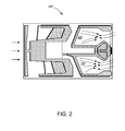
- FIG. 2 shows a bottom side of the slider 100 and cavity 102.
- ABS air-bearing surface
- FIG. 1 shows a profile of a portion of an air-bearing surface (ABS) of a slider 100 having a sub-ambient cavity 102.
- FIG. 2 shows a bottom side of the slider 100 and cavity 102.
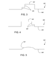
- FIG. 3 shows a profile of a portion of an air-bearing surface (ABS) of a slider 300.
- the slider 300 has a sub-ambient cavity 302 with transition features 304 at an upstream side of the cavity 302.
- the transition features 304 provide a gradual diffusion of main air flow along the slider 300.
- the transition features 304 may reduce boundary layer separation at slider walls and may reduce a loss of main flow momentum typically associated with previous cavity designs. Reduced separation and momentum loss in the cavity 302 decreases the chance of stagnation zones forming in the cavity 302.
- transition features can have an array of designs, such as steps, slopes, and curves, among other geometries.
- FIGS. 4-6 provide embodiments of slider designs using similar concepts described with respect to FIG. 3.
- FIG. 4 shows a profile of a portion of an ABS of a slider 400 having a sub-ambient cavity 402.
- the cavity 402 has transitions features at a downstream side of the cavity 402.
- the transition features 404 provide a gradual diffusion of backflow, thereby reducing the effect of backflow in the cavity 402.
- the transition features 404 are shown as steps, but can be other geometries.
- FIG. 5 shows a profile of a portion of an ABS of a slider 500 having a sub-ambient cavity 502 that is curved to provide gradual diffusion of main- and backflow.
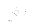
- FIG. 6 shows a profile of a portion of an ABS of a slider 600 having a sub-ambient cavity 602.
- the cavity 602 has transition features 604 at upstream and downstream sides-each side having features 604 with differing graduations of steps. Transition features can include any number or possibilities of geometries, although not all the possibilities are specifically
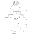
- FIG. 7 shows a profile of a portion of an ABS of a slider 700 having a sub-ambient cavity 702 with transition features 704.
- the transition features 704 have turbulence- or vortex-inducing features 706.
- the turbulence-inducing features 706 can be textured or roughened portions of the transition features 704. Textured features could include alternating grooves and ridges, for example. Roughened features could include portions of a surface having a higher surface roughness than the surrounding portions of the surface.
- the turbulence-inducing features 706 can be positioned at multiple locations within the cavity 702, for example, on the transition features 704 or on a cavity floor 708.
Landscapes
- Adjustment Of The Magnetic Head Position Track Following On Tapes (AREA)
- Magnetic Bearings And Hydrostatic Bearings (AREA)
- Bearings For Parts Moving Linearly (AREA)
- Coating Apparatus (AREA)
Abstract
Description
- Certain embodiments of the present invention are generally directed to devices and methods for reducing lubricant accumulation on sliders.
- In certain embodiments, a slider includes an air bearing surface having a cavity. The cavity includes transition features at an upstream side of the cavity to mitigate air flow expansion along the cavity. Turbulence-inducing features are positioned on the transition features.
- According to a first aspect of the present invention, there is provided a slider comprising: an air bearing surface having a cavity, the cavity including transition features at an upstream side of the cavity to mitigate air flow expansion along the cavity; and turbulence-inducing features positioned on the transition features at the upstream side of the cavity.
- Preferably, the transition features are steps.
- Preferably, the slider further comprises transition features at a downstream side of the cavity.
- It is further preferred that the slider further comprises turbulence-inducing features positioned on the transition features at the downstream side of the cavity.
- Preferably, the turbulence-inducing features are protuberances.
- Preferably, the turbulence-inducing features are micro-cavities.
- Preferably, the turbulence-inducing features have a surface roughness greater than the rest of the bottom side of the slider.
- Preferably, the slider further comprises turbulence-inducing features positioned on the cavity floor.
- Preferably, the cavity is a sub-ambient cavity.
- Preferably, the turbulence-inducing features are located on a bottom cavity surface and are textured.
- According to another aspect of the present invention, there is provided a slider comprising: a bottom side wherein a portion of the bottom side defines a cavity, the cavity including transition features at an upstream side of the cavity to mitigate air flow expansion along the cavity; and turbulence-inducing features positioned on the bottom side immediately upstream of the cavity.
- Preferably, the slider further comprises transition features at a downstream side of the cavity.
- Preferably, the transition features are steps.
- In this case, it is further preferred that the slider further comprises turbulence-inducing features positioned on the transition features at the upstream side of the cavity.
- Preferably, the slider further comprises turbulence-inducing features positioned on a floor of the cavity.
- Preferably, the turbulence-inducing features are protuberances.
- Preferably, the turbulence-inducing features are micro-cavities.
- Preferably, the turbulence-inducing features have a surface roughness greater than the rest of the bottom side of the slider.
-
-
FIG. 1 provides a side view of a portion of a slider profile. -
FIG. 2 provides a bottom view of the slider ofFIG. 1 . -
FIG. 3 provides a side view of a profile of a slider, in accordance with certain embodiments of the present disclosure. -
FIG. 4 provides a side view of a profile of a slider, in accordance with certain embodiments of the present disclosure. -
FIG. 5 provides a side view of a profile of a slider, in accordance with certain embodiments of the present disclosure. -
FIG. 6 provides a side view of a profile of a slider, in accordance with certain embodiments of the present disclosure. -
FIG. 7 provides a side view of a profile of a slider, in accordance with certain embodiments of the present disclosure. -
FIG. 8 provides a side view of a profile of a slider, in accordance with certain embodiments of the present disclosure. -
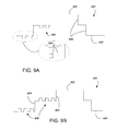
FIG. 9A provides a side view of a profile of a slider, in accordance with certain embodiments of the present disclosure. -
FIG. 9B provides a side view of a profile of a slider, in accordance with certain embodiments of the present disclosure. - The present disclosure relates to devices, systems, and methods for reducing lubricant accumulation on sliders. Lubricants are used on rotatable storage media and sliders within disc drives to protect storage media and sliders from physical and chemical damage. Lubricants used for storage media can include bonded and non-bonded portions. The non-bonded (or mobile) portion of the lubricant replenishes regions on the media where the lubricant may have become depleted. However, the mobile portion also can migrate from the media to the slider and then accumulate at regions on the slider.
- One mechanism of media-to-slider lubricant transfer and accumulation is a result of suction cavities in slider designs utilizing sub-ambient pressure. The presence of a sub-ambient pressure cavity can cause a backflow in an upstream direction towards the cavity because pressure at the trailing edge of the slider is at ambient-by definition, a higher pressure. The backflow can combine with main flow to form regions of flow stagnation, that is, where flow is at or near zero. Transferred lubricant tends to accumulate at these flow stagnation points. As a result, accumulated lubricant can interfere with the slider's flying characteristics, causing read/write errors and/or reduced data throughput, among other things.
- Some attempts to mitigate lubricant accumulation have utilized trenches at stagnation points that "trap" lubricant and limit lubricant from flowing back and forth through the region and interfering with read/write elements. However, these attempts do not attack the underlying problem: flow stagnation.
- Certain embodiments of the present disclosure are accordingly directed to devices and methods for reducing flow stagnation on sliders.
-
FIG. 1 shows a profile of a portion of an air-bearing surface (ABS) of aslider 100 having asub-ambient cavity 102.FIG. 2 shows a bottom side of theslider 100 andcavity 102. As theslider 100 flies above astorage medium 104, a main flow of air flows over the ABS from a leading edge (upstream) to a trailing edge (downstream). At the same time, some air flows in an opposite direction of the main flow, from the trailing edge towards the leading edge-the backflow. As the mainflow traverses the ABS and reaches the cavity 102 (seeFIG. 2 ), the airflow expands or diffuses into thecavity 102 across an upstreamvertical wall 106 of thecavity 102. This expansion can result in sudden and rapid deceleration of the mainflow and possibly separation of a boundary layer along walls of thecavity 102. The deceleration and separation can be exacerbated in the presence of the backflow across the trailing edge-a condition shown in bothFIGS. 1 and2 . As a result, the possibility of flow stagnation is increased, which also increases the possibility of lubricant accumulation in portions of the sub-ambient cavity. -
FIG. 3 shows a profile of a portion of an air-bearing surface (ABS) of aslider 300. Theslider 300 has asub-ambient cavity 302 withtransition features 304 at an upstream side of thecavity 302. Thetransition features 304 provide a gradual diffusion of main air flow along theslider 300. As such, thetransition features 304 may reduce boundary layer separation at slider walls and may reduce a loss of main flow momentum typically associated with previous cavity designs. Reduced separation and momentum loss in thecavity 302 decreases the chance of stagnation zones forming in thecavity 302. As shown inFIG. 3 and following figures, transition features can have an array of designs, such as steps, slopes, and curves, among other geometries. -
FIGS. 4-6 provide embodiments of slider designs using similar concepts described with respect toFIG. 3. FIG. 4 shows a profile of a portion of an ABS of aslider 400 having asub-ambient cavity 402. Thecavity 402 has transitions features at a downstream side of thecavity 402. Here, the transition features 404 provide a gradual diffusion of backflow, thereby reducing the effect of backflow in thecavity 402. The transition features 404 are shown as steps, but can be other geometries.FIG. 5 shows a profile of a portion of an ABS of aslider 500 having asub-ambient cavity 502 that is curved to provide gradual diffusion of main- and backflow.FIG. 6 shows a profile of a portion of an ABS of aslider 600 having asub-ambient cavity 602. Thecavity 602 has transition features 604 at upstream and downstream sides-eachside having features 604 with differing graduations of steps. Transition features can include any number or possibilities of geometries, although not all the possibilities are specifically shown in the figures. -
FIG. 7 shows a profile of a portion of an ABS of aslider 700 having asub-ambient cavity 702 with transition features 704. The transition features 704 have turbulence- or vortex-inducingfeatures 706. The turbulence-inducingfeatures 706 can be textured or roughened portions of the transition features 704. Textured features could include alternating grooves and ridges, for example. Roughened features could include portions of a surface having a higher surface roughness than the surrounding portions of the surface. The turbulence-inducingfeatures 706 can be positioned at multiple locations within thecavity 702, for example, on the transition features 704 or on acavity floor 708. As air flows over the turbulence-inducingfeatures 706, the boundary layer of the flow becomes turbulent, which facilitates large-scale momentum transfer from high-shear layers close to a rotating disc to layers close to walls of thecavity 702. This momentum transfer permits the momentum of the main flow to prevail over a larger portion of thecavity 702 and therefore reduce the possibility of flow stagnation zones within thecavity 702.FIG. 8 shows a profile of a portion of an ABS of aslider 800 having asub-ambient cavity 802. Turbulence-inducingfeatures 804 are located directly upstream of thecavity 802 to induce turbulence of main flow as it enters thecavity 802. -
FIGS. 9A and 9B show a profile of portion of an ABS of aslider 900 having asub-ambient cavity 902 with transition features 904. Turbulence-inducing features are located directly upstream of the cavity and also located on the transition features 904. As shown inFIG. 9 , the turbulence-inducing areprotuberances 906. As shown in FIG. 10, the turbulence-inducing are micro-cavities 908. The turbulence-inducing features can be formed by milling or etching, among other methods used for slider manufacturing processes. The characteristics, geometries, and locations of the turbulence-inducing features can be optimized for different slider designs. For example, in certain embodiments and shown inFIG. 9B , the turbulence-inducing features are arranged in a randomized distribution to enhance turbulent mixing of the main flow within the cavity. - It is to be understood that even though numerous characteristics and advantages of various embodiments of the present invention have been set forth in the foregoing description, together with details of the structure and function of various embodiments of the invention, this detailed description is illustrative only, and changes may be made in detail, especially in matters of structure and arrangements of parts within the principles of the present invention to the full extent indicated by the broad general meaning of the terms in which the appended claims are expressed.
Claims (10)
- A slider (700, 900) comprising:an air bearing surface (ABS) having a cavity (702, 902), the cavity including transition features (704, 904) at an upstream side of the cavity to mitigate air flow expansion along the cavity; andturbulence-inducing features (706, 905) positioned on the transition features at the upstream side of the cavity, or positioned immediately upstream of the cavity.
- The slider of claim 1, wherein the transition features are steps.
- The slider of claim 1 or claim 2, further comprising transition features at a downstream side of the cavity.
- The slider of claim 3, further comprising turbulence-inducing features positioned on the transition features at the downstream side of the cavity.
- The slider of any one of the preceding claims, wherein the turbulence-inducing features are protuberances.
- The slider of any one of claim 1 to 4, wherein the turbulence-inducing features are micro-cavities.
- The slider of any one of the preceding claims, wherein the turbulence-inducing features have a surface roughness greater than the rest of a bottom side of the slider.
- The slider of any one of the preceding claims, further comprising:turbulence-inducing features positioned on the cavity floor (708).
- The slider of any one of the preceding claims, wherein the cavity is a sub-ambient cavity.
- The slider of claim 1, wherein the turbulence-inducing features are located on a bottom cavity surface and are textured.
Applications Claiming Priority (1)
| Application Number | Priority Date | Filing Date | Title |
|---|---|---|---|
| US13/553,072 US8810967B2 (en) | 2012-07-19 | 2012-07-19 | Devices and methods for reducing lubricant accumulation on sliders |
Publications (3)
| Publication Number | Publication Date |
|---|---|
| EP2688069A2 true EP2688069A2 (en) | 2014-01-22 |
| EP2688069A3 EP2688069A3 (en) | 2014-06-25 |
| EP2688069B1 EP2688069B1 (en) | 2017-06-21 |
Family
ID=48740887
Family Applications (1)
| Application Number | Title | Priority Date | Filing Date |
|---|---|---|---|
| EP13173888.2A Not-in-force EP2688069B1 (en) | 2012-07-19 | 2013-06-26 | Devices and methods for reducing lubricant accumulation on sliders |
Country Status (5)
| Country | Link |
|---|---|
| US (1) | US8810967B2 (en) |
| EP (1) | EP2688069B1 (en) |
| JP (1) | JP5675907B2 (en) |
| KR (1) | KR101477551B1 (en) |
| CN (1) | CN103578484B (en) |
Families Citing this family (9)
| Publication number | Priority date | Publication date | Assignee | Title |
|---|---|---|---|---|
| JP2014026692A (en) * | 2012-07-25 | 2014-02-06 | Toshiba Corp | Magnetic head, head gimbal assembly provided with the same and disk device |
| US20160148631A1 (en) * | 2014-11-26 | 2016-05-26 | Seagate Technology Llc | Slider with micro-patterned coating |
| US9190090B1 (en) | 2014-12-24 | 2015-11-17 | Western Digital (Fremont), Llc | Multi step lube blocking air bearing area configuration |
| US9940960B2 (en) * | 2016-05-24 | 2018-04-10 | Sae Magnetics (Hk) Ltd. | Air-bearing design for hydrocarbon and lube pick-up improvements in hard disk drive (HDD) |
| US10796721B1 (en) | 2018-04-10 | 2020-10-06 | Seagate Technology Llc | Advanced air bearing slider |
| US10811046B2 (en) * | 2018-07-12 | 2020-10-20 | Sae Magnetics (H.K.) Ltd. | Air-bearing surface (ABS) design to reduce particle scratch risk |
| US11587584B1 (en) | 2022-02-28 | 2023-02-21 | Western Digital Technologies, Inc. | Slider air bearing design with ultra-low pressure for low power-consumption data storage devices |
| US11587583B1 (en) * | 2022-02-28 | 2023-02-21 | Western Digital Technologies, Inc. | Slider air bearing design with roughened leading edge shallow step for enhanced particle robustness |
| JP2023170917A (en) * | 2022-05-20 | 2023-12-01 | 株式会社東芝 | Magnetic head and magnetic disk device equipped with the same |
Family Cites Families (29)
| Publication number | Priority date | Publication date | Assignee | Title |
|---|---|---|---|---|
| JPS5888872A (en) * | 1981-11-20 | 1983-05-27 | Nec Corp | Floating head slider using negative pressure |
| JPH02156491A (en) * | 1988-12-08 | 1990-06-15 | Mitsubishi Electric Corp | Magnetic recorder |
| US5853959A (en) | 1996-08-09 | 1998-12-29 | Seagate Technology, Inc. | Method of fabricating a contoured slider surface feature with a single mask |
| WO1998021716A1 (en) * | 1996-11-13 | 1998-05-22 | Seagate Technology, Inc. | Disc head slider having surface discontinuities to minimize fly stiction |
| JPH10172125A (en) * | 1996-12-09 | 1998-06-26 | Alps Electric Co Ltd | Magnetic head, magnetic recording and reproducing device having the magnetic head and production of the magnetic head |
| JPH11144219A (en) * | 1997-11-11 | 1999-05-28 | Teac Corp | Magnetic head |
| US6212032B1 (en) * | 1998-02-18 | 2001-04-03 | Samsung Electronics Co., Ltd. | Pseudo contact negative pressure air bearing slider with divided negative pressure pockets |
| US6356405B1 (en) | 1998-05-22 | 2002-03-12 | Seagate Technology Llc | Lubricant control in disc drive |
| US6483667B1 (en) * | 1998-07-21 | 2002-11-19 | Seagate Technology Llc | Self-loading disc head slider having multiple steps approximating a leading taper |
| US6466410B2 (en) * | 1998-10-13 | 2002-10-15 | Seagate Technology Llc | Slider for a data storage device with head disc interface for contact starts and stops (“CSS”) |
| US6611400B1 (en) | 1999-01-22 | 2003-08-26 | Seagate Technology Llc | Texture structure for optimizing head disc interface |
| US6356412B1 (en) * | 1999-09-30 | 2002-03-12 | Read-Rite Corporation | Air bearing facilitating load/unload of a magnetic read/write head |
| US6515831B1 (en) * | 2000-01-11 | 2003-02-04 | Seagate Technology Llc | Disc head slider having leading and trailing channeled rails for enhanced damping |
| JP3990091B2 (en) * | 2000-04-13 | 2007-10-10 | 株式会社日立グローバルストレージテクノロジーズ | Magnetic head slider and magnetic disk device |
| US7417828B2 (en) * | 2000-07-11 | 2008-08-26 | Seagate Technology Llc | Bi-level cavity for a slider air-bearing surface |
| US6934122B2 (en) | 2000-07-28 | 2005-08-23 | Seagate Technology Llc | Disc head slider with sub-ambient pressure cavity bottom surfaces of differing depths |
| US6594113B2 (en) * | 2000-12-20 | 2003-07-15 | Seagate Technology Llc | Slider with furrows for flushing contaminants and lubricant |
| US6747847B2 (en) | 2001-01-10 | 2004-06-08 | Seagate Technology Llc | Self-flushing trench air bearing for improved slider flyability |
| US6809904B2 (en) * | 2001-09-27 | 2004-10-26 | Seagate Technology Llc | Disc head slider designs with particle flushing channels |
| US20030081352A1 (en) * | 2001-10-30 | 2003-05-01 | Rao Ram M. | Flow gate for slider level fly height or dynamic control |
| US6989966B2 (en) * | 2002-02-15 | 2006-01-24 | Seagate Technology Llc | Slider having plural leading step-level slots |
| US7255636B2 (en) * | 2005-06-16 | 2007-08-14 | Seagate Technology Llc | Hybrid burnishing head design for improved burnishing of disk media |
| JP2008021375A (en) * | 2006-07-13 | 2008-01-31 | Fujitsu Ltd | Magnetic head slider and magnetic disk apparatus |
| US7961433B2 (en) | 2008-02-29 | 2011-06-14 | Sae Magnetics (Hk) Ltd. | Air-bearing design for hard disk drive (HDD) applications |
| US8089729B2 (en) * | 2008-10-14 | 2012-01-03 | Hitachi Global Storage Technologies Netherlands B.V. | Slider with an air bearing surface and related topography |
| US8203805B2 (en) * | 2009-03-05 | 2012-06-19 | Hitachi Global Storage Technologies Netherlands B.V. | ABS with lubricant control trenches for hard disk drives |
| US8488278B2 (en) * | 2009-10-23 | 2013-07-16 | Seagate Technology Llc | Slider with improved robustness to particle contact |
| JP5570199B2 (en) * | 2009-12-14 | 2014-08-13 | エイチジーエスティーネザーランドビーブイ | Magnetic head slider |
| US8199437B1 (en) * | 2010-03-09 | 2012-06-12 | Western Digital (Fremont), Llc | Head with an air bearing surface having a particle fence separated from a leading pad by a continuous moat |
-
2012
- 2012-07-19 US US13/553,072 patent/US8810967B2/en not_active Expired - Fee Related
-
2013
- 2013-06-26 EP EP13173888.2A patent/EP2688069B1/en not_active Not-in-force
- 2013-07-18 JP JP2013149242A patent/JP5675907B2/en not_active Expired - Fee Related
- 2013-07-18 CN CN201310304073.5A patent/CN103578484B/en not_active Expired - Fee Related
- 2013-07-18 KR KR1020130084780A patent/KR101477551B1/en not_active Expired - Fee Related
Non-Patent Citations (1)
| Title |
|---|
| None |
Also Published As
| Publication number | Publication date |
|---|---|
| CN103578484B (en) | 2016-12-28 |
| US8810967B2 (en) | 2014-08-19 |
| JP5675907B2 (en) | 2015-02-25 |
| CN103578484A (en) | 2014-02-12 |
| US20140022672A1 (en) | 2014-01-23 |
| KR101477551B1 (en) | 2014-12-30 |
| KR20140011971A (en) | 2014-01-29 |
| EP2688069A3 (en) | 2014-06-25 |
| JP2014022035A (en) | 2014-02-03 |
| EP2688069B1 (en) | 2017-06-21 |
Similar Documents
| Publication | Publication Date | Title |
|---|---|---|
| US8810967B2 (en) | Devices and methods for reducing lubricant accumulation on sliders | |
| US9734854B2 (en) | Tape heads with sub-ambient pressure cavities | |
| WO2007119696A1 (en) | Blade | |
| US4984114A (en) | Flying head slider | |
| Wu et al. | Computational fluid dynamics analysis of blade tip clearances on hemodynamic performance and blood damage in a centrifugal ventricular assist device | |
| US8139323B2 (en) | Material deposition on transducing head | |
| Koyama et al. | Stabilizing and destabilizing effects of Coriolis force on two-dimensional laminar and turbulent boundary layers | |
| US20090219651A1 (en) | Air-bearing design for hard disk drive (HDD) applications | |
| US8593763B2 (en) | Preventing oil migration to slider fluid bearing surface | |
| US8089729B2 (en) | Slider with an air bearing surface and related topography | |
| US8094411B2 (en) | Slider with pockets in front of air bearing surface | |
| US8810968B2 (en) | Slider with lubricant control features | |
| US9940960B2 (en) | Air-bearing design for hydrocarbon and lube pick-up improvements in hard disk drive (HDD) | |
| CN100367360C (en) | Head sliders and disk drives | |
| AU2014309337B2 (en) | Read/write head with improved contact | |
| JP2010015652A (en) | Head slider and magnetic storage device | |
| Marchon et al. | Lubricant dynamics on a slider:“The waterfall effect” | |
| US20070025023A1 (en) | Magnetic head slider with suppressed flying height reduction and magnetic hard disk drive | |
| US20190189153A1 (en) | Slider gas-bearing surface designs with leading-edge pockets | |
| JPS63298879A (en) | Magnetic head slider and its manufacturing method | |
| US7236329B2 (en) | Head slider having extension rails to provide uniform flotation and magnetic disk device including the same | |
| Li et al. | Numerical simulation of the head/disk interface for bit patterned media | |
| Hua et al. | Air Bearing Features on Discrete Track Media | |
| JPH0414689A (en) | Floating head slider | |
| Li et al. | Intermolecular forces, surface roughness and air bearing design |
Legal Events
| Date | Code | Title | Description |
|---|---|---|---|
| PUAI | Public reference made under article 153(3) epc to a published international application that has entered the european phase |
Free format text: ORIGINAL CODE: 0009012 |
|
| 17P | Request for examination filed |
Effective date: 20130716 |
|
| AK | Designated contracting states |
Kind code of ref document: A2 Designated state(s): AL AT BE BG CH CY CZ DE DK EE ES FI FR GB GR HR HU IE IS IT LI LT LU LV MC MK MT NL NO PL PT RO RS SE SI SK SM TR |
|
| AX | Request for extension of the european patent |
Extension state: BA ME |
|
| RIN1 | Information on inventor provided before grant (corrected) |
Inventor name: RAMAKRISHNAN, NARAYANAN Inventor name: RAJASEKHARAN, AJAYKUMAR |
|
| PUAL | Search report despatched |
Free format text: ORIGINAL CODE: 0009013 |
|
| AK | Designated contracting states |
Kind code of ref document: A3 Designated state(s): AL AT BE BG CH CY CZ DE DK EE ES FI FR GB GR HR HU IE IS IT LI LT LU LV MC MK MT NL NO PL PT RO RS SE SI SK SM TR |
|
| AX | Request for extension of the european patent |
Extension state: BA ME |
|
| RIC1 | Information provided on ipc code assigned before grant |
Ipc: G11B 5/60 20060101AFI20140521BHEP |
|
| RBV | Designated contracting states (corrected) |
Designated state(s): AL AT BE BG CH CY CZ DE DK EE ES FI FR GB GR HR HU IE IS IT LI LT LU LV MC MK MT NL NO PL PT RO RS SE SI SK SM TR |
|
| 17Q | First examination report despatched |
Effective date: 20151120 |
|
| GRAP | Despatch of communication of intention to grant a patent |
Free format text: ORIGINAL CODE: EPIDOSNIGR1 |
|
| INTG | Intention to grant announced |
Effective date: 20170102 |
|
| GRAS | Grant fee paid |
Free format text: ORIGINAL CODE: EPIDOSNIGR3 |
|
| GRAA | (expected) grant |
Free format text: ORIGINAL CODE: 0009210 |
|
| AK | Designated contracting states |
Kind code of ref document: B1 Designated state(s): AL AT BE BG CH CY CZ DE DK EE ES FI FR GB GR HR HU IE IS IT LI LT LU LV MC MK MT NL NO PL PT RO RS SE SI SK SM TR |
|
| REG | Reference to a national code |
Ref country code: GB Ref legal event code: FG4D |
|
| REG | Reference to a national code |
Ref country code: CH Ref legal event code: EP |
|
| REG | Reference to a national code |
Ref country code: IE Ref legal event code: FG4D |
|
| REG | Reference to a national code |
Ref country code: AT Ref legal event code: REF Ref document number: 903590 Country of ref document: AT Kind code of ref document: T Effective date: 20170715 |
|
| REG | Reference to a national code |
Ref country code: DE Ref legal event code: R096 Ref document number: 602013022476 Country of ref document: DE |
|
| REG | Reference to a national code |
Ref country code: NL Ref legal event code: MP Effective date: 20170621 |
|
| PG25 | Lapsed in a contracting state [announced via postgrant information from national office to epo] |
Ref country code: LT Free format text: LAPSE BECAUSE OF FAILURE TO SUBMIT A TRANSLATION OF THE DESCRIPTION OR TO PAY THE FEE WITHIN THE PRESCRIBED TIME-LIMIT Effective date: 20170621 Ref country code: GR Free format text: LAPSE BECAUSE OF FAILURE TO SUBMIT A TRANSLATION OF THE DESCRIPTION OR TO PAY THE FEE WITHIN THE PRESCRIBED TIME-LIMIT Effective date: 20170922 Ref country code: NO Free format text: LAPSE BECAUSE OF FAILURE TO SUBMIT A TRANSLATION OF THE DESCRIPTION OR TO PAY THE FEE WITHIN THE PRESCRIBED TIME-LIMIT Effective date: 20170921 Ref country code: FI Free format text: LAPSE BECAUSE OF FAILURE TO SUBMIT A TRANSLATION OF THE DESCRIPTION OR TO PAY THE FEE WITHIN THE PRESCRIBED TIME-LIMIT Effective date: 20170621 Ref country code: HR Free format text: LAPSE BECAUSE OF FAILURE TO SUBMIT A TRANSLATION OF THE DESCRIPTION OR TO PAY THE FEE WITHIN THE PRESCRIBED TIME-LIMIT Effective date: 20170621 |
|
| REG | Reference to a national code |
Ref country code: LT Ref legal event code: MG4D |
|
| REG | Reference to a national code |
Ref country code: AT Ref legal event code: MK05 Ref document number: 903590 Country of ref document: AT Kind code of ref document: T Effective date: 20170621 |
|
| REG | Reference to a national code |
Ref country code: FR Ref legal event code: PLFP Year of fee payment: 5 |
|
| PG25 | Lapsed in a contracting state [announced via postgrant information from national office to epo] |
Ref country code: SE Free format text: LAPSE BECAUSE OF FAILURE TO SUBMIT A TRANSLATION OF THE DESCRIPTION OR TO PAY THE FEE WITHIN THE PRESCRIBED TIME-LIMIT Effective date: 20170621 Ref country code: RS Free format text: LAPSE BECAUSE OF FAILURE TO SUBMIT A TRANSLATION OF THE DESCRIPTION OR TO PAY THE FEE WITHIN THE PRESCRIBED TIME-LIMIT Effective date: 20170621 Ref country code: NL Free format text: LAPSE BECAUSE OF FAILURE TO SUBMIT A TRANSLATION OF THE DESCRIPTION OR TO PAY THE FEE WITHIN THE PRESCRIBED TIME-LIMIT Effective date: 20170621 Ref country code: BG Free format text: LAPSE BECAUSE OF FAILURE TO SUBMIT A TRANSLATION OF THE DESCRIPTION OR TO PAY THE FEE WITHIN THE PRESCRIBED TIME-LIMIT Effective date: 20170921 Ref country code: LV Free format text: LAPSE BECAUSE OF FAILURE TO SUBMIT A TRANSLATION OF THE DESCRIPTION OR TO PAY THE FEE WITHIN THE PRESCRIBED TIME-LIMIT Effective date: 20170621 |
|
| PG25 | Lapsed in a contracting state [announced via postgrant information from national office to epo] |
Ref country code: RO Free format text: LAPSE BECAUSE OF FAILURE TO SUBMIT A TRANSLATION OF THE DESCRIPTION OR TO PAY THE FEE WITHIN THE PRESCRIBED TIME-LIMIT Effective date: 20170621 Ref country code: CZ Free format text: LAPSE BECAUSE OF FAILURE TO SUBMIT A TRANSLATION OF THE DESCRIPTION OR TO PAY THE FEE WITHIN THE PRESCRIBED TIME-LIMIT Effective date: 20170621 Ref country code: AT Free format text: LAPSE BECAUSE OF FAILURE TO SUBMIT A TRANSLATION OF THE DESCRIPTION OR TO PAY THE FEE WITHIN THE PRESCRIBED TIME-LIMIT Effective date: 20170621 Ref country code: SK Free format text: LAPSE BECAUSE OF FAILURE TO SUBMIT A TRANSLATION OF THE DESCRIPTION OR TO PAY THE FEE WITHIN THE PRESCRIBED TIME-LIMIT Effective date: 20170621 Ref country code: EE Free format text: LAPSE BECAUSE OF FAILURE TO SUBMIT A TRANSLATION OF THE DESCRIPTION OR TO PAY THE FEE WITHIN THE PRESCRIBED TIME-LIMIT Effective date: 20170621 |
|
| REG | Reference to a national code |
Ref country code: CH Ref legal event code: PL |
|
| PG25 | Lapsed in a contracting state [announced via postgrant information from national office to epo] |
Ref country code: SM Free format text: LAPSE BECAUSE OF FAILURE TO SUBMIT A TRANSLATION OF THE DESCRIPTION OR TO PAY THE FEE WITHIN THE PRESCRIBED TIME-LIMIT Effective date: 20170621 Ref country code: PL Free format text: LAPSE BECAUSE OF FAILURE TO SUBMIT A TRANSLATION OF THE DESCRIPTION OR TO PAY THE FEE WITHIN THE PRESCRIBED TIME-LIMIT Effective date: 20170621 Ref country code: IT Free format text: LAPSE BECAUSE OF FAILURE TO SUBMIT A TRANSLATION OF THE DESCRIPTION OR TO PAY THE FEE WITHIN THE PRESCRIBED TIME-LIMIT Effective date: 20170621 Ref country code: ES Free format text: LAPSE BECAUSE OF FAILURE TO SUBMIT A TRANSLATION OF THE DESCRIPTION OR TO PAY THE FEE WITHIN THE PRESCRIBED TIME-LIMIT Effective date: 20170621 Ref country code: IS Free format text: LAPSE BECAUSE OF FAILURE TO SUBMIT A TRANSLATION OF THE DESCRIPTION OR TO PAY THE FEE WITHIN THE PRESCRIBED TIME-LIMIT Effective date: 20171021 |
|
| REG | Reference to a national code |
Ref country code: IE Ref legal event code: MM4A |
|
| REG | Reference to a national code |
Ref country code: DE Ref legal event code: R097 Ref document number: 602013022476 Country of ref document: DE |
|
| PG25 | Lapsed in a contracting state [announced via postgrant information from national office to epo] |
Ref country code: MC Free format text: LAPSE BECAUSE OF FAILURE TO SUBMIT A TRANSLATION OF THE DESCRIPTION OR TO PAY THE FEE WITHIN THE PRESCRIBED TIME-LIMIT Effective date: 20170621 |
|
| PLBE | No opposition filed within time limit |
Free format text: ORIGINAL CODE: 0009261 |
|
| STAA | Information on the status of an ep patent application or granted ep patent |
Free format text: STATUS: NO OPPOSITION FILED WITHIN TIME LIMIT |
|
| PG25 | Lapsed in a contracting state [announced via postgrant information from national office to epo] |
Ref country code: LI Free format text: LAPSE BECAUSE OF NON-PAYMENT OF DUE FEES Effective date: 20170630 Ref country code: CH Free format text: LAPSE BECAUSE OF NON-PAYMENT OF DUE FEES Effective date: 20170630 Ref country code: DK Free format text: LAPSE BECAUSE OF FAILURE TO SUBMIT A TRANSLATION OF THE DESCRIPTION OR TO PAY THE FEE WITHIN THE PRESCRIBED TIME-LIMIT Effective date: 20170621 Ref country code: IE Free format text: LAPSE BECAUSE OF NON-PAYMENT OF DUE FEES Effective date: 20170626 Ref country code: LU Free format text: LAPSE BECAUSE OF NON-PAYMENT OF DUE FEES Effective date: 20170626 |
|
| 26N | No opposition filed |
Effective date: 20180322 |
|
| REG | Reference to a national code |
Ref country code: FR Ref legal event code: PLFP Year of fee payment: 6 |
|
| REG | Reference to a national code |
Ref country code: BE Ref legal event code: MM Effective date: 20170630 |
|
| PG25 | Lapsed in a contracting state [announced via postgrant information from national office to epo] |
Ref country code: SI Free format text: LAPSE BECAUSE OF FAILURE TO SUBMIT A TRANSLATION OF THE DESCRIPTION OR TO PAY THE FEE WITHIN THE PRESCRIBED TIME-LIMIT Effective date: 20170621 Ref country code: BE Free format text: LAPSE BECAUSE OF NON-PAYMENT OF DUE FEES Effective date: 20170630 |
|
| PG25 | Lapsed in a contracting state [announced via postgrant information from national office to epo] |
Ref country code: MT Free format text: LAPSE BECAUSE OF NON-PAYMENT OF DUE FEES Effective date: 20170626 |
|
| PG25 | Lapsed in a contracting state [announced via postgrant information from national office to epo] |
Ref country code: HU Free format text: LAPSE BECAUSE OF FAILURE TO SUBMIT A TRANSLATION OF THE DESCRIPTION OR TO PAY THE FEE WITHIN THE PRESCRIBED TIME-LIMIT; INVALID AB INITIO Effective date: 20130626 |
|
| PGFP | Annual fee paid to national office [announced via postgrant information from national office to epo] |
Ref country code: DE Payment date: 20190515 Year of fee payment: 7 |
|
| PGFP | Annual fee paid to national office [announced via postgrant information from national office to epo] |
Ref country code: FR Payment date: 20190516 Year of fee payment: 7 |
|
| PG25 | Lapsed in a contracting state [announced via postgrant information from national office to epo] |
Ref country code: CY Free format text: LAPSE BECAUSE OF NON-PAYMENT OF DUE FEES Effective date: 20170621 |
|
| PGFP | Annual fee paid to national office [announced via postgrant information from national office to epo] |
Ref country code: GB Payment date: 20190524 Year of fee payment: 7 |
|
| PG25 | Lapsed in a contracting state [announced via postgrant information from national office to epo] |
Ref country code: MK Free format text: LAPSE BECAUSE OF FAILURE TO SUBMIT A TRANSLATION OF THE DESCRIPTION OR TO PAY THE FEE WITHIN THE PRESCRIBED TIME-LIMIT Effective date: 20170621 |
|
| PG25 | Lapsed in a contracting state [announced via postgrant information from national office to epo] |
Ref country code: TR Free format text: LAPSE BECAUSE OF FAILURE TO SUBMIT A TRANSLATION OF THE DESCRIPTION OR TO PAY THE FEE WITHIN THE PRESCRIBED TIME-LIMIT Effective date: 20170621 |
|
| PG25 | Lapsed in a contracting state [announced via postgrant information from national office to epo] |
Ref country code: PT Free format text: LAPSE BECAUSE OF FAILURE TO SUBMIT A TRANSLATION OF THE DESCRIPTION OR TO PAY THE FEE WITHIN THE PRESCRIBED TIME-LIMIT Effective date: 20170621 |
|
| PG25 | Lapsed in a contracting state [announced via postgrant information from national office to epo] |
Ref country code: AL Free format text: LAPSE BECAUSE OF FAILURE TO SUBMIT A TRANSLATION OF THE DESCRIPTION OR TO PAY THE FEE WITHIN THE PRESCRIBED TIME-LIMIT Effective date: 20170621 |
|
| REG | Reference to a national code |
Ref country code: DE Ref legal event code: R119 Ref document number: 602013022476 Country of ref document: DE |
|
| GBPC | Gb: european patent ceased through non-payment of renewal fee |
Effective date: 20200626 |
|
| PG25 | Lapsed in a contracting state [announced via postgrant information from national office to epo] |
Ref country code: GB Free format text: LAPSE BECAUSE OF NON-PAYMENT OF DUE FEES Effective date: 20200626 Ref country code: FR Free format text: LAPSE BECAUSE OF NON-PAYMENT OF DUE FEES Effective date: 20200630 |
|
| PG25 | Lapsed in a contracting state [announced via postgrant information from national office to epo] |
Ref country code: DE Free format text: LAPSE BECAUSE OF NON-PAYMENT OF DUE FEES Effective date: 20210101 |