EP2688002A1 - Design assistance device of network system - Google Patents
Design assistance device of network system Download PDFInfo
- Publication number
- EP2688002A1 EP2688002A1 EP11861121.9A EP11861121A EP2688002A1 EP 2688002 A1 EP2688002 A1 EP 2688002A1 EP 11861121 A EP11861121 A EP 11861121A EP 2688002 A1 EP2688002 A1 EP 2688002A1
- Authority
- EP
- European Patent Office
- Prior art keywords
- information
- design
- network system
- actual
- comparison
- Prior art date
- Legal status (The legal status is an assumption and is not a legal conclusion. Google has not performed a legal analysis and makes no representation as to the accuracy of the status listed.)
- Granted
Links
Images





Classifications
-
- H—ELECTRICITY
- H04—ELECTRIC COMMUNICATION TECHNIQUE
- H04L—TRANSMISSION OF DIGITAL INFORMATION, e.g. TELEGRAPHIC COMMUNICATION
- H04L41/00—Arrangements for maintenance, administration or management of data switching networks, e.g. of packet switching networks
- H04L41/12—Discovery or management of network topologies
-
- H—ELECTRICITY
- H04—ELECTRIC COMMUNICATION TECHNIQUE
- H04L—TRANSMISSION OF DIGITAL INFORMATION, e.g. TELEGRAPHIC COMMUNICATION
- H04L12/00—Data switching networks
- H04L12/28—Data switching networks characterised by path configuration, e.g. LAN [Local Area Networks] or WAN [Wide Area Networks]
- H04L12/40—Bus networks
- H04L12/40006—Architecture of a communication node
-
- H—ELECTRICITY
- H04—ELECTRIC COMMUNICATION TECHNIQUE
- H04L—TRANSMISSION OF DIGITAL INFORMATION, e.g. TELEGRAPHIC COMMUNICATION
- H04L41/00—Arrangements for maintenance, administration or management of data switching networks, e.g. of packet switching networks
- H04L41/08—Configuration management of networks or network elements
- H04L41/0866—Checking the configuration
-
- H—ELECTRICITY
- H04—ELECTRIC COMMUNICATION TECHNIQUE
- H04L—TRANSMISSION OF DIGITAL INFORMATION, e.g. TELEGRAPHIC COMMUNICATION
- H04L41/00—Arrangements for maintenance, administration or management of data switching networks, e.g. of packet switching networks
- H04L41/14—Network analysis or design
- H04L41/145—Network analysis or design involving simulating, designing, planning or modelling of a network
-
- H—ELECTRICITY
- H04—ELECTRIC COMMUNICATION TECHNIQUE
- H04L—TRANSMISSION OF DIGITAL INFORMATION, e.g. TELEGRAPHIC COMMUNICATION
- H04L12/00—Data switching networks
- H04L12/28—Data switching networks characterised by path configuration, e.g. LAN [Local Area Networks] or WAN [Wide Area Networks]
- H04L12/40—Bus networks
- H04L12/403—Bus networks with centralised control, e.g. polling
-
- H—ELECTRICITY
- H04—ELECTRIC COMMUNICATION TECHNIQUE
- H04L—TRANSMISSION OF DIGITAL INFORMATION, e.g. TELEGRAPHIC COMMUNICATION
- H04L41/00—Arrangements for maintenance, administration or management of data switching networks, e.g. of packet switching networks
- H04L41/08—Configuration management of networks or network elements
- H04L41/085—Retrieval of network configuration; Tracking network configuration history
- H04L41/0853—Retrieval of network configuration; Tracking network configuration history by actively collecting configuration information or by backing up configuration information
-
- H—ELECTRICITY
- H04—ELECTRIC COMMUNICATION TECHNIQUE
- H04L—TRANSMISSION OF DIGITAL INFORMATION, e.g. TELEGRAPHIC COMMUNICATION
- H04L61/00—Network arrangements, protocols or services for addressing or naming
- H04L61/50—Address allocation
- H04L61/5038—Address allocation for local use, e.g. in LAN or USB networks, or in a controller area network [CAN]
Definitions
- the invention relates to a design assistance device of a network system having a master device and a slave device.
- FA factory automation
- production facilities placed in a factory are controlled by an industrial network system that includes various types of slave devices which collects data of and conducts control on the production facilities and a master device which conducts central control on these slave devices.
- the industrial Ethernet referred to also as a manufacturing industrial Ethernet, is a network that has introduced Ethernet technologies and apparatuses to the FA field in various layers.
- Various associations have openly disclosed the standards of the industrial Ethernet, one of which is Ethernet for Control Automation Technology (EtherCAT: registered trademark) promoted by the EtherCAT Technology Group (ETG).
- a design assistance device editor provided as personal computer software or a dedicated system is utilized to design a network configuration (namely, specification of a model, connection order, and addresses and various parameters assigned to the slave devices). Then, after the network configuration is fixed, based on its design information, various programs configured to operate in the master device are designed and developed and an actual network system (actual machine) is assembled.
- the actual machine should preferably be assembled as designed.
- the configuration is changed due to addition of slave devices, shift in their connection order, and alteration of their addresses in order to solve problems and correct functions.
- Such changes in network configuration have an influence on developments of a master device program and, therefore, are desired to be reflected in the original design information as quickly as possible.
- changes and modifications of the design information should be reduced to a minimum. Conventionally, identification of portions to be changed and modification of the design information have all been performed manually and required a lot of manpower.
- Patent Document 1 proposes a mechanism that, if a new model of a PLC or slave device appears, a design assistance device reads an information file of the model such that models supported by an editor can be increased.
- Patent Document 2 proposes not a technology about industrial networks but a method for providing GUI display of information of troubles occurring on the network along with the network configuration information.
- the invention has been developed, and it is an object of the invention to provide a technology that assists the user in a manner such that he can easily compare a network configuration in accordance with a design and a network configuration of an actual machine to each other in a network system including a master device and a plurality of slave devices.
- the first aspect of the invention is a design assistance device of a network system including a master device and a plurality of slave devices, the design assistance device including: a design information storage section configured to store design information containing at least information of the slave devices and information of a topology in a network system in accordance with a design created by a user; an actual configuration information generation section configured to, based on information collected by the master device from the slave devices in an actual network system, generate actual configuration information containing at least the information of the slave devices and the information of the topology in the actual network system; a comparison section configured to compare the design information and the actual configuration information; and an output section configured to, based on results of comparison by the comparison section, generate a comparison screen indicating the respective configurations of the designed network system and the actual network system along with their commonalities and differences and outputting the comparison screen to a display device.
- a design information storage section configured to store design information containing at least information of the slave devices and information of a topology in a network system in accordance with a design created
- the design network configuration and the actual network configuration are compared to each other automatically, to present the results to the user as a comparison screen.
- the comparison screen the commonalities and differences of the designed network configuration and the actual network configuration are indicated. Therefore, the user can quickly and easily grasp alteration positions of the network configuration, and easily decide how the design information should be modified in accordance with an actual machine.
- the invention it is possible to assist the user in a manner such that he can easily compare a network configuration in accordance with a design and a network configuration of an actual machine to each other in a network system including a master device and a plurality of slave devices.
- design assistance device design assistance tool
- EtherCAT EtherCAT standard
- the application of the invention is not limited to it.
- the invention can be applied to any network system including a master device and a plurality of slave devices.
- an industrial network 100 is formed by connecting a master device 200 (programmable logic controller: PLC) and a plurality of slave devices 300 to each other directly or indirectly via a cable 400, a device-fitted I/O unit (internal bus) 500, or hub device 700.
- the slave devices 300 may be a power supply unit, a motor unit, a counter unit, an image unit, a communication unit, an I/O unit, etc.
- a management device 600 may be connected which is used by a user to set operations of the master device 200, display operation states of the industrial network system 100, and design a network system.
- the management device 600 includes a personal computer etc. in which a design assistance tool or a management tool is installed.
- the hub device 700 has an IN port connecting to the upstream side and an OUT port connecting to the downstream side as well as a plurality of branching ports X1, X2.
- the user can make a desired topology by interconnecting the devices as setting their order and branching by using the cable or the hub device.
- a branching structure can be made also by connecting not only the hub device but also the plurality of slave devices on the downstream side of the slave device.
- the hub device is also one type of the slave device, so that they are generally referred to as a slave device unless they need to be distinguished from each other in particular.
- a general Ethernet-standard cable can also be used as the cable 400 or the cable 400 can be manufactured using facilities for use in manufacturing of Ethernet-use apparatuses. Thus, the costs can be reduced.
- Such an industrial network system 100 is utilized as an FA system placed in, for example, a factory.
- the master device 200 transmits an information signal containing control data through the network, in accordance with a program or operations.
- the slave devices 300 In response to a request from the master device contained in the information signal, to the slave devices 300 performs device operations based on the received information signal and rewrites and returns the received information signal.
- Production in the factory accommodating the industrial network system 100 is achieved by the slave devices all sharing tasks in conjunction with each other when the master device controls contents and timing of their operations.
- the industrial network system 100 of the present embodiment may include three modes prepared as modes for communication between the master device 200 and the slave devices 300, namely a position address mode, a logical address mode, and a node address mode.
- a position address mode communication is performed by using position addresses which are determined by physical connection order as viewed from the master device, the position address mode being utilized in, for example, low-level communication processing such as collection of information of the slave devices all over the network.
- the logical address mode cyclic communication is performed by using data referred to as frames, the logical address mode being utilized in communication processing related to performing of tasks which require high-speed data transmission and real-time properties.
- master-to-slave communication is performed by using node addresses assigned by the master device 200 to the slave devices 300.
- the slave devices 300 each have an address value preset by the user beforehand, the address value being held in an involatile memory in each of the slave devices.
- the master device 200 reads the address values from the slave devices 300 upon actuation of the network and, in principle, assigns node addresses having the same values as those address values to the slave devices 300, respectively.
- the address as the set value will be hereinafter referred to as an "alias".
- the node address are statically assigned, so that communication can be performed independently of the state of the network, that is, the node addresses are not changed even if the network state changes. Therefore, this mode is utilized in a case of, such as, for example, communication processing related to monitoring or management of the slave devices, when event-type message communication in which a communication-partner slave device (node) has been identified is necessary.
- a design assistance tool which assists designing a network configuration by providing graphical display.
- the design assistance tool provides the user with an environment (editor) in which design tasks such as selection of a slave device model, connection order and connection ports (topology design), and node addresses and various types of parameters to be assigned to the slave devices can be easily performed by using a GUI indicated on a display of the management device 600.
- a design assistance device a group of the functions implemented by the design assistance tool of the management device 600 will be referred to as a design assistance device.
- the information of the network configuration created by the user by using the design assistance device is referenced when assembling an actual machine and, additionally, utilized in the design and developments of a program to be executed in the master device 200 and the maintenance after operations of the actual machine. Therefore, if the network configuration encounters a change in an assembly process of the actual machine, the change should preferably be reflected in the design information in the design assistance device as quickly as possible. Accordingly, the design assistance device of the present embodiment has a network configuration cross-check function configured to assist tasks to compare the designed network configuration and the actual machine's network configuration and modify the designed network configuration against the actual machine.
- FIG. 1 is a block diagram showing the functional configuration of portions related to the network configuration cross-check function in the design assistance device of the present embodiment.
- a design assistance device 50 has a storage portion 51, an actual configuration information generation portion 52, a comparison portion 53, a screen generation/output portion 54, and a merger processing portion 55.
- the design assistance device 50 include, as hardware, a general-purpose computer including a Central Processing Unit (CPU), a main storage device (memory), an auxiliary storage device (hardware), a display device, an input device (keyboard, mouse, etc.), and a communication IF.
- CPU Central Processing Unit
- main storage device main storage device
- auxiliary storage device hardware
- display device an input device (keyboard, mouse, etc.)
- keyboard, mouse, etc. etc.
- the functions 51 to 55 described above are realized when a program stored in the auxiliary storage device is loaded to the main storage device and executed by the CPU. Explanation of the functions other than the network configuration cross-check function will be omitted in
- the storage portion 51 is a function (design information storage section) that stores the information (referred to as "design information") of a network configuration in accordance with a design created by the design assistance device 50.
- the design information is data that describes profile information of the slave devices of a network system, slave connection information, and address information.
- the profile information is used to identify the model of the slave devices and contains, for example, a product code, a vendor ID, a revision number, etc. of the slave devices.
- the slave connection information is used to understand a connection configuration (topology) of the slave devices and contains, for example, information that identifies slave device connection-destination devices and ports.
- the address information is used to indicate the value of a node address assigned to the slave device.
- the slave information file contains, for example, the product code, the vendor ID, the revision number, the number of ports, the type of ports, etc.
- Fig. 3(A) schematically shows an example of the design information stored in the storage portion 51.
- the information of six slave devices is described in order of position addresses.
- the first slave device is identified by "product code: a1, vendor ID: A, revision number: 002 (a-1-A-002)" and connected to an "OUT" port of a device “MASTER” (master device) and has its node address set to "1".
- the second slave device is identified by "a3-A-000” and connected to an "internal" port of the device "a1-A-002” and has its node address set to "2".
- the third slave device and the subsequent the information that identifies their respective slave device models, connection destinations, and node addresses is described.
- the user himself can directly create and edit design information, in the design assistance device 50 of the present embodiment, if a network configuration is created by the user by using a GUI of the editor, such design information as shown in Fig. 3(A) is exported automatically.
- the actual configuration information generation portion 52 is a function (actual configuration information generation section) that generates information (referred to as "actual configuration information") of the network configuration of an actual machine.
- the actual configuration information is different from the design information created by the user as described above in that it is generated on the basis of information collected by the master device 200 from the slave devices 300 in the actual network system 100. Slave information collection processing by the master device 200 will be described later.
- Fig. 3(B) schematically shows an example of actual configuration information generated by the actual configuration information generation portion 52.
- the types of the information pieces contained in the actual configuration information are essentially the same as those contained in the design information.
- the comparison portion 53 is a function (comparison section) that compares the design information and the actual configuration information and extract their commonalities and differences.
- the screen generation/output portion 54 is a function (output section) that generates, based on the results of comparison by the comparison portion 53, a comparison screen indicating the designed network configuration and the actual machine's network configuration along with their commonalities and differences and outputs the comparison screen to the display device.
- the merger processing portion 55 is a function (selection section, modification section) that enables modifying the network configuration on the comparison screen. Operations of the comparison portion 53, the screen generation/output portion 54, and the merger processing portion 55 will be described later.
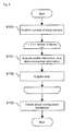
- Fig. 4 is a flowchart showing a flow of slave information collection processing (network scan processing).
- the master device reads profile information and slave connection information from each of the slave devices (step S101). Further, the master device reads an alias set in each of the slave devices from the slave devices (step S102). The processing in step S101 and that in step S102 are also performed in the position address mode.
- the data pieces collected by performing the processing pieces in steps S101 and S102 on all of the slave devices are sent to the design assistance device 50 (management device). Then, based on those data pieces, the actual configuration information generation/output portion 52 in the design assistance device 50 creates actual configuration information that indicates a network configuration of this network system (step S103). By those processing pieces, such actual configuration information as shown in Fig. 3(B) can be obtained. Although the present embodiment has created the actual configuration information at the actual configuration information generation portion 52 in the design assistance device 50, there is no problem if the actual configuration information is created in the master device only to send the resultant data from the master device to the actual configuration information generation portion 52.
- Fig. 5 is a flowchart showing a flow of network configuration comparison processing performed by the comparison portion 53 in the design assistance device 50.
- flags "AGREED”, “SHIFTED”, “ADDED”, and “DELETED” are given to the respective slave devices.
- the flags have the following meanings.
- the comparison portion 53 reads information of the i-th (0 ⁇ i ⁇ the number of the slaves contained in the actual configuration information) slave device (hereinafter simply referred to as "slave i") from the actual configuration information (step S200).
- the comparison portion 53 sequentially reads information of the j-th (0 ⁇ j ⁇ the number of the slaves contained in the design information) slave device (hereinafter simply referred to as "slave j") from the design configuration information (step S201) and checks whether the models and the addresses of the slaves i and j agree with each other, respectively (step S202) and then checks whether their respective connection-destination devices and ports agree with each other (step S203).
- the comparison portion 53 gives the flag "AGREED" to those slaves i and j (step S204). If a combination of the slaves i and j that agree with each other in model and address but not only in connection destination is found, the comparison portion 53 gives the flag "SHIFTED” to those slaves i and j (step S205). If no slave that agrees with the slave i in model and address is found in the design information, the comparison portion 53 gives the flag "DELETED" to the slave i (step S206).
- the comparison portion 53 checks whether there still exists any slave device to which no flag is given and, if any, gives the flag "DELETED" to the slave device (step S207).
- the present embodiment decides whether the models of the slave devices agree with each other in step S202.
- the present embodiment decides whether the models of the slave devices agree with each other in step S202.
- connection destination device and port
- the connection destination it is also decided in step S203 whether the connection destination (device and port) is different. This is because, if only the connection-destination port is changed despite that the connection-destination device may be the same in an industrial network system, the arrival destination or arrival order of data pieces sent from the master device changes, so that a trouble may occur in control or synchronization of the slave devices in some cases. In this respect, the situation is different from the case of a typical computer network, in which no matter to which port of the hub device the node is connected, the topology is not changed and no special trouble occurs.
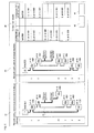
- Fig. 6 is one example of a comparison screen generated and output by the screen generation/output portion 54 in the design assistance device 50.
- a display portion 10 of a network configuration in accordance with a design a display portion 20 of an actual network configuration, and a display portion 30 of comparison results are provided in this order from the left.
- a topology tree of GUI is displayed, the topology tree having a network configuration in accordance with a design generated on the basis of design information and a slave information file.
- devices such as a master device 11 and slave devices 12a to 12f are displayed with icon components, the icon components being connected with lines 13 representing a cable or an internal bus.
- the lines 13 may have different colors or thicknesses depending on whether they represent the cable or the internal bus used for connection.
- branching ports X1, X2 also may well be represented by an icon component.
- the icon components are displayed in a manner such that each device may be displayed in each row, that is, a plurality of devices may not overlap with each other horizontally.
- Each row displays the value of a node address assigned to the slave device and profile information of the slave device in texts.
- the icon components for the devices in a series relationship in accordance with daisy chain connection are disposed in the same column and, if the topology branches off through the internal bus or the branching port, the icon components are disposed in the different columns.
- a topology tree of GUI is displayed, the topology tree having an actual machine's network configuration (a master device 21, slave devices 22a to 22f).
- the user can graphically grasp commonalities and differences between the designed network configuration and the actual machine's network configuration. For example, in the example in Fig. 6 , it is possible to recognize that the connection order is different between the position of the slave device 12c and that of the slave device 22e.
- the results of comparison by the comparison portion 53 are also displayed in the display portion 30 on the comparison screen.
- the display portion 30 it is possible to easily grasp commonalities and differences (addition/deletion/shifting) between the designed network configuration and the actual machine's network configuration.
- the merger processing portion 55 in the design assistance device 50 is a function that enables the user to modify the design information on the comparison screen. In the present embodiment, roughly three operation methods for modification are provided.
- the first method is to select a portion desired to be modified and press a reflection button 40 in the display portion 30 of the comparison results or in a topology tree of the designed network configuration or the actual machine's network configuration.
- Fig. 7 shows a state where portions corresponding to the slave devices 12c, 12d, and 22c are selected. If the reflection button 40 is pressed in this state, the merger processing portion 55 modifies the design information in accordance with contents of those selected portions and, based on the modification, the comparison screen is updated as shown in Fig. 8.
- Fig. 8 shows that the slave device 12c is deleted and the slave device 12d has the same node address of "3" as that of the slave device 22c, in the designed network configuration.
- the second method is to press a total reflection button 41. If the total reflection button 41 is pressed, the merger processing portion 55 modifies the design information in a manner such that the design information may be completely the same as the actual machine's network configuration.
- Fig. 9 shows an example of the comparison screen after total reflection. Fig. 9 shows that if the topology tree is the same, the comparison results all "AGREED".
- the third method is to modify the model or connection order of the slave devices and rewrite the node addresses by adding, deleting, and replacing (dragging and dropping) the icon components in a topology tree having a network configuration in accordance with a design.
- the contents displayed on the comparison screen are updated as the topology tree or the node address is modified.
- a network configuration in accordance with a design and an actual machine's network configuration are compared to each other automatically, presenting results of the comparison to the user as a comparison screen.
- results of the comparison are easily shown graphically. Therefore, the user can simply grasp portions of the network configuration to be changed quickly and also easily decide how to modify the design information in accordance with the actual machine.
- the modification contents are reflected in the design information, so that the user can simply modify the design information quickly.
- the comparison screen is updated as the information is modified, so that the modification task can be performed while confirming commonalities and differences in network configuration on the comparison screen.
- comparison screen and modification method described in the above embodiment is just one example.
- display of the comparison results is sufficient as long as its purpose is to display the commonalities and differences between the designed network configuration and the actual machine's network configuration.
- display of the comparison results may be incorporated into the topology tree by, for example, displaying the different portions' icon components and backgrounds in different colors such that the commonalities and differences in a displayed topology tree can be understood at first sight.
- the first aspect of the invention is a design assistance device of a network system including a master device and a plurality of slave devices, the design assistance device including: a design information storage section configured to store design information containing at least information of the slave devices and information of a topology in a network system in accordance with a design created by a user; an actual configuration information generation section configured to, based on information collected by the master device from the slave devices in an actual network system, generate actual configuration information containing at least the information of the slave devices and the information of the topology in the actual network system; a comparison section configured to compare the design information and the actual configuration information; and an output section configured to, based on results of comparison by the comparison section, generate a comparison screen indicating the respective configurations of the designed network system and the actual network system along with their commonalities and differences and outputting the comparison screen to a display device.
- a design information storage section configured to store design information containing at least information of the slave devices and information of a topology in a network system in accordance with a design created
- the design assistance device of the invention further includes a selection section configured to permit the user to select at least some of portions related to differences between the designed network system and the actual network system on the comparison screen; and a modification section configured to modify the design information in a manner such that the configuration of the portions selected by the selection section may be the same as that of the actual network.
- the selection section should preferably enable the user to select a plurality of the slave devices in the configuration of the actual network system on the comparison screen. It is thus possible to collectively command modification all over the plurality of slave devices, efficiently performing design information modification tasks.
- the output section updates the comparison screen in a manner such that commonalities and differences between the post-modification configuration of the designed network system and the actual network system may be indicated in accordance with modifications by the modification section.
- the modification task can be performed while confirming the commonalities and differences in network configuration on the comparison screen, to further improve operability and task efficiency.
- the information of the slave device contains information to identify a model of the slave device and the comparison section decides whether the model of the slave device contained in the design information and that contained in the actual configuration information agree with each other.
- the comparison section decides whether the model of the slave device contained in the design information and that contained in the actual configuration information agree with each other.
- the slave device information contains information to identify an address assigned to the slave device and the comparison section decides whether the address assigned to the slave device contained in the design information and that contained in the actual configuration information agree with each other. If the address assigned to the slave device in the actual machine is different from that at the time of design, a problem occurs in message communication in which a communication-partner node is identified such that a trouble may occur in monitoring, management, or control of the slave devices. Such a problem due to wrong addresses can be expected to be prevented beforehand by checking the address of the slave device also to enhance the reliabilities of the design information (coincidence with the actual machine) beforehand.
- the topology information contains information to identify connection-destination devices and ports of the slave device and the comparison section decided whether the slave device's connection-destination devices and ports contained in the design information and those contained in the actual configuration information agree with each other.
- the topology is not changed and no special trouble occurs.
- the arrival destination or arrival order of data pieces sent from the master device changes, so that a trouble may occur in control or synchronization of the slave devices in some cases.
- Such a problem due to a wrong destination connection can be expected to be prevented beforehand by checking the connection-destination devices and ports to enhance the reliabilities of the design information (coincidence with the actual machine) beforehand as in the case of the invention.
- the invention can be identified as a design assistance device including at least some of those sections and also can be identified as a program to cause a computer to function as the design assistance device or a computer-readable recording medium in which the program is recorded. Moreover, the present invention can be identified also as a design assistance method including at least some of processing pieces performed by those sections. Those processing pieces and sections can be combined arbitrarily as long as no technical conflicts occur.
- the second aspect of the invention is a program for assisting design of a network system including a master device and a plurality of slave devices and, if executed by a computer, causing the computer to function as: a design information storage section configured to store design information containing at least information of the slave devices and information of a topology in a network system in accordance with a design created by a user; an actual configuration information generation section configured to, based on information collected by the master device from the slave devices in an actual network system, generate actual configuration information containing at least the information of the slave devices and the information of the topology in the actual network system; a comparison section configured to compare the design information and the actual configuration information; and an output section configured to, based on results of comparison by the comparison section, generate a comparison screen indicating the respective configurations of the designed network system and the actual network system along with their commonalities and differences and outputting the comparison screen to a display device.
- a design information storage section configured to store design information containing at least information of the slave devices and information of a topology
- the third aspect of the invention is a design assistance method for assisting design of a network system including a master device and a plurality of slave devices and causing the computer to perform the steps of: storing design information containing at least information of the slave devices and information of a topology in a network system in accordance with a design created by a user; based on information collected by the master device from the slave devices in an actual network system, generating actual configuration information containing at least the information of the slave devices and the information of the topology in the actual network system; comparing the design information and the actual configuration information; and, based on results of comparison by the comparison section, generating a comparison screen indicating the respective configurations of the designed network system and the actual network system along with their commonalities and differences and outputting the comparison screen to a display device.
Landscapes
- Engineering & Computer Science (AREA)
- Computer Networks & Wireless Communication (AREA)
- Signal Processing (AREA)
- Data Exchanges In Wide-Area Networks (AREA)
- Small-Scale Networks (AREA)
Abstract
Description
- The invention relates to a design assistance device of a network system having a master device and a slave device.
- In factory automation (FA), production facilities placed in a factory are controlled by an industrial network system that includes various types of slave devices which collects data of and conducts control on the production facilities and a master device which conducts central control on these slave devices.
- Technologies have been developed for an industrial Ethernet (registered trademark) to which the Ethernet technologies are applied, as one example of the industrial network system for use in the FA field. The industrial Ethernet, referred to also as a manufacturing industrial Ethernet, is a network that has introduced Ethernet technologies and apparatuses to the FA field in various layers. Various associations have openly disclosed the standards of the industrial Ethernet, one of which is Ethernet for Control Automation Technology (EtherCAT: registered trademark) promoted by the EtherCAT Technology Group (ETG).
- When building this type of an industrial network system, first a design assistance device editor provided as personal computer software or a dedicated system is utilized to design a network configuration (namely, specification of a model, connection order, and addresses and various parameters assigned to the slave devices). Then, after the network configuration is fixed, based on its design information, various programs configured to operate in the master device are designed and developed and an actual network system (actual machine) is assembled.
- In this case, the actual machine should preferably be assembled as designed. Actually, however, in a process where the actual machine is assembled, there are many cases where the configuration is changed due to addition of slave devices, shift in their connection order, and alteration of their addresses in order to solve problems and correct functions. Such changes in network configuration have an influence on developments of a master device program and, therefore, are desired to be reflected in the original design information as quickly as possible. Moreover, to minimize corrections in the program under development, changes and modifications of the design information should be reduced to a minimum. Conventionally, identification of portions to be changed and modification of the design information have all been performed manually and required a lot of manpower.
- As technologies to present a network configuration to the user in a manner such that he can easily understand the network configuration, for example, those disclosed in
Patent Documents Patent Document 1 proposes a mechanism that, if a new model of a PLC or slave device appears, a design assistance device reads an information file of the model such that models supported by an editor can be increased. Further,Patent Document 2 proposes not a technology about industrial networks but a method for providing GUI display of information of troubles occurring on the network along with the network configuration information. -
- Patent Document 1:
JP 2010-272034 A, filed on Dec. 2, 2010 - Patent Document 2:
JP 2005-45840 A, filed on Feb. 17, 2005 - In view of the above, the invention has been developed, and it is an object of the invention to provide a technology that assists the user in a manner such that he can easily compare a network configuration in accordance with a design and a network configuration of an actual machine to each other in a network system including a master device and a plurality of slave devices.
- The first aspect of the invention is a design assistance device of a network system including a master device and a plurality of slave devices, the design assistance device including: a design information storage section configured to store design information containing at least information of the slave devices and information of a topology in a network system in accordance with a design created by a user; an actual configuration information generation section configured to, based on information collected by the master device from the slave devices in an actual network system, generate actual configuration information containing at least the information of the slave devices and the information of the topology in the actual network system; a comparison section configured to compare the design information and the actual configuration information; and an output section configured to, based on results of comparison by the comparison section, generate a comparison screen indicating the respective configurations of the designed network system and the actual network system along with their commonalities and differences and outputting the comparison screen to a display device.
- By the configuration, the design network configuration and the actual network configuration are compared to each other automatically, to present the results to the user as a comparison screen. On the comparison screen, the commonalities and differences of the designed network configuration and the actual network configuration are indicated. Therefore, the user can quickly and easily grasp alteration positions of the network configuration, and easily decide how the design information should be modified in accordance with an actual machine.
- By the invention, it is possible to assist the user in a manner such that he can easily compare a network configuration in accordance with a design and a network configuration of an actual machine to each other in a network system including a master device and a plurality of slave devices.
-
-
Fig. 1 is a block diagram showing a functional configuration related to a network configuration cross-check function in a design assistance device; -
Fig. 2 is an explanatory block diagram of a configuration example of an industrial network system; -
Fig. 3(A) is a table showing one example of design information andFig. 3(B) is a table showing one example of actual configuration information; -
Fig. 4 is a flowchart showing a flow of slave information collection processing; -
Fig. 5 is a flowchart showing a flow of network configuration comparison processing; -
Fig. 6 is a table showing one example of a comparison screen; -
Fig. 7 is a table showing a state where portions desired to be modified are selected on the comparison screen; -
Fig. 8 is a table showing a state the selected portions inFig. 7 are modified; and -
Fig. 9 is a table showing a state where a network configuration of an actual machine is totally reflected. - The following will describe a preferred embodiment of the invention with reference to the drawings. Although in the embodiment described below, a design assistance device (design assistance tool) in a network system compatible with the EtherCAT standard will be taken up, the application of the invention is not limited to it. The invention can be applied to any network system including a master device and a plurality of slave devices.
- First, a configuration example of an industrial network system will be described with reference to
Fig. 2 . In the figure, anindustrial network 100 is formed by connecting a master device 200 (programmable logic controller: PLC) and a plurality ofslave devices 300 to each other directly or indirectly via acable 400, a device-fitted I/O unit (internal bus) 500, orhub device 700. Theslave devices 300 may be a power supply unit, a motor unit, a counter unit, an image unit, a communication unit, an I/O unit, etc. To themaster device 200, amanagement device 600 may be connected which is used by a user to set operations of themaster device 200, display operation states of theindustrial network system 100, and design a network system. Themanagement device 600 includes a personal computer etc. in which a design assistance tool or a management tool is installed. - Assuming that the side of the master device is the upstream side, the
hub device 700 has an IN port connecting to the upstream side and an OUT port connecting to the downstream side as well as a plurality of branching ports X1, X2. The user can make a desired topology by interconnecting the devices as setting their order and branching by using the cable or the hub device. A branching structure can be made also by connecting not only the hub device but also the plurality of slave devices on the downstream side of the slave device. The hub device is also one type of the slave device, so that they are generally referred to as a slave device unless they need to be distinguished from each other in particular. - In an EtherCAT, a general Ethernet-standard cable can also be used as the
cable 400 or thecable 400 can be manufactured using facilities for use in manufacturing of Ethernet-use apparatuses. Thus, the costs can be reduced. - Such an
industrial network system 100 is utilized as an FA system placed in, for example, a factory. Themaster device 200 transmits an information signal containing control data through the network, in accordance with a program or operations. In response to a request from the master device contained in the information signal, to theslave devices 300 performs device operations based on the received information signal and rewrites and returns the received information signal. Production in the factory accommodating theindustrial network system 100 is achieved by the slave devices all sharing tasks in conjunction with each other when the master device controls contents and timing of their operations. - The
industrial network system 100 of the present embodiment may include three modes prepared as modes for communication between themaster device 200 and theslave devices 300, namely a position address mode, a logical address mode, and a node address mode. In the position address mode, communication is performed by using position addresses which are determined by physical connection order as viewed from the master device, the position address mode being utilized in, for example, low-level communication processing such as collection of information of the slave devices all over the network. In the logical address mode, cyclic communication is performed by using data referred to as frames, the logical address mode being utilized in communication processing related to performing of tasks which require high-speed data transmission and real-time properties. - In the node address mode, master-to-slave communication is performed by using node addresses assigned by the
master device 200 to theslave devices 300. Theslave devices 300 each have an address value preset by the user beforehand, the address value being held in an involatile memory in each of the slave devices. Themaster device 200 reads the address values from theslave devices 300 upon actuation of the network and, in principle, assigns node addresses having the same values as those address values to theslave devices 300, respectively. To clearly distinguish the address value as a set value preset to the slave device from the address value of the node address assigned to the slave device and utilized in communication, the address as the set value will be hereinafter referred to as an "alias". - Thus, the node address are statically assigned, so that communication can be performed independently of the state of the network, that is, the node addresses are not changed even if the network state changes. Therefore, this mode is utilized in a case of, such as, for example, communication processing related to monitoring or management of the slave devices, when event-type message communication in which a communication-partner slave device (node) has been identified is necessary.
- To design the
industrial network system 100, it is necessary to take into consideration a topology such as order in which the slave devices are connected and port numbers on the hub device. However, in contrast to the SEs or customer engineers, the common users do not always have expert knowledge or experiences. Accordingly, as one function of themanagement device 600, a design assistance tool is provided which assists designing a network configuration by providing graphical display. The design assistance tool provides the user with an environment (editor) in which design tasks such as selection of a slave device model, connection order and connection ports (topology design), and node addresses and various types of parameters to be assigned to the slave devices can be easily performed by using a GUI indicated on a display of themanagement device 600. Hereinafter, a group of the functions implemented by the design assistance tool of themanagement device 600 will be referred to as a design assistance device. - The information of the network configuration created by the user by using the design assistance device is referenced when assembling an actual machine and, additionally, utilized in the design and developments of a program to be executed in the
master device 200 and the maintenance after operations of the actual machine. Therefore, if the network configuration encounters a change in an assembly process of the actual machine, the change should preferably be reflected in the design information in the design assistance device as quickly as possible. Accordingly, the design assistance device of the present embodiment has a network configuration cross-check function configured to assist tasks to compare the designed network configuration and the actual machine's network configuration and modify the designed network configuration against the actual machine. -
Fig. 1 is a block diagram showing the functional configuration of portions related to the network configuration cross-check function in the design assistance device of the present embodiment. Adesign assistance device 50 has astorage portion 51, an actual configurationinformation generation portion 52, acomparison portion 53, a screen generation/output portion 54, and amerger processing portion 55. Thedesign assistance device 50 include, as hardware, a general-purpose computer including a Central Processing Unit (CPU), a main storage device (memory), an auxiliary storage device (hardware), a display device, an input device (keyboard, mouse, etc.), and a communication IF. Thefunctions 51 to 55 described above are realized when a program stored in the auxiliary storage device is loaded to the main storage device and executed by the CPU. Explanation of the functions other than the network configuration cross-check function will be omitted in the present specification. - The
storage portion 51 is a function (design information storage section) that stores the information (referred to as "design information") of a network configuration in accordance with a design created by thedesign assistance device 50. The design information is data that describes profile information of the slave devices of a network system, slave connection information, and address information. In this case, the profile information is used to identify the model of the slave devices and contains, for example, a product code, a vendor ID, a revision number, etc. of the slave devices. The slave connection information is used to understand a connection configuration (topology) of the slave devices and contains, for example, information that identifies slave device connection-destination devices and ports. The address information is used to indicate the value of a node address assigned to the slave device. Besides those design information pieces, a slave information file in which unique information of the slave devices is described for each model is stored in thestorage portion 51. The slave information file contains, for example, the product code, the vendor ID, the revision number, the number of ports, the type of ports, etc. -
Fig. 3(A) schematically shows an example of the design information stored in thestorage portion 51. In this example, the information of six slave devices is described in order of position addresses. The first slave device is identified by "product code: a1, vendor ID: A, revision number: 002 (a-1-A-002)" and connected to an "OUT" port of a device "MASTER" (master device) and has its node address set to "1". The second slave device is identified by "a3-A-000" and connected to an "internal" port of the device "a1-A-002" and has its node address set to "2". As for the third slave device and the subsequent, the information that identifies their respective slave device models, connection destinations, and node addresses is described. Although the user himself can directly create and edit design information, in thedesign assistance device 50 of the present embodiment, if a network configuration is created by the user by using a GUI of the editor, such design information as shown inFig. 3(A) is exported automatically. - The actual configuration
information generation portion 52 is a function (actual configuration information generation section) that generates information (referred to as "actual configuration information") of the network configuration of an actual machine. The actual configuration information is different from the design information created by the user as described above in that it is generated on the basis of information collected by themaster device 200 from theslave devices 300 in theactual network system 100. Slave information collection processing by themaster device 200 will be described later.Fig. 3(B) schematically shows an example of actual configuration information generated by the actual configurationinformation generation portion 52. The types of the information pieces contained in the actual configuration information are essentially the same as those contained in the design information. - The
comparison portion 53 is a function (comparison section) that compares the design information and the actual configuration information and extract their commonalities and differences. The screen generation/output portion 54 is a function (output section) that generates, based on the results of comparison by thecomparison portion 53, a comparison screen indicating the designed network configuration and the actual machine's network configuration along with their commonalities and differences and outputs the comparison screen to the display device. Further, themerger processing portion 55 is a function (selection section, modification section) that enables modifying the network configuration on the comparison screen. Operations of thecomparison portion 53, the screen generation/output portion 54, and themerger processing portion 55 will be described later. - Next, a description will be given in detail of operations of the network configuration cross-check function with reference to
Figs. 4 to 9 . -
Fig. 4 is a flowchart showing a flow of slave information collection processing (network scan processing). - First, the master device confirms the number of the slave devices that exist in a network (S100). For example, data (initial value = 0) sent from the master device is counted up in each of the slave devices to then return the results to the master device, enabling acquiring a total number of the slave devices. The processing is performed in the position address mode. In the example in
Fig. 2 , the slave count is "6". - Next, the master device reads profile information and slave connection information from each of the slave devices (step S101). Further, the master device reads an alias set in each of the slave devices from the slave devices (step S102). The processing in step S101 and that in step S102 are also performed in the position address mode.
- The data pieces collected by performing the processing pieces in steps S101 and S102 on all of the slave devices are sent to the design assistance device 50 (management device). Then, based on those data pieces, the actual configuration information generation/
output portion 52 in thedesign assistance device 50 creates actual configuration information that indicates a network configuration of this network system (step S103). By those processing pieces, such actual configuration information as shown inFig. 3(B) can be obtained. Although the present embodiment has created the actual configuration information at the actual configurationinformation generation portion 52 in thedesign assistance device 50, there is no problem if the actual configuration information is created in the master device only to send the resultant data from the master device to the actual configurationinformation generation portion 52. -
Fig. 5 is a flowchart showing a flow of network configuration comparison processing performed by thecomparison portion 53 in thedesign assistance device 50. In the processing, as results of the comparison, flags "AGREED", "SHIFTED", "ADDED", and "DELETED" are given to the respective slave devices. The flags have the following meanings. -
- "AGREED" ... Models, addresses, and connection destinations all agree with each other.
- "SHIFTED" ... The models and addresses agree with each other but only the connection destinations disagree with each other.
- "ADDED" ... Not contained in the design information but contained in the actual configuration information.
- "DELETED" ... Contained in the design information but not contained in the actual configuration information.
- The
comparison portion 53 reads information of the i-th (0 ≤ i < the number of the slaves contained in the actual configuration information) slave device (hereinafter simply referred to as "slave i") from the actual configuration information (step S200). Thecomparison portion 53 sequentially reads information of the j-th (0 ≤ j <the number of the slaves contained in the design information) slave device (hereinafter simply referred to as "slave j") from the design configuration information (step S201) and checks whether the models and the addresses of the slaves i and j agree with each other, respectively (step S202) and then checks whether their respective connection-destination devices and ports agree with each other (step S203). - If a combination of the slaves i and j that agree with each other in all of model, address, and connection destination is found, the
comparison portion 53 gives the flag "AGREED" to those slaves i and j (step S204). If a combination of the slaves i and j that agree with each other in model and address but not only in connection destination is found, thecomparison portion 53 gives the flag "SHIFTED" to those slaves i and j (step S205). If no slave that agrees with the slave i in model and address is found in the design information, thecomparison portion 53 gives the flag "DELETED" to the slave i (step S206). - After having performed the processing in steps S200 to S206 on all of the slave devices contained in the actual configuration information, the
comparison portion 53 checks whether there still exists any slave device to which no flag is given and, if any, gives the flag "DELETED" to the slave device (step S207). - In such a manner, the present embodiment decides whether the models of the slave devices agree with each other in step S202. Thus, it is possible to more strictly recognize agreement/disagreement in network configuration, assuring reliabilities of the design information (coincidence with the actual machine).
- Further, in the present embodiment, if only the addresses are difference, it is also decided that the properties are different ("ADDED" or "DELETED"). This is because, if an address different from that in accordance with a design is assigned to the slave device in an actual machine, a problem occurs in message communication in which a communication-partner node is identified, so that a trouble may occur in monitoring, management, or control of the slave devices. Such a problem due to wrong addresses can be prevented beforehand by checking the node addresses also to enhance the reliabilities of the design information (coincidence with the actual machine) beforehand.
- Further, in the present embodiment, it is also decided in step S203 whether the connection destination (device and port) is different. This is because, if only the connection-destination port is changed despite that the connection-destination device may be the same in an industrial network system, the arrival destination or arrival order of data pieces sent from the master device changes, so that a trouble may occur in control or synchronization of the slave devices in some cases. In this respect, the situation is different from the case of a typical computer network, in which no matter to which port of the hub device the node is connected, the topology is not changed and no special trouble occurs.
-
Fig. 6 is one example of a comparison screen generated and output by the screen generation/output portion 54 in thedesign assistance device 50. On the comparison screen, adisplay portion 10 of a network configuration in accordance with a design, adisplay portion 20 of an actual network configuration, and adisplay portion 30 of comparison results are provided in this order from the left. - As shown in
Fig. 6 , in thedisplay portion 10, a topology tree of GUI is displayed, the topology tree having a network configuration in accordance with a design generated on the basis of design information and a slave information file. In the topology tree, devices such as amaster device 11 andslave devices 12a to 12f are displayed with icon components, the icon components being connected withlines 13 representing a cable or an internal bus. In this case, thelines 13 may have different colors or thicknesses depending on whether they represent the cable or the internal bus used for connection. Further, in the case of aslave device 12b, which is a hub device, branching ports X1, X2 also may well be represented by an icon component. - In the topology tree, the icon components are displayed in a manner such that each device may be displayed in each row, that is, a plurality of devices may not overlap with each other horizontally. Each row displays the value of a node address assigned to the slave device and profile information of the slave device in texts. Further, in the topology tree, to enable intuitively understanding a topology hierarchy, the icon components for the devices in a series relationship in accordance with daisy chain connection are disposed in the same column and, if the topology branches off through the internal bus or the branching port, the icon components are disposed in the different columns. By thus inventively disposing the rows and the columns, the user can easily know the parent-child relationship of the slave devices in the network system, namely the connection order.
- Also in the
display portion 20 of the actual machine's network configurations, like in the case of thedisplay portion 10, a topology tree of GUI is displayed, the topology tree having an actual machine's network configuration (amaster device 21,slave devices 22a to 22f). By thus displaying the two topology trees side by side, the user can graphically grasp commonalities and differences between the designed network configuration and the actual machine's network configuration. For example, in the example inFig. 6 , it is possible to recognize that the connection order is different between the position of theslave device 12c and that of theslave device 22e. - To further help the user in understanding, the results of comparison by the
comparison portion 53 are also displayed in thedisplay portion 30 on the comparison screen. When looking at thedisplay portion 30, it is possible to easily grasp commonalities and differences (addition/deletion/shifting) between the designed network configuration and the actual machine's network configuration. - The
merger processing portion 55 in thedesign assistance device 50 is a function that enables the user to modify the design information on the comparison screen. In the present embodiment, roughly three operation methods for modification are provided. - The first method is to select a portion desired to be modified and press a
reflection button 40 in thedisplay portion 30 of the comparison results or in a topology tree of the designed network configuration or the actual machine's network configuration.Fig. 7 shows a state where portions corresponding to theslave devices reflection button 40 is pressed in this state, themerger processing portion 55 modifies the design information in accordance with contents of those selected portions and, based on the modification, the comparison screen is updated as shown inFig. 8. Fig. 8 shows that theslave device 12c is deleted and theslave device 12d has the same node address of "3" as that of theslave device 22c, in the designed network configuration. - The second method is to press a
total reflection button 41. If thetotal reflection button 41 is pressed, themerger processing portion 55 modifies the design information in a manner such that the design information may be completely the same as the actual machine's network configuration.Fig. 9 shows an example of the comparison screen after total reflection.Fig. 9 shows that if the topology tree is the same, the comparison results all "AGREED". - The third method is to modify the model or connection order of the slave devices and rewrite the node addresses by adding, deleting, and replacing (dragging and dropping) the icon components in a topology tree having a network configuration in accordance with a design. Of course, the contents displayed on the comparison screen are updated as the topology tree or the node address is modified. By this method, the user can easily modify the design information.
- As described above, in the design assistance device (network configuration cross-check function) of the present embodiment, a network configuration in accordance with a design and an actual machine's network configuration are compared to each other automatically, presenting results of the comparison to the user as a comparison screen. On the comparison screen, commonalities and differences between the design network configuration and the actual machine's network configuration are easily shown graphically. Therefore, the user can simply grasp portions of the network configuration to be changed quickly and also easily decide how to modify the design information in accordance with the actual machine.
- Further, only by simply selecting portions desired to be modified on the comparison screen, the modification contents are reflected in the design information, so that the user can simply modify the design information quickly. Moreover, it is also possible to modify only some of the portions or all of them collectively, so that the design information can be modified efficiently. Besides, the comparison screen is updated as the information is modified, so that the modification task can be performed while confirming commonalities and differences in network configuration on the comparison screen.
- Although in the above embodiment, the commonalities and differences between the designed network configuration and the actual machine's network configuration have been evaluated in four states of "AGREED", "SHIFTED", "ADDED", and "DELETED", it is just one example. For example, they may be evaluated by "AGREED" and "DIFFERENT" or in three states of "AGREED, "ADDED", and "DELETED" without checking the commonalities and differences in connection destination. Of course, the commonalities and differences may be evaluated in more detail in states of "ADDRESS CHANGED" and "MODEL CHANGED".
- Further, the comparison screen and modification method described in the above embodiment is just one example. For example, display of the comparison results is sufficient as long as its purpose is to display the commonalities and differences between the designed network configuration and the actual machine's network configuration. Conversely, display of the comparison results may be incorporated into the topology tree by, for example, displaying the different portions' icon components and backgrounds in different colors such that the commonalities and differences in a displayed topology tree can be understood at first sight.
- As described above, the first aspect of the invention is a design assistance device of a network system including a master device and a plurality of slave devices, the design assistance device including: a design information storage section configured to store design information containing at least information of the slave devices and information of a topology in a network system in accordance with a design created by a user; an actual configuration information generation section configured to, based on information collected by the master device from the slave devices in an actual network system, generate actual configuration information containing at least the information of the slave devices and the information of the topology in the actual network system; a comparison section configured to compare the design information and the actual configuration information; and an output section configured to, based on results of comparison by the comparison section, generate a comparison screen indicating the respective configurations of the designed network system and the actual network system along with their commonalities and differences and outputting the comparison screen to a display device.
- It is preferable that the design assistance device of the invention further includes a selection section configured to permit the user to select at least some of portions related to differences between the designed network system and the actual network system on the comparison screen; and a modification section configured to modify the design information in a manner such that the configuration of the portions selected by the selection section may be the same as that of the actual network. By the configuration, only by simply selecting portions desired to be modified on the comparison screen, the modification contents are reflected in the design information, so that the user can simply modify the design information quickly. In this case, the selection section should preferably enable the user to select a plurality of the slave devices in the configuration of the actual network system on the comparison screen. It is thus possible to collectively command modification all over the plurality of slave devices, efficiently performing design information modification tasks.
- It is preferable that the output section updates the comparison screen in a manner such that commonalities and differences between the post-modification configuration of the designed network system and the actual network system may be indicated in accordance with modifications by the modification section. By the configuration, the modification task can be performed while confirming the commonalities and differences in network configuration on the comparison screen, to further improve operability and task efficiency.
- It is preferable that the information of the slave device contains information to identify a model of the slave device and the comparison section decides whether the model of the slave device contained in the design information and that contained in the actual configuration information agree with each other. By thus checking also the slave device model, the commonalities and differences in network configuration can be evaluated more strictly, assuring the reliabilities of the design information (coincidence with the actual machine).
- It is also preferable that the slave device information contains information to identify an address assigned to the slave device and the comparison section decides whether the address assigned to the slave device contained in the design information and that contained in the actual configuration information agree with each other. If the address assigned to the slave device in the actual machine is different from that at the time of design, a problem occurs in message communication in which a communication-partner node is identified such that a trouble may occur in monitoring, management, or control of the slave devices. Such a problem due to wrong addresses can be expected to be prevented beforehand by checking the address of the slave device also to enhance the reliabilities of the design information (coincidence with the actual machine) beforehand.
- It is also preferable that the topology information contains information to identify connection-destination devices and ports of the slave device and the comparison section decided whether the slave device's connection-destination devices and ports contained in the design information and those contained in the actual configuration information agree with each other. In a typical computer network, no matter to which port of the hub device the node is connected, the topology is not changed and no special trouble occurs. In contrast, in an industrial network system, if only the connection-destination port is changed despite that connection-destination device may be the same, the arrival destination or arrival order of data pieces sent from the master device changes, so that a trouble may occur in control or synchronization of the slave devices in some cases. Such a problem due to a wrong destination connection can be expected to be prevented beforehand by checking the connection-destination devices and ports to enhance the reliabilities of the design information (coincidence with the actual machine) beforehand as in the case of the invention.
- The invention can be identified as a design assistance device including at least some of those sections and also can be identified as a program to cause a computer to function as the design assistance device or a computer-readable recording medium in which the program is recorded. Moreover, the present invention can be identified also as a design assistance method including at least some of processing pieces performed by those sections. Those processing pieces and sections can be combined arbitrarily as long as no technical conflicts occur.
- For example, the second aspect of the invention is a program for assisting design of a network system including a master device and a plurality of slave devices and, if executed by a computer, causing the computer to function as: a design information storage section configured to store design information containing at least information of the slave devices and information of a topology in a network system in accordance with a design created by a user; an actual configuration information generation section configured to, based on information collected by the master device from the slave devices in an actual network system, generate actual configuration information containing at least the information of the slave devices and the information of the topology in the actual network system; a comparison section configured to compare the design information and the actual configuration information; and an output section configured to, based on results of comparison by the comparison section, generate a comparison screen indicating the respective configurations of the designed network system and the actual network system along with their commonalities and differences and outputting the comparison screen to a display device.
- Further, the third aspect of the invention is a design assistance method for assisting design of a network system including a master device and a plurality of slave devices and causing the computer to perform the steps of: storing design information containing at least information of the slave devices and information of a topology in a network system in accordance with a design created by a user; based on information collected by the master device from the slave devices in an actual network system, generating actual configuration information containing at least the information of the slave devices and the information of the topology in the actual network system; comparing the design information and the actual configuration information; and, based on results of comparison by the comparison section, generating a comparison screen indicating the respective configurations of the designed network system and the actual network system along with their commonalities and differences and outputting the comparison screen to a display device.
-
- 50
- Design assistance device
- 51
- Storage portion
- 52
- Actual configuration information generation portion
- 53
- Comparison portion
- 54
- Screen generation/output portion
- 55
- Merger processing portion
- 100
- Industrial network system
- 200
- Master device
- 300
- Slave device
- 400
- Cable
- 500
- I/O unit
- 600
- Management device
- 700
- Hub device
- 10
- Display portion in network configuration in accordance with a design
- 11
- Icon component of master device
- 12a∼12f
- Icon component of slave device
- 13
- Line
- 20
- Display portion in network configuration of actual machine
- 21
- Icon component of master device
- 22a∼22f
- Icon component of slave device
- 30
- Display portion of comparison results
- 40
- Reflection button
- 41
- Total reflection button
Claims (9)
- A design assistance device of a network system including a master device and a plurality of slave devices, the design assistance device comprising:a design information storage section configured to store design information containing at least information of the slave devices and information of a topology in the network system in accordance with a design created by a user;an actual configuration information generation section configured to, based on information collected by the master device from the slave devices in an actual network system, generate actual configuration information containing at least the information of the slave devices and the information of the topology in the actual network system;a comparison section configured to compare the design information and the actual configuration information; andan output section configured to, based on results of comparison by the comparison section, generate a comparison screen indicating the respective configurations of the designed network system and the actual network system along with their commonalities and differences and outputting the comparison screen to a display device.
- The design assistance device according to claim 1, further comprising:a selection section configured to permit the user to select at least some of portions related to differences between the designed network system and the actual network system on the comparison screen; anda modification section configured to modify the design information in a manner such that the configuration of the portions selected by the selection section is the same as that of the actual network system.
- The design assistance device according to claim 2,
wherein the output section updates the comparison screen in a manner such that commonalities and differences between the post-modification configuration of the designed network system and the actual network system may be indicated in accordance with modifications by the modification section. - The design assistance device according to any one of claims 1 to 3, wherein
information of the slave device contains information to identify a model of the slave device; and
the comparison section decides whether the model of the slave device contained in the design information and that contained in the actual configuration information agree with each other. - The design assistance device according to any one of claims 1 to 4, wherein:the information of the slave device contains the information to identify an address assigned to the slave device; andthe comparison section decides whether the address assigned to the slave device contained in the design information and that contained in the actual configuration information agree with each other.
- The design assistance device according to any one of claims 1 to 5, wherein:the topology information contains information to identify connection-destination devices and ports of the slave device; andthe comparison section decides whether the slave device's connection-destination devices and ports contained in the design information and those contained in the actual configuration information agree with each other.
- A program for assisting design of a network system including a master device and a plurality of slave devices and, if executed by a computer, causing the computer to function as:a design information storage section configured to store design information containing at least information of the slave devices and information of a topology in a network system in accordance with a design created by a user;an actual configuration information generation section configured to, based on information collected by the master device from the slave devices in an actual network system, generate actual configuration information containing at least the information of the slave devices and the information of the topology in the actual network system;a comparison section configured to compare the design information and the actual configuration information; andan output section configured to, based on results of comparison by the comparison section, generate a comparison screen indicating the respective configurations of the designed network system and the actual network system along with their commonalities and differences and outputting the comparison screen to a display device.
- A computer-readable recording medium in which the program according to claim 7 is recorded.
- A design assistance method for assisting design of a network system including a master device and a plurality of slave devices and causing a computer to perform the steps of:storing design information containing at least information of the slave devices and information of a topology in a network system in accordance with a design created by a user;based on information collected by the master device from the slave devices in an actual network system, generating actual configuration information containing at least the information of the slave devices and the information of the topology in the actual network system;comparing the design information and the actual configuration information; and,based on results of comparison by the comparison section, generating a comparison screen indicating the respective configurations of the designed network system and the actual network system along with their commonalities and differences and outputting the comparison screen to a display device.
Applications Claiming Priority (2)
| Application Number | Priority Date | Filing Date | Title |
|---|---|---|---|
| JP2011056379A JP5120473B2 (en) | 2011-03-15 | 2011-03-15 | Network system design support device |
| PCT/JP2011/057035 WO2012124163A1 (en) | 2011-03-15 | 2011-03-23 | Design assistance device of network system |
Publications (3)
| Publication Number | Publication Date |
|---|---|
| EP2688002A1 true EP2688002A1 (en) | 2014-01-22 |
| EP2688002A4 EP2688002A4 (en) | 2014-10-15 |
| EP2688002B1 EP2688002B1 (en) | 2016-01-06 |
Family
ID=46830271
Family Applications (1)
| Application Number | Title | Priority Date | Filing Date |
|---|---|---|---|
| EP11861121.9A Revoked EP2688002B1 (en) | 2011-03-15 | 2011-03-23 | Design assistance device of a network system |
Country Status (5)
| Country | Link |
|---|---|
| US (1) | US9596124B2 (en) |
| EP (1) | EP2688002B1 (en) |
| JP (1) | JP5120473B2 (en) |
| CN (1) | CN103403720B (en) |
| WO (1) | WO2012124163A1 (en) |
Cited By (9)
| Publication number | Priority date | Publication date | Assignee | Title |
|---|---|---|---|---|
| CN107306403A (en) * | 2016-04-21 | 2017-10-31 | 富士通株式会社 | For the method for wireless network deployment, device and terminal device |
| EP3561623A1 (en) * | 2018-03-26 | 2019-10-30 | OMRON Corporation | Network management device, management method, management program and recording medium |
| WO2021043435A1 (en) * | 2019-09-06 | 2021-03-11 | Sew-Eurodrive Gmbh & Co. Kg | Ethercat bus system comprising an ethercat bus master and ethercat bus station |
| CN113508561A (en) * | 2019-03-14 | 2021-10-15 | 欧姆龙株式会社 | Control system and control device |
| US11477087B2 (en) | 2018-04-27 | 2022-10-18 | Mitsubishi Electric Corporation | Monitoring apparatus, network system, topology management method, and computer readable medium |
| EP3952223A4 (en) * | 2019-03-27 | 2022-11-30 | OMRON Corporation | NETWORK MANAGEMENT DEVICE, MANAGEMENT METHOD, MANAGEMENT PROGRAM, AND RECORDING MEDIUM |
| EP3952222A4 (en) * | 2019-03-27 | 2022-12-21 | OMRON Corporation | NETWORK MANAGEMENT DEVICE, MANAGEMENT METHOD, MANAGEMENT PROGRAM AND RECORDING MEDIUM |
| US12019419B2 (en) | 2019-03-14 | 2024-06-25 | Omron Corporation | Control system and control apparatus |
| US12117786B2 (en) | 2019-03-14 | 2024-10-15 | Omron Corporation | Control system and control apparatus |
Families Citing this family (21)
| Publication number | Priority date | Publication date | Assignee | Title |
|---|---|---|---|---|
| WO2012124392A1 (en) * | 2011-03-15 | 2012-09-20 | オムロン株式会社 | Network system, master device, and method for controlling network system |
| JP6771855B2 (en) * | 2014-06-02 | 2020-10-21 | ヤマハ株式会社 | Relay device and program |
| US9813292B2 (en) | 2014-12-17 | 2017-11-07 | Upguard, Inc. | Network node policy generation and implementation |
| US10084653B2 (en) * | 2015-09-30 | 2018-09-25 | Upguard, Inc. | Differential node configuration for network maintenance |
| JP2017163508A (en) * | 2016-03-11 | 2017-09-14 | オムロン株式会社 | Master slave control system, method for controlling master slave control system, information processing program, and recording medium |
| JP2018011147A (en) | 2016-07-12 | 2018-01-18 | オムロン株式会社 | Information processing apparatus, information processing program, and information processing method |
| JP6415506B2 (en) * | 2016-09-09 | 2018-10-31 | ソフトバンク株式会社 | Information processing apparatus and program |
| US10795563B2 (en) * | 2016-11-16 | 2020-10-06 | Arris Enterprises Llc | Visualization of a network map using carousels |
| JP6885039B2 (en) * | 2016-12-05 | 2021-06-09 | オムロン株式会社 | Communication systems, communication devices and communication programs |
| JP6863305B2 (en) * | 2018-01-29 | 2021-04-21 | オムロン株式会社 | Network system, control method and control device |
| JP2019179475A (en) * | 2018-03-30 | 2019-10-17 | オムロン株式会社 | Support apparatus, support program, and setting method |
| JP6856048B2 (en) * | 2018-04-03 | 2021-04-07 | オムロン株式会社 | Control system and control method |
| JP7007998B2 (en) * | 2018-08-27 | 2022-01-25 | エヌ・ティ・ティ・コミュニケーションズ株式会社 | Setting information management device, setting information management method, and program |
| JP2019017123A (en) * | 2018-11-06 | 2019-01-31 | ヤマハ株式会社 | Repeating installation and program |
| WO2020136874A1 (en) * | 2018-12-28 | 2020-07-02 | 三菱電機株式会社 | Monitoring device, network system, topology management device and monitoring program |
| JP7230677B2 (en) | 2019-05-13 | 2023-03-01 | オムロン株式会社 | Control device |
| CN111614493B (en) * | 2020-05-08 | 2022-07-05 | 厦门视诚科技有限公司 | Topological connection method of video processing system |
| JP7600705B2 (en) * | 2021-01-21 | 2024-12-17 | オムロン株式会社 | System configuration proposal device and system configuration proposal method |
| JP7680228B2 (en) * | 2021-03-17 | 2025-05-20 | アズビル株式会社 | Network configuration verification device and method |
| JP7561674B2 (en) * | 2021-04-01 | 2024-10-04 | 三菱電機株式会社 | COMMUNICATION SYSTEM, SETTING DEVICE, SETTING METHOD, AND SETTING PROGRAM |
| CN114035524B (en) * | 2021-11-11 | 2025-01-21 | 成都卡诺普机器人技术股份有限公司 | Control method and automatic control system |
Family Cites Families (22)
| Publication number | Priority date | Publication date | Assignee | Title |
|---|---|---|---|---|
| EP0752666A3 (en) * | 1995-07-06 | 2004-04-28 | Sun Microsystems, Inc. | Method and apparatus for fast-forwarding slave requests in a packet-switched computer system |
| DE69924950T2 (en) | 1998-11-30 | 2006-02-23 | Concord Communications, Inc., Marlboro | Method and program storage device for updating a list of network elements |
| JP4019616B2 (en) * | 2000-09-08 | 2007-12-12 | オムロン株式会社 | Network configuration management tool and recording medium |
| US7492733B2 (en) * | 2001-04-24 | 2009-02-17 | Alcatel-Lucent Usa Inc. | Method of transmitting packets in a mobile 3G network system |
| US20030189929A1 (en) | 2002-04-04 | 2003-10-09 | Fujitsu Limited | Electronic apparatus for assisting realization of storage area network system |
| US8463947B2 (en) * | 2002-08-28 | 2013-06-11 | Tellabs Operations, Inc. | Method of finding rings for optimal routing of digital information |
| US7222131B1 (en) * | 2002-09-24 | 2007-05-22 | Rockwell Automation Technologies, Inc. | System and methodology facilitating data warehousing of controller images in a distributed industrial controller environment |
| DE10254010B4 (en) | 2002-11-19 | 2009-01-02 | Siemens Ag | Method for automatic configuration of a parameterization surface of machine tools or production machines |
| GB2395640B (en) * | 2002-11-22 | 2006-06-07 | Westerngeco Seismic Holdings | Implementing a network infrastructure in a seismic acquisition system |
| JP2004295814A (en) * | 2003-03-28 | 2004-10-21 | Mitsubishi Electric Corp | Network management system |
| WO2005112346A2 (en) | 2004-04-29 | 2005-11-24 | Dematic Corp. | Network topology discovery |
| JP3903264B2 (en) | 2004-10-18 | 2007-04-11 | 富士通株式会社 | Network management method and network management system |
| US8051148B2 (en) | 2005-01-13 | 2011-11-01 | National Instruments Corporation | Determining differences between configuration diagrams |
| US7765093B2 (en) * | 2005-09-19 | 2010-07-27 | Itt Manufacturing Enterprises, Inc. | Network modeling system and method of simulating network operation with configurable node models |
| US9730078B2 (en) * | 2007-08-31 | 2017-08-08 | Fisher-Rosemount Systems, Inc. | Configuring and optimizing a wireless mesh network |
| EP2188894B1 (en) * | 2007-09-13 | 2017-10-18 | Friedrich-Alexander-Universität Erlangen-Nürnberg | Logic chip, logic system and method for designing a logic chip |
| WO2009082386A1 (en) * | 2007-12-20 | 2009-07-02 | Hewlett-Packard Development Company, L.P. | Model based deployment of computer based business process on dedicated hardware |
| US20090319248A1 (en) * | 2008-06-18 | 2009-12-24 | Eads Na Defense Security And Systems | Systems and methods for a simulated network traffic generator |
| US20100114618A1 (en) * | 2008-10-30 | 2010-05-06 | Hewlett-Packard Development Company, L.P. | Management of Variants of Model of Service |
| JP5489535B2 (en) | 2009-05-25 | 2014-05-14 | 三菱電機株式会社 | System configuration design apparatus, system configuration design program, and recording medium |
| US9329951B2 (en) * | 2009-07-31 | 2016-05-03 | Paypal, Inc. | System and method to uniformly manage operational life cycles and service levels |
| CN104486136B (en) * | 2009-09-25 | 2018-03-13 | 三菱电机株式会社 | Communications Management Units and data communications method |
-
2011
- 2011-03-15 JP JP2011056379A patent/JP5120473B2/en active Active
- 2011-03-23 WO PCT/JP2011/057035 patent/WO2012124163A1/en not_active Ceased
- 2011-03-23 CN CN201180068874.5A patent/CN103403720B/en not_active Expired - Fee Related
- 2011-03-23 US US14/005,324 patent/US9596124B2/en active Active
- 2011-03-23 EP EP11861121.9A patent/EP2688002B1/en not_active Revoked
Cited By (14)
| Publication number | Priority date | Publication date | Assignee | Title |
|---|---|---|---|---|
| CN107306403A (en) * | 2016-04-21 | 2017-10-31 | 富士通株式会社 | For the method for wireless network deployment, device and terminal device |
| EP3561623A1 (en) * | 2018-03-26 | 2019-10-30 | OMRON Corporation | Network management device, management method, management program and recording medium |
| US11477087B2 (en) | 2018-04-27 | 2022-10-18 | Mitsubishi Electric Corporation | Monitoring apparatus, network system, topology management method, and computer readable medium |
| EP3940997A4 (en) * | 2019-03-14 | 2022-12-07 | OMRON Corporation | CONTROL SYSTEM AND CONTROL DEVICE |
| CN113508561A (en) * | 2019-03-14 | 2021-10-15 | 欧姆龙株式会社 | Control system and control device |
| CN113508561B (en) * | 2019-03-14 | 2023-08-25 | 欧姆龙株式会社 | Control system and control device |
| US12019419B2 (en) | 2019-03-14 | 2024-06-25 | Omron Corporation | Control system and control apparatus |
| US12117786B2 (en) | 2019-03-14 | 2024-10-15 | Omron Corporation | Control system and control apparatus |
| US12356218B2 (en) | 2019-03-14 | 2025-07-08 | Omron Corporation | Control system and control apparatus |
| EP3952223A4 (en) * | 2019-03-27 | 2022-11-30 | OMRON Corporation | NETWORK MANAGEMENT DEVICE, MANAGEMENT METHOD, MANAGEMENT PROGRAM, AND RECORDING MEDIUM |
| EP3952222A4 (en) * | 2019-03-27 | 2022-12-21 | OMRON Corporation | NETWORK MANAGEMENT DEVICE, MANAGEMENT METHOD, MANAGEMENT PROGRAM AND RECORDING MEDIUM |
| US11985036B2 (en) | 2019-03-27 | 2024-05-14 | Omron Corporation | Network management device, management method, and recording medium |
| WO2021043435A1 (en) * | 2019-09-06 | 2021-03-11 | Sew-Eurodrive Gmbh & Co. Kg | Ethercat bus system comprising an ethercat bus master and ethercat bus station |
| US11973616B2 (en) | 2019-09-06 | 2024-04-30 | Sew-Eurodrive Gmbh & Co. Kg | ETHERCAT bus system including an ETHERCAT bus master and ETHERCAT bus station |
Also Published As
| Publication number | Publication date |
|---|---|
| WO2012124163A1 (en) | 2012-09-20 |
| EP2688002A4 (en) | 2014-10-15 |
| JP5120473B2 (en) | 2013-01-16 |
| EP2688002B1 (en) | 2016-01-06 |
| US9596124B2 (en) | 2017-03-14 |
| JP2012194631A (en) | 2012-10-11 |
| CN103403720A (en) | 2013-11-20 |
| US20140082116A1 (en) | 2014-03-20 |
| CN103403720B (en) | 2016-08-10 |
Similar Documents
| Publication | Publication Date | Title |
|---|---|---|
| EP2688002B1 (en) | Design assistance device of a network system | |
| US7747718B2 (en) | Control system apparatus, method for setting control system and setting program | |
| EP3065017B1 (en) | Safety relay configuration editor | |
| EP2680175A1 (en) | Design assistance system | |
| US9618925B2 (en) | Multi-mode editor for configuring process control blocks including both logical functions and arithmetic computations | |
| US10523502B2 (en) | Method and system for configuration of devices of a control system | |
| EP2680176B1 (en) | Design assistance system | |
| US8250279B2 (en) | Constituting a control system with virtual and physical backplanes and modules as building blocks | |
| EP4307104A1 (en) | Extensible profiles for industrial controller devices | |
| EP4152145A1 (en) | Industrial automation controller project online/offline state separation | |
| EP4332705A1 (en) | Industrial automation system topology with point to point representation paths | |
| Obst et al. | Semantic description of process modules | |
| US12443406B2 (en) | Industrial automation system topology with point to point business rule integration | |
| EP4325795A1 (en) | Background discovery agent orchestration | |
| JP2012195659A (en) | Address setting method in network system | |
| Lu et al. | An integrated IDEF0-3/CTPN/SFC approach for design and analysis of discrete event control systems | |
| CN101796518A (en) | Configuration of intelligent electronic device |
Legal Events
| Date | Code | Title | Description |
|---|---|---|---|
| PUAI | Public reference made under article 153(3) epc to a published international application that has entered the european phase |
Free format text: ORIGINAL CODE: 0009012 |
|
| 17P | Request for examination filed |
Effective date: 20131002 |
|
| AK | Designated contracting states |
Kind code of ref document: A1 Designated state(s): AL AT BE BG CH CY CZ DE DK EE ES FI FR GB GR HR HU IE IS IT LI LT LU LV MC MK MT NL NO PL PT RO RS SE SI SK SM TR |
|
| DAX | Request for extension of the european patent (deleted) | ||
| REG | Reference to a national code |
Ref country code: DE Ref legal event code: R079 Ref document number: 602011022542 Country of ref document: DE Free format text: PREVIOUS MAIN CLASS: G06F0017500000 Ipc: H04L0012240000 |
|
| A4 | Supplementary search report drawn up and despatched |
Effective date: 20140916 |
|
| RIC1 | Information provided on ipc code assigned before grant |
Ipc: H04L 12/24 20060101AFI20140910BHEP |
|
| GRAP | Despatch of communication of intention to grant a patent |
Free format text: ORIGINAL CODE: EPIDOSNIGR1 |
|
| INTG | Intention to grant announced |
Effective date: 20150723 |
|
| GRAS | Grant fee paid |
Free format text: ORIGINAL CODE: EPIDOSNIGR3 |
|
| GRAA | (expected) grant |
Free format text: ORIGINAL CODE: 0009210 |
|
| RIN1 | Information on inventor provided before grant (corrected) |
Inventor name: TAHARA, YUTAKA Inventor name: MIZUMOTO, HIROHITO Inventor name: SAWADA, SHIGENORI Inventor name: JINKAWA, TAKESHI Inventor name: YOSHIDA, HIROSHI Inventor name: SASAKI, HIROMI Inventor name: NAMIE, MASAKI Inventor name: IWAMURA, SHINTARO |
|
| AK | Designated contracting states |
Kind code of ref document: B1 Designated state(s): AL AT BE BG CH CY CZ DE DK EE ES FI FR GB GR HR HU IE IS IT LI LT LU LV MC MK MT NL NO PL PT RO RS SE SI SK SM TR |
|
| REG | Reference to a national code |
Ref country code: GB Ref legal event code: FG4D |
|
| REG | Reference to a national code |
Ref country code: CH Ref legal event code: EP |
|
| REG | Reference to a national code |
Ref country code: IE Ref legal event code: FG4D |
|
| REG | Reference to a national code |
Ref country code: AT Ref legal event code: REF Ref document number: 769694 Country of ref document: AT Kind code of ref document: T Effective date: 20160215 |
|
| REG | Reference to a national code |
Ref country code: DE Ref legal event code: R096 Ref document number: 602011022542 Country of ref document: DE |
|
| REG | Reference to a national code |
Ref country code: LT Ref legal event code: MG4D |
|
| REG | Reference to a national code |
Ref country code: NL Ref legal event code: MP Effective date: 20160106 |
|
| REG | Reference to a national code |
Ref country code: AT Ref legal event code: MK05 Ref document number: 769694 Country of ref document: AT Kind code of ref document: T Effective date: 20160106 |
|
| PG25 | Lapsed in a contracting state [announced via postgrant information from national office to epo] |
Ref country code: NL Free format text: LAPSE BECAUSE OF FAILURE TO SUBMIT A TRANSLATION OF THE DESCRIPTION OR TO PAY THE FEE WITHIN THE PRESCRIBED TIME-LIMIT Effective date: 20160106 |
|
| PG25 | Lapsed in a contracting state [announced via postgrant information from national office to epo] |
Ref country code: GR Free format text: LAPSE BECAUSE OF FAILURE TO SUBMIT A TRANSLATION OF THE DESCRIPTION OR TO PAY THE FEE WITHIN THE PRESCRIBED TIME-LIMIT Effective date: 20160407 Ref country code: FI Free format text: LAPSE BECAUSE OF FAILURE TO SUBMIT A TRANSLATION OF THE DESCRIPTION OR TO PAY THE FEE WITHIN THE PRESCRIBED TIME-LIMIT Effective date: 20160106 Ref country code: NO Free format text: LAPSE BECAUSE OF FAILURE TO SUBMIT A TRANSLATION OF THE DESCRIPTION OR TO PAY THE FEE WITHIN THE PRESCRIBED TIME-LIMIT Effective date: 20160406 Ref country code: HR Free format text: LAPSE BECAUSE OF FAILURE TO SUBMIT A TRANSLATION OF THE DESCRIPTION OR TO PAY THE FEE WITHIN THE PRESCRIBED TIME-LIMIT Effective date: 20160106 Ref country code: IT Free format text: LAPSE BECAUSE OF FAILURE TO SUBMIT A TRANSLATION OF THE DESCRIPTION OR TO PAY THE FEE WITHIN THE PRESCRIBED TIME-LIMIT Effective date: 20160106 Ref country code: ES Free format text: LAPSE BECAUSE OF FAILURE TO SUBMIT A TRANSLATION OF THE DESCRIPTION OR TO PAY THE FEE WITHIN THE PRESCRIBED TIME-LIMIT Effective date: 20160106 |
|
| PG25 | Lapsed in a contracting state [announced via postgrant information from national office to epo] |
Ref country code: IS Free format text: LAPSE BECAUSE OF FAILURE TO SUBMIT A TRANSLATION OF THE DESCRIPTION OR TO PAY THE FEE WITHIN THE PRESCRIBED TIME-LIMIT Effective date: 20160506 Ref country code: BE Free format text: LAPSE BECAUSE OF NON-PAYMENT OF DUE FEES Effective date: 20160331 Ref country code: LV Free format text: LAPSE BECAUSE OF FAILURE TO SUBMIT A TRANSLATION OF THE DESCRIPTION OR TO PAY THE FEE WITHIN THE PRESCRIBED TIME-LIMIT Effective date: 20160106 Ref country code: RS Free format text: LAPSE BECAUSE OF FAILURE TO SUBMIT A TRANSLATION OF THE DESCRIPTION OR TO PAY THE FEE WITHIN THE PRESCRIBED TIME-LIMIT Effective date: 20160106 Ref country code: LT Free format text: LAPSE BECAUSE OF FAILURE TO SUBMIT A TRANSLATION OF THE DESCRIPTION OR TO PAY THE FEE WITHIN THE PRESCRIBED TIME-LIMIT Effective date: 20160106 Ref country code: SE Free format text: LAPSE BECAUSE OF FAILURE TO SUBMIT A TRANSLATION OF THE DESCRIPTION OR TO PAY THE FEE WITHIN THE PRESCRIBED TIME-LIMIT Effective date: 20160106 Ref country code: PL Free format text: LAPSE BECAUSE OF FAILURE TO SUBMIT A TRANSLATION OF THE DESCRIPTION OR TO PAY THE FEE WITHIN THE PRESCRIBED TIME-LIMIT Effective date: 20160106 Ref country code: AT Free format text: LAPSE BECAUSE OF FAILURE TO SUBMIT A TRANSLATION OF THE DESCRIPTION OR TO PAY THE FEE WITHIN THE PRESCRIBED TIME-LIMIT Effective date: 20160106 Ref country code: PT Free format text: LAPSE BECAUSE OF FAILURE TO SUBMIT A TRANSLATION OF THE DESCRIPTION OR TO PAY THE FEE WITHIN THE PRESCRIBED TIME-LIMIT Effective date: 20160506 |
|
| REG | Reference to a national code |
Ref country code: DE Ref legal event code: R026 Ref document number: 602011022542 Country of ref document: DE |
|
| PLBI | Opposition filed |
Free format text: ORIGINAL CODE: 0009260 |
|
| PG25 | Lapsed in a contracting state [announced via postgrant information from national office to epo] |
Ref country code: DK Free format text: LAPSE BECAUSE OF FAILURE TO SUBMIT A TRANSLATION OF THE DESCRIPTION OR TO PAY THE FEE WITHIN THE PRESCRIBED TIME-LIMIT Effective date: 20160106 Ref country code: LU Free format text: LAPSE BECAUSE OF FAILURE TO SUBMIT A TRANSLATION OF THE DESCRIPTION OR TO PAY THE FEE WITHIN THE PRESCRIBED TIME-LIMIT Effective date: 20160323 Ref country code: MC Free format text: LAPSE BECAUSE OF FAILURE TO SUBMIT A TRANSLATION OF THE DESCRIPTION OR TO PAY THE FEE WITHIN THE PRESCRIBED TIME-LIMIT Effective date: 20160106 Ref country code: EE Free format text: LAPSE BECAUSE OF FAILURE TO SUBMIT A TRANSLATION OF THE DESCRIPTION OR TO PAY THE FEE WITHIN THE PRESCRIBED TIME-LIMIT Effective date: 20160106 |
|
| REG | Reference to a national code |
Ref country code: CH Ref legal event code: PL |
|
| PLAX | Notice of opposition and request to file observation + time limit sent |
Free format text: ORIGINAL CODE: EPIDOSNOBS2 |
|
| 26 | Opposition filed |
Opponent name: WAGO KONTAKTTECHNIK GMBH & CO. KG Effective date: 20161005 |
|
| PG25 | Lapsed in a contracting state [announced via postgrant information from national office to epo] |
Ref country code: CZ Free format text: LAPSE BECAUSE OF FAILURE TO SUBMIT A TRANSLATION OF THE DESCRIPTION OR TO PAY THE FEE WITHIN THE PRESCRIBED TIME-LIMIT Effective date: 20160106 Ref country code: RO Free format text: LAPSE BECAUSE OF FAILURE TO SUBMIT A TRANSLATION OF THE DESCRIPTION OR TO PAY THE FEE WITHIN THE PRESCRIBED TIME-LIMIT Effective date: 20160106 Ref country code: SM Free format text: LAPSE BECAUSE OF FAILURE TO SUBMIT A TRANSLATION OF THE DESCRIPTION OR TO PAY THE FEE WITHIN THE PRESCRIBED TIME-LIMIT Effective date: 20160106 Ref country code: SK Free format text: LAPSE BECAUSE OF FAILURE TO SUBMIT A TRANSLATION OF THE DESCRIPTION OR TO PAY THE FEE WITHIN THE PRESCRIBED TIME-LIMIT Effective date: 20160106 |
|
| GBPC | Gb: european patent ceased through non-payment of renewal fee |
Effective date: 20160406 |
|
| REG | Reference to a national code |
Ref country code: IE Ref legal event code: MM4A |
|
| PG25 | Lapsed in a contracting state [announced via postgrant information from national office to epo] |
Ref country code: BE Free format text: LAPSE BECAUSE OF FAILURE TO SUBMIT A TRANSLATION OF THE DESCRIPTION OR TO PAY THE FEE WITHIN THE PRESCRIBED TIME-LIMIT Effective date: 20160106 |
|
| REG | Reference to a national code |
Ref country code: FR Ref legal event code: ST Effective date: 20161130 |
|
| PG25 | Lapsed in a contracting state [announced via postgrant information from national office to epo] |
Ref country code: CH Free format text: LAPSE BECAUSE OF NON-PAYMENT OF DUE FEES Effective date: 20160331 Ref country code: GB Free format text: LAPSE BECAUSE OF NON-PAYMENT OF DUE FEES Effective date: 20160406 Ref country code: FR Free format text: LAPSE BECAUSE OF NON-PAYMENT OF DUE FEES Effective date: 20160331 Ref country code: IE Free format text: LAPSE BECAUSE OF NON-PAYMENT OF DUE FEES Effective date: 20160323 Ref country code: LI Free format text: LAPSE BECAUSE OF NON-PAYMENT OF DUE FEES Effective date: 20160331 |
|
| PG25 | Lapsed in a contracting state [announced via postgrant information from national office to epo] |
Ref country code: SI Free format text: LAPSE BECAUSE OF FAILURE TO SUBMIT A TRANSLATION OF THE DESCRIPTION OR TO PAY THE FEE WITHIN THE PRESCRIBED TIME-LIMIT Effective date: 20160106 Ref country code: BG Free format text: LAPSE BECAUSE OF FAILURE TO SUBMIT A TRANSLATION OF THE DESCRIPTION OR TO PAY THE FEE WITHIN THE PRESCRIBED TIME-LIMIT Effective date: 20160406 |
|
| PLBB | Reply of patent proprietor to notice(s) of opposition received |
Free format text: ORIGINAL CODE: EPIDOSNOBS3 |
|
| PG25 | Lapsed in a contracting state [announced via postgrant information from national office to epo] |
Ref country code: MT Free format text: LAPSE BECAUSE OF FAILURE TO SUBMIT A TRANSLATION OF THE DESCRIPTION OR TO PAY THE FEE WITHIN THE PRESCRIBED TIME-LIMIT Effective date: 20160106 |
|
| PGFP | Annual fee paid to national office [announced via postgrant information from national office to epo] |
Ref country code: DE Payment date: 20180313 Year of fee payment: 8 |
|
| PG25 | Lapsed in a contracting state [announced via postgrant information from national office to epo] |
Ref country code: HU Free format text: LAPSE BECAUSE OF FAILURE TO SUBMIT A TRANSLATION OF THE DESCRIPTION OR TO PAY THE FEE WITHIN THE PRESCRIBED TIME-LIMIT; INVALID AB INITIO Effective date: 20110323 Ref country code: CY Free format text: LAPSE BECAUSE OF FAILURE TO SUBMIT A TRANSLATION OF THE DESCRIPTION OR TO PAY THE FEE WITHIN THE PRESCRIBED TIME-LIMIT Effective date: 20160106 |
|
| REG | Reference to a national code |
Ref country code: DE Ref legal event code: R064 Ref document number: 602011022542 Country of ref document: DE Ref country code: DE Ref legal event code: R103 Ref document number: 602011022542 Country of ref document: DE |
|
| PG25 | Lapsed in a contracting state [announced via postgrant information from national office to epo] |
Ref country code: MK Free format text: LAPSE BECAUSE OF FAILURE TO SUBMIT A TRANSLATION OF THE DESCRIPTION OR TO PAY THE FEE WITHIN THE PRESCRIBED TIME-LIMIT Effective date: 20160106 Ref country code: MT Free format text: LAPSE BECAUSE OF FAILURE TO SUBMIT A TRANSLATION OF THE DESCRIPTION OR TO PAY THE FEE WITHIN THE PRESCRIBED TIME-LIMIT Effective date: 20160331 Ref country code: TR Free format text: LAPSE BECAUSE OF FAILURE TO SUBMIT A TRANSLATION OF THE DESCRIPTION OR TO PAY THE FEE WITHIN THE PRESCRIBED TIME-LIMIT Effective date: 20160106 |
|
| PG25 | Lapsed in a contracting state [announced via postgrant information from national office to epo] |
Ref country code: AL Free format text: LAPSE BECAUSE OF FAILURE TO SUBMIT A TRANSLATION OF THE DESCRIPTION OR TO PAY THE FEE WITHIN THE PRESCRIBED TIME-LIMIT Effective date: 20160106 |
|
| RDAF | Communication despatched that patent is revoked |
Free format text: ORIGINAL CODE: EPIDOSNREV1 |
|
| RDAG | Patent revoked |
Free format text: ORIGINAL CODE: 0009271 |
|
| STAA | Information on the status of an ep patent application or granted ep patent |
Free format text: STATUS: PATENT REVOKED |
|
| 27W | Patent revoked |
Effective date: 20180606 |