EP2687945B1 - Mobile device with sensor hub and method for controlling the device - Google Patents
Mobile device with sensor hub and method for controlling the device Download PDFInfo
- Publication number
- EP2687945B1 EP2687945B1 EP13176821.0A EP13176821A EP2687945B1 EP 2687945 B1 EP2687945 B1 EP 2687945B1 EP 13176821 A EP13176821 A EP 13176821A EP 2687945 B1 EP2687945 B1 EP 2687945B1
- Authority
- EP
- European Patent Office
- Prior art keywords
- sensor hub
- sensor
- wake
- mobile device
- hub
- Prior art date
- Legal status (The legal status is an assumption and is not a legal conclusion. Google has not performed a legal analysis and makes no representation as to the accuracy of the status listed.)
- Active
Links
Images



Classifications
-
- G—PHYSICS
- G06—COMPUTING OR CALCULATING; COUNTING
- G06F—ELECTRIC DIGITAL DATA PROCESSING
- G06F1/00—Details not covered by groups G06F3/00 - G06F13/00 and G06F21/00
- G06F1/26—Power supply means, e.g. regulation thereof
- G06F1/32—Means for saving power
-
- G—PHYSICS
- G06—COMPUTING OR CALCULATING; COUNTING
- G06F—ELECTRIC DIGITAL DATA PROCESSING
- G06F1/00—Details not covered by groups G06F3/00 - G06F13/00 and G06F21/00
- G06F1/26—Power supply means, e.g. regulation thereof
- G06F1/32—Means for saving power
- G06F1/3203—Power management, i.e. event-based initiation of a power-saving mode
- G06F1/3206—Monitoring of events, devices or parameters that trigger a change in power modality
- G06F1/3215—Monitoring of peripheral devices
-
- G—PHYSICS
- G06—COMPUTING OR CALCULATING; COUNTING
- G06F—ELECTRIC DIGITAL DATA PROCESSING
- G06F1/00—Details not covered by groups G06F3/00 - G06F13/00 and G06F21/00
- G06F1/26—Power supply means, e.g. regulation thereof
- G06F1/32—Means for saving power
- G06F1/3203—Power management, i.e. event-based initiation of a power-saving mode
- G06F1/3206—Monitoring of events, devices or parameters that trigger a change in power modality
-
- G—PHYSICS
- G06—COMPUTING OR CALCULATING; COUNTING
- G06F—ELECTRIC DIGITAL DATA PROCESSING
- G06F1/00—Details not covered by groups G06F3/00 - G06F13/00 and G06F21/00
- G06F1/26—Power supply means, e.g. regulation thereof
- G06F1/32—Means for saving power
- G06F1/3203—Power management, i.e. event-based initiation of a power-saving mode
- G06F1/3234—Power saving characterised by the action undertaken
- G06F1/325—Power saving in peripheral device
-
- G—PHYSICS
- G06—COMPUTING OR CALCULATING; COUNTING
- G06F—ELECTRIC DIGITAL DATA PROCESSING
- G06F1/00—Details not covered by groups G06F3/00 - G06F13/00 and G06F21/00
- G06F1/26—Power supply means, e.g. regulation thereof
- G06F1/32—Means for saving power
- G06F1/3203—Power management, i.e. event-based initiation of a power-saving mode
- G06F1/3234—Power saving characterised by the action undertaken
- G06F1/3293—Power saving characterised by the action undertaken by switching to a less power-consuming processor, e.g. sub-CPU
-
- Y—GENERAL TAGGING OF NEW TECHNOLOGICAL DEVELOPMENTS; GENERAL TAGGING OF CROSS-SECTIONAL TECHNOLOGIES SPANNING OVER SEVERAL SECTIONS OF THE IPC; TECHNICAL SUBJECTS COVERED BY FORMER USPC CROSS-REFERENCE ART COLLECTIONS [XRACs] AND DIGESTS
- Y02—TECHNOLOGIES OR APPLICATIONS FOR MITIGATION OR ADAPTATION AGAINST CLIMATE CHANGE
- Y02D—CLIMATE CHANGE MITIGATION TECHNOLOGIES IN INFORMATION AND COMMUNICATION TECHNOLOGIES [ICT], I.E. INFORMATION AND COMMUNICATION TECHNOLOGIES AIMING AT THE REDUCTION OF THEIR OWN ENERGY USE
- Y02D10/00—Energy efficient computing, e.g. low power processors, power management or thermal management
Definitions
- the present invention relates to a mobile device with a sensor hub for controlling sensors and a method for controlling the mobile device. More particularly, the present invention relates to a technology for setting a sensor sampling period based on state information regarding a mobile device via a sensor hub.
- Mobile devices with sensors according to the related are typically do not include separate processors for controlling the sensors. Accordingly, when the mobile devices enter sleep mode, a main processor must control the sensors. This, however, increases the load of the main processors and thus deteriorates the control performance for the sensors.
- the main processors In order to measure the states of the mobile devices in sleep mode via the sensors, the main processors must perform a wake-up operation. This, however, increases the total overhead of the system.
- main processor of a mobile device If the main processor of a mobile device is set to have a relatively short wake-up period to rapidly measure the state values of the mobile device via sensors, power consumption increases. On the other hand, if the main processor of a mobile device is set to have a relatively long wake-up period in order to reduce power consumption, the main processor cannot acquire proper state values of the mobile device via sensors.
- US-2010/141399-A1 discloses a sensor enhanced communication device provided with a wake mode, a standby mode and sleep mode.
- the sleep mode is a periodic occurrence within the standby mode which places a cluster of sensors and transducers into a state of arousal in which the sensitivity of the transducers and sensors is increased while the sampling rate is decreased. Incremental learning can occur during the sleep mode as well as basic memory transfers. Since the cluster does not have to re-acquire information upon entering wake mode, the overall power efficiency is improved.
- an integrated circuit that includes a temperature sensor that is configured to determine a temperature of the integrated circuit.
- the integrated circuit also includes a sensor controller that is configured to vary power consumption of the temperature sensor based, at least in part, on the determined temperature.
- the integrated circuit may determine a sampling rate of the temperature sensor based, at least in part, on the determined temperature and a temperature threshold of the integrated circuit. The integrated circuit may then vary the power consumption of the temperature sensor by periodically disabling the temperature sensor based on the determined sampling rate.
- the integrated circuit may also vary the power consumption of the temperature sensor based on the operating state of one or more processing cores in the integrated circuit.
- an aim of certain embodiments of the present invention is to provide a mobile device that includes a sensor hub for controlling sensors and sets the sensor sampling period based on state values of the mobile device, thereby reducing power consumption and increasing use convenience.
- a method for controlling a mobile device comprising a processor for controlling the mobile device, a sensor hub and a sensor unit comprising one or more sensors for measuring a parameter
- the method comprising: receiving, by the sensor hub, state information regarding the mobile device, the state information comprising a parameter value measured by one or more sensors; setting, by the sensor hub, a sensor hub wake up period based on the received state information; while the sensor hub is in wake up mode determined based on the set sensor hub wake up period and while the processor is in a sleep mode in which the processor is operable only to receive a wake-up signal from the sensor hub: and receiving, by the sensor hub, measured values from one or more sensors and re-setting, by the sensor hub, the sensor hub wake up period based on the measured values.
- mobile device comprising: a processor arranged to control the mobile device; a sensor unit comprising one or more sensors arranged to measure a parameter; and a sensor hub arranged: to control the one or more sensors; to receive state information regarding the mobile device, the state information comprising a parameter value measured by one or more sensors; and to set a sensor hub wake up period based on the received state information; wherein while the sensor hub is in wake up mode determined based on the set sensor hub wake up period and while the processor is in a sleep mode in which the processor is operable only to receive a wake-up signal from the sensor hub the sensor hub further arranged: to receive measured values from one or more sensors and re-set the sensor hub wake up period based on the measured values.
- FIG. 1 illustrates a schematic block diagram showing a mobile device according to an exemplary embodiment of the present invention.
- the mobile device 100 includes an Application Processor (AP) 110, a sensor hub 120 and a sensor unit 130.
- AP Application Processor
- the AP 110 may serve as a main processor for controlling the mobile device 100.
- the main processor may include a micro-processor.
- the AP 110 controls the components in the mobile device 100.
- the AP 110 controls one or more sensors included in the sensor unit 130 to measures state values of the mobile device 100 and receives the state values via the sensor hub 120.
- the AP 110 operates the mobile device 100 in sleep mode in order to reduce electric power consumption. In sleep mode, the AP 110 operates the mobile device 100 to consume a minimum amount of power.
- the AP 110 activates the mobile device 100 from sleep mode to normal mode when the AP 110 receives external input signals, such as a user's input signal or a wake-up signal that other components of the mobile device 100 receive.
- the activation of the mobile device 100 from sleep mode to normal mode is called a wake-up operation and the state is called a wake-up state.
- a signal for altering the sleep state of the mobile device 100 to the wake-up state, input externally the AP 110, is called a wake-up signal.
- Examples of a wake-up signal include a signal for controlling the AP 110 to execute a wake-up operation, information regarding one or more states of the mobile device 100, and the like.
- the AP 110 may further include a part that operates in sleep mode, consuming a low amount of electric power.
- the mobile device 100 is implemented with a mobile communication component including, for example, a Call Processor (CP).
- CP Call Processor
- the CP may transfer a wake-up signal including the notification of the call reception to the AP.
- the AP 110 When the AP 110 wakes up and operates in normal mode, the AP 110 sets the operation mode based on information regarding one or more states of the mobile device included in the received wake-up signal.
- the wake-up signal includes information regarding the luminance in the surrounding environment of the mobile device 100, measured via the sensor unit 130.
- the AP 110 sets a level of brightness for a display of the mobile device 100, based on the received luminance information. For example, if the mobile device 100 is used under bright ambient lighting, the AP 110 operates the display, increasing the level of brightness. If the mobile device 100 is used under dark ambient lighting, the AP 110 operates the display, reducing the level of brightness, thereby reducing power consumption.
- the wake-up signal includes information regarding noise in the surrounding environment of the mobile device 100, measured via the sensor unit 130.
- the AP 110 sets a level of volume for a speaker of the mobile device 100, based on the received noise information. For example, if the mobile device 100 is used in an environment with a high level of noise, the AP 110 sets the speaker to a relatively high level of volume based on the received noise information.
- the sensor hub 120 is operated under the control of the AP 110.
- the sensor hub 120 may operate in wake-up mode while the AP 110 operates in sleep mode.
- the sensor hub 120 controls the sensor unit 130 including one or more sensors and receives measurement values of the sensors.
- the sensor hub 120 is used to control the sensor unit 130 by the AP 110, irrespective of the AP's load.
- the sensor hub 120 is designed to operate while consuming a low amount of electric power. Since the sensor hub 120 can operate while the AP operates in sleep mode, the sensor hub 120 can also control the sensor unit 130 to consume a low amount of electric power.
- the sensor hub 120 can control one or more sensors included in the sensor unit 130, respectively.
- the sensor hub 120 may operate in sleep mode or wake-up mode.
- the sensor hub 120 operates in sleep mode by consuming a lower amount of electric power than in normal mode.
- the sensor hub 120 may operate only a part for receiving a signal for performing a wake-up operation or a part for calculating a wake-up period. This can reduce the amount of electric power required to operate the sensor hub 120.
- the sensor hub 120 operates in normal mode in a similar fashion as the AP 110 and sensor unit 130.
- the sensor hub 120 can also operate in sleep mode. While the sensor hub 120 is operating in sleep mode, the sensor hub 120 can perform a sampling operation for the sensor unit 130 in every preset period. This can reduce electric power consumption in the system.
- the preset period is hereinafter referred to as a sensor sampling period.
- the sensor hub 120 may set the sensor sampling period to different values according to the state values of the mobile device 100. If the frequency of the user's inputs to the mobile device 100 is relatively small, the sensor sampling period may be set to a relatively large value, and this reduces electric power consumption.
- the sensor hub 120 may perform a sensor sampling function in a relatively larger sensor sampling period.
- the sensor sampling period include 10 ms, 20 ms, 60 ms, 200 ms, etc, or a certain value between 5 ms and 1000 ms.
- the sensor hub 120 may perform a sampling operation more frequently as a preset alarm time approaches.
- the sensor hub 120 may set the sensor sampling period according to the number of measured values from the sensor unit 130.
- the sensor hub 120 may set the frequency of measured values that the sensor hub 120 needs based on the state values measured via the sensor unit 130 or the values input via the AP 110.
- the AP 110 may be implemented as a one-chip processor including the sensor hub 120.
- the sensor hub 120 may be implemented as a component of the AP 110. In that case, the sensor hub may operate in operation mode while the AP 110 operates in sleep mode. If the sensor hub receives a preset signal, it may transfer it as a wake-up signal to the AP.
- FIG. 2 illustrates a detailed view showing a sensor unit according to an exemplary embodiment of the present invention.
- the sensor unit 130 includes one or more sensors, such as an acceleration sensor 210, a gyroscope sensor 220, a magneto sensor 230, a barometer 240, a proximity luminance sensor 250, a motion sensor 260, a Red-Green-Blue (RGB) sensor 270, a temperature sensor 280, an infrared sensor 290, and the like.
- sensors such as an acceleration sensor 210, a gyroscope sensor 220, a magneto sensor 230, a barometer 240, a proximity luminance sensor 250, a motion sensor 260, a Red-Green-Blue (RGB) sensor 270, a temperature sensor 280, an infrared sensor 290, and the like.
- RGB Red-Green-Blue
- the acceleration sensor 210 measures the acceleration of the mobile device 100.
- the gyroscope sensor 220 detects three-dimensional motion of the mobile device 100.
- the sensor hub 120 may alter the next sensor sampling period. For example, if the sensor hub 120 detects that the degree of movement of the mobile device 100 has been increased more in the current sampling period than in the previous sampling period, the sensor hub 120 decreases the next sensor sampling period to be less than the previous sensor sampling period.
- the magneto sensor 230 measures changes in a magnetic field.
- the barometer 240 measures changes in atmospheric pressure.
- the sensor hub 120 may alter the sensor sampling period.
- the proximity-luminance sensor 250 measures luminance in the ambient environment of the mobile device 100, detects whether an object approaches the mobile device 100, based on the measured luminance, and measures the distance to the object from the mobile device 100. If the measured value is within a preset range of value, the sensor hub 120 may alter the sensor sampling period. The proximity-luminance sensor 250 may also transfer the measured luminance to the AP 110.
- the AP 110 performs the operations after the wake-up state, referring to the received luminance.
- the sensor hub 120 may also transfer luminance, measured via the other sensors other than the proximity-luminance sensors module 250, to the AP 110, when transferring a wake-up signal thereto.
- the motion sensor 260 detects the motions surrounding the mobile device 100. For example, the motion sensor 260 may detect a user's gestures. The sensor hub 120 alters the sensor sampling period based on the received, user's gestures.
- the RGB sensor 270 detects color information.
- the temperature sensor 280 detects temperature surrounding the mobile device 100.
- the infrared sensor 290 receives infrared light incident to the mobile device 100.
- the sensor hub 120 transfers a wake-up signal to the AP 110 or alters the sensor sampling period, based on the measured values by the sensors of the sensor unit 130.
- FIG. 3 illustrates a detailed view showing the sensor hub 120 according to an exemplary embodiment of the invention.
- the sensor hub 120 includes a storage unit 310 for storing data, a controller 320 for controlling the operation of the sensor hub 120, and a transceiver 330 for performing data transmission/reception.
- the transceiver 330 transmits and receives data and signals to and from the AP 110 and the sensor unit 130.
- the transceiver 330 receives a user's inputs or a user's settings, input to the mobile device 100, from the AP 110, and transmits a wake-up signal to the AP 110.
- the transceiver 330 transmits controls signals to the sensor unit 130 and receives measured values from the sensor unit 130.
- the storage unit 310 stores data and measured values from the AP 110 or the sensor unit 130.
- the storage unit 310 stores information regarding measured values as reference values, used when the sensor hub 120 alters sensor sampling periods.
- the storage unit 310 also stores a number of sensor sampling periods that can be set to the sensor hub 120.
- the controller 320 controls the storage unit 310 and the transceiver 330.
- the controller 320 sets a sensor sampling period and data to be transmitted to the sensor unit 130 and the AP 110, based on the information stored in the storage unit 310 and values transmitted from the transceiver 330.
- FIG. 4 illustrates a flow chart describing a first exemplary embodiment of a method for operating a mobile device according to an exemplary embodiment of the present invention.
- the sensor hub 120 stores state values of the mobile device 100, which are measured by the sensor unit 130 or received via the AP 110 in step 410.
- the state values received via the AP 110 may be a user's input values 110 or values transmitted from the other processors including a CP.
- the sensor hub 120 may receive a user directly input values via the AP 110.
- the sensor hub 120 may set sensor sampling periods based on the stored state values of the mobile device 100.
- the AP 110 enters sleep mode in step 420. Entering sleep mode is executed by one or more cases as follows: if the operations of the mobile device 100 are stopped according to a user's request; if a user's inputs are not created for a relatively long period of time; if a value measured via the sensor unit 130 and received by the sensor hub 120 is within a certain range; and/or if the reduction of power consumption is needed. If the AP 110 enters sleep mode, most operations are not executed in the AP 110, thereby reducing power consumption. During sleep mode, the AP 110 may operate only a module for receiving a wake-up signal in normal mode. When the module receives a wake-up signal, the AP 110 can reactivate the other modules that have been disabled in the sleep mode. If the AP 110 enters sleep mode, the sensor hub 120 may also enter sleep mode.
- the sensor hub 120 When the sensor hub 120 is woken up in step 430, the sensor hub 120 controls the sensor unit 130 and receives the measured values from the sensor unit 130 in step 440.
- the values measured by the sensor unit 130 may be state information regarding the mobile device 100.
- the sensor hub 120 determines whether the AP 110 is woken up in step 450.
- the AP 110 may be woken up via a wake-up signal from the sensor hub 120.
- the AP 110 may be woken up via a wake-up signal from the components of the mobile device 100, such as the CP. If the sensor hub 120 ascertains that the AP 110 has been woken up at step 450, the sensor hub 120 returns to step 410 where the sensor hub 120 stores state values of the mobile device 100 and performs the following processes.
- the sensor hub 120 sets a state value based on the measured values of the sensor unit 130, received at step 440, in step 460.
- the state value may include a period in which the sensor hub 120 receives measured values from the sensor unit 130 during the sleep mode.
- the period in which the sensor hub 120 receives measured values is called a sensor sampling period. Since the sensor sampling period is set based on the measured values of the sensor unit 130, the sensor sampling period can be selectively adjusted and set according to the surrounding conditions of the mobile device 100. This can reduce electric power consumption in the mobile device 100 and also enhance the response of the mobile device 100.
- the sensor hub 120 sets a sensor sampling period according to the measured values of the sensor unit 130. If the user's inputs have not been created frequently in the mobile device 100, based on the number of measured values of the sensor unit 130, the sensor hub 120 may increase the length of a sensor sampling period. If the user's inputs have been created frequently in the mobile device 100, or the variation of the measured values of the sensor unit 130 has been large, the sensor hub 120 may decrease the length of a sensor sampling period.
- the sensor hub 120 enters sleep mode in step 470.
- the sensor hub 120 determines whether the sensor sampling period, set at step 460, has elapsed in step 480. If the sensor hub 120 ascertains that the sensor sampling period has elapsed at step 480, the sensor hub 120returns to step 430 where the sensor hub 120 is woken up and receives measured values of the sensor unit 130. Otherwise, the sensor hub 120 continues to operate in sleep mode in step 470, thereby reducing power consumption.
- FIG. 5 illustrates a flow chart describing a second exemplary embodiment of a method for operating a mobile device according to an exemplary embodiment of the present invention.
- the sensor hub 120 sets a wake-up period according to the use states of the mobile device 100 in step 510.
- the use states are based on the user's inputs or measured values of the sensor unit 130.
- the wake-up period of the sensor hub 120 corresponds to a sampling period of the sensor unit 130, and is thus referred to as a sensor sampling period.
- the sensor hub 120 may set the sensor sampling period to be relatively large. For example, if a sensor sampling period has been set to 20 ms and a wake-up function has been set in the mobile device 100, the sensor hub 120 may set the sensor sampling period to 200 ms.
- the mobile device 100 may perform a sampling operation more frequently as a preset alarm time approaches. To this end, the sensor sampling period may be re-set to 20 ms.
- An example of the use state is an alarm time.
- the sensor hub 120 enters sleep mode and operates in the mode for the sensor sampling period set at step 510 in step 520. During the sleep mode, the sensor hub 120 executes only an operation for determining whether the sampling period has elapsed, and this minimizes electric power consumption.
- the sensor hub 120 determines whether the AP 110 is woken up in step 530. This can be executed via a signal transmitted from the AP 110.
- the AP 110 transmits a control signal to the sensor hub 120 and operates the sensor hub 120 in a wake-up state.
- the AP 110 may be woken up via a user's input signal or/and according to the operation of the CP.
- the AP 110 may be woken up via a wake-up signal from the sensor hub 120, during the sleep mode.
- the AP 110 may be woken up via a wake-up signal from the other components of the mobile device 100.
- the AP 110 may be woken up via a wake-up signal from the CP that executes call-related operations in the mobile device 100.
- the CP may be enabled while the AP 110 operates in sleep mode. Accordingly, if the mobile device 100 receives a call request from an external system, the CP transfers a wake-up signal to the AP 110.
- the sensor hub 120 re-sets a sensor sampling period based on the wake-up signal from the AP 110 or values that the sensor unit 130 has measured in step 570.
- the sensor hub 120 receives measured values from the sensor unit 130, stores the measured values, and transfers the measured values to the AP 110.
- the sensor hub 120 operates in sleep mode until the set, sensor sampling period elapses in step 540.
- the sensor hub 120 If the set sensor sampling period has elapsed at step 540, the sensor hub 120 operates in wake-up mode, controls the sensor unit 130, and receives the measured values from one or more sensors of the sensor unit 130 in step 550.
- the sensor hub 120 may re-set a sensor sampling period based on the measured values. If the variation of the measured values is less than or equal to a preset value, the sensor hub 120 may set a sensor sampling period to be relatively large. If the variation of the measured values is greater than or equal to another preset value, the sensor hub 120 may set a sensor sampling period to be relatively small. If the variation of the measured values is within a preset range, the sensor hub 120 may set a sensor sampling period to be the same as the previous sensor sampling period.
- the sensor hub 120 determines whether the sensor hub 120 needs to wake up the AP 110 based on the measured values received at step 550 in step 560. If the measured values are within a preset range or the variation of the measured values is within a preset range, the sensor hub 120 wakes up the AP 110.
- the sensor hub 120 If the sensor hub 120 needs to wake up the AP 110 at step 560, the sensor hub 120 transfers a wake-up signal including the measured values to the AP 110. If the AP 110 is woken up, the sensor hub 120 re-sets a sensor sampling period based on the measured values at step 570.
- the sensor hub 120 If the sensor hub 120 does not need to wake up the AP at step 560, the sensor hub 120 returns to step 520 where the sensor hub 120 operates in sleep mode for the set, sensor sampling period.
- the mobile device 100 since the mobile device 100 includes the sensor hub 120 for controlling sensors, the mobile device 100 can control the sensors via the sensor hub irrespective of the operations of the main processor.
- the sensor hub 120 When the mobile device operates in sleep mode, only the sensor hub 120 is woken up and measures the states via the sensors. As a result, overhead may be reduced.
- the sensor hub 120 sets a sensor sampling period based on the received state value of the mobile device 100, e.g., sampling conditions and sampled results, thereby enhancing convenience of the mobile device, and preventing an increase in power consumption, and the decrease of response of the mobile device.
- Certain aspects of the present invention can also be embodied as computer readable code on a computer readable recording medium.
- a computer readable recording medium is any data storage device that can store data which can be thereafter read by a computer system. Examples of the computer readable recording medium include Read-Only Memory (ROM), Random-Access Memory (RAM), CD-ROMs, magnetic tapes, floppy disks, and optical data storage devices.
- the computer readable recording medium can also be distributed over network coupled computer systems so that the computer readable code is stored and executed in a distributed fashion. Also, functional programs, code, and code segments for accomplishing the present invention can be easily construed by programmers skilled in the art to which the present invention pertains.
Landscapes
- Engineering & Computer Science (AREA)
- Theoretical Computer Science (AREA)
- Physics & Mathematics (AREA)
- General Engineering & Computer Science (AREA)
- General Physics & Mathematics (AREA)
- Telephone Function (AREA)
- Arrangements For Transmission Of Measured Signals (AREA)
Description
- The present invention relates to a mobile device with a sensor hub for controlling sensors and a method for controlling the mobile device. More particularly, the present invention relates to a technology for setting a sensor sampling period based on state information regarding a mobile device via a sensor hub.
- Mobile devices with sensors according to the related are typically do not include separate processors for controlling the sensors. Accordingly, when the mobile devices enter sleep mode, a main processor must control the sensors. This, however, increases the load of the main processors and thus deteriorates the control performance for the sensors.
- In order to measure the states of the mobile devices in sleep mode via the sensors, the main processors must perform a wake-up operation. This, however, increases the total overhead of the system.
- If the main processor of a mobile device is set to have a relatively short wake-up period to rapidly measure the state values of the mobile device via sensors, power consumption increases. On the other hand, if the main processor of a mobile device is set to have a relatively long wake-up period in order to reduce power consumption, the main processor cannot acquire proper state values of the mobile device via sensors.
- The above information is presented as background information only to assist with an understanding of the present disclosure. No determination has been made, and no assertion is made, as to whether any of the above might be applicable as prior art with regard to the present invention.
-
US-2010/141399-A1 discloses a sensor enhanced communication device provided with a wake mode, a standby mode and sleep mode. The sleep mode is a periodic occurrence within the standby mode which places a cluster of sensors and transducers into a state of arousal in which the sensitivity of the transducers and sensors is increased while the sampling rate is decreased. Incremental learning can occur during the sleep mode as well as basic memory transfers. Since the cluster does not have to re-acquire information upon entering wake mode, the overall power efficiency is improved. -
US-2012/096288-A1 discloses techniques relating to controlling power consumption of temperature sensors in integrated circuits. In one embodiment, an integrated circuit is disclosed that includes a temperature sensor that is configured to determine a temperature of the integrated circuit. The integrated circuit also includes a sensor controller that is configured to vary power consumption of the temperature sensor based, at least in part, on the determined temperature. In some embodiments, the integrated circuit may determine a sampling rate of the temperature sensor based, at least in part, on the determined temperature and a temperature threshold of the integrated circuit. The integrated circuit may then vary the power consumption of the temperature sensor by periodically disabling the temperature sensor based on the determined sampling rate. In some embodiments, the integrated circuit may also vary the power consumption of the temperature sensor based on the operating state of one or more processing cores in the integrated circuit. - It is an aim of certain embodiments of the present invention to address at least the above-mentioned problems and/or disadvantages and to provide at least the advantages described below. Accordingly, an aim of certain embodiments of the present invention is to provide a mobile device that includes a sensor hub for controlling sensors and sets the sensor sampling period based on state values of the mobile device, thereby reducing power consumption and increasing use convenience.
- In accordance with a first aspect of the present invention there is provided a method for controlling a mobile device comprising a processor for controlling the mobile device, a sensor hub and a sensor unit comprising one or more sensors for measuring a parameter, the method comprising: receiving, by the sensor hub, state information regarding the mobile device, the state information comprising a parameter value measured by one or more sensors; setting, by the sensor hub, a sensor hub wake up period based on the received state information; while the sensor hub is in wake up mode determined based on the set sensor hub wake up period and while the processor is in a sleep mode in which the processor is operable only to receive a wake-up signal from the sensor hub: and receiving, by the sensor hub, measured values from one or more sensors and re-setting, by the sensor hub, the sensor hub wake up period based on the measured values.
- In accordance with a second aspect of the invention there is provided mobile device comprising: a processor arranged to control the mobile device; a sensor unit comprising one or more sensors arranged to measure a parameter; and a sensor hub arranged: to control the one or more sensors; to receive state information regarding the mobile device, the state information comprising a parameter value measured by one or more sensors; and to set a sensor hub wake up period based on the received state information; wherein while the sensor hub is in wake up mode determined based on the set sensor hub wake up period and while the processor is in a sleep mode in which the processor is operable only to receive a wake-up signal from the sensor hub the sensor hub further arranged: to receive measured values from one or more sensors and re-set the sensor hub wake up period based on the measured values.
- Other aspects, advantages, and salient features of the invention will become apparent to those skilled in the art from the following detailed description, which, taken in conjunction with the annexed drawings, discloses exemplary embodiments of the invention.
- The above and other aspects, features, and advantages of certain exemplary embodiments of the present invention will be more apparent from the following description taken in conjunction with the accompanying drawings, in which:
-
FIG. 1 illustrates a schematic block diagram showing a mobile device according to an exemplary embodiment of the present invention; -
FIG. 2 illustrates a detailed view showing a sensor unit according to an exemplary embodiment of the present invention; -
FIG. 3 illustrates a detailed view showing a sensor hub according to an exemplary embodiment of the present invention; -
FIG. 4 illustrates a flow chart describing a first exemplary embodiment of a method for operating a mobile device according to an exemplary embodiment of the present invention; and -
FIG. 5 illustrates a flow chart describing a second exemplary embodiment of a method for operating a mobile device according to an exemplary embodiment of the present invention. - Throughout the drawings, it should be noted that like reference numbers are used to depict the same or similar elements, features, and structures.
- The following description with reference to the accompanying drawings is provided to assist in a comprehensive understanding of exemplary embodiments of the invention as defined by the claims.
- Although the drawings represent an exemplary embodiment of the invention, the drawings are not necessarily to scale and certain features may be exaggerated or omitted in order to better illustrate and explain the invention. The same reference numbers are used throughout the drawings to refer to the same or similar parts.
- In the following description, a mobile device with a sensor hub and a method for controlling the mobile device according to exemplary embodiments of the present invention are explained with reference to the accompanying drawings.
-
FIG. 1 illustrates a schematic block diagram showing a mobile device according to an exemplary embodiment of the present invention. - Referring to
FIG. 1 , the mobile device 100 includes an Application Processor (AP) 110, asensor hub 120 and asensor unit 130. - The AP 110 may serve as a main processor for controlling the mobile device 100. The main processor may include a micro-processor. The AP 110 controls the components in the mobile device 100. The AP 110 controls one or more sensors included in the
sensor unit 130 to measures state values of the mobile device 100 and receives the state values via thesensor hub 120. - The AP 110 operates the mobile device 100 in sleep mode in order to reduce electric power consumption. In sleep mode, the AP 110 operates the mobile device 100 to consume a minimum amount of power. The AP 110 activates the mobile device 100 from sleep mode to normal mode when the AP 110 receives external input signals, such as a user's input signal or a wake-up signal that other components of the mobile device 100 receive.
- The activation of the mobile device 100 from sleep mode to normal mode is called a wake-up operation and the state is called a wake-up state. A signal for altering the sleep state of the mobile device 100 to the wake-up state, input externally the
AP 110, is called a wake-up signal. - Examples of a wake-up signal include a signal for controlling the AP 110 to execute a wake-up operation, information regarding one or more states of the mobile device 100, and the like. In order to operate the mobile device 100 in sleep mode and wake up the mobile device 100, the AP 110 may further include a part that operates in sleep mode, consuming a low amount of electric power.
- In another exemplary embodiment, the mobile device 100 is implemented with a mobile communication component including, for example, a Call Processor (CP). In that case, if the AP is in a sleep state and the CP receives a call, the CP may transfer a wake-up signal including the notification of the call reception to the AP.
- When the AP 110 wakes up and operates in normal mode, the AP 110 sets the operation mode based on information regarding one or more states of the mobile device included in the received wake-up signal.
- For example, the wake-up signal includes information regarding the luminance in the surrounding environment of the mobile device 100, measured via the
sensor unit 130. The AP 110 sets a level of brightness for a display of the mobile device 100, based on the received luminance information. For example, if the mobile device 100 is used under bright ambient lighting, the AP 110 operates the display, increasing the level of brightness. If the mobile device 100 is used under dark ambient lighting, the AP 110 operates the display, reducing the level of brightness, thereby reducing power consumption. - Alternatively, the wake-up signal includes information regarding noise in the surrounding environment of the mobile device 100, measured via the
sensor unit 130. TheAP 110 sets a level of volume for a speaker of the mobile device 100, based on the received noise information. For example, if the mobile device 100 is used in an environment with a high level of noise, theAP 110 sets the speaker to a relatively high level of volume based on the received noise information. - The
sensor hub 120 is operated under the control of theAP 110. Thesensor hub 120 may operate in wake-up mode while theAP 110 operates in sleep mode. Thesensor hub 120 controls thesensor unit 130 including one or more sensors and receives measurement values of the sensors. - The
sensor hub 120 is used to control thesensor unit 130 by theAP 110, irrespective of the AP's load. Thesensor hub 120 is designed to operate while consuming a low amount of electric power. Since thesensor hub 120 can operate while the AP operates in sleep mode, thesensor hub 120 can also control thesensor unit 130 to consume a low amount of electric power. Thesensor hub 120 can control one or more sensors included in thesensor unit 130, respectively. - The
sensor hub 120 may operate in sleep mode or wake-up mode. Thesensor hub 120 operates in sleep mode by consuming a lower amount of electric power than in normal mode. Thesensor hub 120 may operate only a part for receiving a signal for performing a wake-up operation or a part for calculating a wake-up period. This can reduce the amount of electric power required to operate thesensor hub 120. In a wake-up state, thesensor hub 120 operates in normal mode in a similar fashion as theAP 110 andsensor unit 130. - When the AP enters sleep mode, the
sensor hub 120 can also operate in sleep mode. While thesensor hub 120 is operating in sleep mode, thesensor hub 120 can perform a sampling operation for thesensor unit 130 in every preset period. This can reduce electric power consumption in the system. The preset period is hereinafter referred to as a sensor sampling period. - The
sensor hub 120 may set the sensor sampling period to different values according to the state values of the mobile device 100. If the frequency of the user's inputs to the mobile device 100 is relatively small, the sensor sampling period may be set to a relatively large value, and this reduces electric power consumption. - For example, if a mobile device with an alarm function is set to operate the sleep wake-up function, the
sensor hub 120 may perform a sensor sampling function in a relatively larger sensor sampling period. Examples of the sensor sampling period include 10 ms, 20 ms, 60 ms, 200 ms, etc, or a certain value between 5 ms and 1000 ms. Thesensor hub 120 may perform a sampling operation more frequently as a preset alarm time approaches. Thesensor hub 120 may set the sensor sampling period according to the number of measured values from thesensor unit 130. Thesensor hub 120 may set the frequency of measured values that thesensor hub 120 needs based on the state values measured via thesensor unit 130 or the values input via theAP 110. - According to an exemplary embodiment of the present invention, the
AP 110 may be implemented as a one-chip processor including thesensor hub 120. Thesensor hub 120 may be implemented as a component of theAP 110. In that case, the sensor hub may operate in operation mode while theAP 110 operates in sleep mode. If the sensor hub receives a preset signal, it may transfer it as a wake-up signal to the AP. -
FIG. 2 illustrates a detailed view showing a sensor unit according to an exemplary embodiment of the present invention. - Referring to
FIG. 2 , thesensor unit 130 includes one or more sensors, such as anacceleration sensor 210, agyroscope sensor 220, amagneto sensor 230, abarometer 240, aproximity luminance sensor 250, amotion sensor 260, a Red-Green-Blue (RGB)sensor 270, atemperature sensor 280, aninfrared sensor 290, and the like. - The
acceleration sensor 210 measures the acceleration of the mobile device 100. - The
gyroscope sensor 220 detects three-dimensional motion of the mobile device 100. - If a sensor sampling period has elapsed, and a value corresponding to the motion of the mobile device 100, measured via the
acceleration sensor 210 and/or thegyro sensor 220, is within a preset range of value, or the variation, compared with that in the previous period, is within a preset value, thesensor hub 120 may alter the next sensor sampling period. For example, if thesensor hub 120 detects that the degree of movement of the mobile device 100 has been increased more in the current sampling period than in the previous sampling period, thesensor hub 120 decreases the next sensor sampling period to be less than the previous sensor sampling period. - The
magneto sensor 230 measures changes in a magnetic field. - The
barometer 240 measures changes in atmospheric pressure. - If a value corresponding to the changes in a magnetic field is within a preset range of value or a value corresponding to the changes in atmospheric pressure within a preset range of value, the
sensor hub 120 may alter the sensor sampling period. - The proximity-
luminance sensor 250 measures luminance in the ambient environment of the mobile device 100, detects whether an object approaches the mobile device 100, based on the measured luminance, and measures the distance to the object from the mobile device 100. If the measured value is within a preset range of value, thesensor hub 120 may alter the sensor sampling period. The proximity-luminance sensor 250 may also transfer the measured luminance to theAP 110. - If the
sensor hub 120 transfers the measured luminance and a wake-up signal to theAP 110, theAP 110 performs the operations after the wake-up state, referring to the received luminance. Thesensor hub 120 may also transfer luminance, measured via the other sensors other than the proximity-luminance sensors module 250, to theAP 110, when transferring a wake-up signal thereto. - The
motion sensor 260 detects the motions surrounding the mobile device 100. For example, themotion sensor 260 may detect a user's gestures. Thesensor hub 120 alters the sensor sampling period based on the received, user's gestures. - The
RGB sensor 270 detects color information. - The
temperature sensor 280 detects temperature surrounding the mobile device 100. - The
infrared sensor 290 receives infrared light incident to the mobile device 100. - The
sensor hub 120 transfers a wake-up signal to theAP 110 or alters the sensor sampling period, based on the measured values by the sensors of thesensor unit 130. -
FIG. 3 illustrates a detailed view showing thesensor hub 120 according to an exemplary embodiment of the invention. - Referring to
FIG. 3 , thesensor hub 120 includes astorage unit 310 for storing data, acontroller 320 for controlling the operation of thesensor hub 120, and atransceiver 330 for performing data transmission/reception. - The
transceiver 330 transmits and receives data and signals to and from theAP 110 and thesensor unit 130. Thetransceiver 330 receives a user's inputs or a user's settings, input to the mobile device 100, from theAP 110, and transmits a wake-up signal to theAP 110. Thetransceiver 330 transmits controls signals to thesensor unit 130 and receives measured values from thesensor unit 130. - The
storage unit 310 stores data and measured values from theAP 110 or thesensor unit 130. Thestorage unit 310 stores information regarding measured values as reference values, used when thesensor hub 120 alters sensor sampling periods. Thestorage unit 310 also stores a number of sensor sampling periods that can be set to thesensor hub 120. - The
controller 320 controls thestorage unit 310 and thetransceiver 330. Thecontroller 320 sets a sensor sampling period and data to be transmitted to thesensor unit 130 and theAP 110, based on the information stored in thestorage unit 310 and values transmitted from thetransceiver 330. -
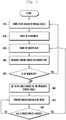
FIG. 4 illustrates a flow chart describing a first exemplary embodiment of a method for operating a mobile device according to an exemplary embodiment of the present invention. - Referring to
FIGS. 1 and4 , thesensor hub 120 stores state values of the mobile device 100, which are measured by thesensor unit 130 or received via theAP 110 instep 410. The state values received via theAP 110 may be a user's input values 110 or values transmitted from the other processors including a CP. Thesensor hub 120 may receive a user directly input values via theAP 110. Thesensor hub 120 may set sensor sampling periods based on the stored state values of the mobile device 100. - The
AP 110 enters sleep mode instep 420. Entering sleep mode is executed by one or more cases as follows: if the operations of the mobile device 100 are stopped according to a user's request; if a user's inputs are not created for a relatively long period of time; if a value measured via thesensor unit 130 and received by thesensor hub 120 is within a certain range; and/or if the reduction of power consumption is needed. If theAP 110 enters sleep mode, most operations are not executed in theAP 110, thereby reducing power consumption. During sleep mode, theAP 110 may operate only a module for receiving a wake-up signal in normal mode. When the module receives a wake-up signal, theAP 110 can reactivate the other modules that have been disabled in the sleep mode. If theAP 110 enters sleep mode, thesensor hub 120 may also enter sleep mode. - When the
sensor hub 120 is woken up instep 430, thesensor hub 120 controls thesensor unit 130 and receives the measured values from thesensor unit 130 instep 440. The values measured by thesensor unit 130 may be state information regarding the mobile device 100. - The
sensor hub 120 determines whether theAP 110 is woken up instep 450. TheAP 110 may be woken up via a wake-up signal from thesensor hub 120. Alternatively, theAP 110 may be woken up via a wake-up signal from the components of the mobile device 100, such as the CP. If thesensor hub 120 ascertains that theAP 110 has been woken up atstep 450, thesensor hub 120 returns to step 410 where thesensor hub 120 stores state values of the mobile device 100 and performs the following processes. - If the
sensor hub 120 ascertains that theAP 110 has not been woken up atstep 450, thesensor hub 120 sets a state value based on the measured values of thesensor unit 130, received atstep 440, instep 460. The state value may include a period in which thesensor hub 120 receives measured values from thesensor unit 130 during the sleep mode. The period in which thesensor hub 120 receives measured values is called a sensor sampling period. Since the sensor sampling period is set based on the measured values of thesensor unit 130, the sensor sampling period can be selectively adjusted and set according to the surrounding conditions of the mobile device 100. This can reduce electric power consumption in the mobile device 100 and also enhance the response of the mobile device 100. - The
sensor hub 120 sets a sensor sampling period according to the measured values of thesensor unit 130. If the user's inputs have not been created frequently in the mobile device 100, based on the number of measured values of thesensor unit 130, thesensor hub 120 may increase the length of a sensor sampling period. If the user's inputs have been created frequently in the mobile device 100, or the variation of the measured values of thesensor unit 130 has been large, thesensor hub 120 may decrease the length of a sensor sampling period. - The
sensor hub 120 enters sleep mode instep 470. Thesensor hub 120 determines whether the sensor sampling period, set atstep 460, has elapsed instep 480. If thesensor hub 120 ascertains that the sensor sampling period has elapsed atstep 480, the sensor hub 120returns to step 430 where thesensor hub 120 is woken up and receives measured values of thesensor unit 130. Otherwise, thesensor hub 120 continues to operate in sleep mode instep 470, thereby reducing power consumption. -
FIG. 5 illustrates a flow chart describing a second exemplary embodiment of a method for operating a mobile device according to an exemplary embodiment of the present invention. - Referring to
FIGS. 1 and5 , thesensor hub 120 sets a wake-up period according to the use states of the mobile device 100 instep 510. The use states are based on the user's inputs or measured values of thesensor unit 130. The wake-up period of thesensor hub 120 corresponds to a sampling period of thesensor unit 130, and is thus referred to as a sensor sampling period. If the mobile device is designed to support an alarm function and is set to operate the sleep wake-up function according to a user's input, thesensor hub 120 may set the sensor sampling period to be relatively large. For example, if a sensor sampling period has been set to 20 ms and a wake-up function has been set in the mobile device 100, thesensor hub 120 may set the sensor sampling period to 200 ms. Alternatively, the mobile device 100 may perform a sampling operation more frequently as a preset alarm time approaches. To this end, the sensor sampling period may be re-set to 20 ms. An example of the use state is an alarm time. - The
sensor hub 120 enters sleep mode and operates in the mode for the sensor sampling period set atstep 510 instep 520. During the sleep mode, thesensor hub 120 executes only an operation for determining whether the sampling period has elapsed, and this minimizes electric power consumption. - The
sensor hub 120 determines whether theAP 110 is woken up instep 530. This can be executed via a signal transmitted from theAP 110. TheAP 110 transmits a control signal to thesensor hub 120 and operates thesensor hub 120 in a wake-up state. - The
AP 110 may be woken up via a user's input signal or/and according to the operation of theCP.The AP 110 may be woken up via a wake-up signal from thesensor hub 120, during the sleep mode. Alternatively, theAP 110 may be woken up via a wake-up signal from the other components of the mobile device 100. For example, theAP 110 may be woken up via a wake-up signal from the CP that executes call-related operations in the mobile device 100. The CP may be enabled while theAP 110 operates in sleep mode. Accordingly, if the mobile device 100 receives a call request from an external system, the CP transfers a wake-up signal to theAP 110. - If the
AP 110 is woken up atstep 530, thesensor hub 120 re-sets a sensor sampling period based on the wake-up signal from theAP 110 or values that thesensor unit 130 has measured instep 570. When theAP 110 operates in normal mode, thesensor hub 120 receives measured values from thesensor unit 130, stores the measured values, and transfers the measured values to theAP 110. - If the
AP 110 is not woken up atstep 530, thesensor hub 120 operates in sleep mode until the set, sensor sampling period elapses instep 540. - If the set sensor sampling period has elapsed at
step 540, thesensor hub 120 operates in wake-up mode, controls thesensor unit 130, and receives the measured values from one or more sensors of thesensor unit 130 instep 550. - In addition, the
sensor hub 120 may re-set a sensor sampling period based on the measured values. If the variation of the measured values is less than or equal to a preset value, thesensor hub 120 may set a sensor sampling period to be relatively large. If the variation of the measured values is greater than or equal to another preset value, thesensor hub 120 may set a sensor sampling period to be relatively small. If the variation of the measured values is within a preset range, thesensor hub 120 may set a sensor sampling period to be the same as the previous sensor sampling period. - After setting a sensor sampling period at
step 550, thesensor hub 120 determines whether thesensor hub 120 needs to wake up theAP 110 based on the measured values received atstep 550 instep 560. If the measured values are within a preset range or the variation of the measured values is within a preset range, thesensor hub 120 wakes up theAP 110. - If the
sensor hub 120 needs to wake up theAP 110 atstep 560, thesensor hub 120 transfers a wake-up signal including the measured values to theAP 110. If theAP 110 is woken up, thesensor hub 120 re-sets a sensor sampling period based on the measured values atstep 570. - If the
sensor hub 120 does not need to wake up the AP atstep 560, thesensor hub 120 returns to step 520 where thesensor hub 120 operates in sleep mode for the set, sensor sampling period. - As described above, since the mobile device 100 includes the
sensor hub 120 for controlling sensors, the mobile device 100 can control the sensors via the sensor hub irrespective of the operations of the main processor. When the mobile device operates in sleep mode, only thesensor hub 120 is woken up and measures the states via the sensors. As a result, overhead may be reduced. In addition, thesensor hub 120 sets a sensor sampling period based on the received state value of the mobile device 100, e.g., sampling conditions and sampled results, thereby enhancing convenience of the mobile device, and preventing an increase in power consumption, and the decrease of response of the mobile device. - Certain aspects of the present invention can also be embodied as computer readable code on a computer readable recording medium. A computer readable recording medium is any data storage device that can store data which can be thereafter read by a computer system. Examples of the computer readable recording medium include Read-Only Memory (ROM), Random-Access Memory (RAM), CD-ROMs, magnetic tapes, floppy disks, and optical data storage devices. The computer readable recording medium can also be distributed over network coupled computer systems so that the computer readable code is stored and executed in a distributed fashion. Also, functional programs, code, and code segments for accomplishing the present invention can be easily construed by programmers skilled in the art to which the present invention pertains.
Claims (7)
- A method for controlling a mobile device (100) comprising a processor (110) for controlling the mobile device (100), a sensor hub (120) and a sensor unit (130) comprising one or more sensors (210-290) for measuring a parameter, the method comprising:receiving (410, 510), by the sensor hub (120), state information regarding the mobile device, the state information comprising a parameter value measured by one or more sensors;setting (410, 510), by the sensor hub (120), a sensor hub wake up period based on the received state information; andwhile the sensor hub (120) is in wake up mode based on the set sensor hub wake up period and while the processor (110) is in a sleep mode in which the processor is operable only to receive a wake-up signal from the sensor hub (120):receiving (440, 550), by the sensor hub (120), measured values from one or more sensors (210-290); andre-setting (460, 550), by the sensor hub (120), the sensor hub wake up period based on the measured values.
- The method of claim 1, wherein the reception (440, 550) of measured values comprises:
operating the sensor hub (120) in sleep mode for the sensor hub wake up period, and receiving (440, 550) the measured values from one or more sensors (210-290) after the sensor hub wake up period has elapsed. - The method of claim 1, further comprising:
transferring (450, 560), by the sensor hub (120), a wake-up signal to the processor if one or more of the measured values are within a preset range; and:
transferring, by the sensor hub (120), information regarding the measured values to the processor (110). - A mobile device (100) comprising:a processor (110) arranged to control the mobile device (100);a sensor unit (130) comprising one or more sensors (210-290) arranged to measure a parameter; anda sensor hub (120) arranged:to control the one or more sensors (210-290);to receive (410, 510) state information regarding the mobile device, the state information comprising a parameter value measured by one or more sensors; andto set (410, 510) a sensor hub wake up period based on the received state information;wherein while the sensor hub (120) is in wake up mode based on the set sensor hub wake up period and while the processor (110) is in a sleep mode in which the processor is operable only to receive a wake-up signal from the sensor hub (120) the sensor hub (120) further arranged:to receive (440, 550) measured values from one or more sensors (210-290); and
re-set (460, 550) the sensor hub wake up period based on the measured values. - The mobile device (100) of claim 4, wherein the sensor hub (120) is further arranged to operate the sensor hub (120) in sleep mode for the sensor hub wake up period, and to receive (440, 550) the measured values from the one or more sensors (210-290) after the sensor hub wake up period has elapsed.
- The mobile device of claim 4, wherein the sensor hub (120) is further arranged:to transfer a wake-up signal to the processor (110) based on one or more of the measured values; andto transfer one or more of the measured values to the processor (110).
- The mobile device (100) of claim 4, wherein if a certain period of time has elapsed after setting the sensor hub wake up period, the sensor hub (120) is further arranged to alter the length of the sensor hub wake up period, based on the state information received from the processor (110).
Applications Claiming Priority (1)
| Application Number | Priority Date | Filing Date | Title |
|---|---|---|---|
| KR1020120078303A KR102045511B1 (en) | 2012-07-18 | 2012-07-18 | Terminal including sensor hub and method for controlling terminal thereof |
Publications (3)
| Publication Number | Publication Date |
|---|---|
| EP2687945A2 EP2687945A2 (en) | 2014-01-22 |
| EP2687945A3 EP2687945A3 (en) | 2014-07-02 |
| EP2687945B1 true EP2687945B1 (en) | 2018-10-31 |
Family
ID=48832767
Family Applications (1)
| Application Number | Title | Priority Date | Filing Date |
|---|---|---|---|
| EP13176821.0A Active EP2687945B1 (en) | 2012-07-18 | 2013-07-17 | Mobile device with sensor hub and method for controlling the device |
Country Status (4)
| Country | Link |
|---|---|
| US (2) | US20140025975A1 (en) |
| EP (1) | EP2687945B1 (en) |
| KR (1) | KR102045511B1 (en) |
| CN (2) | CN110096135B (en) |
Families Citing this family (19)
| Publication number | Priority date | Publication date | Assignee | Title |
|---|---|---|---|---|
| US8638230B2 (en) | 2012-05-24 | 2014-01-28 | Google Inc. | Hardware attitude detection implementation of mobile devices with MEMS motion sensors |
| US20140351560A1 (en) * | 2013-05-24 | 2014-11-27 | Motorola Mobility Llc | Low Power Management of Multiple Sensor Integrated Chip Architecture |
| US10079019B2 (en) | 2013-11-12 | 2018-09-18 | Apple Inc. | Always-on audio control for mobile device |
| US9778728B2 (en) | 2014-05-29 | 2017-10-03 | Apple Inc. | System on a chip with fast wake from sleep |
| US9619377B2 (en) * | 2014-05-29 | 2017-04-11 | Apple Inc. | System on a chip with always-on processor which reconfigures SOC and supports memory-only communication mode |
| US10031000B2 (en) * | 2014-05-29 | 2018-07-24 | Apple Inc. | System on a chip with always-on processor |
| US20160094945A1 (en) * | 2014-09-26 | 2016-03-31 | Sunil Kulkarni | Variable interval for periodic fix requests of multiple clients |
| WO2016093579A1 (en) * | 2014-12-09 | 2016-06-16 | Samsung Electronics Co., Ltd. | Method and apparatus for controlling multiple processors to reduce current consumption |
| US20160202997A1 (en) * | 2015-01-09 | 2016-07-14 | Sheng-Chia Optical Co., Ltd. | Portable device operating system |
| CN104978303B (en) * | 2015-06-19 | 2019-06-04 | 上海兆芯集成电路有限公司 | Single-chip integrated sensor hub and multi-sensor management method |
| US11019149B2 (en) | 2015-07-10 | 2021-05-25 | Samsung Electronics Co., Ltd | Hub apparatus and method for providing service thereof |
| KR102569400B1 (en) * | 2015-07-10 | 2023-08-24 | 삼성전자주식회사 | Hub apparatus and Method for providing service thereof |
| CN105183136A (en) * | 2015-09-07 | 2015-12-23 | 联想(北京)有限公司 | Electronic equipment and information processing method |
| US10716068B2 (en) * | 2017-10-13 | 2020-07-14 | Denso International America, Inc. | Power saving methods for communication in localization systems |
| KR102568686B1 (en) * | 2018-02-09 | 2023-08-23 | 삼성전자주식회사 | Mobile device including context hub and operation method thereof |
| CN108833695B (en) * | 2018-06-06 | 2020-07-31 | Oppo广东移动通信有限公司 | Control method, control device, electronic device, computer storage medium and equipment |
| WO2020066018A1 (en) * | 2018-09-28 | 2020-04-02 | 三菱電機株式会社 | Air conditioning system and application program |
| KR20220109944A (en) * | 2021-01-29 | 2022-08-05 | 삼성전자주식회사 | Electronic device for synchronizing time of received data records and method thereof |
| CN118093458A (en) | 2024-03-07 | 2024-05-28 | 合肥沛睿微电子股份有限公司 | Hub and polling method for two-wire serial bus |
Family Cites Families (30)
| Publication number | Priority date | Publication date | Assignee | Title |
|---|---|---|---|---|
| US20030122810A1 (en) * | 2001-12-31 | 2003-07-03 | Tsirkel Aaron M. | Method and apparatus to adjust the brightness of a display screen |
| US6878121B2 (en) * | 2002-11-01 | 2005-04-12 | David T. Krausman | Sleep scoring apparatus and method |
| JP4173495B2 (en) * | 2005-05-27 | 2008-10-29 | 京セラミタ株式会社 | Electronic equipment and monitoring program |
| US7701434B2 (en) * | 2005-10-31 | 2010-04-20 | Research In Motion Limited | Automatic screen and keypad brightness adjustment on a mobile handheld electronic device |
| KR100827150B1 (en) * | 2006-07-10 | 2008-05-02 | 삼성전자주식회사 | Apparatus for driving in portable terminal having a touch pad |
| KR20080006987A (en) | 2006-07-14 | 2008-01-17 | 엘지전자 주식회사 | Plasma display device |
| HUE047118T2 (en) * | 2007-03-23 | 2020-04-28 | Qualcomm Inc | Multi-sensor data collection and/or processing |
| CN101458557B (en) * | 2007-12-14 | 2010-12-15 | 宏达国际电子股份有限公司 | power supply management method of handheld electronic device |
| CN102027379B (en) * | 2008-05-13 | 2013-01-02 | 皇家飞利浦电子股份有限公司 | Fall Detection System |
| US8823518B2 (en) * | 2008-12-08 | 2014-09-02 | Motorola Solutions, Inc. | Method of sensor cluster processing for a communication device |
| CN101866210B (en) | 2009-04-16 | 2012-03-21 | 群康科技(深圳)有限公司 | Power saving device and method for capacitive touch pad and capacitive touch pad |
| US8405505B2 (en) * | 2009-05-26 | 2013-03-26 | Qualcomm Incorporated | Power management of sensors within a mobile device |
| US9086875B2 (en) * | 2009-06-05 | 2015-07-21 | Qualcomm Incorporated | Controlling power consumption of a mobile device based on gesture recognition |
| US7873849B2 (en) * | 2009-09-02 | 2011-01-18 | Apple Inc. | Motion sensor data processing using various power management modes |
| KR20110031797A (en) * | 2009-09-21 | 2011-03-29 | 삼성전자주식회사 | Input device and method of mobile terminal |
| US8780055B2 (en) * | 2009-10-02 | 2014-07-15 | Blackberry Limited | Low power wakeup detection circuit and a portable electronic device having a low power wakeup detection circuit |
| US8508465B2 (en) * | 2009-11-05 | 2013-08-13 | Research In Motion Limited | Multiple orientation mobile electronic handheld device and method of ambient light sensing and backlight adjustment implemented therein |
| US9383867B2 (en) | 2009-11-09 | 2016-07-05 | Rohm Co., Ltd. | Touch display having proximity sensor electrode pair with each electrode formed on the top face of the display panel so as to overlap the display region |
| US20110215903A1 (en) * | 2010-03-04 | 2011-09-08 | Nokia Corporation | Apparatus and Associated Methods |
| WO2011112192A1 (en) * | 2010-03-11 | 2011-09-15 | Thomson Licensing | Apparatus and method for conserving power for devices |
| KR101647039B1 (en) * | 2010-06-04 | 2016-08-09 | 삼성전자 주식회사 | Method and apparatus for performing pedometer function for decreasing current consumption in mobile terminal |
| US9317082B2 (en) * | 2010-10-13 | 2016-04-19 | Advanced Micro Devices, Inc. | Controlling operation of temperature sensors |
| US8706172B2 (en) * | 2010-10-26 | 2014-04-22 | Miscrosoft Corporation | Energy efficient continuous sensing for communications devices |
| US20120218282A1 (en) * | 2011-02-25 | 2012-08-30 | Research In Motion Limited | Display Brightness Adjustment |
| US20120254878A1 (en) * | 2011-04-01 | 2012-10-04 | Lama Nachman | Mechanism for outsourcing context-aware application-related functionalities to a sensor hub |
| US9229489B2 (en) * | 2011-05-03 | 2016-01-05 | Facebook, Inc. | Adjusting mobile device state based on user intentions and/or identity |
| CN202206549U (en) * | 2011-06-03 | 2012-04-25 | 上海申腾信息技术有限公司 | A wireless sensor network energy consumption control system |
| US8918665B2 (en) * | 2011-09-23 | 2014-12-23 | Wing Kong Low | Operating input device in low power mode with auxiliary sensor calibrated to main sensor |
| KR102179811B1 (en) * | 2012-12-03 | 2020-11-17 | 엘지전자 주식회사 | Portable Device And Method For Providing Voice Recognition Service |
| WO2015099802A1 (en) * | 2013-12-28 | 2015-07-02 | Intel Corporation | Techniques for increasing energy efficiency of sensor controllers |
-
2012
- 2012-07-18 KR KR1020120078303A patent/KR102045511B1/en active Active
-
2013
- 2013-07-12 US US13/940,919 patent/US20140025975A1/en not_active Abandoned
- 2013-07-16 CN CN201811587450.XA patent/CN110096135B/en active Active
- 2013-07-16 CN CN201310297048.9A patent/CN103576852B/en active Active
- 2013-07-17 EP EP13176821.0A patent/EP2687945B1/en active Active
-
2018
- 2018-04-27 US US15/964,964 patent/US11194376B2/en active Active
Non-Patent Citations (1)
| Title |
|---|
| None * |
Also Published As
| Publication number | Publication date |
|---|---|
| CN103576852A (en) | 2014-02-12 |
| EP2687945A2 (en) | 2014-01-22 |
| US20140025975A1 (en) | 2014-01-23 |
| US20180246559A1 (en) | 2018-08-30 |
| KR20140011660A (en) | 2014-01-29 |
| CN110096135A (en) | 2019-08-06 |
| US11194376B2 (en) | 2021-12-07 |
| KR102045511B1 (en) | 2019-11-15 |
| EP2687945A3 (en) | 2014-07-02 |
| CN103576852B (en) | 2019-01-18 |
| CN110096135B (en) | 2022-08-05 |
Similar Documents
| Publication | Publication Date | Title |
|---|---|---|
| US11194376B2 (en) | Mobile device with sensor hub and method for controlling the device | |
| KR102562458B1 (en) | Dormancy controlling method for on board computing platform, device and readable storage medium | |
| US11009933B2 (en) | Apparatus and method for waking up a processor | |
| US20240241565A1 (en) | Mobile device including context hub and operation method thereof | |
| EP2649844B1 (en) | Processing involving multiple sensors | |
| CN101610300B (en) | Method and device for controlling backlight of mobile terminal | |
| EP3623776A2 (en) | Dynamic power consumption management and wake-up method and application system therefor | |
| US8456136B2 (en) | Method and apparatus for battery gauging in portable terminal | |
| RU2010145919A (en) | POWER MANAGEMENT USING AT LEAST, ONE OF THE SPECIALIZED PROCESSOR AND PERCEPTION OF MOTION | |
| CN107357411B (en) | electronic device | |
| CN110572868B (en) | Method and device for reducing power consumption of electronic device | |
| US20150237579A1 (en) | Control methods and apparatuses of mobile terminals | |
| CN107317924B (en) | Mobile terminal and sleep method of mobile terminal | |
| EP2835717A2 (en) | User device and method to process sensor output using a plurality of processors | |
| TWI493334B (en) | Method for reducing power consumption and sensor management system for performing the same | |
| JP2022048146A5 (en) | ||
| CN109739339B (en) | Control method and device | |
| CN112596600B (en) | Screen unlocking method and device, storage medium and mobile terminal | |
| CN112542867B (en) | Mobile terminal power supply control method, device, terminal equipment and storage medium | |
| US11107379B2 (en) | Information processing apparatus and information processing method | |
| KR102902552B1 (en) | An electronic device and a method controlling the same | |
| CN104700815A (en) | Brightness control device and brightness control method | |
| CN113079249B (en) | Prompting method, prompting device, storage medium and mobile terminal | |
| CN109445566B (en) | OTG (on-the-go) power-saving processing method and system, storage medium and mobile terminal |
Legal Events
| Date | Code | Title | Description |
|---|---|---|---|
| PUAI | Public reference made under article 153(3) epc to a published international application that has entered the european phase |
Free format text: ORIGINAL CODE: 0009012 |
|
| AK | Designated contracting states |
Kind code of ref document: A2 Designated state(s): AL AT BE BG CH CY CZ DE DK EE ES FI FR GB GR HR HU IE IS IT LI LT LU LV MC MK MT NL NO PL PT RO RS SE SI SK SM TR |
|
| AX | Request for extension of the european patent |
Extension state: BA ME |
|
| PUAL | Search report despatched |
Free format text: ORIGINAL CODE: 0009013 |
|
| AK | Designated contracting states |
Kind code of ref document: A3 Designated state(s): AL AT BE BG CH CY CZ DE DK EE ES FI FR GB GR HR HU IE IS IT LI LT LU LV MC MK MT NL NO PL PT RO RS SE SI SK SM TR |
|
| AX | Request for extension of the european patent |
Extension state: BA ME |
|
| RIC1 | Information provided on ipc code assigned before grant |
Ipc: G06F 1/32 20060101AFI20140528BHEP Ipc: H04W 52/02 20090101ALI20140528BHEP |
|
| 17P | Request for examination filed |
Effective date: 20141223 |
|
| STAA | Information on the status of an ep patent application or granted ep patent |
Free format text: STATUS: EXAMINATION IS IN PROGRESS |
|
| 17Q | First examination report despatched |
Effective date: 20161205 |
|
| GRAP | Despatch of communication of intention to grant a patent |
Free format text: ORIGINAL CODE: EPIDOSNIGR1 |
|
| STAA | Information on the status of an ep patent application or granted ep patent |
Free format text: STATUS: GRANT OF PATENT IS INTENDED |
|
| INTG | Intention to grant announced |
Effective date: 20180816 |
|
| GRAS | Grant fee paid |
Free format text: ORIGINAL CODE: EPIDOSNIGR3 |
|
| GRAA | (expected) grant |
Free format text: ORIGINAL CODE: 0009210 |
|
| STAA | Information on the status of an ep patent application or granted ep patent |
Free format text: STATUS: THE PATENT HAS BEEN GRANTED |
|
| AK | Designated contracting states |
Kind code of ref document: B1 Designated state(s): AL AT BE BG CH CY CZ DE DK EE ES FI FR GB GR HR HU IE IS IT LI LT LU LV MC MK MT NL NO PL PT RO RS SE SI SK SM TR |
|
| REG | Reference to a national code |
Ref country code: CH Ref legal event code: EP Ref country code: GB Ref legal event code: FG4D |
|
| REG | Reference to a national code |
Ref country code: AT Ref legal event code: REF Ref document number: 1060167 Country of ref document: AT Kind code of ref document: T Effective date: 20181115 |
|
| REG | Reference to a national code |
Ref country code: IE Ref legal event code: FG4D |
|
| REG | Reference to a national code |
Ref country code: DE Ref legal event code: R096 Ref document number: 602013045839 Country of ref document: DE |
|
| REG | Reference to a national code |
Ref country code: NL Ref legal event code: FP |
|
| REG | Reference to a national code |
Ref country code: LT Ref legal event code: MG4D |
|
| REG | Reference to a national code |
Ref country code: AT Ref legal event code: MK05 Ref document number: 1060167 Country of ref document: AT Kind code of ref document: T Effective date: 20181031 |
|
| PG25 | Lapsed in a contracting state [announced via postgrant information from national office to epo] |
Ref country code: FI Free format text: LAPSE BECAUSE OF FAILURE TO SUBMIT A TRANSLATION OF THE DESCRIPTION OR TO PAY THE FEE WITHIN THE PRESCRIBED TIME-LIMIT Effective date: 20181031 Ref country code: IS Free format text: LAPSE BECAUSE OF FAILURE TO SUBMIT A TRANSLATION OF THE DESCRIPTION OR TO PAY THE FEE WITHIN THE PRESCRIBED TIME-LIMIT Effective date: 20190228 Ref country code: AT Free format text: LAPSE BECAUSE OF FAILURE TO SUBMIT A TRANSLATION OF THE DESCRIPTION OR TO PAY THE FEE WITHIN THE PRESCRIBED TIME-LIMIT Effective date: 20181031 Ref country code: HR Free format text: LAPSE BECAUSE OF FAILURE TO SUBMIT A TRANSLATION OF THE DESCRIPTION OR TO PAY THE FEE WITHIN THE PRESCRIBED TIME-LIMIT Effective date: 20181031 Ref country code: NO Free format text: LAPSE BECAUSE OF FAILURE TO SUBMIT A TRANSLATION OF THE DESCRIPTION OR TO PAY THE FEE WITHIN THE PRESCRIBED TIME-LIMIT Effective date: 20190131 Ref country code: LV Free format text: LAPSE BECAUSE OF FAILURE TO SUBMIT A TRANSLATION OF THE DESCRIPTION OR TO PAY THE FEE WITHIN THE PRESCRIBED TIME-LIMIT Effective date: 20181031 Ref country code: ES Free format text: LAPSE BECAUSE OF FAILURE TO SUBMIT A TRANSLATION OF THE DESCRIPTION OR TO PAY THE FEE WITHIN THE PRESCRIBED TIME-LIMIT Effective date: 20181031 Ref country code: LT Free format text: LAPSE BECAUSE OF FAILURE TO SUBMIT A TRANSLATION OF THE DESCRIPTION OR TO PAY THE FEE WITHIN THE PRESCRIBED TIME-LIMIT Effective date: 20181031 Ref country code: PL Free format text: LAPSE BECAUSE OF FAILURE TO SUBMIT A TRANSLATION OF THE DESCRIPTION OR TO PAY THE FEE WITHIN THE PRESCRIBED TIME-LIMIT Effective date: 20181031 Ref country code: BG Free format text: LAPSE BECAUSE OF FAILURE TO SUBMIT A TRANSLATION OF THE DESCRIPTION OR TO PAY THE FEE WITHIN THE PRESCRIBED TIME-LIMIT Effective date: 20190131 |
|
| PG25 | Lapsed in a contracting state [announced via postgrant information from national office to epo] |
Ref country code: AL Free format text: LAPSE BECAUSE OF FAILURE TO SUBMIT A TRANSLATION OF THE DESCRIPTION OR TO PAY THE FEE WITHIN THE PRESCRIBED TIME-LIMIT Effective date: 20181031 Ref country code: PT Free format text: LAPSE BECAUSE OF FAILURE TO SUBMIT A TRANSLATION OF THE DESCRIPTION OR TO PAY THE FEE WITHIN THE PRESCRIBED TIME-LIMIT Effective date: 20190301 Ref country code: SE Free format text: LAPSE BECAUSE OF FAILURE TO SUBMIT A TRANSLATION OF THE DESCRIPTION OR TO PAY THE FEE WITHIN THE PRESCRIBED TIME-LIMIT Effective date: 20181031 Ref country code: GR Free format text: LAPSE BECAUSE OF FAILURE TO SUBMIT A TRANSLATION OF THE DESCRIPTION OR TO PAY THE FEE WITHIN THE PRESCRIBED TIME-LIMIT Effective date: 20190201 Ref country code: RS Free format text: LAPSE BECAUSE OF FAILURE TO SUBMIT A TRANSLATION OF THE DESCRIPTION OR TO PAY THE FEE WITHIN THE PRESCRIBED TIME-LIMIT Effective date: 20181031 |
|
| PG25 | Lapsed in a contracting state [announced via postgrant information from national office to epo] |
Ref country code: CZ Free format text: LAPSE BECAUSE OF FAILURE TO SUBMIT A TRANSLATION OF THE DESCRIPTION OR TO PAY THE FEE WITHIN THE PRESCRIBED TIME-LIMIT Effective date: 20181031 Ref country code: IT Free format text: LAPSE BECAUSE OF FAILURE TO SUBMIT A TRANSLATION OF THE DESCRIPTION OR TO PAY THE FEE WITHIN THE PRESCRIBED TIME-LIMIT Effective date: 20181031 Ref country code: DK Free format text: LAPSE BECAUSE OF FAILURE TO SUBMIT A TRANSLATION OF THE DESCRIPTION OR TO PAY THE FEE WITHIN THE PRESCRIBED TIME-LIMIT Effective date: 20181031 |
|
| REG | Reference to a national code |
Ref country code: DE Ref legal event code: R097 Ref document number: 602013045839 Country of ref document: DE |
|
| PG25 | Lapsed in a contracting state [announced via postgrant information from national office to epo] |
Ref country code: EE Free format text: LAPSE BECAUSE OF FAILURE TO SUBMIT A TRANSLATION OF THE DESCRIPTION OR TO PAY THE FEE WITHIN THE PRESCRIBED TIME-LIMIT Effective date: 20181031 Ref country code: SM Free format text: LAPSE BECAUSE OF FAILURE TO SUBMIT A TRANSLATION OF THE DESCRIPTION OR TO PAY THE FEE WITHIN THE PRESCRIBED TIME-LIMIT Effective date: 20181031 Ref country code: RO Free format text: LAPSE BECAUSE OF FAILURE TO SUBMIT A TRANSLATION OF THE DESCRIPTION OR TO PAY THE FEE WITHIN THE PRESCRIBED TIME-LIMIT Effective date: 20181031 Ref country code: SK Free format text: LAPSE BECAUSE OF FAILURE TO SUBMIT A TRANSLATION OF THE DESCRIPTION OR TO PAY THE FEE WITHIN THE PRESCRIBED TIME-LIMIT Effective date: 20181031 |
|
| PLBE | No opposition filed within time limit |
Free format text: ORIGINAL CODE: 0009261 |
|
| STAA | Information on the status of an ep patent application or granted ep patent |
Free format text: STATUS: NO OPPOSITION FILED WITHIN TIME LIMIT |
|
| 26N | No opposition filed |
Effective date: 20190801 |
|
| PG25 | Lapsed in a contracting state [announced via postgrant information from national office to epo] |
Ref country code: SI Free format text: LAPSE BECAUSE OF FAILURE TO SUBMIT A TRANSLATION OF THE DESCRIPTION OR TO PAY THE FEE WITHIN THE PRESCRIBED TIME-LIMIT Effective date: 20181031 |
|
| PG25 | Lapsed in a contracting state [announced via postgrant information from national office to epo] |
Ref country code: MC Free format text: LAPSE BECAUSE OF FAILURE TO SUBMIT A TRANSLATION OF THE DESCRIPTION OR TO PAY THE FEE WITHIN THE PRESCRIBED TIME-LIMIT Effective date: 20181031 |
|
| REG | Reference to a national code |
Ref country code: CH Ref legal event code: PL |
|
| PG25 | Lapsed in a contracting state [announced via postgrant information from national office to epo] |
Ref country code: TR Free format text: LAPSE BECAUSE OF FAILURE TO SUBMIT A TRANSLATION OF THE DESCRIPTION OR TO PAY THE FEE WITHIN THE PRESCRIBED TIME-LIMIT Effective date: 20181031 |
|
| REG | Reference to a national code |
Ref country code: BE Ref legal event code: MM Effective date: 20190731 |
|
| PG25 | Lapsed in a contracting state [announced via postgrant information from national office to epo] |
Ref country code: LU Free format text: LAPSE BECAUSE OF NON-PAYMENT OF DUE FEES Effective date: 20190717 Ref country code: CH Free format text: LAPSE BECAUSE OF NON-PAYMENT OF DUE FEES Effective date: 20190731 Ref country code: LI Free format text: LAPSE BECAUSE OF NON-PAYMENT OF DUE FEES Effective date: 20190731 Ref country code: BE Free format text: LAPSE BECAUSE OF NON-PAYMENT OF DUE FEES Effective date: 20190731 |
|
| PG25 | Lapsed in a contracting state [announced via postgrant information from national office to epo] |
Ref country code: FR Free format text: LAPSE BECAUSE OF NON-PAYMENT OF DUE FEES Effective date: 20190731 |
|
| PG25 | Lapsed in a contracting state [announced via postgrant information from national office to epo] |
Ref country code: IE Free format text: LAPSE BECAUSE OF NON-PAYMENT OF DUE FEES Effective date: 20190717 |
|
| PG25 | Lapsed in a contracting state [announced via postgrant information from national office to epo] |
Ref country code: CY Free format text: LAPSE BECAUSE OF FAILURE TO SUBMIT A TRANSLATION OF THE DESCRIPTION OR TO PAY THE FEE WITHIN THE PRESCRIBED TIME-LIMIT Effective date: 20181031 |
|
| PG25 | Lapsed in a contracting state [announced via postgrant information from national office to epo] |
Ref country code: MT Free format text: LAPSE BECAUSE OF FAILURE TO SUBMIT A TRANSLATION OF THE DESCRIPTION OR TO PAY THE FEE WITHIN THE PRESCRIBED TIME-LIMIT Effective date: 20181031 Ref country code: HU Free format text: LAPSE BECAUSE OF FAILURE TO SUBMIT A TRANSLATION OF THE DESCRIPTION OR TO PAY THE FEE WITHIN THE PRESCRIBED TIME-LIMIT; INVALID AB INITIO Effective date: 20130717 |
|
| PG25 | Lapsed in a contracting state [announced via postgrant information from national office to epo] |
Ref country code: MK Free format text: LAPSE BECAUSE OF FAILURE TO SUBMIT A TRANSLATION OF THE DESCRIPTION OR TO PAY THE FEE WITHIN THE PRESCRIBED TIME-LIMIT Effective date: 20181031 |
|
| PGFP | Annual fee paid to national office [announced via postgrant information from national office to epo] |
Ref country code: GB Payment date: 20250624 Year of fee payment: 13 |
|
| PGFP | Annual fee paid to national office [announced via postgrant information from national office to epo] |
Ref country code: NL Payment date: 20250623 Year of fee payment: 13 |
|
| PGFP | Annual fee paid to national office [announced via postgrant information from national office to epo] |
Ref country code: DE Payment date: 20250624 Year of fee payment: 13 |