EP2687926A2 - Contexte de collaboration commune entre un opérateur de console et un opérateur de champ - Google Patents
Contexte de collaboration commune entre un opérateur de console et un opérateur de champ Download PDFInfo
- Publication number
- EP2687926A2 EP2687926A2 EP13174789.1A EP13174789A EP2687926A2 EP 2687926 A2 EP2687926 A2 EP 2687926A2 EP 13174789 A EP13174789 A EP 13174789A EP 2687926 A2 EP2687926 A2 EP 2687926A2
- Authority
- EP
- European Patent Office
- Prior art keywords
- operator
- equipment
- field
- current location
- physical
- Prior art date
- Legal status (The legal status is an assumption and is not a legal conclusion. Google has not performed a legal analysis and makes no representation as to the accuracy of the status listed.)
- Ceased
Links
Images


Classifications
-
- G—PHYSICS
- G05—CONTROLLING; REGULATING
- G05B—CONTROL OR REGULATING SYSTEMS IN GENERAL; FUNCTIONAL ELEMENTS OF SUCH SYSTEMS; MONITORING OR TESTING ARRANGEMENTS FOR SUCH SYSTEMS OR ELEMENTS
- G05B19/00—Programme-control systems
- G05B19/02—Programme-control systems electric
- G05B19/04—Programme control other than numerical control, i.e. in sequence controllers or logic controllers
- G05B19/042—Programme control other than numerical control, i.e. in sequence controllers or logic controllers using digital processors
- G05B19/0423—Input/output
- G05B19/0425—Safety, monitoring
-
- G—PHYSICS
- G06—COMPUTING; CALCULATING OR COUNTING
- G06N—COMPUTING ARRANGEMENTS BASED ON SPECIFIC COMPUTATIONAL MODELS
- G06N5/00—Computing arrangements using knowledge-based models
- G06N5/02—Knowledge representation; Symbolic representation
-
- G—PHYSICS
- G06—COMPUTING; CALCULATING OR COUNTING
- G06Q—INFORMATION AND COMMUNICATION TECHNOLOGY [ICT] SPECIALLY ADAPTED FOR ADMINISTRATIVE, COMMERCIAL, FINANCIAL, MANAGERIAL OR SUPERVISORY PURPOSES; SYSTEMS OR METHODS SPECIALLY ADAPTED FOR ADMINISTRATIVE, COMMERCIAL, FINANCIAL, MANAGERIAL OR SUPERVISORY PURPOSES, NOT OTHERWISE PROVIDED FOR
- G06Q10/00—Administration; Management
- G06Q10/06—Resources, workflows, human or project management; Enterprise or organisation planning; Enterprise or organisation modelling
Definitions
- Disclosed embodiments relate to the field of process control for controlling physical systems, such as industrial plants, which run physical processes involving tangible materials..
- Physical systems involve at least the transport of a tangible (i.e. real) product, while physical processes further involve the manufacture of a tangible product from one or more materials.
- the physical system may be a large geographically dispersed system (e.g., a gas pipeline) or complex multi-step process (e.g., for a large oil refinery). Physical systems may be contrasted with virtual systems which lack association with movement or processing of any tangible (i.e. real) materials.
- the physical system may comprise a process automation system which refers to a monitoring and control system, running a set of industrial processes that generate a physical (tangible) product, in which a distributed control system (DCS) may utilize controller elements to monitor and control the industrial processes.
- a distributed control system may utilize controller elements to monitor and control the industrial processes.
- Field operators are within the plant around the equipment (sometimes referred to as "assets") within the system.
- sensors for the industrial processes generate process data (e.g., temperatures, pressures) that is transmitted to the DCS, often in real time.
- the DCS subsequently displays the process data for human operators generally referred to as "console operators” which monitor and control the industrial process via graphical user interfaces (GUIs) displayed in a console of a control room.
- GUIs graphical user interfaces
- the components of the process automation system may be connected by a process control communications network.
- console operators working in a control room and field operators out within the system/plant.
- a challenge faced by console operators is that they generally support a plurality of field operators, and are tasked with collaborating with each of them as necessary.
- a field operator calling a console operator to request help with a task in the field, such as providing the field operator with directions or additional information (e.g., directing an operator to the correct valve to open).
- the console operator has to call up information relevant to the particular part of the system in which the field operator is currently located.
- This collaboration process generally involves the console operator manually and serially selecting and displaying the needed information, then reviewing the information including process schematics, alarm summaries, maintenance data, and information from a variety of sources (e.g., process data, such as sensor data) to enable providing the field operator with directions or additional information relevant to the task at hand.
- process data such as sensor data
- Disclosed embodiments include methods of operating a physical system that runs a physical process (e.g., an industrial plant) involving a console operator and a plurality of field operators which overcome the time consuming overhead of establishing a collaboration between the console operator and field operators as described above. Responsive to a field operator's wireless message (e.g., a call or text), configuration information for the equipment and process event data obtained from or relating to the equipment relevant to the field operator's current location in the system is efficiently selectively accessed (i.e. read) and then displayed for the console operator, such as process schematics, alarm summaries, maintenance data.
- a field operator's wireless message e.g., a call or text
- configuration information for the equipment and process event data obtained from or relating to the equipment relevant to the field operator's current location in the system is efficiently selectively accessed (i.e. read) and then displayed for the console operator, such as process schematics, alarm summaries, maintenance data.
- the console operator can invoke a disclosed algorithm that uses the field operator's location to rapidly display information relevant to equipment proximate to the current location.
- Disclosed methods thus allow significantly reducing the time taken to enter into a meaningful collaboration between a field operator and a console operator, and to establish situational awareness in an area of the system occupied by a particular field operator.
- the distance to define which equipment is "proximate” equipment can be set by engineering or management of the system or plant.
- the proximate equipment may be an entire process unit, in which case working out which equipment is proximate to the field operator's current location is fairly straightforward and can be based simply on the nearest equipment.
- the configuration information for the equipment and process event data is then automatically presented or is automatically made available by the appearance of a menu within a display screen viewable by the console operator. Automatic menu presentation has the advantage of awaiting an action on the part of the console operator to call up the information related to field operator's location, because the console operator may be concentrating on another matter when the field operator's call comes in and may not be able to switch his or her context immediately.
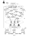
- FIG. 1 is a flow chart that shows steps in a method of operating a physical plant that runs a physical process involving collaboration between a console operator and a field operator, where the collaboration is enhanced by selected system data presented to the console operator based on the current location of the field operator, according to an example embodiment.
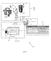
- FIG. 2 is a block diagram depiction of an example handheld computing device having a global positioning system (GPS) that provides location information of field operators, according to an example embodiment.
- GPS global positioning system
- FIG. 3 is a block diagram of a physical system comprising processing units, along with a wireless communications network including a network server, at least one router, and a plurality of field operators having handheld computing devices that provides their location information, according to an example embodiment.
- FIG. 4 simplified depiction that shows a field operator within a plant floor of an industrial plant having a handheld computing device that provides their current location information that is used to select information to display to a console operator viewing a console display in a control room of the industrial plant.
- FIG. 1 is a flow chart that shows steps in an example method 100 of operating a physical system (e.g., industrial plant) that runs a physical process involving collaboration between a console operator and a field operator, where the collaboration is enhanced by selected system data presented to the console operator based on the current location of the field operator, according to an example embodiment.
- Step 101 comprises the field operator sending a wireless message that reaches the console operator.
- the wireless message can directly reach the console operator, or reach the console operator after receipt by a network server having a wireless receiver.
- the wireless message includes a current location of the field operator.
- the wireless message can comprise a phone call or a text, for example.
- the field operator can be provided a handheld computing device having a wireless transceiver and a processor programmed to implement a location-based service algorithm stored in a memory comprising non-transitory machine readable storage, such as static random access memory (SRAM).
- the handheld computing device can be based on the DOLPHIN 9900 mobile computer provided by Honeywell International.
- the location-based service algorithm wirelessly obtains location information that identifies a current location of the field operator, and can add the location information to wireless transmissions of information from the field operator to the console operator or others in the system, or to the network server serving the system.
- the handheld computing device can include a global positioning system (GPS).
- GPS global positioning system
- a GPS is a space-based satellite navigation system that provides location and time information where there is an unobstructed line of sight to four (4) or more GPS satellites.
- the handheld computing device can calculate the current location of the field operator from timing information including timing information obtained from the network server, such as based on Timing Measurement Action (TMA) frames (e.g., as disclosed in the IEEE 802.11v specification).
- TMA Timing Measurement Action
- Wi-Fi may use a known mechanism to calculate location that is not based on timing information.
- the handheld computing device includes a camera and software for reading the bar code image data sensed by the camera.
- the bar code can provide location information.
- another source of location information useful for the worker can be provided by radio-frequency identification (RFID) tags when the equipment includes RFID tags.
- the handheld device includes RFID reader software.
- Step 102 comprises responsive to receiving the wireless message, reading selected information from a system database including both configuration information for the equipment and process event data obtained from or relating to the equipment.
- the configuration information for the equipment and process event data can be automatically displayed or be automatically made available by a menu within a display screen viewable by the console operator.
- menu presentation has the advantage of awaiting an action on the part of the console operator to call up the information related to field operator's location, because the console operator may be concentrating on something else when the field operator's call comes in and may not be able to switch context immediately.
- the selected information relates to the equipment proximate to the current location of the field operator (proximate equipment) and process event data for the proximate equipment. This allows the control room operator to rapidly determine what is going on proximate to the current location, thus focusing on only a particular part (portion) of the system or plant.
- the configuration information can includes schematics of the equipment including process schematics (information arranged according to a physical layout of the system) and flow sheets reflecting an order of process steps for the physical process run by the system or plant.
- process schematics information arranged according to a physical layout of the system
- flow sheets reflecting an order of process steps for the physical process run by the system or plant.
- configuration information are Piping and Instrument Diagrams (P&IDs), Process Flow Diagrams (PFD), Material Safety Data Sheets (MSDS), and Maintenance Data Sheets. This information is largely static reference data.
- the process event data can include alarm summaries for the equipment, maintenance data for the equipment including notifications of equipment or process status changes, and process data (e.g., temperature and pressure readings including real or near real-time data) including trends obtained during operation including a historical database for the process data obtained from the equipment, typically from sensors (a "data historian").
- Process data may be presented in process schematics which refer to stylized diagrams similar to P&IDs and PFDs that show current, live, updating and historical data.
- Process event data may be in the form of log messages, incident data, sensor data or the like, originating from physical processes.
- Process data may include a scalar or array value, a date/time stamp, an error message or other data surrounding the process being monitored.
- Process event data may be in the form of a text message, image, audio or video.
- Process event data can include data obtained from fixed video cameras which are cameras mounted permanently in place to provide video coverage of a particular part of the system or plant.
- the fixed video cameras may include pan, tilt, zoom capability. Fixed video cameras are in contrast to mobile video cameras that may be carried by field operators.
- the console operator initiates a query on a touch sensitive screen of a display device using the current location of the field worker depicted within a depiction of the system to generate the selected information.
- Step 103 comprises displaying the selected information on a display device for viewing by the console operator which provides the console operator situational awareness proximate to the current location.
- the display device can generate at least one graphical user interface (GUI), such as GUI images, icons or widgets, and other visual indicia that display process data garnered from the processes being controlled for viewing by the console operator.
- GUI graphical user interface
- the display may be provided by a computer system having a processor, and user input devices, such as a keyboard, mouse, touch screen and/or a microphone.
- Step 104 comprises the console operator providing information relevant to the current location to the field operator to complete a collaboration with the field operator. Typically, after receiving the information relevant to the current location the field operator performs at least one action guided at least in part by this information.
- the network server can include memory to provide the system database.
- the system database can maintain current location information for each of the plurality of field operators.
- FIG. 2 is a block diagram depiction of an example handheld computing device 200 having a GPS that provides location-based services, according to an example embodiment.
- Computing device 200 includes a processor 216 programmed to implement a location-based service algorithm 217 stored in non-transitory machine readable storage shown as memory 219.
- the location-based service algorithm 217 is operable to obtain location information for the handheld computing device involved in operating a physical system or industrial plant (e.g., see industrial plant 300 shown in FIG. 3 described below) having processing units (equipment) and a wireless network including a network server, at least one router, and a plurality of workers including a first worker having a disclosed handheld computing device.
- the location-based service algorithm 217 adds location information for the handheld computing device 200 automatically to wireless transmissions of information by the first field operator to other plant workers and/or to the network server.
- Handheld computing device 200 includes a wireless transceiver 212.
- the transceiver 212 is coupled to an antenna 223.
- Handheld computing device 200 also includes a GPS clock oscillator 234 coupled to GPS module 230, where the GPS module 230 is coupled to the transceiver 212 through GPS Rx filter 232, and the transceiver 212 is also coupled to a GPS antenna 224.
- FIG. 3 is a block diagram of an industrial plant 300 comprising equipment/ processing units 311a-f, and actuators 312, and sensors 313 coupled to the processing units, along with a wireless communications network including a network server 320, at least one router shown as wireless routers 325 and gateway routers 330 arranged in a wireless mesh backbone 340.
- a plurality of field operators shown as field operators 1, 2 and 3 each having a disclosed handheld computing device 200 are shown, as well as a console operator 337 positioned to view a console display 338 that is coupled to the network server 320.
- handheld computing devices 200 include a wireless transceiver and a processor programmed to implement a disclosed location-based service algorithm stored in non-transitory machine readable storage.
- the location-based service algorithm obtains location information that identifies a current location for the field operator, and adds the current location information to wireless transmissions of information by the field operator to other field operators, console operators and/or to the network server 320.
- the network server includes a processor 321 and a wireless transceiver 322 for wirelessly sending plant information to the handheld computing device that is a function of the current location of the operator, and is coupled to memory 329 which can store the system database.
- the system database includes information for equipment in the industrial plant 300 and process event data obtained from or relating to the equipment.
- Industrial plant 300 is shown configured as a distributed control system (DCS) where the controller elements 316-318 are not central in location, but are rather distributed throughout the plant with each component sub-system controlled by one or more controllers.
- Industrial plant 300 can implement a wide variety of activities, such as oil refining, petrochemicals, central station power generation, fertilizers, pharmaceuticals, food and beverage manufacturing, cement production, steelmaking, papermaking, and gas processing.
- the network server 320 can include a data historian stored in memory 329 so that the server provided plant information provides historical data from the data historian about the particular equipment that is proximate (e.g., proximate can be set be a preprogrammed maximum distance) to the current location of the field operator. Such location information can facilitate certain on the spot decision making by console operator 337.
- the location information can be automatically added to the transmission. For example, in a long pipeline, if a leakage is found, the location of the leak can be helpful to arrest the leakage. Further, location information can be helpful for scaffolding and flow measurements and radiography. Similarly, when a field operator stands at a given location and requests the history of all the changes that happened at that location, the console operator can quickly list the equipment for which the history is relevant, and can display the maintenance/equipment history for such equipment.
- FIG. 4 is a simplified depiction 400 that shows a field operator 410 within a plant floor 415 of an industrial plant having a handheld computing device 200, and a console operator 337 viewing a console display 338 in a control room 340 of the industrial plant.
- the field operator 410 is shown at location X on the plant floor 415.
- the equipment/assets on the plant floor 415 shown in FIG. 4 include boiler1 at location A, still1 at location B, and pump 3 at location C.
- the field operator 410 is shown sending a wireless message via handheld computing device 200 which is received by the antenna 327 of the network server 320.
- a disclosed algorithm implemented by network server 320 utilizes a system database 351 which includes information for the equipment (shown as assets) in the industrial plant including the locations and process event data obtained from or relating to the equipment, and based on the current location of the field operator 410, determines boiler1 at location A and still1 at location B are the only proximate equipment on the plant floor 415. Other equipment on the plant floor 415 that is further then a threshold distance from the current location of the field operator 410, including pump 3 at location C, are not determined to be proximate equipment.
- a menu within a portion 338a of the console display 338 shows the associated information available for boiler1 and still1 for viewing upon selection by the console operator 337, while there is no information shown for pump 3 at location C on the menu since pump 3 at location C is not proximate to the current location of the field operator 410.
- the console operator 337 may then provide information relevant to the current location to the field operator 410 to complete a collaboration with the field operator 410. Typically, after receiving the information relevant to the current location the field operator 410 performs at least one action guided at least in part by this information.
- this Disclosure can take the form of an entirely hardware embodiment, an entirely software embodiment (including firmware, resident software, micro-code, etc.) or an embodiment combining software and hardware aspects that may all generally be referred to herein as a "circuit,” “module” or “system.”
- this Disclosure may take the form of a computer program product embodied in any tangible medium of expression having computer usable program code embodied in the medium.
- the computer-usable or computer-readable medium may be, for example, but not limited to, an electronic, magnetic, optical, electromagnetic, infrared, or semiconductor system, apparatus, or device. More specific examples (a non-exhaustive list) of the computer-readable medium would include non-transitory media including the following: an electrical connection having one or more wires, a portable computer diskette, a hard disk, a random access memory (RAM), a read-only memory (ROM), an erasable programmable read-only memory (EPROM or Flash memory), a portable compact disc read-only memory (CDROM), an optical storage device, or a magnetic storage device.
- RAM random access memory
- ROM read-only memory
- EPROM or Flash memory erasable programmable read-only memory
- CDROM compact disc read-only memory
- optical storage device or a magnetic storage device.
- These computer program instructions may also be stored in a physical computer-readable storage medium that can direct a computer or other programmable data processing apparatus to function in a particular manner, such that the instructions stored in the computer-readable medium produce an article of manufacture including instruction means which implement the function/act specified in the flowchart and/or block diagram block or blocks.
- the computer program instructions may also be loaded onto a computer or other programmable data processing apparatus to cause a series of operational steps to be performed on the computer or other programmable apparatus to produce a computer implemented process such that the instructions which execute on the computer or other programmable apparatus provide processes for implementing the functions/acts specified in the flowchart and/or block diagram block or blocks.
Applications Claiming Priority (1)
| Application Number | Priority Date | Filing Date | Title |
|---|---|---|---|
| US13/551,669 US9152138B2 (en) | 2012-07-18 | 2012-07-18 | Common collaboration context between a console operator and a field operator |
Publications (2)
| Publication Number | Publication Date |
|---|---|
| EP2687926A2 true EP2687926A2 (fr) | 2014-01-22 |
| EP2687926A3 EP2687926A3 (fr) | 2016-11-16 |
Family
ID=48793881
Family Applications (1)
| Application Number | Title | Priority Date | Filing Date |
|---|---|---|---|
| EP13174789.1A Ceased EP2687926A3 (fr) | 2012-07-18 | 2013-07-02 | Contexte de collaboration commune entre un opérateur de console et un opérateur de champ |
Country Status (4)
| Country | Link |
|---|---|
| US (1) | US9152138B2 (fr) |
| EP (1) | EP2687926A3 (fr) |
| CN (1) | CN103576638A (fr) |
| AU (1) | AU2013206769A1 (fr) |
Cited By (4)
| Publication number | Priority date | Publication date | Assignee | Title |
|---|---|---|---|---|
| CN103984990A (zh) * | 2014-05-09 | 2014-08-13 | 清华大学 | 基于炼油厂全厂调度离散时间建模方法 |
| EP3016104A1 (fr) * | 2014-10-31 | 2016-05-04 | Honeywell International Inc. | Système vocal interactif pour instruments de champ industriels et opérateurs de champ |
| WO2016209483A1 (fr) * | 2015-06-24 | 2016-12-29 | Siemens Aktiengesellschaft | Capteur de position logique |
| EP3252688A1 (fr) * | 2016-05-31 | 2017-12-06 | Yokogawa Electric Corporation | Appareil, procédé et programme de maintenance de dispositifs et support d'enregistrement |
Families Citing this family (25)
| Publication number | Priority date | Publication date | Assignee | Title |
|---|---|---|---|---|
| CN104246632A (zh) * | 2012-03-08 | 2014-12-24 | Abb技术有限公司 | 用于在一个显示中对工业设施的装置数据和网络进行可视化的系统及方法 |
| US10649424B2 (en) | 2013-03-04 | 2020-05-12 | Fisher-Rosemount Systems, Inc. | Distributed industrial performance monitoring and analytics |
| US9665088B2 (en) | 2014-01-31 | 2017-05-30 | Fisher-Rosemount Systems, Inc. | Managing big data in process control systems |
| US10678225B2 (en) | 2013-03-04 | 2020-06-09 | Fisher-Rosemount Systems, Inc. | Data analytic services for distributed industrial performance monitoring |
| US10282676B2 (en) | 2014-10-06 | 2019-05-07 | Fisher-Rosemount Systems, Inc. | Automatic signal processing-based learning in a process plant |
| US10223327B2 (en) | 2013-03-14 | 2019-03-05 | Fisher-Rosemount Systems, Inc. | Collecting and delivering data to a big data machine in a process control system |
| US10909137B2 (en) | 2014-10-06 | 2021-02-02 | Fisher-Rosemount Systems, Inc. | Streaming data for analytics in process control systems |
| US10866952B2 (en) | 2013-03-04 | 2020-12-15 | Fisher-Rosemount Systems, Inc. | Source-independent queries in distributed industrial system |
| US10649449B2 (en) | 2013-03-04 | 2020-05-12 | Fisher-Rosemount Systems, Inc. | Distributed industrial performance monitoring and analytics |
| US9558220B2 (en) | 2013-03-04 | 2017-01-31 | Fisher-Rosemount Systems, Inc. | Big data in process control systems |
| US10386827B2 (en) | 2013-03-04 | 2019-08-20 | Fisher-Rosemount Systems, Inc. | Distributed industrial performance monitoring and analytics platform |
| US11573672B2 (en) | 2013-03-15 | 2023-02-07 | Fisher-Rosemount Systems, Inc. | Method for initiating or resuming a mobile control session in a process plant |
| CN105051760B (zh) | 2013-03-15 | 2018-03-02 | 费希尔-罗斯蒙特系统公司 | 数据建模工作室 |
| GB2513455B (en) * | 2013-03-15 | 2020-11-25 | Fisher Rosemount Systems Inc | Generating checklists in a process control environment |
| US9612587B2 (en) | 2014-02-11 | 2017-04-04 | Honeywell International Inc. | Mobile extension for industrial operator consoles |
| US9589567B2 (en) * | 2014-06-11 | 2017-03-07 | Honeywell International Inc. | Plant control system using voice as a control mechanism |
| US10168691B2 (en) | 2014-10-06 | 2019-01-01 | Fisher-Rosemount Systems, Inc. | Data pipeline for process control system analytics |
| US20160146707A1 (en) * | 2014-11-21 | 2016-05-26 | General Electric Company | Collection of field measurement data using a pre-defined workflow |
| EP3068002B1 (fr) | 2015-03-12 | 2019-11-06 | Schleuniger Holding AG | Machine de traitement de câble avec mécanisme de précision amélioré pour un traitement de câble |
| EP3067769B1 (fr) | 2015-03-12 | 2017-10-04 | Schleuniger Holding AG | Surveillance d'une machine de traitement de câble avec mécanisme de précision amélioré pour un traitement de câble |
| US20160378090A1 (en) * | 2015-06-24 | 2016-12-29 | Aktiebolaget Skf | Device multi-configurator |
| JP6808914B2 (ja) * | 2015-08-05 | 2021-01-06 | カシオ計算機株式会社 | 電子時計およびアンテナ装置 |
| US10503483B2 (en) | 2016-02-12 | 2019-12-10 | Fisher-Rosemount Systems, Inc. | Rule builder in a process control network |
| JP2017211779A (ja) * | 2016-05-24 | 2017-11-30 | 株式会社リコー | 情報処理装置、システム、応急処置指示方法及びプログラム |
| EP3567441A1 (fr) | 2018-05-07 | 2019-11-13 | Siemens Aktiengesellschaft | Système de conduite de processus doté d'un système d'ingénierie, d'opérateur et d'archivage |
Family Cites Families (14)
| Publication number | Priority date | Publication date | Assignee | Title |
|---|---|---|---|---|
| US6167464A (en) * | 1998-09-23 | 2000-12-26 | Rockwell Technologies, Llc | Mobile human/machine interface for use with industrial control systems for controlling the operation of process executed on spatially separate machines |
| US7143149B2 (en) * | 2001-09-21 | 2006-11-28 | Abb Ab | Dynamic operator functions based on operator position |
| US20040158474A1 (en) * | 2003-02-06 | 2004-08-12 | Karschnia Robert J. | Service facility for providing remote diagnostic and maintenance services to a process plant |
| US7082481B2 (en) | 2003-11-25 | 2006-07-25 | Atmel Corporation | Serial peripheral interface (SPI) apparatus with write buffer for improving data throughput |
| US20060143348A1 (en) | 2004-12-29 | 2006-06-29 | Wilson Matthew T | System, method, and apparatus for extended serial peripheral interface |
| US7533106B2 (en) | 2005-09-09 | 2009-05-12 | Quickfilter Technologies, Inc. | Data structures and circuit for multi-channel data transfers using a serial peripheral interface |
| US7496580B2 (en) * | 2006-04-11 | 2009-02-24 | Honeywell International Inc. | Apparatus and method for procedural operations development and distribution |
| US20080120122A1 (en) * | 2006-11-20 | 2008-05-22 | Jon Olenski | Field site data gathering and reporting system and method |
| CN100589423C (zh) * | 2007-10-15 | 2010-02-10 | 成都市华为赛门铁克科技有限公司 | 识别大型多人在线角色扮演游戏数据流的方法及装置 |
| US20090222742A1 (en) | 2008-03-03 | 2009-09-03 | Cisco Technology, Inc. | Context sensitive collaboration environment |
| WO2009155483A1 (fr) * | 2008-06-20 | 2009-12-23 | Invensys Systems, Inc. | Systèmes et procédés pour une interaction immersive avec des équipements réels et/ou simulés pour un contrôle de processus, environnemental et industriel |
| CN101819560B (zh) | 2009-02-27 | 2012-05-30 | 杭州晟元芯片技术有限公司 | 一种spi接口存储器执行程序方法和装置 |
| US8700405B2 (en) * | 2010-02-16 | 2014-04-15 | Honeywell International Inc | Audio system and method for coordinating tasks |
| TWI406135B (zh) | 2010-03-09 | 2013-08-21 | Nuvoton Technology Corp | 資料傳輸系統與可編程序列周邊介面控制器 |
-
2012
- 2012-07-18 US US13/551,669 patent/US9152138B2/en active Active
-
2013
- 2013-07-02 EP EP13174789.1A patent/EP2687926A3/fr not_active Ceased
- 2013-07-10 AU AU2013206769A patent/AU2013206769A1/en not_active Abandoned
- 2013-07-17 CN CN201310299803.7A patent/CN103576638A/zh active Pending
Non-Patent Citations (1)
| Title |
|---|
| None |
Cited By (6)
| Publication number | Priority date | Publication date | Assignee | Title |
|---|---|---|---|---|
| CN103984990A (zh) * | 2014-05-09 | 2014-08-13 | 清华大学 | 基于炼油厂全厂调度离散时间建模方法 |
| EP3016104A1 (fr) * | 2014-10-31 | 2016-05-04 | Honeywell International Inc. | Système vocal interactif pour instruments de champ industriels et opérateurs de champ |
| WO2016209483A1 (fr) * | 2015-06-24 | 2016-12-29 | Siemens Aktiengesellschaft | Capteur de position logique |
| EP3252688A1 (fr) * | 2016-05-31 | 2017-12-06 | Yokogawa Electric Corporation | Appareil, procédé et programme de maintenance de dispositifs et support d'enregistrement |
| CN107451664A (zh) * | 2016-05-31 | 2017-12-08 | 横河电机株式会社 | 装置维护设备、装置维护方法、装置维护程序和记录介质 |
| US10417836B2 (en) | 2016-05-31 | 2019-09-17 | Yokogawa Electric Corporation | Device maintenance apparatus, device maintenance method, device maintenance program, and recording medium |
Also Published As
| Publication number | Publication date |
|---|---|
| CN103576638A (zh) | 2014-02-12 |
| US9152138B2 (en) | 2015-10-06 |
| US20140025339A1 (en) | 2014-01-23 |
| EP2687926A3 (fr) | 2016-11-16 |
| AU2013206769A1 (en) | 2014-02-06 |
Similar Documents
| Publication | Publication Date | Title |
|---|---|---|
| US9152138B2 (en) | Common collaboration context between a console operator and a field operator | |
| JP7095938B2 (ja) | ユーザインターフェースセッションを開始する方法、サーバ、及び、クライアントデバイス | |
| US10878240B2 (en) | Augmented reality user interface on mobile device for presentation of information related to industrial process, control and automation system, or other system | |
| EP2817982B1 (fr) | Dispositif mobile possédant des fonctionnalités basées sur la localisation pour travailleurs d'usine | |
| US9354631B2 (en) | Handheld device rendering of plant model portion based on task | |
| GB2607819A (en) | 3D mapping of a process control environment | |
| CN104049585A (zh) | 过程工厂中环境敏感的移动控制 | |
| EP3147738B1 (fr) | Dispositif d'assistance aux travaux de visite, système d'assistance aux travaux de visite et procédé d'assistance aux travaux de visite | |
| CN104049592A (zh) | 用于移动控制室内的用户接口设备之间的无缝状态转移的方法和装置 | |
| CN104049587A (zh) | 用于使用位置感知移动控制设备控制过程工厂的方法与装置 | |
| JP2017004279A (ja) | 情報収集システム、情報収集端末装置、情報収集サーバ装置、及び情報収集方法 |
Legal Events
| Date | Code | Title | Description |
|---|---|---|---|
| PUAI | Public reference made under article 153(3) epc to a published international application that has entered the european phase |
Free format text: ORIGINAL CODE: 0009012 |
|
| 17P | Request for examination filed |
Effective date: 20130702 |
|
| AK | Designated contracting states |
Kind code of ref document: A2 Designated state(s): AL AT BE BG CH CY CZ DE DK EE ES FI FR GB GR HR HU IE IS IT LI LT LU LV MC MK MT NL NO PL PT RO RS SE SI SK SM TR |
|
| AX | Request for extension of the european patent |
Extension state: BA ME |
|
| RAP1 | Party data changed (applicant data changed or rights of an application transferred) |
Owner name: HONEYWELL INTERNATIONAL INC. |
|
| PUAL | Search report despatched |
Free format text: ORIGINAL CODE: 0009013 |
|
| STAA | Information on the status of an ep patent application or granted ep patent |
Free format text: STATUS: EXAMINATION IS IN PROGRESS |
|
| AK | Designated contracting states |
Kind code of ref document: A3 Designated state(s): AL AT BE BG CH CY CZ DE DK EE ES FI FR GB GR HR HU IE IS IT LI LT LU LV MC MK MT NL NO PL PT RO RS SE SI SK SM TR |
|
| AX | Request for extension of the european patent |
Extension state: BA ME |
|
| RIC1 | Information provided on ipc code assigned before grant |
Ipc: G05B 19/042 20060101AFI20161007BHEP |
|
| 17Q | First examination report despatched |
Effective date: 20161028 |
|
| STAA | Information on the status of an ep patent application or granted ep patent |
Free format text: STATUS: EXAMINATION IS IN PROGRESS |
|
| APBK | Appeal reference recorded |
Free format text: ORIGINAL CODE: EPIDOSNREFNE |
|
| APBN | Date of receipt of notice of appeal recorded |
Free format text: ORIGINAL CODE: EPIDOSNNOA2E |
|
| APBR | Date of receipt of statement of grounds of appeal recorded |
Free format text: ORIGINAL CODE: EPIDOSNNOA3E |
|
| APAF | Appeal reference modified |
Free format text: ORIGINAL CODE: EPIDOSCREFNE |
|
| APBT | Appeal procedure closed |
Free format text: ORIGINAL CODE: EPIDOSNNOA9E |
|
| STAA | Information on the status of an ep patent application or granted ep patent |
Free format text: STATUS: THE APPLICATION HAS BEEN REFUSED |
|
| 18R | Application refused |
Effective date: 20220510 |