EP2687802A1 - Shuttle kiln for sintering ceramic porous body - Google Patents
Shuttle kiln for sintering ceramic porous body Download PDFInfo
- Publication number
- EP2687802A1 EP2687802A1 EP12757553.8A EP12757553A EP2687802A1 EP 2687802 A1 EP2687802 A1 EP 2687802A1 EP 12757553 A EP12757553 A EP 12757553A EP 2687802 A1 EP2687802 A1 EP 2687802A1
- Authority
- EP
- European Patent Office
- Prior art keywords
- furnace
- gas
- shuttle kiln
- reactor vessel
- circulation path
- Prior art date
- Legal status (The legal status is an assumption and is not a legal conclusion. Google has not performed a legal analysis and makes no representation as to the accuracy of the status listed.)
- Granted
Links
Images


Classifications
-
- C—CHEMISTRY; METALLURGY
- C04—CEMENTS; CONCRETE; ARTIFICIAL STONE; CERAMICS; REFRACTORIES
- C04B—LIME, MAGNESIA; SLAG; CEMENTS; COMPOSITIONS THEREOF, e.g. MORTARS, CONCRETE OR LIKE BUILDING MATERIALS; ARTIFICIAL STONE; CERAMICS; REFRACTORIES; TREATMENT OF NATURAL STONE
- C04B33/00—Clay-wares
- C04B33/32—Burning methods
-
- C—CHEMISTRY; METALLURGY
- C04—CEMENTS; CONCRETE; ARTIFICIAL STONE; CERAMICS; REFRACTORIES
- C04B—LIME, MAGNESIA; SLAG; CEMENTS; COMPOSITIONS THEREOF, e.g. MORTARS, CONCRETE OR LIKE BUILDING MATERIALS; ARTIFICIAL STONE; CERAMICS; REFRACTORIES; TREATMENT OF NATURAL STONE
- C04B35/00—Shaped ceramic products characterised by their composition; Ceramics compositions; Processing powders of inorganic compounds preparatory to the manufacturing of ceramic products
- C04B35/622—Forming processes; Processing powders of inorganic compounds preparatory to the manufacturing of ceramic products
- C04B35/626—Preparing or treating the powders individually or as batches ; preparing or treating macroscopic reinforcing agents for ceramic products, e.g. fibres; mechanical aspects section B
- C04B35/63—Preparing or treating the powders individually or as batches ; preparing or treating macroscopic reinforcing agents for ceramic products, e.g. fibres; mechanical aspects section B using additives specially adapted for forming the products, e.g.. binder binders
- C04B35/638—Removal thereof
-
- C—CHEMISTRY; METALLURGY
- C04—CEMENTS; CONCRETE; ARTIFICIAL STONE; CERAMICS; REFRACTORIES
- C04B—LIME, MAGNESIA; SLAG; CEMENTS; COMPOSITIONS THEREOF, e.g. MORTARS, CONCRETE OR LIKE BUILDING MATERIALS; ARTIFICIAL STONE; CERAMICS; REFRACTORIES; TREATMENT OF NATURAL STONE
- C04B35/00—Shaped ceramic products characterised by their composition; Ceramics compositions; Processing powders of inorganic compounds preparatory to the manufacturing of ceramic products
- C04B35/622—Forming processes; Processing powders of inorganic compounds preparatory to the manufacturing of ceramic products
- C04B35/64—Burning or sintering processes
-
- C—CHEMISTRY; METALLURGY
- C04—CEMENTS; CONCRETE; ARTIFICIAL STONE; CERAMICS; REFRACTORIES
- C04B—LIME, MAGNESIA; SLAG; CEMENTS; COMPOSITIONS THEREOF, e.g. MORTARS, CONCRETE OR LIKE BUILDING MATERIALS; ARTIFICIAL STONE; CERAMICS; REFRACTORIES; TREATMENT OF NATURAL STONE
- C04B38/00—Porous mortars, concrete, artificial stone or ceramic ware; Preparation thereof
- C04B38/0006—Honeycomb structures
-
- C—CHEMISTRY; METALLURGY
- C04—CEMENTS; CONCRETE; ARTIFICIAL STONE; CERAMICS; REFRACTORIES
- C04B—LIME, MAGNESIA; SLAG; CEMENTS; COMPOSITIONS THEREOF, e.g. MORTARS, CONCRETE OR LIKE BUILDING MATERIALS; ARTIFICIAL STONE; CERAMICS; REFRACTORIES; TREATMENT OF NATURAL STONE
- C04B38/00—Porous mortars, concrete, artificial stone or ceramic ware; Preparation thereof
- C04B38/06—Porous mortars, concrete, artificial stone or ceramic ware; Preparation thereof by burning-out added substances by burning natural expanding materials or by sublimating or melting out added substances
-
- F—MECHANICAL ENGINEERING; LIGHTING; HEATING; WEAPONS; BLASTING
- F27—FURNACES; KILNS; OVENS; RETORTS
- F27B—FURNACES, KILNS, OVENS OR RETORTS IN GENERAL; OPEN SINTERING OR LIKE APPARATUS
- F27B17/00—Furnaces of a kind not covered by any of groups F27B1/00 - F27B15/00
- F27B17/0016—Chamber type furnaces
- F27B17/0041—Chamber type furnaces specially adapted for burning bricks or pottery
-
- F—MECHANICAL ENGINEERING; LIGHTING; HEATING; WEAPONS; BLASTING
- F27—FURNACES; KILNS; OVENS; RETORTS
- F27D—DETAILS OR ACCESSORIES OF FURNACES, KILNS, OVENS OR RETORTS, IN SO FAR AS THEY ARE OF KINDS OCCURRING IN MORE THAN ONE KIND OF FURNACE
- F27D7/00—Forming, maintaining or circulating atmospheres in heating chambers
- F27D7/06—Forming or maintaining special atmospheres or vacuum within heating chambers
-
- C—CHEMISTRY; METALLURGY
- C04—CEMENTS; CONCRETE; ARTIFICIAL STONE; CERAMICS; REFRACTORIES
- C04B—LIME, MAGNESIA; SLAG; CEMENTS; COMPOSITIONS THEREOF, e.g. MORTARS, CONCRETE OR LIKE BUILDING MATERIALS; ARTIFICIAL STONE; CERAMICS; REFRACTORIES; TREATMENT OF NATURAL STONE
- C04B2235/00—Aspects relating to ceramic starting mixtures or sintered ceramic products
- C04B2235/65—Aspects relating to heat treatments of ceramic bodies such as green ceramics or pre-sintered ceramics, e.g. burning, sintering or melting processes
- C04B2235/656—Aspects relating to heat treatments of ceramic bodies such as green ceramics or pre-sintered ceramics, e.g. burning, sintering or melting processes characterised by specific heating conditions during heat treatment
- C04B2235/6562—Heating rate
-
- C—CHEMISTRY; METALLURGY
- C04—CEMENTS; CONCRETE; ARTIFICIAL STONE; CERAMICS; REFRACTORIES
- C04B—LIME, MAGNESIA; SLAG; CEMENTS; COMPOSITIONS THEREOF, e.g. MORTARS, CONCRETE OR LIKE BUILDING MATERIALS; ARTIFICIAL STONE; CERAMICS; REFRACTORIES; TREATMENT OF NATURAL STONE
- C04B2235/00—Aspects relating to ceramic starting mixtures or sintered ceramic products
- C04B2235/65—Aspects relating to heat treatments of ceramic bodies such as green ceramics or pre-sintered ceramics, e.g. burning, sintering or melting processes
- C04B2235/656—Aspects relating to heat treatments of ceramic bodies such as green ceramics or pre-sintered ceramics, e.g. burning, sintering or melting processes characterised by specific heating conditions during heat treatment
- C04B2235/6565—Cooling rate
-
- C—CHEMISTRY; METALLURGY
- C04—CEMENTS; CONCRETE; ARTIFICIAL STONE; CERAMICS; REFRACTORIES
- C04B—LIME, MAGNESIA; SLAG; CEMENTS; COMPOSITIONS THEREOF, e.g. MORTARS, CONCRETE OR LIKE BUILDING MATERIALS; ARTIFICIAL STONE; CERAMICS; REFRACTORIES; TREATMENT OF NATURAL STONE
- C04B2235/00—Aspects relating to ceramic starting mixtures or sintered ceramic products
- C04B2235/65—Aspects relating to heat treatments of ceramic bodies such as green ceramics or pre-sintered ceramics, e.g. burning, sintering or melting processes
- C04B2235/658—Atmosphere during thermal treatment
- C04B2235/6583—Oxygen containing atmosphere, e.g. with changing oxygen pressures
- C04B2235/6584—Oxygen containing atmosphere, e.g. with changing oxygen pressures at an oxygen percentage below that of air
-
- C—CHEMISTRY; METALLURGY
- C04—CEMENTS; CONCRETE; ARTIFICIAL STONE; CERAMICS; REFRACTORIES
- C04B—LIME, MAGNESIA; SLAG; CEMENTS; COMPOSITIONS THEREOF, e.g. MORTARS, CONCRETE OR LIKE BUILDING MATERIALS; ARTIFICIAL STONE; CERAMICS; REFRACTORIES; TREATMENT OF NATURAL STONE
- C04B2235/00—Aspects relating to ceramic starting mixtures or sintered ceramic products
- C04B2235/65—Aspects relating to heat treatments of ceramic bodies such as green ceramics or pre-sintered ceramics, e.g. burning, sintering or melting processes
- C04B2235/658—Atmosphere during thermal treatment
- C04B2235/6586—Processes characterised by the flow of gas
Definitions
- the invention relates to a shuttle kiln for firing ceramic porous bodies containing organic binders, and more specifically to a shuttle kiln suitable for firing ceramic honeycomb structures.
- a continuous-type furnace represented by a tunnel kiln or a roller hearth kiln and a batch-type furnace represented by a shuttle kiln are widely used.
- the shuttle kiln is a batch-type firing furnace for firing porous materials loaded on a carriage stored in the furnace and is named so because the carriage reciprocates between the inside and the outside of the furnace.
- organic binder In firing of ceramic porous bodies containing organic binders in the shuttle kiln, in an early phase of temperature rising, a large amount of organic binder vapor generates from the unfired ceramic porous bodies. To secure safety in this phase, it is necessary to control the concentration of the organic binder vapor in the furnace to a level below the explosion limit.
- organic binder are methylcellulose, polyvinyl alcohol, etc.
- a burner is ignited at high excess air ratio m of 30 to 50, and its burner flame speed is increased to stir the inside of the furnace efficiently and also introduce a large amount of air into the furnace in order to control the concentration of the organic binder vapor to a level below the explosion limit. Therefore, naturally, an oxygen concentration in the furnace rises to burn the organic binder vapor at the surface of the ceramic porous bodies.
- ceramic porous bodies such as a ceramic honeycomb structure have excellent thermal insulation properties, the following problems occur.
- the rate of temperature rise in the furnace can be decreased to slow down the binder releasing process.
- the firing cycle is prolonged, inevitably resulting in decrease in productivity.
- Patent Document 1 discloses a technology of decreasing the concentration of oxygen in the furnace in the binder releasing process to thereby suppress burning of organic binders so that the cracks occurrence may be prevented.
- a method of reducing the air ratio of a burner and a method of introducing a nitrogen gas is described.
- the oxygen concentration should be kept at 8% or less, or preferably 5% or less.
- this is accompanied by cost-related problems because, for example, a large amount of nitrogen gas is required.
- the burner's air ratio is decreased to lower the in-furnace oxygen concentration, stirring in the furnace cannot become well due to an insufficient amount of the internal gas and its internal temperature distribution is liable to be inhomogeneous.
- Patent Document 2 describes another method to lower the in-furnace oxygen concentration by use of a large amount of low-oxygen gas, specifically by suctioning an in-furnace gas containing organic binders gas, completely burning it with an afterburner, and drawing back the generated combustion gas into the furnace.
- a suction port for the in-furnace gas is exposed to a high temperature of 1000°C or higher during a firing process following the binder releasing process and cannot be sealed completely; therefore, not a small amount of fresh air is mixed when the in-furnace gas is suctioned.
- a shuttle kiln as a carriage needs to reciprocate between the inside and the outside of the furnace, if the in-furnace suction port is formed at the lower part of the furnace body, namely in the carriage, it is very difficult to seal a portion between the port and a smoke path inlet port located at a lower part of the carriage.
- the invention provides a shuttle kiln for firing ceramic porous bodies containing organic binders.
- the kiln includes a gas suction path for suctioning an in-furnace gas and exhausting it via the afterburner, and a circulation path for suctioning the in-furnace gas to the furnace outside, burning organic binder gases, and drawing back the in-furnace gas into the furnace.
- the circulation path includes a catalytic reactor vessel for catalytic combustion of the suctioned-furnace gas, a fuel gas supply pipe mounted at a stage preceding the catalytic reactor vessel and used to supply a fuel gas, a heating device mounted at the stage preceding the catalytic reactor vessel and used to heat the suctioned in-furnace gas, and a cooling device mounted at a stage following the catalytic reactor vessel and used to lower a temperature of the gas having passed through the catalytic reactor vessel to a predetermined temperature.
- the ceramic porous bodies containing the organic binder can be of honeycomb structures.
- the circulation path is operated during binder releasing process and has a function of keeping an in-furnace oxygen concentration at 8% or less, or preferably 5% or less.
- a shuttle kiln of the invention includes a gas suction path for suctioning in an in-furnace gas and exhausting it via an afterburner and another path, namely, a circulation path for suctioning the in-furnace gas to the furnace outside, burning organic binder gases, and drawing back the in-furnace gas into the furnace.
- the in-furnace gas can be circulated without allowing mixing of fresh air, and an oxygen concentration can be reduced to a desired level because oxygen in the in-furnace gas are consumed through combustion.
- the organic binders are also burned, its concentration can be lowered to easily control the concentration of the in-furnace organic binder gases to a level below the explosion limit.
- stirring in the furnace can be promoted to prevent the in-furnace temperature distribution from becoming inhomogeneous.
- the shuttle kiln of the invention includes the gas suction path for suctioning the in-furnace gas and exhausting it via the afterburner and, therefore, can suction fresh air, which has inevitably entered the furnace, along with the in-furnace gas, burn the contained organic binder gases, and then exhaust it.
- the shuttle kiln of the invention as binder releasing process can be performed while inhibiting the organic binder gases from burning on the surface of a ceramic porous bodies and a temperature difference between the inside and the outside of the ceramic porous bodies can be reduced, no breaks occur. Further, as the binder releasing process can be progressed by increasing a rate of temperature rise, a firing time can be shortened. Moreover, as nitrogen gas etc. need not be used, increase in running costs can be prevented.
- the in-furnace gas can be heated to promote catalytic combustion.
- the cooling device to a predetermined temperature and then returned into the furnace, the in-furnace temperature does not fluctuate.
- the in-furnace temperature needs to be raised moderately in the binder releasing process; however, according to the shuttle kiln of the invention, as the many burners placed in the furnace body can be stopped in combustion to control temperature by using only the heating device mounted along the circulation path, the in-furnace temperature can be raised moderately.
- ceramic honeycomb structures namely ceramic porous bodies containing organic binders.
- the unfired ceramic porous bodies are loaded on a carriage and carried into a furnace to evaporate the organic binder at about 200°C and then fired at an elevated temperature of about 1500°C.
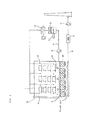
- numeral 1 indicates a furnace body of a shuttle kiln. Although three carriages 20 placed in the furnace are shown in Fig. 1 for simplification, actually the furnace body 1 extends horizontally and an entry door 21 is opened to allow many carriages to enter the furnace body 1 for firing. On the bottom surface of each of the carriages 20, a gas flow path 2 is formed. At the lower part of each carriage, a gas suction path 4 including a gas suction port 3 is placed at a position facing the gas flow paths 2. As described above, since the shuttle kiln needs to have a traveling mechanism for the carriages 20, the lower part of the furnace body cannot be sealed completely.
- the gas suction path 4 some fresh air having entered from the outside as denoted by an arrow can be prevented from entering the furnace body because it is suctioned to the gas suction path 4 together with the in-furnace gas.
- the gas is not limited to be suctioned through the lower part of the carriage because it can be drawn in through the top or rear wall of the furnace body 1 depending on a furnace structure.
- the gas suction path 4 includes an afterburner 5 and a suction fan 6.
- the organic binder contained in the ceramic porous bodies evaporates and therefore vapor of the organic binder is contained also in in-furnace gas suctioned to the gas suction path 4.
- the organic binder vapor is completely burned by the afterburner 5 and released into the atmosphere.
- the shuttle kiln of the invention includes a circulation path 7 in addition to the gas suction path 4.
- the circulation path 7 is used to suction the in-furnace gas from the furnace through a circulating suction port 13 formed in a side wall of the furnace body 1 and burn the organic binder gases and then draw it back into the furnace through a circulating return port 14.
- the circulating suction port 13 and the circulating return port 14 should preferably be disposed to positions where they may not disturb a flow of the in-furnace gas.
- the in-furnace gas may be suctioned by a circulation fan 8 through the circulating suction port 13 formed at a plurality of positions on the lower part of the side wall of the furnace body 1 and drawn back into the furnace via the circulating return port 14 formed at those multiple positions.
- a downward flow should preferably be formed in the furnace.
- the gas is suctioned from the lower part of the side wall and drawn back from the upper part of the side wall.
- those ports need not always be disposed to those positions. In some cases, the gas can be drawn from the upper part of the side wall or the top portion and drawn back from the lower part of the side wall.
- the circulation path 7 includes a combustion device 9 for burning the organic binder gases contained in the suctioned in-furnace gas.
- the combustion device 9, which should preferably be a catalytic reactor vessel, serves to burn the organic binder gases contained in the in-furnace gas and consume oxygen in the in-furnace gas through the burning so that the oxygen concentration may lower.
- the catalytic reactor vessel is made up of, for example, a ceramic honeycomb structure containing a precious-metal oxidation catalyst such as platinum or palladium and, therefore, can progress catalytic combustion even in condition where the organic binder gas concentration is low or in the condition that the oxygen concentration is low.
- the catalytic reactor vessel is not limited to this type.
- a heating device 10 is mounted to the stage preceding the catalytic reactor vessel to increase the temperature of the suctioned in-furnace gas to, for example, about 300°C. Further, since the in-furnace gas temperature is increased by catalytic combustion, if the gas is returned directly into the furnace body 1, the in-furnace temperature is disturbed. Therefore, it is preferable to provide, at a stage following the catalytic reactor vessel, a cooling device 11 for lowering the temperature of the gas having passed through the catalytic reactor vessel to about a predetermined in-furnace temperature.
- the heating device 10 is a gas burner or an electric heater and the cooling device 11 is a heat exchanger.
- the circulation path 7 is used in the binder releasing process in the early temperature rising phase and stopped in a firing process in which firing is performed at a higher temperature.
- a fuel gas supply pipe 15 can be disposed to the stage preceding the catalytic reactor vessel, as shown in Fig. 3 . Fuel gas supplied from the fuel gas supply pipe 15 may be burned in the catalytic reactor vessel to consume oxygen contained in the in-furnace gas in order to lower the oxygen concentration.
- An embodiment shown in Fig. 3 has a configuration in which the heating device 10 is provided to the stage preceding the catalytic reactor vessel to increase the temperature of the suctioned in-furnace gas to a catalyst activation temperature so that combustion may be enabled under the condition of a higher catalyst activation level.
- the heating device 10 is omitted and only the fuel gas supply pipe 15 is disposed to the stage preceding the catalytic reactor vessel, as shown in Fig.
- a shuttle kiln of the invention having such a configuration may be used, similarly to conventional methods, to fire unfired ceramic porous bodies containing organic binders, for example, a ceramic honeycomb structure.
- in-furnace gas and fresh air which enters the furnace body 1 through its lower portion are suctioned to the gas suction path 4 to burn and deodorize the contained organic binder gases with the afterburner 5, while at the same time the in-furnace gas is suctioned to the circulation path 7 through the circulating suction port 13 formed in the side wall of the furnace body 1.
- the in-furnace gas drawn to the circulation path 7 is heated by the heating device 10 to an activation temperature area of the oxidation catalyst and then passes through the catalytic reactor vessel.
- the contained organic binder gases undergoes catalytic combustion, and therefore the gas having passed through the catalytic reactor vessel is lower in organic binder gases concentration and also in oxygen concentration, and is cooled by the cooling device 11 to the predetermined in-furnace temperature and returned into the furnace body 1 through the circulating return port 14.
- the in-furnace oxygen concentration can be reduced to 8% or less as a target value, or preferably 5% or less.
- organic binder gases generating from the ceramic porous bodies is also removed through catalytic combustion so that its concentration can be maintained at a low level of about 1/4 of the explosion limit.
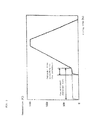
- the in-furnace temperature needs to be raised moderately as shown in Fig. 2 , but it is not always easy to control combustion of the many burners 12 placed in the furnace body 1.
- the in-furnace temperature can be easily and accurately controlled by controlling only the heating device 10 placed on the circulation path 7 while holding the many burners 12 placed in the furnace body 1 in an unignited state in the binder releasing process.
- a shuttle kiln of the invention it is possible to arbitrarily control the gas circulation speed (gas circulation amount) along the circulation path 7 without influencing the in-furnace temperature.
- the conventional shuttle kiln not provided with the circulation path 7 to control the oxygen concentration to 8% or less, or preferably 5% or less, the amount of air that can be drawn into the furnace must be limited, which causes a problem that stirring in the furnace becomes insufficient or the organic binder gas concentration increases.
- the binder releasing process can be progressed efficiently while preventing the occurrence of breaks on ceramic porous bodies to thereby reduce the overall firing time to about 2/3 of the conventional value. Therefore, with a furnace having the same capacity as the conventional one, productivity can be improved to about 1.5-fold. Moreover, the in-furnace organic binder gas concentration can be controlled to a level much lower than the explosion limit and an advantage of excellent safety can be obtained.
Landscapes
- Engineering & Computer Science (AREA)
- Chemical & Material Sciences (AREA)
- Ceramic Engineering (AREA)
- Manufacturing & Machinery (AREA)
- Materials Engineering (AREA)
- Structural Engineering (AREA)
- Organic Chemistry (AREA)
- General Engineering & Computer Science (AREA)
- Inorganic Chemistry (AREA)
- Mechanical Engineering (AREA)
- Dispersion Chemistry (AREA)
- Furnace Details (AREA)
- Waste-Gas Treatment And Other Accessory Devices For Furnaces (AREA)
- Tunnel Furnaces (AREA)
- Feeding, Discharge, Calcimining, Fusing, And Gas-Generation Devices (AREA)
Abstract
Description
- The invention relates to a shuttle kiln for firing ceramic porous bodies containing organic binders, and more specifically to a shuttle kiln suitable for firing ceramic honeycomb structures.
- As a furnace for firing ceramic porous bodies to be mass-produced, a continuous-type furnace represented by a tunnel kiln or a roller hearth kiln and a batch-type furnace represented by a shuttle kiln are widely used. The shuttle kiln is a batch-type firing furnace for firing porous materials loaded on a carriage stored in the furnace and is named so because the carriage reciprocates between the inside and the outside of the furnace.
- In firing of ceramic porous bodies containing organic binders in the shuttle kiln, in an early phase of temperature rising, a large amount of organic binder vapor generates from the unfired ceramic porous bodies. To secure safety in this phase, it is necessary to control the concentration of the organic binder vapor in the furnace to a level below the explosion limit. Typical examples of organic binder are methylcellulose, polyvinyl alcohol, etc.
- Typically, a burner is ignited at high excess air ratio m of 30 to 50, and its burner flame speed is increased to stir the inside of the furnace efficiently and also introduce a large amount of air into the furnace in order to control the concentration of the organic binder vapor to a level below the explosion limit. Therefore, naturally, an oxygen concentration in the furnace rises to burn the organic binder vapor at the surface of the ceramic porous bodies. However, since ceramic porous bodies such as a ceramic honeycomb structure have excellent thermal insulation properties, the following problems occur.
- That is, in the early phase, as the organic binder vapor burns, a periphery of the ceramic porous body is heated to promote releasing of binder. However, the heat of the ceramic porous body is hardly transferred to the inside because of its excellent thermal insulation properties. Then, as the internal temperature rises gradually, the organic binder in the furnace burns progressively so that the internal temperature of the ceramic porous body may start rising. However, the heat does not easily transfer to the periphery of the ceramic porous body, and its inside temperature becomes higher than periphery. Consequently, tensile force acts inside the ceramic porous body in the early phase of a binder releasing process and, by contrast, acts outside in the later phase of the process. As a result, the ceramic porous body is liable to have cracks referred to as "breaks" and therefore be defective.
- To avoid such problem, the rate of temperature rise in the furnace can be decreased to slow down the binder releasing process. At the same time, however, the firing cycle is prolonged, inevitably resulting in decrease in productivity.
- To solve the problem,
Patent Document 1 according to the application by the present applicant discloses a technology of decreasing the concentration of oxygen in the furnace in the binder releasing process to thereby suppress burning of organic binders so that the cracks occurrence may be prevented. As specific means for the purpose, a method of reducing the air ratio of a burner and a method of introducing a nitrogen gas is described. - In the case of a ceramic honeycomb structure, to suppress a temperature difference that causes the cracks, the oxygen concentration should be kept at 8% or less, or preferably 5% or less. However, this is accompanied by cost-related problems because, for example, a large amount of nitrogen gas is required. Further, if the burner's air ratio is decreased to lower the in-furnace oxygen concentration, stirring in the furnace cannot become well due to an insufficient amount of the internal gas and its internal temperature distribution is liable to be inhomogeneous.
-
Patent Document 2 describes another method to lower the in-furnace oxygen concentration by use of a large amount of low-oxygen gas, specifically by suctioning an in-furnace gas containing organic binders gas, completely burning it with an afterburner, and drawing back the generated combustion gas into the furnace. - However, in the case of a batch-type furnace represented by a shuttle kiln, a suction port for the in-furnace gas is exposed to a high temperature of 1000°C or higher during a firing process following the binder releasing process and cannot be sealed completely; therefore, not a small amount of fresh air is mixed when the in-furnace gas is suctioned. Moreover, in the case of a shuttle kiln, as a carriage needs to reciprocate between the inside and the outside of the furnace, if the in-furnace suction port is formed at the lower part of the furnace body, namely in the carriage, it is very difficult to seal a portion between the port and a smoke path inlet port located at a lower part of the carriage. Therefore, fresh air is mixed inevitably when the in-furnace gas is suctioned. As a result, the oxygen concentration of combustion gas generated via the afterburner decreases only to about 10%, causing a problem that even if the combustion gas is drawn back into the furnace, the oxygen concentration in the furnace cannot be kept at a sufficiently low level.
-
- Patent Document 1:
JP H1-203273 A - Patent Document 2:
JP 2001-524451 W - In view of the above, it is an object of the invention to solve the conventional problems and provide a shuttle kiln that can fire ceramic porous bodies containing organic binders in a shorter period of time than in conventional methods without generating a break due to a temperature difference between the inside and the outside.
- To solve the problems, the invention provides a shuttle kiln for firing ceramic porous bodies containing organic binders. The kiln includes a gas suction path for suctioning an in-furnace gas and exhausting it via the afterburner, and a circulation path for suctioning the in-furnace gas to the furnace outside, burning organic binder gases, and drawing back the in-furnace gas into the furnace.
- It is preferable to suction the in-furnace gas to the gas suction path from a top or bottom portion of the furnace body and suction the in-furnace gas to the circulation path from a side wall of the furnace body. Preferably the circulation path includes a catalytic reactor vessel for catalytic combustion of the suctioned-furnace gas, a fuel gas supply pipe mounted at a stage preceding the catalytic reactor vessel and used to supply a fuel gas, a heating device mounted at the stage preceding the catalytic reactor vessel and used to heat the suctioned in-furnace gas, and a cooling device mounted at a stage following the catalytic reactor vessel and used to lower a temperature of the gas having passed through the catalytic reactor vessel to a predetermined temperature. Further, the ceramic porous bodies containing the organic binder can be of honeycomb structures. Further, preferably the circulation path is operated during binder releasing process and has a function of keeping an in-furnace oxygen concentration at 8% or less, or preferably 5% or less.
- A shuttle kiln of the invention includes a gas suction path for suctioning in an in-furnace gas and exhausting it via an afterburner and another path, namely, a circulation path for suctioning the in-furnace gas to the furnace outside, burning organic binder gases, and drawing back the in-furnace gas into the furnace. With this configuration, the in-furnace gas can be circulated without allowing mixing of fresh air, and an oxygen concentration can be reduced to a desired level because oxygen in the in-furnace gas are consumed through combustion. At the same time, as the organic binders are also burned, its concentration can be lowered to easily control the concentration of the in-furnace organic binder gases to a level below the explosion limit. Moreover, by increasing the speed of circulation, stirring in the furnace can be promoted to prevent the in-furnace temperature distribution from becoming inhomogeneous.
- Further, the shuttle kiln of the invention includes the gas suction path for suctioning the in-furnace gas and exhausting it via the afterburner and, therefore, can suction fresh air, which has inevitably entered the furnace, along with the in-furnace gas, burn the contained organic binder gases, and then exhaust it.
- Therefore, according to the shuttle kiln of the invention, as binder releasing process can be performed while inhibiting the organic binder gases from burning on the surface of a ceramic porous bodies and a temperature difference between the inside and the outside of the ceramic porous bodies can be reduced, no breaks occur. Further, as the binder releasing process can be progressed by increasing a rate of temperature rise, a firing time can be shortened. Moreover, as nitrogen gas etc. need not be used, increase in running costs can be prevented.
- Further, by providing a heating device, a catalytic reactor vessel, and a cooling device for the in-furnace gas suctioned the circulation path, the in-furnace gas can be heated to promote catalytic combustion. In addition, as the gases having passed through the catalytic reactor vessel is cooled by the cooling device to a predetermined temperature and then returned into the furnace, the in-furnace temperature does not fluctuate.
- Furthermore, it is not easy to control combustion of many burners placed in the furnace body because the in-furnace temperature needs to be raised moderately in the binder releasing process; however, according to the shuttle kiln of the invention, as the many burners placed in the furnace body can be stopped in combustion to control temperature by using only the heating device mounted along the circulation path, the in-furnace temperature can be raised moderately.
-
-
Fig. 1 is a schematic diagram showing an embodiment of the invention; -
Fig. 2 is a graph showing changes in firing temperature; -
Fig. 3 is a schematic diagram showing another embodiment; and -
Fig. 4 is a schematic diagram showing a further embodiment. - Preferred embodiments of the invention will be described below. In the present embodiment, what is to be fired are ceramic honeycomb structures, namely ceramic porous bodies containing organic binders. The unfired ceramic porous bodies are loaded on a carriage and carried into a furnace to evaporate the organic binder at about 200°C and then fired at an elevated temperature of about 1500°C.
- In
Fig. 1 ,numeral 1 indicates a furnace body of a shuttle kiln. Although threecarriages 20 placed in the furnace are shown inFig. 1 for simplification, actually thefurnace body 1 extends horizontally and anentry door 21 is opened to allow many carriages to enter thefurnace body 1 for firing. On the bottom surface of each of thecarriages 20, agas flow path 2 is formed. At the lower part of each carriage, agas suction path 4 including agas suction port 3 is placed at a position facing thegas flow paths 2. As described above, since the shuttle kiln needs to have a traveling mechanism for thecarriages 20, the lower part of the furnace body cannot be sealed completely. However, by providing thegas suction path 4, some fresh air having entered from the outside as denoted by an arrow can be prevented from entering the furnace body because it is suctioned to thegas suction path 4 together with the in-furnace gas. In this case, the gas is not limited to be suctioned through the lower part of the carriage because it can be drawn in through the top or rear wall of thefurnace body 1 depending on a furnace structure. - The
gas suction path 4 includes anafterburner 5 and asuction fan 6. During the binder releasing process in an early phase of temperature rising, the organic binder contained in the ceramic porous bodies evaporates and therefore vapor of the organic binder is contained also in in-furnace gas suctioned to thegas suction path 4. The organic binder vapor is completely burned by theafterburner 5 and released into the atmosphere. - The shuttle kiln of the invention includes a
circulation path 7 in addition to thegas suction path 4. Thecirculation path 7 is used to suction the in-furnace gas from the furnace through a circulatingsuction port 13 formed in a side wall of thefurnace body 1 and burn the organic binder gases and then draw it back into the furnace through a circulatingreturn port 14. By providing thecirculation path 7 in addition to thegas suction path 4, it is possible to reduce the burden on and down size of the afterburner as compared to a method that includes only thegas suction path 4 to suction the whole amount of in-furnace gas containing organic binder gases to thegas suction path 4, completely burn it with the afterburner, and draw back the resultant combustion gas into the furnace. - The circulating
suction port 13 and the circulatingreturn port 14 should preferably be disposed to positions where they may not disturb a flow of the in-furnace gas. In the present embodiment, the in-furnace gas may be suctioned by acirculation fan 8 through the circulatingsuction port 13 formed at a plurality of positions on the lower part of the side wall of thefurnace body 1 and drawn back into the furnace via the circulatingreturn port 14 formed at those multiple positions. Generally, from the viewpoint of in-furnace temperature distribution and thermal efficiency, a downward flow should preferably be formed in the furnace. For this purpose, in the present embodiment, the gas is suctioned from the lower part of the side wall and drawn back from the upper part of the side wall. However, those ports need not always be disposed to those positions. In some cases, the gas can be drawn from the upper part of the side wall or the top portion and drawn back from the lower part of the side wall. - The
circulation path 7 includes acombustion device 9 for burning the organic binder gases contained in the suctioned in-furnace gas. Thecombustion device 9, which should preferably be a catalytic reactor vessel, serves to burn the organic binder gases contained in the in-furnace gas and consume oxygen in the in-furnace gas through the burning so that the oxygen concentration may lower. The catalytic reactor vessel is made up of, for example, a ceramic honeycomb structure containing a precious-metal oxidation catalyst such as platinum or palladium and, therefore, can progress catalytic combustion even in condition where the organic binder gas concentration is low or in the condition that the oxygen concentration is low. However, the catalytic reactor vessel is not limited to this type. - Since catalyst activity of the catalytic reactor vessel is influenced by the temperature, a
heating device 10 is mounted to the stage preceding the catalytic reactor vessel to increase the temperature of the suctioned in-furnace gas to, for example, about 300°C. Further, since the in-furnace gas temperature is increased by catalytic combustion, if the gas is returned directly into thefurnace body 1, the in-furnace temperature is disturbed. Therefore, it is preferable to provide, at a stage following the catalytic reactor vessel, acooling device 11 for lowering the temperature of the gas having passed through the catalytic reactor vessel to about a predetermined in-furnace temperature. Theheating device 10 is a gas burner or an electric heater and thecooling device 11 is a heat exchanger. Thecirculation path 7 is used in the binder releasing process in the early temperature rising phase and stopped in a firing process in which firing is performed at a higher temperature. - In a case where the concentration of the organic binder gases contained in the in-furnace gas is too low to decrease the oxygen concentration by sufficiently consuming oxygen contained in the in-furnace gas only through the resultant combustion, a fuel
gas supply pipe 15 can be disposed to the stage preceding the catalytic reactor vessel, as shown inFig. 3 . Fuel gas supplied from the fuelgas supply pipe 15 may be burned in the catalytic reactor vessel to consume oxygen contained in the in-furnace gas in order to lower the oxygen concentration. - An embodiment shown in
Fig. 3 has a configuration in which theheating device 10 is provided to the stage preceding the catalytic reactor vessel to increase the temperature of the suctioned in-furnace gas to a catalyst activation temperature so that combustion may be enabled under the condition of a higher catalyst activation level. However, even a simple configuration in which theheating device 10 is omitted and only the fuelgas supply pipe 15 is disposed to the stage preceding the catalytic reactor vessel, as shown inFig. 4 , is capable of having an effect of consuming oxygen contained in the in-furnace gas to decrease the oxygen concentration in a case where the concentration of the organic binder gas concentration contained in the in-furnace gas is too low to decrease the oxygen concentration by sufficiently consuming oxygen contained in the in-furnace gas only through the resultant combustion. - A shuttle kiln of the invention having such a configuration may be used, similarly to conventional methods, to fire unfired ceramic porous bodies containing organic binders, for example, a ceramic honeycomb structure. In the binder releasing process in the early temperature rising phase, in-furnace gas and fresh air which enters the
furnace body 1 through its lower portion are suctioned to thegas suction path 4 to burn and deodorize the contained organic binder gases with theafterburner 5, while at the same time the in-furnace gas is suctioned to thecirculation path 7 through the circulatingsuction port 13 formed in the side wall of thefurnace body 1. The in-furnace gas drawn to thecirculation path 7 is heated by theheating device 10 to an activation temperature area of the oxidation catalyst and then passes through the catalytic reactor vessel. In this case, the contained organic binder gases undergoes catalytic combustion, and therefore the gas having passed through the catalytic reactor vessel is lower in organic binder gases concentration and also in oxygen concentration, and is cooled by the coolingdevice 11 to the predetermined in-furnace temperature and returned into thefurnace body 1 through the circulatingreturn port 14. - As the circulation process is repeated, oxygen in the furnace is consumed while air is prevented from entering the furnace through its lower part. Consequently, the in-furnace oxygen concentration can be reduced to 8% or less as a target value, or preferably 5% or less. Further, organic binder gases generating from the ceramic porous bodies is also removed through catalytic combustion so that its concentration can be maintained at a low level of about 1/4 of the explosion limit. In the binder releasing process in the early temperature rising phase, the in-furnace temperature needs to be raised moderately as shown in
Fig. 2 , but it is not always easy to control combustion of themany burners 12 placed in thefurnace body 1. However, according to the invention, the in-furnace temperature can be easily and accurately controlled by controlling only theheating device 10 placed on thecirculation path 7 while holding themany burners 12 placed in thefurnace body 1 in an unignited state in the binder releasing process. - In a shuttle kiln of the invention, it is possible to arbitrarily control the gas circulation speed (gas circulation amount) along the
circulation path 7 without influencing the in-furnace temperature. In the conventional shuttle kiln not provided with thecirculation path 7, to control the oxygen concentration to 8% or less, or preferably 5% or less, the amount of air that can be drawn into the furnace must be limited, which causes a problem that stirring in the furnace becomes insufficient or the organic binder gas concentration increases. In contrast, according to the invention, it is possible to arbitrarily increase the gas circulation speed (gas circulation amount) along thecirculation path 7 in the repetitive catalytic combustion process and, therefore, arbitrarily control the organic binder gas concentration while sufficiently stirring the inside of the furnace. - As described above, conventional methods require a long-time for releasing the binder to prevent occurrence of breaks in the binder releasing process. The behavior is denoted by a dotted line in
Fig. 2 . In contrast, if the shuttle kiln of the invention is used, it is possible to arbitrarily control the oxygen concentration as well as the organic binder gas concentration and, therefore, greatly reduce the binder releasing time to about 1/5 of the conventional value as denoted by a solid line inFig. 2 while securely preventing the occurrence of breaks. After the binder releasing process ends, the operation of thecirculation path 7 is stopped to perform firing at a high temperature by using themany burners 12 placed in thefurnace body 1. - As described hereinabove, according to the invention, by inhibiting rapid combustion of an organic binder by decreasing the oxygen concentration, the binder releasing process can be progressed efficiently while preventing the occurrence of breaks on ceramic porous bodies to thereby reduce the overall firing time to about 2/3 of the conventional value. Therefore, with a furnace having the same capacity as the conventional one, productivity can be improved to about 1.5-fold. Moreover, the in-furnace organic binder gas concentration can be controlled to a level much lower than the explosion limit and an advantage of excellent safety can be obtained.
-
- 1
- Furnace body
- 2
- Gas flow path
- 3
- Gas suction port
- 4
- Gas suction path
- 5
- Afterburner
- 6
- Suction fan
- 7
- Circulation path
- 8
- Circulation fan
- 9
- Combustion device
- 10
- Heating device
- 11
- Cooling device
- 12
- Burner
- 13
- Circulating suction port
- 14
- Circulating return port
- 15
- Fuel gas supply pipe
- 20
- Carriage
- 21
- Entry door
Claims (7)
- A shuttle kiln for firing ceramic porous bodies containing organic binders, the kiln comprising:a gas suction path for suctioning in an in-furnace gas and exhausting it via an afterburner and;a circulation path for suctioning the in-furnace gas to the furnace outside, burning an organic binder gas, and drawing back the in-furnace gas into the furnace.
- The shuttle kiln according to claim 1, wherein the in-furnace gas is suctioned to the gas suction path from a top or bottom portion of the furnace body and suctioned to the circulation path from a side wall of the furnace body.
- The shuttle kiln according to claim 1 or 2, wherein the circulation path is provided with a catalytic reactor vessel for catalytic combustion of the suctioned in-furnace gas.
- The shuttle kiln according to claim 3, comprising a fuel gas supply pipe mounted at a stage preceding the catalytic reactor vessel and used to supply a fuel gas.
- The shuttle kiln according to claim 3 or 4, wherein the circulation path comprises:a heating device mounted at the stage preceding the catalytic reactor vessel and used to heat the suctioned in-furnace gas; anda cooling device mounted at a stage following the catalytic reactor vessel and used to lower a temperature of the gas having passed through the catalytic reactor vessel to a predetermined temperature.
- The shuttle kiln according to any of claims 1 to 5, wherein the ceramic porous bodies containing the organic binder is of a ceramic honeycomb structure.
- The shuttle kiln according to any of claim 1 to 6, wherein the circulation path has a function to keep an in-furnace oxygen concentration at 8 % or less and is operated in a binder releasing process.
Applications Claiming Priority (2)
| Application Number | Priority Date | Filing Date | Title |
|---|---|---|---|
| JP2011058924 | 2011-03-17 | ||
| PCT/JP2012/056672 WO2012124761A1 (en) | 2011-03-17 | 2012-03-15 | Shuttle kiln for sintering ceramic porous body |
Publications (3)
| Publication Number | Publication Date |
|---|---|
| EP2687802A1 true EP2687802A1 (en) | 2014-01-22 |
| EP2687802A4 EP2687802A4 (en) | 2014-10-15 |
| EP2687802B1 EP2687802B1 (en) | 2018-03-07 |
Family
ID=46830826
Family Applications (1)
| Application Number | Title | Priority Date | Filing Date |
|---|---|---|---|
| EP12757553.8A Active EP2687802B1 (en) | 2011-03-17 | 2012-03-15 | Shuttle kiln for sintering ceramic porous body |
Country Status (6)
| Country | Link |
|---|---|
| US (1) | US9776922B2 (en) |
| EP (1) | EP2687802B1 (en) |
| JP (1) | JP5879628B2 (en) |
| CN (1) | CN103384807B (en) |
| MX (1) | MX362880B (en) |
| WO (1) | WO2012124761A1 (en) |
Families Citing this family (11)
| Publication number | Priority date | Publication date | Assignee | Title |
|---|---|---|---|---|
| US9332216B2 (en) * | 2014-03-12 | 2016-05-03 | Sony Computer Entertainment America, LLC | Video frame rate compensation through adjustment of vertical blanking |
| CN105806083B (en) * | 2014-12-31 | 2019-07-09 | 莆田市建仁建材有限责任公司 | Industrial waste gas CO2 is changed into CO second-time burning kiln and method |
| JP6691493B2 (en) * | 2017-02-24 | 2020-04-28 | 日本碍子株式会社 | Ceramic body manufacturing method |
| US11661379B2 (en) | 2017-07-21 | 2023-05-30 | Corning Incorporated | Methods of extracting volatiles from ceramic green bodies |
| JP7022593B2 (en) * | 2018-01-15 | 2022-02-18 | 日本碍子株式会社 | A method for manufacturing a ceramic fired body and a method for firing a ceramic molded body. |
| CN109028104A (en) * | 2018-07-17 | 2018-12-18 | 江苏泰瑞耐火有限公司 | The device and method of shuttle-type kiln exhaust gas second-time burning |
| CN110260654B (en) * | 2019-05-16 | 2021-01-22 | 湖南艾迪奥电子科技有限公司 | Glue discharging and sintering equipment for large-size magnetic core and manufacturing method thereof |
| CN110094969B (en) * | 2019-05-17 | 2024-02-06 | 中钢洛耐科技股份有限公司 | An energy-saving and environmentally friendly device for burning organic matter in nitriding kilns |
| US12392556B2 (en) | 2019-07-03 | 2025-08-19 | Corning Incorporated | Shuttle kiln exhaust configuration |
| JP7513188B2 (en) * | 2021-02-26 | 2024-07-09 | 株式会社島津製作所 | Degreasing Furnace |
| JP7517226B2 (en) * | 2021-03-31 | 2024-07-17 | 株式会社村田製作所 | Heat Treatment System |
Family Cites Families (22)
| Publication number | Priority date | Publication date | Assignee | Title |
|---|---|---|---|---|
| US1629253A (en) * | 1926-11-09 | 1927-05-17 | Oil Devices Corp | Means for controlling the combustion of hydrocarbons |
| US2795054A (en) * | 1954-10-07 | 1957-06-11 | Oxy Catalyst Inc | Method and apparatus for heat recovery from drying oven effluents |
| GB830136A (en) * | 1955-07-25 | 1960-03-09 | Castings Ltd | Furnaces or kilns |
| US3861334A (en) * | 1974-04-05 | 1975-01-21 | Air Preheater | Waste heat recovery |
| US4061463A (en) * | 1975-12-12 | 1977-12-06 | Burdett Manufacturing Company | Combustion system and method |
| US4217090A (en) * | 1978-08-22 | 1980-08-12 | B & K Machinery International Limited | Oven heating system |
| US4715810A (en) * | 1985-06-28 | 1987-12-29 | Aluminum Company Of America | Process and apparatus for removing volatiles from metal |
| DE3716444A1 (en) * | 1987-05-16 | 1988-12-01 | Hartmann Helmut | METHOD AND PLANT FOR CLEANING CONTAMINATED Bulk Goods |
| US4829703A (en) * | 1987-08-04 | 1989-05-16 | Gas Research Institute | Auxiliary flue for furnaces |
| JPH0745348B2 (en) | 1988-02-10 | 1995-05-17 | 日本碍子株式会社 | Firing method of ceramic honeycomb structure |
| US4995807A (en) * | 1989-03-20 | 1991-02-26 | Bryan Steam Corporation | Flue gas recirculation system |
| US5554350A (en) * | 1994-12-15 | 1996-09-10 | Combustion Engineering, Inc. | Air pollution control and heat recovery system and process for coal fired power plant |
| US5795146A (en) * | 1996-05-23 | 1998-08-18 | Btu International, Inc. | Furnace chamber having eductor to enhance thermal processing |
| JP2001524450A (en) | 1997-12-02 | 2001-12-04 | コーニング インコーポレイテッド | Method for firing ceramic honeycomb body |
| ATE465140T1 (en) | 1997-12-02 | 2010-05-15 | Corning Inc | METHOD FOR FIRING CERAMIC HONEYCOMB STRUCTURES |
| US20020003322A1 (en) * | 1998-11-24 | 2002-01-10 | Dull Alan T. | Method for firing ceramic honeycomb bodies |
| JP4393008B2 (en) * | 2001-03-26 | 2010-01-06 | 日本碍子株式会社 | Method for firing ceramic honeycomb body |
| JP4465648B2 (en) * | 2003-10-28 | 2010-05-19 | 日立金属株式会社 | Method for producing porous ceramic honeycomb structure |
| DE112004002205T5 (en) * | 2003-11-17 | 2006-10-05 | Ngk Insulators, Ltd., Nagoya | Oven and degreasing process |
| JP4523499B2 (en) * | 2005-06-27 | 2010-08-11 | 日本碍子株式会社 | Degreasing method |
| DE102008020600B4 (en) * | 2008-04-24 | 2010-11-18 | Outotec Oyj | Process and plant for the heat treatment of fine-grained mineral solids |
| WO2011146723A2 (en) * | 2010-05-19 | 2011-11-24 | Gillespie + Powers, Inc. | Wireless temperature sensing and control system for metal kiln and method of using the same |
-
2012
- 2012-03-15 CN CN201280009807.0A patent/CN103384807B/en active Active
- 2012-03-15 MX MX2013010494A patent/MX362880B/en active IP Right Grant
- 2012-03-15 JP JP2013504768A patent/JP5879628B2/en active Active
- 2012-03-15 WO PCT/JP2012/056672 patent/WO2012124761A1/en not_active Ceased
- 2012-03-15 EP EP12757553.8A patent/EP2687802B1/en active Active
-
2013
- 2013-09-10 US US14/022,619 patent/US9776922B2/en active Active
Non-Patent Citations (2)
| Title |
|---|
| No further relevant documents disclosed * |
| See also references of WO2012124761A1 * |
Also Published As
| Publication number | Publication date |
|---|---|
| JPWO2012124761A1 (en) | 2014-07-24 |
| EP2687802A4 (en) | 2014-10-15 |
| CN103384807B (en) | 2016-01-20 |
| US9776922B2 (en) | 2017-10-03 |
| CN103384807A (en) | 2013-11-06 |
| WO2012124761A1 (en) | 2012-09-20 |
| JP5879628B2 (en) | 2016-03-08 |
| MX2013010494A (en) | 2013-10-01 |
| EP2687802B1 (en) | 2018-03-07 |
| US20140011151A1 (en) | 2014-01-09 |
| MX362880B (en) | 2019-02-20 |
Similar Documents
| Publication | Publication Date | Title |
|---|---|---|
| EP2687802B1 (en) | Shuttle kiln for sintering ceramic porous body | |
| EP2687801B1 (en) | Tunnel kiln for firing porous ceramic material | |
| KR100297030B1 (en) | How to heat or dissolve the charges in a flame furnace | |
| US20030205573A1 (en) | Microwave firing furnace and microwave firing method | |
| US9073792B2 (en) | Methods for improved atmosphere control through secondary gas pressure wave firing | |
| US11920786B2 (en) | Regenerative burner, industrial furnace and method for producing a fired article | |
| KR101149371B1 (en) | Gas circulation device for coke oven | |
| JP2020085282A (en) | Industrial furnace and combustion control method for industrial furnace | |
| JP2005331162A (en) | Continuous furnace | |
| JP7676301B2 (en) | Method for controlling a gas-fueled furnace | |
| CN218994079U (en) | Kiln waste gas treatment device | |
| JP2003214603A (en) | Reducing combustion burner apparatus and non-oxidation kiln | |
| CN223121933U (en) | Noble metal roasting furnace constant temperature equipment | |
| JP2706550B2 (en) | Manufacturing method of carbon rod | |
| JP3370839B2 (en) | Radiant tube burner and atmosphere firing furnace using the same | |
| JP2017039612A (en) | Firing method and firing furnace | |
| JP4970086B2 (en) | Operation method of continuous heating furnace and continuous heating furnace | |
| JP5329777B2 (en) | Temperature control method for low oxygen atmosphere and temperature control system for low oxygen atmosphere | |
| JP5374061B2 (en) | Firing furnace for electronic parts and its pressure control method | |
| CN105318719A (en) | Car-bottom roasting furnace and use method | |
| JP2009063198A (en) | Burner furnace and heating method of burner furnace | |
| JPS6343673B2 (en) |
Legal Events
| Date | Code | Title | Description |
|---|---|---|---|
| PUAI | Public reference made under article 153(3) epc to a published international application that has entered the european phase |
Free format text: ORIGINAL CODE: 0009012 |
|
| 17P | Request for examination filed |
Effective date: 20130919 |
|
| AK | Designated contracting states |
Kind code of ref document: A1 Designated state(s): AL AT BE BG CH CY CZ DE DK EE ES FI FR GB GR HR HU IE IS IT LI LT LU LV MC MK MT NL NO PL PT RO RS SE SI SK SM TR |
|
| DAX | Request for extension of the european patent (deleted) | ||
| A4 | Supplementary search report drawn up and despatched |
Effective date: 20140911 |
|
| RIC1 | Information provided on ipc code assigned before grant |
Ipc: C04B 35/638 20060101ALI20140905BHEP Ipc: F27D 17/00 20060101AFI20140905BHEP Ipc: F27D 7/06 20060101ALI20140905BHEP Ipc: F27B 17/00 20060101ALI20140905BHEP |
|
| GRAP | Despatch of communication of intention to grant a patent |
Free format text: ORIGINAL CODE: EPIDOSNIGR1 |
|
| INTG | Intention to grant announced |
Effective date: 20171010 |
|
| GRAS | Grant fee paid |
Free format text: ORIGINAL CODE: EPIDOSNIGR3 |
|
| GRAA | (expected) grant |
Free format text: ORIGINAL CODE: 0009210 |
|
| AK | Designated contracting states |
Kind code of ref document: B1 Designated state(s): AL AT BE BG CH CY CZ DE DK EE ES FI FR GB GR HR HU IE IS IT LI LT LU LV MC MK MT NL NO PL PT RO RS SE SI SK SM TR |
|
| REG | Reference to a national code |
Ref country code: GB Ref legal event code: FG4D |
|
| REG | Reference to a national code |
Ref country code: CH Ref legal event code: EP Ref country code: AT Ref legal event code: REF Ref document number: 977019 Country of ref document: AT Kind code of ref document: T Effective date: 20180315 |
|
| REG | Reference to a national code |
Ref country code: DE Ref legal event code: R096 Ref document number: 602012043724 Country of ref document: DE |
|
| REG | Reference to a national code |
Ref country code: IE Ref legal event code: FG4D |
|
| REG | Reference to a national code |
Ref country code: NL Ref legal event code: MP Effective date: 20180307 |
|
| REG | Reference to a national code |
Ref country code: LT Ref legal event code: MG4D |
|
| PG25 | Lapsed in a contracting state [announced via postgrant information from national office to epo] |
Ref country code: HR Free format text: LAPSE BECAUSE OF FAILURE TO SUBMIT A TRANSLATION OF THE DESCRIPTION OR TO PAY THE FEE WITHIN THE PRESCRIBED TIME-LIMIT Effective date: 20180307 Ref country code: LT Free format text: LAPSE BECAUSE OF FAILURE TO SUBMIT A TRANSLATION OF THE DESCRIPTION OR TO PAY THE FEE WITHIN THE PRESCRIBED TIME-LIMIT Effective date: 20180307 Ref country code: ES Free format text: LAPSE BECAUSE OF FAILURE TO SUBMIT A TRANSLATION OF THE DESCRIPTION OR TO PAY THE FEE WITHIN THE PRESCRIBED TIME-LIMIT Effective date: 20180307 Ref country code: CY Free format text: LAPSE BECAUSE OF FAILURE TO SUBMIT A TRANSLATION OF THE DESCRIPTION OR TO PAY THE FEE WITHIN THE PRESCRIBED TIME-LIMIT Effective date: 20180307 Ref country code: FI Free format text: LAPSE BECAUSE OF FAILURE TO SUBMIT A TRANSLATION OF THE DESCRIPTION OR TO PAY THE FEE WITHIN THE PRESCRIBED TIME-LIMIT Effective date: 20180307 Ref country code: NO Free format text: LAPSE BECAUSE OF FAILURE TO SUBMIT A TRANSLATION OF THE DESCRIPTION OR TO PAY THE FEE WITHIN THE PRESCRIBED TIME-LIMIT Effective date: 20180607 |
|
| REG | Reference to a national code |
Ref country code: AT Ref legal event code: MK05 Ref document number: 977019 Country of ref document: AT Kind code of ref document: T Effective date: 20180307 |
|
| PG25 | Lapsed in a contracting state [announced via postgrant information from national office to epo] |
Ref country code: SE Free format text: LAPSE BECAUSE OF FAILURE TO SUBMIT A TRANSLATION OF THE DESCRIPTION OR TO PAY THE FEE WITHIN THE PRESCRIBED TIME-LIMIT Effective date: 20180307 Ref country code: RS Free format text: LAPSE BECAUSE OF FAILURE TO SUBMIT A TRANSLATION OF THE DESCRIPTION OR TO PAY THE FEE WITHIN THE PRESCRIBED TIME-LIMIT Effective date: 20180307 Ref country code: BG Free format text: LAPSE BECAUSE OF FAILURE TO SUBMIT A TRANSLATION OF THE DESCRIPTION OR TO PAY THE FEE WITHIN THE PRESCRIBED TIME-LIMIT Effective date: 20180607 Ref country code: GR Free format text: LAPSE BECAUSE OF FAILURE TO SUBMIT A TRANSLATION OF THE DESCRIPTION OR TO PAY THE FEE WITHIN THE PRESCRIBED TIME-LIMIT Effective date: 20180608 Ref country code: LV Free format text: LAPSE BECAUSE OF FAILURE TO SUBMIT A TRANSLATION OF THE DESCRIPTION OR TO PAY THE FEE WITHIN THE PRESCRIBED TIME-LIMIT Effective date: 20180307 |
|
| PG25 | Lapsed in a contracting state [announced via postgrant information from national office to epo] |
Ref country code: AL Free format text: LAPSE BECAUSE OF FAILURE TO SUBMIT A TRANSLATION OF THE DESCRIPTION OR TO PAY THE FEE WITHIN THE PRESCRIBED TIME-LIMIT Effective date: 20180307 Ref country code: RO Free format text: LAPSE BECAUSE OF FAILURE TO SUBMIT A TRANSLATION OF THE DESCRIPTION OR TO PAY THE FEE WITHIN THE PRESCRIBED TIME-LIMIT Effective date: 20180307 Ref country code: NL Free format text: LAPSE BECAUSE OF FAILURE TO SUBMIT A TRANSLATION OF THE DESCRIPTION OR TO PAY THE FEE WITHIN THE PRESCRIBED TIME-LIMIT Effective date: 20180307 Ref country code: PL Free format text: LAPSE BECAUSE OF FAILURE TO SUBMIT A TRANSLATION OF THE DESCRIPTION OR TO PAY THE FEE WITHIN THE PRESCRIBED TIME-LIMIT Effective date: 20180307 Ref country code: EE Free format text: LAPSE BECAUSE OF FAILURE TO SUBMIT A TRANSLATION OF THE DESCRIPTION OR TO PAY THE FEE WITHIN THE PRESCRIBED TIME-LIMIT Effective date: 20180307 Ref country code: IT Free format text: LAPSE BECAUSE OF FAILURE TO SUBMIT A TRANSLATION OF THE DESCRIPTION OR TO PAY THE FEE WITHIN THE PRESCRIBED TIME-LIMIT Effective date: 20180307 |
|
| REG | Reference to a national code |
Ref country code: CH Ref legal event code: PL |
|
| PG25 | Lapsed in a contracting state [announced via postgrant information from national office to epo] |
Ref country code: SK Free format text: LAPSE BECAUSE OF FAILURE TO SUBMIT A TRANSLATION OF THE DESCRIPTION OR TO PAY THE FEE WITHIN THE PRESCRIBED TIME-LIMIT Effective date: 20180307 Ref country code: AT Free format text: LAPSE BECAUSE OF FAILURE TO SUBMIT A TRANSLATION OF THE DESCRIPTION OR TO PAY THE FEE WITHIN THE PRESCRIBED TIME-LIMIT Effective date: 20180307 Ref country code: SM Free format text: LAPSE BECAUSE OF FAILURE TO SUBMIT A TRANSLATION OF THE DESCRIPTION OR TO PAY THE FEE WITHIN THE PRESCRIBED TIME-LIMIT Effective date: 20180307 Ref country code: CZ Free format text: LAPSE BECAUSE OF FAILURE TO SUBMIT A TRANSLATION OF THE DESCRIPTION OR TO PAY THE FEE WITHIN THE PRESCRIBED TIME-LIMIT Effective date: 20180307 |
|
| REG | Reference to a national code |
Ref country code: BE Ref legal event code: MM Effective date: 20180331 Ref country code: DE Ref legal event code: R097 Ref document number: 602012043724 Country of ref document: DE |
|
| REG | Reference to a national code |
Ref country code: IE Ref legal event code: MM4A |
|
| PG25 | Lapsed in a contracting state [announced via postgrant information from national office to epo] |
Ref country code: LU Free format text: LAPSE BECAUSE OF NON-PAYMENT OF DUE FEES Effective date: 20180315 Ref country code: PT Free format text: LAPSE BECAUSE OF FAILURE TO SUBMIT A TRANSLATION OF THE DESCRIPTION OR TO PAY THE FEE WITHIN THE PRESCRIBED TIME-LIMIT Effective date: 20180709 |
|
| PLBE | No opposition filed within time limit |
Free format text: ORIGINAL CODE: 0009261 |
|
| STAA | Information on the status of an ep patent application or granted ep patent |
Free format text: STATUS: NO OPPOSITION FILED WITHIN TIME LIMIT |
|
| PG25 | Lapsed in a contracting state [announced via postgrant information from national office to epo] |
Ref country code: MC Free format text: LAPSE BECAUSE OF FAILURE TO SUBMIT A TRANSLATION OF THE DESCRIPTION OR TO PAY THE FEE WITHIN THE PRESCRIBED TIME-LIMIT Effective date: 20180307 Ref country code: DK Free format text: LAPSE BECAUSE OF FAILURE TO SUBMIT A TRANSLATION OF THE DESCRIPTION OR TO PAY THE FEE WITHIN THE PRESCRIBED TIME-LIMIT Effective date: 20180307 Ref country code: IE Free format text: LAPSE BECAUSE OF NON-PAYMENT OF DUE FEES Effective date: 20180315 |
|
| 26N | No opposition filed |
Effective date: 20181210 |
|
| GBPC | Gb: european patent ceased through non-payment of renewal fee |
Effective date: 20180607 |
|
| PG25 | Lapsed in a contracting state [announced via postgrant information from national office to epo] |
Ref country code: CH Free format text: LAPSE BECAUSE OF NON-PAYMENT OF DUE FEES Effective date: 20180331 Ref country code: SI Free format text: LAPSE BECAUSE OF FAILURE TO SUBMIT A TRANSLATION OF THE DESCRIPTION OR TO PAY THE FEE WITHIN THE PRESCRIBED TIME-LIMIT Effective date: 20180307 Ref country code: LI Free format text: LAPSE BECAUSE OF NON-PAYMENT OF DUE FEES Effective date: 20180331 Ref country code: BE Free format text: LAPSE BECAUSE OF NON-PAYMENT OF DUE FEES Effective date: 20180331 |
|
| PG25 | Lapsed in a contracting state [announced via postgrant information from national office to epo] |
Ref country code: FR Free format text: LAPSE BECAUSE OF NON-PAYMENT OF DUE FEES Effective date: 20180507 Ref country code: GB Free format text: LAPSE BECAUSE OF NON-PAYMENT OF DUE FEES Effective date: 20180607 |
|
| PG25 | Lapsed in a contracting state [announced via postgrant information from national office to epo] |
Ref country code: MT Free format text: LAPSE BECAUSE OF NON-PAYMENT OF DUE FEES Effective date: 20180315 |
|
| PG25 | Lapsed in a contracting state [announced via postgrant information from national office to epo] |
Ref country code: TR Free format text: LAPSE BECAUSE OF FAILURE TO SUBMIT A TRANSLATION OF THE DESCRIPTION OR TO PAY THE FEE WITHIN THE PRESCRIBED TIME-LIMIT Effective date: 20180307 |
|
| PG25 | Lapsed in a contracting state [announced via postgrant information from national office to epo] |
Ref country code: HU Free format text: LAPSE BECAUSE OF FAILURE TO SUBMIT A TRANSLATION OF THE DESCRIPTION OR TO PAY THE FEE WITHIN THE PRESCRIBED TIME-LIMIT; INVALID AB INITIO Effective date: 20120315 |
|
| PG25 | Lapsed in a contracting state [announced via postgrant information from national office to epo] |
Ref country code: MK Free format text: LAPSE BECAUSE OF NON-PAYMENT OF DUE FEES Effective date: 20180307 |
|
| PG25 | Lapsed in a contracting state [announced via postgrant information from national office to epo] |
Ref country code: IS Free format text: LAPSE BECAUSE OF FAILURE TO SUBMIT A TRANSLATION OF THE DESCRIPTION OR TO PAY THE FEE WITHIN THE PRESCRIBED TIME-LIMIT Effective date: 20180707 |
|
| PGFP | Annual fee paid to national office [announced via postgrant information from national office to epo] |
Ref country code: DE Payment date: 20260128 Year of fee payment: 15 |