EP2687795A1 - Ice-making device for refrigerator/freezer - Google Patents
Ice-making device for refrigerator/freezer Download PDFInfo
- Publication number
- EP2687795A1 EP2687795A1 EP11861126.8A EP11861126A EP2687795A1 EP 2687795 A1 EP2687795 A1 EP 2687795A1 EP 11861126 A EP11861126 A EP 11861126A EP 2687795 A1 EP2687795 A1 EP 2687795A1
- Authority
- EP
- European Patent Office
- Prior art keywords
- ice
- making
- making tray
- heater
- refrigerator
- Prior art date
- Legal status (The legal status is an assumption and is not a legal conclusion. Google has not performed a legal analysis and makes no representation as to the accuracy of the status listed.)
- Withdrawn
Links
Images








Classifications
-
- F—MECHANICAL ENGINEERING; LIGHTING; HEATING; WEAPONS; BLASTING
- F25—REFRIGERATION OR COOLING; COMBINED HEATING AND REFRIGERATION SYSTEMS; HEAT PUMP SYSTEMS; MANUFACTURE OR STORAGE OF ICE; LIQUEFACTION SOLIDIFICATION OF GASES
- F25D—REFRIGERATORS; COLD ROOMS; ICE-BOXES; COOLING OR FREEZING APPARATUS NOT OTHERWISE PROVIDED FOR
- F25D17/00—Arrangements for circulating cooling fluids; Arrangements for circulating gas, e.g. air, within refrigerated spaces
- F25D17/04—Arrangements for circulating cooling fluids; Arrangements for circulating gas, e.g. air, within refrigerated spaces for circulating air, e.g. by convection
- F25D17/06—Arrangements for circulating cooling fluids; Arrangements for circulating gas, e.g. air, within refrigerated spaces for circulating air, e.g. by convection by forced circulation
- F25D17/062—Arrangements for circulating cooling fluids; Arrangements for circulating gas, e.g. air, within refrigerated spaces for circulating air, e.g. by convection by forced circulation in household refrigerators
- F25D17/065—Arrangements for circulating cooling fluids; Arrangements for circulating gas, e.g. air, within refrigerated spaces for circulating air, e.g. by convection by forced circulation in household refrigerators with compartments at different temperatures
-
- F—MECHANICAL ENGINEERING; LIGHTING; HEATING; WEAPONS; BLASTING
- F25—REFRIGERATION OR COOLING; COMBINED HEATING AND REFRIGERATION SYSTEMS; HEAT PUMP SYSTEMS; MANUFACTURE OR STORAGE OF ICE; LIQUEFACTION SOLIDIFICATION OF GASES
- F25C—PRODUCING, WORKING OR HANDLING ICE
- F25C5/00—Working or handling ice
- F25C5/02—Apparatus for disintegrating, removing or harvesting ice
- F25C5/04—Apparatus for disintegrating, removing or harvesting ice without the use of saws
- F25C5/08—Apparatus for disintegrating, removing or harvesting ice without the use of saws by heating bodies in contact with the ice
-
- F—MECHANICAL ENGINEERING; LIGHTING; HEATING; WEAPONS; BLASTING
- F25—REFRIGERATION OR COOLING; COMBINED HEATING AND REFRIGERATION SYSTEMS; HEAT PUMP SYSTEMS; MANUFACTURE OR STORAGE OF ICE; LIQUEFACTION SOLIDIFICATION OF GASES
- F25C—PRODUCING, WORKING OR HANDLING ICE
- F25C5/00—Working or handling ice
- F25C5/20—Distributing ice
- F25C5/22—Distributing ice particularly adapted for household refrigerators
-
- F—MECHANICAL ENGINEERING; LIGHTING; HEATING; WEAPONS; BLASTING
- F25—REFRIGERATION OR COOLING; COMBINED HEATING AND REFRIGERATION SYSTEMS; HEAT PUMP SYSTEMS; MANUFACTURE OR STORAGE OF ICE; LIQUEFACTION SOLIDIFICATION OF GASES
- F25C—PRODUCING, WORKING OR HANDLING ICE
- F25C2305/00—Special arrangements or features for working or handling ice
- F25C2305/022—Harvesting ice including rotating or tilting or pivoting of a mould or tray
- F25C2305/0221—Harvesting ice including rotating or tilting or pivoting of a mould or tray rotating ice mould
-
- F—MECHANICAL ENGINEERING; LIGHTING; HEATING; WEAPONS; BLASTING
- F25—REFRIGERATION OR COOLING; COMBINED HEATING AND REFRIGERATION SYSTEMS; HEAT PUMP SYSTEMS; MANUFACTURE OR STORAGE OF ICE; LIQUEFACTION SOLIDIFICATION OF GASES
- F25D—REFRIGERATORS; COLD ROOMS; ICE-BOXES; COOLING OR FREEZING APPARATUS NOT OTHERWISE PROVIDED FOR
- F25D2317/00—Details or arrangements for circulating cooling fluids; Details or arrangements for circulating gas, e.g. air, within refrigerated spaces, not provided for in other groups of this subclass
- F25D2317/06—Details or arrangements for circulating cooling fluids; Details or arrangements for circulating gas, e.g. air, within refrigerated spaces, not provided for in other groups of this subclass with forced air circulation
- F25D2317/067—Details or arrangements for circulating cooling fluids; Details or arrangements for circulating gas, e.g. air, within refrigerated spaces, not provided for in other groups of this subclass with forced air circulation characterised by air ducts
Definitions
- the present invention relates to an ice-making device for refrigerator/freezer.
- a refrigerator/freezer is usually equipped with an ice-making device for making ice cubes utilizing cold air for freezing.
- Examples of the ice-making device disposed in the refrigerator/freezer are shown in Patent Documents 1 to 6.
- Ice cubes produced by the ice-making device for refrigerator/freezer usually have low transparency. Therefore, inventions have been made for improving transparency of ice cubes.
- the ice-making devices described in Patent Documents 1 to 6 also include such inventions.
- the ice-making devices described in Patent Documents 1 and 2 have structures in which a heater is disposed above an ice-making tray so that temperature is higher above the ice-making tray than below the same. Thus, ice cubes are produced in order from a lower part to an upper part in the ice-making tray. Thus, in the ice-making process, air in water is easily discharged from an upper part of the water so that transparent ice cubes without air can be produced.
- the ice-making device described in Patent Document 3 has also a structure in which a heater is disposed above an ice-making tray.
- the ice-making devices described in Patent Documents 4 to 6 have structures in which transparent ice cubes and cloudy ice cubes are produced in a combined state, and the transparent ice cubes and the cloudy ice cubes are severed from each other when the ice cubes are released from the ice-making tray, and the cloudy ice cubes are left in the ice-making tray while only the transparent ice cubes are released.
- an ice-making device for refrigerator/freezer comprises an ice-making chamber, an ice-making tray disposed in the ice-making chamber for making an ice cube by cold air blown into the ice-making chamber, a thermistor for measuring temperature in the ice-making tray, a heater for heating the ice-making tray from below, and a control unit for exercising operation control of refrigeration cycle and control of power supply to the heater on the basis of the temperature measured by the thermistor as determination criterion.
- the control unit controls progress of freezing by supplying power to the heater after supplying water to the ice-making tray, and a cold air discharge port of the ice-making chamber includes a distal discharge port directed toward a distal portion of the ice-making tray in a view from the cold air discharge port, and a proximal discharge port directed toward a proximal portion of the ice-making tray in a view from the cold air discharge port.
- an amount of discharge flow from the distal discharge port is set to be smaller than an amount of discharge flow from the proximal discharge port.
- the heater is attached to and intimately contacts with an underside of the ice-making tray, and the underside of the ice-making tray is sheltered with a cover.
- a spring attachment rib is formed on the underside of the ice-making tray, the cover is provided with a through hole through which the spring attachment rib passes, and the cover is pressed to the heater by a pressure of a spring attached to the spring attachment rib passing through the through hole.
- the ice-making tray in the ice-making device for refrigerator/freezer having the above-mentioned structure, includes a support stud on a longitudinal-direction end thereof, and the cover shelters the underside of the ice-making tray in a state where a ring formed at an end of the cover engages with the support stud.
- the cover in the ice-making device for refrigerator/freezer having the above-mentioned structure, is provided with a through hole through which a boss formed on the underside of the ice-making tray is exposed, and a screw is screwed into the boss exposed from the through hole so that the cover is held in a movable manner along an axis of the boss.
- a top surface of the cover is provided with a rib for pressing the heater to the ice-making tray.
- each of longitudinal rims of the ice-making tray is provided with an wind shield plate for preventing cold air blown from above from proceeding to an underside of the ice-making tray.
- the wind shield plate has a notch formed from an edge thereof.
- a cover attached to the underside of the ice-making tray shelters the heater, and a gap is formed between a rim of the cover and the opposing wind shield plate so as not to cause a contact therebetween when the ice-making tray is twisted for releasing of ice cubes.
- the water in the ice-making tray is frozen while being heated by the heater from below, a major core part of the produced ice cube becomes transparent though the surface thereof becomes uneven as a trace of bubbles discharged from the periphery.
- freezing proceeds uniformly in every part of the ice-making tray, it is easy to control the freezing speed by controlling the heater so that transparency of the ice cube can be improved.
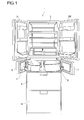
- a refrigerator/freezer 1 illustrated in Fig. 1 has a structure in which a cold chamber 2 with double doors 3L and 3R is disposed in the uppermost part, an ice-making chamber 4 with a door 5 and a freezing chamber 6 with a door 7 are disposed thereunder, a drawer type freezing chamber 8 is disposed thereunder, and a drawer type vegetable chamber 9 is disposed in the lowermost part.
- a refrigeration cycle (not shown) including a compressor and a heat exchanger generates cold air, which is distributed to each chamber through ducts, and hence cold storage temperature or freezing temperature necessary in each chamber is obtained. This mechanism is well known and is not described here in detail.
- an ice-making device 10 is disposed in a ceiling part of the ice-making chamber 4. A structure thereof is described below with reference to the drawings of Fig. 4 to Fig. 10 .
- Fig. 2 is a cross-sectional view of the ice-making device 10 viewed from the left side of the refrigerator/freezer 1.
- a duct 11 blowing cold air into the ice-making chamber 4.
- An ice-making tray casing 12 extends to the front from an upper end of the duct 11.
- An opening is formed in the underside of the ice-making tray casing 12 so that ice cubes produced in an ice-making tray can be dropped therethrough.
- the duct 11 is provided with a cold air discharge port 13 facing toward the inside of the ice-making tray casing 12.
- An ice-making tray 20 is disposed inside the ice-making tray casing 12 at a position for receiving the cold air blown from the cold air discharge port 13.
- the ice-making tray 20 is molded with synthetic resin that does not lose elasticity at low temperature. If bubbles in supplied water adhere to the inner surface of the ice-making tray 20, it is difficult to produce transparent ice cubes. Therefore, as means for preventing bubbles from adhering to the ice-making tray 20, it is preferable to use polypropylene mixed with silicone as molding material for the ice-making tray 20 or to coat the ice-making tray 20 with fluorocarbon resin after molding.
- Fine particles attracted by static electricity generated on the surface of the ice-making tray 20 also become obstacles to production of transparent ice cubes. Therefore, it is preferable to mold the ice-making tray 20 with a material that hardly generate static electricity, such as resin mixed with silicone or resin in which an antistatic agent is kneaded and mixed, or to apply an antistatic agent onto the ice-making tray 20 after molding.
- a material that hardly generate static electricity such as resin mixed with silicone or resin in which an antistatic agent is kneaded and mixed
- the ice-making tray 20 includes a total of eight ice-making cells 21 for producing ice cubes having a trapezoidal cross section.
- the eight ice-making cells 21 are arranged in two columns and four rows, and therefore the ice-making tray 20 has an elongated shape in a plan view. This elongated ice-making tray 20 is placed so that the longitudinal direction thereof coincides with the front-rear direction of the refrigerator/freezer 1.
- a support stud 22 is formed on a longitudinal-direction end of the ice-making tray 20, and a socket 23 is formed on an opposing end of the ice-making tray.
- the support stud 22 is supported in a rotatable manner by the ice-making tray casing 12.
- the socket 23 is connected to a shaft of an ice-releasing device 24 (see Fig. 3 ) disposed inside the ice-making tray casing 12 and is supported by the ice-releasing device 24.
- the support stud 22 and the socket 23 are disposed on the same horizontal axis.
- the ice-releasing device 24 includes a motor and a reduction gear which give the ice-making tray 20 rotation of a certain angle about the horizontal axis.
- a thermistor 25 On an underside of the ice-making tray 20, there is disposed a thermistor 25 at a position between two rows of the ice-making cells 21.
- the thermistor 25 measures temperature inside the ice-making cell 21 through a wall of the ice-making cell 21.
- the thermistor 25 is fixed by a thermistor cover 26.
- Pins 27 protrude from four corners of the thermistor cover 26 in the direction perpendicular to the longitudinal direction of the ice-making tray 20.
- a total of four legs 28 protrude from the underside of the ice-making tray 20 so as to surround the thermistor 25.
- a horizontal through hole 29 for the pin 27 to pass through the leg 28 is formed on the tip of the leg 28.
- a thermistor protection sealer 30 is placed on the thermistor 25, the thermistor cover 26 is placed thereon, and the pin 27 is engaged in the horizontal through hole 29 of the leg 28, so that the thermistor 25 is fixed.
- a heater 31 illustrated in Fig. 5 is disposed in addition to the thermistor 25.
- the heater 31 is formed by coating a heater wire with silicone resin, and an entirety thereof is flexible so as to conform to a twist of the ice-making tray 20.
- Parallel ribs 32 for receiving the heater 31 are formed on a top of each ice-making cell 21 in an upside down state.
- the parallel ribs 32 include two ribs disposed in parallel at a predetermined interval, and the interval between the ribs is determined so that the heater 31 is received between the ribs in a loose fit manner.
- the interval between the ribs is determined in this way for a purpose that the heater 31 can move freely to a certain extent when the ice-making tray 20 is twisted.
- the heater 31 is laid so as to form a symmetric shape in the left and right with respect to the longitudinal center line of the ice-making tray 20.
- an outline of the heater 31 is substantially a U-shape.
- a pair of power supply lines 33 is connected to open ends of the U-shape.
- the heater 31 Being designed to generate a small amount of heat, the heater 31 has a structure in which very thin heater wire is wound around a glass fiber core. Therefore, if the heater 31 is twisted in a direction in which the winding is tightened, the heater wire may easily be severed. Therefore, as described above, the heater 31 can move freely to a certain extent, and the layout of the heater 31 is shaped such that an excessive force is not applied to the heater wire as much as possible.
- the underside of the ice-making tray 20 is sheltered with a cover 34.
- the cover 34 prevents the cold air from entering into an underside space of the ice-making tray 20 and makes temperature distribution among the ice-making cells 21 become uniform.
- the cover 34 plays a role of keeping the heater 31 between the parallel ribs 32.
- the cover 34 has a rectangular tray shape, and a ring 35 for the support stud 22 to pass through is formed at one end thereof. After the ring 35 is engaged with the support stud 22, the cover 34 is attached to the ice-making tray 20 with two screws 36 and one spring 37.
- the attachment of the cover 34 is not a firm one restricting movement of the ice-making tray 20 but a flexible one not hampering twist of the ice-making tray 20 when ice cubes are released. It is preferable to mold the cover 34 with synthetic resin that does not lose elasticity at low temperature, similarly to the ice-making tray 20.
- Two through holes 38 are formed near both ends in the longitudinal direction of the cover 34.
- two through holes 39 are formed symmetrically with respect to the longitudinal center line at a position closer to the center of the cover 34 than the through holes 38.
- the through hole 38 has a circular shape and a boss 40 having a circular cross-section shape formed on the underside of the ice-making tray 20 passes through the through hole 38.
- the through hole 39 has a rectangular shape and a spring attachment rib 41 formed on the underside of the ice-making tray 20 passes through the through hole 39.
- the cover 34 is held in a movable manner along the axes of the bosses 40 with the screws 36 as drop-off stoppers. In other words, the screws 36 do not fasten the cover 34 but prevent the cover 34 from disengaging from the ice-making tray 20.
- the spring attachment ribs 41 protrude from the through holes 39 of the cover 34 as illustrated in Fig. 6 .
- Attachment hooks 43 on both ends of the spring 37 are engaged with horizontal through holes 42 formed on the tips of the spring attachment ribs 41.
- the spring 37 is made by bending and forming a spring steel wire in a shape having the attachment hooks 43 in the middle in the longitudinal direction and hairpin portions 44 at both ends in the longitudinal direction.
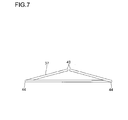
- the hairpin portion 44 extends at a downward slant in Fig. 6 , namely in the direction of the ice-making tray 20. As illustrated in Fig. 7 , the hairpin portions 44 are lower than the attachment hooks 43 in the spring 37, and a linear portion connecting the hairpin portions 44 is horizontal. Therefore, if the attachment hooks 43 are engaged with the horizontal through holes 42 of the spring attachment rib 41, the hairpin portions 44 and the linear portion connecting the hairpin portions 44 exert pressure on the cover 34. The cover 34 is pressed to the heater 31 as illustrated in Fig. 3 , and hence the heater 31 is held by a constant load so as not to disengage from the parallel ribs 32. In this way, the heater 31 intimately contacts with the ice-making cell 21 so that heat of the heater 31 can be efficiently conducted to the ice-making cell 21.
- ribs 34a for pressing the heater 31 to the ice-making tray 20 are formed along the shape of the heater 31 and on the top surface of the cover 34. Thanks to the ribs 34a, contact area between the heater 31 and the cover 34 can be reduced so that sliding between the heater 31 and the cover 34, which is inevitably generated when the ice-making tray 20 is twisted, becomes smooth. In addition, strength of the cover 34 is enhanced by the ribs 34a.
- a lateral rib 34b connecting the ribs 34a.
- a position of the rib 34b corresponds to a position at which the spring 37 presses the cover 34. Therefore, pressure from the spring 37 can be transmitted uniformly to the heater 31.
- the rib 34b is also useful for reinforcement of the cover 34.
- a low-lying rib 31a illustrated in Fig. 9 and Fig. 10 .
- the rib 31a is useful for distinguishing whether the heater 31 is disposed in a twisted state or not.
- a wind shield plate 45 On each of longitudinal rims of the ice-making tray 20, there is integrally formed a wind shield plate 45 extending downward.
- the wind shield plate 45 prevents the cold air blown from above to the ice-making tray 20 from proceeding to a lower portion of the ice-making tray 20. Therefore, it is possible to reduce loss of heating effect of the heater 31 caused by the cold air having entered into the underside space of the ice-making tray 20, and let the cold air concentrate on the top of the ice-making tray 20.
- notches 46 vertically from the edge at positions corresponding to boundaries between the ice-making cells 21.
- gaps 47 for preventing contact between them when the ice-making tray 20 is twisted for releasing of ice cubes.
- a protrusion 48 In the end of the ice-making tray 20 on the support stud 22 side, there is formed a protrusion 48 on a side thereof.
- the protrusion 48 is used for twisting the ice-making tray 20 when the ice cubes are released.
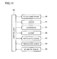
- a control unit 50 illustrated in Fig. 11 exercises control over the entire refrigerator/freezer 1: the control includes operation control of the refrigeration cycle and power supply control to the heater 31.
- the control unit 50 is connected to the ice-releasing device 24, the heater 31, a compressor 51 constituting the refrigeration cycle, a blower 52 for sending cold air to each portion inside the refrigerator/freezer, a water supply device 53 for supplying water to the ice-making device 10, a temperature sensor 54, an ice amount sensor 55 disposed in the ice-making chamber 4.
- the temperature sensor 54 is a generic term including temperature measuring elements such as a thermistor disposed at where it is necessitated, including the thermistor 25.
- the control unit 50 controls power supply to the heater 31 by the following three steps.
- the three steps include "normal heating”, “preheating” having a smaller heat value than the "normal heating”, and “rapid heating” having a larger heat value than the "normal heating”. For instance, power consumption of the "normal heating” is set to 5 to 6 W, power consumption of the "preheating” is set to 2 W, and power consumption of the "rapid heating” is set to 7 to 8 W, so that there is a difference between the heat values.
- the flow of Fig. 12 starts when the ice-making tray 20 restores its right-side-up posture after the ice-releasing operation.
- Step #101 the control unit 50 operates the water supply device 53 to supply water to the ice-making tray 20.
- temperature of the ice-making chamber 4 is near freezing temperature (being set to minus 18 degrees Celsius)
- temperature of the ice-making tray 20 rises when the water is supplied.
- the thermistor 25 detects the temperature rise in Step #102.
- Step #103 Because the water is cooled as soon as it is supplied, the temperature measured by the thermistor 25 temporarily rises and then starts to drop. Then, the process proceeds to Step #103.
- Step #103 is a freezing preparation step.
- the control unit 50 supplies the heater 31 with power for "preheating", and makes water temperature drop at a predetermined rate.
- heating by the heater 31 is performed.
- transparent ice cubes can be grown not from a part contacting with the inner surface of the ice-making tray 20 but from a part away from the inner surface of the ice-making tray 20. Therefore, ice cubes having high transparency can be easily grown.
- Step #103 If the compressor 51 enters a stop period during Step #103, the temperature drop is naturally decelerated.
- the control unit 50 stops power supply to the heater 31 so as to avoid wasteful power consumption.
- the control unit 50 also stops power supply to the heater 31 if the temperature measured by the thermistor 25 is a predetermined value or higher, namely, 1 degrees Celsius or higher, for example. In this way, it is avoided to waste power supplied to the heater 31 when there is no possibility that water is frozen from a part contacting with the ice-making tray 20.
- Step #104 the control unit 50 checks whether the temperature measured by the thermistor 25 has dropped down below freezing point or not. If the temperature has dropped down below freezing point, the process proceeds to Step #105.
- Step #105 is an ice melting step.
- the control unit 50 supplies power for the "rapid heating" to the heater 31 for a predetermined period to heat the ice-making tray 20. Even if there is a delay in proceeding from Step #104 to Step #105 because of a measurement error of the thermistor 25 so that an ice cube is adhered to the inner surface of the ice-making cell 21, the ice cube is melted in this stage. Therefore, it is possible to proceed to Step #106 without generating residual ice fraction that hampers making of uniformly transparent ice cubes.
- the control unit 50 supplies power for the "rapid heating" to the heater 31 in Step #105 regardless of the compressor 51 is operating or stopped. In this way, melting of ice can be proceeded rapidly.
- Step #106 is a freezing proceeding step.
- the control unit 50 supplies power for the "normal heating" to the heater 31 until the temperature measured by the thermistor 25 has dropped to a predetermined temperature.
- the control unit 50 stops power supply to the heater 31 if the compressor 51 enters the stop period during Step #106, so as to avoid wasteful power consumption.
- the inner surface of the ice-making tray 20 may be already frozen when operation of the compressor 51 is resumed. Therefore, after resuming the operation of the compressor 51, the heater 31 is supplied with power for "rapid heating" for a predetermined period so as to melt ice possibly existing on the inner surface of the ice-making tray 20. In this way, transparent ice cubes can be produced continuously despite of intermittent power supply to the heater 31.
- Step #107 the control unit 50 checks whether the temperature measured by the thermistor 25 has dropped to a predetermined temperature or not. If the temperature measured by the thermistor 25 has dropped to a predetermined temperature, namely minus 9 degrees Celsius for example, it is determined that making of ice cubes is completed, and the process proceeds to Step #108.
- the control unit 50 stops power supply to the heater 31 in Step #108. When a predetermined period has elapsed, it is determined that transparent ice cubes have securely produced, and the process proceeds to Step #109.
- Step #109 the control unit 50 controls the ice-releasing device 24 to turn over the ice-making tray 20.
- the protrusion 48 abuts a stopper (not shown) formed on the ice-making tray casing 12. Because the ice-releasing device 24 continues to turn the ice-making tray 20 by a predetermined angle after that, the ice-making tray 20 is twisted and deformed.
- the gap 47 As described above, between the wind shield plate 45 and the cover 34, there is disposed the gap 47 such that they do not contact with each other when the ice-making tray 20 is twisted. Therefore, the rim of the cover 34 and the wind shield plate 45 do not rub each other and no creak or abrasion is caused between them.
- the ice-making tray 20 When the ice-making tray 20 is twisted, ice cubes in the ice-making cells 21 are extruded and drop into an ice container (not shown) placed in the ice-making chamber 4. After releasing of ice cubes, the ice-releasing device 24 turns the ice-making tray 20 in the opposite direction so as to restore the original posture of the ice-making tray 20. In this way, one cycle of the ice making operation is finished. If the ice amount sensor 55 indicates that the amount of ice cube in the ice container is not sufficient, the ice-making operation of the next cycle is started in succession. If the ice amount sensor 55 indicates that there is sufficient amount of ice cube in the ice container, the ice-making device 10 enter an idle period.
- Step #108' the control unit 50 gradually decreases current supplied to the heater 31 until stopping the power supply, instead of stopping the power supply to the heater 31 promptly after the temperature measured by the thermistor 25 has dropped to a predetermined temperature.
- Temperatures of all the ice-making cells 21 are not necessarily identical to the temperature measured by the thermistor 25. Even when the temperature measured by the thermistor 25 has dropped to the predetermined temperature, temperatures of some ice-making cells 21 have not dropped that low yet, and unfrozen water may still remain. It is possible to prevent the water from remaining unfrozen by the process of gradually decreasing the supplied current until stopping the power supply instead of stopping the power supply to the heater 31 promptly after the temperature measured by the thermistor 25 has dropped to a predetermined temperature.
- the control unit 50 also operates as follows.
- the control unit 50 sets the current supplied to the heater 31 to a low level.
- default set temperature is set to minus 18 degrees Celsius. If the temperature is higher than minus 18 degrees Celsius, the current supplied to the heater 31 is set to a low level. If the temperature is minus 18 degrees Celsius or lower, the current supplied to the heater 31 is set to a normal level.
- the heater 31 is supplied with power of a calorific value necessary for controlling the progress of freezing so that the ice making process can be optimized.
- control unit 50 reduces rotational frequency of the compressor 51 and rotational frequency of the blower 52.
- the cold chamber temperature is set to a relatively high temperature when the outdoor temperature is low, operation time of the compressor 51 is usually shortened, and a period of time while the ice-making tray 20 is exposed to the cold air is decreased so that the ice-making time is prolonged.
- the operation time of the compressor 51 is prolonged so that the ice making time can be shortened.
- a feature of the present invention is in a structure of the cold air discharge port 13.
- the cold air discharge port 13 is divided into two parts, namely an upper part and a lower part.
- the upper part is a distal discharge port 13a directed toward a distal portion of the ice-making tray 20 in a view from the cold air discharge port 13.
- the lower part is a proximal discharge port 13b directed toward a proximal portion of the ice-making tray 20 in a view from the cold air discharge port 13.
- An amount of discharge flow from the distal discharge port 13a is set to be smaller than an amount of discharge flow from the proximal discharge port 13b. This can be realized by setting the proximal discharge port 13b larger than the distal discharge port 13a, for example.
- the distal discharge port 13a and the proximal discharge port 13b are disposed in this way, the cold air is not concentrated on a particular ice-making cell 21 of the ice-making tray 20, and hence the freezing can be proceeded uniformly in every ice-making cell 21.
- the proximal discharge port 13b exists, only the portion of the ice-making tray 20 close to the cold air discharge port is heavily cooled to cause a large temperature difference with the portion of the ice-making tray 20 distant from the cold air discharge port.
- the distal discharge port 13a exists, the cold air having small airflow amount from the distal discharge port 13a helps to cool the distant part as an auxiliary cold air.
- temperature variation among the ice-making cells 21 can be suppressed, and the freezing proceeds uniformly in every ice-making cell 21.
- freezing speed can be easily controlled by the heater 31 so that transparency of the ice cubes can be improved.
- the cold air discharge port 13 is divided into two parts of upper and lower, but the number of division is not limited to this. It is possible to adopt a larger number of division. In addition, it is possible to adopt another structure in which the cold air discharge port 13 is divided not into upper and lower but into left and right, and the left part is used as the distal discharge port while the right part is used as the proximal discharge port, for example.
- the present invention can be widely applied to an ice-making device for refrigerator/freezer.
Landscapes
- Engineering & Computer Science (AREA)
- Physics & Mathematics (AREA)
- Mechanical Engineering (AREA)
- Thermal Sciences (AREA)
- General Engineering & Computer Science (AREA)
- Chemical & Material Sciences (AREA)
- Combustion & Propulsion (AREA)
- Production, Working, Storing, Or Distribution Of Ice (AREA)
- Devices That Are Associated With Refrigeration Equipment (AREA)
Abstract
Description
- The present invention relates to an ice-making device for refrigerator/freezer.
- A refrigerator/freezer is usually equipped with an ice-making device for making ice cubes utilizing cold air for freezing. Examples of the ice-making device disposed in the refrigerator/freezer are shown in
Patent Documents 1 to 6. - Ice cubes produced by the ice-making device for refrigerator/freezer usually have low transparency. Therefore, inventions have been made for improving transparency of ice cubes. The ice-making devices described in
Patent Documents 1 to 6 also include such inventions. - The ice-making devices described in
Patent Documents - The ice-making devices described in
Patent Documents 4 to 6 have structures in which transparent ice cubes and cloudy ice cubes are produced in a combined state, and the transparent ice cubes and the cloudy ice cubes are severed from each other when the ice cubes are released from the ice-making tray, and the cloudy ice cubes are left in the ice-making tray while only the transparent ice cubes are released. -
- Patent Document 1:
JP-A-4-260768 - Patent Document 2:
JP-A-5-196331 1 - Patent Document 3:
JP-A-1-203869 - Patent Document 4:
JP-A-2007-232336 - Patent Document 5:
JP-A-2008-151504 - Patent Document 6:
JP-A-2008-157619 - It is an object of the present invention to provide a novel mechanism for producing transparent ice cubes in an ice-making device for refrigerator/freezer.
- In order to achieve the above-mentioned object, the present invention is characterized as follows: an ice-making device for refrigerator/freezer comprises an ice-making chamber, an ice-making tray disposed in the ice-making chamber for making an ice cube by cold air blown into the ice-making chamber, a thermistor for measuring temperature in the ice-making tray, a heater for heating the ice-making tray from below, and a control unit for exercising operation control of refrigeration cycle and control of power supply to the heater on the basis of the temperature measured by the thermistor as determination criterion. The control unit controls progress of freezing by supplying power to the heater after supplying water to the ice-making tray, and a cold air discharge port of the ice-making chamber includes a distal discharge port directed toward a distal portion of the ice-making tray in a view from the cold air discharge port, and a proximal discharge port directed toward a proximal portion of the ice-making tray in a view from the cold air discharge port.
- According to a preferred embodiment of the present invention, in the ice-making device for refrigerator/freezer having the above-mentioned structure, an amount of discharge flow from the distal discharge port is set to be smaller than an amount of discharge flow from the proximal discharge port.
- According to a preferred embodiment of the present invention, in the ice-making device for refrigerator/freezer having the above-mentioned structure, the heater is attached to and intimately contacts with an underside of the ice-making tray, and the underside of the ice-making tray is sheltered with a cover.
- According to a preferred embodiment of the present invention, in the ice-making device for refrigerator/freezer having the above-mentioned structure, a spring attachment rib is formed on the underside of the ice-making tray, the cover is provided with a through hole through which the spring attachment rib passes, and the cover is pressed to the heater by a pressure of a spring attached to the spring attachment rib passing through the through hole.
- According to a preferred embodiment of the present invention, in the ice-making device for refrigerator/freezer having the above-mentioned structure, the ice-making tray includes a support stud on a longitudinal-direction end thereof, and the cover shelters the underside of the ice-making tray in a state where a ring formed at an end of the cover engages with the support stud.
- According to a preferred embodiment of the present invention, in the ice-making device for refrigerator/freezer having the above-mentioned structure, the cover is provided with a through hole through which a boss formed on the underside of the ice-making tray is exposed, and a screw is screwed into the boss exposed from the through hole so that the cover is held in a movable manner along an axis of the boss.
- According to a preferred embodiment of the present invention, in the ice-making device for refrigerator/freezer having the above-mentioned structure, a top surface of the cover is provided with a rib for pressing the heater to the ice-making tray.
- According to a preferred embodiment of the present invention, in the ice-making device for refrigerator/freezer having the above-mentioned structure, each of longitudinal rims of the ice-making tray is provided with an wind shield plate for preventing cold air blown from above from proceeding to an underside of the ice-making tray.
- According to a preferred embodiment of the present invention, in the ice-making device for refrigerator/freezer having the above-mentioned structure, the wind shield plate has a notch formed from an edge thereof.
- According to a preferred embodiment of the present invention, in the ice-making device for refrigerator/freezer having the above-mentioned structure, a cover attached to the underside of the ice-making tray shelters the heater, and a gap is formed between a rim of the cover and the opposing wind shield plate so as not to cause a contact therebetween when the ice-making tray is twisted for releasing of ice cubes.
- According to the present invention, because the water in the ice-making tray is frozen while being heated by the heater from below, a major core part of the produced ice cube becomes transparent though the surface thereof becomes uneven as a trace of bubbles discharged from the periphery. In addition, because freezing proceeds uniformly in every part of the ice-making tray, it is easy to control the freezing speed by controlling the heater so that transparency of the ice cube can be improved.
-
-
Fig. 1 is a front view of a refrigerator/freezer equipped with an ice-making device. -
Fig. 2 is a partial vertical cross-sectional view of the refrigerator/freezer illustrating the ice-making device. -
Fig. 3 is a vertical cross-sectional view of the ice-making device taken along the direction perpendicular toFig. 2 . -
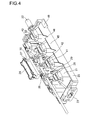
Fig. 4 is a perspective view of the ice-making tray in an upside down state and a thermistor to be combined thereto. -
Fig. 5 is a perspective view of the ice-making tray in an upside down state, and a heater and a cover to be combined thereto. -
Fig. 6 is a perspective view of the ice-making tray in an upside down state to which the cover for the heater is attached. -
Fig. 7 is a side view of a spring. -
Fig. 8 is a plan view of the cover. -
Fig. 9 is a partial plan view of the heater. -
Fig. 10 is a cross-sectional view of the heater. -
Fig. 11 is a control block diagram of the refrigerator/freezer. -
Fig. 12 is a flowchart illustrating an operation of the ice-making device. -
Fig. 13 is a flowchart illustrating another operation of the ice-making device. - A refrigerator/
freezer 1 illustrated inFig. 1 has a structure in which acold chamber 2 withdouble doors making chamber 4 with a door 5 and a freezing chamber 6 with adoor 7 are disposed thereunder, a drawertype freezing chamber 8 is disposed thereunder, and a drawertype vegetable chamber 9 is disposed in the lowermost part. A refrigeration cycle (not shown) including a compressor and a heat exchanger generates cold air, which is distributed to each chamber through ducts, and hence cold storage temperature or freezing temperature necessary in each chamber is obtained. This mechanism is well known and is not described here in detail. - As illustrated in
Fig. 2 andFig. 3 , an ice-makingdevice 10 is disposed in a ceiling part of the ice-makingchamber 4. A structure thereof is described below with reference to the drawings ofFig. 4 to Fig. 10 . -
Fig. 2 is a cross-sectional view of the ice-makingdevice 10 viewed from the left side of the refrigerator/freezer 1. On a wall behind the ice-makingchamber 4, there is formed aduct 11 blowing cold air into the ice-making chamber 4. An ice-makingtray casing 12 extends to the front from an upper end of theduct 11. An opening is formed in the underside of the ice-makingtray casing 12 so that ice cubes produced in an ice-making tray can be dropped therethrough. Theduct 11 is provided with a coldair discharge port 13 facing toward the inside of the ice-makingtray casing 12. - An ice-making
tray 20 is disposed inside the ice-makingtray casing 12 at a position for receiving the cold air blown from the coldair discharge port 13. The ice-makingtray 20 is molded with synthetic resin that does not lose elasticity at low temperature. If bubbles in supplied water adhere to the inner surface of the ice-makingtray 20, it is difficult to produce transparent ice cubes. Therefore, as means for preventing bubbles from adhering to the ice-makingtray 20, it is preferable to use polypropylene mixed with silicone as molding material for the ice-makingtray 20 or to coat the ice-makingtray 20 with fluorocarbon resin after molding. - Fine particles attracted by static electricity generated on the surface of the ice-making
tray 20 also become obstacles to production of transparent ice cubes. Therefore, it is preferable to mold the ice-makingtray 20 with a material that hardly generate static electricity, such as resin mixed with silicone or resin in which an antistatic agent is kneaded and mixed, or to apply an antistatic agent onto the ice-makingtray 20 after molding. - The ice-making
tray 20 includes a total of eight ice-makingcells 21 for producing ice cubes having a trapezoidal cross section. The eight ice-makingcells 21 are arranged in two columns and four rows, and therefore the ice-makingtray 20 has an elongated shape in a plan view. This elongated ice-makingtray 20 is placed so that the longitudinal direction thereof coincides with the front-rear direction of the refrigerator/freezer 1. - A
support stud 22 is formed on a longitudinal-direction end of the ice-makingtray 20, and asocket 23 is formed on an opposing end of the ice-making tray. Thesupport stud 22 is supported in a rotatable manner by the ice-makingtray casing 12. Thesocket 23 is connected to a shaft of an ice-releasing device 24 (seeFig. 3 ) disposed inside the ice-makingtray casing 12 and is supported by the ice-releasingdevice 24. Thesupport stud 22 and thesocket 23 are disposed on the same horizontal axis. The ice-releasingdevice 24 includes a motor and a reduction gear which give the ice-makingtray 20 rotation of a certain angle about the horizontal axis. - On an underside of the ice-making
tray 20, there is disposed athermistor 25 at a position between two rows of the ice-makingcells 21. Thethermistor 25 measures temperature inside the ice-makingcell 21 through a wall of the ice-makingcell 21. - The
thermistor 25 is fixed by athermistor cover 26.Pins 27 protrude from four corners of thethermistor cover 26 in the direction perpendicular to the longitudinal direction of the ice-makingtray 20. A total of fourlegs 28 protrude from the underside of the ice-makingtray 20 so as to surround thethermistor 25. A horizontal throughhole 29 for thepin 27 to pass through theleg 28 is formed on the tip of theleg 28. Athermistor protection sealer 30 is placed on thethermistor 25, thethermistor cover 26 is placed thereon, and thepin 27 is engaged in the horizontal throughhole 29 of theleg 28, so that thethermistor 25 is fixed. - On the underside of the ice-making
tray 20, aheater 31 illustrated inFig. 5 is disposed in addition to thethermistor 25. Theheater 31 is formed by coating a heater wire with silicone resin, and an entirety thereof is flexible so as to conform to a twist of the ice-makingtray 20.Parallel ribs 32 for receiving theheater 31 are formed on a top of each ice-makingcell 21 in an upside down state. - The
parallel ribs 32 include two ribs disposed in parallel at a predetermined interval, and the interval between the ribs is determined so that theheater 31 is received between the ribs in a loose fit manner. The interval between the ribs is determined in this way for a purpose that theheater 31 can move freely to a certain extent when the ice-makingtray 20 is twisted. - The
heater 31 is laid so as to form a symmetric shape in the left and right with respect to the longitudinal center line of the ice-makingtray 20. In the embodiment, an outline of theheater 31 is substantially a U-shape. A pair ofpower supply lines 33 is connected to open ends of the U-shape. - Being designed to generate a small amount of heat, the
heater 31 has a structure in which very thin heater wire is wound around a glass fiber core. Therefore, if theheater 31 is twisted in a direction in which the winding is tightened, the heater wire may easily be severed. Therefore, as described above, theheater 31 can move freely to a certain extent, and the layout of theheater 31 is shaped such that an excessive force is not applied to the heater wire as much as possible. - After the
heater 31 is housed between theparallel ribs 32 so as to contact intimately with the underside of the ice-makingtray 20, the underside of the ice-makingtray 20 is sheltered with acover 34. Thecover 34 prevents the cold air from entering into an underside space of the ice-makingtray 20 and makes temperature distribution among the ice-makingcells 21 become uniform. In addition, thecover 34 plays a role of keeping theheater 31 between theparallel ribs 32. - The
cover 34 has a rectangular tray shape, and aring 35 for thesupport stud 22 to pass through is formed at one end thereof. After thering 35 is engaged with thesupport stud 22, thecover 34 is attached to the ice-makingtray 20 with twoscrews 36 and onespring 37. The attachment of thecover 34 is not a firm one restricting movement of the ice-makingtray 20 but a flexible one not hampering twist of the ice-makingtray 20 when ice cubes are released. It is preferable to mold thecover 34 with synthetic resin that does not lose elasticity at low temperature, similarly to the ice-makingtray 20. - Two through
holes 38 are formed near both ends in the longitudinal direction of thecover 34. In addition, two throughholes 39 are formed symmetrically with respect to the longitudinal center line at a position closer to the center of thecover 34 than the through holes 38. The throughhole 38 has a circular shape and aboss 40 having a circular cross-section shape formed on the underside of the ice-makingtray 20 passes through the throughhole 38. The throughhole 39 has a rectangular shape and aspring attachment rib 41 formed on the underside of the ice-makingtray 20 passes through the throughhole 39. - After the
screws 36 are screwed and fixed to thebosses 40 exposed from the throughholes 38, thecover 34 is held in a movable manner along the axes of thebosses 40 with thescrews 36 as drop-off stoppers. In other words, thescrews 36 do not fasten thecover 34 but prevent thecover 34 from disengaging from the ice-makingtray 20. - When the
cover 34 is prevented from disengaging by thescrews 36, thespring attachment ribs 41 protrude from the throughholes 39 of thecover 34 as illustrated inFig. 6 . Attachment hooks 43 on both ends of thespring 37 are engaged with horizontal throughholes 42 formed on the tips of thespring attachment ribs 41. Thespring 37 is made by bending and forming a spring steel wire in a shape having the attachment hooks 43 in the middle in the longitudinal direction andhairpin portions 44 at both ends in the longitudinal direction. - The
hairpin portion 44 extends at a downward slant inFig. 6 , namely in the direction of the ice-makingtray 20. As illustrated inFig. 7 , thehairpin portions 44 are lower than the attachment hooks 43 in thespring 37, and a linear portion connecting thehairpin portions 44 is horizontal. Therefore, if the attachment hooks 43 are engaged with the horizontal throughholes 42 of thespring attachment rib 41, thehairpin portions 44 and the linear portion connecting thehairpin portions 44 exert pressure on thecover 34. Thecover 34 is pressed to theheater 31 as illustrated inFig. 3 , and hence theheater 31 is held by a constant load so as not to disengage from theparallel ribs 32. In this way, theheater 31 intimately contacts with the ice-makingcell 21 so that heat of theheater 31 can be efficiently conducted to the ice-makingcell 21. - As illustrated in
Fig. 8 ,ribs 34a for pressing theheater 31 to the ice-makingtray 20 are formed along the shape of theheater 31 and on the top surface of thecover 34. Thanks to theribs 34a, contact area between theheater 31 and thecover 34 can be reduced so that sliding between theheater 31 and thecover 34, which is inevitably generated when the ice-makingtray 20 is twisted, becomes smooth. In addition, strength of thecover 34 is enhanced by theribs 34a. - On the top surface of the
cover 34, there is also formed alateral rib 34b connecting theribs 34a. A position of therib 34b corresponds to a position at which thespring 37 presses thecover 34. Therefore, pressure from thespring 37 can be transmitted uniformly to theheater 31. Therib 34b is also useful for reinforcement of thecover 34. - On a side of the
heater 31 facing thecover 34, there is formed a low-lyingrib 31a illustrated inFig. 9 and Fig. 10 . Therib 31a is useful for distinguishing whether theheater 31 is disposed in a twisted state or not. - On each of longitudinal rims of the ice-making
tray 20, there is integrally formed awind shield plate 45 extending downward. Thewind shield plate 45 prevents the cold air blown from above to the ice-makingtray 20 from proceeding to a lower portion of the ice-makingtray 20. Therefore, it is possible to reduce loss of heating effect of theheater 31 caused by the cold air having entered into the underside space of the ice-makingtray 20, and let the cold air concentrate on the top of the ice-makingtray 20. - In the
wind shield plate 45, there are formednotches 46 vertically from the edge at positions corresponding to boundaries between the ice-makingcells 21. In the embodiment, there are twonotches 46 in awind shield plate 45. If thenotches 46 are not formed, when the ice-makingtray 20 is twisted, a stress inside thewind shield plate 45 is concentrated at one part, and hence resin material at the part is whitened at an early stage and a crack may open there. By the existence of thenotches 46, the stress inside thewind shield plate 45 is dispersed and occurrence of whitening or a crack can be prevented. - As illustrated in
Fig. 3 , between thewind shield plate 45 and thecover 34, there is formedgaps 47 for preventing contact between them when the ice-makingtray 20 is twisted for releasing of ice cubes. - In the end of the ice-making
tray 20 on thesupport stud 22 side, there is formed aprotrusion 48 on a side thereof. Theprotrusion 48 is used for twisting the ice-makingtray 20 when the ice cubes are released. - A
control unit 50 illustrated inFig. 11 exercises control over the entire refrigerator/freezer 1: the control includes operation control of the refrigeration cycle and power supply control to theheater 31. Thecontrol unit 50 is connected to the ice-releasingdevice 24, theheater 31, acompressor 51 constituting the refrigeration cycle, ablower 52 for sending cold air to each portion inside the refrigerator/freezer, awater supply device 53 for supplying water to the ice-makingdevice 10, atemperature sensor 54, anice amount sensor 55 disposed in the ice-makingchamber 4. Thetemperature sensor 54 is a generic term including temperature measuring elements such as a thermistor disposed at where it is necessitated, including thethermistor 25. - The
control unit 50 controls power supply to theheater 31 by the following three steps. The three steps include "normal heating", "preheating" having a smaller heat value than the "normal heating", and "rapid heating" having a larger heat value than the "normal heating". For instance, power consumption of the "normal heating" is set to 5 to 6 W, power consumption of the "preheating" is set to 2 W, and power consumption of the "rapid heating" is set to 7 to 8 W, so that there is a difference between the heat values. - Next, with reference to the flowchart of
Fig. 12 , an operation of the ice-makingdevice 10 is described. The flow ofFig. 12 starts when the ice-makingtray 20 restores its right-side-up posture after the ice-releasing operation. - In
Step # 101, thecontrol unit 50 operates thewater supply device 53 to supply water to the ice-makingtray 20. - Because the temperature of the ice-making
chamber 4 is near freezing temperature (being set to minus 18 degrees Celsius), temperature of the ice-makingtray 20 rises when the water is supplied. Thethermistor 25 detects the temperature rise inStep # 102. - Because the water is cooled as soon as it is supplied, the temperature measured by the
thermistor 25 temporarily rises and then starts to drop. Then, the process proceeds to Step #103. -
Step # 103 is a freezing preparation step. Thecontrol unit 50 supplies theheater 31 with power for "preheating", and makes water temperature drop at a predetermined rate. - Also in the following steps heating by the
heater 31 is performed. By freezing the ice-makingtray 20 while heating from below by theheater 31, transparent ice cubes can be grown not from a part contacting with the inner surface of the ice-makingtray 20 but from a part away from the inner surface of the ice-makingtray 20. Therefore, ice cubes having high transparency can be easily grown. - If the
compressor 51 enters a stop period duringStep # 103, the temperature drop is naturally decelerated. Thecontrol unit 50 stops power supply to theheater 31 so as to avoid wasteful power consumption. - The
control unit 50 also stops power supply to theheater 31 if the temperature measured by thethermistor 25 is a predetermined value or higher, namely, 1 degrees Celsius or higher, for example. In this way, it is avoided to waste power supplied to theheater 31 when there is no possibility that water is frozen from a part contacting with the ice-makingtray 20. - In
Step # 104, thecontrol unit 50 checks whether the temperature measured by thethermistor 25 has dropped down below freezing point or not. If the temperature has dropped down below freezing point, the process proceeds to Step #105. -
Step # 105 is an ice melting step. Thecontrol unit 50 supplies power for the "rapid heating" to theheater 31 for a predetermined period to heat the ice-makingtray 20. Even if there is a delay in proceeding fromStep # 104 to Step #105 because of a measurement error of thethermistor 25 so that an ice cube is adhered to the inner surface of the ice-makingcell 21, the ice cube is melted in this stage. Therefore, it is possible to proceed to Step #106 without generating residual ice fraction that hampers making of uniformly transparent ice cubes. - The
control unit 50 supplies power for the "rapid heating" to theheater 31 inStep # 105 regardless of thecompressor 51 is operating or stopped. In this way, melting of ice can be proceeded rapidly. -
Step # 106 is a freezing proceeding step. Thecontrol unit 50 supplies power for the "normal heating" to theheater 31 until the temperature measured by thethermistor 25 has dropped to a predetermined temperature. - The
control unit 50 stops power supply to theheater 31 if thecompressor 51 enters the stop period duringStep # 106, so as to avoid wasteful power consumption. However, because of the stop of power supply to theheater 31, the inner surface of the ice-makingtray 20 may be already frozen when operation of thecompressor 51 is resumed. Therefore, after resuming the operation of thecompressor 51, theheater 31 is supplied with power for "rapid heating" for a predetermined period so as to melt ice possibly existing on the inner surface of the ice-makingtray 20. In this way, transparent ice cubes can be produced continuously despite of intermittent power supply to theheater 31. - In
Step # 107, thecontrol unit 50 checks whether the temperature measured by thethermistor 25 has dropped to a predetermined temperature or not. If the temperature measured by thethermistor 25 has dropped to a predetermined temperature, namely minus 9 degrees Celsius for example, it is determined that making of ice cubes is completed, and the process proceeds to Step #108. - The
control unit 50 stops power supply to theheater 31 inStep # 108. When a predetermined period has elapsed, it is determined that transparent ice cubes have securely produced, and the process proceeds to Step #109. - In
Step # 109, thecontrol unit 50 controls the ice-releasingdevice 24 to turn over the ice-makingtray 20. As the ice-releasingdevice 24 is turning the ice-makingtray 20 about thesupport stud 22, a little before the upside-down turn is completed, theprotrusion 48 abuts a stopper (not shown) formed on the ice-makingtray casing 12. Because the ice-releasingdevice 24 continues to turn the ice-makingtray 20 by a predetermined angle after that, the ice-makingtray 20 is twisted and deformed. As described above, between thewind shield plate 45 and thecover 34, there is disposed thegap 47 such that they do not contact with each other when the ice-makingtray 20 is twisted. Therefore, the rim of thecover 34 and thewind shield plate 45 do not rub each other and no creak or abrasion is caused between them. - When the ice-making
tray 20 is twisted, ice cubes in the ice-makingcells 21 are extruded and drop into an ice container (not shown) placed in the ice-makingchamber 4. After releasing of ice cubes, the ice-releasingdevice 24 turns the ice-makingtray 20 in the opposite direction so as to restore the original posture of the ice-makingtray 20. In this way, one cycle of the ice making operation is finished. If theice amount sensor 55 indicates that the amount of ice cube in the ice container is not sufficient, the ice-making operation of the next cycle is started in succession. If theice amount sensor 55 indicates that there is sufficient amount of ice cube in the ice container, the ice-makingdevice 10 enter an idle period. - It is possible to operate the ice-making
device 10 in accordance with the flowchart ofFig. 13 . In the flowchart ofFig. 13 , steps other than Step #108' are the same as those in the flowchart ofFig. 12 . In Step #108', thecontrol unit 50 gradually decreases current supplied to theheater 31 until stopping the power supply, instead of stopping the power supply to theheater 31 promptly after the temperature measured by thethermistor 25 has dropped to a predetermined temperature. - Temperatures of all the ice-making
cells 21 are not necessarily identical to the temperature measured by thethermistor 25. Even when the temperature measured by thethermistor 25 has dropped to the predetermined temperature, temperatures of some ice-makingcells 21 have not dropped that low yet, and unfrozen water may still remain. It is possible to prevent the water from remaining unfrozen by the process of gradually decreasing the supplied current until stopping the power supply instead of stopping the power supply to theheater 31 promptly after the temperature measured by thethermistor 25 has dropped to a predetermined temperature. - The
control unit 50 also operates as follows. - If the temperature in the ice-making
chamber 4 or the temperature of the cold air blown into the ice-makingchamber 4 is a predetermined value or higher, thecontrol unit 50 sets the current supplied to theheater 31 to a low level. As an example, default set temperature is set to minus 18 degrees Celsius. If the temperature is higher than minus 18 degrees Celsius, the current supplied to theheater 31 is set to a low level. If the temperature is minus 18 degrees Celsius or lower, the current supplied to theheater 31 is set to a normal level. - In this way, the
heater 31 is supplied with power of a calorific value necessary for controlling the progress of freezing so that the ice making process can be optimized. - If the cold chamber temperature is set to a relatively high temperature when the outdoor temperature is low, the
control unit 50 reduces rotational frequency of thecompressor 51 and rotational frequency of theblower 52. - If the cold chamber temperature is set to a relatively high temperature when the outdoor temperature is low, operation time of the
compressor 51 is usually shortened, and a period of time while the ice-makingtray 20 is exposed to the cold air is decreased so that the ice-making time is prolonged. By reducing both the rotational frequency of thecompressor 51 and the rotational frequency of theblower 52, the operation time of thecompressor 51 is prolonged so that the ice making time can be shortened. - A feature of the present invention is in a structure of the cold
air discharge port 13. As illustrated inFig. 2 , the coldair discharge port 13 is divided into two parts, namely an upper part and a lower part. The upper part is adistal discharge port 13a directed toward a distal portion of the ice-makingtray 20 in a view from the coldair discharge port 13. The lower part is aproximal discharge port 13b directed toward a proximal portion of the ice-makingtray 20 in a view from the coldair discharge port 13. - An amount of discharge flow from the
distal discharge port 13a is set to be smaller than an amount of discharge flow from theproximal discharge port 13b. This can be realized by setting theproximal discharge port 13b larger than thedistal discharge port 13a, for example. - Since the
distal discharge port 13a and theproximal discharge port 13b are disposed in this way, the cold air is not concentrated on a particular ice-makingcell 21 of the ice-makingtray 20, and hence the freezing can be proceeded uniformly in every ice-makingcell 21. - In addition, if only the
proximal discharge port 13b exists, only the portion of the ice-makingtray 20 close to the cold air discharge port is heavily cooled to cause a large temperature difference with the portion of the ice-makingtray 20 distant from the cold air discharge port. However, because thedistal discharge port 13a exists, the cold air having small airflow amount from thedistal discharge port 13a helps to cool the distant part as an auxiliary cold air. As a result, temperature variation among the ice-makingcells 21 can be suppressed, and the freezing proceeds uniformly in every ice-makingcell 21. Thus, freezing speed can be easily controlled by theheater 31 so that transparency of the ice cubes can be improved. - In this embodiment, the cold
air discharge port 13 is divided into two parts of upper and lower, but the number of division is not limited to this. It is possible to adopt a larger number of division. In addition, it is possible to adopt another structure in which the coldair discharge port 13 is divided not into upper and lower but into left and right, and the left part is used as the distal discharge port while the right part is used as the proximal discharge port, for example. - Although the embodiment of the present invention is described above, the scope of the present invention is not limited to this. The present invention can be embodied with various modifications within the scope thereof without deviating from the spirit of the present invention.
- The present invention can be widely applied to an ice-making device for refrigerator/freezer.
-
- 1 refrigerator/freezer
- 4 ice-making chamber
- 10 ice-making device
- 11 duct
- 13 cold air discharge port
- 13a distal discharge port
- 13b proximal discharge port
- 20 ice-making tray
- 21 ice-making cell
- 24 ice-releasing device
- 25 thermistor
- 31 heater
- 34 cover
- 36 screw
- 37 spring
- 38, 39 through hole
- 40 boss
- 41 spring attachment rib
- 45 wind shield plate
- 46 notch
- 50 control unit
- 51 compressor
- 52 blower
- 53 water supply device
Claims (10)
- An ice-making device for refrigerator/freezer comprising:an ice-making chamber;an ice-making tray disposed in the ice-making chamber for making an ice cube by cold air blown into the ice-making chamber;a thermistor for measuring temperature in the ice-making tray;a heater for heating the ice-making tray from below; anda control unit for exercising operation control of refrigeration cycle and control of power supply to the heater on the basis of the temperature measured by the thermistor as determination criterion, whereinthe control unit controls progress of freezing by supplying power to the heater after supplying water to the ice-making tray, anda cold air discharge port of the ice-making chamber includes a distal discharge port directed toward a distal portion of the ice-making tray in a view from the cold air discharge port, and a proximal discharge port directed toward a proximal portion of the ice-making tray in a view from the cold air discharge port.
- The ice-making device for refrigerator/freezer according to claim 1, wherein an amount of discharge flow from the distal discharge port is set to be smaller than an amount of discharge flow from the proximal discharge port.
- The ice-making device for refrigerator/freezer according to claim 1, wherein the heater is attached to and intimately contacts with an underside of the ice-making tray, and the underside of the ice-making tray is sheltered with a cover.
- The ice-making device for refrigerator/freezer according to claim 3, wherein a spring attachment rib is formed on the underside of the ice-making tray, the cover is provided with a through hole through which the spring attachment rib passes, and the cover is pressed to the heater by a pressure of a spring attached to the spring attachment rib passing through the through hole.
- The ice-making device for refrigerator/freezer according to claim 3, wherein the ice-making tray includes a support stud on a longitudinal-direction end thereof, and the cover shelters the underside of the ice-making tray in a state where a ring formed at an end of the cover engages with the support stud.
- The ice-making device for refrigerator/freezer according to claim 3, wherein the cover is provided with a through hole through which a boss formed on the underside of the ice-making tray is exposed, and a screw is screwed into the boss exposed from the through hole so that the cover is held in a movable manner along an axis of the boss.
- The ice-making device for refrigerator/freezer according to claim 3, wherein a top surface of the cover is provided with a rib for pressing the heater to the ice-making tray.
- The ice-making device for refrigerator/freezer according to claim 1, wherein each of longitudinal rims of the ice-making tray is provided with an wind shield plate for preventing cold air blown from above from proceeding to an underside of the ice-making tray.
- The ice-making device for refrigerator/freezer according to claim 8, wherein the wind shield plate has a notch formed from an edge thereof.
- The ice-making device for refrigerator/freezer according to claim 8, wherein a cover attached to the underside of the ice-making tray shelters the heater, and a gap is formed between a rim of the cover and the opposing wind shield plate so as not to cause a contact therebetween when the ice-making tray is twisted for releasing of ice cubes.
Applications Claiming Priority (1)
| Application Number | Priority Date | Filing Date | Title |
|---|---|---|---|
| PCT/JP2011/056232 WO2012124075A1 (en) | 2011-03-16 | 2011-03-16 | Ice-making device for refrigerator/freezer |
Publications (2)
| Publication Number | Publication Date |
|---|---|
| EP2687795A1 true EP2687795A1 (en) | 2014-01-22 |
| EP2687795A4 EP2687795A4 (en) | 2014-11-05 |
Family
ID=46830204
Family Applications (1)
| Application Number | Title | Priority Date | Filing Date |
|---|---|---|---|
| EP11861126.8A Withdrawn EP2687795A4 (en) | 2011-03-16 | 2011-03-16 | Ice-making device for refrigerator/freezer |
Country Status (4)
| Country | Link |
|---|---|
| EP (1) | EP2687795A4 (en) |
| CN (1) | CN103429977B (en) |
| RU (1) | RU2013145311A (en) |
| WO (1) | WO2012124075A1 (en) |
Cited By (2)
| Publication number | Priority date | Publication date | Assignee | Title |
|---|---|---|---|---|
| US20210396444A1 (en) * | 2018-10-02 | 2021-12-23 | Lg Electronics Inc. | Refrigerator |
| US20210396441A1 (en) * | 2018-10-02 | 2021-12-23 | Lg Electronics Inc. | Refrigerator and method for controlling same |
Families Citing this family (10)
| Publication number | Priority date | Publication date | Assignee | Title |
|---|---|---|---|---|
| DE102012223628A1 (en) * | 2012-12-18 | 2014-06-18 | BSH Bosch und Siemens Hausgeräte GmbH | Refrigerating appliance with an ice maker temperature sensor |
| KR101798570B1 (en) * | 2016-04-08 | 2017-11-17 | 동부대우전자 주식회사 | Ice maker for refrigerator |
| AU2017409899B2 (en) * | 2017-04-19 | 2021-02-04 | Mitsubishi Electric Corporation | Ice maker |
| EP4549846A3 (en) * | 2018-10-02 | 2025-07-23 | LG Electronics Inc. | Refrigerator and method for controlling same |
| WO2020071774A1 (en) * | 2018-10-02 | 2020-04-09 | 엘지전자 주식회사 | Refrigerator |
| CN112789461B (en) * | 2018-10-02 | 2023-07-14 | Lg电子株式会社 | refrigerator |
| US12188705B2 (en) | 2018-10-02 | 2025-01-07 | Lg Electronics Inc. | Refrigerator and method for controlling the same |
| CN114838546B (en) | 2018-11-16 | 2023-12-29 | Lg电子株式会社 | Ice maker and refrigerator |
| KR102782080B1 (en) | 2019-03-22 | 2025-03-13 | 엘지전자 주식회사 | Ice maker and refrigerator |
| CN114623645A (en) * | 2020-12-14 | 2022-06-14 | 青岛海尔电冰箱有限公司 | Ice making control method, computer readable storage medium and refrigerator |
Family Cites Families (13)
| Publication number | Priority date | Publication date | Assignee | Title |
|---|---|---|---|---|
| JP2589731B2 (en) | 1988-02-08 | 1997-03-12 | 松下冷機株式会社 | Ice making equipment such as refrigerators |
| JPH0484086A (en) * | 1990-07-27 | 1992-03-17 | Hitachi Ltd | Ice making pan in refrigerator |
| JPH0772657B2 (en) | 1991-02-13 | 1995-08-02 | 株式会社東芝 | Automatic ice machine |
| JPH05196331A (en) | 1992-11-13 | 1993-08-06 | Toshiba Corp | Automatic ice machine |
| JP2003056966A (en) * | 2001-08-20 | 2003-02-26 | Fujitsu General Ltd | refrigerator |
| JP2008157619A (en) | 2003-03-24 | 2008-07-10 | Mitsubishi Electric Corp | Ice making equipment, refrigerator-freezer |
| JP3852609B2 (en) * | 2003-09-16 | 2006-12-06 | 三菱電機株式会社 | Ice making equipment, refrigerator |
| JP3807422B2 (en) * | 2004-08-03 | 2006-08-09 | 松下電器産業株式会社 | refrigerator |
| JP4480518B2 (en) * | 2004-08-24 | 2010-06-16 | シャープ株式会社 | Freezer refrigerator |
| JP4362124B2 (en) | 2006-03-03 | 2009-11-11 | 三菱電機株式会社 | refrigerator |
| JP4396767B2 (en) * | 2008-03-14 | 2010-01-13 | 三菱電機株式会社 | Freezer refrigerator |
| JP5142835B2 (en) * | 2008-06-06 | 2013-02-13 | 日立アプライアンス株式会社 | Ice making device and refrigerator provided with the ice making device |
| KR20100133155A (en) * | 2009-06-11 | 2010-12-21 | 엘지전자 주식회사 | Refrigerator with ice maker |
-
2011
- 2011-03-16 RU RU2013145311/13A patent/RU2013145311A/en not_active Application Discontinuation
- 2011-03-16 WO PCT/JP2011/056232 patent/WO2012124075A1/en not_active Ceased
- 2011-03-16 CN CN201180069293.3A patent/CN103429977B/en not_active Expired - Fee Related
- 2011-03-16 EP EP11861126.8A patent/EP2687795A4/en not_active Withdrawn
Cited By (4)
| Publication number | Priority date | Publication date | Assignee | Title |
|---|---|---|---|---|
| US20210396444A1 (en) * | 2018-10-02 | 2021-12-23 | Lg Electronics Inc. | Refrigerator |
| US20210396441A1 (en) * | 2018-10-02 | 2021-12-23 | Lg Electronics Inc. | Refrigerator and method for controlling same |
| US12013168B2 (en) * | 2018-10-02 | 2024-06-18 | Lg Electronics Inc. | Refrigerator and method for controlling same |
| US12326288B2 (en) * | 2018-10-02 | 2025-06-10 | Lg Electronics Inc. | Refrigerator |
Also Published As
| Publication number | Publication date |
|---|---|
| CN103429977B (en) | 2015-10-07 |
| RU2013145311A (en) | 2015-04-27 |
| WO2012124075A1 (en) | 2012-09-20 |
| EP2687795A4 (en) | 2014-11-05 |
| CN103429977A (en) | 2013-12-04 |
Similar Documents
| Publication | Publication Date | Title |
|---|---|---|
| EP2687795A1 (en) | Ice-making device for refrigerator/freezer | |
| JP2011064371A (en) | Ice-making device for refrigerator-freezer | |
| JP4680311B2 (en) | Refrigeration refrigerator ice making equipment | |
| JP5746584B2 (en) | Ice making apparatus and control method thereof | |
| JP5242740B2 (en) | Ice making device and refrigerator-freezer provided with the same | |
| KR102772207B1 (en) | Ice maker and Refrigerator having the same | |
| CN102506536B (en) | Air indirect cooling refrigerator and temperature control method thereof | |
| CA2761894C (en) | Refrigerator including ice making device | |
| CN103471310B (en) | Wind cooling refrigerator | |
| CN103486782B (en) | Refrigeration plant and defrosting control method thereof | |
| JP2013204882A (en) | Ice making device, refrigerator with the ice making device, and method of controlling the ice making device | |
| JP2011064374A (en) | Ice-making device for refrigerator-freezer | |
| KR20160148194A (en) | Ice manufacturing apparatus and method for refrigerator | |
| JP5618357B2 (en) | Refrigeration refrigerator ice making equipment | |
| CN203893534U (en) | Refrigerator | |
| CN102788465A (en) | Refrigerator | |
| CN102287971A (en) | Evaporator cover plate and refrigerator with same | |
| CN102927743A (en) | Air passage component and refrigerator with same | |
| CN101886867B (en) | Return air duct and refrigerator with same | |
| JP2011064372A (en) | Ice-making device for refrigerator-freezer | |
| CN204718245U (en) | Wind cooling refrigerator | |
| CN203719295U (en) | Air duct cover plate and air-cooled type refrigeration equipment | |
| CN203454531U (en) | Refrigeration chamber air duct used for refrigerator and refrigerator with same | |
| CN103438643B (en) | Refrigerating chamber air duct for refrigerator and refrigerator with same | |
| CN202598983U (en) | Refrigerator |
Legal Events
| Date | Code | Title | Description |
|---|---|---|---|
| PUAI | Public reference made under article 153(3) epc to a published international application that has entered the european phase |
Free format text: ORIGINAL CODE: 0009012 |
|
| 17P | Request for examination filed |
Effective date: 20131009 |
|
| AK | Designated contracting states |
Kind code of ref document: A1 Designated state(s): AL AT BE BG CH CY CZ DE DK EE ES FI FR GB GR HR HU IE IS IT LI LT LU LV MC MK MT NL NO PL PT RO RS SE SI SK SM TR |
|
| DAX | Request for extension of the european patent (deleted) | ||
| A4 | Supplementary search report drawn up and despatched |
Effective date: 20141007 |
|
| RIC1 | Information provided on ipc code assigned before grant |
Ipc: F25D 17/08 20060101AFI20140930BHEP Ipc: F25C 1/24 20060101ALI20140930BHEP |
|
| STAA | Information on the status of an ep patent application or granted ep patent |
Free format text: STATUS: THE APPLICATION IS DEEMED TO BE WITHDRAWN |
|
| 18D | Application deemed to be withdrawn |
Effective date: 20150505 |