EP2687787A2 - Oven - Google Patents
Oven Download PDFInfo
- Publication number
- EP2687787A2 EP2687787A2 EP13176928.3A EP13176928A EP2687787A2 EP 2687787 A2 EP2687787 A2 EP 2687787A2 EP 13176928 A EP13176928 A EP 13176928A EP 2687787 A2 EP2687787 A2 EP 2687787A2
- Authority
- EP
- European Patent Office
- Prior art keywords
- fluid
- housing
- cooling fan
- oven
- outlet
- Prior art date
- Legal status (The legal status is an assumption and is not a legal conclusion. Google has not performed a legal analysis and makes no representation as to the accuracy of the status listed.)
- Granted
Links
- 239000012530 fluid Substances 0.000 claims abstract description 151
- 238000010411 cooking Methods 0.000 claims abstract description 83
- 238000001816 cooling Methods 0.000 claims abstract description 46
- 238000004891 communication Methods 0.000 claims description 55
- 230000003247 decreasing effect Effects 0.000 claims description 6
- 238000007599 discharging Methods 0.000 abstract description 4
- 230000000694 effects Effects 0.000 description 5
- 238000000034 method Methods 0.000 description 4
- 230000008878 coupling Effects 0.000 description 3
- 238000010168 coupling process Methods 0.000 description 3
- 238000005859 coupling reaction Methods 0.000 description 3
- 230000015572 biosynthetic process Effects 0.000 description 2
- 238000001746 injection moulding Methods 0.000 description 2
- 239000012774 insulation material Substances 0.000 description 2
- 238000010438 heat treatment Methods 0.000 description 1
- 238000004519 manufacturing process Methods 0.000 description 1
- 238000005406 washing Methods 0.000 description 1
Images


Classifications
-
- F—MECHANICAL ENGINEERING; LIGHTING; HEATING; WEAPONS; BLASTING
- F24—HEATING; RANGES; VENTILATING
- F24C—DOMESTIC STOVES OR RANGES ; DETAILS OF DOMESTIC STOVES OR RANGES, OF GENERAL APPLICATION
- F24C15/00—Details
- F24C15/20—Removing cooking fumes
- F24C15/2007—Removing cooking fumes from oven cavities
-
- F—MECHANICAL ENGINEERING; LIGHTING; HEATING; WEAPONS; BLASTING
- F24—HEATING; RANGES; VENTILATING
- F24C—DOMESTIC STOVES OR RANGES ; DETAILS OF DOMESTIC STOVES OR RANGES, OF GENERAL APPLICATION
- F24C15/00—Details
- F24C15/32—Arrangements of ducts for hot gases, e.g. in or around baking ovens
-
- F—MECHANICAL ENGINEERING; LIGHTING; HEATING; WEAPONS; BLASTING
- F24—HEATING; RANGES; VENTILATING
- F24C—DOMESTIC STOVES OR RANGES ; DETAILS OF DOMESTIC STOVES OR RANGES, OF GENERAL APPLICATION
- F24C15/00—Details
- F24C15/006—Arrangements for circulation of cooling air
-
- F—MECHANICAL ENGINEERING; LIGHTING; HEATING; WEAPONS; BLASTING
- F24—HEATING; RANGES; VENTILATING
- F24C—DOMESTIC STOVES OR RANGES ; DETAILS OF DOMESTIC STOVES OR RANGES, OF GENERAL APPLICATION
- F24C15/00—Details
- F24C15/28—Draught shields
-
- F—MECHANICAL ENGINEERING; LIGHTING; HEATING; WEAPONS; BLASTING
- F24—HEATING; RANGES; VENTILATING
- F24C—DOMESTIC STOVES OR RANGES ; DETAILS OF DOMESTIC STOVES OR RANGES, OF GENERAL APPLICATION
- F24C15/00—Details
- F24C15/32—Arrangements of ducts for hot gases, e.g. in or around baking ovens
- F24C15/322—Arrangements of ducts for hot gases, e.g. in or around baking ovens with forced circulation
-
- F—MECHANICAL ENGINEERING; LIGHTING; HEATING; WEAPONS; BLASTING
- F24—HEATING; RANGES; VENTILATING
- F24C—DOMESTIC STOVES OR RANGES ; DETAILS OF DOMESTIC STOVES OR RANGES, OF GENERAL APPLICATION
- F24C7/00—Stoves or ranges heated by electric energy
-
- F—MECHANICAL ENGINEERING; LIGHTING; HEATING; WEAPONS; BLASTING
- F24—HEATING; RANGES; VENTILATING
- F24C—DOMESTIC STOVES OR RANGES ; DETAILS OF DOMESTIC STOVES OR RANGES, OF GENERAL APPLICATION
- F24C7/00—Stoves or ranges heated by electric energy
- F24C7/08—Arrangement or mounting of control or safety devices
- F24C7/082—Arrangement or mounting of control or safety devices on ranges, e.g. control panels, illumination
- F24C7/085—Arrangement or mounting of control or safety devices on ranges, e.g. control panels, illumination on baking ovens
Landscapes
- Engineering & Computer Science (AREA)
- Chemical & Material Sciences (AREA)
- Combustion & Propulsion (AREA)
- Mechanical Engineering (AREA)
- General Engineering & Computer Science (AREA)
- Electric Ovens (AREA)
- Baking, Grill, Roasting (AREA)
- Cookers (AREA)
Abstract
Description
- The present invention relates to an oven having a structure for discharging fluid from inside a cooking chamber.
- An oven is a machine designed to cook foodstuffs by use of a heating source, and includes a cooking chamber in which food is cooked and a machine chamber to accommodate electronic parts. In the process of cooking food, the inside of the cooking chamber is sealed to prevent heat from leaking to the outside.
- An oven is provided with an exhaust apparatus configured to exhaust fluid from the inside of the cooking chamber to adjust the internal pressure or humidity as a result of maintaining a high temperature in the cooking chamber, and to remove various gas or odour being generated during a process of cooking food.
- In a case of an exhaust apparatus having a structure capable of exhausting fluid of the inside of the cooking chamber by use of the Venturi effect, the amount of fluid being discharged through an outlet from the inside of the cooking chamber may significantly vary depending on the size and position of the outlet set to generate the Venturi effect.
- If the amount of fluid being discharged through the outlet significantly varies, for example, the amount of fluid being discharged through the outlet is excessively small, almost no exhaust effect is attained, and if the amount of fluid being discharged through the outlet is excessively large, the cooking performance is degraded.
- Therefore, it is an aspect of the present disclosure to provide an oven having an improved exhaust structure capable of discharging a fluid from the inside of a cooking chamber at a constant rate.
- Additional aspects will be set forth in part in the description which follows and, in part, will be apparent from the description, or may be learned by practice of the disclosure.
- In accordance with one aspect, an oven includes a cooking chamber, a machine chamber, a cooling fan unit and a flow passage guide, also referred to as a fluid passage guide.
- The cooking chamber is for cooking food. The machine chamber may be disposed at an upper side of the cooking chamber and accommodating an electronic component. The cooling fan unit may be disposed at an inside of the machine chamber to cool the machine chamber. The flow passage guide may communicate with an inside of the cooking chamber and an inside of the cooling fan unit such that a fluid of the inside of the cooking chamber is introduced to the inside of the cooling fan unit. The cooling fan unit may include a cooling fan, a first outlet, a second outlet, and a flow control hole. The cooling fan may be configured to suck a fluid of the inside the machine chamber and blow the fluid. The first outlet may allow the fluid blown by the cooling fan to be discharged to an outside the cooling fan unit therethrough. The second outlet may allow a fluid passing through the fluid passage guide to be discharged to the inside of the cooling fan unit therethrough. The flow control hole may control a volume of the fluid discharged through the second outlet, by guiding the fluid of the inside of the cooling fan unit so as to be introduced to the fluid passage guide.
- The fluid passage guide may include a first terminal, a second terminal and a third terminal. The first terminal may communicate with the cooking chamber. The second terminal may communicate with the second outlet. The third terminal may communicate with the flow control hole.
- The flow passage guide may include a first flow passage, a third flow passage and a second flow passage. The first flow passage may allow a fluid introduced through the first terminal to flow there along. The third flow passage may allow a fluid introduced through the third terminal to flow there along. The second flow passage may allow a fluid introduced from the third flow passage to flow while joining a fluid introduced from the first flow passage there along.
- The cooling fan unit may include an inclined surface formed by having at least one portion thereof inclined. The second outlet may be provided at one side of the inclined surface.
- The second outlet may be formed by slitting one portion of the inclined surface.
- The fluid being discharged through the second outlet may be discharged to the outside the cooling fan unit through the first outlet together with a fluid which is being introduced to the cooling fan unit by being blown by the cooling fan.
- In accordance with one aspect, an oven may include a cooking chamber, a machine chamber, a housing, a cooling fan, a fluid passage guide and a plurality of communication holes. The cooking chamber may cook food. The machine chamber may accommodate an electronic component. The housing may be disposed an inside the machine chamber. The cooling fan may be coupled to one end of the housing to suck a fluid of an outside the housing and blow the sucked fluid to an inside of the housing. The fluid passage guide may be coupled to the cooking chamber and the housing. The plurality of communication holes may be formed through one surface of the housing such that the housing communicates with the fluid passage guide in at least two different positions. The plurality of communication holes may include a first communication hole and a second communication hole. The first communication hole may guide a fluid of an inside of the flow passage guide so as to be discharged to an inside of the housing. The second communication hole may guide a fluid of the inside of the housing so as to be introduced to the inside of the flow passage guide.
- At least one outlet may be provided at other end of the housing to guide the fluid being introduced to the inside of the housing so as to be discharged to the outside the housing.
- The housing may include a width decrease part and a parallel part. The width decrease part may have a width decreased in an upper and lower side direction. The parallel part may have a width maintained constant in an upper and lower side direction and may be provided at one end thereof with the outlet.
- The first communication hole may be provided at the parallel part.
- The second communication hole may be provided at the width decrease part.
- The first communication hole may be formed by slitting one portion of the housing. The flow passage guide may include a first flow passage, a third flow passage and a second flow passage. The first flow passage may allow a fluid introduced from the cooking chamber to flow there along. The third flow passage may allow a fluid introduced through the second communication hole to flow there along. The second flow passage may allow a fluid introduced from the third flow passage to flow while joining a fluid introduced from the first flow passage there along.
- The flow flowing along the third fluid passage, after being introduced to the inside of the housing through the first communication hole, is discharged to the outside the housing through the outlet together with the fluid of the inside of the housing.
- The outlet may be located between the cooking chamber and the machine chamber.
- These and/or other aspects will become apparent and more readily appreciated from the following description of the embodiments, taken in conjunction with the accompanying drawings in which:
-
FIG. 1 is a view illustrating an oven in accordance with an embodiment. -
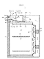
FIG. 2 is a side sectional view of an oven in accordance with an embodiment. -
FIG. 3 is a perspective view illustrating main components of a cooling fan unit. -
FIG. 4 is an exploded perspective view ofFIG. 3 . -
FIG. 5 is a view for explaining a principle of controlling the volume of a fluid being discharged through a second outlet. -
FIG. 6 is an exploded perspective view of a pop-up apparatus in accordance with an embodiment. -
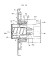
FIG. 7A is a cross sectional view of a pop-up apparatus in accordance with an embodiment, showing a knob disposed at a first position. -
FIG. 7B is a cross sectional view of a pop-up apparatus in accordance with an embodiment, showing a knob disposed at a second position. -
FIG. 8 is a perspective view of a knob of a pop-up apparatus in accordance with another embodiment. - Reference will now be made in detail to the embodiments, examples of which are illustrated in the accompanying drawings, wherein like reference numerals refer to like elements throughout.
-
FIG. 1 is a view illustrating an oven in accordance with an embodiment, andFIG. 2 is a side sectional view of an oven in accordance with an embodiment. - Referring to
FIGS. 1 and2 , theoven 1 includes anouter case 10 having a box shape, aninner case 11 accommodated in theouter case 10 and provided so as to be open at a front surface thereof, and adoor 12 opening and closing the open front surface of theinner case 11. - A
cooking chamber 20 cooking food is provided in theinner case 11.Guide rails 21 are provided at both sides of thecooking chamber 20, and arack 22, on which foodstuff or a vessel containing food is placed, is detachably coupled to theguide rail 21. Aheater 23 is installed at an upper side of thecooking chamber 20 to generate a heat for cooking the food on therack 22. Acirculation motor 24 and acirculation fan 25 are installed at a rear of thecooking chamber 20 to form uniform temperature at an inside thecooking chamber 20 by circulating the air of the inside of thecooking chamber 20 such that the food is rapidly cooked. A fan cover 26 formed of a plate-like member is coupled to a front side of thecirculation fan 25. A through-hole part 27 is formed at the fan cover 26. - A
machine chamber 30 in which various types of electronic components (not shown) are disposed is provided at an upper side of thecooking chamber 20. Buttons, adisplay part 34 and a pop-upapparatus 160 are provided at afront surface panel 33 forming themachine chamber 30 to adjust the cooking time or the cooking process. - A
cooking fan unit 100 is installed at an inside of themachine chamber 30 to cool the temperature of the inside of themachine chamber 30. The coolingfan unit 100 sucks the outside air to the inside of themachine chamber 30, and discharges the air toward a front of theoven 1. - The
cooking chamber 20 and thecooking fan unit 100 communicate with each other through afluid passage guide 150. In a process of cooking food, at least one portion of a fluid inside thecooking chamber 20 is introduced to the coolingfan unit 100 through thefluid passage guide 150, and then is discharged to the front of theoven 1. - A shielding
frame 41 is provided between thecooking chamber 20 and themachine chamber 30 to prevent an interior between thecooking chamber 20 and themachine chamber 30 from being exposed to the outside, and anheat insulation material 42 is located in a space among the upper side of thecooking chamber 20, the lower side of themachine chamber 30 and the shieldingframe 41. Theheat insulation material 42 blocks heat of the inside of thecooking chamber 20 from being transferred to the inside of themachine chamber 30. - Hereinafter, the structure of the cooling
fan unit 100 and a principle of discharging the fluid of the inside of thecooking chamber 20 will be described in detail. -
FIG. 3 is a perspective view illustrating main components of a cooling fan unit,FIG. 4 is an exploded perspective view ofFIG. 3 andFIG. 5 is a view for explaining a principle of controlling the volume of fluid being discharged through a second outlet. - Referring to
FIGS. 2 to 5 , the coolingfan unit 100 includes ahousing 110 disposed inside themachine chamber 30, and a coolingfan 120 coupled to one end of thehousing 110 to suck a fluid of an outside of thehousing 110 and blow the sucked fluid to the inside of thehousing 110. - The
housing 110 is composed by including anupper bracket 112 and alower bracket 114 coupled one on top of another to from a space in which a fluid flows. Theupper bracket 112 and thelower bracket 114 are inclined in directions facing each other. - A
first outlet 116 is formed at the other end of thehousing 110 opposite to the one end of the housing, to which the coolingfan 120 is coupled, to discharge the fluid being introduced to the inside of thehousing 110 to the outside of thehousing 110. Thefirst outlet 116 is located between thecooking chamber 20 and themachine chamber 30. - In addition, an
interior space 111 of thehousing 110 is composed by including awidth decrease part 111a having an interval in an upper and lower side direction decreased between theupper bracket 112 and thelower bracket 114, and aparallel part 111b having an interval maintained substantially constant in an upper and lower side direction between theupper bracket 112 and thelower bracket 114. Thefirst outlet 116 is formed at one end of theparallel part 111b. - The
width decrease part 111a serves to produce the Venturi effect at the inside of thehousing 110. The fluid being sucked to theinterior space 111 of thehousing 110 by the coolingfan 120 is gradually accelerated while passing through thewidth decrease part 111a, and then discharged to the outside of thehousing 110 through thefirst outlet 116. A plurality ofcommunication holes lower bracket 114. - The plurality of
communication holes first communication hole 131 guiding the fluid of an inside of afluid passage guide 150, which is described later, so as to be discharged to theinterior space 111 of thehousing 110, and asecond communication hole 132 guiding the fluid flowing in theinterior space 111 so as to be discharged to the inside of thefluid passage guide 150. Thefirst communication hole 131 is formed by slitting one portion of thelower bracket 114, and thesecond communication hole 132 is formed by perforating another portion of thelower bracket 114. In this case, oneportion 114a of thelower bracket 114 bent to an inner side of thehousing 110 by being slit to form thefirst communication hole 131 prevents the fluid of the inside of thehousing 110 from flowing backward and thus being introduced to the inside of thefluid passage guide 150. - The
first communication hole 131 may be formed at theparallel part 111b, and thesecond communication hole 132 may be formed at thewidth decrease part 111a. Since thefirst communication hole 131 is formed at theparallel part 111b, the volume of the fluid being discharged to theinterior space 111 of thehousing 110 through thefirst communication hole 131 is maintained within a predetermined range. That is, in a case in which thefirst communication hole 131 is located at thewidth decrease part 111a, the volume of the fluid being discharged through thefirst communication hole 131 may be significantly affected depending on the interval between theupper bracket 112 and thelower bracket 114 of a portion having thefirst communication hole 131. However, in a case in which the interval between theupper bracket 112 and thelower bracket 114 of a portion having thefirst communication hole 131 is constant, the volume of the fluid being discharged through thefirst communication hole 131 is maintained within a predetermined range. - The
fluid passage guide 150 communicating the inside of thecooking chamber 20 and the inside of thehousing 110 is coupled to a lower surface of thelower bracket 114. Thefluid passage guide 150 includes afirst branch 151 passing through anupper frame 20a of thecooking chamber 20 and alower frame 30a of themachine chamber 30, asecond branch 152 connected to thefirst branch 151 and coupled to the lower surface of thelower bracket 114, and athird branch 153 connected to thesecond branch 152 and coupled to the lower surface of thelower bracket 114. - A
first terminal 151a communicating with the inside of thecooking chamber 20 is provided at one end of thefirst branch 151, and thefirst branch 151 is provided at an inside thereof with afirst fluid passage 151b along which a fluid being introduced through thefirst terminal 151a flows. Asecond terminal 152a communicating with thefirst communication hole 131 is provided at one end of thesecond branch 152, and thesecond branch 152 forms asecond fluid passage 152b, along which a fluid being introduced through thefirst fluid passage 151b and a fluid being introduced through thethird fluid passage 153b flow, in cooperation with the lower surface of thelower bracket 114. Athird terminal 153a communicating with thesecond communication hole 132 is provided at one end of thethird branch 153, and thethird branch 153 forms athird fluid passage 153b, along which a fluid being introduced through thesecond communication hole 132 flows, in cooperation with the lower surface of thelower bracket 114. - The
second terminal 152a communicating with thefirst communication hole 131 has a cross section smaller than a cross section of thefirst fluid passage 151b, and thesecond fluid passage 152b has a cross section decreased toward thesecond terminal 152a. - According to the shape of the
fluid passage guide 150, the Venturi effect occurs. The fluid being introduced to thefluid passage guide 150 from the inside of thecooking chamber 20 is gradually accelerated while passing through thefirst fluid passage 151b and thesecond fluid passage 152b, and discharged to theinterior space 111 of thehousing 110 through thefirst communication hole 131, and then discharged to the outside thehousing 110 through thefirst outlet 116. - Some of the fluid being introduced to the
interior space 111 of thehousing 110 by the coolingfan 120 is introduced to thethird fluid passage 153b through thesecond communication hole 132 and the third terminal 153a. The fluid being introduced to thethird fluid passage 153b is introduced to thesecond fluid passage 152b by a pressure drop occurring due to the flow of fluid passing through thesecond fluid passage 152b, is discharged to theinterior space 111 of thehousing 110 through thefirst communication hole 131 together with the fluid passing through thesecond fluid passage 152b, and then discharged to the outside of thehousing 110 through thefirst outlet 116. - The fluid of the inside of the
cooking chamber 20 being introduced through thefirst terminal 151a and the fluid of the inside of thehousing 110 being introduced through thesecond communication hole 132 and thethird terminal 153a are discharged to theinterior space 111 of thehousing 110 through thesecond terminal 152a. According to the equation of continuity of fluid, the sum of the volume of a fluid being introduced to thefirst terminal 151a among the fluid of the inside of thecooking chamber 20 and the volume of a fluid being introduced through thesecond communication hole 132 and the third terminal 153a among the fluid of the inside of thehousing 110 is equal to the volume of a fluid being discharged to theinterior space 111 of thehousing 110 through thesecond terminal 152a. In addition, the volume of the fluid being discharged to theinterior space 111 of thehousing 110 through thesecond terminal 152a is maintained constant. Accordingly, if the volume of a fluid being introduced through thesecond communication hole 132 and the third terminal 153a among the fluid of the inside thehousing 110 is increased, the volume of a fluid being introduced to thefirst terminal 151a among the fluid of thecooking chamber 20 is decreased. On the contrary, if the volume of a fluid being introduced through thesecond communication hole 132 and the third terminal 153a among the fluid of the inside thehousing 110 is decreased, the volume of a fluid being introduced to thefirst terminal 151a among the fluid of thecooking chamber 20 is increased. - By using such a principle, the volume of a fluid being discharged to the outside of the
cooking chamber 20 from the inside of thecooking chamber 20 is adjusted. That is, the volume of a fluid being discharged from the inside of thecooking chamber 20 to the outside of thecooking chamber 20 is equal to the volume of a fluid being introduced to thefirst terminal 151a among the fluid of the inside of thecooking chamber 10, and as described above, the volume of a fluid being introduced to thefirst terminal 151a among the fluid of the inside of thecooking chamber 20 varies with the volume of a fluid being introduced through thesecond communication hole 132 and the third terminal 153a. - Since the volume of the fluid being introduced through the
second communication hole 132 and the third terminal 153a substantially relates to a cross section of thesecond communication hole 132 or a formation position of thesecond communication hole 132 on thelower bracket 114, the volume of the fluid being discharged from the inside of thecooking chamber 20 to the outside of thecooking chamber 20 may be controlled by adjusting the cross section of thesecond communication hole 132 or the formation position of thesecond communication hole 132. In this regard, thesecond communication hole 132 may be regarded as a flow control hole. - As described above, the
flow control hole 132 is provided to control the volume of a fluid being discharged from the inside of thecooking chamber 20 to the outside of thecooking chamber 20, thereby forming the interior of thecooking chamber 20 having an optimum cooking environment. - Hereinafter, the pop-up
apparatus 160 provided at the front surface of theoven 1 will be described in detail. -
FIG. 6 is an exploded perspective view of a pop-up apparatus in accordance with an embodiment.FIG. 7A is a cross sectional view of a pop-up apparatus in accordance with an embodiment, showing a knob disposed at a first position.FIG. 7B is a cross sectional view of a pop-up apparatus in accordance with an embodiment, showing a knob disposed at a second position. The pop-up apparatus in accordance with the embodiment may be applied to various types of electronic products such as an oven, a washing machine and a refrigerator, and for the convenience of description, the following description will be made in relation to a pop-up apparatus applied to an oven as an example. - Referring to
FIGS. 1 ,6 ,7A and7B , the pop-upapparatus 160 includes aknob housing 161 installed at thefront surface panel 33 of theoven 1 and coupled to a rear surface of thefront surface panel 33, aknob 162 accommodated in theknob housing 161, aguide member 164 guiding a sliding movement of theknob 162, and anelastic member 163 disposed between theknob 162 and theguide member 164 to press theknob 162. - The
knob housing 161 includes acoupling part 161a coupled to the rear surface of thefront surface panel 33, aguide hole 161b formed through thecoupling part 161a and allowing theknob 162 to move to a front side of thefront surface panel 33, and a plurality ofcoupling bosses 161c extending to a rear side such that thecircuit board 166 is coupled thereto. - The
guide hole 161b includes at least onerestriction rib 171 protruding from an inner circumferential surface of theguide hole 161b. Therestriction rib 171 may be provided in one unit thereof formed in a ring shape along the inner circumferential surface of theguide hole 161b, or may be provided in plural units thereof disposed while being spaced apart from each other along the inner circumferential surface of theguide hole 161b. - The
restriction rib 171 restricts the tilting of theknob 162 accommodated in theknob housing 161. That is, in a case in which theknob 152 is tilted due to its own weight in a state of being accommodated in theknob housing 161, or tilted by being pressed by a link member (not shown) connecting theknob 152 to theguide member 164, therestriction rib 171 supports a side surface of theknob 162 in response to the tilting direction, thereby restricting the tilting of theknob 162. In addition, therestriction rib 171 prevents the inside of the pop-upapparatus 160 from being exposed through a gap G between theknob 162 and theguide hole 161b in a state that theknob 162 is accommodated in theknob housing 161, and enables the gap G between theknob 162 and theguide hole 161b to be constant in a circumferential direction of theknob 162, so that the external appearance of the product is improved while improving the reliability of the product. - In addition, the
guide hole 161b includes at least onelocking protrusion 173 protruding from the inner circumferential surface of theguide hole 161b. The lockingprotrusion 173 is disposed at a rear of therestriction rib 171, and makes contact with aflange part 162b of theknob 162, which is to be described later, to maintain theknob 162 at a first position in which theknob 162 protrudes to the front side of thefront surface panel 33 while restricting an axial direction movement of theknob 162. The locking protrusion 174 may be provided in one unit thereof formed in a ring shape along the inner circumferential surface of theguide hole 161b, or may be provided in plural units thereof disposed while being spaced apart from each other along the inner circumferential surface of theguide hole 161b. - The
knob 162 includes abody part 162a provided in a cylindrical shape having one side open, and aflange part 162b formed at one end of thebody part 162a. - The
body part 162a includes a crosssection enlargement part 172 having a cross section of at least one section thereof getting enlarged while nearing the front side of thefront surface panel 33 in a central axial direction C. Accordingly, when compared to a cross section of one end of thebody part 162a adjacent to theflange part 162b, a cross section of the other end of thebody part 162a protruding to the front side of thefront surface panel 33 by passing through thefront surface panel 33 is larger. - The cross
section enlargement part 172 serves to prevent the interior of the pop-upapparatus 160 from being exposed through the gab B between theknob 162 and theguide hole 161b in a state that theknob 162 is accommodated in theknob housing 161, in cooperation with therestriction rib 171, and maintain the gap G between theknob 162 and theguide hole 161b constant along the circumferential direction of theknob 162. - The
flange part 162b extends from one end of theknob 162 in a radial direction of theknob 162. Theflange part 162b makes contact with the lockingprotrusion 173 to maintain theknob 162 at the first position in which theknob 162 protrudes to the front side of thefront surface panel 33 while restricting the axial direction movement of theknob 162. Theflange part 162b and the lockingprotrusion 173 form astopper member 180. - A
rotary encoder 168 is coupled to a front surface of thecircuit board 166, and theguide member 164 is coupled to arotary shaft 168a of therotary encoder 168. Therotary encoder 168 detects the rotation direction, rotation speed, and rotation amount of theguide member 164 coupled to therotary shaft 168a, and converts the detected rotation direction, rotation speed, and rotation amount to electric signals. - The
guide member 164 is provided in a form of a cylinder having one end coupled to therotary shaft 168a of therotary encoder 168 and the other end provided in an open state. An outer circumferential surface of theguide member 164 makes contact with an inner circumferential surface of theknob 162 to guide the sliding movement of theknob 162, and if a rotating force is applied to theknob 152 in a state in which theknob 162 is disposed at the first position of protruding to the front side of thefront surface panel 33, theguide member 164 rotates together with theknob 162, thereby rotating therotary shaft 168a of therotary encoder 168. - The
elastic member 163 is provided between theknob 162 and theguide member 163. Theelastic member 163 is disposed in a space S formed between thebody part 162a of theknob 162 and theguide member 163 so as to be pressed, and serves to press theknob 162 to the front side. - The
knob 162 may be provided so as to be disposed at the first position of protruding to the front side of thefront surface panel 33 and a second position of being inserted to a rear side of thefront surface panel 33. In a state that theknob 162 is disposed at the second position, if a user presses a front surface of theknob 162, theknob 162 protrudes to the front side so as to be disposed at the first position, and in a state that theknob 162 is disposed at the first position, if a user presses the front surface of theknob 162 again, theknob 162 is inserted to the rear side of the front surfacedpanel 33 so as to be disposed at the second position. - The
stopper member 180 including theflange part 162b and the lockingprotrusion 173 restricts the movement of theknob 162 such that theknob 162 is disposed at the first position. In addition, theflange part 162b and the lockingprotrusion 173 make a surface contact with each other, thereby restricting the shake of theknob 162 in a state of theknob 162 being disposed at the first position. - The
restriction rib 171 restricts the tilting of theknob 162 in a state that theknob 162 is disposed at the second position. Therestriction rib 171 and the crosssection enlargement part 172 prevent the interior of the pop-upapparatus 160 from being exposed through the gap G between theknob 162 and theguide hole 161b in a state that theknob 162 is disposed at the second position, and enable the gap G between theknob 162 and theguide hole 161b to be constant in a circumferential direction of theknob 162, so that the external appearance of the product is improved while improving the reliability of the product. -
FIG. 8 is a perspective view of a knob of a pop-up apparatus in accordance with another embodiment. - Referring to
FIG. 8 , aknob 262 in accordance with another embodiment includes afirst portion 271 including a crosssection enlargement part 275 and asecond portion 272 including aflange part 262b. - The
first portion 271 and thesecond portion 272 are coupled so as to be separated from each other. A plurality ofhooks 272a protruding from one surface of theflange part 262b facing thefirst portion 271 are formed at one end of thesecond portion 272, and a plurality ofhook holes 271a are formed at one end of thefirst portion 271 such that the plurality ofhooks 272a are insertedly fixed to the plurality ofhook holes 271a. - Since the
knob 262 is composed of thefirst portion 271 provided so as to be separated from thesecond portion 272, theknob 262 is manufactured through an injection molding for the productivity. In a case in which thefirst portion 271 is not separated from thesecond portion 272, the crosssection enlargement part 275 causes an inverse gradient in a direction opposite to a direction in which theknob 262 is pulled from a mold after being completed with curing in the mold, thereby having a difficulty of an operator in separating theknob 262 from the mold. In order to remove such a constraint, thefirst portion 271 and thesecond portion 272 are manufactured from different molds, respectively, and coupled to each other, thereby manufacturing theknob 262 including the crosssection enlargement part 275 and theflange part 262b through an injection molding while improving the productivity. - As is apparent from the above description, the embodiments can control the volume of a fluid being discharged from the inside of the cooking chamber, so that the environment of the inside of the cooking chamber is maintained in a constant state at all times.
- Although a few embodiments have been shown and described, it would be appreciated by those skilled in the art that changes may be made in these embodiments without departing from the principles of the invention, the scope of which is defined in the claims.
Claims (15)
- An oven comprising:a cooking chamber for cooking food;a machine chamber for accommodating electronic components;a cooling fan unit disposed inside the machine chamber to cool the machine chamber; anda fluid passage guide communicating between the inside of the cooking chamber and the inside of the cooling fan unit such that fluid inside the cooking chamber is introduced to the inside of the cooling fan unit,wherein the cooling fan unit comprises:a cooling fan configured to suck fluid inside the machine chamber and blow the fluid;a first outlet for allowing the fluid blown by the cooling fan to be discharged outside the cooling fan unit;a second outlet for allowing a fluid passing through the fluid passage guide to be discharged to the inside of the cooling fan unit; anda flow control hole for controlling a volume of the fluid discharged through the second outlet, by guiding the fluid inside the cooling fan unit to be introduced to the fluid passage guide.
- The oven of claim 1, wherein the fluid passage guide comprises:a first terminal communicating with the cooking chamber;a second terminal communicating with the second outlet; anda third terminal communicating with the flow control hole.
- The oven of claim 2, wherein the fluid passage guide comprises:a first flow passage in which a fluid introduced through the first terminal flows;a third flow passage in which a fluid introduced through the third terminal flows; anda second flow passage in which a fluid introduced from the third flow passage flows while joining the fluid introduced from the first flow passage.
- The oven of claim 1, wherein:the cooling fan unit comprises an inclined surface formed by having at least one portion thereof inclined, andthe second outlet is provided at one side of the inclined surface.
- The oven of claim 4, wherein the second outlet is formed by slitting one portion of the inclined surface.
- The oven of claim 1, wherein the fluid being discharged through the second outlet is discharged to the outside the cooling fan unit through the first outlet together with a fluid, which is being introduced to the cooling fan unit by being blown by the cooling fan.
- An oven comprising:a cooking chamber for cooking food;a machine chamber accommodating electronic components;a housing disposed inside the machine chamber;a cooling fan coupled to one end of the housing to suck fluid from outside the housing and blow the sucked fluid to an inside of the housing;a fluid passage guide coupled to the cooking chamber and the housing; anda plurality of communication holes formed through one surface of the housing such that the housing communicates with the fluid passage guide in at least two different positions,wherein the plurality of communication holes comprise:a first communication hole guiding a fluid of an inside of the fluid passage guide so as to be discharged to an inside of the housing; anda second communication hole guiding a fluid of the inside of the housing so as to be introduced to the inside of the fluid passage guide.
- The oven of claim 7, wherein at least one outlet is provided at other end of the housing to guide the fluid being introduced to the inside of the housing so as to be discharged to the outside of the housing.
- The oven of claim 8, wherein the housing comprises:a width decrease part having a width decreased in an upper and lower side direction; anda parallel part having a width maintained constant in an upper and lower side direction and provided at one end thereof with the outlet.
- The oven of claim 9, wherein the first communication hole is provided at the parallel part.
- The oven of claim 9, wherein the second communication hole is provided at the width decrease part.
- The oven of claim 7, wherein the first communication hole is formed by slitting one portion of the housing.
- The oven of any one of claims 7 to 12, wherein the fluid passage guide comprises:a first flow passage along which a fluid introduced from the cooking chamber flows;a third flow passage along which a fluid introduced through the second communication hole flows;a second flow passage along which a fluid introduced from the third flow passage flows while joining a fluid introduced from the first flow passage.
- The oven of claim 13, wherein the flow flowing along the third flow passage, after being introduced to the inside of the housing through the first communication hole, is discharged together with the fluid of the inside of the housing to the outside the housing through the outlet.
- The oven of any one of claims 7 to 14, wherein the outlet is located between the cooking chamber and the machine chamber.
Applications Claiming Priority (1)
| Application Number | Priority Date | Filing Date | Title |
|---|---|---|---|
| KR1020120079450A KR101931366B1 (en) | 2012-07-20 | 2012-07-20 | Oven |
Publications (3)
| Publication Number | Publication Date |
|---|---|
| EP2687787A2 true EP2687787A2 (en) | 2014-01-22 |
| EP2687787A3 EP2687787A3 (en) | 2015-01-21 |
| EP2687787B1 EP2687787B1 (en) | 2017-08-30 |
Family
ID=48832772
Family Applications (1)
| Application Number | Title | Priority Date | Filing Date |
|---|---|---|---|
| EP13176928.3A Active EP2687787B1 (en) | 2012-07-20 | 2013-07-17 | Oven |
Country Status (4)
| Country | Link |
|---|---|
| US (1) | US9551493B2 (en) |
| EP (1) | EP2687787B1 (en) |
| KR (1) | KR101931366B1 (en) |
| CN (1) | CN103720374A (en) |
Cited By (10)
| Publication number | Priority date | Publication date | Assignee | Title |
|---|---|---|---|---|
| EP2930435A1 (en) * | 2014-04-08 | 2015-10-14 | Indesit Company S.p.A. | Household cooking appliance |
| EP2980489A1 (en) * | 2014-07-30 | 2016-02-03 | Elica S.p.A. | Device for cooling the handle of an oven |
| US9357787B2 (en) | 2013-06-27 | 2016-06-07 | Middleby Marshall Holdings Llc | Forced moisture evacuation for rapid baking |
| WO2016105955A3 (en) * | 2014-12-23 | 2016-09-01 | Middleby Marshall Holdings LLC d/b/a NUVU Food Service Systems | Forced moisture evacuation for rapid baking or cooking |
| EP3438552A4 (en) * | 2016-06-03 | 2019-05-08 | Samsung Electronics Co., Ltd. | Oven |
| CN110944549A (en) * | 2017-05-25 | 2020-03-31 | 三星电子株式会社 | Steam cooking device |
| US10694753B2 (en) | 2013-05-23 | 2020-06-30 | Duke Manufacturing Co. | Food preparation apparatus and methods |
| WO2021001559A1 (en) * | 2019-07-04 | 2021-01-07 | Electrolux Appliances Aktiebolag | Cooking oven with oven cavity and cooling channel |
| US10918112B2 (en) | 2013-05-23 | 2021-02-16 | Duke Manufacturing Co. | Dough preparation apparatus and methods |
| US11149962B2 (en) | 2017-05-25 | 2021-10-19 | Samsung Electronics Co., Ltd. | Steam cooker |
Families Citing this family (6)
| Publication number | Priority date | Publication date | Assignee | Title |
|---|---|---|---|---|
| EP2532971A1 (en) * | 2011-06-07 | 2012-12-12 | Koninklijke Philips Electronics N.V. | Apparatus for preparing food |
| JP6378351B2 (en) * | 2014-03-18 | 2018-08-22 | コーニンクレッカ フィリップス エヌ ヴェKoninklijke Philips N.V. | Equipment for food preparation with improved thermal protection |
| KR102291276B1 (en) * | 2014-12-19 | 2021-08-20 | 삼성전자주식회사 | Oven |
| JP6537885B2 (en) * | 2015-05-18 | 2019-07-03 | 象印マホービン株式会社 | Cooker |
| CN106123055A (en) * | 2016-06-27 | 2016-11-16 | 广东美的厨房电器制造有限公司 | For heating the control equipment of utensil, method and heating utensil |
| JP6550671B1 (en) * | 2018-10-26 | 2019-07-31 | 日本たばこ産業株式会社 | Atomization unit and non-combustion suction device |
Family Cites Families (14)
| Publication number | Priority date | Publication date | Assignee | Title |
|---|---|---|---|---|
| DE2309873A1 (en) * | 1973-02-28 | 1974-08-29 | Burger Eisenwerke Ag | PROCEDURE FOR SELF-CLEANING THE INSIDE OF A FRYING OR OVEN |
| US4601279A (en) * | 1984-07-10 | 1986-07-22 | Societe De Dietrich | Pyrolytic self-cleaning domestic oven with improved means for protecting electronic panel and controls from heat damages |
| FR2688297B1 (en) * | 1992-03-03 | 1999-07-30 | Europ Equip Menager | ELECTRIC HOUSEHOLD COOKING APPARATUS, IN PARTICULAR OVENS OR COOKERS COMPRISING A DEPRESSION DEVICE. |
| DE4211755A1 (en) * | 1992-04-08 | 1993-10-14 | Licentia Gmbh | Electric cooking oven - has cooling air and steam extraction system in spiral housing contg. fan |
| FR2789480B1 (en) * | 1999-02-09 | 2001-05-04 | Cepem | PYROLYSIS OVEN USING A SOIL CRACKING CELL |
| DE10060155A1 (en) * | 2000-12-04 | 2002-06-20 | Bsh Bosch Siemens Hausgeraete | Cooking appliance |
| DE10240145B4 (en) * | 2002-08-30 | 2011-07-14 | BSH Bosch und Siemens Hausgeräte GmbH, 81739 | Cooking appliance and duct device |
| FR2902501B1 (en) * | 2006-06-15 | 2009-11-27 | Brandt Ind | COOKING OVEN WITH STEAM |
| FR2906872B1 (en) * | 2006-10-05 | 2015-05-08 | Brandt Ind | COOKING OVEN COMPRISING AN AIR DEFLECTION DEVICE. |
| US7468496B2 (en) * | 2006-11-15 | 2008-12-23 | Electrolux Home Products, Inc. | Dynamic flow oven cavity vent |
| SI22689A (en) * | 2007-12-17 | 2009-06-30 | Gorenje Gospodinjski Aparati, D.D. | Integrated oven with forced ventilation |
| EP2519776B8 (en) * | 2009-12-31 | 2017-06-28 | Arçelik Anonim Sirketi | Oven with a ventilating duct |
| ITTO20100712A1 (en) * | 2010-08-25 | 2012-02-26 | Indesit Co Spa | COOKING OVEN, PARTICULARLY FOR HOUSEHOLD USE, OF IMPROVED TYPE |
| ITTO20110191A1 (en) * | 2011-03-03 | 2012-09-04 | Indesit Co Spa | COOKING OVEN, PARTICULARLY FOR HOUSEHOLD USE |
-
2012
- 2012-07-20 KR KR1020120079450A patent/KR101931366B1/en active IP Right Grant
-
2013
- 2013-07-17 EP EP13176928.3A patent/EP2687787B1/en active Active
- 2013-07-19 US US13/946,342 patent/US9551493B2/en active Active
- 2013-07-22 CN CN201310498556.3A patent/CN103720374A/en active Pending
Non-Patent Citations (1)
| Title |
|---|
| None |
Cited By (16)
| Publication number | Priority date | Publication date | Assignee | Title |
|---|---|---|---|---|
| US10694753B2 (en) | 2013-05-23 | 2020-06-30 | Duke Manufacturing Co. | Food preparation apparatus and methods |
| US11779023B2 (en) | 2013-05-23 | 2023-10-10 | Duke Manufacturing Co. | Dough preparation apparatus and methods |
| US11602149B2 (en) | 2013-05-23 | 2023-03-14 | Duke Manufacturing Co. | Food preparation apparatus and methods |
| US10918112B2 (en) | 2013-05-23 | 2021-02-16 | Duke Manufacturing Co. | Dough preparation apparatus and methods |
| US9936706B2 (en) | 2013-06-27 | 2018-04-10 | Middleby Marshall Holding Llc | Forced moisture evacuation for rapid baking |
| US9357787B2 (en) | 2013-06-27 | 2016-06-07 | Middleby Marshall Holdings Llc | Forced moisture evacuation for rapid baking |
| EP2930435A1 (en) * | 2014-04-08 | 2015-10-14 | Indesit Company S.p.A. | Household cooking appliance |
| EP2980489A1 (en) * | 2014-07-30 | 2016-02-03 | Elica S.p.A. | Device for cooling the handle of an oven |
| WO2016105955A3 (en) * | 2014-12-23 | 2016-09-01 | Middleby Marshall Holdings LLC d/b/a NUVU Food Service Systems | Forced moisture evacuation for rapid baking or cooking |
| EP3438552A4 (en) * | 2016-06-03 | 2019-05-08 | Samsung Electronics Co., Ltd. | Oven |
| US11067287B2 (en) | 2016-06-03 | 2021-07-20 | Samsung Electronics Co., Ltd. | Oven |
| CN110944549A (en) * | 2017-05-25 | 2020-03-31 | 三星电子株式会社 | Steam cooking device |
| EP3614888A4 (en) * | 2017-05-25 | 2020-05-06 | Samsung Electronics Co., Ltd. | Steam cooker |
| CN110944549B (en) * | 2017-05-25 | 2021-09-03 | 三星电子株式会社 | Steam cooking device |
| US11149962B2 (en) | 2017-05-25 | 2021-10-19 | Samsung Electronics Co., Ltd. | Steam cooker |
| WO2021001559A1 (en) * | 2019-07-04 | 2021-01-07 | Electrolux Appliances Aktiebolag | Cooking oven with oven cavity and cooling channel |
Also Published As
| Publication number | Publication date |
|---|---|
| US20140020670A1 (en) | 2014-01-23 |
| CN103720374A (en) | 2014-04-16 |
| EP2687787A3 (en) | 2015-01-21 |
| EP2687787B1 (en) | 2017-08-30 |
| KR20140012476A (en) | 2014-02-03 |
| US9551493B2 (en) | 2017-01-24 |
| KR101931366B1 (en) | 2018-12-21 |
Similar Documents
| Publication | Publication Date | Title |
|---|---|---|
| EP2687787B1 (en) | Oven | |
| KR102211731B1 (en) | Oven | |
| EP2857756A1 (en) | Oven | |
| CA2988718A1 (en) | Convection oven | |
| EP3309463B1 (en) | Oven | |
| KR20140129538A (en) | Cooking apparatus | |
| US9488377B2 (en) | Gas oven range | |
| KR102549151B1 (en) | Cooking Appliance | |
| KR20150141797A (en) | Oven | |
| KR20050019446A (en) | Microwave oven | |
| KR20170137488A (en) | Oven | |
| CN111263869A (en) | Baking oven | |
| EP1437922A1 (en) | Microwave oven | |
| JP4791983B2 (en) | Cooker | |
| US11849527B2 (en) | Oven appliance with improved convection cooking performance | |
| JP2015041505A (en) | Heating cooker | |
| KR101798579B1 (en) | Microwave oven | |
| KR100197705B1 (en) | Temperature detecting cover apparatus | |
| KR20120008105A (en) | A grease cover for microwave range | |
| JP2000039153A (en) | Heating cooker | |
| AU2005244394A2 (en) | System to convey air for convection or static ovens through cylinders and/or interstice and system of vertical opposed ventilation | |
| KR100518441B1 (en) | Fixing structure of PCB Bracket for Microwave oven | |
| KR100547694B1 (en) | Fixing structure of microwave duct | |
| KR100582296B1 (en) | Upper duct for Microwave oven | |
| KR20210095488A (en) | Cooking apparatus |
Legal Events
| Date | Code | Title | Description |
|---|---|---|---|
| PUAI | Public reference made under article 153(3) epc to a published international application that has entered the european phase |
Free format text: ORIGINAL CODE: 0009012 |
|
| AK | Designated contracting states |
Kind code of ref document: A2 Designated state(s): AL AT BE BG CH CY CZ DE DK EE ES FI FR GB GR HR HU IE IS IT LI LT LU LV MC MK MT NL NO PL PT RO RS SE SI SK SM TR |
|
| AX | Request for extension of the european patent |
Extension state: BA ME |
|
| PUAL | Search report despatched |
Free format text: ORIGINAL CODE: 0009013 |
|
| AK | Designated contracting states |
Kind code of ref document: A3 Designated state(s): AL AT BE BG CH CY CZ DE DK EE ES FI FR GB GR HR HU IE IS IT LI LT LU LV MC MK MT NL NO PL PT RO RS SE SI SK SM TR |
|
| AX | Request for extension of the european patent |
Extension state: BA ME |
|
| RIC1 | Information provided on ipc code assigned before grant |
Ipc: F24C 7/08 20060101ALI20141217BHEP Ipc: F24C 15/00 20060101ALI20141217BHEP Ipc: F24C 15/32 20060101AFI20141217BHEP Ipc: F24C 15/20 20060101ALI20141217BHEP |
|
| 17P | Request for examination filed |
Effective date: 20150721 |
|
| RBV | Designated contracting states (corrected) |
Designated state(s): AL AT BE BG CH CY CZ DE DK EE ES FI FR GB GR HR HU IE IS IT LI LT LU LV MC MK MT NL NO PL PT RO RS SE SI SK SM TR |
|
| 17Q | First examination report despatched |
Effective date: 20160307 |
|
| GRAP | Despatch of communication of intention to grant a patent |
Free format text: ORIGINAL CODE: EPIDOSNIGR1 |
|
| INTG | Intention to grant announced |
Effective date: 20161221 |
|
| GRAS | Grant fee paid |
Free format text: ORIGINAL CODE: EPIDOSNIGR3 |
|
| RAP1 | Party data changed (applicant data changed or rights of an application transferred) |
Owner name: SAMSUNG ELECTRONICS CO., LTD. |
|
| GRAA | (expected) grant |
Free format text: ORIGINAL CODE: 0009210 |
|
| AK | Designated contracting states |
Kind code of ref document: B1 Designated state(s): AL AT BE BG CH CY CZ DE DK EE ES FI FR GB GR HR HU IE IS IT LI LT LU LV MC MK MT NL NO PL PT RO RS SE SI SK SM TR |
|
| REG | Reference to a national code |
Ref country code: GB Ref legal event code: FG4D |
|
| REG | Reference to a national code |
Ref country code: CH Ref legal event code: EP |
|
| REG | Reference to a national code |
Ref country code: AT Ref legal event code: REF Ref document number: 923922 Country of ref document: AT Kind code of ref document: T Effective date: 20170915 |
|
| REG | Reference to a national code |
Ref country code: IE Ref legal event code: FG4D |
|
| REG | Reference to a national code |
Ref country code: DE Ref legal event code: R096 Ref document number: 602013025709 Country of ref document: DE |
|
| REG | Reference to a national code |
Ref country code: NL Ref legal event code: MP Effective date: 20170830 |
|
| REG | Reference to a national code |
Ref country code: LT Ref legal event code: MG4D |
|
| REG | Reference to a national code |
Ref country code: AT Ref legal event code: MK05 Ref document number: 923922 Country of ref document: AT Kind code of ref document: T Effective date: 20170830 |
|
| PG25 | Lapsed in a contracting state [announced via postgrant information from national office to epo] |
Ref country code: SE Free format text: LAPSE BECAUSE OF FAILURE TO SUBMIT A TRANSLATION OF THE DESCRIPTION OR TO PAY THE FEE WITHIN THE PRESCRIBED TIME-LIMIT Effective date: 20170830 Ref country code: FI Free format text: LAPSE BECAUSE OF FAILURE TO SUBMIT A TRANSLATION OF THE DESCRIPTION OR TO PAY THE FEE WITHIN THE PRESCRIBED TIME-LIMIT Effective date: 20170830 Ref country code: HR Free format text: LAPSE BECAUSE OF FAILURE TO SUBMIT A TRANSLATION OF THE DESCRIPTION OR TO PAY THE FEE WITHIN THE PRESCRIBED TIME-LIMIT Effective date: 20170830 Ref country code: NO Free format text: LAPSE BECAUSE OF FAILURE TO SUBMIT A TRANSLATION OF THE DESCRIPTION OR TO PAY THE FEE WITHIN THE PRESCRIBED TIME-LIMIT Effective date: 20171130 Ref country code: AT Free format text: LAPSE BECAUSE OF FAILURE TO SUBMIT A TRANSLATION OF THE DESCRIPTION OR TO PAY THE FEE WITHIN THE PRESCRIBED TIME-LIMIT Effective date: 20170830 Ref country code: LT Free format text: LAPSE BECAUSE OF FAILURE TO SUBMIT A TRANSLATION OF THE DESCRIPTION OR TO PAY THE FEE WITHIN THE PRESCRIBED TIME-LIMIT Effective date: 20170830 |
|
| PG25 | Lapsed in a contracting state [announced via postgrant information from national office to epo] |
Ref country code: BG Free format text: LAPSE BECAUSE OF FAILURE TO SUBMIT A TRANSLATION OF THE DESCRIPTION OR TO PAY THE FEE WITHIN THE PRESCRIBED TIME-LIMIT Effective date: 20171130 Ref country code: GR Free format text: LAPSE BECAUSE OF FAILURE TO SUBMIT A TRANSLATION OF THE DESCRIPTION OR TO PAY THE FEE WITHIN THE PRESCRIBED TIME-LIMIT Effective date: 20171201 Ref country code: IS Free format text: LAPSE BECAUSE OF FAILURE TO SUBMIT A TRANSLATION OF THE DESCRIPTION OR TO PAY THE FEE WITHIN THE PRESCRIBED TIME-LIMIT Effective date: 20171230 Ref country code: RS Free format text: LAPSE BECAUSE OF FAILURE TO SUBMIT A TRANSLATION OF THE DESCRIPTION OR TO PAY THE FEE WITHIN THE PRESCRIBED TIME-LIMIT Effective date: 20170830 Ref country code: ES Free format text: LAPSE BECAUSE OF FAILURE TO SUBMIT A TRANSLATION OF THE DESCRIPTION OR TO PAY THE FEE WITHIN THE PRESCRIBED TIME-LIMIT Effective date: 20170830 Ref country code: LV Free format text: LAPSE BECAUSE OF FAILURE TO SUBMIT A TRANSLATION OF THE DESCRIPTION OR TO PAY THE FEE WITHIN THE PRESCRIBED TIME-LIMIT Effective date: 20170830 |
|
| PG25 | Lapsed in a contracting state [announced via postgrant information from national office to epo] |
Ref country code: NL Free format text: LAPSE BECAUSE OF FAILURE TO SUBMIT A TRANSLATION OF THE DESCRIPTION OR TO PAY THE FEE WITHIN THE PRESCRIBED TIME-LIMIT Effective date: 20170830 |
|
| PG25 | Lapsed in a contracting state [announced via postgrant information from national office to epo] |
Ref country code: CZ Free format text: LAPSE BECAUSE OF FAILURE TO SUBMIT A TRANSLATION OF THE DESCRIPTION OR TO PAY THE FEE WITHIN THE PRESCRIBED TIME-LIMIT Effective date: 20170830 Ref country code: RO Free format text: LAPSE BECAUSE OF FAILURE TO SUBMIT A TRANSLATION OF THE DESCRIPTION OR TO PAY THE FEE WITHIN THE PRESCRIBED TIME-LIMIT Effective date: 20170830 Ref country code: DK Free format text: LAPSE BECAUSE OF FAILURE TO SUBMIT A TRANSLATION OF THE DESCRIPTION OR TO PAY THE FEE WITHIN THE PRESCRIBED TIME-LIMIT Effective date: 20170830 Ref country code: PL Free format text: LAPSE BECAUSE OF FAILURE TO SUBMIT A TRANSLATION OF THE DESCRIPTION OR TO PAY THE FEE WITHIN THE PRESCRIBED TIME-LIMIT Effective date: 20170830 |
|
| PG25 | Lapsed in a contracting state [announced via postgrant information from national office to epo] |
Ref country code: EE Free format text: LAPSE BECAUSE OF FAILURE TO SUBMIT A TRANSLATION OF THE DESCRIPTION OR TO PAY THE FEE WITHIN THE PRESCRIBED TIME-LIMIT Effective date: 20170830 Ref country code: IT Free format text: LAPSE BECAUSE OF FAILURE TO SUBMIT A TRANSLATION OF THE DESCRIPTION OR TO PAY THE FEE WITHIN THE PRESCRIBED TIME-LIMIT Effective date: 20170830 Ref country code: SK Free format text: LAPSE BECAUSE OF FAILURE TO SUBMIT A TRANSLATION OF THE DESCRIPTION OR TO PAY THE FEE WITHIN THE PRESCRIBED TIME-LIMIT Effective date: 20170830 Ref country code: SM Free format text: LAPSE BECAUSE OF FAILURE TO SUBMIT A TRANSLATION OF THE DESCRIPTION OR TO PAY THE FEE WITHIN THE PRESCRIBED TIME-LIMIT Effective date: 20170830 |
|
| REG | Reference to a national code |
Ref country code: DE Ref legal event code: R097 Ref document number: 602013025709 Country of ref document: DE |
|
| REG | Reference to a national code |
Ref country code: FR Ref legal event code: PLFP Year of fee payment: 6 |
|
| PLBE | No opposition filed within time limit |
Free format text: ORIGINAL CODE: 0009261 |
|
| STAA | Information on the status of an ep patent application or granted ep patent |
Free format text: STATUS: NO OPPOSITION FILED WITHIN TIME LIMIT |
|
| 26N | No opposition filed |
Effective date: 20180531 |
|
| PG25 | Lapsed in a contracting state [announced via postgrant information from national office to epo] |
Ref country code: SI Free format text: LAPSE BECAUSE OF FAILURE TO SUBMIT A TRANSLATION OF THE DESCRIPTION OR TO PAY THE FEE WITHIN THE PRESCRIBED TIME-LIMIT Effective date: 20170830 |
|
| REG | Reference to a national code |
Ref country code: CH Ref legal event code: PL |
|
| PG25 | Lapsed in a contracting state [announced via postgrant information from national office to epo] |
Ref country code: MC Free format text: LAPSE BECAUSE OF FAILURE TO SUBMIT A TRANSLATION OF THE DESCRIPTION OR TO PAY THE FEE WITHIN THE PRESCRIBED TIME-LIMIT Effective date: 20170830 Ref country code: LU Free format text: LAPSE BECAUSE OF NON-PAYMENT OF DUE FEES Effective date: 20180717 |
|
| REG | Reference to a national code |
Ref country code: BE Ref legal event code: MM Effective date: 20180731 |
|
| REG | Reference to a national code |
Ref country code: IE Ref legal event code: MM4A |
|
| PG25 | Lapsed in a contracting state [announced via postgrant information from national office to epo] |
Ref country code: CH Free format text: LAPSE BECAUSE OF NON-PAYMENT OF DUE FEES Effective date: 20180731 Ref country code: IE Free format text: LAPSE BECAUSE OF NON-PAYMENT OF DUE FEES Effective date: 20180717 Ref country code: LI Free format text: LAPSE BECAUSE OF NON-PAYMENT OF DUE FEES Effective date: 20180731 |
|
| PG25 | Lapsed in a contracting state [announced via postgrant information from national office to epo] |
Ref country code: BE Free format text: LAPSE BECAUSE OF NON-PAYMENT OF DUE FEES Effective date: 20180731 |
|
| PG25 | Lapsed in a contracting state [announced via postgrant information from national office to epo] |
Ref country code: MT Free format text: LAPSE BECAUSE OF NON-PAYMENT OF DUE FEES Effective date: 20180717 |
|
| PG25 | Lapsed in a contracting state [announced via postgrant information from national office to epo] |
Ref country code: TR Free format text: LAPSE BECAUSE OF FAILURE TO SUBMIT A TRANSLATION OF THE DESCRIPTION OR TO PAY THE FEE WITHIN THE PRESCRIBED TIME-LIMIT Effective date: 20170830 |
|
| PG25 | Lapsed in a contracting state [announced via postgrant information from national office to epo] |
Ref country code: PT Free format text: LAPSE BECAUSE OF FAILURE TO SUBMIT A TRANSLATION OF THE DESCRIPTION OR TO PAY THE FEE WITHIN THE PRESCRIBED TIME-LIMIT Effective date: 20170830 Ref country code: HU Free format text: LAPSE BECAUSE OF FAILURE TO SUBMIT A TRANSLATION OF THE DESCRIPTION OR TO PAY THE FEE WITHIN THE PRESCRIBED TIME-LIMIT; INVALID AB INITIO Effective date: 20130717 |
|
| PG25 | Lapsed in a contracting state [announced via postgrant information from national office to epo] |
Ref country code: MK Free format text: LAPSE BECAUSE OF NON-PAYMENT OF DUE FEES Effective date: 20170830 Ref country code: CY Free format text: LAPSE BECAUSE OF FAILURE TO SUBMIT A TRANSLATION OF THE DESCRIPTION OR TO PAY THE FEE WITHIN THE PRESCRIBED TIME-LIMIT Effective date: 20170830 |
|
| PG25 | Lapsed in a contracting state [announced via postgrant information from national office to epo] |
Ref country code: AL Free format text: LAPSE BECAUSE OF FAILURE TO SUBMIT A TRANSLATION OF THE DESCRIPTION OR TO PAY THE FEE WITHIN THE PRESCRIBED TIME-LIMIT Effective date: 20170830 |
|
| PGFP | Annual fee paid to national office [announced via postgrant information from national office to epo] |
Ref country code: FR Payment date: 20220620 Year of fee payment: 10 |
|
| PGFP | Annual fee paid to national office [announced via postgrant information from national office to epo] |
Ref country code: GB Payment date: 20230620 Year of fee payment: 11 |
|
| PGFP | Annual fee paid to national office [announced via postgrant information from national office to epo] |
Ref country code: DE Payment date: 20230620 Year of fee payment: 11 |