EP2687731A1 - Device for securing an attachment section to a carrier with assembly check - Google Patents
Device for securing an attachment section to a carrier with assembly check Download PDFInfo
- Publication number
- EP2687731A1 EP2687731A1 EP13174336.1A EP13174336A EP2687731A1 EP 2687731 A1 EP2687731 A1 EP 2687731A1 EP 13174336 A EP13174336 A EP 13174336A EP 2687731 A1 EP2687731 A1 EP 2687731A1
- Authority
- EP
- European Patent Office
- Prior art keywords
- rotary shaft
- display element
- fastening
- assembly
- attachment
- Prior art date
- Legal status (The legal status is an assumption and is not a legal conclusion. Google has not performed a legal analysis and makes no representation as to the accuracy of the status listed.)
- Granted
Links
- 238000000034 method Methods 0.000 claims description 19
- 210000002105 tongue Anatomy 0.000 description 14
- 238000005452 bending Methods 0.000 description 4
- 238000003780 insertion Methods 0.000 description 2
- 230000037431 insertion Effects 0.000 description 2
- 230000003287 optical effect Effects 0.000 description 2
- 230000001154 acute effect Effects 0.000 description 1
- 230000001419 dependent effect Effects 0.000 description 1
- 239000004744 fabric Substances 0.000 description 1
- 210000003746 feather Anatomy 0.000 description 1
- 238000001746 injection moulding Methods 0.000 description 1
- 239000002184 metal Substances 0.000 description 1
- 239000007787 solid Substances 0.000 description 1
Images


Classifications
-
- F—MECHANICAL ENGINEERING; LIGHTING; HEATING; WEAPONS; BLASTING
- F16—ENGINEERING ELEMENTS AND UNITS; GENERAL MEASURES FOR PRODUCING AND MAINTAINING EFFECTIVE FUNCTIONING OF MACHINES OR INSTALLATIONS; THERMAL INSULATION IN GENERAL
- F16B—DEVICES FOR FASTENING OR SECURING CONSTRUCTIONAL ELEMENTS OR MACHINE PARTS TOGETHER, e.g. NAILS, BOLTS, CIRCLIPS, CLAMPS, CLIPS OR WEDGES; JOINTS OR JOINTING
- F16B21/00—Means for preventing relative axial movement of a pin, spigot, shaft or the like and a member surrounding it; Stud-and-socket releasable fastenings
- F16B21/06—Releasable fastening devices with snap-action
- F16B21/08—Releasable fastening devices with snap-action in which the stud, pin, or spigot has a resilient part
- F16B21/086—Releasable fastening devices with snap-action in which the stud, pin, or spigot has a resilient part the shank of the stud, pin or spigot having elevations, ribs, fins or prongs intended for deformation or tilting predominantly in a direction perpendicular to the direction of insertion
-
- F—MECHANICAL ENGINEERING; LIGHTING; HEATING; WEAPONS; BLASTING
- F16—ENGINEERING ELEMENTS AND UNITS; GENERAL MEASURES FOR PRODUCING AND MAINTAINING EFFECTIVE FUNCTIONING OF MACHINES OR INSTALLATIONS; THERMAL INSULATION IN GENERAL
- F16B—DEVICES FOR FASTENING OR SECURING CONSTRUCTIONAL ELEMENTS OR MACHINE PARTS TOGETHER, e.g. NAILS, BOLTS, CIRCLIPS, CLAMPS, CLIPS OR WEDGES; JOINTS OR JOINTING
- F16B2200/00—Constructional details of connections not covered for in other groups of this subclass
- F16B2200/95—Constructional details of connections not covered for in other groups of this subclass with markings, colours, indicators or the like
-
- F—MECHANICAL ENGINEERING; LIGHTING; HEATING; WEAPONS; BLASTING
- F16—ENGINEERING ELEMENTS AND UNITS; GENERAL MEASURES FOR PRODUCING AND MAINTAINING EFFECTIVE FUNCTIONING OF MACHINES OR INSTALLATIONS; THERMAL INSULATION IN GENERAL
- F16B—DEVICES FOR FASTENING OR SECURING CONSTRUCTIONAL ELEMENTS OR MACHINE PARTS TOGETHER, e.g. NAILS, BOLTS, CIRCLIPS, CLAMPS, CLIPS OR WEDGES; JOINTS OR JOINTING
- F16B5/00—Joining sheets or plates, e.g. panels, to one another or to strips or bars parallel to them
- F16B5/06—Joining sheets or plates, e.g. panels, to one another or to strips or bars parallel to them by means of clamps or clips
- F16B5/0607—Joining sheets or plates, e.g. panels, to one another or to strips or bars parallel to them by means of clamps or clips joining sheets or plates to each other
- F16B5/0621—Joining sheets or plates, e.g. panels, to one another or to strips or bars parallel to them by means of clamps or clips joining sheets or plates to each other in parallel relationship
- F16B5/0642—Joining sheets or plates, e.g. panels, to one another or to strips or bars parallel to them by means of clamps or clips joining sheets or plates to each other in parallel relationship the plates being arranged one on top of the other and in full close contact with each other
Definitions
- the invention relates to a device for attaching an attachment to a support member with assembly control according to the preamble of claim 1.
- Such a device is off EP 2 204 589 A1 known.
- the known device for attaching an attachment to a support member has a trained with a male and with a spreader as Sp Schwarzniet fastener having deformable in the radial direction, formed on the male fastening arms, which are movable radially outward with the spreader pin. With the mounting arms an attachment to the support member can be fastened by the rear grip of a support member.
- a ring-shaped and expandable when pinching between the male and the expander pin in the radial direction indicator is present, with the case of a proper attachment of the attachment to the support member after a mounting operation, a defined mounting indicator state is taken, in which an otherwise hidden outer edge of the display element in radial direction over a head of the expander pin and thus allows control of a correct assembly process. For this purpose, a considerable additional effort is required.
- the invention has for its object to provide a device for attaching an attachment to a support member with assembly control, in which the mounting indicator state is taken largely free of force.
- the display element is rotated during the assembly process by the action of at least one mounting arm on the elongated rotating shaft, the effort required for the assembly control is negligible in a simple feasible optical control.
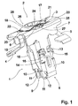
- Fig. 1 shows in a perspective view of an embodiment of a device according to the invention, on the one hand via a one-piece produced by a stamping-bending process of a metal sheet fastener 1 in the form of an airbag mounting bracket and a in the arrangement according to Fig. 1 has inserted into the fastener 1 display element 2, which is preferably made by an injection molding of plastic.
- the fastener 1 has a substantially rectangular cover plate 3, on the short edge sides diametrically opposite each other and from one in the illustration according to Fig. 1 the viewer facing top of the cover plate 3 obliquely away extending support arms 4, 5 are formed.
- the fastening element 1 in each case has a side wall 6, 7, which extend substantially at right angles to the cover plate 3, aligned away from the upper side of the cover plate 3.
- each an elongated mounting arm 8, 9 is formed, the an outer wing 10 and an inner wing 11 has.
- the outer wings 10 and the inner wings 11 are connected to each other via one of the cover plate 3 opposite arranged bending section 12 with each other, wherein the outer wings 10 are radially outward and enclose the oppositely disposed inner wing 11 like a housing.
- each outer wing 10 is formed with two Abstützwangenokomachonne 13, 14, which are arranged approximately centrally in the longitudinal direction of the mounting arms 8, 9 and through which a support cheek 15, 16 passes, the pair of adjacent to the respective outer wing 10 inner wing 11th the relevant fastening arm 8, 9 are mounted.
- the support cheeks 15, 16 are the rear handle with a in Fig. 1 Not shown support member formed and can be due to a formed between the inner wings 11 distance in the radial direction at least so far that they flush with the radially outwardly facing outside of the mounting arms 8, 9 conclude.
- the illustration according to Fig. 1 infer that the likewise elongated display element 2 with a in the in Fig. 1 dome-like from the cover plate 3 away arched dome screen 17 and is formed with a rotary shaft 18 which passes through a introduced in the cover plate 3 of the fastener 1 SchaftausEnglishung 19 and between the mounting arms 8, 9 is arranged. Furthermore, the illustration according to Fig. 1 can be seen that on the dome screen 17 are diametrically opposite two display projections 20, 21 are formed in the pre-assembly according to Fig. 1 in the circumferential direction adjacent to in the cover plate 3 of the fastener 1 introduced reference recesses 22, 23 are.
- the turning shaft 18 has a central, the dome screen 17 by breaking tool receiving recess 24 which is adapted to engage with a in Fig. 1 not shown rotary-push tool is formed, with which, as will be explained in more detail below, the display element 2 relative to the fastening element 1 is rotatable and displaceable in the axial direction.
- a rotational stop cam 27, 28 of a cam arrangement formed on the rotary shaft 18 abuts and thus a rotational movement of the display element 2 with respect to the fastening element 1 when viewed on the top of the cover plate 3 counterclockwise from the respective display projections 20, 21 next adjacent reference recesses 22nd , 23 blocks away.
- Fig. 2 shows in a perspective view of the embodiment according to Fig. 1 with a view of the mounting arms 8, 9 facing bottom of the cover plate 3 of the fastener 1.
- Fig. 2 It can be seen that on the rotation shaft 18 of the display element 2 in addition to the rotation stop cams 27, 28 also two diametrically opposite combination stop cams 29, 30 of the cam assembly are formed in the pre-assembly according to Fig. 2 in sections, a trained on the cover plate 3 height stop tongue 31, 32 of the stop assembly engage behind and thus unintentionally falling out of the display element 2 from the fastener 1 reliably secures over the insertion of the display element 2 in the fastener 1 out going resistance.
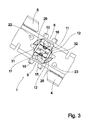
- Fig. 3 shows the fastener 1 in the embodiment according to Fig. 1 and Fig. 2 in a plan view of the top of the cover plate 3.
- Fig. 3 are clearly the diametrically opposed rotational stop tongues 25, 26 and the likewise diametrically opposite reference recesses 22, 23 recognizable.
- Fig. 4 shows in a perspective view, the display element 2 in the embodiment according to Fig. 1 and Fig. 2 , Out Fig. 4
- the rotary shaft 18 has in its connected to the dome shell 17 head portion 33 via two opposing head cheeks 34, 35, to each of which a Drehanschlagsnocke 27, 28 and a ceremoniessanschlagsnocke 29, 30 are formed and formed due to a between them Head breakthrough in the radial direction are so far radially resilient that the combination stop cams 29, 30 are movable between the Drehanschlagszache 25, 26 therethrough.
- each head cheek 34, 35 has a radially projecting depth stop step 36, to which an inserted into the tool receiving recess 24 in the axial direction, in Fig. 4 not shown tool strikes.
- On the side facing away from the dome screen 17 of the head portion 33 of the rotary shaft 18 is formed with a substantially solid foot portion 37 which carries two radially outwardly projecting spring tongues 38, 39 of a spring assembly, which are aligned obliquely to the circumference of the foot portion 37 in the same direction.
- the display element 2 On the side facing away from the head portion 33 of the foot portion 37, the display element 2 is formed with a rectangular cross-section having blade-like Einwirkabêt 40, the flat sides opposite the connecting line between the display projections 20, 21 is aligned, for example, rotated by an acute angle.
- Fig. 5 shows in a longitudinal section the embodiment according to Fig. 1 and Fig. 2 in a pre-assembly, wherein in an assembly process, for example, a relatively thin attachment 41 in the form of an airbag fabric to a rigid support member 42, for example in the form of a body panel of a motor vehicle is to be attached.
- the attachment 41 has an attachment recess 43
- the carrier part 42 has a carrier part recess 44.
- Fig. 6 shows in a cross section through the Einwirkabêt 40 of the display element 2, the pre-assembly according to Fig. 5 , Out Fig. 6 It can be seen that in the still relaxed arrangement of the inner wings 11, the action section 40 is set at an angle so that it is arranged essentially free of influence between the regions of the inner wings 11 which are closest to one another in the radial direction.
- Fig. 7 shows in a cross section through the foot portion 37, the pre-assembly according to Fig. 1 and Fig. 2 in which the free ends of the spring tongues 38, 39 facing away from the foot section 37 rest against the radially inward facing inner sides of the outer wings 10, the spring tongues 38, 39 being slightly biased in the pre-assembly arrangement by slight bending in the direction radially inward and the rotation stop cams 27 , 28 of the the rotatable shaft 18 rotatably mounted on the fastening element 1 are held in abutment with the rotary abutment tongues 25, 26.
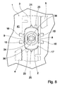
- Fig. 8 shows the pre-assembly of the fastener 1 and the display element 2 according to Fig. 1 and Fig. 2 before the start of the assembly process in a plan view of the top of the cover plate 3.
- the connecting line between the display projections 20, 21 is substantially parallel to the longitudinal side of the cover plate 3 and the display projections 20, 21 in the circumferential direction at a distance from the reference recesses 22, 23 have.
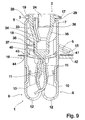
- Fig. 9 shows in a longitudinal section accordingly Fig. 5 the embodiment according to Fig. 1 and Fig. 2 during the assembly process in a pregnantmontagean extract upon sliding of the Abstützwangen 15, 16 at the edge of the Anbauteilausappelung 43 and the Rheinteilausappelung 44 with maximally radially inward spring-loaded inner wings 11.
- the inner wings 11 act on the Einwirkabêt 40 that this is aligned with its flat sides substantially under rotation of the rotary shaft 18 parallel to the outer wings 10 and the inner wings 11.
- Fig. 10 shows in a cross section through the Einwirkabêt 40 accordingly Fig. 5 the intermediate mounting arrangement according to Fig. 9 , Out Fig. 10 It can be seen that the radially inwardly facing flat sides of the inner wings 11 lie flat against the radially outwardly facing flat sides of the action section 40.
- Fig. 11 shows in cross section accordingly Fig. 7 the intermediate mounting arrangement according to Fig. 9 with a relation to the Vormontagean inch maximally twisted rotary shaft 18.
- the illustration according to Fig. 11 can be seen that in this phase of the assembly process, the spring tongues 38, 39 are biased maximum.
- Fig. 12 shows in a plan view accordingly Fig. 8 the opposite of the rotatably anchored in the support member 42 fastener 1 maximally rotated display element 2, which is now aligned so that the display projections 20, 21 of the preassembly position according to Fig. 8 in the presentation according to Fig. 12 clockwise in the circumferential direction on the reference recesses 22, 23 have moved out and now with respect to the pre-assembly according to Fig. 8 on the other side of the next adjacent reference recesses 22, 23 are arranged. If, for example, the assembly process did not continue or only insignificantly continued, the display projections 20, 21 remained essentially in the position shown in FIG Fig. 12 illustrated maximum over-rotated intermediate assembly position and allowed a finding a not correctly completed assembly process.
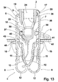
- Fig. 13 shows in a longitudinal section accordingly Fig. 5 and Fig. 9 a final assembly arrangement of the fastening element 1, the display element 2, the attachment 41 and the support member 42 after a proper completion of the assembly process for attaching the attachment 41 to the support member 42, in which the support jaws 15, 16, the support member 42 on the attachment 41 opposite Behind engage behind and the support arms 4, 5 rest on the support member 42 opposite side of the attachment 41.
- the re-relaxed inner wings 11 are again spaced from the exposure section 40.
- it can be Fig. 13 recognize that due to the force exerted by the dome screen 17 bias in the axial direction upon reaching the maximum intermediate assembly position of the display element 2 according to FIG. 9 to FIG.
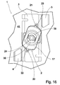
- Fig. 14 shows in a cross section accordingly Fig. 6 and Fig. 10 the again with respect to the inner wings 11 obliquely Asked orientation of the Einwirkabiteses 40, which is now again exposed.
- Fig. 15 shows in a cross section accordingly Fig. 7 and Fig. 11 the further biased spring tongues 38, 39, however, compared to the maximum position during the assembly process in the Eisenmontagean Aunt according to Fig. 11 are noticeably relaxed.
- Fig. 16 shows in a plan view accordingly Fig. 8 and Fig. 12 as a defined mounting display state, a final mounting position of the display element 2 with respect to the fastener 1 in the final mounting arrangement according to FIG Fig. 13 ,
- the display projections 20, 21 are aligned substantially centrally in the axial direction in alignment with the reference recesses 22, 23 and can immediately detect and document the correct intake of the final assembly arrangement, for example by optical sensors.
- a simple turning of the display element 2 from the final assembly position is blocked by the lateral stop of the combination stop cams 29, 30 with the height stop tongues 31, 32.
Landscapes
- Engineering & Computer Science (AREA)
- General Engineering & Computer Science (AREA)
- Mechanical Engineering (AREA)
- Snaps, Bayonet Connections, Set Pins, And Snap Rings (AREA)
Abstract
Description
Die Erfindung betrifft eine Vorrichtung zum Befestigen eines Anbauteiles an einem Trägerteil mit Montagekontrolle gemäß dem Oberbegriff des Patentanspruches 1.The invention relates to a device for attaching an attachment to a support member with assembly control according to the preamble of
Eine derartige Vorrichtung ist aus
Aus
Der Erfindung liegt die Aufgabe zugrunde, eine Vorrichtung zum Befestigen eines Anbauteiles an einem Trägerteil mit Montagekontrolle anzugeben, bei dem der Montageanzeigezustand weitgehend kräftefrei eingenommen wird.The invention has for its object to provide a device for attaching an attachment to a support member with assembly control, in which the mounting indicator state is taken largely free of force.
Diese Aufgabe wird bei einer Vorrichtung zum Befestigen eines Anbauteiles an einem Trägerteil mit Montagekontrolle der eingangs genannten Art erfindungsgemäß mit den kennzeichnenden Merkmalen des Patentanspruches 1 gelöst.This object is achieved according to the invention in a device for attaching an attachment to a support member with mounting control of the type mentioned with the characterizing features of
Dadurch, dass das Anzeigeelement während des Montagevorganges durch Einwirken wenigstens eines Befestigungsarmes auf den länglichen Drehschaft gedreht wird, ist bei einer einfach durchführbaren optischen Kontrolle der für die Montagekontrolle erforderliche Kraftaufwand verschwindend gering.Characterized in that the display element is rotated during the assembly process by the action of at least one mounting arm on the elongated rotating shaft, the effort required for the assembly control is negligible in a simple feasible optical control.
Weitere zweckmäßige Ausgestaltungen sind Gegenstand der Unteransprüche.Further expedient refinements are the subject of the dependent claims.
Weitere zweckmäßige Ausgestaltungen und Vorteile der Erfindung ergeben sich aus der nachfolgenden Beschreibung eines Ausführungsbeispieles der Erfindung mit Bezug auf die Figuren der Zeichnung.Further expedient refinements and advantages of the invention will become apparent from the following description of an embodiment of the invention with reference to the figures of the drawing.
Es zeigen:
- Fig. 1
- in einer perspektivischen Ansicht ein Ausführungsbeispiel einer erfindungsgemäßen Vorrichtung mit einem in ein Befestigungselement eingefügtes Anzeigeelement in einer Vormontagestellung,
- Fig. 2
- in einer perspektivischen Ansicht das Ausführungsbeispiel gemäß
Fig. 1 mit Blick auf eine bei bestimmungsgemäßer Anordnung einem Anbauteil zugewandte Unterseite einer Deckplatte der Vorrichtung, - Fig. 3
- in einer Draufsicht das Befestigungselement bei dem Ausführungsbeispiel gemäß
Fig. 1 undFig. 2 mit Blick auf die bei bestimmungsgemäßer Anordnung einem Anbauteil abgewandten Oberseite der Deckplatte, - Fig. 4
- in einer perspektivischen Ansicht das Anzeigeelement bei dem Ausführungsbeispiel gemäß
Fig. 1 undFig. 2 , das in einem Fußabschnitt mit Federzungen und mit einem Einwirkabschnitt ausgebildet ist, - Fig. 5
- in einem Längsschnitt das Ausführungsbeispiel gemäß
Fig. 1 undFig. 2 in einer Vormontageanordnung vor Beginn eines Montagevorganges, - Fig. 6
- in einem Querschnitt durch den Einwirkabschnitt des Anzeigeelementes das Ausführungsbeispiel gemäß
Fig. 1 undFig. 2 in der Vormontageanordnung gemäßFig. 5 , - Fig. 7
- in einem Querschnitt durch die Federzungen des Anzeigeelementes das Ausführungsbeispiel gemäß
Fig. 1 undFig. 2 in der Vormontageanordnung gemäßFig. 5 , - Fig. 8
- in einer Draufsicht auf die Deckplatte des Anzeigeelementes des Ausführungsbeispieles gemäß
Fig. 1 undFig. 2 in der Vormontageanordnung gemäßFig. 5 mit dem Anzeigeelement in einer Vormontagestellung, - Fig. 9
- in einem Längsschnitt entsprechend
Fig. 5 das Ausführungsbeispiel gemäßFig. 1 undFig. 2 während des Montagevorganges in einer Zwischenmontageanordnung mit maximal eingefederten Befestigungsarmen, - Fig. 10
- in einem Querschnitt durch den Einwirkabschnitt des Anzeigeelementes entsprechend
Fig. 6 das Ausführungsbeispiel gemäßFig. 1 undFig. 2 in der Zwischenmontageanordnung gemäßFig. 9 , - Fig. 11
- in einem Querschnitt durch die Federzungen des Anzeigeelementes entsprechend
Fig. 7 das Ausführungsbeispiel gemäßFig. 1 undFig. 2 in der Zwischenmontageanordnung gemäßFig. 9 , - Fig. 12
- in einer Draufsicht auf die Deckplatte des Anzeigeelementes entsprechend
Fig. 8 das Ausführungsbeispiel gemäßFig. 1 undFig. 2 in der Zwischenmontageanordnung gemäßFig. 9 mit dem Anzeigeelement in einer Zwischenmontagestellung, - Fig. 13
- in einem Längsschnitt entsprechend
Fig. 5 das Ausführungsbeispiel gemäßFig. 1 undFig. 2 nach Beendigung des Montagevorganges in einer Endmontageanordnung, - Fig. 14
- in einem Querschnitt durch den Einwirkabschnitt des Anzeigeelementes entsprechend
Fig. 6 undFig. 10 das Ausführungsbeispiel gemäßFig. 1 undFig. 2 in der Endmontageanordnung gemäßFig. 13 , - Fig. 15
- in einem Querschnitt durch die Federzungen des Anzeigeelementes entsprechend
Fig. 7 undFig. 11 das Ausführungsbeispiel gemäßFig. 1 undFig. 2 in der Endmontageanordnung gemäßFig. 13 und - Fig. 16
- in einer Draufsicht auf die Deckplatte des Anzeigeelementes entsprechend
Fig. 8 undFig. 12 das Ausführungsbeispiel gemäßFig. 1 undFig. 2 in der Endmontageanordnung gemäßFig. 13 mit dem Anzeigeelement in einer Endmontagestellung.
- Fig. 1
- in a perspective view of an embodiment of a device according to the invention with an inserted into a fastener display element in a pre-assembly,
- Fig. 2
- in a perspective view of the embodiment according to
Fig. 1 with a view to a underside of a cover plate of the device, which is intended to be attached to a fixture when it is arranged as intended, - Fig. 3
- in a plan view of the fastener in the embodiment according to
Fig. 1 andFig. 2 with a view to the upper side of the cover plate facing away from an attachment in the intended arrangement - Fig. 4
- in a perspective view of the display element in the embodiment according to
Fig. 1 andFig. 2 formed in a foot section with spring tongues and with an action section, - Fig. 5
- in a longitudinal section of the embodiment according to
Fig. 1 andFig. 2 in a pre-assembly arrangement before the beginning of an assembly process, - Fig. 6
- in a cross section through the Einwirkabschnitt of the display element, the embodiment according to
Fig. 1 andFig. 2 in the pre-assembly according toFig. 5 . - Fig. 7
- in a cross section through the spring tongues of the display element, the embodiment according to
Fig. 1 andFig. 2 in the pre-assembly according toFig. 5 . - Fig. 8
- in a plan view of the cover plate of the display element of the embodiment according to
Fig. 1 andFig. 2 in the pre-assembly according toFig. 5 with the display element in a pre-assembly position, - Fig. 9
- in a longitudinal section accordingly
Fig. 5 the embodiment according toFig. 1 andFig. 2 during the assembly process in an intermediate assembly arrangement with maximum spring-loaded attachment arms, - Fig. 10
- in a cross section through the Einwirkabschnitt of the display element accordingly
Fig. 6 the embodiment according toFig. 1 andFig. 2 in the intermediate mounting arrangement according toFig. 9 . - Fig. 11
- in a cross section through the spring tongues of the display element accordingly
Fig. 7 the embodiment according toFig. 1 andFig. 2 in the intermediate mounting arrangement according toFig. 9 . - Fig. 12
- in a plan view of the cover plate of the display element accordingly
Fig. 8 the embodiment according toFig. 1 andFig. 2 in the intermediate mounting arrangement according toFig. 9 with the display element in an intermediate assembly position, - Fig. 13
- in a longitudinal section accordingly
Fig. 5 the embodiment according toFig. 1 andFig. 2 after completion of the assembly process in a final assembly arrangement, - Fig. 14
- in a cross section through the Einwirkabschnitt of the display element accordingly
Fig. 6 andFig. 10 the embodiment according toFig. 1 andFig. 2 in the final assembly according toFig. 13 . - Fig. 15
- in a cross section through the spring tongues of the display element accordingly
Fig. 7 andFig. 11 the embodiment according toFig. 1 andFig. 2 in the final assembly according toFig. 13 and - Fig. 16
- in a plan view of the cover plate of the display element accordingly
Fig. 8 andFig. 12 the embodiment according toFig. 1 andFig. 2 in the final assembly according toFig. 13 with the display element in a final assembly position.
An jeder Seitenwand 6, 7 ist auf der der Deckplatte 3 abgewandten Seite jeweils ein länglicher Befestigungsarm 8, 9 ausgebildet, der einen Außenflügel 10 und einen Innenflügel 11 aufweist. Die Außenflügel 10 und die Innenflügel 11 sind über jeweils einen der Deckplatte 3 gegenüber liegend angeordneten Umbiegeabschnitt 12 miteinander verbunden, wobei die Außenflügel 10 radial außen liegen und die einander gegenüber liegend angeordneten Innenflügel 11 gehäuseartig umschließen.On each
Weiterhin lässt sich der Darstellung gemäß
Weiterhin lässt sich der Darstellung gemäß
Weiterhin lässt sich der Darstellung gemäß
Zum Überführen der Stellung des Anzeigeelementes 2 in Bezug auf das Befestigungselement 1 von der Anzeige einer korrekten Endmontageanordnung gemäß
Claims (8)
Applications Claiming Priority (1)
| Application Number | Priority Date | Filing Date | Title |
|---|---|---|---|
| DE102012212508.6A DE102012212508A1 (en) | 2012-07-17 | 2012-07-17 | Device for attaching an attachment to a support member with assembly control |
Publications (2)
| Publication Number | Publication Date |
|---|---|
| EP2687731A1 true EP2687731A1 (en) | 2014-01-22 |
| EP2687731B1 EP2687731B1 (en) | 2015-01-07 |
Family
ID=48740905
Family Applications (1)
| Application Number | Title | Priority Date | Filing Date |
|---|---|---|---|
| EP13174336.1A Active EP2687731B1 (en) | 2012-07-17 | 2013-06-28 | Device for securing an attachment section to a carrier with assembly check |
Country Status (2)
| Country | Link |
|---|---|
| EP (1) | EP2687731B1 (en) |
| DE (1) | DE102012212508A1 (en) |
Cited By (5)
| Publication number | Priority date | Publication date | Assignee | Title |
|---|---|---|---|---|
| FR3020098A1 (en) * | 2014-04-22 | 2015-10-23 | Raymond A & Cie | APPARATUS FOR FIXING BY CRAMPONNING |
| WO2018104421A1 (en) * | 2016-12-09 | 2018-06-14 | A.RAYMOND et Cie. SCS | Clip for securing a first element to a second element |
| WO2021071818A1 (en) * | 2019-10-09 | 2021-04-15 | Illinois Tool Works Inc. | Apparatus for fastening a component to a vehicle body part |
| EP3859169A1 (en) * | 2016-04-13 | 2021-08-04 | A. Raymond et Cie. SCS | Clip for fastening a first element to a second element |
| WO2022162557A1 (en) * | 2021-01-29 | 2022-08-04 | A. Raymond Et Cie | Fastener clip |
Families Citing this family (1)
| Publication number | Priority date | Publication date | Assignee | Title |
|---|---|---|---|---|
| DE102015009366A1 (en) | 2015-07-24 | 2017-01-26 | A.RAYMOND et Cie. SCS | Device for holding a component |
Citations (2)
| Publication number | Priority date | Publication date | Assignee | Title |
|---|---|---|---|---|
| EP2204589A1 (en) | 2007-10-24 | 2010-07-07 | Nifco INC. | Clip |
| DE102010008458A1 (en) | 2010-02-18 | 2011-09-08 | A. Raymond Et Cie | fastening device |
Family Cites Families (2)
| Publication number | Priority date | Publication date | Assignee | Title |
|---|---|---|---|---|
| DE202004005819U1 (en) * | 2004-04-08 | 2004-07-08 | Seil- & Netztechnik Reutlinger Gmbh | S-Clip for mounting e.g. motion sensor on suspended ceiling has tabs which fit into T-profile rail, bolt fitting through bore in clip from opposite side to rail |
| DE102009033688B4 (en) * | 2009-07-17 | 2022-05-12 | Zf Automotive Germany Gmbh | Assembly and side gas bag protection device |
-
2012
- 2012-07-17 DE DE102012212508.6A patent/DE102012212508A1/en not_active Withdrawn
-
2013
- 2013-06-28 EP EP13174336.1A patent/EP2687731B1/en active Active
Patent Citations (2)
| Publication number | Priority date | Publication date | Assignee | Title |
|---|---|---|---|---|
| EP2204589A1 (en) | 2007-10-24 | 2010-07-07 | Nifco INC. | Clip |
| DE102010008458A1 (en) | 2010-02-18 | 2011-09-08 | A. Raymond Et Cie | fastening device |
Cited By (15)
| Publication number | Priority date | Publication date | Assignee | Title |
|---|---|---|---|---|
| CN105041796B (en) * | 2014-04-22 | 2018-01-23 | A·雷蒙德公司 | Clamping fastener device |
| RU2661476C2 (en) * | 2014-04-22 | 2018-07-16 | Э Раймон Э Сье | Fixing clamping device |
| WO2015162365A1 (en) | 2014-04-22 | 2015-10-29 | A Raymond Et Cie | Device for attaching using stapling |
| CN105041796A (en) * | 2014-04-22 | 2015-11-11 | A·雷蒙德公司 | Cramping fastener device |
| US9453523B2 (en) | 2014-04-22 | 2016-09-27 | A. Raymond Et Cie | Cramping fastener device |
| JP2017516035A (en) * | 2014-04-22 | 2017-06-15 | ア・レイモン・エ・シエ | Grip fastening device |
| EP2937575A1 (en) | 2014-04-22 | 2015-10-28 | A. Raymond Et Cie | Device for attachment by stapling |
| FR3020098A1 (en) * | 2014-04-22 | 2015-10-23 | Raymond A & Cie | APPARATUS FOR FIXING BY CRAMPONNING |
| EP3859169A1 (en) * | 2016-04-13 | 2021-08-04 | A. Raymond et Cie. SCS | Clip for fastening a first element to a second element |
| CN108223510A (en) * | 2016-12-09 | 2018-06-29 | A·雷蒙德有限合伙公司 | For first element to be fixed on to the fixture in second element |
| WO2018104421A1 (en) * | 2016-12-09 | 2018-06-14 | A.RAYMOND et Cie. SCS | Clip for securing a first element to a second element |
| US11835075B2 (en) * | 2016-12-09 | 2023-12-05 | Raymond Et Cie | Clip for securing a first element to a second element |
| WO2021071818A1 (en) * | 2019-10-09 | 2021-04-15 | Illinois Tool Works Inc. | Apparatus for fastening a component to a vehicle body part |
| WO2022162557A1 (en) * | 2021-01-29 | 2022-08-04 | A. Raymond Et Cie | Fastener clip |
| US11639731B2 (en) | 2021-01-29 | 2023-05-02 | A. Raymond Et Cie | Fastener clip |
Also Published As
| Publication number | Publication date |
|---|---|
| EP2687731B1 (en) | 2015-01-07 |
| DE102012212508A1 (en) | 2014-05-22 |
Similar Documents
| Publication | Publication Date | Title |
|---|---|---|
| EP2687731B1 (en) | Device for securing an attachment section to a carrier with assembly check | |
| DE69817266T2 (en) | Spring clamp for fastening a fuel injector in a connection piece of a fuel distributor | |
| EP2590840A1 (en) | Fixing arrangement for fixing motor vehicle components | |
| WO2009141138A1 (en) | Connection assembly for fastening an attachment element to a support | |
| DE102012001457A1 (en) | fastening system | |
| DE102011109705A1 (en) | steering assembly | |
| WO2009132755A1 (en) | Method and fastening device for fastening a vehicle part to a vehicle | |
| EP1941166B1 (en) | Assembly having a maintaining device for fixing a motor vehicle assembly with a holder and a housing | |
| DE102018110525A1 (en) | Method for mounting a transmission component of a seat height adjustment | |
| DE102018108830A1 (en) | System of an attachment and a holding element | |
| EP3122981A2 (en) | Seal device and fastener | |
| DE102019104398A1 (en) | Isolated mounting system for actuators | |
| DE102013210865B4 (en) | Fully engaged joint arrangement | |
| DE102009013988A1 (en) | Splashboard for motor vehicle, has clutch master cylinder axially fixed at splashboard by rotation by radial extensions, and locking device radially formed outside flange and between cylinder and splashboard in assembly end position | |
| EP3326249B1 (en) | Arrangement comprising a roof system and a fastening system for the fastening of the roof system on the roof of an electrical cabinet | |
| DE102011121860A1 (en) | Internal combustion engine has shaft which is rotatably connected to transmitter element overlapping slot or aperture of shaft for detecting angular position of shaft using sensor positionable in a region of opening of housing | |
| DE2261066B2 (en) | Device for attaching a wheel cover to a wheel having a wheel rim | |
| EP1557643A1 (en) | Angle detector | |
| WO2008058581A2 (en) | Arrangement for sealing a passageway, and mounting method | |
| EP3515790A1 (en) | Sleeve unit for an adjustable steering column of a motor vehicle | |
| DE602004006746T2 (en) | Connecting means for attaching a panel to a body member and panel having such a connecting means | |
| DE102012215873B4 (en) | Method for setting a stop position of a variable-position element on a vehicle body | |
| DE102004049319A1 (en) | Device for fixing a lighting unit and mounting method | |
| EP1526052A1 (en) | Vibration reducing mounting assembly | |
| EP2048377B1 (en) | Device for securing a construction element to a carrier section |
Legal Events
| Date | Code | Title | Description |
|---|---|---|---|
| PUAI | Public reference made under article 153(3) epc to a published international application that has entered the european phase |
Free format text: ORIGINAL CODE: 0009012 |
|
| AK | Designated contracting states |
Kind code of ref document: A1 Designated state(s): AL AT BE BG CH CY CZ DE DK EE ES FI FR GB GR HR HU IE IS IT LI LT LU LV MC MK MT NL NO PL PT RO RS SE SI SK SM TR |
|
| AX | Request for extension of the european patent |
Extension state: BA ME |
|
| 17P | Request for examination filed |
Effective date: 20140130 |
|
| RBV | Designated contracting states (corrected) |
Designated state(s): AL AT BE BG CH CY CZ DE DK EE ES FI FR GB GR HR HU IE IS IT LI LT LU LV MC MK MT NL NO PL PT RO RS SE SI SK SM TR |
|
| GRAP | Despatch of communication of intention to grant a patent |
Free format text: ORIGINAL CODE: EPIDOSNIGR1 |
|
| INTG | Intention to grant announced |
Effective date: 20140818 |
|
| GRAS | Grant fee paid |
Free format text: ORIGINAL CODE: EPIDOSNIGR3 |
|
| GRAA | (expected) grant |
Free format text: ORIGINAL CODE: 0009210 |
|
| RAP1 | Party data changed (applicant data changed or rights of an application transferred) |
Owner name: A. RAYMOND ET CIE |
|
| AK | Designated contracting states |
Kind code of ref document: B1 Designated state(s): AL AT BE BG CH CY CZ DE DK EE ES FI FR GB GR HR HU IE IS IT LI LT LU LV MC MK MT NL NO PL PT RO RS SE SI SK SM TR |
|
| REG | Reference to a national code |
Ref country code: GB Ref legal event code: FG4D Free format text: NOT ENGLISH |
|
| REG | Reference to a national code |
Ref country code: CH Ref legal event code: EP |
|
| REG | Reference to a national code |
Ref country code: IE Ref legal event code: FG4D Free format text: LANGUAGE OF EP DOCUMENT: GERMAN |
|
| REG | Reference to a national code |
Ref country code: AT Ref legal event code: REF Ref document number: 705933 Country of ref document: AT Kind code of ref document: T Effective date: 20150215 |
|
| REG | Reference to a national code |
Ref country code: DE Ref legal event code: R096 Ref document number: 502013000286 Country of ref document: DE Effective date: 20150219 |
|
| REG | Reference to a national code |
Ref country code: NL Ref legal event code: VDEP Effective date: 20150107 |
|
| REG | Reference to a national code |
Ref country code: LT Ref legal event code: MG4D |
|
| PG25 | Lapsed in a contracting state [announced via postgrant information from national office to epo] |
Ref country code: NO Free format text: LAPSE BECAUSE OF FAILURE TO SUBMIT A TRANSLATION OF THE DESCRIPTION OR TO PAY THE FEE WITHIN THE PRESCRIBED TIME-LIMIT Effective date: 20150407 Ref country code: HR Free format text: LAPSE BECAUSE OF FAILURE TO SUBMIT A TRANSLATION OF THE DESCRIPTION OR TO PAY THE FEE WITHIN THE PRESCRIBED TIME-LIMIT Effective date: 20150107 Ref country code: ES Free format text: LAPSE BECAUSE OF FAILURE TO SUBMIT A TRANSLATION OF THE DESCRIPTION OR TO PAY THE FEE WITHIN THE PRESCRIBED TIME-LIMIT Effective date: 20150107 Ref country code: BG Free format text: LAPSE BECAUSE OF FAILURE TO SUBMIT A TRANSLATION OF THE DESCRIPTION OR TO PAY THE FEE WITHIN THE PRESCRIBED TIME-LIMIT Effective date: 20150407 Ref country code: FI Free format text: LAPSE BECAUSE OF FAILURE TO SUBMIT A TRANSLATION OF THE DESCRIPTION OR TO PAY THE FEE WITHIN THE PRESCRIBED TIME-LIMIT Effective date: 20150107 Ref country code: SE Free format text: LAPSE BECAUSE OF FAILURE TO SUBMIT A TRANSLATION OF THE DESCRIPTION OR TO PAY THE FEE WITHIN THE PRESCRIBED TIME-LIMIT Effective date: 20150107 Ref country code: LT Free format text: LAPSE BECAUSE OF FAILURE TO SUBMIT A TRANSLATION OF THE DESCRIPTION OR TO PAY THE FEE WITHIN THE PRESCRIBED TIME-LIMIT Effective date: 20150107 |
|
| PG25 | Lapsed in a contracting state [announced via postgrant information from national office to epo] |
Ref country code: RS Free format text: LAPSE BECAUSE OF FAILURE TO SUBMIT A TRANSLATION OF THE DESCRIPTION OR TO PAY THE FEE WITHIN THE PRESCRIBED TIME-LIMIT Effective date: 20150107 Ref country code: LV Free format text: LAPSE BECAUSE OF FAILURE TO SUBMIT A TRANSLATION OF THE DESCRIPTION OR TO PAY THE FEE WITHIN THE PRESCRIBED TIME-LIMIT Effective date: 20150107 Ref country code: PL Free format text: LAPSE BECAUSE OF FAILURE TO SUBMIT A TRANSLATION OF THE DESCRIPTION OR TO PAY THE FEE WITHIN THE PRESCRIBED TIME-LIMIT Effective date: 20150107 Ref country code: IS Free format text: LAPSE BECAUSE OF FAILURE TO SUBMIT A TRANSLATION OF THE DESCRIPTION OR TO PAY THE FEE WITHIN THE PRESCRIBED TIME-LIMIT Effective date: 20150507 Ref country code: NL Free format text: LAPSE BECAUSE OF FAILURE TO SUBMIT A TRANSLATION OF THE DESCRIPTION OR TO PAY THE FEE WITHIN THE PRESCRIBED TIME-LIMIT Effective date: 20150107 Ref country code: GR Free format text: LAPSE BECAUSE OF FAILURE TO SUBMIT A TRANSLATION OF THE DESCRIPTION OR TO PAY THE FEE WITHIN THE PRESCRIBED TIME-LIMIT Effective date: 20150408 |
|
| REG | Reference to a national code |
Ref country code: DE Ref legal event code: R097 Ref document number: 502013000286 Country of ref document: DE |
|
| PG25 | Lapsed in a contracting state [announced via postgrant information from national office to epo] |
Ref country code: SK Free format text: LAPSE BECAUSE OF FAILURE TO SUBMIT A TRANSLATION OF THE DESCRIPTION OR TO PAY THE FEE WITHIN THE PRESCRIBED TIME-LIMIT Effective date: 20150107 Ref country code: RO Free format text: LAPSE BECAUSE OF FAILURE TO SUBMIT A TRANSLATION OF THE DESCRIPTION OR TO PAY THE FEE WITHIN THE PRESCRIBED TIME-LIMIT Effective date: 20150107 Ref country code: CZ Free format text: LAPSE BECAUSE OF FAILURE TO SUBMIT A TRANSLATION OF THE DESCRIPTION OR TO PAY THE FEE WITHIN THE PRESCRIBED TIME-LIMIT Effective date: 20150107 Ref country code: DK Free format text: LAPSE BECAUSE OF FAILURE TO SUBMIT A TRANSLATION OF THE DESCRIPTION OR TO PAY THE FEE WITHIN THE PRESCRIBED TIME-LIMIT Effective date: 20150107 Ref country code: EE Free format text: LAPSE BECAUSE OF FAILURE TO SUBMIT A TRANSLATION OF THE DESCRIPTION OR TO PAY THE FEE WITHIN THE PRESCRIBED TIME-LIMIT Effective date: 20150107 |
|
| PLBE | No opposition filed within time limit |
Free format text: ORIGINAL CODE: 0009261 |
|
| STAA | Information on the status of an ep patent application or granted ep patent |
Free format text: STATUS: NO OPPOSITION FILED WITHIN TIME LIMIT |
|
| 26N | No opposition filed |
Effective date: 20151008 |
|
| PG25 | Lapsed in a contracting state [announced via postgrant information from national office to epo] |
Ref country code: IT Free format text: LAPSE BECAUSE OF FAILURE TO SUBMIT A TRANSLATION OF THE DESCRIPTION OR TO PAY THE FEE WITHIN THE PRESCRIBED TIME-LIMIT Effective date: 20150107 |
|
| PG25 | Lapsed in a contracting state [announced via postgrant information from national office to epo] |
Ref country code: MC Free format text: LAPSE BECAUSE OF FAILURE TO SUBMIT A TRANSLATION OF THE DESCRIPTION OR TO PAY THE FEE WITHIN THE PRESCRIBED TIME-LIMIT Effective date: 20150107 |
|
| PG25 | Lapsed in a contracting state [announced via postgrant information from national office to epo] |
Ref country code: LU Free format text: LAPSE BECAUSE OF FAILURE TO SUBMIT A TRANSLATION OF THE DESCRIPTION OR TO PAY THE FEE WITHIN THE PRESCRIBED TIME-LIMIT Effective date: 20150628 Ref country code: SI Free format text: LAPSE BECAUSE OF FAILURE TO SUBMIT A TRANSLATION OF THE DESCRIPTION OR TO PAY THE FEE WITHIN THE PRESCRIBED TIME-LIMIT Effective date: 20150107 |
|
| REG | Reference to a national code |
Ref country code: IE Ref legal event code: MM4A |
|
| REG | Reference to a national code |
Ref country code: FR Ref legal event code: ST Effective date: 20160229 |
|
| PG25 | Lapsed in a contracting state [announced via postgrant information from national office to epo] |
Ref country code: IE Free format text: LAPSE BECAUSE OF NON-PAYMENT OF DUE FEES Effective date: 20150628 |
|
| PG25 | Lapsed in a contracting state [announced via postgrant information from national office to epo] |
Ref country code: FR Free format text: LAPSE BECAUSE OF NON-PAYMENT OF DUE FEES Effective date: 20150630 |
|
| PG25 | Lapsed in a contracting state [announced via postgrant information from national office to epo] |
Ref country code: MT Free format text: LAPSE BECAUSE OF FAILURE TO SUBMIT A TRANSLATION OF THE DESCRIPTION OR TO PAY THE FEE WITHIN THE PRESCRIBED TIME-LIMIT Effective date: 20150107 |
|
| REG | Reference to a national code |
Ref country code: CH Ref legal event code: PL |
|
| PG25 | Lapsed in a contracting state [announced via postgrant information from national office to epo] |
Ref country code: CH Free format text: LAPSE BECAUSE OF NON-PAYMENT OF DUE FEES Effective date: 20160630 Ref country code: LI Free format text: LAPSE BECAUSE OF NON-PAYMENT OF DUE FEES Effective date: 20160630 |
|
| PG25 | Lapsed in a contracting state [announced via postgrant information from national office to epo] |
Ref country code: HU Free format text: LAPSE BECAUSE OF FAILURE TO SUBMIT A TRANSLATION OF THE DESCRIPTION OR TO PAY THE FEE WITHIN THE PRESCRIBED TIME-LIMIT; INVALID AB INITIO Effective date: 20130628 |
|
| PG25 | Lapsed in a contracting state [announced via postgrant information from national office to epo] |
Ref country code: CY Free format text: LAPSE BECAUSE OF FAILURE TO SUBMIT A TRANSLATION OF THE DESCRIPTION OR TO PAY THE FEE WITHIN THE PRESCRIBED TIME-LIMIT Effective date: 20150107 |
|
| PG25 | Lapsed in a contracting state [announced via postgrant information from national office to epo] |
Ref country code: BE Free format text: LAPSE BECAUSE OF NON-PAYMENT OF DUE FEES Effective date: 20150630 |
|
| PG25 | Lapsed in a contracting state [announced via postgrant information from national office to epo] |
Ref country code: TR Free format text: LAPSE BECAUSE OF FAILURE TO SUBMIT A TRANSLATION OF THE DESCRIPTION OR TO PAY THE FEE WITHIN THE PRESCRIBED TIME-LIMIT Effective date: 20150107 |
|
| GBPC | Gb: european patent ceased through non-payment of renewal fee |
Effective date: 20170628 |
|
| PG25 | Lapsed in a contracting state [announced via postgrant information from national office to epo] |
Ref country code: GB Free format text: LAPSE BECAUSE OF NON-PAYMENT OF DUE FEES Effective date: 20170628 |
|
| PG25 | Lapsed in a contracting state [announced via postgrant information from national office to epo] |
Ref country code: SM Free format text: LAPSE BECAUSE OF FAILURE TO SUBMIT A TRANSLATION OF THE DESCRIPTION OR TO PAY THE FEE WITHIN THE PRESCRIBED TIME-LIMIT Effective date: 20150107 |
|
| PG25 | Lapsed in a contracting state [announced via postgrant information from national office to epo] |
Ref country code: MK Free format text: LAPSE BECAUSE OF FAILURE TO SUBMIT A TRANSLATION OF THE DESCRIPTION OR TO PAY THE FEE WITHIN THE PRESCRIBED TIME-LIMIT Effective date: 20150107 Ref country code: PT Free format text: LAPSE BECAUSE OF FAILURE TO SUBMIT A TRANSLATION OF THE DESCRIPTION OR TO PAY THE FEE WITHIN THE PRESCRIBED TIME-LIMIT Effective date: 20150107 |
|
| PG25 | Lapsed in a contracting state [announced via postgrant information from national office to epo] |
Ref country code: AL Free format text: LAPSE BECAUSE OF FAILURE TO SUBMIT A TRANSLATION OF THE DESCRIPTION OR TO PAY THE FEE WITHIN THE PRESCRIBED TIME-LIMIT Effective date: 20150107 |
|
| REG | Reference to a national code |
Ref country code: AT Ref legal event code: MM01 Ref document number: 705933 Country of ref document: AT Kind code of ref document: T Effective date: 20180628 |
|
| PG25 | Lapsed in a contracting state [announced via postgrant information from national office to epo] |
Ref country code: AT Free format text: LAPSE BECAUSE OF NON-PAYMENT OF DUE FEES Effective date: 20180628 |
|
| P01 | Opt-out of the competence of the unified patent court (upc) registered |
Effective date: 20230525 |
|
| PGFP | Annual fee paid to national office [announced via postgrant information from national office to epo] |
Ref country code: DE Payment date: 20230620 Year of fee payment: 11 |